1
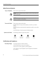
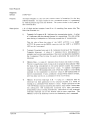
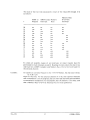
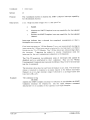
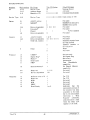
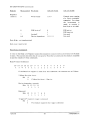
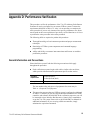
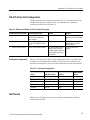
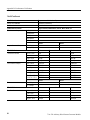
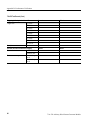
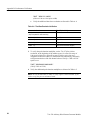
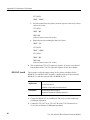
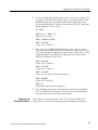
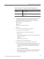
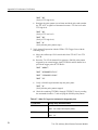
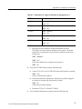
User Manual
73A-270
Arbitrary Pulse/Pattern Generator Module
070-9148-03
This document supports firmware version 1.00
and above.
Warning
The servicing instructions are for use by qualified
personnel only. To avoid personal injury, do not
perform any servicing unless you are qualified to
do so. Refer to the Safety Summary prior to
performing service.
Copyright Tektronix, Inc. All rights reserved.
Tektronix products are covered by U.S. and foreign patents, issued and pending. Information in this publication supercedes
that in all previously published material. Specifications and price change privileges reserved.
Printed in the U.S.A.
Tektronix, Inc., P.O. Box 1000, Wilsonville, OR 97070–1000
TEKTRONIX and TEK are registered trademarks of Tektronix, Inc.
WARRANTY
Tektronix warrants that this product will be free from defects in materials and workmanship for a period of three
(3) years from the date of shipment. If any such product proves defective during this warranty period, Tektronix,
at its option, either will repair the defective product without charge for parts and labor, or will provide a
replacement in exchange for the defective product.
In order to obtain service under this warranty, Customer must notify Tektronix of the defect before the expiration
of the warranty period and make suitable arrangements for the performance of service. Customer shall be
responsible for packaging and shipping the defective product to the service center designated by Tektronix, with
shipping charges prepaid. Tektronix shall pay for the return of the product to Customer if the shipment is to a
location within the country in which the Tektronix service center is located. Customer shall be responsible for
paying all shipping charges, duties, taxes, and any other charges for products returned to any other locations.
This warranty shall not apply to any defect, failure or damage caused by improper use or improper or inadequate
maintenance and care. Tektronix shall not be obligated to furnish service under this warranty a) to repair damage
resulting from attempts by personnel other than Tektronix representatives to install, repair or service the product;
b) to repair damage resulting from improper use or connection to incompatible equipment; or c) to service a
product that has been modified or integrated with other products when the effect of such modification or
integration increases the time or difficulty of servicing the product.
THIS WARRANTY IS GIVEN BY TEKTRONIX WITH RESPECT TO THIS PRODUCT IN LIEU OF
ANY OTHER WARRANTIES, EXPRESSED OR IMPLIED. TEKTRONIX AND ITS VENDORS
DISCLAIM ANY IMPLIED WARRANTIES OF MERCHANTABILITY OR FITNESS FOR A
PARTICULAR PURPOSE. TEKTRONIX’ RESPONSIBILITY TO REPAIR OR REPLACE DEFECTIVE
PRODUCTS IS THE SOLE AND EXCLUSIVE REMEDY PROVIDED TO THE CUSTOMER FOR
BREACH OF THIS WARRANTY. TEKTRONIX AND ITS VENDORS WILL NOT BE LIABLE FOR ANY
INDIRECT, SPECIAL, INCIDENTAL, OR CONSEQUENTIAL DAMAGES IRRESPECTIVE OF
WHETHER TEKTRONIX OR THE VENDOR HAS ADVANCE NOTICE OF THE POSSIBILITY OF
SUCH DAMAGES.
EC Declaration of Conformity
We
Tektronix Holland N.V.
Marktweg 73A
8444 AB Heerenveen
The Netherlands
declare under sole responsibility that the
73A-270
meets the intent of Directive 89/336/EEC for Electromagnetic Compatibility.
Compliance was demonstrated to the following specifications as listed in the Official
Journal of the European Communities:
EN 55011
Class A Radiated and Conducted Emissions
EN 50081-1 Emissions:
EN 60555-2
AC Power Line Harmonic Emissions
EN 50082-1 Immunity:
IEC 801-2
Electrostatic Discharge Immunity
IEC 801-3
RF Electromagnetic Field Immunity
IEC 801-4
Electrical Fast Transient/Burst Immunity
IEC 801-5
Power Line Surge Immunity
To ensure compliance with EMC requirements this module must be installed in a
mainframe which has backplane shields installed which comply with Rule B.7.45 of
the VXIbus Specification. Only high quality shielded cables having a reliable,
continuous outer shield (braid & foil) which has low impedance connections to
shielded connector housings at both ends should be connected to this product.
2863)9(8.32 3286307 2) 2).(&8367 ;.8(-*7 97*7 7 ! 9.08?2 !*78 59.41*28 0377&6= 278&00&8.32 *59.6*1*287 &2) &98.327 278&00&8.32 63(*)96* 278&00&8.32 -*(/0.78 :*6:.*; 63,6&11.2, *59*2(* 63,6&11&'0* *&896*7 6328 &2*0 322*(8367 3;*6?94 =78*1 311&2)7 3)90* 311&2)7 911&6= 311&2) *7(6.48.327 % *0+ !*78 &2) 2.8.&0.>&8.32 63,6&11.2, <&140*7 *+.2.8.32 3+ 311&2)7 63,6&11.2, <&140*7 .2 44*2).< #$'97 4*6&8.32 44*2).< 6328 &2*0 249898498 322*(8.327 44*2).< #$'97 0377&6= 44*2).< *6+361&2(* #*6.+.(&8.32 44*2).< "7*6 *6:.(* General Safety Summary
Review the following safety precautions to avoid injury and prevent damage to
this product or any products connected to it.
Only qualified personnel should perform service procedures.
While using this product, you may need to access other parts of the system. Read
the General Safety Summary in other system manuals for warnings and cautions
related to operating the system.
Injury Precautions
Avoid Electric Overload
To avoid electric shock or fire hazard, do not apply a voltage to a terminal that is
outside the range specified for that terminal.
Do Not Operate Without
Covers
To avoid electric shock or fire hazard, do not operate this product with covers or
panels removed.
Use Proper Fuse
To avoid fire hazard, use only the fuse type and rating specified for this product.
Do Not Operate in
Wet/Damp Conditions
Do Not Operate in an
Explosive Atmosphere
To avoid electric shock, do not operate this product in wet or damp conditions.
To avoid injury or fire hazard, do not operate this product in an explosive
atmosphere.
Product Damage Precautions
Provide Proper Ventilation
Do Not Operate With
Suspected Failures
To prevent product overheating, provide proper ventilation.
If you suspect there is damage to this product, have it inspected by qualified
service personnel.
73A-270 Arbitrary Pulse/Pattern Generator Module
iii
General Safety Summary
Safety Terms and Symbols
Terms in This Manual
These terms may appear in this manual:
WARNING. Warning statements identify conditions or practices that could result
in injury or loss of life.
CAUTION. Caution statements identify conditions or practices that could result in
damage to this product or other property.
Terms on the Product
These terms may appear on the product:
DANGER indicates an injury hazard immediately accessible as you read the
marking.
WARNING indicates an injury hazard not immediately accessible as you read the
marking.
CAUTION indicates a hazard to property including the product.
Symbols on the Product
The following symbols may appear on the product:
DANGER
High Voltage
Protective Ground
(Earth) Terminal
ATTENTION
Refer to Manual
Double
Insulated
Certifications and Compliances
Overvoltage Category
Overvoltage categories are defined as follows:
CAT III: Distribution level mains, fixed installation
CAT II: Local level mains, appliances, portable equipment
CAT I: Signal level, special equipment or parts of equipment, telecommunication, electronics
iv
73A-270 Arbitrary Pulse/Pattern Generator Module
VXIbus Radiated Emissions:
VXIbus Conducted Emissions:
Appendix D: Performance Verification
This procedure verifies the performance of the 73A-270 Arbitrary Pulse-Pattern
Generator. It may be performed in your current VXIbus system if it meets the
requirements described in Table A–2. Also, it is not necessary to complete the
entire procedure if you are only interested in a specific performance area. Some
tests depend on the correct operation of previously verified functions so it is best
to perform the entire procedure in the order presented.
The following skills are required to perform this procedure:
H
Thorough knowledge of test instrument operation and proper measurement
techniques
H
Knowledge of VXIbus system components and command language
programming
H
Ability and facility to construct interconnections and fixtures as needed to
perform the procedure
General Information and Conventions
Please familiarize yourself with the following conventions which apply
throughout the procedure:
H
Each verification sequence begins with a table, similar to the one below,
which provides information and requirements specific to that section.
Equipment
Requirements
Oscilloscope (item 1)
Prerequisites
Prerequisites listed on page 56
Oscilloscope Probe (item 2)
The item number after each piece of equipment refers to an entry in
Table A–1, Required Test Equipment.
H
This procedure assumes that your VXIbus system is configured as indicated
in Table A–3 and that you will be using the National Instruments PC-GPIB
controller, and software (NI-488.2M). In the verification sequences you will
be instructed to issue Interface Bus Interactive Control (ibic) commands to
set up the 73A-270 system. Please refer to the NI-488.2M User Manual for
additional information. If you are using a different controller, simply
substitute the equivalent commands.
73A-270 Arbitrary Pulse/Pattern Generator Module
55
Appendix D: Performance Verification
Prerequisites
The test sequences in this procedure are a valid verification of the 73A-270 when
the following requirements are met:
H
The 73A-270 has been calibrated within the last 12 months
H
The 73A-270 module covers are in place and the module is installed in an
approved VXIbus mainframe according to the procedure in Section 2 of the
Operating Manual
H
The 73A-270 has passed its power-on self test
H
The 73A-270 is operating in an ambient environment as specified in
Section 1 of the Operating Manual and has been operating for a warm-up
period of at least 10 minutes
Equipment Required
This procedure uses traceable signal sources and measurement instruments.
Table A–1 lists the required equipment. You may use equipment other than the
recommended examples if it meets the minimum requirements listed.
Table A–1: Required Test Equipment
Item Number and Description
Minimum Requirements
Example
Purpose
1.
Digitizing Oscilloscope
300 MHz bandwidth; 50 input
impedance; ≤ 1.5% DC vertical
accuracy
Tektronix TDS 460
Checking pulse-pattern signal
timing, amplitude, and phase
2.
Oscilloscope Probe
250 MHz, 10X, 10 M, 12.7 pF
Tektronix P6130
Checking pulse-pattern signal
timing, amplitude, and phase
3.
Counter/Timer
10 MHz frequency measurement
Tektronix 73A-541
Checking pulse/burst accuracy
4.
External Clock Source
25 MHz
Tektronix VX4790A
Checking external clock
5.
50 BNC Coaxial Cable
(two required)
50 impedance; BNC male connectors
Tektronix part number
012-0057-01
Interconnecting electrical
signals
6.
SMB to BNC Adapter Cable
50 impedance; SMB male, BNC
female, connectors
Tektronix VX1729
Interconnecting electrical
signals
7.
BNC Female to BNC Female (barrel)
50 impedance; Female to BNC
Female
Tektronix part number
103-0028-00
Interconnecting electrical
signals
8.
BNC Male to Dual Binding
Post
50 impedance; BNC male, Dual
Binding Post connectors
Tektronix part number
103-0035-00
Interconnecting electrical
signals
9.
DB-25 front panel interconnect assembly
Male DB-25 Connector with 6-inch
jumper wires (26 AWG) soldered to
pins 4 & 5
DB-25, Tektronix part
number 131-0570-00
Interconnecting electrical
signals
56
73A-270 Arbitrary Pulse/Pattern Generator Module
Appendix D: Performance Verification
73A-270-Under-Test Configuration
In order to perform this verification procedure, the 73A-270-under-test must be
installed in an approved VXIbus system. At a minimum, the system must
contain the elements listed in Table A–2.
Table A–2: Elements of a Minimum 73A-270 –Under-Test System
Item Number and Description
Minimum Requirements
Example
Purpose
1.
VXIbus Mainframe
Two available slots for 73A-270
and 73A-541 in addition to the
Slot 0 controller
Tektronix VX1410 VX1400A
Provides power, cooling, and
backplane for VXIbus modules
2.
Slot 0 Controller
Resource Mgr., Slot 0 Device
Functions, IEEE 488 GPIB Interface.
GPIB — VXI
Provides Slot 0 functions,
Resource Mgr., and GPIB/
VXIbus interface
3.
VXIbus System Controller
VXIbus-Talker/Listener/Controller
IBM 486 with National Instruments GPIB PC2A card &
NI-488.2M software and GPIB
cable (Tektronix part number
012-0991-00)
Controlling the VXIbus
System
Test System Configuration
Table A–3 describes the VXIbus system configuration which is assumed in this
procedure. If your configuration is different, you do not need to change it, just
note that you will observe your device names and addresses in the test sequence.
Table A–3: Test System Configuration
Device
GPIB Device Name
VXI Slot
VXIbus Logical
Address
GPIB0
GPIB0
(PC card)
NA
SLOT0
SLOT0
Slot 0
1
73A-270
VX270
Slot 1
2
73A-541
VX541
Slot 2
3
VX4790A
VX4790
Slot 3
4
Test Record
Photocopy the Test Record, and use it to record the performance verification
results for your module.
73A-270 Arbitrary Pulse/Pattern Generator Module
57
Appendix D: Performance Verification
73A-270 Test Record
73A-270 Serial Number:
Temperature and Relative Humidity:
Date of Last Calibration:
Verification Performed by:
Certificate Number:
Date of Verification:
VXIbus Interface Checks
Logical Address, IEEE Address, Slot No., MFG., Model, etc.
Table Command Response
1st Response
2nd Response
3rd Response
4th Response
5th Response
Passed
Program Command Response
Failed
1 MHz Pattern
Interrupt SRQ
TTL OUT A Checks
Time Base Resolution
Pulse Duration Multiplier
Minimum
Measured Value
100 ns ± 10 ns
90 ns
110 ns
1 ms ± 10 ns
99 ns
1.01 ms
10 ms ± 10 ns
9.99 ms
10.01 ms
100 ms ± 10 ns
99.99 ms
100.01 ms
1000 × 100 ns
4,999.5 Hz
5,000.5 Hz
100 × 1 ms
4,999.5 Hz
5,000.5 Hz
10 × 10 ms
4,999.5 Hz
5,000.5 Hz
1 × 100 ms
4,999.5 Hz
5,000.5 Hz
2 × 100 ms
2,499.75 Hz
2,500.25 Hz
85.8585 ms ±20 ns
.
42.4242
ms ±20 nss
85.85848 ms
85.85852 ms
42.42418 ms
42.42422 ms
Passed
Burst Pattern
Maximum
Failed
42 × 1100 ms
21 × 1100 ms
TTL OUT B Checks
Time Base Resolution
58
Minimum
Measured Value
Maximum
100 ns ± 10 ns
90 ns
110 ns
1 ms ± 10 ns
99 ns
1.01 ms
10 ms ± 10 ns
9.99 ms
10.01 ms
100 ms ± 10 ns
99.99 ms
100.01 ms
73A-270 Arbitrary Pulse/Pattern Generator Module
Appendix D: Performance Verification
73A-270 Test Record (Cont.)
TTL OUT B Checks
Pulse Duration Multiplier
Minimum
Maximum
1000 × 100 ns
4,999.5 Hz
5,000.5 Hz
100 × 1 ms
4,999.5 Hz
5,000.5 Hz
10 × 10 ms
4,999.5 Hz
5,000.5 Hz
1 × 100 ms
4,999.5 Hz
5,000.5 Hz
2 × 100 ms
2,499.75 Hz
2,500.25 Hz
85.8585 ms ±20 ns
.
ms ±20 nss
42.4242
85.85848 ms
85.85852 ms
42.42418 ms
42.42422 ms
Passed
Burst Pattern
Measured Value
Failed
42 × 1100 ms
21 × 1100 ms
BPLR OUT A Checks
Voltage
Opposite Phase with TTL OUT
Minimum
Opposite Phase with TTL OUT
± 1.740 V
± 2.260 V
± 5 V ± 260 mV
± 4.740 V
± 5.260 V
± 8.7 V ± 260 mV
± 7.740 V
± 8.260 V
± 8.7 V ± 260 mV
± 7.740 V
± 8.260 V
± 0 V ± 260 mV
± 0.240 V
± 0.240 V
Minimum
Measured Value (voltage & phase)
Maximum
± 2 V ± 260 mV
± 1.740 V
± 2.260 V
± 5 V ± 260 mV
± 4.740 V
± 5.260 V
± 8.7 V ± 260 mV
± 7.740 V
± 8.260 V
± 8.7 V ± 260 mV
± 7.740 V
± 8.260 V
± 0 V ± 260 mV
± 0.240 V
± 0.260 V
Triggering & Breakpoint for Channel A
Trigger Lines
Maximum
± 2 V ± 260 mV
BPLR OUT B Checks
Voltage
Measured Value (voltage & phase)
Passed
Failed
TTLTRG0*
TTLTRG1*
TTLTRG2*
TTLTRG3*
TTLTRG4*
TTLTRG5*
TTLTRG6*
TTLTRG7*
EXT TRG A
Breakpoint
73A-270 Arbitrary Pulse/Pattern Generator Module
59
Appendix D: Performance Verification
73A-270 Test Record (Cont.)
Triggering & Breakpoint for Channel B
Trigger Lines
Passed
Failed
Passed
Failed
TTLTRG0*
TTLTRG1*
TTLTRG2*
TTLTRG3*
TTLTRG4*
TTLTRG5*
TTLTRG6*
TTLTRG7*
EXT TRG A
Breakpoint
External Clock & Transmission In Progress
External Clock
FAST EXT CLK
SLOW EXT CLK
Transmission In Progress
Transmit in Progress A
Transmit in Progress B
60
73A-270 Arbitrary Pulse/Pattern Generator Module
Appendix D: Performance Verification
Self Test
Following the VXIbus system startup sequence, the green PWR light on the
73A-270 front panel indicates that all power supplies are operational. If the +5 V,
–5.2 V, –2 V, ± 24 V or the internally regulated ± 20.9 V buses fail, or if the
–2 V, +5 V, –5.2 V, or ± 24 V fuses open, the PWR light will be off. Additionally, the FAILED light will be on and SYSFAIL* will be asserted indicating a
module failure.
If any of the Mode or Resolution lights are on, it usually is an indication that the
73A-270 has not completed its initialization correctly. One typical reason for this
condition is the FAST EXTERNAL CLOCK switch being in the external (C2)
position.
NOTE. If you experience any error indication from the Slot 0 Resource Manager,
the 73A-270, or other VXIbus module, investigate and correct the problem before
proceeding. Common items to check are logical address conflicts (primary and
secondary; see Table A–3), breaks in the VXIbus daisy chain signals, improper
seating of a module, loose GPIB cable.
Performance Verification Tests
This procedure verifies the performance of the 73A-270. The test sequences
contain setup instructions for the example equipment listed in Table A–1. You
may use equipment other than the recommended examples if it meets the
requirements listed. The order of the test sequences has been chosen to minimize
system setup. Although not essential, it is recommended that you follow the
order presented, as some tests rely on previously verified parameters. Before
starting the the test sequence verify that the SLOW EXTERNAL CLOCK is in
the OFF position and that the FAST EXTERNAL CLOCK is in the C1 position.
Also, ensure that the INT LEVEL is set to the same level as the Slot 0 Commander module.
NOTE. All ASCII character string commands enclosed in quotes which are sent
to the 73A-270 must be in UPPER CASE. You may wish to leave your keyboard
in the CAP LOCK mode.
73A-270 Arbitrary Pulse/Pattern Generator Module
61
Appendix D: Performance Verification
VXIbus Interface
This sequence verifies that the 73A-270 configures correctly and communicates
properly with your system controller.
Equipment
Requirements
Oscilloscope (item 1)
Prerequisites
All prerequisites listed on page 56
50 Coaxial Cable (item 5)
1. Send the appropriate commands to the Slot 0 device to get the primary/secondary GPIB address of the 73A-270, 73A-541, and VX4790A. Place these
addresses into the IBCONF configurator for the VX270. VX541, amd
VX4790A GPIB device.
2. Verify that the 73A-270 responds to setup commands with the following
steps:
a. Connect the 73A-270 TTL OUT A to Ch-1 of the oscilloscope (2 V/div,
250 ns/div, 1 M input impedance).
b. With the following commands, set the 73A-270 to the beginning of the
address space, for the first List entry to have a duration of 500 ns
(5×100 ns power-on default resolution) active high, for the second List
entry to have an active low duration of 500 ns and to be designated as
the Last Address, to transmit the list continuously, and finally to begin
transmission of the last selected channel (in this case Ch A, the power-on
default). Verify a 1 MHz 50% duty cycle pulse-pattern.
(Start GPIB Talker/Listen/Controller program)
(Observe 00 response)
(Observe 1 MHz square wave)
(Observe waveform stops)
3. To verify interrupt capability, set the 73A-270, to enable the transmit
complete interrupt (XMIT), and to generate a burst of (63) pulses. Then read
and verify a response of 02. This response means that there is no transmission in progress, that an interrupt has been generated due to transmission
completion or breakpoint, that the memory is not busy, and that a Memory
Busy Overwrite interrupt has not been generated. Following the read, the
Slot 0 controller will be un-addressed and will acknowledge the interrupt as
an SRQ pending.
62
73A-270 Arbitrary Pulse/Pattern Generator Module
Appendix D: Performance Verification
NOTE. Make sure the 73A-270 and the Slot 0 Resource Manager are set to the
same INT LEVEL. Also, If an embedded controller is being used, follow the
operating manual for displaying the state of the interrupt lines.
(Observe 02 response)
4. Check for VXIbus Request True event by performing a serial poll and verify
that the response byte is
(i.e. DIO7 = 1)
(Observe 40 response)
TTL OUT A and B
This sequence verifies the time base resolution, the pulse duration multiplier, and
the burst mode for the TTL OUT A and B signals. Complete all steps in this
section for TTL OUT A and then repeat all steps for TTL OUT B.
Equipment
Requirements
Oscilloscope (item 1)
Counter/Timer (item 3)
50 BNC Coaxial Cable (item 5)
Prerequisites
All prerequisites listed on page 56
All previous Performance Verification Tests
1. Connect the TTL OUT A (or TTL OUT B) output to Ch-1 of the oscilloscope (2 V/div, 1 ms/div, 1 M input impedance).
2. Verify the time base resolution with the following steps:
a. Select the channel to be tested:
or (Select TTL OUT A or TTL OUT B)
b. Set the 73A-270 for a 100 ns resolution and then to the beginning of the
address space, for the first List entry to have a of 100 ns active high
duration, for the second List entry to have a 100 ns active low duration
and to be designated as the Last Address, to transmit the list continuously, and finally to begin transmission of the last channel selected. Verify a
pulse duration of 100 ns ±10 ns.
73A-270 Arbitrary Pulse/Pattern Generator Module
63
Appendix D: Performance Verification
(Observe 100 ns ±10 ns pulse width)
c. Verify the additional time base resolutions as directed in Table A–4
Table A–4: Time Base Resolution Verification
Command to Send
Pulse Width to Verify
(step 2b repeated for table continuity)
100 ns ±10 ns
1 ms ±10 ns
10 ms ±10 ns
100 ms ±10 ns
(Verify that the waveform stopped)
3. To verify the pulse duration multiplier, set the 73A–270 for a 100 ns
resolution, to the beginning of the address space, for a first List entry of
100 ms active high, for a second List entry of 100 ms active low and
designated as the Last Address, to transmit the list continuously, and finally
to begin transmission of the last channel selected. Verify a 5 kHz ±0.5 Hz
square wave.
(Verify 5 kHz ±0.5 Hz)
4. Verify the additional pulse duration multipliers as directed in Table A–5
NOTE. The last measurement in Table A–5 may require a Timer/Counter if you
wish to verify the precise tolerances listed.
64
73A-270 Arbitrary Pulse/Pattern Generator Module
Appendix D: Performance Verification
Table A–5: Pulse Duration Multiplier Verification
Multiplier /
Resolution
Verify Period and
Duty Cycle
IBWRT "0A0R10001L10004L0C0B"
(step 3 repeated for table continuity)
1000
100 ns
5 kHz ±0.5 Hz, 50%
±0.1%
IBWRT "1R0A1001L1004L0C0B"
100
1 ms
5 kHz ±0.5 Hz, 50%
±0.1%
IBWRT "2R0A101L104L0C0B"
10
10 ms
5 kHz ±0.5 Hz, 50%
±0.1%
IBWRT "3R0A11L14L0C0B"
1
100 ms
5 kHz ±0.5 Hz, 50%
±0.1%
IBWRT "0A21L24L"
2
100 ms
2.5 kHz ±0.25 Hz, 50%
IBWRT "0R0A8585851L4242424L0C0B"
858585 high,
424242 low
Command to Send
85.8585 ms ±20 ns,
42.4242 ms ±20 ns
5. Verify the pulse-pattern burst count function with the following steps:
a. Connect the TTL OUT A or (TTL OUT B) to the counter/timer
INPUT B input.
b. Set the 73A-270 for a 10 ms resolution, to first address location, to
retriggerable mode, for a first List entry of 550 ms active high, and for a
second list entry of 550 ms active low and designated as the Last
Address.
IBWRT "Q"
IBWRT "2R0A0M551L554L"
c. Set the counter/timer for Basic Timer/Counter Measurement Mode, to
Function Event Count B, for a Ch-B Trigger at 1 V, to Gate Indefinitely,
and to return an Integer Format of maximum 217–1 value.
IBFIND VX541
IBWRT "ER"
(Query for any pending ERROR conditions)
IBRD 100
(Observe a 99 response; no ERRORs)
IBWRT "MM0;FN4;BT+100;BZ1;GI;IF17"
IBWRT "JM"
(Start the counter/timer measurement cycle)
d. Set the 73A-270 to generate the pulse-pattern List 42 times and to begin.
73A-270 Arbitrary Pulse/Pattern Generator Module
65
Appendix D: Performance Verification
e. Stop the counter/timer acquisition, read one response, and verify a return
count of 42 events.
(Observe return count of 42 events)
f.
Repeat the burst test sending the data list 21 times.
(Observe return count of 21 events)
6. This completes the TTL OUT signal test sequence. If you have not checked
both channels of the 73A-270, repeat the sequence for the other channel.
BPLR OUT A and B
This sequence verifies the output voltage levels, polarity, and phase for the
BPLR OUT A and BPLR OUT B signals. Complete all steps in this section for
BPLR OUT A and then repeat all steps for BPLR OUT B.
Equipment
Requirements
Oscilloscope (item 1)
Counter/Timer (item 3)
50 BNC Coaxial Cable, two required (item 5)
Prerequisites
All prerequisites listed on page 56
All previous Performance Verification Sequences
1. Connect the BPLR OUT A (or BPLR OUT B) to Ch-1 of the oscilloscope
(50 input impedance)
2. Connect the TTL OUT A (or TTL OUT B) of the 73A-270 under test to
Ch-2 of the oscilloscope (1 M input impedance)
66
73A-270 Arbitrary Pulse/Pattern Generator Module
Appendix D: Performance Verification
3. To verify the BPLR pulse-pattern phase and ±2 V accuracy, set the 73A-270
to generate a continuous pulse-pattern square wave from both the TTL and
the BPLR outputs with a 10 ms period and a bipolar amplitude of ±2.0V.
Check that the BPLR OUT signal is in phase with the TTL OUT signal and
that the amplitude is ±2.0 V ±2 mV.
SET VX270
IBWRT "0S" or IBWRT "1S"
(Select Ch-A or Ch-B)
IBWRT "1R0A0C51L54L0B"
IBWRT "20P-20N"
(Verify ±2.0 V ±260 mV)
4. Reset 73A-270 for a BPLR OUT amplitudes of ±5.0 V and ±8.7 V and
verify that the corresponding BPLR OUT signals are in phase with the TTL
OUT signal and that the amplitude is within ±260 mV of the value set. Then
change the polarity of the BPLR OUT signal and verify. Finally set the
BPLR OUT signal to 0 V and verify.
IBWRT "50P-50N"
(Verify ±5.0 V ±260 mV)
IBWRT "87P-87N"
(Verify ±8.7 V ±260 mV)
IBWRT "-87P87N"
(Verify ±8.7 V ±260 mV and opposite polarity)
IBWRT "00P00N"
(Verify 0.0 V ± 260 mV)
IBWRT "Q"
(Verify that the pulse-pattern is stopped.)
5. The verification steps in this section should be performed for both BPLR
OUT A and BPLR OUT B channels. If you have not tested both channels,
repeat the steps in this section for the other channel.
Triggering, and
Breakpoint Function
This sequence verifies the operation of the 73A-270 with the VXIbus TTL
trigger lines (8), internal and external triggering and breakpoint recognition.
73A-270 Arbitrary Pulse/Pattern Generator Module
67
Appendix D: Performance Verification
Equipment
Requirements
Oscilloscope (item 1)
Counter/Timer (item 3)
50 BNC Coaxial Cable, two required (item 5)
Prerequisites
All prerequisites listed on page 56
All previous Performance Verification Tests
1. Connect TTL OUT A to Ch-2 of the oscilloscope (1 M input impedance).
2. To verify Ch-A operation with the VXIbus TTL trigger lines, Set the
73A-270 for Ch-A to generate a 500 kHz pulse-pattern triggered by an
external trigger from TTLTRG0* and for Ch-B to provide the trigger pulse
on TTLTRG0*. Verify a 500 kHz pulse-pattern and then stop the pattern.
(Observe 500 kHz)
(Verify that the pulse-pattern stopped)
3. Check the remaining TTLTRG1* through TTLTRG7* lines by sending the
commands in table A–6 and verifying a 500 kHz pulse-pattern.
Table A–6: VXIbus TTL Trigger Line Verification Ch. A triggered by Ch. B
TTLTRG Line
Change Setup, Restart Pattern, Verify 500 kHz Pulse-Pattern
TTLTRG1*
(Verify 500 kHz pulse-pattern.)
TTLTRG2*
TTLTRG3*
TTLTRG4*
TTLTRG5*
68
73A-270 Arbitrary Pulse/Pattern Generator Module
Appendix D: Performance Verification
Table A–6: (Cont.)VXIbus TTL Trigger Line Verification Ch. A triggered by Ch. B
TTLTRG Line
Change Setup, Restart Pattern, Verify 500 kHz Pulse-Pattern
TTLTRG6*
TTLTRG7*
4. Using the following commands, disable both channels from the TTLTRGX*
lines and then resend the trigger pulse from channel B to restart the
pulse-pattern from channel A. Check that channel A is not putting out a
pulse pattern, and then stop the pulse-pattern:
(Verify no pulse-pattern from channel A)
5. Verify the EXT TRG A input with the following steps:
a. Connect TTL OUT B to EXT TRG A.
b. Restart both channels with the following command:
c. Verify a 500 kHz pulse pattern from channel A (triggered by channel B)
and then stop the pattern.
(Verify that the pattern stopped)
d. Disconnect TTL OUT B from EXT TRG A.
6. Verify channel A breakpoint recognition with the following steps:
a. Set the 73A-270 to generate a continuous pulse pattern having a 10 ms
active high level pulse with an active breakpoint followed by a 10 ms
active low level pulse with an active breakpoint with the following
commands:
b. Trigger the pulse-pattern and check that the TTL OUT A pulse-pattern is
held at a TTL high level, confirming that the pattern stopped at the
active high pulse breakpoint.
73A-270 Arbitrary Pulse/Pattern Generator Module
69
Appendix D: Performance Verification
(Verify a TTL high level)
c. Retrigger the pulse-pattern several times and check after each start that
the TTL OUT A signal level alternates between a TTL low level and a
TTL high level.
(Verify a TTL low level)
(Verify a TTL high level)
(Verify that the pulse-pattern stops)
7. Verify channel B operation with the VXIbus TTL Trigger Lines with the
following steps:
a. Move the oscilloscope CH-2 coaxial cable from TTL OUT A to TTL
OUT B.
b. Reset the 73A-270 for channel B to generate a 500 kHz pulse-pattern
triggered by an external trigger from TTLTRG0* and for channel A to
provide the trigger pulse on TTLTRG0*.
c. Verify a 500 kHz signal and then stop the pulse-patter:
(Verify that the pulse-pattern stopped)
d. Check the remaining TTLTRG1* through TTLTRG7* lines by sending
the commands in table A–7 and verifying the 500 kHz pulse-pattern.
Table A–7: VXIbus TTL Trigger Line Verification Ch. B triggered by Ch. A
TTLTRG Line
Change Setup, & Restart Pattern
TTLTRG1*
” (Verify a 500 kHz pulse–pattern.)
TTLTRG2*
”
70
73A-270 Arbitrary Pulse/Pattern Generator Module
Appendix D: Performance Verification
Table A–7: (Cont.)VXIbus TTL Trigger Line Verification Ch. B triggered by Ch. A
TTLTRG Line
Change Setup, & Restart Pattern
TTLTRG3*
TTLTRG4*
TTLTRG5*
TTLTRG6*
TTLTRG7*
e. With the following commands, disable both channels from the
TTLTRGX* lines and restart the channel A pulse pattern. Verify that
channel B is not putting out any pulse pattern, and then stop the pulse
transmission:
(Verify that channel B is not putting out any pattern)
8. Verify the EXT TRG B input with the following steps:
a. Connect TTL OUT A to EXT TRG B. Restart both channels by sending:
(Verify a 500 kHz pulse-pattern)
b. Check that channel B is putting out a 500 kHz pulse pattern (triggered
by channel A) and then stop the pattern by sending:
(Verify that the pattern stopped)
c. Disconnect TTL OUT A from EXT TRG B.
9. Verify channel B breakpoint recognition with the following steps:
73A-270 Arbitrary Pulse/Pattern Generator Module
71
Appendix D: Performance Verification
a. Program TTL OUT B to generate a continuous pulse pattern having a 10
ms active high level pulse with an active breakpoint followed by a 10 ms
active low level pulse with an active breakpoint with the following steps:
b. Check that TTL OUT B is held at a TTL high level, which demonstrates
that the pattern stopped at the active high pulse breakpoint.
c. Restart the pulse-pattern several times and check each time that the TTL
OUT B signal level alternates between a TTL low level and a TTL high
level as the breakpoints are being recognized.
(Verify that the pulse-pattern stopped)
72
73A-270 Arbitrary Pulse/Pattern Generator Module
Appendix D: Performance Verification
External Clock and
Transmission In Progress
This sequence verifies the high and low speed external clock inputs and the
Transmission In Progress signal inputs on the front panel DB-25 connector.
Equipment
Requirements
Oscilloscope (item 1)
Oscilloscope Probe (item 2 )
50 BNC Coaxial Cable, two required (item 5)
Arbitrary Waveform or Pattern Generator clock source (item 4)
SMB to BNC Adapter Cable (item 6)
BNC Female to BNC Female (item 7)
BNC Male to Dual Binding Post Adapter (item 8)
DB-25 connector with wires soldered to pins 4 & 5 (item 9)
Prerequisites
All prerequisites listed on page 56
All previous Performance Verification Tests
1. Verify the Fast External Clock (250 kHz to 10 MHz) with the following
steps:
a. Turn the mainframe power off and remove the 73A-270. Change the
FAST EXTERNAL CLOCK switch from the C1 (internal) to the C2
(external) position. Return the 73A-270 to the mainframe and turn on the
mainframe the power.
b. Connect TTL OUT A to Ch-1 of the oscilloscope (2 V/div, 100 µs,
1 M input impedance).
c. Connect the Arbitrary Waveform Generator (AWG) ARB OUT to the
73A-270 Fast External Clock, pin 5 of S1 (front panel DB25, 5th pin up
from bottom right) and pin 4 (4th pin up from bottom right, digital
ground) using the SMB to BNC cable, the BNC barrel connector, the
BNC dual binding post adapter, and two short pieces of 26 AWG jumper
wire soldered to pins 4 and 5 of a male DB-25 connector.
d. Set the clock source (AWG) to generate a 1 MHz square wave.
IBFIND VX4790
IBWRT "SETSQUARE 0 2.5 1000000;1O;T"
(The fourth parameter is numeric one followed by alphabetic O)
73A-270 Arbitrary Pulse/Pattern Generator Module
73
Appendix D: Performance Verification
e. Set the 73A-270 to divide the 1 MHz external clock source by 10 (10 ms
resolution) and to set the pulse duration multiplier to 10 to generate a
square wave with a 200 ms period (5 kHz) with the following steps:
SET VX270
IBWRT "0S1R0A0M101L104L0C0B"
(Verify 5 kHz waveform)
f.
Momentarily disconnect the SMB connector from the VX4790A and
check that the 5 kHz pulse pattern is no longer present on TTL OUT A.
2. Verify the Slow External Clock input with the following steps:
a. Turn the mainframe power off and remove the 73A-270. Return the
FAST EXTERNAL CLOCK switch to the C1 position and change the
SLOW EXTERNAL CLOCK switch to the ON (external) position.
Replace the 73A-270 and turn the mainframe power on. Reconnect the
coaxial cable to the TTL OUT A and the Arbitrary Waveform Generator
(clock source) to pins 5 and 4 (GND) of S1.
b. Program the 73A-270 to select the 200 kHz external clock and to set its
pulse duration multiplier to 20 to generate a 5 kHz square wave:
IBWRT "0S0R0A0M201L204L0C0B"
c. Set the clock source to provide a 200 kHz square wave.
SET VX4790
IBWRT "SETSQUARE 0 2.5 200000;1O;T"
(Verify 5 kHz)
(The fourth parameter is numeric one followed by alphabetic O.)
d. Momentarily disconnect the SMB connector from the VX4790A and
check that the 5 kHz pulse pattern is no longer present on TTL OUT A.
e. Using the oscilloscope probe, verify a 10 MHz clock signal on pin 17 of
S1 (4th pin up from bottom left).
3. Verify the Transmission In Progress signal with the following steps:
a. Turn the mainframe power off and remove the 73A-270. Return the
SLOW EXTERNAL CLOCK switch to OFF and verify that the FAST
EXTERNAL switch is in the C1 position. Reinstall the 73A-270. and
turn on the mainframe power. Reconnect the coaxial cable to TTL OUT
A, and the external clock to S1 pins 5 and 4 (GND).
74
73A-270 Arbitrary Pulse/Pattern Generator Module
Appendix D: Performance Verification
b. Set the 73A-270 to generate a 500 Hz square wave and then stop the
pulse pattern:
(Verify a square wave)
(Verify no pattern)
c. Using the oscilloscope probe, check that S1 pin 2 (Transmission In
Progress A, active high), is a TTL low level and that pin 3 (Transmission
In Progress A, active low) is a TTL high level.
d. Restart the 500 Hz pulse pattern with the command below and check that
pin 2 of S1 is now a TTL high level and pin 3 is a TTL low level.
(Check that pin 2 is high and pin 3 is low)
e. Move the coaxial cable to TTL OUT B. Program the 73A-270 to
generate the 500 Hz pulse-pattern on TTL OUT B and then stop the
pulse pattern:
(Verify a square wave)
f.
Stop the pattern and again using the oscilloscope probe, check that
Transmission In Progress B (active high), pin 12 of S1 (2nd down from
top right,) is a TTL low level and that Transmission In Progress B
(active low), pin 11 (3rd down from top right,) is a TTL high level.
(Verify no pattern and pin 12 is high and pin 11 is low)
g. Restart the 500 Hz pulse pattern and check that pin 12 of S1 is now a
TTL high level and that pin 11 is a TTL low level.
(Verify pin 12 is high and pin 11 is low)
This completes the 73A-270 verification procedure.
73A-270 Arbitrary Pulse/Pattern Generator Module
75
Appendix D: Performance Verification
76
73A-270 Arbitrary Pulse/Pattern Generator Module
# ( $# #"&*"$ "$ $$ &"# $ ' $ #
H
"&$& $
H
#"*" "$#
% #% "" # $ # "&$& $ "&$& *
$ ' "%") ) "&$ %$ "$) # $
$ % # $ # $# "!%" ) ' $# #$ #
%" '" "& $ % " $ %# "
& # %#$ $ %$# $ #$"%$ '$ $*" $
& ) " "$ '$ $*" $ " %" # $"*
$**'$" #%$ $ %# "#& "#
$ "$# " & $"% )%" $"( " " "#$$&
# $ $"( #$"%$# " #$# $ $ "& *
$# # $) & "" ' "" "$# $ # "$$ $ *
% $ ' "$ )%" ""
H
"$ %"
H
#$"%$ $) " %"
H
#$"%$ #" %"
H
#$"%$ $ %" * ) &,$
..
$ # ..
$ ..
,* ")' %( *+
..
,* ")' %( *+
.
.
,* ")' %( *+
..
'$$) ) - +)" × $'++ ..
!" $ )'&+
..
) - !"$$"(* +)" × .
.