1
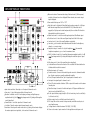
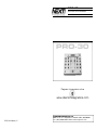
PRO-30
PROFESSIONAL STEREO PREAMP MIXER
OWNER’S MANUAL
PRO-30
Register this product online
@
@
www.stantonmagnetics.com
© 1999, Stanton Magnetics, LLC
STANTON MAGNETICS, LLC
2821 Evans St. Hollywood, FL 33020 (954) 929-8999
Fax: (954) 929-0333 [email protected]
T RO U B LE S H O OT I N G
Thank you for making Next! your first choice in professional DJ mixers.
This new, innovative family of mixers has been developed with input from the professional DJ community, bringing to the marketplace a previously unavailable, affordable combination of user-friendly, functional design, rugged construction, and professional quality features.
Problem
Cause
Solution
Excessive hum when using
phono source.
Poor ground connection.
Properly connect turntable
ground wire to mixer ground
terminal.
Loose cartridge/headshell
connection.
Check cartridge connection
to headshell. Check headshell connection to tonearm.
Low frequency hum while
operating source unit.
Poor AC source ground.
Loose input/output connection. Shorted cable.
Properly ground the AC
source. Check all input and
output connections for
secure fit. Isolate and replace
the damaged cable.
Program volume can’t be
adjusted with master volume
control.
Amplifier or outboard gear
connected to the record output.
Connect amplifier or outboard
gear to master output.
No power.
Improperly connected AC cord
or power line source not on
Properly connect AC cord to
AC power source. Turn power
on.
The amplifier is turned up,
but there is no signal.
Faulty output connections
Properly connect amplifier, or
outboard gear to mixer.
Improper level adjustment.
Properly set crossfader,
channel faders, gain controls, and input selector tog gles.
Next! and your authorized Next! dealer are dedicated to your complete satisfaction
by offering benchmark service and support throughout the long life of your Next!
product.
Again, we appreciate your patronage, and look forward to many years of making
music together.
PLEASE READ CAREFULLY BEFORE USE OF THIS PRODUCT
FAILURE TO FOLLOW THE INSTRUCTIONS PRINTED BELOW MAY VOID WARRANTY
• Follow all security advice printed on your mixer
• When removing the unit's AC plug from the power source, grasp and pull the
plug, NEVER the cord itself!
• Avoid placing your mixer near heat sources, such as power amplifiers.
• When in use, place your mixer on a stable surface, away from vibration. Always
use care when carrying your mixer. Impact, or heavy vibration may compromise
the unit's mechanical integrity. The manufacturer is not responsible for damage
resulting from an impact, or misuse.
• When in use, place your mixer away from sources of hum or noise, such as
transformers, or electric motors.
• To prevent overheating, always provide your mixer with adequate ventilation
air space.
• Avoid stepping on your mixer's AC cord. Repeated compression of the cord
may lead to electrical shorting.
• To avoid damage due to AC voltage peaks, always disconnect your mixer from
the power source during electrical storms.
• Your mixer contains no user-serviceable parts. The manufacturer is not
responsible for any damage or personal injury resulting from unauthorized
user-servicing or modifications. In addition, the warranty will be void if any
unauthorized service by the user is detected. Always return you mixer to an
authorized Stanton dealer for servicing.
No signal in headphones.
Improper connection.
Improper level or cue mix
settings.
Check headphone connection to mixer. Tighten if necessary.
Adjust headphone level and
cue mix to the proper level
and channel settings.
D E S C R I P T IO N O F FU N C TI O N S
1. Input selector switches: Selects phono or line inputs of channels 1 and 2
2. Gain control: Controls the input sensitivity of channels 1 and 2
3. Equalizer: Individual controls for low frequency, midrange, and high frequency
equalization with (+9/-26 dB)
Any changes made to EQ settings will change the
overall output level.
4. Channel faders: Control the output level of channels 1 and 2
5. Crossfader: Fades the master output between channels 1 and 2
6. Level meter: Based upon the meter mode selector (7) setting, the level meter displays
the master output stereo signal level, or the cue levels of channels 1 and 2
7. Meter mode selector: Determines the setting of the level meter (6). When pressed,
cue levels of channels 1 and 2 are displayed. When released, stereo master output
signal is displayed.
8. Power switch: Selects power "ON" or "OFF"
9. Fader Start controls: Activate the Fader Start function when connected to a CD player
with fader start capabilities (such as the Next! NCD-7000). When fader start is
engaged, the CD player can be started and paused by the crossfader. This function is
defeated while crossfader is reversed.
10. Master level control: Controls the overall signal output level of the Master output
11. Booth level control: Controls the overall signal output level of the Booth output
12. Cue level control: Controls the overall headphone output level.
13. Cue select: 3 position selector switch dtermines what is heard in the headphones,
channel 1, 2, or master output
14. Headphone output: Connection for 1/4 inch headphone.
Recommended
headphone impedance is 32-200 ohms for maximum volume
15. Mic EQ: Individual controls for low and high frequencies equalization with (+/-12 dB)
Any changes made to EQ settings will change the overall microphone output
level.
16. Mic volume control: Controls the overall mirophone output level
17. Crossfader Reverse: Reverses the direction of the crossfader. The fader start function
is defeated while crossfader is reversed.
18. Microphone input: 1/4” connector
19. Ground connector: Connects to the turntable ground connector to eliminate electrical
hum. Ground connectors are usually supplied with turntables
20. Phono/CD inputs: Switchable line / phono signal inputs for channels 1 and 2
21. Line inputs: Line signal inputs for channels 1 and 2
22. Phono/CD selector switches: Switches CD/Phono inputs for channels 1 and 2 between
line and phono
23. Fader Start output: Connects to the fader start inputs of CD players with fader start
function such as the Next! NCD-7000
24. Booth output: Auxiliary output, usually for DJ booth monitoring. Level is controlled by
booth level control (11)
25. Master output: Level is controlled by master level control (10)
26. REC output: Record out connects to tape recorder, mini disk recorder, etc. to
record performance
27. Voltage selector: Selects between 115V (US) / 230V (EU)
28. Power cord connector: Input connection for the supplied removable power cord.
C RO S S FA D E R C LE A N I N G
The PRO-30 crossfader may need lubrication from time to time. This will extend
the fader life and eliminate any potential damage due to extended heavy usage.
Cleaning Instructions
1. Remove the crossfader by unscrewing the 2 outer screws (removing the 2
inner screws will detach the fader from the fader plate) and disconnecting the
cable from the mixer.
2. Spray a small amount of cleaner or lubricant into both ends of the fader and
slide the fader back and forth a few times to spread the fluid evenly throughout
the fader.
3. Shake and wipe off excess fluid before re-assembling the fader.
C RO S S FA D E R R E P L AC E M E N T
To replace the cross or channel faders, follow step 1 of the cleaning instructions.
Replacement parts are availabe from Next! or your local Next! dealer.
TE C H N I CA L S P E C I FI C AT I O N S
Line inputs:
Phono inputs:
DJ mic input:
Master output:
Record output:
Headphone output:
Frequency Response:
Tone Control :
Mic Tone:
Gain Control:
S/N Ratio:
T.H.D:
Dimension(LxWxD):
Weight:
2 (RCA), 150 mV / 47K ohm
2 (RCA), 3 mV / 47K ohm
1 (1/4 inch), 1.6 mV / 600 ohm
1 (RCA), 1V / 600 ohm
1 (RCA), 350 mV / 600 ohm
1 (1/4 inch), 32 - 200 ohms recommended
20 Hz - 20 kHz, +/- 0.5 dB
+ 9/-26 dB (Hi, Mid, Low)
Hi/Mid/Lo +/-12 dB
0-20dB
Less than 80dB
0.01% at 1KHz
8.6” x 12.2” x 3.94” (220 x 310 x 100 mm)
8 Lbs (3.5 Kg) power supply included
WA R R A N T Y
This unit has been designed and manufactured using quality
components. Therefore, it is warranted to be free from defects in materials (limited as specified below), and workmanship for a period of thirty
six (36) months from the original purchase date. During this period, all
service and parts necessary to repair a defect will be free of charge. This
limited warranty applies to mechanical parts which are subject to wear
and tear as specified:
• Faders, specified durability: 15,000 cycles
• Rotary potentiometers, specified durability: 10,000 cycles
• Switches, specified durability: 10,000 cycles
Consequently, the parts listed above are warranted to be free from
defects in materials and workmanship for a period of thirty days (30)
days from the original purchase date.
FOR THE WARRANTY TO BE VALID, PLEASE COMPLETE THE
ONLINE WARRANTY REGISTRATION FORM FOUND AT
WWW.STA N TO N M AG N E TI CS . CO M
2821 Evans Street • Hollywood, FL 33020