1
OWNER'S
MANUAL
MODEL NO.
917.255590
Caution:
Read and follow
all Safety Rules
and instructions
Before Operating
This Equipment
, Assembly
• Operation
. Customer Responsibilities
• Service and Adjustment
° Repair Parts
Sears,
Roebuck
and Coo, Chicago,
JL 60684 U.S°A.
SAFETY
Practices RULES
for Ride°On
Safe Operation
....
.........
Mowers
&
IMPORTANT: THIS CUTTING MACHINE IS CAPABLE OF AMPUTATING HANDS AND FEET AND THROWING OBJECTS,
FAILURE TO OBSERVE THE FOLLOWING SAFETY INSTRUCTIONS COULD RESULT IN SERIOUS INJURY OR DEATH,
i
i
L
e
o
GENERAL
OPERATmON
Read, understand, and follow alt instructions in the manual
and on the machine before starting,
Only allow responsible adults, who are familiar with the
instructions, to operate the machine.
Clear the area of objects such as rocks, toys, wire, etc., which
could be picked up and thrown by the blade,
Be sure the area is clear of other people before mowing. Stop
machine if anyone enters the area,
Never carry passengers.
Do not mow in reverse untess absolutely necessary.
look down and behind before and while backing.
e
I& CHILDREN
Tragic accidents can occur if the operator is not alert to th_
presence of children, Children are often attracted to the machin_
and the mowing activi_. Never assume that children will remair_
where you last saw them.
o
o
Before and when backing, _ook behind and down for smali
children.
Always
Never carry children, They may fall off and be seriously
injured or interfere with the safe machine operation.
Never allow cNdren to operate the machine.
Use extra care when approaching blind corners, shrubs,
trees, or other objects that may obscure vision.
Be aware of the mower discharge direction and do not point
it at anyone. Do not operate the mower without either the
entire grass catcher or the guard in place.
Slow down before turning.
Never leave a running machine unattended. Always turn off
blades, set parking brake, stop engine, and remove keys
before dismounting,
IV. SERVICE
o
Turn off btades when not mowing.
Stop engine before removing grass catcher or unclogging
chute.
Mow only in daylight or good artificial light.
Do not operate the machine while under the influence of
alcohol or drugs.
Watch for traffic when operating near or crossing roadways,
Use extra care when loading or unloading the machine into a
trailer or truck.
.
,
Slopes are a major factor related to loss-of-control and tipover
accidents, which can result in severe injury or death. All slopes
require extra caution. If you cannot back up the slope or if you feel
uneasy on it, do not mow it.
-
DO:
"
Mow up and down slopes, not across.
Remove obstacles such as rocks, tree limbs, etc.
o
Watch for holes, ruts, or bumps.
Uneven terrain could
overturn the machine. Tall grass can hide obstacles.
Use slow speed. Choose a low gear so that you will not have
to stop or shift while on the slope.
Follow the manufacturer's recommendations for wheet weights
or counterweights to improve stability.
Use extra care with grass catchers or other attachments.
These can change the stability of the machine.
•
.
•
•
.
o
o
o
Keep nit movement on the slopes sfowand gradual Do not
make sudden changes in speed or direction.
Avoid starting or stopping on a slope. If tires lose traction,
disengage th'e blades and proceed slowly straight down the
slope.
•
=
o
,
Do not turn on slopes unless necessary, and then, turn slowly
and gradually downhill, if possible.
Do not mow near drop-offs, ditches, or embankments.
The
mower could suddenly turn over if a wheel is over the edge of
a cliff or ditch, or if an edge caves in,
Do not mow on wet grass. Reduced traction could cause
sliding.
Do not try to stabilize the machine by putting your foot on the
ground.
Do not use grass catcher on steep slopes.
Keep nuts and bolts, especiafiy blade attachment bolts, tight
and keep equipment in good condition.
Never tamper with safety devices.
Check their proper
operation regularly.
Keep machine free of grass, leaves, or other debris build-up.
Clean oil or fuel spillage. AtSow machine to cool before
storing.
Stop and inspect the equipment if you strike an object.
Repair, if necessary, before restarting.
Never make adjustments or repairs with the engine running.
Grass catcher components are subject to wear, damage,
and deterioration, which coutd expose moving parts or allow
objects to be thrown. Frequently check components and
replace with manufacturer's recommended parts, when neck.
essary.
Mower blades are sharp and can cut. Wrap the blade(s) or
wear gloves, and use extra caution when servicing them.
Check brake operation frequently. Adjust and service as
required.
Look for this syr_bo_ to point out important safety
precautions,
_t means
CAW]ON.q. v BECOI_EALERT!!!
YOUR
SAFETY iS iNVOLVED°
DO NOT:
o
Use extra care in handling gasoline and other fuels. They
are flammable and vapors are explosive.
Use only an approved container.
*
Never remove gas cap or add fuel with the engine
running. Allow engine to coo_ before refueling. Do no_.
smoke.
Never refuel the machine indoors.
Never store the machine or fuel container inside where
there is an open flame, such as a water heater.
Never run a machine inside a closed area.
I1. SLOPE OPERATION
o
Keep children out of the mowing area and under the watchfu!
care of another responsible adult.
Be alert and turn machine off if children enter the area.
CAUTaON:
Amways disconnect
spark
contact spark p_ug in order to prewnt
plug wire andstarting
#face wire
where
it cannot
accidental
when
setting
up,
transporting,
adjusting
or making
repairs,
2
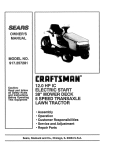
CONGRATULATIONS
on your purchaseof a Sears
Tractor. tt has been designed,engineered and manu-
PRODUCT
HORSEPOWER:
12.5
GASOLINE CAPACITY:
5 QUARTS
UNLEADED REGULAR
OiL (3.0 PINTS):
SAE 30 (or 10W-30)
WINTER: SAE 5W-30
SPARK PLUG (GAP.030 IN.);
CHAMPION RJ-19LM
STD361458
VALVE CLEARANCE:
iNTAKE .005 - .007 IN.
EXHAUST .009 - .011 IN.
GROUND SPEED:
FORWARD: 0-5.5 MPH
REVERSE: 0-2,2 MPH
SERIAL
NUMBER
TIRE PRESSURE:
FRONT: 14 PSi
REAR: 10 PSI
DATE OF PURCHASE
CHARGING SYSTEM:
3 AMPS BATTERY
5 AMPS HEADLIGHTS
THE MODELAND SERIAL NUMBERS WILL BE FOUND
ON A PLATE UNDER THE SEAT.
BLADE BOLT TORQUE:
30-35 FT, LBS,
factured to give you the best possible dependability
performance.
and
Should you experience any problem you cannot easily
remedy, please contact your nearest Sears Service
Center/Department.
We have competent, well-trained
technicians and the proper tools to service or repair this
unit.
Please read and retain this manual. The instructions will
enable you to assemble and maintain your unit properly.
Always observe the "SAFETY RULES".
MODEL
NUMBER
917.255590
YOU SHOULD RECORD BOTH SERIAL NUMBER AND
DATE OF PURCHASE AND KEEP IN A SAFE PLACE
FOR FUTURE REFERENCE.
WARNING: This unit is equipped with an internal combustion engine and should not be used on or near any unimproved forest-covered, brush-covered or grass-covered
land unless the engine's exhaust system is equipped with
a spark arrester meeting applicable local or state laws (if
any). tf a spark arrester Jsused, it should be maintained in
effective working order by the operator.
In the state of California the above is required by law
(_Section 4442 of the California Public Resources Code).
Other states may have similar laws. Federal taws apply on
federal lands. A spark arrester for the muffler is available
through your nearest Sears Authorized Service Center
(See REPAIR PARTS section of this manual).
MAWNTENANCE AGREEMENT
A Sears Maintenance Agreement is available on this product. Contact your nearest Sears store for details.
CUSTOMER
•
RESPONSIBALtTIES
Read and observe the safety rules.
Follow a regular schedule in maintaining, caring for and
using your unit.
•
SPEC FmCATIONS
Follow the instructions under "Customer Responsibilities" and "Storage" sections of this owner's manual.
LIMITED TWO YEAR WARRANTY
ON ELECTRIC
START RIDING EQUIPMENT
For two (2) years from the date of purchase, if this riding equipment is maintained, lubricated and tuned up according to the
instructions in the owner's manual, Sears will repair or replace, free of charge, any parts found to be defective in material or
workmanship,
This Warranty does not cover:
•
•
o
Expendable items which become worn during normal use, such as blades, spark plugs, air cleaners and belts.
Tire replacement or repair caused by punctures from outside objects, such as naits, thorns, stumps, or glass.
Repairs necessary because of operator abuse, negligence, improper storage or accident or the failure to maintain the
equipment according to the instructions contained in the owner's manual,
Riding equipment used for commercial or rental purposes.
LiMiTED 90 DAY WARRANTY
ON BATTERY
For 90 days from date of purchase, if any battery included with this riding equipment proves defective in material or workmanship
and our testing determines the battery wil_not hold a charge, Sears will replace the battery at no charge,
WARRANTY SERVICE IS AVAILABLE BY RETURNING THE RIDING EQUIPMENT TO THE NEAREST SEARS SERVICE
CENTER/DEPARTMENT tN THE UNITED STATES.
This Warranty gives you specific legal rights, and you may also have other rightswhich may vary from state to state.
SEARS, ROEBUCK AND CO., Di731CR-W, SEARS TOWER, CHICAGO, ILLINOIS 60684
3
TABLE OF CONTENTS
SAFETY RULES ............................................................
2
PRODUCT SPECIFmCATIONS ....................................... 3
CUSTOMER RESPONSIBILITIES
..................... 3, 14-17
WARRANTY ...................................................................
3
TABLE OF CONTENTS .................................................
4
iNDEX .............................................................................
4
TRACTOR ACCESSORIES ........................................... 5
ASSEMBLY ................................................................
7-9
OPERATION ...........................................................
10-13
MAINTENANCE SCHEDULE ...................................... 14
SERVICE AND ADJUSTMENTS ............................ 18.2t_
STORAGE ....................................................................
25
TROUBLESHOOTING
............................................
26-27
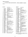
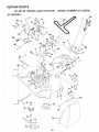
REPAIR PARTS - TRACTOR ................................. 29-50
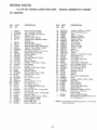
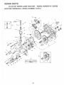
REPAIR PARTS - ENGINE ..................................... 46-5G
REPAIR PARTS - TRANSAXLE ............................ 44-45
PARTS ORDERING/SERViCE ................... BACK PAGE
raND
A
E
Accessories ............................................. 5
Adjustments:
Brake ........... :............................... 20
Carburetor ...................................
24
Mower
Front-To-Back ........................ t9
Side-To-Side .......................... t 9
Throttle Control Cable ................. 24
Air FiIter, Engine ................................. 17
Air Screen, Engine ............................. 17
Assembly ...........................................
7-9
B
Battery:
Charging ........................................
8
Cleaning ......................................
17
install ation .....................................
9
Levels .......................................
8,t 5
Preparation .................................... 8
Starting with Weak Battery .......... 22
Storage ........................................
25
Terminals ....................................
t5
Belt:
Motion Drive
Removal/Replacement
........... 20
Mower Blade Drive
Removal/Replacement
........... 20
Blade:
Sharpening ..................................
Replacement ...............................
Brake Adjustment ...............................
15
15
20
C
Carburetor Adjustment ....................... 24
Controls, Tractor ................................. 10
Customer Responsibilities ............. 14-t7
Engine:
Air Filter ...................................
17
Air Filter Foam Pre-Cleaner .... t7
Air Screen, Engine .................. 17
Battery .....................................
15
Cooling Fins, Engine ............... 17
Engine Oil ................................ 16
Fuel Filter ................................ t 7
Spark Plugs ............................. 17
Tractor:
Blade .......................................
15
Lubrication Chart ..................... t 4
Maintenance Schedule ............ 14
Tire Care ......................... 8,15,22
Cutting Height, Mower ........................ t t
D
Electrical:
interlocks and Relays .................. 23
Schematic ................................... 28
Wiring Diagram ............................ 30
Engine:
Air Filter .......................................
17
Air Filter Foam Pre-Cleaner ........ 17
Air Screen ................................... 17
Cooling Fins, Engine ................... 17
Oil Change .................................. 16
Oil Level ................................. 12,16
Oil Type .......................................
i6
Preparation .................................. 12
Repair Parts ........................... 46-50
Starting ........................................
13
Storage ........................................
25
F
Filter:
Air Filter .......................................
17
Air Filter Foam Pre-Cleaner ........ 17
Fuel .............................................
17
Fuel:
Type ............................................
t2
Storage ........................................
25
Fuse ....................................................
23
H
Hood Removal/Installation
.................. 23
L
Leveling Mower Deck .........................
Lubrication:
Chart ............................................
19
Maintenance
Mower:
14
Schedule .......................
Adjustment, Front-to-Back ...........
Adjustment, Side-to-Side .............
Blade Sharpening ........................
Blade Replacement .....................
Cutting Height ..............................
Installation ...................................
Operation .....................................
Removal ......................... :............
Mowing Tips .......................................
Muffter .................................................
Spark Arrester ..........................
14
t9
19
15
15
11
18
12
18
t3
17
3,38
O
Oil:
Cold Weather Conditions ....... ! 2,16
Engine .........................................
16
Decals, Wheels & Tires ...................... 29
4
Storage ........................................
25
Transaxle .................................... 16
Operation ......................................
10-13
Operating Mower ................................ 12
Options:
Accessories ................................... 5
Spark Arrester .......................... 3,38
P
Parking Brake ................................ 10-1 !
Parts Bag ..............................................
6
Parts, Replacement/Repair
........... 29-45
Product Specifications ........................... 3
R
Repair Parts ..................................
29-45
S
Safety Rules .......................................... 2
Seat ......................................................
8
Service and Adjustments .............. 18-24
Carburetor ................................... 24
Fuse ............................................
23
Hood Removal/Installation .......... 23
Motion Drive Belt
Removal/Replacement
........... 20
Mower Blade Drive Belt
Removal/Replacement
........... 20
Mower Adjustment
Front- to-Back ........................ 19
Side-to-Side ............................ 19
Mower Removal .......................... 18
Tire Care ............................. 8,15,22
Slope Guide Sheet ............................. 5t
Spark Arrester .................................... 38
Spark Plugs ........................................
t7
Specifications ....................................... 3
Starting the Engine ........................ 12-13
Steering Wheel ................................ 7,22
Stopping the Tractor ........................... 11
Storage ...............................................
25
T
Throttle Control Cable
Adjustment .................................. 24
Tires ................................................... 8,t5,22
Trouble Shooting Chart .................. 26-27
Transaxle:
Repair Parts ........................... 42-43
Pump ...........................................
!6
W
Warranty ...............................................
Wiring Diagram ...................................
Wiring Schematic ...............................
3
30
28
ACCESSORIES
AN
ATTACHMENTS
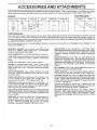
These accessories and attachments were available when the unit was purchased. They are a_so available at most Sears retail outfets,
catalog and service centers.
Most Sears stores can order these items for you when you provide the model number of your tractor.
ENGINE
SPARK PLUG
NA_NTENANCE
MUFFLER
AIR FILTER
GAS CAN
ENGINE OIL
STABILIZER
8kADES
BELTS
PERFORMANCE
Sears offers a wide variety of attachments that fit your vehicle. Many of these are listed below with brief explanations of how they can help
you. This list was current at the time of publication; however, it may change in future years - more attachments may be added, changes may
be made in these attachments, orsome may no longer be available orfit your model. ContactyournearestSearsstorefortheaccessotie$
and attachments
that are available for your unit,
Most of these attachments
attaching and detaching.
do not require additional hitches or conversion
SNOW BLADE for snow removal only. 14-inch high, 42-inch
wide blade clears 38-inch path when angled left or right, Raises,
iowers with side lever. Adjustabie skids; replaceable, reversible
scraper bar. (Use with tire chains, wheel weights, or rear drawbar
weight.)
PERMANEX
BAGGER tats you collect grass clippings and
leaves for a healthier, nearer looking lawn. Two Permanex
containers hold 30-gailon plastic bags.
LAWN SWEEPERS let you collect grass clippings and leaves.
LAWN VACS for powerful collection of heavy grass clippings and
leaves. Wand attachment to pick up debris in hard-to-reach
places.
SNOWTHROWER has 40-inch swath, Drum4ype auger handles
powdery and wet/heavy snow. Mounts easily with simple pin
arrangement. Discharge chute adjusts from tractor seat. (;-inch
diameter spout discharges snow 10 to 50 feet. Lift controlled at
tractor seat. (Use with chains, wheel weights, or rear drawbar
weight.)
CARTS make hauling easy. Variety of sizes available.
ROLLER for smoother lawn surface.
36-inch wide, 18-inch
diameter water-tight drum holds upto390 Ibs. ofweight. Rounded
edges prevent harm to turf. Adjustable scraper automatically
cleans drum.
SPREADER!SEEDERS
kiIling easy. Broadcast
de-icers and sand.
kits (those that do are indicated) and are designed for easy
TIRE CHAINS are heavy duty; closely spaced extra-large cross
links give smooth ride, outstanding traction.
make seeding, fertilizing, and weed
spreaders are also useful for granular
WHEEL WEIGHTS for rear wheels provide needed traction for
snow removal or dozing heavy materials. In pairs. (30 Ibs. each.)
CORING AERATOR takes small plugs out of soil to allow moisture and nutrients to reach grass roots. 36-inch swath, 24
hardened steel coring tips. 150 lb, capacity weight tray.
TRACTOR CAB has heavy duty vinyl fabric over tubular steel
frame, ABS plastic top; clear plastic windshield offers 360 degree
visibility. Hinged metal doors with catch. Keeps operator warm
and dry. Remove vinyl and windshields for use as sun protector
in summer. (Catalog only.)
AERATOR promotes deep root growth for a healthy lawn. Tapered 2,5-inch steel spikes mounted on 10-inch diameter discs
puncture holes in soil at close intervals to let moisture soak in.
Steel weight tray for increased penetration.
Optional accessories for tractor cab: tinted/tempered solid
safety glass windshield with hand operated wiper; 12-volt amber
caution light for mounting on cab top, (Catalog only.)
MULCH RAKE/DETHATCHER
!oosens soi! and flips thatch and
matted leaves to lawn surface for easy pickup. Twenty spring tine
teeth. Useful to prepare bare areas for seeding. Available for front
or rear mounting,
TRACTOR COVER protects tractor from weather.
Made of
Evolution 3 fabric (water-repellent, extremely breathable, light
weight, soft, non-abrasive, pliable in all temperatures, durable,
stain/tear/puncture resistant, will not shrink or stretch.) (Catalog
only.)
SPRAYERS use 12-volt DC electric motor that connects to the
tractor battery or other 12-vott source.
Includes booms for
automatic spraying when putling, and hand held wand for spot
spraying.
Wand has adjustable spray pattern. For applying
herbicides, insecticides, fungicides, and fiquid fertilizers,
5
CONTENTS
Parts Bag contents
OF HARDWA
shown full size
PACK
Parts packed
separately
in carton
\
Seat
i
f
O
Metal
(2)
Screws
Sheet
#!0-t6 x 1/2
l'
Steering
Wheel
(1) Locknut 3/8-24
(1) 2_3/8" Dia. Washer
Battery acid
Battery
'"i
Steering
Boot
(t) Hex Bolt 1/2-13 x t
Owner's Manual
Parts Bag
(I) Shoulder Bolt 5/t6-t8
'
0
\\
Parts bag contents
not shown
full size
tM,,
__
/
(1) Lock Washer 1/2
Steering
Whee!
Steering Wheel
Adapter
!nsert
(1) Washer 17/32 x 1-3/16 x 12 Ga.
_(2)
@
(2) Hex Bolts 1/4 - 20 x 3/4
Keys
Steering
Bushing
¢
(2) Hex Nuts 1/4- 20
z
z
p .................
(2) Lock Washers
I/4
15 ° Slope Sheet
(2) Washers 9/32 x 5/8 x 16 Ga.
6
Battery Caps
and mnstructlons
BLY
ASSE
TOOLS
............
!
REQUIRED
FOR ASSEMBLY
A socket wrench set will make assembly easier. Standard
wrench sizes are listed.
(i)
(1) 9/!6" wrench
5/16" wrench
(2) 7/16" wrenches
Tire pressure gauge
Screwdriver
(1) 1/2" wrench
Utility knife
When right and left hand is mentioned in this manual, it
means when you are in the operating position (seated
behind the steering wheel).
TO REMOVE
UNPACK
STEERING
BUSHING
CARTON
-
Remove all accessible loose parts and parts cartons
from carton (See page 6).
•
Cut along dotted lines on carton, from top to bottom, all
four corners of carton and lay panels flat.
•
Check for any additional
remove.
BEFORE
ATTACH
STEERING
BOOT
UNIT FROM CARTON
ROLMNG
loose parts or cartons and
UNIT OFF SKtD
STEE!RJNG WHEEL
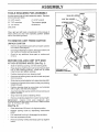
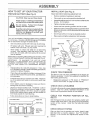
(See Fig, 1)
o
Slide the steering bushing over the steering shaft.
,
Raise steering shaft forward until screw holes in dash
line up with steering bushing. Install two (2) sheet
metal screws and tighten securely.
o
Position steering boot over steering shaft.
,
Place tabs of steering boot over slots in dash and push
down to secure.
-
Slide steering wheel adapter onto upper steering shaft.
,
Position front wheels of the tractor so they are pointing
straight forward.
,
Position steering wheel so cross bars are horizontal
(left to right) and slide onto adapter.
•
Assemble large flat washer and 3/8-24 hex fockn ut and
tighten securely.
°
Snap insert into center of steering wheel.
STEERING
(SHiPPiNG
POSiTiON)
STEERING SHAFT
(ASSEMBLY POSITION)
FIG. 1
o Remove protective plastic from tractor hood and grill.
IMPORTANT;
CHECK
FOR AND REMOVE
ANY
STAPLES IN SKID THAT MAY PUNCTURE TIRES WHERE
UNIT IS TO ROLL OFF SKID.
(See Fig. 6)
,
Raise attachment
lift lever to its highest position.
,
Release parking
pedal.
brake by depressing
o
Pull freewheel knob up to disengage transmission.
o
Roll unit backwards off skid.
o
Remove banding holding discharge guard up against
tractor.
clutch/brake
7
SHAFT
ASSE
BLY
HOW TO SET UP YOUR TRACTOR
_NSTALL
PREPARE
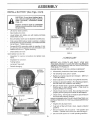
Adjust seat before tightening adjustment bolt.
BAKERY
(See Fig,21
SEAT (See Fig, 3}
o
°
Remove cardboard packing on seat pan,
P_ace seat on pan and assemble shoulder bolt.
Wash hands or c_othing _rnmedlately if
accidentally in contact with battery acid.
•
Assemble adjustment bolt, tock washer and flat washer
loosely. Do not tighten,
Do not smoke. Fumes from
battery acid are e×p_osiveo
•
Tighten shoulder bolt securely.
CAUTION:
Wear eye a_d face shield.
charged
o
Lower seat into operating position and sit on seat.
Slide seat until a comfortable position is reached which
allows you to press clutch/brake pedal all the way down
(See Fig. 6).
Read the instructions included with the
battery vent ¢apso Always wear gloves,
c_othing and goggles to protect your
hands_ skin and eyes.
•
Get off seat without moving its adjusted poskion.
•
Raise seat and tighten adjustment bolt securely.
Your unit has a battery charging system which is sufficient
for normal use. However, periodic charging of the battery
with an automotive charger writ extend its life.
o
See instructions packed with vent caps in parts bag.
o
Fil! battery with acid. Fill each celt until it reaches the
bottom of the vent wetIs. Do not overfill.
Allow battery to stand and settle for at least thirty
minutes. After standing, check the level of acid. if
beiow the vent wells, add more acid until the correct
level is reached.
Wah)/e,_ttt __iri)_jSet
_n d_negd
! tftoe_ a111 _ _cal)ae_y
{_ whi_?
_MPORTANT:
TO MAXIMIZE
THE UFE OF YOUR
BATTERY, iT IS NECESSARY
THAT THE BATTERY
BE
CHARGED
BEFORE
USE.
FAILURE
TO CHARGE
BATTERY CAN RESULT
iN A SHORTENED
BATTERY
LIFE.
o
o
o
FLAT WASHER
/
ADJUSTMENT
BOLT
Charge battery at a rate of 6 amperes for ! hour. Use
a 12 volt battery charger. Observe all safety precautions
required for battery charging.
FIG. 3
CHECK
Check the acid levet after the battery is charged. If the
acid has fallen below the correct level, add distilled or
iron free water.
Check battery case for leakage to make sure that no
damage has occurred in handling.
•
Dispose of excess battery acid. Neutralize acid for
disposal by adding it to four inches of water in a five
gallon plastic container. Stir with a wooden or plastic
paddle while adding baking soda until the addition of
more soda causes no more foaming.
o
Follow instructions
TIRE PRESSURE
The tires on your unit were overinflated at the factory for
shipping purposes. Correct tire pressure is important for
best cutting performance.
hstalt the vent caps to cover the vent wells. Wash the
top of the battery with water to remove any acid, then
w_pe dry.
o
LOCK WASHER
•
Reduce tire pressure to PSI shown in "PRODUCT
SPECIFICATIONS" on page 3 of this manual.
CHECK
DECK
LEVELNESS
For best cutting results, mower housing should be properly
leveled. See "TO LEVEL MOWER HOUSING" in the
Service and Adjustments section of this manual.
CHECK
BELTS
on how to instalI battery.
FOR PROPER
POS T ON
OF ALL
See the figures that are shown for replacing motion and
mower blade drive belts in the Service and Adjustments
section of this manual. Verify that the be!ts are routed
correctly.
CHECK
F_G. 2
8
BRAKE
SYSTEM
After you learn how to operate your tractor, check to see
that the brake is properly adjusted. See "TO ADJUST
BRAKE" in the Service and Adjustments section of this
manual
ASS
iNSTALL BATTERY
............
LY
(See Figs. 4 & 5)
i
CAUTION:
Do not short battery termi-
meta_ bracelets,
wristwatch
bands,
hale. Before
rings,
etc.
installing battery, remove
Positive termina_ must
first to prevent sparking
tat grounding.
be connected
from accideno
.
Lift seat to raised position.
,
Open battery box door.
*
Lower battery into battery box with battery terminals
toward front of unit.
,
Be sure battery drain tube is attached to battery box.
o
First connect RED battery cabfe to positive (+) battery
terminal with hex bolt, flat washer, lock washer and hex
nut as shown. Tighten securely°
*
Connect BLACK grounding cable to negative (-) bat,
tery terminal with remaining hex bolt, flat washer, lock
washer and hex nut° Tighten securely.
o
VENT CAPS
Close battery box door.
FIGo5
Open battery box door for:
o
inspection for secure connections
ware).
o
Inspection for corrosion.
,
Testing battery,
,
Jumping (if required).
(to tighten hard-
/ CHECKMST
BEFORE YOU OPERATE AND ENJOY YOUR NEW
TRACTOR, WE WISH TO ASSURE THAT YOU RECEIVE
THE BEST PERFORMANCEAND
SA TISFACT"iON FROM
THIS QUALITY PRODUCT.
Periodic charging
PLEASE REVIEW THE FOLLOWING
BATTERY
BOX DOOR
POSiTiVE
NEGATIVE
(RED) CABLE
(BLACK) CABLE
CHECKLIST:
,/
All assembly instructions have been completed.
¢"
No remaining loose parts in carton°
,/
Battery is properly prepared and charged.
1 hour at 6 amps).
,/
Seat is adjusted comfortably and tightened securely.
,/
All tires are properly inflated, (For shipping purposes,
the tires were over-inflated at the factory).
€"
Be sure mower deck is properly leveled side-to-side/
front-to-rear for best cutting results. (Tires must be
properly inflated for leveling).
¢'
Check mower and drive belts. Be sure they are routed
properly around pulleys and inside all belt keepers.
(Minimum
_z Check wiring, See that all connections are still secure
and wires are properly clamped.
WHILE LEARNING HOW TO USE YOUR TRACTOR, PAY
EXTRA ATTENTION TO 7:HE FOLLOWlNG IMPORTANT
ITEMS:
FLAT
WASHER
HEX \_\
BOLT
,/
Engine oil is at proper level,
./
Fue! tank is filled with fresh, dean, regular unleaded
gasoline.
Become familiar with all controls _ their !ocation and
function. Operate them before you start the engine.
¢"
POSITIVE (+) TERMINAL
,/
RG° 4
9
Be sure brake system is in safe operating condition,
OPERATION
}<NOW YOUR
........
TRACTOR
i
z
READ THiS OWNER'S
MANUAL
AND SAFETY
RULES
BEFORE
OPERATING
YOUR
TRACTOR
Compare the illustrations with your tractor to familiarize yourself with the locations of various controls and adjustments.
this manual for future reference.
ATTACHMENT
CLUTCH
Save
LEVER
LIFT LEVER PLUNGER
LIGHT SWITCH
ATTACHMENT
LIFT LEVER
THROTTLE/CHOKE
CONTROL
[
l
MOTION CONTROL
FREEWHEEL
LEVER
CONTROL
IGNITION
SWITCH
PAR KiNG
FiG. 6
Sears tractors conform to the safety standards of the American National Standards institute.
ATTACHMENT CLUTCH LEVER: Used to engage the
mower biades, or other attachments mounted to your
tractor.
LIGHT SWITCH:
MOTION CONTROL LEVER:
rection of tractor.
ATTACHMENT
LIFT LEVER: Used to raise, lower, and
adjust the mower deck or other attachments mounted to
your tractor,
UFT LEVER PLUNGER: Used to release attachment lift
Turns the headlights on and off.
THROTTLE/CHOKE
CONTROL:
controlling engine speed.
Used for starting and
CLUTCH/BRAKE
PEDAL;
Used for declutching
braking the tractor and starting the engine.
PARKING BRAKE:
brake position.
Locks clutch/brake
Selects the speed and di-,
and
lever when changing its position.
IGNITION SW_TCH: Used for starting and stopping the
engine.
pedal into the
FREEWHEEL CONTROL: Disengages transmission for
pushing or slowly towing the tractor with the engine off.
10
OPERATION
.........
The operation of any tractor can result in foreign objects thrown into the eyes, which can
result in severe eye damage. Always wear safety glasses or eye shields while operating
your tractor or performing any adjustments or repairs. We recommend wide vision safety
mask for over the spectacles or standard safety g_asses, available at Sears Retail or
Catalog stores.
i
HOW TO USE YOUR TRACTOR
TO SET PARKING
BRAKE
ENGINE
Move throttle control to "SLOW" position.
(See Fig. 7)
Turn ignition key to "OFF" position and remove key.
Always remove key when leaving vehicle to prevent
unauthorized use.
Your unit is equipped with an operator presence sensing
switch. When engine is running, any attempt by the
operator to leave the seat without first setting the parking
brake wilt shut off the engine.
.
Depress clutch/brake
and hold.
,
pedal into full "BRAKE" position
POSITION
"DISENGAGED"
POSITION
TO USE THROTTLE
\"_
BRAKEPARKING
"ENGAGED"
POSITION
CHOKE
CONTROL
LEVER
Full throttle offers the best bagging and mower performance.
,
\
PARKING BRAKE
"DISENGAGED"
POSITION
(See
is controlled by the
Start tractor with motion control lever in "NEUTRAL"
position.
Release parking brake and clutch/brake pedal.
TO ADJUST
Fig. 6)
MOWER
CUTTING
The position of the attachment
cutting height,
(See Fig, 7)
Move attachment clutch lever to "DISENGAGED"
sition.
AND BACKWARD
Slowly move motion control lever to desired position.
MOWER BLADES -
H_I_T
l_,_,=
lift lever determines
the
o
Grasp lift lever,
.
Press plunger with thumb and move lever to desired
position.
po-
The cutting height range is approximately 1-t/2" to 4". The
heights are measured from the ground to the blade tip with
the engine not running. These heights are approximate
and may vary depending upon soil conditions, height of
grass and types of grass being mowed,
GROUND DRIVE •
o
•
FIG. 7
STOPPING
Operating engine at less than full throttle reduces the
battery charging rate and the engine cooling air flow.
The direction and speed of movement
motion control lever.
IGNIT|ON
KEY
CLUTCH/BRAKE
PEDAL "DRIVE"
POSITION
(See Fig. 7)
•
TO MOVE FORWARD
Fig. 6)
\
CONTROL
Always operate engine at full throttle.
MOTION
CONTROL
LEVER
"BRAKE"
POSITION
Never use choke to stop engine.
NOTE: Under certain conditions when unit is standing idle
with the engine running, hot engine exhaust gases may
cause "browning" of grass. To eliminate this possibility,
always stop engine when stopping unit on grass areas.
Place parking brake lever in "ENGAGED" position and
release pressu re from cfutchibrake pedal. Pedal should
remain in "BRAKE" position. Make sure parking brake
wilt hold vehicle secure.
ATTACHMENT
CLUTCH LEVER
"ENGAGED"
-
Depress clutch/brake pedal into ful! "BRAKE" position.
,
Move motion control lever to "NEUTRAL" position.
iMPORTANT; THE MOTION CONTROL LEVER DOES
NOT RETURN TO "NEUTRAL" POSITION WHEN THE
CLUTCH/BRAKE PEDAL IS DEPRESSED.
11
o
The average lawn should be cut approximately 2-t/2
inches during the cool season and over 3 inches during
hot months, For healthier and better looking lawns,
mow often and after moderate growth,
o
For best cutting performance, ..qr_c_ov_r 6 inches in
height should be mowed twice. Make the first cut
relatively high; the second to desired height.
OPEFIATIO
TO OPERATE
MOWER
(See Fig. 8)
,
Your unit is equipped with an operator presence sensing
switch. Any attempt by the operator to leave the seat with
the engine running and the attachment clutch engaged will
shut off the engine.
•
Select desired height of cut.
o
Engage mower by slowly moving attachment clutch
lever to "ENGAGED" position.
o
TO STOP MOWER - Move attachment clutch lever to
"DISENGAGED" position.
Move motion control lever to "NEUTRAL" position.
IMPORTANT:
THE MOTION CONTROL LEVER DOES
NOT RETURN TO "NEUTRAL" POSITION WHEN THE
CLUTCH/BRAKE PEDAL IS DEPRESSED.
o
To restart movement, slowly release parking brake and
clutch/brake pedal.
•
•
Slowly move motion control lever to slowest setting.
Make all turns slowly.
TO TRANSPORT
without either the entire grass catcher,
CAUTBON:
o-_peratethe
mowe_
on
mowers Do
so not
equipped,
or the
discharge guard in place,
J
ATTACHMENT CLUTCH LEVER
"DISENGAGED" POSITION
"ENGAGED"
POSITION
If stopping is absolutely necessary, push clutch/brake
pedal quickly to brake position and engage parking
brake.
J
ATTACHMENT
LIFT LEVER
HIGH POSITION
o
Pull freewheel control knob up to disengage transmission (See Fig. 6).
,
When pushing or towing your unit, be sure motion
control lever is in "NEUTRAL" position°
•
Raise attachment lift control to highest position.
,
Do not push or tow unit at more than five (5) MPH.
BEFORE
LOW
POSJTtON
CHECK
STARTING
ENGINE
THE ENGINE
OIL LEVEL
(See Fig. 15)
•
The engine in your unit has been shipped, from the
factory, already filled with summer weight oil.
o
Check engine oil with unit on level ground.
•
Remove oi! fill dipstick and wipe clean, replace and
screw cap tight, wait for a few seconds, remove and
read oi! level. If necessary, add oil until "FULL" mark
on dipstick is reached. Do not overfill.
•
For cold weather operation you should change oil for
easier starting (see "OIL VISCOSITY CHART" in the
Customer Responsibilities section of this manual).
,
To change engine oil, see the Customer Responsibilities
section in this manual.
ADD GASOLINE
•
Fill fuel tank. Use fresh, clean, regular unleaded
gasoline. (Use of leaded gasoline will increase carbon
and lead oxide deposits and reduce vatve life).
iMPORTANT:
WHEN OPERATING IN TEMPERATURES
BELOW 32°F(0°C), USE FRESH, CLEAN WINTER GRADE
GASOLINE TO HELP INSURE GOOD COLD WEATHER
STARTING.
DISCHARGE
GUARD
FIG, 8
TO OPERATE
ON HILLS
hills with slopes greater than 15 ° and
CAUTION:
Do not drive up or down
not drive across any sJope°
t
1
•
Choose the slowest speed before starting up or down
hills.
o
Avoid stopping or changing speed on hills.
•
if slowing is necessary, move throttle control lever to
slower position.
WARNING:
Experience indicates that alcohol blended
fuels (called gasohol or using ethanol or methanol) can
attract moisture which leads to separation and formation of
acids during storage. Acidic gas can damage the fuel
system of an engine while in storage. To avoid engine
problems, the fue! system should be emptied before storage of 30 days or longer. Drain the gas tank, start the
engine and let it run until the fuel lines and carburetor are
emptyh Use fresh fuel next season. See Storage instructions for additional information.
Never use engine or
carburetor cleaner products in the fuel tank or permanent
damage may occur.
CAUTION:
Fill to bottom of gas tank
filler neck, Do not overfill
Wipe off any
spiWed oil or fuel Do not store, spill or
use gasoline neBr an open flame°
OPERATIO
.......
.........
Drive so that clippings are discharged onto the are_
that has been cut. Have the cut area to the right o
the machine. This will result in a more even distribution of clippings and more uniform cutting.
TO START ENGINE (See Fig. 7)
!
z
z
When starting engine for the first time or if engine has
run out of fuel, it wil! take extra cranking time to move
fuel from the tank to the engine.
.
Depress the clutch/brake
brake,
•
Place motion control lever in "NEUTRAL"
•
Move attachment clutch to "DISENGAGED"
When mowing large areas, start by turning to th(
right so that clippings will discharge away frorr
shrubs, fences, driveways, etc. After one or tw_
rounds, mow in the opposite direction making lef
hand turns until finished (See Fig. 9).
pedal and set the parking
position.
position.
Move throttle control lever to "CHOKE" position for
cold engine start,
For warm engine start, move
throttle control to "FAST" position,
•
Turn ignition key clockwise to "START" position and
release key as soon as engine starts. Do not run
starter continuously for more than fifteen seconds
per minute, If engine does not start after several
attempts, move throttle control to "FAST" position,
wait a few minutes and try again.
•
When engine starts, move throttle control to desired
position.
.
Allow engine to warm up for a few minutes before
engaging drive or attachment clutch,
\
NOTE: If at a high altitude (above 3000 feet) or in cold
temperatures (below 32 ° F), the carburetor fuel mixture
may need to be adjusted for best engine performance.
See "TO ADJUST CARBURETOR" in the Service and
Adjustments section of this manual.
MOWING
Tire chains cannot be used when the mower housing is attached to unit.
•
Mower should be properly leveled for best mowing
performance, See "TO LEVEL MOWER HOUSING"
in the Service and Adjustments
section of this
manual.
•
Use the runner on the right hand side of mower as
a guide. The blade cuts approximately
an inch
outside the runner (See Fig. 8),
The left hand side of mower should be used for trimming.
,
FIG, 9
TIPS
-
J
,
tf grass is extremely tall, it should be mowed twic_
to reduce toad and possible fire hazard from drie_:
clippings. Make first cut relatively high; the secon(
to the desired height.
,
Do not mow grass when it is wet. Wet grass wil
plug mower and leave undesirable clumps. AI!ov,
grass to dry before mowing,
o
Always operate engine at full throttle when mowin(
to assure better mowing performance and prope
discharge of material.
Regulate ground speed b_
selecting a tow enough gear to give the mowe
cutting performance as well as the quality of cu
desired.
When operating attachments, select a ground spee(
that wilt suit the terrain and give best performance o
the attachment being used.
13
CUSTOM
MAINTENANCE
.......... i
ESPO
ILITIES
SCHEDULE
FILL IN DATES
AS YOU COMPLETE
REGULAR SERVICE
SERVICE
Check
_rake Operation
Check
'ire Pressure
T
Check
)r Loose Fasteners
R
Sharpen/Replace
C
Lubrication
T
Check
;attery Level/Recharge
0
Clean
attery and Terminals
R
Check
ransmission
Adjust
lade Belt(s) Tension
A
Adjust
i:
Check
DATES
Mower Blades
t/
Chart
v'
v'
Cooling
lotion Drive BeEt(s) Tension
.=====_=,,=.=,,,==,,=====,===,l,_=_==,= ==.=_,=,m,,,_
ngine Oii Level
_
............_
..............
Change
E_
NI
Gl
I
Clean Air Filter
Clean Air Screen
Inspect
_2
....
_fuffter/Spark Arrester
Replace Oil Filter (if equipped)
NJ Clean
_,,Kl,2
lgine Cooling Fins
Replace Spark Plug
............
.. _'
Replace Air Filter Paper Cartridge
Replace Fuel Filter
.......
_2
..........
.
1 • Change more often when operating under a heavy load or }n high ambient temperatures,
2 - Service mere often when operating in dirty or dusty conditions,
GENERAL
_.if
RECOMMENDATIONS
LUBRICATION
The warranty on this vehicle does not cover items that have
been subjected to operator abuse or negligence.
To
receive full vatue from the warranty, operator must maintain unit as instructed in this manual.
Some adjustments will need to be made periodically to
properly maintain your unit.
_
3 - If equipped with oil filter, change oil every 50 hours.
4. Replace blades mole often when mowing in sandy soil.
CHART
(_)SPINDLE
(If equipped)
SPINDLE ZERK (_)
(if equipped)
QFRONTWHE
BEARING
BEARING
_)
ZERK
AJtadjustments in the Service and Adjustments section of
this manuat should be checked at least once each season.
,
®
Once a year you should replace the spark plug, clean
or replace air filter, and check blades and belts for
wear. A new spark plug and clean air fiJter assure
proper air-fuel mixture and help your engine run better
and last longer.
BEFORE
EACH
USE
•
Check
engine
,
Check
brake operation.
o
Check
tire pressure.
•
ZERK
Check
C
oil leveE.
for loose fasteners.
t4
PUMP FLUID
(_
SAE t0W30
(_
GENERAL
MOTOR OIL API - SG
®
REFER TO CUSTOMER
PURPOSE GREASE
RESPONSIBJLITi,_S
"ENGINE"
SECTION
iMPORTANT:
DO NOT O_L OR GREASE
THE PIVOT POINTS
WHICH HAVE SPECIAL NYLON BEARINGS.
VISCOUS
LUBRICANTS WILL ATTRACT
DUST AND DIRT THAT WILL SHORTEN
THE LIFE OF THE SELF-LUBRICATiNG
BEARINGS.
IF YOU
FEEL THEY MUST BE LUBRICATED,
USE ONLY A DRY, POW_
DERED GRAPHITE
TYPE LUBRICANT
SPARINGLY.
CUSTO
.......
i
RESPONSi
L
ES
TRACTOR
o
The btade can be sharpened with a file or on a grindin1?
wheel. Do not attempt to sharpen while on the mower.
Always observe safety rules when performing any maintenance.
-
To check blade balance, you wili need a 5/8" diamete__
steel bolt, pin, or a cone balancer. (When using a cone
balancer, follow the instructions supplied with bal
BRAKE
OPERATION
anoer).
Slide blade on to an unth readed portion of the steel boit
or pin and hold the bolt or pin parallel with the ground,
If blade is balanced, it should remain in a horizontai
position, tf either end of the blade moves downward,
sharpen the heavy end until the blade is balanced.
If unit requires more than six (6) feet stopping distance at
high speed in highest gear, than brake must be adjusted.
(See "TO ADJUST BRAKE" in Service and Adjustments
section of this manual).
NOTE: Do not use a nail for balancing blade, The lobes of
the center hole may appear to be centered, but are not.
TIRES
o
Maintain proper air pressure in all tires (See "PRODUCT SPECIFICATIONS" on page 3 of this manual),
.
Keep tires free of gasoline, oil, or insect control chemicals which can harm rubber.
-
Avoid stumps, stones, deep ruts, sharp objects and
other hazards that may cause tire damage.
BLADE
//
CENTER
HOLE
/
CARE
For best results mower blades must be kept sharp. The
blades can be sharpened with a file or on a grinding wheel.
We suggest they be sharpened or replaced after every 25
hours of mowing, Check blades more often if mowing in
sandy conditions.
FiG, 11
BATTERY
(See Fig, 12)
•
Do not attempt to sharpen blades while they are on the
mower.
Your unit has a battery charging system which is sufficient
for normal use. However, periodic charging of the battery
with an automotive charger will extend it's life.
•
Replace bent or damaged blades.
o
BLADE
,
REMOVAL
Acid solution level in each battery cell should be ever_
with bottoms of vent wetls. Add only distilled or iron free
water if necessary. Do not overfill.
(See Fig. 10)
Raise mower to highest
blades.
position to allow access to
Remove hex bolt, lock washer and flat washer securing
blade.
.
BATTERY
CELL ACID
Install new or resharpened blade with trailing edge up
towards deck as shown.
LEVEL
Reassemble hex bolt, lock washer and flat washer in
exact order as shown.
_J
FIG. t2
•
Tighten bolt securely (30-35 Ft. Lbs. torque).
IMPORTANT: BLADE BOLT iS GRADE 8 HEATTREATED.
o
,
MANDREL
(JACKSHAFT)
ASSEMBLY
o
Keep vent caps tight and small vent holes in caps open°
o
Recharge at 6 amperes for 1 hour.
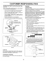
TO CLEAN BATTERY AND TERMINALS -
TRAILING
EDGE UP
Corrosion and dirt on the battery and terminals can cause
the battery to "leak" power.
o
Remove terminal guard.
o
Disconnect BLACK battery cable first then RED bat.
tery cable and remove battery from tractor.
o Wash battery with solution of four tablespoons ol
baking soda to one gallon of water. Be careful not tOge_
the soda solution into the celts.
FLAT WASHER
LOCK
HEX BOLT (GRADE 8)*
*A GRADE 8 HEAT TREATED 80LT CAN 8E
IDENTIFIED BY SIX LINES ON THE BOLT HEAD.
o
•
FiG. 10
TO SHARPEN
BLADE
(See Fig. 11)
Care should be taken to keep the blade balanced. An
unbalanced blade will cause excessive vibration and eventual damage to mower and engine,
Keep battery and terminals clean.
Keep battery bolts tight.
!5
o
o
Rinse the battery with plain water and dry.
Clean terminals and battery cable ends with wire brush
until bright.
Coat terminals with grease or petroleum jelly.
Reinstall battery (See "INSTALL BATTERY" in As_
sembly section of this manual).
CUSTO
TRANSAXLE
t3 & 14)
PUMP
RESPONSI
ENGINE
FLUUD LEVEL (See Figs,
LUBRMCATION
Check fluid level after every 25 hours of use, Rear drawbar
must be removed to check fluid level°
+
Remove the four (4) fasteners to remove the drawbar.
•
Clean reservoir thoroughly before removing cap.
+
Check for,proper fluid+ level in reservoir (should be
above the OiL LEVEL COLD" line).
-
If oil is needed, remove cap on reservoir (with a
clockwise rotation), and fill to "OIL LEVEL COLD" line
with SAE 10W30 oil.
.
Replace cap securely (do not overtighten).
•
Reassemble drawbar and tighten fasteners securely.
LITIES
Change the oil after the first two hours of operation and
every 25 hours thereafter or at least once a year if the
tractor is not used for 25 hours in one year,
Check the crankcase oil level before starting the engine
and after each eight (8) hours of continuous use. Add SAE
30W motor oil or equivalent. Tighten oil fi!t cap/dipstick
securely each time you check the oil level, SAE 5W-30
motor oil may be used to make starting easier in areas
where temperature is consistently 32 ° F or lower.
TO CHANGE ENGINE OIL (See Fig+ 15)
Determine temperature range expected before oil change.
All oil must meet API service classification SG.
COOLING FAN
+
Be sure vehicle is on level surface.
•
,
Oil will drain more freely when warm.
Catch oil in a suitable container.
+
Remove oil fill dipstick. Be careful not to allow dirt to
enter the engine when changing oiL
+
Remove drain plug.
-
After oil has drained completely, replace oil drain plug
and tighten securely.
•
Refill engine with oil through oil fill dipstick tube, Pour
slowly. Do not overfil!. For approximate capacity see
Product Specifications on page 3 of this manual,
"
Use gauge on oi! fill dipstick for checking level. Be sure
dipstick cap is tightened securely for accurate reading.
Keep oil at "FULL" fine on dipstick.
SAE VISCOSITY GRADES
FIG. 13
FASTENERS
"_,
°F
+20°
0+
30°
.+,o° +4°
TEMPERATURE
A+r coofed engines
32_ 40°
+°
60=
80+
100=
,'o+
_°
BEFORF
NF+XT OIL CHANGE
sng+nss<
Use ef m t_lti*v_scos;ty o++s
RANGE ANTICIPATED
run hotter than e_omet}ve
+,o° +,o°
(10W-30, etc. above 40_F (++C)wilt result in high oil consumptbn and pessibte
engine damage.
FASTENERS
Check oil feve_more
fequent+y if using these types of oils.
** SAE 30 <_+I,if use_ be_c_, 40°F(4°0)
witt result in I'_,td starting and pessib_e engine
_ore _am&qe _Je to naaeQuate lubrication,
DRAWBAR
-.-"-'_"_
AIR SCREEN
FIG, 14
V-BELTS
Check V-belts for deterioration and wear after 100 hours
and replace if necessary. The belts are not adjustable,
Replace belts if they begin to slip from wear.
TRANSAXLE
OIL FILL
CAP/DIPSTICK
+
/
OIL DRAIN PLUG
COOUNG
Keep transaxfe free from build-up of dirt and chaff which
can restrict cooling.
FiG, 15
16
'
CUSTO
..... i
ABR FILTER
FOAM
E
PRE-OLEANER
RESPONSI
(See Fig.
z
LtTtES
SCREWS
t6)
_r
BLOWER HOUSING
SCREWS
Your engine will not run properly and may be damaged by
using a dirty air filter, Cfean the foam pre-cleaner element
after every 25 hou rs of operation, more often if used in very
dusty, dirty conditions.
o
Remove knob and cover.
o
Remove cartridge nut and replace cartridge.
o
Reassemble and tighten securely.
NOTE.: Do not attempt to clean or oii the paper cartridge.
Replace paper cartridge once a year or after every I00
hours of operation, more often if used in very dusty, dirty
conditions.
,
Wash foam pre-cteaner in liquid detergent and water.
,
Wrap foam pre°cleaner in cloth and squeeze dry.
o
Lightly coat foam preocleaner with clean engine oil.
Squeeze in towel to remove excess oit. Do not saturate.
,
-
ENGINE COOMNG
FiG. t7
InstaII foam pre-cleaner over paper cartridge.
Reassemble cover and secure with knobs.
COVER
KNOB _--
MUFFLER
Inspect and replace corroded muffler and spark arrester (il
equipped) as it could create a fire hazard and/or damage.,
__.....,._z_
T
SPARK
_L.S
FOAM
/
PREoCLEANER
i
JL .
_'i'-,..__AgR
IN-LINE
PAPER
CARTRIDGE
CLEANER
BASE
(See Fig. I5)
The engine air screen must be kept free of dirt and chaff to
prevent engine damage from overheating. Clean with a
wire brush or compressed air to remove dirt and stubborn
dried gum fibers.
COOUNG
FUEL FBLTER
(See Fig. 18)
Fuel filter should be replaced once each season, if fue_filte_
becomes clogged, obstructing fuel flow to carburetor, re,,
placement is required,
FiG, 16
ENGINE
PLUGS
Replace spark plugs at the beginning of each mowin!;
season or after every 100 hours of use, whichever come_
first. Spark plug type and gap setting is shown in "PROD ._
UCT SPECIFICATIONS" on page 3 of this manual.
COVER
AIR SCREEN
FIiNS
=
With engine coot, remove filter and plug fuel ]in<;
sections,
,
Place new fuel filter in position in fuel line.
o
Be sure there are no fuel line leaks and clamps arc
properly positioned,
o
Immediately wipe up any spilled gasoline,
FILTER
FINS (See Fig. t7)
F_G. 18
Remove any dust, dirt or oil from engine cooling fins to
prevent engine damage from overheating,
CLSANING
,
Remove oil fill dipstick and cover opening to prevent
entry of dirt,
o
Clean engine, battery, seat, finish, etc. of all foreign
matter.
•
Remove screws from blower housing and lift housing
off engine.
,
Keep finished surfaces and wheels free of al! gasoline,
oil, etc,
•
Remove the screws securing the starter housing and
lift housing off engine,
•
Protect painted surfaces with automotive type wax.
o
Use compr_ssed air or stiff bristle brush to thoroughly
clean engin_ cooling fins.
o
To reassembi
_reverse above procedure.
t7
We do not recommend using a garden hose to clean you_I
unit unless the electdcaf system, muffle_, air filter and
carburetor are covered to keep water out. Water in engin_
can result in a shortened engine lifeo
ERVICE AN
CAUTION:
ADJUSTM
TS
BEFORE PERFORMING ANY SERVICE OR ADJUSTMENTS:
•
Depress
o
Place motion control lever in "NEUTRAL"
clutch!brake
pedal fully and set parking brake.
o
Place attachment clutch in "DISENGAGED"
Turn ignition key "OFF" and remove key.
o
•
Make sure the blades and all moving parts have completely stopped.
Disconnect spark plug wire from spark plug and place wire where it cannot come in contact with
plug,
position.
position.
TRACTOR
TO REMOVEMOWER
CLUTCH
ROD
(See Fig. 19)
Mower will be easier to remove from the right side of unit.
,
o
Place attachment clutch in "DISENGAGED" position.
Move attachment lift lever forward to lower mower to its
lowest position.
•
Roll belt off engine puItey,
o
Disconnect clutch rod from clutch lever by removing
retainer spring.
o
Disconnect suspension arms from rear deck brackets
by removing retainer springs.
,
Disconnect front links from deck by removing retainer
springs.
o
Raise lift lever to raise suspension arms. Slide mower
out from under tractor.
RETAINER
SPRINGS
\
\
iMPORTANT:
IF AN ATTACHMENT
OTHER THAN THE
MOWER tS TO BE MOUNTED
TO THE TRACTOR,
THE
R.H. AND L.H. SUSPENSION
ARMS MUST BE REMOVED
FROM TRACTOR.
TO iNSTALL
MOWER
(See Fig. 19)
-
Raise attachment lift lever to its highest position.
o
Slide mower under tractor with discharge guard to right
side of tractor.
,
o
Lower lift lever to its lowest position.
Install mower in reverse order of removal instructions.
ENGINE
PULLEY
FiG. 19
18
ADJUSTMENTS
SERVICE AN
-i
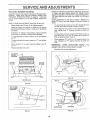
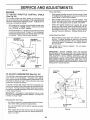
TO LEVEL MOWER
HOUSING
FRONT-TO-BACKADJUSTMENT
(See Figs. 22 and 23) To obtain the best cutting results, the mower housin_
should be adjusted so that the front is approximately 3/8" tc
!/2" lower than the rear when the mower is in its highes'
position,
Check adjustment on right side of tractor. Measure dis.
tance "D" at front and rear flanges of mower housing a_
shown,
Adjust the mower while tractor is parked on levet ground or
driveway.
Make sure tires are properly inflated (See
PRODUCT SPECIFICATIONS
on page 3). if tires are
over or under inflated, you wiil not properly adjust your
mower.
SIDE-TO-SIDE ADJUSTMENT (See Figs. 20 and 21) •
Raise attachment lift iever to its highest position.
o
To lower front of mower turn nut "E" counterclockwis<_
on both front links an equal number of turns,
•
Measure height from bottom of deck curt to ground
level at front corners of mower. Distance "A" should be
the same.
o
•
If distance "A" needs to be changed, snap out access
hole cover on left side of tractor above footrest.
When distance "D" is 3/8" to 1/2" lower at front tha¢_
rear, tighten nuts "F" against trunnion on both fron'
links,
°
.
To raise left side of mower, loosen nut "B" and tighten
nut "C".
To raise front of mower, loosen nut"F" from trunnion or
both front links, Turn nut "E" clockwise on both fron'
links an equal number of turns,
o
To lower left side of mower, loosen nut "C" and tighten
nut "B",
o
When distance "D" is 3/8" to t/2" lower at front tha_
rear, retighten nut "F" against trunnion on both fron'
links.
•
When distance "A" is equal, securely tighten nuts "B"
and "C",
•
Replace access hole cover,
IMPORTANT:
WHEN
ADJUSTING
FRONT
L_INP:
TRUNNIONS,
ALWAYS ADJUST BOTH
EQUALLY
SC
MOWER WILL STAY LEVEL SIDEoTO-SIDE.
,
Recheck sideoto-side adjustment,
\
\
o
o
o
BOTTOM
OF CURL
/
T "D"
"D';
\
GROUND
LiNE
FIG. 20
t_C
{1
flBII
FRONT LmNKS
TRUNNION
FiG. 23
FIGo 21
19
SERVICE AN
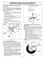
TO REPLACE
.....
MOWER
BLADE
DRIVE
ADJUSTMENTS
BELT
WITH PARKING
i
BRAKE
"ENGAGED"
(See Fig. 24)
....... i
The mower blade drive belt may be replaced without
tools. Park the tractor on levet surface, Engage parking
brake. For assistance, there is a belt installation guide
deca! on the mower housing.
BELT REMOVAL •
°
Place attachment clutch in "DISENGAGED" position.
Move attachment lift lever forward to lower mower to
its lowest position.
•
Roli belt off engine putley.
o
DisconnectR.H.
suspension arm from rear deck
brackel by removing retainer spring.
,
Work belt off both mandrel pulleys and idler pulleys.
"\,..
i/
NUT "A"
fAM
o Pull belt away from mower.
BELT INSTALLATION o install new belt in reverse order of removal.
•
NUT
OPERATING
Make sure belt is in all pultey grooves and inside all
belt guides.
FIG, 25
MANDREL
R.H. SUSPENSION
ARM
ENGINE PULLEY
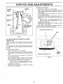
TO REPLACE MOTION
Figs, 26 & 27)
PULLEY _%
RETAINER
SPRING
o
Rotate clutch assembly enough to altow belt to be
removed downwards off engine pulley, under belt
keeper, and around _lutch assembly.
•
Remove belt carefully upwards from transmission
input pulfey and over cooling fan blades.
•
Install new belt by reversing above procedure,
iMPORTANT:
REPLACE ONLY WiTH BELT LISTED
tN THIS MANUAL°
/
MANDREL
PULLEY
FiG, 24
BRAKE
BELT (See
Park the tractor on level surface. Engage parking brake.
For ease of service, remove rear drawbar from chassis
and belt keeper from transmission
input pulley.
For
assistance, there is a belt installation guide decal on
bottom side of left footrest.
•
Remove mower (See "TO REMOVE MOWER" in this
section of this manual).
,
Remove belt from stationary idler and clutching idler.
°
Remove clutch locator.
•
Disconnect ctutch wire harness.
PULLEYS
TO ADJUST
DRIVE
(See Fig, ,!5)
BELT KEEPE_
Your unit is equipped with an adjustable brake system
which is mounted on the right side of the transaxle.
FAN
If unit requires more than six (6) feet stopping distance at
high speed in highest gear, then brake must be adjusted.
t
•
Depress clutch_brake pedal and engage parking brake.
,
Measure distance between brake operating arm and
nut "A" on brake rod.
o
If distance is other than 1-112", disengage parking
brake, loosen jam nut and turn nut "A" until distance
becomes 1-1/2% Retighten jam nut against nut "A"o
o
Engage parking brake and recheck distance,
°
Road test unit for proper stopping distance as stated
above. Readjust if necessary, If stopping distance is
still greater than six (6) feet in highest gear, further
maintenance is necessary. Contact your nearest authorized service center.
Fill, 26
2O
SERVICE AN
ADJUSTMENTS
REVERSE ADJUSTMENT,
Drive unit in reverse on a level surface.
Move motion control lever to the right and forward
until it stops against reverse adjustment plate and
release lever.
•
If unit "creeps" forward or backward, turn engine off
and set parking brake.
,
Loosen and move reverse adjustment plate in th_
same manner as forward adjustment plate described
above:
Forward "creep", move plate backwards 1/16 inch.
Reverse "creep", move plate forward t/16 inch.
•
Retighten bolts securely.
•
Repeat reverse drive test and, if necessary, readjus!
until "creep" is eliminated,
tf "creep" cannot be eliminated by the above adjustments
contact your nearest Sears Service Center,
CLUTCH
LOCATOR
ELECTRIC ._
CLUTCH
PULLEY
E
CLUTCHING
IDLER
STATIONARY
IDLER
"
ELECTRmC
CLUTCH
WiRiNGHARNESS
CONNECTOR
FORWARD
ADJUSTMENT
PLATE
\
BOLTS
FiG, 27
TO ADJUST
MOTION
CONTROL
LEVER
(See Fig. 28)
"NEUTRAL" position of the motion control lever has been
preset at the factory and adjustment should not be necessary,
tf your unit tends to 'icreep" when the motion controt lever
is in "NEUTRAL" position, adjust the neutral lever position
as follows:
FORWARD ADJUSTMENT"
Drive unit forward on a level surface.
•
Move motion control lever to the left and back until
it stops against forward adjustment plate and release
lever.
•
if unit "creeps" forward or backward, turn engine off
and set parking brake.
•
From underside of fender, loosen the two (2) bolts
securing forward adjustment plate and move plate
1/16" opposite the direction the unit "creeps":
Forward "creep", move plate backwards 1/16 inch,
Reverse "creep", move plate forward 1/16 inch.
°
Retighten bolts securely.
o Repeat forward drive test and, if necessary, readjust
until "creep '_ is eliminated.
REVERSE ADJUSTMENT
PLATE
FiG. 28
2I
MOTION
CONTROL
LEVER
SERVICE AN
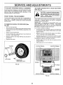
TO ADJUST
STEERING
WHEEL
ADJUSTMENTS
ALIGNMENT
TO START ENGINE WiTH A WEAK
(See Fig. 30)
If steering wheel crossbars are not horizontal (left to right)
when wheels are positioned straight forward, remove
steering wheel and reassemble per instructions in the
Assembly section of this manual.
FRONT
WHEEL
CAUTMON: Lead-acid batteries generate explosive gases, Keep sparks, flame
and smoking materials away from batteries,
Aiways wear eye protection
when around batteries,
TOE-IN/CAMBER
The front wheel toe-in and camber are not adjustable on
your tractor. If damage has occurred to affect the front
wheel toe-in or camber, contact your nearest authorized
service center.
TO REMOVE
Fig, 29)
*
WHEEL
FOR REPAIRS
If your battery is too weak to start the engine, it should be
recharged.
If "jumper cables" are used for emergency
starting, follow this procedure:
IMPORTANT:
YOUR UNIT IS EQUIPPED WITH A t2
VOLT NEGATIVE GROUNDED SYSTEM. THE OTHER
VEHICLE MUST ALSO BE A 12 VOLT NEGATIVE
GROUNDED SYSTEM. DO NOT USEYOURTRACTOR
BATTERY TO START OTHER VEHICLES.
TO ATTACH JUMPER CABLES -
(See
Block up axle securely.
Remove axle cover, retaining ring and washers to allow
wheel removal (rear wheel contains a square key - Do
not lose).
,
Repair tire and reassemble.
,
On rear wheels only: align grooves in rear wheel hub
and axle. Insert square key.
o
Replace washers and snap retaining ring securely in
axle groove.
,
Replace axle cover.
BATTERY
,
Connect each end of the RED cable to the POSITIVE
(+) terminal of each battery, taking care not to short
against chassis.
•
Connect one end of the BLACK cable to the NEGATIVE (-) terminal of fully charged battery,
•
Connect the other end of the BLACK cable to a good
CHASSIS GROUND, away from fuel tank and battery.
TO REMOVE CABLES, REVERSE ORDER
,
-
WASHERS
BLACK cable first from left side of chassis and fully
charged battery.
RED cable last from both batteries.
POS|TIVE TERM|NAL
NEGATIVE
TERMINAL
RETAiNiNG
RING
Q
!
AXLE COVER
'_
SQUARE
KEY
(REAR WHEEL ONLY)
FIG, 29
CABLES
CHARGED
BATTERY
POSiTiVE TERMINAL
NEGATWE
FIG. 30
22
TERMINAL
SERVICE AND ADJUSTMENTS
...... i
TO REPLACE
TO REMOVE
FUSE (See Fig, 31)
HOOD AND GRILL
_/
Replace with 30 amp automotive-type plug-in fuse. The
fuse holder is located in the engine compartment, directly
in front of the dash.
I
CAUTION:
Muffler
is hot.springs
Be careful
when
removing
retainer
from
i!
i_i_
hood pivot brackets,
i
°
Raise hood.
t
Unsnap headlight wire connector.
°
Remove retainer springs from hood pivot brackets.
=
Stand in front of tractor.
Grasp hood at sides, tilt
forward and lift off of tractor.
•
To reinstall, slide hood pivot brackets into slots in
frame. Replace retainer springs.
•
Reconnect headlight wire connector and close hood.
HEADLIGHT
CONNECTOR
HOOD
\
FiG. 3i
TO REPLACE
HEADLIGHT
BULB
°
Raise hood,
o
Pull bulb holder out of the hole in the backside of the
grill.
°
Replace bulb in holder and push bulb holder securely
back into the hole in the backside of the grill.
Close hood.
°
iNTERLOCKS
AND RELAYS
Loose or damaged wiring may cause your tractor to run
poorly, stop running or prevent it from starting.
o
(See Fig. 32}
Check wiring. See electrical wiring diagram in Repair
Parts section of this manual.
REMOVE
RETAINER
SPRINGS
FiG. 32
23
SERVICE AN
ADJUSTMENTS
ENGINE
FINAL SETTING -
TO ADJUST THROTTLE
(See Fig. 33)
..... i
CONTROL
CABLE
The throttle control has been preset at the factory and
adjustment should not be necessary, Check adjustment as
described below before loosening cable, tf adjustment is
necessary, proceed as follows:
•
With engine not running, move throttle control lever
from "SLOW" to "CHOKE" position. Slowly move lever
from "CHOKE" to "FAST" position.
o
Check that holes "A" in governor control lever and hole
in governor plate line-up, If holes "A" are not aligned,
Ioosen clamp screwand move throttle cable until holes
are aligned. Tighten clamp screw securely,
•
Start engine and allow to warm for five minutes. Make
finat adjustments with engine running and shift/motion
contro! lever in "NEUTRAL" position.
•
Move throttle control lever to "SLOW" position. With
finger, rotate and hold throttle lever against idle speed
screw. Turn idle speed screw to attain 1750 RPM.
•
While still holding throttle lever against idle speed
screw, turn idle mixture valve in (clockwise) until engine begins to die and then turn out (counterclockwise)
until engine runs rough. Turn valve to a point midway
between those two positions. Release throttle Jever.
ACCELERATION
"
GOVERNOR
CONTROL LEVER
GOVERNOR
CONTROL PLATE
TEST -
Move throttle control lever from "SLOW" to "FAST"
position. If engine hesitates or dies, turn idle mixture
valve out (counterclockwise) 1/8 turn. Repeat test and
continue to adjust, if necessary, until engine accelerates smoothly.
High speed stop is factory adjusted.
damage may result.
Do not adjust -
iMPORTANT:
NEVER
TAMPER
WtTH THE ENGINE
GOVERNOR,
WHICH IS FACTORY
SET FOR PROPER
ENGINE SPEED. OVERSPEEDtNG
THE ENGINE ABOVE
THE
FACTORY
HIGH
SPEED
SETTING
CAN
BE
DANGEROUS.
iF YOU THINK THE ENGINE-GOVERNED
HIGH SPEED NEEDS
ADJUSTING,
CONTACT
YOUR
NEAREST AUTHORIZED
SERVICE CENTER, WHICH HAS
PROPER EQUIPMENT
AND EXPERIENCE
TO MAKE ANY
NECESSARY
ADJUSTMENTS.
HOLES "A"
CLAMP
SCREW
THROTTLE
CABLE
FIG, 33
TO ADJUST
CARBURETOR
THROTTLE
LEVER
IDLE SPEED
SCREW
(See Fig. 34)
The carburetor has been preset at the factory and adjustment should not be necessary. However, minor adjustment may be required to compensate for differences in fuel,
temperature, altitude or load. If the carburetor does need
adjustment, proceed as follows:
tn general, turning idfe mixture valve in (clockwise) decreases the supply of fuel to the engine giving a leaner fuel/
air mixture. Turning the idle mixture valve out (counterclockwise) increases the supply of fuel to the engine giving
a richer fuel/air mixture.
iMPORTANT:
DAMAGE TO THE NEEDLE
TH E SEAT IN CARBURETOR
MAY RESULT
TURNED tN TOO TIGHT.
PRELIMINARY
VALVE
AND
IF SCREW IS
SETTING
•
Air cleaner assembly must be assembled tothe carburetor when making carburetor adjustments.
,
Be sure the throttle control cable is adjusted properly
(see above).
•
With engine off turn idle mixture valve in (clockwise)
closing it finger tight and then turn out (counterclockwise) I full turn.
IDLE MIXTURE
VALVE
FIG. 34
24
STORAGE
ENGINE
immediately prepare your tractor for storage at the end of
the season or if the unit will not be used for 30 days or more.
FUEL SYSTEM
IMPORTANT:
IT iS IMPORTANT TO PREVENT GUM
DEPOSITS FROM FORMING IN ESSENTIAL FUEL
SYSTEM PARTS SUCH AS CARBURETOR, FUEL FILTER,
FUEL HOSE, OR TANK DURING STORAGE.
ALSO,
EXPERIENCE INDICATES THAT ALCOHOL BLENDED
FUELS (CALLED GASOHOL OR USING ETHANOL OR
METHANOL) CAN ATTRACT MOISTURE WHICH LEADS
TO SEPARATION AND FORMATION OF ACIDS DURING
STORAGE.
ACIDIC GAS CAN DAMAGE THE FUEL
SYSTEM OF AN ENGINE WHILE IN STORAGE.
CAUTION: Never store the tractor with
gasoline in the tank inside a building
where fumes may reach an open flame
or spark. Allow the engine to cool
before storing in any enclosure.
TRACTOR
Drain the fuel tank.
Remove mower from tractor for winter storage. When
mower is to be stored for a period of time, clean it thoroughly, remove all dirt, grease, leaves, etc. Store in a
clean, dry area.
°
"
Clean entire tractor (See "CLEANING" in the Customer
Responsibilities section of this manual).
o
•
inspect and replace belts, if necessary (See belt replacement instructions in the Service and Adiustments
section of this manual).
,
Lubricate as shown in the Customer Responsibilities
section of this manual,
-
Be sure that atl nuts, bolts and screws are securely
fastened. Inspect moving parts for damage, breakage
and wear. Replace if necessary.
o
Touch up all rusted or chipped paint surfaces; sand
lightly before painting.
Start the engine and ,e,
' ' it run until the fuel lines and
carburetor are empty.
Never use engine or carburetor cleaner products in the
fuel tank or permanent damage may occur.
Use fresh fue! next season.
NOTE: Fuel stabilizer is an acceptable alternative in
minimizing the formation of fuel gum deposits during storage. Add stabilizer to gasoline in fuel tank or storage
container. Always follow the mix ratio found on stabilizer
container. Run engine at least I0 minutes after adding
stabilizer to allow the stabilizer to reach the carburetor. Do
not drain the gas tank and carburetor if using fuel stabilizer.
ENGINE
OIL
Drain oil ('with engine warm) and replace with clean engine
oil. (See "ENGINE" in the Customer Responsibilities
section of this manual).
BATTERY
•
Fullycharge thebattery
forstorage.
CYLINDERS
°
After a period of time in storage, battery may require
recharging.
•
Remove spark plug(s).
o
,
To help prevent corrosion and power leakage during
long periods of storage, battery cables should be
disconnected and battery cleaned thoroughly (see "TO
CLEAN BATTERY AND TERM INALS" in the Custo met
Responsibilities section of this manual).
Pour one ounce of oil through spark plug hole(s) into
cylinder(s).
•
Turn ignition keyto "START" position for a few seconds
to distribute oil.
•
Replace with new spark plug(s).
,
After cleaning, leave cables disconnected and place
cables where they cannot come in contact with battery
terminals.
OTHER
,
Do not store gasoline from one season to another.
*
Be sure battery drain tube is securely attached.
•
Replace your gasoline can if your can starts to rust.
Rust and/or dirt in your gasoline wil! cause problems.
°
If possible, store your unit indoors and cover it to give
protection from dust and dirt.
o
Cover your unit with a suitable protective cover that
does not retain moisture. Do not use plastic. Plastic
cannot breathe which allows condensation to form and
wilt cause your unit to rust.
IMPORTANT: NEVER COVER TRACTOR WHILE ENGINE
AND EXHAUST AREAS ARE STILL WARM.
25
TROU
G POINTS
LESHOOTI
PROBLEM
CAUSE
Will not start
1.
Out of fuel,
2.
3,
4,
5,
6.
7,
Engine not "CHOKED"
Engine flooded.
Bad spark plug.
Dirty air filter,
Dirty fuel fi_ter.
Water in fuel
CORRECTION
t.
Fitlfuel tank.
properly.
2.
3.
4,
5.
6.
7.
See TO START ENGINE in Operation section,
Wait several minutes before attempting to start.
Replace spark plug.
Ctean/replace air filter,
Replace fuel filter.
Drain fuel tank and carburetor, refill tank with fresh
8.
9,
t0.
Loose or damaged wiring.
Carburetor out of adjustment,
Engine valves out of adjustment,
8.
9.
10.
Hard to start
t.
2,
3.
4.
5.
6.
7,
8.
Dirty air filter.
Bad spark plug,
Weak or dead battery.
Dirty fuel filter.
Stale or dirty fue!,
Loose or damaged wiring,
Carburetor out of adjustment.
Engine valves out of adjustment,
1,
2.
3.
4.
5.
6.
7,
8.
Engine
1.
2,
3,
4.
5,
Clutch/brake pedal not depressed,
Attachment clutch ts engaged.
Spark plug wire is disconnected.
Weak or dead battery.
Blown fuse.
will not turn over
6.
7,
8,
g.
10,
Engine
start
clicks but will not
Loss of power
Clean/replace air filter.
Replace spark plug.
Recharge or replace battery.
Replace fuel filter.
Drain fuel tank and refill with fresh gasoline.
Check atlwiring.
Contact Sears Service Department,
Contact Sears Service Department.
1.
2.
3.
4.
5.
6.
7.
8,
9,
!0.
Depress clutch/brake pedal.
Disengage attachment clutch.
Connect wire to spark piug.
Recharge or replace battery,
Replace fuse.
Clean battery terminals.
Check all wiring.
Check/replace ignition switch.
Check/replace solenoid or starter,
Contact Sears Service Department.
1.
2.
3.
4.
Weak or dead battery,
Corroded battery terminals.
Loose or damaged wiring,
Faulty solenoid or starter.
1.
2.
3.
4.
Recharge or replace battery.
C_ean battery terminals.
Check all wiring.
Check/replace solenoid or starter.
1.
2.
3,
4.
5.
6.
7.
8.
9,
Cutting too much grass/too fast,
Throttfe in "CHOKE" position,
Build-up of grass, leaves and trash under mower.
Dirty air filter.
Low oil level/dirty oil,
Faulty spark plug.
Dirty fuel filter.
Stale or dirty fuel.
Water in fuel.
t,
2,
3.
4,
5,
6,
7.
8.
9.
Set in "Higher Cut" position/reduce speed.
Adjust throttte control,
Clean underside of mower housing,
Clean/replace air filter.
Check oil _evelichange oil,
Clean and regap or change spark plug.
Replace fue! filter.
Drain fuet tank and refill with fresh gasoline.
Drain fuel tank and carburetor, refill tank with fresh
gasoline and replace fuel filter.
Connect and tighten spark plug wire.
Clean engine air screenflins.
Clean/replace muffler,
Check all wiring.
Contact Sears Service Department.
Contact Sears Service Department.
10.
ti.
12,
13.
!4.
15,
Excessive vibration
Corroded battery terminals,
Loose or damaged wiring.
Faulty ignition switch.
Faulty solenoid or starter.
Faulty opera,or presence switch(as).
gasoline and replace fuel filter,
Check alt wiring,
Contact Sears Service Department.
Contact Sears Service Department,
Spark plug wire loose.
Dirty engine air screen/fins.
Dirty/clogged muffler.
Loose or damaged wiring.
Carburetor out of adjustment.
Engine valves out of adjustment.
t,
2.
Worn, bent or loose blade.
Bent blade mandrel
3.
Loose/damaged
t0.
11.
12,
t3,
14,
15.
1.
2.
3.
part(s),
26
Replace blade, Tighten blade bolt,
Replace blade mandrel,
Tighten loose part(s), Replace damaged parts.
TROU
PROBLEM
.......
i
Engine continues to run
when operator leaves seat
with attachment
eiutch
,\
LESHOOTI
CAUSE
G POINTS
CORRECTION
I.
Faulty operator-safety presence control system.
1.
Check wiring, switches and connections.
If not
corrected, contact Sears Service Department,
1.
2,
Worn, bent or loose blade.
Mower deck not ieveL
i.
2.
Replace blade, Tighten blade bolt.
Level mower deck,
3.
4.
Buitdup of grass, leaves, and trash under mower.
Bent blade mandrel,
3.
4.
Clean underside of mower housing.
Replace blade mandrel,
Mower blades wltl not
rotate
t.
2.
3.
4.
Obstruction in clutch mechanism.
Worn/damaged mower drive belt.
Frozen idlerpulley.
Frozen blade mandrel,
t.
Remove obstruction.
2.
3,
4,
Replace mower ddve belt,
Replace idler pulley.
Replace blade mandrel,
Poor grass dIscharge
t.
2,
3.
4.
5,
6,
Engine speed too slow.
Travel speed too fast.
Wet grass,
Mower deck not level.
Low/uneven tire air pressure.
Worn, bent or loose blade.
1.
2.
3,
4.
Place throttle control in "FAST" position.
Shift to slower speed.
Allow grass to dry before mowing.
Level mower deck.
7.
8.
Buildup of grass, leaves and trash under mower.
Mower drive belt worn.
engaged
Poor Cut - uneven
9.
t0.
Headlight(s) not working
(if so equipped)
Battery will not charge
Tractor "creeps" with
motion control lever in
"neutra!"
Blades improperly installed.
{mproperblades
used.
5.
6,
7,
8,
9.
t0.
Check tires for proper air pressure,
Repiaceisharpen blade. Tighten blade bolt.
Clean underside of mower housing.
Replace mower drive belt.
Reinstall blades sharp edge down.
Replace with blades listed in this manual
1.
Switch is "OFF".
1.
Turn switch "ON".
2.
3.
4.
5.
Bulb(s) burned out.
Faulty light switch,
Loose or damaged wiring,
Blown fuse.
2,
3.
4.
5.
Replace bulb(s).
Check/replace light switch,
Check widng and connections.
Replace fuse.
1.
2.
Bad battery' cell(s).
Poor cabte connections.
1.
2.
Replace battery,
Check/clean all connections.
3.
4.
Faulty regulator (if so equipped),
Faulty alternator.
3.
4.
Replace regulator.
Replace alternator.
1.
Motion control lever is out of adjustment.
1.
Adjust motion control lever.
position
27
12.5 HP 38" RiDiNG
LAWN TRACTOR
== MODEL NUMBER
917.255590
SCHEMATBC
olI!o
lil
z
°
B cK
BATTERY
[
---....
RED
ReD
FUSE 3OAMP.
I
i
__
_
I
WHITE
a
i ......
4
I
_-E
I
i
i
WHtTE
SOLENOID
"if
I
ATT'MENT
CLUTCH
(CLUTCH
OFF)
Lj'T_
I
,,"_EJiL
I
(PEDAL UP)
l
CLUTCH/BRAKE
I
I
BLACK
•
BLACK
BLACK
SEAT
SWITCH
(NOT OCCUPIED)
O
O
.(_"I
BLACK
IGNITION
L--_-_-'_
T..............
J
"J
SPARK
O
PLUG O .............
I
RED
/ '_DIOD_E
M
3 AMPS DC
POSITION
SWITCH
CIRCUIT
OFF
M + G
ON
B+L
START
.... O---'-
B + S
NON-REMOVABLE
CONNECTIONS
ORANGE
YOUR TRACTOR IS EQUIPPED
WITH A SPECIAL ALTERNATOR
SYSTEM. THE LIGHTS ARE NOT
CONNECTED TO THE BATTERY,
BUT HAVE THEIR OWN
ELECTRICAL SOURCE.
BECAUSE OF THIS, THE BRIGHTNESS OF THE LIGHTS WILL
CHANGE WITH ENGINE SPEED.
AT 1DLE THE LIGHTS WILL DIM.
AS THE ENGINE IS SPEEDED UP,
THE LIGHTS WILL BECOME
THEI R BRIGHTEST.
--_----
\" 20 VOLTS AC (MIN,)
IN LIN_
NOTE
IGNITION
ALTER NATOR
""
@ 3600 RPM
(BATTERY
_-_'_'\
REMOVABLE
CONNECTIONS
28
,
ALTERNATOR
" _ AMPS
@ 11 VOLTS AC @ 3600 RPM,
i HEAD
LIGHTS
WIRING INSULATED CLIPS
NOTE: If wiring insulated clips were removed for servicing of unit, they should
be replaced to properly secure your wiring.
REPAmRPARTS
12=5 HP 38" RIDING
LAWN TRACTOR
.. - MODEL
NUMBER
917o255590
DECALS
t3
6
!8
3
7 8
8
7 4
13
10
9
t5
11
t6
!2
KEY PART
NO, NO.
1
2
3
4
5
6
7
8
9
DESCRIPTION
108456X
127908
124489X
124490X
132674
!33644
128235
108631X
125880X
WHEELS
Decal
.Decal
Decal
Decal
Decal
Decat
Decal
Decal
Decal
Instruction Operat Eng
Eng 12 5hp lc Gold Craft
Hood Slope Rh Craftsman
Hood Slope Lh Craftsman
Grille Lt4000 Craft Usa
Maint Customer Sears Dora
Panel Side l/c Gofd/blk
li(die Cut)
Fender Craftsman Red
KEY PART
NO. NO.
DESCRIPTION
10
11
!2
13
14
t5
16
17
18
19
Decal Caution English
Decal Clutch/brake English
Decal V-belt Sch Tractor Eng
Decal Chassis 38" Hydro
Decal Mower Drive Schematic 38
Decal Danger English
Decal Rota Blades English
Decal Mower Qc System
Decal lnsr Wh Strg Crafts Usa
Manual Owners 255590 Eng
t06974X
4900J
t2t215X
I20!66X
130929
121343X
3713J
133179
132267
t332!6
AND TIRES
1 -....._.._.._=. _
7
3,9
KEY PART
NO. NO,
DESCRIPTION
t
2
3
4
5
6
7
8
9
10
1!
Cap Value Tire
Stem Value
Tire F Ts 15 X 6 0 - 6 Service
Tube Front (Service ftem Only)
Rim Asm 6"front Silver Service
Fitting Grease (Front Wheel Only)
Bearing Flange (Front Wheel Only)
Rim Asm 8"rear Silver Service
Tire R Ts 18x8 5-8 S Service
Tube Rear (Service Item OnBy)
Cap Axle Blk 1 50 X 1 00
59t92
65139
106222X
59904
106732X36I
278H
9040H
!06108X361
3588R
7152J
104757X
NOTE:
29
AIf component dimensions given in U,S. inches
1 inch = 25,4 mm
REPAIR PARTS
12.5 HP 38" RIDING LAWN TRACTOR
ELECTRICAL
34
- - MODEL NUMBER
33
34
33
9!7.255590
A
t3
C
D
@12 _ 13
f
I
@14
I
/
\
t
t
}
f
I
I
l
I
I
l
t
\
I
29
t t
/
I/
1
-~
,_
17
2
16
J
36
\
\
6
\
/
\
7
!
/
22
L
/
1
/
1
/
\
27
1
J
"
t
41
(
28
/
i
24
2O
I
I
_
s
i_ t
_
ill
k,d
t'
21
19
3o
i
31
30
REPAIR PARTS
12,5 HP 38" RIDING LAWN TRACTOR
......
!
.. ,. MODEL NUMBER
ELECTRICAL
KEY PART
NO. NO.
1
2
3
4
5
6
7
8
9
t0
11
12
13
14
15
16
t7
18
19
20
21
22
23
24
25
26
27
28
29
30
3i
32
33
34
35
36
126664X
130890
108236X
128369
4207J
132202
4799J
129965
109596X
t09081X
STD551125
73350400
74780408
STD551225
STD541425
131563
109553X
STD601005
STD365402
123620X
12421tX
t2!305X
121264X
74760412
STD551025
STD551125
STD54t025
109310X
108824X
105687X
124083X
tI07t2X
127441X
7662J
STD601005
104445X
DESCRiPTiON
Battery 12v 25amp Lt Hyd Craft
Bracket Switch _ntedock
Bracket Switch Clutch
Harness tgn B&s Fender HI
Cable Ground 6ga 12"black
Cable Battery 6 Ga 42"red
Cable Battery 6ga 11 "red
Case Battery Hinge Mechanical
Clamp Hose Olive
Solenoid
* Lockwasher
Nut Jam Hex 1/4-20 Unc
Bolt Fin Hex 1i4-20uncxli2 Gr5
* Washer
* Nut
Cover Terminal Red
Switch Inttk Clutch Red 4 Term
* Screw
* Starter Swtc
Cover Sw Key Blk t 25 Text Sit
Nut ignition
Switch Plunger Nc Gray
Caps Battery 25/30 Amp
Bolt Hex Hd 1/4-20unc X 3/4
* Washer
* Washer
* Nut
Key lgn Molded Craftsman
Fuse 30 Amp Auto Green
Tube Plastic 9"
Cover Sw Jgn BIk 6 00 X 1 580
Switch Light Blk Btk Red
Harness Socket Light
Bulb Light #1141
* Screw
!nterlock Switch
* STANDARD HARDWARE -- PURCHASE LOCALLY
NOTE: All component dimensions given in U.S. inches
1 inch = 25.4 mm
31
917.255590
REPAIR PARTS
12.5 HP 38" RiDiNG
CHASSIS
LAWN TRACTOR
- .- MODEL
NUMBER
917.255590
AND ENCLOSURES
2_
10
28
18
38
17
3O
13
31
33
37
H
34
A
E
B
G
7
H
I
K
24
3
36
32
@26
L
27
32
REPAIR PARTS
12,5 HP 38" RiDiNG
CHASSB
LAWN TRACTOR
o ,_rT_ODEL NUMBSR
AND ENCLOSURES
KEY PART
NO. NO,
I
2
3
4
5
6
7
8
9
I0
11
!2
t3
I4
15
I6
t7
18
19
2O
2t
22
23
24
25
26
27
28
29
30
3I
32
33
34
35
36
37
38
131050
127866
17490612
STD523707
STD54!437
I26595X010
17490608
275tR
126604X0t0
5479J
t22795X
12t794X
124031X012
1749O612
74180512
STD54!431
t3t445X4!7
t26938X
STD512505
STD551125
122933X
t24479X
4921 H
STD523707
19131312
STD54t437
17490608
123915X
I24029X
126599X417
109873X
t7490612
105465X417
I05464X417
STD533707
STD541437
t05466X
I26471X
DESCRIPTION
Chassis Wtdmt Lt/hydifen 38 42
Drawbar Lt/yt t 1 Ga
Screw Thdrot 3/8o! 6x3/4 Ty-tt
* Bolt
* Nut
Saddle Sifkscreened
Screw ThdroJ 3/8-16xl/2 Ty-tt
Clip Line Fuel !3/32 Mtg Hole
Dash Silkscreened Sears Eng
Plug Button Blk 359 Din
Panel Pnt Dash Lh
Cover Access Black Square
Pane! Slkscr Dash Rh Weldment
Screw Thdrol 3/8-I6x3/4 Ty-tt
Screw Mach Trhd 5/t 6-18uncx3i4
* Nut
Hood Asm Pnt Weld Silver Powde
Bumper Hood
*Screw
*Washer
Rivet Ratchet Nylon
Washer Nylon BIk 28x 75x 19
Retainer Spring
* Bolt
Washer 13/32 X I3/16 X 12 Ga
* Nut
Screw Thdro! 3/8-16xl/2 Ty-tt
Grille Grey
Lens Headlight Bar Clear
Fender Pnt
Bracket Pnt Fender
Screw Thdrol 3/8-! 6x3/4 Ty-tt
Footrest Pnt Lh (silver)
Footrest Pnt Rh (silver)
* Bo!t
* Nut
Pad Footrest Rbr Sq Craftsman
Clip lnsuiated 406 Mtg Hole
* STANDARD HARDWARE -- PURCHASE LOCALLY
NOTE: All component dimensions given in U.S. inches
t inch = 25,4 mm
33
917.255590
REPAIR PARTS
12.5 HP 38" RIDING
LAWN TRACTOR
" -' MODEL NUMBER
DRIVE
917,255590
M
N
51
1o3
81
77
/
lOI
34
P 63
53 _
REPAIR PARTS
12o5 HP 38" RHD NG LAWN TRACTOR
° ° MODEL
NUMBER
917.255590
DRHVE
KEY PART
NO. NO.
z
:4
i.
I
2
4
5
6
7
8
t0
1t'
12
13
14
15
16
17
1-8
!9
20
2t
22
23
24
25
26
27
28
29
30
31
32
33
34
35
36
37
38
39
40
41
42
43
44
45
46
47
48
49
50
51
52
53
54
55
KEY PART
NO, NO,
DESCRIPTION
DESCRIPTION
121430X
Pump Hydro Sunstrand
56 STD55t062
*Washer
12143tX
TransaxteAsm
57 STD571810 *Roll Pin
121323X
Pump Resevoir
58 123674X
Pulley tdier Fiat
126581X
Keeper Asm Belt Transaxle
59 STD523727
* Bolt
73680400
Nut Crown!ock 1/4-20 Unc
60 4470J
Spacer Split 395 X 59 Bzp
t26579X
Pulley hput
61 t09070X
Keeper Bett Retainer
121211X
Spacer Stand-off Hydro Fan Zin
62 19131312
Washer 13/32 X 13/I6 X 12 Ga
12t188X
Bracket Pnt Mtg Differential
63 STD541437
*Nut
STD523145
* Bolt
84 t27783
Pulley Idler V Groove Plastic
STD551 t3I
* Lockwasher
65 I23789X
Bellcrank Asm
STD54t431
*Nut
66 123205X
Retainer Belt Style Spring
1t0422X
Spring Return Brake Tia Zinc
67 STD523715 *Bolt
126578X
Fan Hydro 7'
68 STD541437
* Nut
STD522507
* Screw
69 STD551037
*Washer
19092016
Washer 9/32 X 1-1/4 X 16ga
70 105710X
Link Clutch 7 66
STD551125
*Washer
71 STD561210
*Pin
1265%X ......... V Belt Ground Drive 8_i 20 ..................................................................
72 .....i05706X ..........Bearing Nyl 503 X 628 X 1 25
t26912X
Pack Asm Friction
73 1I08t2X
Washer Hardened
128655X
Pin Roll 198 X 866
74 t2000039
Ring Klip #t5304-50
!26589X
Rod Control Bal! J Solid 2 166
75 t05709X
Spring Return Clutch 6 75
73040400
Hex Flange 1/4-28 Unf
76 STD561210 * Pin
STD523707
* Bolt
77 8883R
Cover Pedal Blk Std
STD54t437
*Nut
78 131002
Pulley Engine
STD551 O25 • Washer
79 71130720
Bolt Finhex 7i16-20unfx1 -t/4g8
STD541437
• Nut
8O STD551143 * Washer
12! t89X
Bolt U 3/8-16 X 2 83
81 129921
Keeper Belt Engine Lh Lt
STD541437
• Nut
82 STD523710
* Bolt
106933X
Knob Rd 1/2-I3 Ptstc Thds Blk
83
19132012
Washer t3/32 X 1-I/4 X 12 Ga
126592X
Lever Asm Pnt Control
84 STD541437
* Nut
126590X
Bushing Tin Wit 20 Step Pm
85 !26575X
Arm Pnt Control Lt Hydro
t26591X
Washer Shim 53 X 1 25 X 0598:
86 7605J
Bolt Shoulder t/4 X 20 Unc
STD581050
• E Ring
87 110739X
Washer Spring Oiled
126910X
Spring Extension 3 250 BIk
88 73680400
Nut Crowntock 1/4-20 Unc
73040400
Hex Flange t/4-28 Unf
89 126654X
Control Bypass
132654
Rod Brake 2t 670 Btk Zinc Hydr
90 STD551237 * Washer
STD54!437
*Locknut
91 73610600
Nut Fin Hex 3/8-24 Unf
STD54t237
* Nut
92 I26600X
Console Shift W/ign Lt Hydro
106888X
Spring Rod Brake 2 00 Zinc
93 126597X
Plate Pnt Neutral Adjust Rh
STD551037
*Washer
94 126598X
Plate Pnt Neutral Adjust Lh
4921H
Retainer Spring
95 STD551025 *Washer 17/64
STD624003
* Retainer
96 STD55tt25
* Washer
!28904
Rod Brake Parking Lt
97 STD512505 * Screw
124236X
Cap Parking Brake Red
98 121t99X
Spacer Split 80xl 70 Cad/zinc
126649X
Bracket Transaxte
99 121749X
Washer 25/32 X 1 !/4 X 16 Ga
t 7490616
Screw Thdrof 3/8-t 6 X t Ty-lt
100 STD581075
* E Ring
! 7490612
Screw Thdrot 3/8-t 6x3/4 Ty-tt
101 I23583X
Key Square 2 0 X t845/1865
t 2I 187X
Bracket Mounting Hydro Tia
t02 12t748X
Washer 25/32 X 1 5/8 X t6ga
STD523707 * Bolt
103 13!402
Guido Belt Dr Mower Rh
STD541437 * Nut
104 STD523710 * Bolt
t26577X
Keeper Span Center Lt Hyd Zinc
105 19132012
Washer t3/32 X t-i/4 X t2 Ga
STD541437 * Nut
106 STD541437
* Nut
!22424X
Shaft Asm Pedal Foot t 930
!20!83X
Bearing Nylon Btk 629 ld
* STANDARD HARDWARE - o PURCHASE LOCALLY
NOTE: All component dimensions given in U,S. inches
! inch = 2&4 mm
35
REPAIR PARTS
12.5 HP 38" RIDING
STEERING
LAWN TRACTOR
- - MODEL
NUMBER
ASSISM BLY
42
37
26
27
/
18
35
23
31
24
26
36
43
917.255590
REPAIR PARTS
12.5 HP 38" RIDING
STEERING
LAWN TRACTOR
=.. MODEL NUMBER
ASSEMBLY
KEY PART
NO. NO.
1
2
3
4
5
6
7
8
9
10
1t
12
13
14
15
16
17
18
19
20
21
22
23
24
25
26
27
28
29
30
31
32
33
34
35
36
37
38
39
40
41
42
43
44
45
46
1007t3N
105669X
130460
130459
6266H
121748X
19272016
12000029
3366R
130468
STD551137
73610600
1t0438X
74011056
73601000
132624
132614
57079
124035X
126684X
STD551125
71070410
127501
1098t6X
124036X
12000029
t24034X
6266H
17490612
STD55t137
73610600
130465
120754X
19131416
STD561210
132196
STD611005
100710L
19133808
STD541537
104820X
1244!7X
t21749X
121748X
12000029
121232X
DESCRIPTION
Wheel Steering Std Black
Axle Asm Front
Spindle Asm Lh
Spindle Asm Rh
Bearing Race Thrust Harden
Washer 25/32 X t 5/8 X 16ga
Washer27i32X
1 1/4 X 16 Ga
Ring Klip #t5304-75
Bearing Co_ Strg Blk
Link Drag Sot BaH Jt 20 064
* Lockwasher
Nut Fin Hex 3/8-24 Unf
Spacer Bearing Axle Front
Bolt Hex 5/8-tl Unc X 3-1/2
Nut Hex Jam Lk Wiwh 5/8-11 Unc
Pin Axle 5/8 X 1 55/1 54 Lg
Shaft Asm Strg 5/8 X 15 19 Lt
Washer 'Thrust 515x 750x 033
Support Shaft
Washer Shim 1/4 X 5/8 X 062
* Washer
Screw Hex Socket 1/4-20 X 5/8
Shaft Asm Pittman
Nyliner Snap In
Bracket Steering
Ring Ktip #t5304-75
Gear Sector
Bearing Race Thrust Harden
Screw Thdrol 3/8-t 6x3/4 Ty-tt
* Lockwasher
Nut Fin Hex 3/8-24 Unf
Rod T_e Wire Form t9 75 Mech
Bushing Rod Tie Blk Lt
Washer 13/32 X 7/8 X 16ga
* Pin
Bushing Strg 5/8 Id Dash
* Screw
Insert Cap Strg Whee! Std BIk
Washer 13/32 X 2-3/8 X 8 Ga
* Gripco Nut
Adaptor Wheel Strg 640/635id
Boot Shaft Steering
Washer 25/32 X t t/4 X 16 Ga
Washer 25/32 X 1 5/8 X 16ga
Ring Klip #t5304-75
Cap Spindle Fr Top Blk
* STANDARD HARDWARE o o PURCHASE LOCALLY
NOTE; All component dimensions given in U.S. inches
1 inch = 25,4 mm
37
917,255590
REPAIR PARTS
12.5 HP 38" RIDING
LAWN TRACTOR
.- - MODEL NUMBER
917.255590
ENGINE
I
C
27
\
25
3O
36
F
32
33,/
J
38
37
29
L EQU1PM ENT
ster
c
D
9
E
6
4 1
F
G
5
_
4
_
2
J
7
_7
18
lg
38
REPAIR PARTS
12.5 HP 38" RIDING LAWN TRACTOR
........
i
......... i
- MODEL NUMBER
917.255590
ENGINE
:L
KEY PART
NO. NO,
1 132761
2 177204 t 0
3 131953
4 125610X
5 10!326L
6 17Q30808
7 STD551025
8 STD551125
9 STD522510
10 STD54 t 031
!1
STD55113t
t2
7t O70510
13 125593X
14 13280324
!5
13200300
16 STD551237
17 17490620
18 105736X
19 _105839X
20 ....105838X
21 STD551025
22
123650X
23 128953X *v"
24 STD60'_005
25 124027X
26 17030808
27 105037X
29 121851X
3O t 27057X
31 109202X
32
123549X
33
123487X
34
124028X
35
t 7490412
36 19091416
37 101335K
38
39
40
2751R
STD54t437
DESCRIPTION
Controt Throt Rh Blk Pd114 10
Screw Hex Thd Cut 1/4-20x5/8 T
Engine B&s 12 5 Jcq Dual 1 Vt
Muffler Exhaust B&s Lt Std
Deflector Muffler # 222573
Screw Spidertoc Hexhd#Sxl/2 Ab
* Washer
* Washer
* Bolt
* Nut
* Lockwasher
Screw Hexhd Cap 5/16-18x5/8
Gasket 1 313 Id Tin Plated
Nipple Pipe 3/8 Npt X 3"
Elbow Std 90 Degree 3/8-18 Npt
*Washer
* Screw Thdrot 3/8-16xl -1/4 Tytt
Shield Pnt Heat
Receptacle 1/4 Tur0 Dacrotized
Retainer 1/4 Turn 365odx 222id
* Washer
Stud 1/4 Turn (replaces 10575t
Shield Pnt Heat Browning Grass
* Screw
Shield PntHeat Hood Lt
Screw Spiderloc Hexhd#8xli2 Ab
Strip Foam 18"
Arrestor Spark
Strap Hood
Tank Fuel 1 25 Fr
Cap Asm Fuel Wisym Vented
Clamp Hose BIk
Bushing Snap Nyl Blk Fuel Line
Screw Hexwsh Thdrol 1/4-20x3/4
Washer 9/32 X 7/8 X 16ga
Line Fuel 9 50"
Plug Oil Drain (Ordre From Engine
Manufacturer)
Clip Line Fuel 13/32 Mtg Hole
* Nut
* STANDARD HARDWARE - - PURCHASE LOCALLY
NOTE: All component dimensions given in U.S. inches
I inch = 25.4 mm
39
;_ i_¸
REPAIR PARTS
12.5 HP 38" RIDING LAWN TRACTOR
== MODEL NUMBER
917,255590
38" MOWER
76
37
58
57
24
10
4O
REPAIR PARTS
12.5 HP 38" RIDING LAWN TRACTOR
-- MODEL
NUMBER
917,255590
38" MOWER
KEY
NO.
PART
NO.
1
2
3
4
5
6
129365
73680500
72140506
763tj
!10485X
128774
7
8
9
10
11
12
13
I4
I5
16
17
t8
19
20
21
22
23
24
25
26
27
28
29
129895
133172
127842
129962
10030600
850857
128961
t06736X
106735X
105896X
t10452X
t06734X
19111016
105304X
128772
19111216
78158
4939M
74600636
851074
127218
73350800
130171
73680800
127224
128763
133710
127223
73360700
110447X
73710700
133736
129963
129206
73050900
131494
t22052X
33
34
35
36
37
38
39
40
41
42
43
DESCRIPTmON
KEY
NO.
PART
NOo
44 19131612
45 73680600
46 131290
47 133502
48 133503
49 120183X
50
t22507X
51 105767X
52 125631X
53 t22365X
54 122364X
55 1225t2X
56 122514X
57 t2000002
58 19211416
59 131288
60 131289
61 76020312
62 I3355t
63 133504
64 72t106t4
65 133550
66 73350600
67 133205
68 4497H
69 127498
70 128759
71 133573
72 t06932X
73 121748X
74 t 2000029
75 128903
76 127845
77 127847
78 131870
79 130840
80 174905t2
Mower Asm 38"welded
Nut, Crownlock 5/16-18
Bolt, Carriage 5/16-18 x 3/4
Runner, L, H.
Bearing, Bali, Mandrel
Housing Asm., Mandrel Vented
(machd)
Bearing, Bali
Shaft and Bearing Asrn.
Blade, Mower, High Performance
Washer, Hard, Mower, Vented
Washer, Lock Hvy 3/8
Bolt, Blade 3/8-24 x 1.1/4 Gr. 8
Stripper, Mower, Vented
.Shield, Deflector
Rod, Hinge
Bracket, Deflector, Mower
Nut, Push
Spring, Deflector
Washer 11/32x 3/4x 16Ga.
Cap, Sleeve
Runner, R. H.
Washer 11/32 x 3/4 x !6 Ga.
Bolt, Mandrel
Retainer, Spring
Bolt, Hex Hd. 3/8-16 x 2.25
Washer, Wear 7 Ga.
Link, Front
Nut, Jam Hex t/2-t3
Trunnion
Nut, Crowntock t/2.I3
Lift, Link, R. H.
Pin, Spring 5/16-3/4
Arm, Suspension, Rear Asm.
Link, Lift, I_. H.
Nut, Hex Jam ASF 7/16o20 UNF
Trunnion, Lift
Nut, Crownlock Jam 7/16-20 UNF
Idler Arm Asm.
Washer, Spacer Mower, Vented
Pulley, Mandrel, Single
Nut, Flangelock 9/16
Pulley, Idler, Flat
Spacer, Retainer 1-3/4
131529
130794
NOTE:
4!
DESCRIPTION
Washer t3/32 x 1 x 12 Ga.
Nut, Crowntock 3/8-16
Belt
Spacer, Retainer
Stiffener, Arm Idler
Bearing, Nylon
Shaft Asm., Lift
Pin, Groove
Grip, Handle
Button, Plunger
Plunger, Lever
Spring
Rod, Lever
Ring, E
Washer 21/32x7i8x16Ga.
Rod, Brake, R. H.
Rod, Brake, L. H.
Pin, Cotter 3/32 x 3/4
Rod, Pivot
Rod, Clutch, Secondary
Bolt, Carriage 318-16 x t-3/4
Rod, Clutch, Primary
Nut, Hex Jam 3/8-16
Trunnion 3/8-16
Retainer, Spring
Bushing
Spring
Arm, Clutch PrimaryAsm.
Knob
Washer 25/32 x 1-5/8 x 16 Ga.
Ring, Klip
Bolt, Shoulder
Keeper, Spring
Arm, Clutch, Secondary
Spring, Return
Brake Ass., Mower, Vented
Screw, Hex, Thd. Rol.
5/t 6-18 x 314
Deck, Complete Mower
Mandrel Ass. (Includes Key #'s 5-8,
t0-!2, 39 and 41)
All component dimensions given in U.S. inches.
1 inch = 25.4 mm
REPAIR PARTS
12.5 HP 38" RmDING LAWN TRACTOR-
.- MODEL NUMBER
9!7.255590
SEAT ASSEM BLY
10
11
\
A
B
C
t
2
3
4
5
6
7
8
9
10
1l
12
13
t4
15
127437
126656X
STD523707
19131210
2751R
STD54t437
124181X
174906!8
19131614
t 24294X
I21251X
t 21246X
121248X
72050411
12!249X
E
_17
13
KEY PART
NO. NO,
D
KEY PART
NO. NO.
DESCRIPTION
16
17
18
19
20
2t
22
23
24
25
26
Seat V-350 Blkired Craftsman
Bracket Pnt Pivot Seat (blk)
* Bolt
Washer 13/32 X 3/4 X 10 Ga
Clip Line Fuel 13/32 Mtg Hole
* Nut
Spring Seat Cprsn 2 250 Btk Zi
Screw Thdrot 3/8-16 X 1 Ty-tt
Washer 13/32 X 1 X 14 Ga
Pan Pnt Seat (blk)
Strip Foam Gray Or Black
Bracket Pnt Mounting Switch
Bushing Snap Blk Nyl 50 td
Bolt Rdhd Sht Nk t/4-20xl-3/8
Spacer Split 28 X 88 Zinc
t21250X
!23976X
STD51t005
73951000
4171R
105529X
STD541431
74780814
19171912
127018X
STD55t150
DESCRIPTION
Spring Cprsn 1 27 Blk Pnt
Nut Lock t/4 Lge Fig Gr 5 Zinc
* Screw
Nut Keps #I0-32 Unf
Clip insulated 1t/32 Mtg Hole
Bolt Shoulder 5/16-I 8 Unc Blkz
* Nut
Bolt Fin Hex 1/2-13 X 7/8 Gr 5
Washer 17/32 X 1-3116 X 12 Ga
Bolt Shoulder 5/16-18 X 62
* Lockwasher
* STANDARD HARDWARE - - PURCHASE LOCALLY
NOTE, All component dimensions given in U.S. inches
1 inch = 25.4 mm
42
REPAIR PARTS
12,5 HP 38" RiDiNG
......
i
SUNSTRAND
,LAWN TRACTOR
PUMP ASSEMBLY
.... MODEL NUMBER
o MODEL NUMBER
917,255590
BDU°t0S
25
42
37
42
OVERHAUL
SEAL KtT
PUMP
CON ASSEMBLY
PLETE
KEY PART
NO. NO,
1
2
3
4
5
6
8
1I
t2
t3
14
t5
17
18
19
20
2t
22
25
30
!22756X
t22716X
122745X
I22715X
I22700X
122699X
!22767X
t22747X
t227!7X
I22748X
122749X
!27t46X
122770X
122771X
127147X
122773X
I22722X
122750X
127t48X
!22723X
KEY PART
NO. NO.
DESCRIPTION
Sha.ft, Pump
* Ring, Retaining
Bearing, Ball
* Spacer
* Seal, Lip
* Ring, Retaining
Bearing, Cradle
Bearing, Journal
* Seal, Lip
Arm, Trunnion
Guide, Slot
Housing Kit, Transmission
Bearing, Thrust, Ball
Plug, Pipe
Center Section Kit
Bearino, Needle
* Seal, Lip
Shaft, Motor
Swashplate, Variable
* Seal, Lip
3i
3G
37
38
39
40
4!
42
46
47
50
51
52
55
58
59
127i49X
127151X
!22786X.
t22718X
I2273tX
I22730X
122728X
!27152X
t22787X
!22752X
t22788X
122789X
122754X
127153X
122790X
127154X
6012t430X
43
DESCRiPTiON
Block Kit, Cylinder
Plug, Plastic
Pin, Stainless, Headless
* Gasket, Center Section
Filter
Washer, Thrust
Spring, Helical, Compression
Check Valve Kit
Pfug, Stainless, Threaded
Screw, Socket Head, Cap
Washer, Thrust
Pin, Spiral
Plug, Stainless, Threaded
Bypass Valve Kit
Plug, Stainless, Threaded
Overhaul Sea! Kit, BDU-10
#_ctudes: Items marked with an
asterisk (*); O-Rings for Check
Valves and Bypass Valve
Pump Assembly, Compiete
REPAIR PARTS
12.5 HP 38" RiDiNG
......
i
AGRI-FAB
TRANSAXLE
LAWN TRACTOR
- MODEL NUMBER
= -. MODEL
NUMBER
917,255590
12143tX
...... i
\
15
\
43
49
:SELECTIVE
42
65
i
SHELL DURINA-O(20
OZ.) GREASEJ
44
L
REPAIR PARTS
12.5 HP 38" R DtNG
....
i
......
i
AGR oFAB
KEY PART
NO: NOo
1
2
3
4
5
6
7
8
9
10
!!
12
13
14
15
16
17
t8
I9
20
21
22
23
24
25
26
27
28
--29
30
31
32
33
34
t226t4X
!226t5X
t22616X
I22620X
12262IX
122622X
122623X
122624X
122625X
t22626X
t22688X
122629X
!2263tX
122633X
122634X
t22640X
t2264IX
I22642X
122643X
!22644X
122645X
122646X
!22647X
122648X
122649X
t22650X
122651X
12306tX
122678X
t22654X
122656X
122653X
122659X
122660X
!22662X
t22663X
TRANSAXLE
LAWN TRACTOR
o MODEL
NUMBER
= - MODEL
Housing, Haft L.H.
Housing, Half R.H.
Axle L.H.
Axle R.H.
Bearing, Ball
Washer, Flat 3/4 x 1-!/8 x .030
Gear, Miter
Gear, Miter
Nut, Hex Jam w/Patch 1/2-20
Shaft, Cross
Screw, Stud
Snap, Ring
Bearing, Thrust
Housing Assembly, Differential
Bearing, Flange
Gear, Differential 72 Tooth
Bolt, Torx Head 1/4-28 x 5/8"
Shaft, _nput
Snap, Ring
Retaining Ring 7/16"
Housing, ;nput Bearing
Bearing, Needle
Bearing, Thrust
Washer, Flat 5/8 x 1-1/8 x .030
Key, Hi-Pro 3/32 x 5/8
Screw, Hex W/Patch 1/4-20 x 3/4
Gear, lnput Pinion !7 Tooth
Washer, Flat .62 x t x .05
Washer, Flat .62 x 1.125 x .060
Washer, Flat .62 x 1 x .040
Pin, Cotter
Nut, Castle 5/16-24
Washer, Flat .343 x .88 x .062
Arm, Brake Actuator
Pin, Brake Actuating
Brake, Yoke
9!7o255590
t21431X
KEY PART
NO. NO.
DESCRBPTION
NUMBER
35
36
37
38
39
40
4I
42
43
44
45
46
47
48
122664X
123065X
122666X
122667X
t22668X
123066X
122670X
12267tX
126982X
t22673X
t22674X
122675X
123059X
t23060X
49
-50
51
52
53
54
55
56
57
58
59
60
61
62
63
64
65
--
12306tX
122654X
122689X
12t839X
t26975X
I22682X
122683X
t22684X
t22685X
122686X
122687X
!22652X
123062X
I23063X
126977X
126980X
t26981X
126976X
!2143tX
DESCRIPTION
Disc, Brake
Key, Hi-Pro 3/t6 x 5/8"
Screw, Hex 1/4-20 x t.50
Plate, Puck
Puck, Brake
Screw, Hex w/Patch 1/4-20 x 2400
Screw, Hex Self-Tap 1/4-20 x 2.00
Screw, Hex SelfoTap 1/4-20 x 3.00
Bearing, Bal!
Bearing, Bat!
Shaft, Pinion W/tt Tooth Gear
Shaft, Drive
Bearing, Needle
Bronze Thrust Brg. 5/8 x ! -!/4 x 7/
64
Washer, Flat .62 x 1.0 x .050
Washer, Flat .62 x 1.0 x .040
Spacer
Coupling
Gear, 60 and t7 Tooth
Nut, Hex 1/4-20
Gear, Drive Pinion 17 Tooth
Bolt, Square Head
Washer I5/16 x .265 x .125
Washer, Spring Lock 1/4"
Pin, Roll 3/16" x !/2"
Washer, Flat .62 x 1.0 x .030
Pin, Dowel 3/32 x 1/4
Seal, Grease
Washer, Head Spring Lock 1/4"
Assembly, Gear, Reduction
Assembly, Shaft, Input
Shell Durina-O Grease (20 oz.)
Transaxte Assembly Complete
NOTE: All component dimensions given in U.S. inches
! inch = 25.4 mm
45
REPAIR PARTS
12.5 HiP 38" RRD}NG LAWN TRACTOR
......
[
.......
i
BRaGGS & STRATTON
o.o MODEL
ENGINE =MODEL NUMBER
NUMBER
917.255590
286707, TYPE NUMBER
0437-01
657
663
i
307
837
_15
Y337
6 4
230
13
383
21g
!
422
358 GASKET
SET
_szs
524
*SPECIAL
TOOLS
REQUIRED
TO _NSTALLo
46
REPAIR PARTS
12.5 HP 38" RiDiNG
BRIGGS
& STRATTON
LAWN
ENGINE
'TRACTOR
= MODEL
- -. MODEL
NUMBER
NUMBER
286707,
917.255590
'TYPE NUMBER
0437o0!
......... !
121 C,.ARBURETOR
131
985
OVEP_H,&UL
KIT
14!
53
51
535
171
%
123
224
125
84A
47
REPAIR PARTS
12.5 HP 38" RIDING LAWN TRACTOR
BRJGGS & $TRATTON
° = MODEL NUMBER
ENGINE o MODEL NUMBER
310
917o255590
286707, TYPE NUMBER
0437-01
Housing Length -_
80_
NOTE:
To tdentl_' Briggs
and Sttatton
manufactured
starter rnotors_ measure the housnng _ength.
KEY NUMBER
309
Motor and
MANUFACTURER
Briggs &
Housing
Stratton
12V
Length
3-;_1/32"
310
Thru Bolt
Drive Assyo Assembly
494325
*Includes Brush Set
_lncludes
#398003
#280104
#490467
#94288
94003
Clutch Assembly
Gear
Retainer and Pin
Roll Pin
3!I
510
544
Dr_e
Armature
Assemb_Assemb6y
Assembly
Brush
395538
(Key
(Key
(Key
(Key
490421 _
Number
Number
Number
Number
390837
5!3)
783)
876)
896)
6_
_s
48
801
802
End Cap End Cap Assy,
i
8O3
Housing
Assembly
Commutator
Assembly
394856
395537*
398159
REPAIR PARTS
12.5 HP 38" RIDING
BRtGGS & STRATTON
KEY PART
NO. NO.
1
2
490450
261623
3
5
7
8
9
10
1t
t2
391086
494240
271866
391406
27803
94621
280100
271916
271997
271996
94622
93415
94239
490466
94196
494238
291675
94624
492326
13
14
15
16
18
20
22
23
24
25
26
27
28
29
222698
394661
394662
394663
394664
391780
392331
391781
391782
391783
260924
299691
391286
490348
490469
31 222299
32 92909
33 262246
34 262247
35 65906
36 26828
37 223752
40 221596
41 292260
42 93630
45 262248
46 212897
51 281170
52
270872
53
75
94637
224061
LAWN TRACTOR
- o MODEL NUMBER
ENGINE o MODEL NUMBER
28(}707, TYPE NUMBER
KEY PART
NO. NO.
DSSCRIPTION
Cyiinder Assembly
Bearing, Cylinder (Requires Special
Tools For Installation)
*Sea!, Oil
Head, Cylinder
*Gasket, Cylinder Head
Breather Assembly
Gasket, Valve Cover
Screw, Seres
Tube, Breather
* Gasket, Crankcase Cover 1/64"
* Gasket, Crankcase Cover .005"
* Gasket, Crankcase Cover .009"
Screw, Cylinder Head 3"
Screw, Cylinder Head 3/4"
Plug, Oil Drain
Crankshaft
Key, Timing Gear
Base, Engine
*Sea}, Oil
Screw, Seres, Base Mounting
Flywheel and Ring Gear Assembly,
Magneto
Key, Ftywheel
Piston Assembly, Standard
Piston Assembly .010" Oversize
Piston Assembly ,020" Oversize
Piston Assembly .030" Oversize
Ring Set, Piston, Standard
Ring Set, Piston, Chrome, Standard
Ring Set, Piston .0t0" Oversize
Ring Set, Piston .020" Oversize
Ring Set, Piston .030" Oversize
LocK, Piston Pin
Pin Assembly, Piston, Standard
Pin Assembly, Piston .005" Over
Rod Assembly, Connecting
Rod Assembly, Connecting
.020" Undersize Crankpin Bore
Lock, Connecting Rod Screw
Screw, Connecting Rod
Valve, Exhaust
Valve, Intake
Spring, Intake Valve
Spring, Exhaust Valve
Guard, Flywheel
Retainer, Intake Valve
Rotocoil, Exhaust Valve
Retainer, Exhaust Valve RotoCoit
Tappet-Valve
Gear, Cam
Gasket, Carburetor
(Carburetor to Elbow)
Gasket, Carburetor
EIbow to Cy{inder)
tud, Carburetor Mounting
Washer, Spring
78
95
98
104
t05
t06
108
1t8
t21
917,255590
93805
94098
494382
231789
231790
281 t69
224540
494383
494384
!23 94616
125 494392
t30
131
133
!37
138
I4t
I42
224539
494379
494381
28tt65
281164
494380
231793
494499
t47
164
t71
!87
I88
201
209
216
219
23t794
2!3811
28105!
393815
93535
262767
260871
262766
4908t5
222
494887
224
225
227
230
232
240
265
284
284A
304
305
94513
231058
493935
222450
262785
394358
221535
944t9
94326
224504
946!9
306 224545
307 94623
308 491490
0437o01
DSSCRIPTtON
Screw, Sems
** Screw, Throttle
Screw, Idle Speed
** Pin, Ftoat Hinge
** Valve Assembly, Inlet Needle
Inlet Valve Seat
Valve, Choke
** Valve, Needle
Carburetor Overhaul Kit {includes
items marked ** and *_*)
Screw, Elbow Mounting
Carburetor Assembly
(Choke-A-Matic)
Valve, Throttle
Shaft and Lever, Throttle
Float, Carburetor
*** Gasket, F!oat Bowl
*** Washer, Float Bowl Screw
** Shaft and Lever, Choke
** Nozzle/Jet, Carburetor
High Altitude Kit:
23t 796
Pilot Jet, High Altitude
281164
Seal, Bowl Screw
** Pilot, Jet
Carburetor, Elbow
Nut, Air Cleaner Mounting
Line, Fue!, 11" (Cut To Suit)
Screw, Sems 3/4"
Link, Governor
Spring, Governor
Link, Choke
Oil Slinger, Governor Gear and
Bracket Assembly
Plate, Governor Control
(Choke-A-Matic)
Screw, Sam, Air Cleaner
Crank, Governor, 1/4" Diameter
Lever Assembly, Governor
Washer, Govemo{ Crank, 1/4" I.D.
Spring, Governor Link
Filter, Fuel
Clamp, Casing
Screw, Clamp Mounting
Screw, Air Cleaner
Housing, Blower, Red
Screw, Seres, Blower Housing
Mounting
Shield, Cylinder
Screw, Sems, Cylinder Shield Mtg.
Cover, Cylinder Head
* Included in Gasket Set (494241)
** Included in Carburetor Overhaul Kit (494384)
*** included in both Carburetor Overhaul Kit (494384)
and Carburetor Gasket Set (494386)
NOTE: All component dimensions given in U.S. inches
t inch = 25.4 mm
49
REPAIR PARTS
12.5 HP 38" RIDING LAWN TRACTOR
......
i
BRIGGS & STRATTON
KEY PART
NO. NO,
309
- - -
332
333
334
337
92284
492341
93381
802592
346 93705
356 494328
358 494241
363 19203
383 89838
422 223721
423 93984
445 493909
455 222561
467 493903
468 222562
474 393474
482 93621
523 490327
524 68838
525 280741
535 272403
537 281106
552 231597
562 92613
592 231082
60! 93053
611 494451
614. 93306
6t5 93307
618 262803
634 281168
634A 491323
634B 281167
635 66538
646 224486
657 93496
-.. MODEL
ENGINE - MODEL NUMBER
663 94620
668 280848
726 392134
Motor, Starting, 12 Volt (see chart
on illustrated pages for replacement
parts for Starting Motors)
Nut, Hex
Armature, Magneto
Screw, Seres, Armature Mounting
Plug, Spark, (1-7/8" or 47 rnm)
(Resistor Type)
Screw, Hex Head
Wire, Ground
Gasket Set (Includes all items
marked *)
Puller, Flywheel
Wrench, Spark Plug
Clamp, Oil FilterTube
Screw, Seres
Cartridge, Air Cleaner
Cup, Screen Mounting
Knob, Air Cleaner
Screen, Flush Rotating
Stator, Alternator, Dual Circuit
Screw, Seres
Cap and Dipstick, Oil Filler
Seal, Filler Tube
Tube, Oil Filler
Element, Air Cleaner
O-Ring, Air Cleaner
Bushing, Governor Crank, t/4" I.D,
Bolt, Governor Lever
Nut, Hex #10-24
Clamp, Fuel Pipe
Fuel Inlet Tube
Cotter, Hair Pin
Retainer, E_Ring
Spring, Choke Return
Seal, Choke Shaft
Seat, Governor
Washer, Throttle Shaft
Elbow, Spark Plug
Brace, Air Cleaner
Screw, Seres
727
9!7.255590
286707, TYPE NUMBER
KEY PART
NO. NO,
DESCRiPTiON
NUMBER
490324
728 93535
729 281159
741 262135
757 212359
758 399891
759 298909
761 93875
837 231109
842 270920
847 490474
85t 221798
869 261463
870 210940
871 261961
872 281104
875 494237
877 393456
955
965
975
977
94642
94108
494378
494386
987
1005
1006
1020
t02t
281166
280687
223726
262243
94160
0437-01
DESCRIPTION
Screw, Hex Head
Spacer
Gear, Ring (Includes Mounting
Parts)
Cover, Starter (Includes Mounting
Screws)
Screw, Seres
Clip, Lead Wire
Gear, Timing
Link, Counterweight
Counterweight Assembly
Pin, Counterweight
Screw, Counterweight
Spacer, Muffler Mounting
Seal, Oil Filler Cap
Fill Group, Oi!
Terminal, Ignition Cable
Seat, Intake Valve, Standard
Seat, Exhaust Valve, Standard
Guide, Exhaust Valve
Cover, Air Cleaner
Body, Air Cleaner
Diode and Connector Assembly,
Dual Circuit
Screw, Fuel Bowl
Locknut, Air Cleaner Mounting
Bowl Assembly, Carburetor
Carburetor Gasket Kit (includes
items' marked ***)
Seal, Throttle Shaft
Fan, Flywheel
Retainer, Fan
Eccentric
Pin, Eccentric
* Included in Gasket Set (494241)
** Included in Carburetor Overhaul Kit (494384)
*** included in both Carburetor Overhaul Kit (494384)
and Carburetor Gasket Set (494386)
NOTE: All component dimensions given in U,S. inches
1 inch = 25.4 mm
50
SUGGESTED GUIDE FOR SiGHTiNG SLOPES FOR SAFE OPERATION
ONLY RiDE UP AND DOWN HILL,
NOT ACROSS HiLL
S_GHT AND HOLD THiS LEVEL W_TH
SKY LiNE OR TREE,
Z
z
.... i
®
,. :i!,:¸
OWNER'S
MANUAL
12.5 HP JC
ELECTRIC START
" MOWE
DECK
,_°AUTOMATIC (HYDROSTATIC)
lYE
LAW
TRACTOR
MODEL NO.
__917.255590
E_oh tractor has its own model number.
number.
Each engine has its own model
The model number for your tractor will be found on the model plate
located under the seat.
The model number for your engine will be found on the blower housing.
All parts listed herein may be ordered from any Sears, Roebuck and Co.
Service Centers and most Retail Stores.
:
HOW TO ORDER
REPAIR PARTS
WHEN ORDERING
REPAIR PARTS, ALWi_YS
ING INFORMATION:
o PRODUCT-LAWN
GiVE THE FOLLOW-
TRACTOR
= MODEL NUMBER - 9t7,255590
° ENGINE MODEL NUMBER - 286707, TYPE NUMBER 0437-01
• PART NUMBER
• PART DESCRIPTION
Your Sears merchandise has added value when you consider Sears has
service units nationwide staffed with Sears trained technicians,., professional technicians specifically trained to insure that we meet our pledge
to you, we service what we sell.
Sears, Roebuck
133216
9.28.91
and Co., Chicago,
RL60684 U.S.A.
PRINTED IN U,S.A,