1
OWNER'S
MANUAL
MODEL NO.
9I 7.254740
Caution:
Read and follow
atl Safety Rules
and instructions
Before Operating
This Equipment
CRRFTSMRN®
18.0 P TRACTOR
ELECTRIC START
38" MOWER
ECK
AUTOMATIC TRANSAXLE
®
®
®
®
®
Sears, Roebuck
Assembly
Operation
Maintenance
Service and Adjustmem
Repair Parts
and Co., Chicago,
IL 60684 U.S.A.
LOOK
FOR
THIS SYMBOL
TO POINT
CAUTION:
1
OUT iMPORTANT
SAFETY
PRECAUTIONS.
iT MEANS - ATTENTION!
BECOME ALERT! YOUR SAFETY
IS iN-
NOTE:
______.__J
LQQK_.FQR .THI_WQRD_
TO POINT Ot
IM_bBzA=NT_
Q _ii PM &i4_ PRECAUTION
LOOK_FOh:_i:Ht_
N_R_6_TC) _POINT
OUT
li
PORT*NT
NFORMATION
ABOUT
T,eOPERAT
AND PERFORMANCE
OF YOUR TRACTOR.
RULES FOR SAFE OPERATION
WARNING: This unit is equipped with an internal combustion engine and should not be used on or near any unimproved forest:covere--_"'
brush covered or grass covered land unless the engine s exhaust system is equipped with a spark arrester meetingapplicable local or an
taws (if any). If a spark arrester is used, it should be maintained in effective working order by the operator. (See REPAIR PARTS for p4
number identification),
In the State of California the above is required by law (Section 4442 of the California Public Resources Code). Other States may have simil
taws, Federat laws apply on federal lands,
c,
1.
Know the controls and how to stop quickly, READ THIS
OWNER'S MANUAL. and instructions furnished with attachments.
2. Do not allow children to operate the machine. Do not allow
adults to operate it without proper instruction,
3. Do not car_ passengers. Do not mow when children and
others are around.
4. Always wear substantial footwear. Do not wear loose fitting
clothing that could get caught in moving parts.
5. Keep your eyes and mind on your tractor, mower, and the
area being cut. Do not let other interests distract you.
6.
Do not attempt to operate your tractor or mower when not in
the driver's seat.
7. Always get on or off your tractor from the operator's left hand
side.
8. Clear the work area of objects (wire, rocks, etc.) which might
be picked up and thrown.
9. Disengage all attachment clutches before attempting to start
the engine.
10. Disengage power to attachments and stop the engine before
leaving the operator's position.
11. Disengage power to mower, stopthe engine, and disconnect
sparkplugwire(s)from_; sparkptug(s) beforecteaning making
an adjustment_ 0r _;epair. 8e careful to avoid touching hot
muffter or engine components.
12. Disengage_zer
to attachments when transporting or not in
24.
25.
26.
27.
28.
29.
30.
31.
USe,
t3.
14.
t 5,
16.
17.
18.
19,
20,
21.
22.
23.
Do not turn sharply. Use care when backing.
d.
Take all possible precautions when leaving the vehicle
unattended. Disengage the power take-off, lower the attachments, shift into neutral, set the parking brake, stop the
engine, and remove the key.
Do not stop or start suddenly when going uphill or downhill.
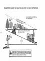
Mow up and down the face of slopes (not greater than 15°),
never across the face. Refer to page 55.
Red uce speed on slopes and make turns grad unity to prevent
tipping or toss of control. Exercise extreme caution when
changing direction on slopes.
While going up or down slopes, place gear shift control lever
in 1st gear position to negotiate the slope w_thout stopping.
Never mow in wet or slippery grass, when traction is unsure,
or at a speed which could cause a skid.
Stay alert for holes in the terrain and other hidden hazards.
Keep away from drop-offs ....
Do not drive too' close to creeks, ditches, and public highways.
Exercise special care when mowing around fixed objects in
order to prevent the blades from striking them. Never deliberately run tractor or mower into or over any foreign objects.
Never shift gears until tractor comes to a stop.
Never place hands or feet under the mower, in discharge
chute, or near any moving parts while tractor or mower ts
running. Always keep clear of discharge chute.
Use care when pulling loads or using heavy equipment.
a. Use only approved drawbar hitch poims.
b.
Limit loads to those you can safely control.
32.
33.
34.
35.
36.
37.
Use counterweight or wheel weights when suggested
owner s manual.
Watch out for traffic when crossing or near roadways.
When using any attachments, never direct discharge
material toward bystanders nor allow anyone near the v.
hicle while in operation.
Handle gasoline with care - it is highly flammable.
a. Use approved gasoline containers.
b. Never remove the fuel cap of the fuel tank or ac
gasoline to a running or hot engine or an engine that h_
not been altowed to coot for severat minutes after ru=
ning. Never fil! tank indoors. Atways clean up spi)i_
gasoline.: ......!_::'":_::i="_
::'-:,:
co Open do_r_:if the er_gtne iS run in,the garage - exhau:
fumes are d_ngerous D_ nQt run the engine ndoors,
Keep the vehicle and attachments in good operating cond
tion. and keep safety devices in place and working.
Keep all nuts, bolts, and screws tight to be sure the equi[.
ment is in safe working condition°
Never store the equipment with gasoline in the tank inside
buitding where fumes may reach an open flame or spar_
Allow the engine to cool before storing in any enclosure.
To reduce fire hazard, keep the engine free of grass, leave:
or excessive grease. Do not clean product while engine i
runntng.
Except for adjustments, DO NOToperate engine if airclean_;
or cover directly over carburetor air intake is removec
Removal of such part could create a fire hazard.
Do not operate without a muffler, or tamper with exhaut:
system. Damaged muff4ers or spark arresters could create,
fire hazard. Inspect periodically and replace if necessary.
The vehicle and attachments should be stopped and in
spected for damage after striking a foreign object, and th_
damage should be repaired before restarting and operatinc
the equipment.
Do not change the enginegovernor settings or overspeed th_
engine; severe damage or injury may result.
When using the vehicle with mower, proceed as fo]fows:
a. Mow only in daylight or in good artificial light.
b, Shut the engine off when unclogging chute,
c. Check the blade mounting bolts for proper tightness a
frequent intervals.
Do not operate the mower without the entire grass catcher
on mowers so equipped, or the deflector shield in place.
Disengage power to mower before backing up. Do not mo_
in reverse unless absolutely necessary and then only aftel
careful observation of the entire area 6ehind the mower,
38. Under normal usage the grass catcher bag material is subjec_
to deterioration and wear. ttshould be checked frequently fot
bag replacement Replacement bags should be checked tc
ensure compliance with the original manufacturer's recom
mendations or specifications.
2
CONGRATULATIONS
on your purchase of a Sears
Tractor. It has been designed, engineered and manufactured to give you the best possible dependability and
performance.
Should you experience any problem you
cannot easily remedy, please contact your nearest Sears
Service Department.
We have competent, well-trained
technicians and the proper tools to service or repair this
unit.
MAINTENANCE
RESPONSIBILITIES
NUMBER
DATE OF PURCHASE
THE SERIAL NUMBER
MODEL PLATE UNDER
AGREEMENT
A Sears Maintenance Agreement is available on this
product. See the nearest Sears store or service center
for details.
CUSTOMER
SERIAL
WILL BE FOUND ON THE
THE SEAT.
YOU SHOULD RECORD THESE NUMBERS
KEEP FOR FUTURE REFERENCE.
AND
........
Read and retain this manual
Study and observe the safety rules. Always use care when using your tractor. Always
keep your tractor and mower clean. Follow a regular schedule in maintaining, caring for, and using your tractor. A well
cared for tractor will run better and last longer.
A TTA CHMENTS
This unit can use many attachments now available at your Sears store. It can use a tiller, but cannot use other ground
engaging attachments such as a plow, harrow, or cultivator. See page 54 for a list of available attachments.
LmMiTED TWO YEAR WARRANTY
ON ELECTRIC START RIDING EQUIPMENT
For two years from date of purchase, when this tiding equipment is maintained, lubricated, and tuned up according
to ?,heoperating and maintenance instruction in the owner's manual, Sears wilt repair free of charge any defect in
material or workmanship in this electric start riding equipment.
This warranty excludes blade(s), blade adapter(s), spark plug(s), air cleaner and belt(s), which are expendable and
become worn during normal use.
This warranty does not cover:
o Tire replacement or repair caused by punctures from outside objects (such as nails, thorns, stumps, or
glass); and
• repairs necessary because of operator abuse or negligence, including the failure to maintain the equipment according to instructions contained in the owner's manual; and
- riding equipment used for commercial or rental purposes.
FULL 90 DAY WARRANTY ON BATTERY
For 90 days from the date of purchase, if any battery included with this riding equipment proves defective in material
or workmanship and our testing determines the battery will not hold a charge, Sears will replace the battery at no
charge.
WARRANTY SERVICE IS AVAILABLE BY CONTACTING THE NEAREST SEARS SERVICE CENTER DEPARTMENT IN THE UNITED STATES. This warranty applies only while this product is in use in the United States.
This warranty gives you specific legal rights, and you may also have other rights which may vary from state to state.
SEARS, ROEBUCK and CO., D/731CR-W, Sears Tower, Chicago, IL 60684
_DO
NOT OVERLOAD TRACTOR BY TOWING WEIGHTS GREATER THAN 150 POUNDS (68 KG).
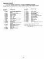
iNDEX
A
Adjustments:
Brake .....................................
Carburetor .............................
Clutch ....................................
Mower
Front-To-Rear ...................
Side-To-Side .....................
Throttle Control Cable ...........
Air Cleaner ...................................
16
21
25
23
23
21
18
Air Screen, Engine ....................... 19
Assembly .................................. 5-11
Attachments ................................. 54
B
Battery:
Charging ............................ 7, 2t
Cleaning ................................ 18
Installation ............................... 8
Levels .................................... 18
Preparation .............................. 7
Starting with Weak Battery .... 21
Storage .................................. 25
Terminals ............................... 18
Belt:
Motion Drive
Removal/Replacement
Mower Drive
..... 22
Removal/Replacement
..... 11
Blade:
Sharpening ............................ 17
Replace merit .......................... 24
Brake Adjustment ......................... 16
C
Carburetor Adjustment ................. 21
Clutch Adjustment ......................... 25
Controls, Tractor .......................... 12
Cutting Level, Mower .............. t 1,23
E
Engine:
Air Screen .............................. 19
Oil Change ............................. 18
Oil Level ................................. 16
Oil Type ................................. 16
Preparation ............................ 13
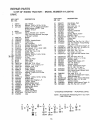
Repair Parts ...................... 46-51
Starting .................................. 13
Storage .................................. 25
F
Filter:
Air Cleaner ............................. 18
Fuel ........................................
19
Fuel:
Type .......................................
Storage ..................................
Fuse .............................................
H
Hood Removal/Installation
i3
25
22
........... 23
L
Leveling Mower Deck ................... 23
Lubrication:
Chart ...................................... 20
Tractor Pivot Points ............... 19
M
Maintenance ........................... 16-20
Air Cleaner ............................. 18
Foam Pre-cleaner ............. I8
Air Screen, Engine ................. 19
Battery ................................... 18
Blade Sharpening .................. 17
Brake Adjustment .................. t6
Engine Oil .............................. 16
Fuel Filter ............................... t9
Lubrication Chart ................... 20
Pump Fluid ............................. 17
Spark Plugs ........................... 19
Tire Care ........................ 8,17,25
Transmission .......................... t7
Mower:
Adjustment, Front-to-Rear ..... 23
Adjustment, Side-to-Side ....... 23
Blade Sharpening .................. 17
Blade Replacement ............... 24
Cutting Level ..................... t 1,23
Installation ............................. 10
Operation ............................... 14
Removal ................................ 23
Mowing Tips ................................. 15
Muffler .......................................... 19
Spark Arrester .................... 2,34
O
Oil:
Cold Weather Conditions ....... 16
Engine ................................... 16
Storage .................................. 25
Operation ................................ 12-15
Operating Your Mower .......... 14
Operating Your Tractor .......... 14
Starling the Engine ................ 13
Stopping Your Tractor ........... 13
4
Tractor Operation on Hills ...... 15
Options:
Attachments ........................... 54
Spark Arrester .................... 2,34
P
Parking Brake ............................... 12
Parts Bag .................................... 5-8
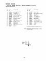
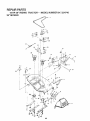
Parts, Replacement/Repair ..... 30-51
R
Repair and Adjustments .......... 20-26
Blade ...................................... 24
Carburetor ............................. 21
Fuse ....................................... 22
Hood Removal/installation ..... 23
Motion Drive Belt
Removal/Replacement ..... 22
Mower Drive Belt
Removal/Replacement ..... 11
Mower Adjustment
Front- to-Rear ................... 23
Side-to-Side ...................... 23
Mower Removal ..................... 23
Tire Care ................................ 25
Repair Parts ............................ 30-5t
S
Safety Rules ................................... 2
Seat ................................................ 7
Service Record ............................. 26
Slope Guide Sheet ....................... 55
Spark Plugs .................................. 19
Speed Control Chart .................... 14
Starting the Engine ....................... 13
Steering Wheel ............................... 8
Stopping the Tractor ..................... t3
Storage ......................................... 25
T
Throttle Control Cable
Adjustment ............................. 21
Tires ..............................................
8,17,25
Trouble Shooting Chart ........... 27-28
Transaxle:
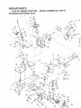
Repair Parts ...................... 42-45
Transporting ................................. 14
W
Warranty ......................................... 3
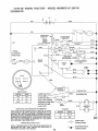
Wiring Schematic ......................... 29
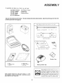
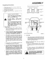
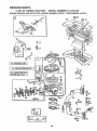
ASSEMBLY
To assemble
and adjust
(2)
(1)
(1)
(1)
(1)
(2)
your
7/16" wrenches
9/16" wrench
1/2" wrench
3/4" wrench
3/4"'socket
! 1/16" Wrenches
tractor
you
will need:
Tire Pressure Gauge
Screwdriver
Utility Knife
Ratchet Wrench
Take all of the items out of the box. The box contains the items shown below,
contents (see below and page 6).
Parts
Bag
Battery
Open the parts bag and check the
Contents
Carrfage
Not
Bolt
Shown
. I 4
Full
- 20
x
S_ze:
7-
! 2
d
C.
Terminal
15 _ Slope
Instruction
Guard
Sheet
(2) Keys
b
Battery
a.
b,
c.
seat
steering
battery
wheel
d. battery
acid
e. owner's
manual
f. parts bag
NOTE: RIGHT HAND (R.H,) AND LEFT HAND (L,H.) ARE
DETERMINED
FROM OPERATOR'S
POSITION
WHILE
SEATED ON THE TRACTOR,
Steering
Wheel
Caps
Cap
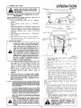
The operation
of any tractor can result tn
foreign objects thrown
into the eyes, which
can result
in severe eye damage.
Always
wear safety glasses or eye shields before
starting your tractor and while mowing,
We
recommend
Wide Vision Safety Mask worn
over spectacles
or standard
safety glasses,
available at Sears Retail or Catalog Stores,
A
Y
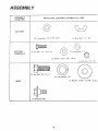
A SSEMBL Y
L OCA TION
PARTS
BAG
CONTENTS
SHOWN
FULL
SIZE
BA TTER Y
(2) Lockwasher,
BA TTER Y
TERMINA
LS
(2) Hex Bolt,
!/4
t/4
_ 20x
IntiExt
Tooth
(2) Wing
Nut
(2) Lockwasher
3/4
(2) Washer
9/32
x 5/8 x
_ I/4
- 20
1/4
t6 Ga,
©
(2) Hex Nut,
(1) Hex Bolt,
1/2-
13 x 1
(1) Lockwasher,
1/2
(1) Washer, 17/32x
SEAT
(1) Shoulder
Bolt
1/4 - 20
1,3/16x
12 Ga.
ASSEMBL Y
Unpacking
1,
2.
3,
4.
instructions
Take items out of box;
the box contains
the
items shown below.
Cut down four corners of the carton with a utility
knife and fold down sides,
Disengage Parking Brake.
Carefully
guide
the tractor
backwards
off
the
skid,
WEAR
EYE AND FACE
VENT
TUBE
BATTERY
BATTERY
CELL
SHIELD,
WASH HANDS OR CLOTHING IMMEDI*
ATELY
IF ACCIDENTALLY
IN CONTACT WITH BATTERY
ACID,
DO NOT
CHARGED
PLOSIVE.
SMOKE.
BATTERY
FIGURE
FUMES
FROM
ACID ARE EX-
SEAT
READ THE INSTRUCTIONS
INCLUDED
WITH
THE
BATTERY
VENT
CAPS
FOUND tN THE BAG OF PARTS.
ALWAYS
WEAR
GLOVES,
CLOTHING
AND GOGGLES
TO PROTECT
YOUR
HANDS, SKIN AND EYES.
PAN,,
b,
C.
d_
e.
1
SEAT
SHOULDER
BOLT
EN"
_LT
FUEL
TANK
CAP
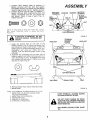
Prepare Battery
a. Fill and charge
battery
(be/ore
insta/fingt,
NOTE: SEE DETAILED INSTRUCTIONS
PACKAGED WfTH THE BATTERY VENT CAPS FOUND
IN THE BAG OF PARTS.
T.
CAP
Fill each cell with battery acid. Add the acid until it
reaches the bottom of the battery vent tubes (Fig,
1), NOTE: DO NOT OVERFILL. OVERFILLING
WILL RESUL T IN DAMAGE TO TRACTOR.
1
CLUTCH/BRAKE
PEDAL
FIGURE
Allow battery to stand and settle for at least thirty minutes.
If the level of acid falls below the
point described
in step (b), add more acid until
the correct
level is reached.
NOTE: UNEVEN
FILLING OF CELLS WILL AFFECT THE BATTERY
CAPACITY
AND LIFE. Install the battery caps to
cover the vent wells. Wash the top of the battery with water to remove any acid, then wipe
dry.
2,
Install
a_
2
Seat
Place seat on seat pan. Screw adjustment bolt, lockwasher and flat washer into seat (Fig. 2). Screw shoulder
bolt into seat, Bolts, [ockwasher, and flat washer found in
bag of parts. Tighten shoulder bolt securely using a 1/2"
wrench. Tighten adjustment bolt.
NOTE:THE SHOULDER BOLT WiLL BE LOOSE IN
THE SEAT PAN SLOT.
b. P/ace seat in operating position, Sit on the seat
and press c/utch/brake pedal a// the way down.
If operating position is not comfortable,
adjust
seat.
Check battery case for leakage to make sure that
no damage has occurred
in handling.
It is recommended that the battery be charged
before use. Use a 12 volt battery charger. Charge
battery at a rate of 6 amperes for 1 hour.
NOTE:OBSERVE ALL SAFETY' PRECAUTIONS
REQUIRED FOR BATTERY CHARGING. Check
the acid level after the battery is charged, ff the acid
has fallen below the correct level, add water.
c, To adjust, raise seat, Loosen adjustment
bolt
(Fig, 2) and slide seat to a comfortable
operating position. Tighten ad/ustment bo/t secure/y
using a 3/4"" wrench.
Neutralize excess battery acid for disposal by
adding it to 2 gallons (7.5 litres) of water in a 5
gallon (20 fitres) plastic container.
Stir with a
wooden or plastic paddle while adding baking soda
until the addition of more soda causes no more
foaming.
ADJUSTMENT BOLT, LOCKWASHER,
AND FLAT WASHER MUST BE TiGHTENED SECURELY TO PREVENT MOVEMENT OF THE SEAT.
7
ASSEMBL Y
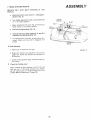
3.
tnstafl Steering
Wheel
NOTE: POSITION FRONT WHEEL FORWARD.
a. Use a 3/4"
wrench
to remove
hex lock nut,
and
2 - 1/4" diameter washer (shown full size
below) from steering column (Fig. 3)
STEERING
.........
HEX
2 . t/4"
__'_
.___t'_
WHEEL
CAP
LOCKNUT
DIA,
_"_'STS
WASHER
T E E R t N O WHEEL
b.
Position steering wheel over steering wheel insert.
c.
Secure steering wheel to steering column using
the 2-1/4" diameter washer and the hex lock nut
(Fig. 3). Torque to 50 ft. Ibs. (67. 79 N-m).
d.
:IGURE
3
&
Snap steering wheel cap in place on steering
wheel Steering wheel cap found in bag of parts.
Check Tires
Reduce tire pressure to 14 PSI (1 kg per cn'F) in front
tires and 12 PSI (0.84 kg per crfP) (Tires were oven'nflated for shipping purposes).
AIR
HOOD
INTAKE
DUCT
5.
Install
Battery
DO NOT
NALS.
SHORT
BATTERY
TERMI-
BEFORE
INSTALLING
BATTERY,
REMOVE METAL BRACELETS, WRIST=
WATCH BANDS, RINGS, ETC,
\
Lift hood from rear sides (Fig. 4).
b.
Make sure drain tube (Fig. 6) is fastened to drain
hole in battery tray and battery tray is positioned in
hole of battery support.
c.
Place battery in plastic tray (battery terminals to
front of tractor)(Fig. 6).
\
GRILL
BATTE R Y
COMPARTMENT
_IGURE
a.
4
POSITIVE
TERMINAL
MUST 8E CONNEC- l
TED FIRST TO PREVENT SPARKS FROM
ACCIDENTAL
8
GROUNDING.
==J
ASSEMBL
d. Connect RED battery cable to positive
(+)
battery
terminal
with hex bolt, flat washer,
lockwasher and hex nut (shown full size below)
found in bag of parts (Fig. 5). Tighten securely.
e. Connect BLACK ground cable to negative (-)
battery terminal with remaining hex bolt, flat
washer, Iockwasher and hex nut (shown full
size below) found in bag of parts (Fig. 5).
Tighten securely.
BATTERY
TERMINAL
RED
WASHER
WASHER
Y
BATTERY
TERMINAL
BOLTS
BLACK
4AEGITIVE)
8LE
\
NUT
NUT,
NOTE:
tF YOU HAVE
A WEAK
ING
YOUR
TRACTOR
WITH
(PAGE 21 ).
BATTERY,
SEE "STARTA WEAK
BATTERY"
LOCKWASHERS
FIGURE
iF BATTERY IS REMOVED, DO NOT
OPERATE ENGINE. SPARKING MAY
OCCUR.
WING NUT
TERMINAL
ACCESS
DOORS
KEY HOLE
,DRAINTUBE
5
WING NUT
f. Using the slotted hole on one side of the
battery support (Fig. 6) insert one battery bolt
into frame slot (head of bott down). Fasten the
battery bolt to the terminat guard using int./ext.
!ockwasher
and wing nut. (Bolts and !ockwashers, nuts and terminal guard found in bag
of parts).
g. Assemble the remaining bolt to other side of
battery support and fasten terminal guard to it
with remaining int./ext,
tockwasher and wing
nut (shown fu!l size below). Tighten wing nuts
securely by hand (Fig. 6).
h. Remove plastic
;: Secure hood.
NOTE:
USE TERMINAL
from
TRAY
tractor hood and close.
FIGURE
ACCESS
DOORS
(FIG.
6) FOR:
1,
INSPECTION
FOR SECURE
CONNECTIONS
(TIGHTEN
HARDWARE)
2. INSPECTION
FOR CORROSION
3. TESTING
BATTERY
4. JUMPING
(IF REQUIRED)
5. CHARGING
(IF REQUIRED)
KEEP TERMINAL
ACCESS DOORS
CLOSED WHEN NOT IN USE.
DO NOT START ENGINE OR DRIVE
TRACTOR UNTIL MOWER HAS BEEN
iNSTALLED, OR PARALLEL LINK HAS
BEEN REMOVED.
SEE MOWER INSTALLATION
lo).
9
(PAGE
6
ASSEMBL
Y
Mower Installation
Your 38"mower
installs without
the use of tools.
a. Raise lift lever (Fig. 9) to its highest position.
.
\\
"x
b.
Turn height adjustment
knob counterclockwise
(f_'J
to lowest position
(Fig. 9).
C.
Install front hinge pin through
tractor axle ano
paraltel fink (Fig. 7), Secure with retainer spring.
NOTE:
SMALLER
END OF PARALLEL
LINK
MOUNTS TO TRACTOR,
d.
Install rear hinge pin through mower lift brackets
and parallel link (Fig, 7), Secure with retainer
spring,
RETAINER
\\
PARALLEL
_
SPRINGS
-
LEt
FRONT
_I
_
Move
arms.
lever
forward
to
lower
suspensior
REAR
Slide trunnions through lift bracket holes an_
secure with retainer spring (Fig. 8).
f+
PiN
FIGURE
lift
7
With belt routed around R.H. mower pufle'_
and idler put/ey,
ro//
belt
over enginc
pulley
(Fig. 8) Drive schematic decal or
mower housing.
g,
\
h.
Roll
belt
i.
Use lift
over
lever
L.H. mower
pu//ey.
to raise mower.
Turn height
adjustment
knob
(,F-, ) to the middle of its travel.
j*
ctockwis_
ENGINE
PULLEY
LIFT LEVER
"HIGHEST"
FIGURE
POSITION
LIFT' LEVER
"LOWEST"
POSITION
8
ATTACHMENT
CLUTCH
HEIGHT
KNOB
'ADJUSTMEN_I
FIGURE
10
9
A SSEMBL
REPLACE
MANUAL.
ONLY
W_TH
BELTS
SPECIFIED
a,
Place attachment
clutch
position
(Fig. 9),
b.
Turn height adjustment
knob
(_-")
to lowest
position,
c,
d.
8.
f .
Move
lower
switch
IN
Y
THIS
in "disengaged"
counterclockwise
ENGtNE
IDLER
attachment
lift lever (Fig, 9) forward
mower
to its lowest position,
BELT
to
LH.
MANDREL
Rofl belt off engine pufley (Fig. 10).
Remove belt from mower pulleys (L.H. and R.H.
mandrels) and idler pulley (Fig. 10).
To install mower
drive belt, reverse above procedure, Make sure drive belt is engaged in all
pulleys.
SPRING
8. Final Assembly
a, Make
sure
all fasteners
are tight,
FIGURE
b. Read and follow the operation instructions
(page 12). Know the location and purpose of
a// controls.
c . Check oil and gasoline
the tractor.
9,
Check
the Cutting
(page
73) before
starting
Level
A fter mowing
a short distance,
look at the area
that was cut. If the blade housing
cuts uneven,
see the instructions
on "'Side-to-Side
and Frontto-Rear Mower A'djustment'"
(page 23),
11
10
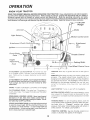
OPERA TION
KNOW
YOUR
TRACTOR
READ THIS OWNER'S MANUAL BEFORE OPERATING YOUR TRACTOR. If you understand the unit and its operation,
you will achieve efficient and peak performance,
While reading the manual, compare the illustrations with your tractor to
familiarize yourself with the location of various controls and adjustments, Study the operating instructions and safety
precautions thoroughly to insure proper functioning of your tractor and to prevent injury to yourself and others. Be sure to pay
strict attention to all warnings and cautions: they are included for your safety. Save this manual for future reference.
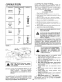
Lift Lever
Plunger
Choke
Motion
Control
Lever
_ttle Control
Height
Adjustment
i
Knob
i Pork,ng
ro.o
Free-Wheel
IGNITION:
start.
ATTACHMENT
CLUTCH SWITCH;
Pull switch out and
up to engage mower.
Operator
must be positioned
in
seat. There will be an engine hesitation
as the clutch
engages.
AMMETER:
ammeter.
To start
a cold engine,
pull choke
and turn
Leve_
to the right
to
Each time you start your tractor, check you_°
The needle should move towards
the (+)
charging mark indicating
the battery is being charged as
you operate the tractor,
The headlights
will not show a
discharge
on the ammeter
because they are not corn
nected
to the battery
(they have their own efectrieaI
source),
A TTA CHMENTLIFTLEVER:
Use the attachmenttift lever
to raise and lower the attachment mounted toyour tractor.
Push plunger and move the lift lever forward to lower
attachment,
CHOKE:
Place key in ignition
Control
out to engage.
LIGHT
CLUTCH/BRAKE
PEDAL: The pedal has 2 functions:,
a
clutch and a brake. To engage the brake push the pedal
completely.
SWITCH:
Turns
on and off
the headlights.
MOTION CONTROL LEVER: From neutral position,
move
lever upward for forward motion or downward
for rear.
ward motion, Increased movement
produces an increase
in speed.
FREe.WHEEL CONTROL LEVER: Move lever forward
and !ock in "J" s!ot, then move motion control lever to
neutrat position when pushing ertowing the tractor. Do not
tow faster than 3 MPH (4,8 Kmh).
PARKING BRAKE: To set the parking brake, push the
clutch/brake
pedal completely
forward.
Place the parking brake lever in "Engaged"
position
and release
pressure
from pedal. C/utch/brake
pedal will remain in
brake position,
To release, push pedal in.
HEIGHTADJUSTMENT
KNOB: Use the height adjustment knob
to adjust the mower height. With the attachment lift lever in the
"up" position, turn knob clockwise oo-to raise cutting height and
counterclockwise--to lower cutting height. Lower Attachment lift
lever to lower attachment to selected height.
THROTTLE
CONTROL:
Use the throttle
control
crease or decrease
the speed of the engine.
12
to in-
,!
1. StOpping
Your
OPERA TION
Tractor
./
-
CAUTION:DO
NOT CHOKE CARBURETOR
TO STOP
THE ENGINE,
NOTE: REMOVE KEY WHEN LEAVING TRACTOR
TO
PREVENT UNAUTHORIZED
USE.
a. Push clutch!brake
pedal
into
full "BRAKE"
position.
b Move
motion
control
lever
to "'NEUTRAL"
position.
c
Place parking brake in "'ENGAGED"
position and
release pressure from clutch/brake.
Pedal should
remain in "'BRAKE"position.
NOTE: MAKE SURE
PARKING
BRAKE
WiLL
HOLD
TRACTOR
SECURE.
d. Place attachment
clutch switch in "DISENGAGED" position.
e. Move throttle
control to "'S" (stow) position.
f. Turn ignition key to "OFF" position.
Never use
choke to stop engine.
2. Starting
The Engine
LEARN TO START, STOP AND REVERSE
YOUR TRACTOR iN A LARGE, OPEN AREA.
THiS TRACTOR
iS EQUIPPED WiTH INTERLOCK SWITCHES TO PREVENT STARTING OF THE TRACTOR
ENGINE WHILE
THE ATTACHMENT
CLUTCH SWITCH iS iN
THE "ENGAGED"
POSITION AND/OR THE
FOOT PEDAL IS NOT FULLY DEPRESSED. /
IMMEDIATELY
REPLACE SWITCHES THAT
ARE NOT IN PROPER WORKING
ORDER.
DO NOT ATTEMPT TO DEFEAT THE PURPOSE OF THESE SWITCHES.
SEAT
b.
CAUTION',
:UEL
TANK
CAP
.!
CLUTCH
This engine has been shipped
filled with summer weight oil. For cold weather operation,
see
chart on page 16. Check engine oil level with
tractor
on level ground,
Remove
and wipe
dipstick
(Fig.
11) clean, push it in tight for a
few seconds,
remove
and read oil level.
If
necessary,
add
oil until
"FULL"
mark
is
reached,
Fill fuel tank (Fig. 12). Use fresh, clean, regular
UNLEADED
automotive
gasoline (Use of leaded
gasoline will increase carbon and lead oxide deposits and reduce valve life). Capacity is 3-1/2
gallons (13.24 litres).
EXPERIENCE
INDICATES
THAT ALCOHOL SLENDED FUELS
|CALLED GASOHOL
OR USING ETHANOL OR METHANOL)
CAN ATTRACT
MOISTURE
WHICH LEADS TO SEPARATION
AND FORMATION
OF ACIDS DURING
STORAGE,
ACIDIC
GAS CAN DAMAGE
THE FUEL SYSTEM
OF AN ENGINE
WHILE IN STORAGE,
TO
AVOID
ENGINE
PROBLEMS,
THE
FUEL
SYSTEM
SHOULD
BE EMPTIED
BEFORE
STORAGE
FOR 30 DAYS
OR LONGER.
DRAIN
THE GAS
TANK,
START
THE ENGINE
AND LET IT RUN UNTILTHE
FUEL LINES
AND
CARSURETOR
ARE EMPTY,
USE
FRESH
FUEL NEXT
SEASON.
SEE STORAGE INSTRUCTIONS
FOR ADDITIONAL
iNFORMATION,
NEVER USE ENGINE
DUCTS
IN THE FUEl
MAY OCCUR,
_ISEAT
SHOULDER.
BOLT
J
a,
AIR iNTAKE
_ DUCT
BRAKE
FiLL TO BOTTOM OF GAS TANK FILLER
NECK, DO NOT OVERFILL. WiPE OFF ANY
SPILLED OIL OR FUEL. DO NOT STORE,
SPILL OR USE GASOLINE NEAR AN OPEN
FLAME.
r x
/ ......._
FIGURE 12
switch in "DISENGAGED"
c,
Place attachment
clutch
position
(Fig, 15),
d, Push clutchtbrake
pedal
fully into brake position
(Fig. 14),
e. Place motion control lever in "NEUTRAL"
position
(Fig. 15).
f. Move throttle control lever (Fig, I5)
past "FAST"
to the "CHOKE"
position
g.
Turn ignition key' clockwise
(,f'_)
to "START'*
position and release key as soon as engine starts.
NOTE: DO NOT RUN STARTER CONTINUOUSLY
FOR MORE
THAN
FIFTEEN
SECONDS
PER
MINUTE. tf engine does not start after several attempts,
move
throttle
control
to "F'" (fast)
position,
wait a few minutes
and try again.
NOTE: IF YOU HAVE A WEAK BATTERY,
SEE "STARTING YOUR TRACTOR
WITH
A WEAK
BATTERY"
(PAGE 21 ).
h, After engine starts move throttle control lever slowly'
to the "SLOW"
position.
The first time you start
the engine, it wi!t take extra cranking time to move
fuel from tank to the engine,
NOTE:
ALLOW ENGINE TO WARM UP FOR A FEW MINUTES
BEFORE ENGAGING
CLUTCH OF TRACTOR OR ATTACHMENT,
i,.
OR CARBURETOR
CLEANER
PRO+
TANK
OR PERMANENT
DAMAGE
PEDAL
When restarting
a warm
control
midway between
"F'" (fast) position.
engine, move throttle
slow "S'" (slow) and
IMPORTANT: BEFORE DRIVING THE
TRACTOR,
INSTALL
MOWER OR
REMOVE MOWER PARALLEL LiNK
(SEE FIGURE 7).
13
OPERA TION
FUNCTtON
MOTION CONTROL
3. Operating
Your Tractor _nd Mower
NOTE:
THIS
TRACTOR
IS EQUIPPED
WITH
AN
OPERATOR
PRESENCE SENSING SWITCH.
ANY ATTEMPT BY THE OPERATOR TO LEAVE THE SEAT WITH
THE ENGINE
RUNNING
AND
THE ATTACHMENT
CLUTCH ENGAGED WILL SHUT OFF THE ENGINE.
THROTTLE
8,co
CAUTION
Normat
Mowing
TO AVOtD
tNJURY
1. Read owner's
manual•
2. Know the location
and function
of all controls.
3.
Keep guards, safety shields and switches
in place
and working.
4. Remove objects that can be thrown
by blades.
5. Do not mow when children and others are around,
6, Never carry children or passengers•
7. Always
look behind machine before backing,
8, Do not mow where machine can tip or slip.
9. tf machine stops going uphill, stop blade and back
slowly down>
10. Be sure blades and engine have stopped before placing hands or feet near the blades.
I. Remove key when leaving machine.
Heavy
Mowing
Snow
Blower
and
FAST
Tilling
MAKE SURE PARKING
TRACTOR SECURE.
Snow
Blade
NEVER PLACE YOUR HANDS OR FEET iN
OR UNDER ANY POWERED ATTACHMENT
OR NEAR ANY
MOVING
PART WHILE
TRACTOR
OR ANY POWERED ATTACHMENT IS RUNNING,
7
Transport
NOTE: ALWAYS OPERATE ENGINE AT FULLTHRO-rTLE
WHEN MOWING TO ASSURE BETTER MOWING PERFORMANCE, AND PROPER DISCHARGE QF CUT
MATERIAL. REGULATE GROUND SPEED BY SELECT _
ING A LOW ENOUGH SPEED (FIG. 13) TO GIVE THE
MOWER CUTTING PERFORMANCE PLUS QUALITY OF
CUT DESIRED.
SLOW-FAST
FIGURE
BRAKE WILL HOLD
13
DO NOT OPERATE THE MOWER WITHOUT EITHER THE ENTIRE GRASS
CATCHER,
ON
MOWERS
SO
EQUIPPED,
OR THE DEFLECTOR
SHIELD IN PLACE.
\
FIGURE
!4
TION"
READ
YOUR
CAUTION:
CAREFULLY
THE
"RULES
MOWER.
BEFORE
OPERATING
FOR SAFE
OPERA-
DO NOT ADD ADDITIONAL
WEIGHT TO THE
TRACTOR
OTHER
THAN
THE OPTIONAL
WHEEL
WEIGHTS.
EXCESSIVE
WEIGHT
MAY OVERLOAD AND DAMAGE THE TRANSMISSION.
THE MOWER MUST BE ADJUSTED
PROPERLY FROM
FRONT TO REAR AND LEVELED FROM SIDE TO SIDE
BEFORE OPERATING. THIS IS NECESSARY FOR LEVEL
AND EFFICIENT MOWING, REFER TO PAGE 23.
14
a. Select desired height of cut position
using
height adjustment knob (Fig. 15).
b. Raise rift lever and place attachment
clutch
switch in "disengaged'position.
c. Push clutch/brake
pedal down firmly (Fig. 14).
d. Start engine (page 13).
e. With engine running and warm, place throttle
control midway between "S'" (slow) and "F'"
(fast) positions.
f. Engage mower
with the attachment
clutch
switch.
g. Move motion control
lever to desired speed
and direction.
h. Lower
mower
into
cutting
position
using
attachment rift lever.
i. Release clutch/brake
pedal to start movement
(Fig. 14).
j. Move throttle control to ,;c,, (fast) position.
NOTE: SELECT A GROUND SPEED THAT WILL SUIT
THE TERRAIN, QUALITY OF CUT AND ATTACHMENT
BEING USED. (See Fig. 13),
TION
CAUTION:NEVERRUN
THE ENGINE WITHOUT AIR
iNTAKE DUCT INSTALLED (FIGURE 11),
4.
Mowing
NOTE:
MOWER
Tips
TIRE
CHAINS
CANNOT
HOUSING
ATTACHED.
BE
USED
WITH
THE
i
READ
THE "SAFETY
RULES"
CAREFULLY
BEFORE
OPERATING
YOUR
MOWER.
REFER TO PAGE 2,
a.
]
i
Use the runner on the R.H. side as a guide; the
blade cuts approximately an inch (2.54 cm) outside
the runner (Fig. 16).
b. Drive so that clippings are discharged onto the
area that has been cut. Have the cut area to the
right of the machine. This will result in a more
even distribution
of clippings and more uniform
cutting.
FREE.WHEEL
CONTROL
KNOB
c. When mowing lar_le areas (Fig. 17), start by
turning to the right so that the clippings witl
discharge away from shrubs, fences, driveways,
etc. After
one or two rounds, mow in the
opposite
direction
making
left hand turns
und/ finished.
\,
FIGURE
t5
d. If (irass is extremely
tall, it should be mowed
twice. The first time cut relatively high," the
second time to the desired height.
e. The left hand side of mower shoutd be used for
trimming.
f. Do not mow tall dry (brown) grass over 6" (15.24
cm), as this may be a fire hazard.
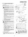
5. Operating The Tractor On Hills
R,H
RUNNER
DISCHARGE
GUARD
DO NOT DRIVE
UP OR DOWN
HILLS WITH
SLOPES
GREATER
THAN
15 ° AND DO NOT
DRIVE
ACROSS
ANY
SLOPE.
REFER
TO
PAGE 55.
a. Choose the slowest speed BEFORE
or down hills.
b. AVOID
STOPPING
ON HILLS.
C_
OR CHANGING
FIGURE
17
K
1
SPEED
If slowing is necessary, move motion control
lever towards "N'" (neutral) position or throttle
control lever to middle position.
t;
After starting your tractor, disengage parking
brake and release clutch/brake pedal St OWL Y.
To start tractor forward, move motion control
lever forward to desired speed.
i
f. Make aft turns graduafly.
,
16
starting up
d. if stopping
is absolutely
necessary, push
clutch/brake
pedal quickly to "brake"position
and engage parking brake.
e.
FIGURE
Flip-Up Discharge Guard
Your mower has a flip-up discharge guard (Fig. 16)
for door or gate clearance when held in raised
position.
15
MAKE
SURE
ATTACHMENT
CLUTCH
SWITCH
IS tN "DISENGAGED'"POSITtON
AND
BLADES
HAVE
STOPPED
BEFORE
RAISING
DISCHARGE
GUARD
(DEFLECTOR). NEVER
OPERATE
MOWER WITHOUT
1
DISCHARGE
POSITION.
I
GUARD
IN
OPERATING
INTENANCE
First 2 Hours
AIR SCREEN
(Two
Mowings)
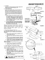
1. Change Engine Oil
Changing oil after the first two hours (or two mow _
ings) will help eliminate break-in residue which might
be damaging to your engine.
OIL FILLER
CAP!DIPSTICK
NOTE: BE CAREFULL NOT TO ALLOW DIRTTO ENTER
THE ENGINE WHEN CHANGING OIL.
a.
Drain oil with engine warm,
b.
c.
Loosen oil drain ptug and remove dipstick (Fig. 18).
Catch oil in a suitable container.
d.
Tighten oi! drain plug.
e.
Refill engine oil (Fig, 19). Refill capacity is 1-1/2
quarts (1.42 litres). NOTE: DO NOT OVERFILL.
L
OiL DRAIN
FIGURE 18
Replace dipstick.
Dipstick assembf_, must be
securely tightened into tube at all times when
engine is operating.
Recommended SAE Viscosity Grades
/
Determine temperature range expected before next oil
change. All oil must meet A. P.I. service classification SD,
SE or SF.
.20 °
0°
FIGURE 19
32 °
60 °
80 °
CAUTION:
TO AVOID DAMAGE TO THE STARTING
SYSTEM, USE SAE 5W30 OIL WHEN THE
TEMPERATURE FALLS BELOW 32 ° F (0 ° C).
NOTE: FRESH, CLEAN WINTER GRADE FUEL MUST
BE USED TO INSURE GOOD COLD WEATHER STARTING.
100 °
To keep
your
tractor
running
better,
longer, perform
necessary
service
using
the following
maintenance
schedule:
Every
BEFORE MAKING ANY INSPECTION,
ADJUSTMENT
OR REPAIR:
1.
MOVE MOTION CONTROL
N=.UTRAL POSITION.
3.
PLACE
PARKING
GAGED"
POSITION.
FROM PEDAL.
PLACE
SWITCH
TION.
CLUTCH
POSI-
6.
MAKE
ABSOLUTELY
SURE
THE
BLADES
AND ALL MOVING
PARTS
HAVE COMPLETELY
STOPPED.
8.
NOTE:
DO NOT
Every
25 Hours
1.
TURN
TION.
IGNITION
REMOVE
Several minutes after stopping engine, check engine
oil level with tractor on level ground. Wipe dipstick
(Fig. 18) clean, push it down tight for a few seconds,
remove and read oil level
If necessary, add oil
until "FULL" mark is reached (See Figure 19).
BRAKE
IN "ENREMOVE FOOT
5.
7_
WITH ENGINE RUNNING.
LEVER TO
ATTACHMENT
IN "DISENGAGED"
KEY TO "OFF"
THE IGNITION
POSI-
OVERFILL,
(Twice
a Mowing
Season)
CHECK BRAKE OPERA T/ON
This tractor is equipped with an adjustable disc
brake,Mountedon the right side of the transax/e(fig.21).
IF TRACTOR REQUIRES MORE THAN
SIX FEET (1.83 M) STOPPING DISTANCE IN HIGHEST GEAR, THEN
BRAKE MUST BE ADJUSTED.
KEY.
DISCONNECT
THE
SPARK
PLUG
WIRE FROM THE SPARK PLUG AND
KEEP WIRE AWAY FROM THE SPARK
PLUG TO PREVENT
INJURY
FROM
ACCIDENTAL
STARTING.
BE CAREFUL TO AVOID TOUCHING
HOT ENGINE OR MUFFLER COMPONENTS.
NOTE: A 1/2" WRENCH AND A RULER ARE REQUIRED TO ADJUST BRAKE.
a.
b,
C.
With Every Mowing
1. Make sure all nuts on bolts are tight and cotter
pins and retainer springs are secure.
2. Observe all safety precautions.
3. Keep tractor well lubricated (refer to page 19 ).
(Five Mowings)
Check Engine Oil Level
PUSH
TRACTOR
CLUTCH/BRAKE
PEDAL
COMPLETELY
INTO BRAKE
POSITION,
2.
4.
I,
5 Hours
16
Depress Clutch / Brake Pedal and engage Parking
Brake.
Measure distance between brake operating arm and
nut "A" on brake rod.
ff distance is other than 1-1/2" (3.8t cm), loosen
jam nut (Fig. 21) and turn nut "A" until distance
becomes 1-1/2" (3.81 cm), Retighten jam nut
against nut "A"
Road test tractor for proper stopping distance as stated
above. Readjust if necessary.
INTENANCE
2.
Tire Cam
l
Maintain tire pressure in front at 14 PSI (1 kg per crr£)
and in rear at 12 PSI (0.84 kg per crrP).
3.
CENTER
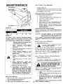
Blade Sharpening
For best results, Mower blades must be kept sharp. The
blades can be sharpened with afew strokes of a fife or on
a grinding wheel We suggest they be sharpened after
every 25 hours of mowing. Do not attempt to sharpen while
on mower, ff you mow in sandy soil check the blades after
each two mowings. The sand may wear the blades away
rapidly.
a. When grinding, care should be taken to maintain blade balance and the blade should be
checked for proper balance be fore reinstallation
on mower.
Unbalanced or bent blade will
cause excessive vibration
when running, and
eventual damage to mower or engine. Replace
bent or damaged blades.
b.
FIGURE 20
WITH PARKING
RAKE ENGAGED)
NUT "A"
JAM NUT
BRAKE ROD
DISC BRAKE,_
BRAKE OPERATING ARM
To check blade balance, drive a nail into a beam or
wall. Leave about one inch (2.54 cm) of the straight
nail exposed. Place center hole of clean blade
over the head of the nail (Fig. 20).
NOTE:
CENTER
HOLE
OF BLADE
ON NAIL.
IF BLADE
IS
PROPERLY
BALANCED,
BLADE
SHOULD
REMAIN
IN
POSITION
SHOWN
IN FIG, 20, IF EITHER
END OF THE
BLADE
MOVES
DOWNWARD,
BLADE
IS NOT
BALANCED,
SHARPEN
THE
HEAVY
END
UNTIL
BLADE
iS BALANCED.
4.
t
Check
Pump
Assembly
Fluid
_GURE21
FASTENERS
Level
NOTE: BEFORE CHECKING
OIL LEVEL, CLEAN RESERVOIR
AND CAP WITH CLOTH TO REMOVE
DUST OR GRASS
CLIPPINGS.
TILLER
INTERLOCK
LOOP
a.
b.
c.
d.
Using a 9/16" wrench remove 4 fasteners to remove Drawbar (Fig. 22).
Disconnect Tiller Attachment Interlock Loop (Fig.
22).
FASTENERS
Check for proper fluid level in reservoir. Fluid level
should be above the "Oil Level Cold, line(Fig. 23).
DRAwBAR
Remove cap..on reservoir, and bladder (Fig. 23)
and fill to Oil Level Cold line with SAE 10W30.
NOTE: RESERVO1R CAP IS REMOVED WITH ACLOCKWISE ROTATION.
e.
Replace Cap until snug (Do not overtighten).
f.
Reconnect Tiller Attachment Interlock Loop.
5. Check Hydrostatic Transmission Cooling
DO NOT ATTEMPT TO CLEAN FAN OR TRANSMISSION
WHILE
ENGINE
IS
RUNNING
OR WHILE
THE
HYDRO-
HOT.
a. Inspect cooling fan (Fig. 23) to assure fan
blades are intact and clean.
b. Inspect hydrostatic
cooling fins (Fig. 23) for
dirt, grass clippings and other material
that
could hinder fan air from properly
cooling
transmission.
c. Thoroughly clean the cooling fins with a cloth,
brush or compressed air.
STATIC
TRANSMiSSiON
IS
COOLH_G
tNG
FiNS
WEAR SAFETY GLASSES WHEN USING
COMPRESSED AIR
!7
FIGURE 23
INTENANCE
_
CUT
AWAY
VENT
b.
c.
d.
CAP
VIEW
e.
2,
TUBE
Keep battery and terminals
clean.
Keep battery bolts tight.
Keep vent caps tight and small vent holes in caps
open,
Recharge at 6 amperes for 1 hour if necessary,
Clean
Battery
and Terminals
Corrosion and dirt on the battery
battery to "leak"
power.
BATTERY
CELL
BATTERY
LEAD-ACID
FIGURE
24
PLOSIVE
and terminals
BATTERIES
GASES.
KEEP
cause the
GENERATE
SPARKS,
EXFLAME
AND SMOKING
MATERIALS
AWAY
FROM
BATTERIES.
ALWAYS
SHIELD
YOUR EYES
AROUND
CARTRIDGE
PLATE
Spitback
Shield
R I ES.
a.
Remove terminal guard.
b.
Disconnect BLACK battery cable then RED battery cable and remove battery from tractor.
c,
Wash battery with4 tablespoons (60 grams) of
baking soda to I gallon (3.8 litres) of water.
NOTE: BE CAREFULL NOT TO GETTHE
TION INTO THE BATTERY CELLS.
_.
Rinse the battery with plain water, dry and reinstall
in tractor.
e.
Clean terminals and battery cable ends with wire
brush until bright,
L
Replace battery cables, connecting RED battery
cable to positive terminal first, then BLACK battery
cable to negative termfnaL Coat terminaf connections with petroleum jelly.
g.
Replace terminal guard.
FOAM
PRE CLEANER
3.
SODA SOLU-
d.
PAPER
CARTRIDG_
BATTE
Change Engine Oil
The best time to change engine oil is at the end of a
day's operation when all dirt and foreign materials are
suspended in the hot oil (See Fig. 19).
BODY
(OPERATING IN DUSTY CONDITIONS
MORE FREQUENT SERVICING)
MAY REQUIRE
4,
a.
Every 50 Hours (Once a Mowing
Season)
(Operating in dusty conditions may require more frequent
servicing.)
1. Check Battery
a. "Battery acid level in each battery cell should be
even with bottoms of tubes in cells (Fig. 24).
Add ONLY distilled water if necessary, NOTE:
DO NO T 0 VERFtL L,
18
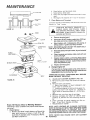
CLEAN AIR CLEANER
ELEMENT
(FIG. 25)
Remove two cover knobs and remove air cleaner
cover.
b. Remove foam pre-cleaner.
-Wash pre-cfeaner
in liquid
detergent
and
warm water to remove dirt.
-Wrap pre-cfeaner
in cloth and squeeze dry.
Lightly coat foam with engine oil.
Squeeze in
rag or towel to remove excess oH. Do not saturate.
c. Remove two nuts from top of cartridge.
d. Remove
cartridge
and clean air cleaner
body
carefully
to prevent
dirt form entering
carbure.
tor.
e. Clean cartridge
by gently tapping
on flat surface. if very dirty, replace cartridge.
f. Reassemble
air cleaner.
NOTE: NUTS HOLDING AIR CLEANER CARTRIDGE
MUST BE INSTALLED WITH FIBER WASHERS DOWN
ON CARTRIDGE PLATE TO PREVENT DIRT FROM
ENTERING CARBURETOR. TIGHTEN NUTS BY HAND.
OVERTIGHTENING COULD COLLAPSE CARTRIDGE.
NOTE: NEVER
REMOVED.
RUN ENGINE WITH AiR
CLEANER
MAINTENANCE
5.
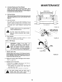
Lubricate Steering and Front Wheets
There is a grease fittin(] on each front wheel. Use a
grease gun; give eacn grease fitting two shots of
extreme pressure lubricating grease. Use 3O weight oil
to lubricate front spindles (Fig. 26).
6.
GREASE
FRONT
BOTH
WHEELS
Oil Pivot Points
Place several drops of SAE 30 oil at points where metal
parts move against each other, see Lubrication Chart,
page 20.
7.
tt
t|
O
tl
Clean Air Screen
\
Air screen (Fig, 18) must allow free-flow
o fair to
prevent
engine
damage
from overheating.
Clean
with a wire brush, compressed
air or water pressure
to remove
dirt,
chaff,
stubborn
dried gum and
fibers,
/
"OIL
SPINDLES
FIGURE
ALWAYS
USING
WEAR
SAFETY
COMPRESSED
DO NOT
DER OR
GLASSES
26
WHEN
_--_
AIR.
TOUCH
HOT MUFFLER,
FINS AS CONTACT
MAY
"
CYLtNCAUSE
S'_'_\_#_
f-
__
,030" (0,752 mrn)
FEELER GAUGE
BURNS.
SPARK"
PLUG
8. Check Muffler
Inspect and replace corroded muffler
create a fire hazard and/or damage.
Every
100
DISCONNECT
FORE
MAK|NG
MENT
OR
TOR),
HOT
Replace
SPARK
PLUG
ACCaDENTAL
ANY
REPAIR
BE CAREFUL
ENGINE
WIRE
INSPECTION,
TO
AVOID
OR MUFFLER
TO
BE-
ADJUSTCARBURETOUCHING
COMPONENTS.
Spark Plug
Replace Spark Plug, using a 13/16"deep well socket,
at the begining of each mowing season or every 100
hours, whichever comes first. Gap should be set at
0.030 inch (0,762 mm) (Fig. 28).
2.
3.
28
\
STARTING
(EXCEPT
"_ ._"T_
FIGURE
Hours
PREVENT
1.
as it could
_
Replace Air Cleaner Paper Cartridge
(Refer
to page
Replace
In-Line
FIGURE 29
and PreoCleaner
18),
Fuel Filter
If fuel filter is clogged,
obstructing
fuel flow to
carburetor,
replacement
is required.
a. With engine coot, remove
filter and plug fuel
line sections
as removed
from
both ends of
fuel filter (Fig,
29).
b. Place new fuel filter in position
in fuel fine.
]
BE SURE
THERE
ARE
NO
FUEL
LEAKS
AND
THAT
FUEL
LINE
PROPER POSITION
IN HOSE CLAMPS.
LINE
IS 1N
1
19
TENANCE
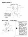
LUBRICATION
SPINDLE
(_ WHEEL
{_
MOWER
CLUTCH
(D SAE MOTOR OIL- 30W
@ EXTREME PRESSURE
LUBRICATING
GREASE
@ REFER TO ENGINE OIL
PUMP @
SPECS (PAGE 16)
(_ SAE MOTOR OIL 10W30
API- SFiCC
REPAIR & ADJUSTME
FOR ANY ADJUSTMENTS,
INSPECTION
OR MAINTENANCE:
1. PUSH
TRACTOR
CLUTCH/BRAKE
PEDAL
COMPLETELY
INTO
BRAKE
POSITION.
2. MOVE MOTION CONTROL LEVER TO
"NEUTRAL"
POSITION.
3. PLACE
PARKING
BRAKE
IN
"ENGAGED"
POSITION. REMOVE
FOOT FROM
PEDAL.
4. PLACE
ATTACHMENT
CLUTCH
SWITCH
1N
"DISENGAGED"
POSITION.
5. TURN
IGNiTiON
KEY TO "OFF"
POSITION.
6. MAKE
ABSOLUTELY
SURE
THE
BLADES AND ALL MOVING
PARTS
HAVE COMPLETELY
STOPPED.
7. REMOVE THE IGNITION
KEY.
8. DISCONNECT
THE
SPARK
PLUG
WIRES
FROM THE SPARK
PLUG
AND KEEP WIRE
AWAY FROM THE
PLUG
TO PREVENT INJURY FROM
ACCIDENTAL
STARTING.
BE CAREFUL
TO AVOID TOUCHING HOT ENGINE OR
MUFFLER COMPONENTS.
NEGATIVE
{BLACK
TERMINAL
CABLE
_ATTE
NT
RY
POSITIVE
tRED CABLE/
TERMINAL
FIGURE 30
2O
REPAIR & ADJUSTMEN
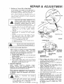
7,
S,ttrting your Tr*ctor With.
Wo*k _sttoty
If your battery is too weak to start the engine, it
should be recharged. If "'jumper cables" are used
for emergency starting, follow this procedure;
NOTE:
VOLT
YOUR
TRACTOR
NEGATIVE
VEHICLE
GROUNDED
IS
EQUIPPED
GROUNDED
SYSTEM.
MUST
ALSO
SYSTEM.
LEAD-ACID
BE
A
12
8ATTER|ES
WITH
VOLT
BATTERIES,
GENERATE
ALWAYS
WHEN
WEAR
AROUND
12
THROTTLE
CA_!
NEGATIVE
PLOSIVE
GASES.
KEEP SPARKS,
AND SMOKING
MATERIALS
AWAY
TECT]ON
A
THE OTHER
EYE
CLAMP SCREW
EXFLAME
FROM
HOLES "A"
\
PRO_
BATTERIES.
a.
Connect
each end of the RED came to the
POSITIVE
(+)
terminals
of each
battery
(taking
care
not
to short
against
chassis)
(Fig. 30).
b. Connect
one end of the BLACK
cable to the
NEGATIVE
(-)
terminal
of fully
charged
battery.
c. Connect
the other end of the came to the L,H,
side
pane!
bolt
(Fig.
14).
NOTE,
KEEP
AWA Y FROM GAS TANKAND
BATTERY.
d. Disconnect
cables in reverse order:
t. L.H. side pane/ bo/t (Fig. t4).
2. Negative
termina/
of fufly charged battery.
3. Positive termina/s.
I
_
DO NOT
_
TERY
2.
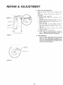
Throttle
Control
USE YOUR
TO START
Cable
TRACTOR
OTHER
BAT*
VEHICLES,
[
THROTTLE
CAB
FIGURE
CARBURETOR
!
J
Adjustment
Never attempt
to change maximum engine speed.
This is preset at the factory
(3600 +- 100 RPM)
and should only be changed by a qua/flied service
technician who has the necessary equipment.
a. Remove hood (page 23).
b. Loosen casing clamp screw until throttle cable
is free to move.
c. Move throttle
control
(on the dashboard)
to
""FA S T" position.
d. Pull throttle
cable tight (until swivel
below
carburetor
is against side of quarter
cffcle).
Retighten
casing clamp screw.
3,
\
IDLE SPEED
ADJUSTING
SCREW
MA_
JET COVEI
(HIGH SPE
iDLE MIXTURE
VALVE
GOVERNOR
CONTROL LEVER
FIGUR,
b. Start
engine and a/low
to warm for 1
minutes.
Make final adjustments
with on9
running and choke pushed in.
c. Move throttle control lever (on dashboard)
"SL 0 W" position.
Carburetor Adjustment
d. Hold governor control lever against idle sp,
NOTE:
ADJUST
THROTTLE
CONTROL
CABLE
screw, and adjust idle speed screw to obt
BEFORE
MAKING
ANY
ADJUSTMENT
TO CAR1200 to 1400 RPM (Fig. 31).
BURETOR. AIR CLEANER MUST BE ASSEMBLED TO
e. While stiff ho/dinq the governor control/E
CARBURETOR
WHEN RUNNING ENGINE,
against
idle speed screw, turn idle mixt
valve slowly
clockwise
(_-_) (lean mixt,
Minor carburetor
adjustments may be required to
compensate
for differences
in fuel, temperature
until speed just starts to slow.
or altitudes
Adjust the carburetor
fuel mixture
f. Turn idle mixture valve back to the midpc
as follows:
between rich and lean.
g. Adjust the idle speed screw to obtain 90_
1200 RPM. Release governor control lever.
PAGE
REFER13. TO "STARTING
THE ENGINE," 1
h. Move throttle
control
(on the dashboard)
"FAST. "" if engine hesitates or dies, turn
a. Gendy
turn idle mixture
valve clockwise
mixture
valve approximately
1/8 turn coun
(_.)
(Fig. 32) until it just doses and then
clockwise
(_-_)
until engine will acce/e,
counterclockwise
(._-, ) 1_!/2 turns.
as throttle
control
is moved from "SLC
to "'FAST. ""
CAUTION:
Valve may be damaged if turned 21
& ADJUSTMENT
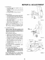
4.
INPUT
Drive
Belt Replacement
Park
the tractor
on level area. Engage parking
brake.
NOTE: BELT INSTALLATION
DECAL UNDER LEFT
FOOT R EST.
a, Remove mower (page 23).
b, Remove
belt
from
(3)
stationarv
idlers
(Fig. 33).
c. Re/ease
parking
brake,
Puff belt
as far as
possible over top of clutching
pulley (Fig, 33),
d. Reset parking
brake,
Puff belt over top o/
clutching
pulley.
e. P/ace top side of bett
between
blades
of
fan and rotate
fan counterclockwise
/P ..... )
(Fig,
34),
Remove
belt
from
#_put pulley
(Fig, 34).
f, Using a 9/16"
wrench, remove clutch /ocator
(Fig. 33- Inset),
g. Disconnect
clutch wire harness,
h, tnsta//
belt
by reversing
above
procedure,
NOTE:
REPLACE ONLY WITH BELT LISTED tN
REPAIR
PARTS SECT!ON OF THtS MANUAL.
PULL[Y
FIGURE
Motion
33
5. Fuse Replacement
Fuse is Located under dash
battery, If Fuse replacement
place with 30 Amp Automotive
Fuses can be purchased at
Centers and most retail stores
./
-
FIGURE 34
/
TRACTION
DRtV[
GELT
to the left of the
is necessary, Retype plug in Fuse.
al! Sears Service
REPAIR
6.
Hood Removal
a.
b.
c.
d.
7.
& ADJUSTMENT
Lift
hood.
Disconnect
headlight
wiring
connection
(Fig. 361,
Unscrew
one screw at rear of each side panel
(Fig. 35).
Pivot hood and side panel forward and tilt off
tractor (Fig. 36).
To replace, reverse the above procedure.
Mower
Removal
SCRE
a.
Remove mower belt per instruction under "Mower
Drive Belt Removel" through step D (page 11).
b. Pull retainer
springs
out of rear suspension
trunnions.
Remove
rear suspension
trunnions
from lift brackets (Fig. 3 7),
c, Pull
retainer
spring
out of rear hinge pin.
Remove rear hinge pin.
d, Puff retainer
spring out of front
hinge pin,
Remove front hinge pin (Fig. 37).
e. Use rift lever to raise suspension
arms, Slide
mower out from under tractor.
NOTE: IF AN ATTACHMENT
OTHER THAN THE
MOWER DECK IS TO BE MOUNTED ON THE TRACTOR, THE
L.H, AND
R.H, SUSPENSION
ARMS
(FIG, 37) SHOULD BE REMOVED FROM TRACTOR,
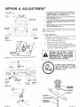
8.
Level
Mower
35
FIGURE
36
Housing
WIRE
CONNECTION
Adjust the mower while tractor is parked on level
ground or driveway. Make sure tire pressures are 14
PSI (1 kg/cn£) in front tires and 12 PSI (0.84 kg/cn'F) in
reartires. If tires are over or underinflated, you will not
properly adjust your mower.
Side-to-Side
FIGURE
Mower
Adjustment
a.
Depress rift lever plunger and use lift lever to
raise mower
to maximum
cutting height.
b. Measure height from bottom
of cull to ground
level at front of mower,
Distance
"A'" should
be the same on both sides of mower
(Fig. 38).
c. If distance
"'A "" needs to be changed, snap out
access hole cover on L.H. side above footrest.
Use 11/16"
wrench
on nuts "B" and "C" at
side-to-side
adjustment
trunnion
(Fig, 39).
d, To raise left side of mower,
loosen nut "'B'"
and Ugh ten nut "'C':
e. To lower left side of mower,
loosen nut "'C'"
and tighten nut "B"
NOTE: ONE ROTATION
OF ADJUSTMENT
NUTS
IS
EQUIVALENT
TO
APPROXIMATELY
3/16"
HEIGHT CHANGE,
f. Be sure all nuts are securely
tightened.
Front- To-Rear Mower Adjustment
a. To obtain the best cutting results, your mower
housing should be adjusted so the front and rear
flange distance
"D" (Fig. 40) is 1/2" (12.7 ram)
\'\ "\, _
",
RH
z -_.
i:i
RETAINER
SPR INGS
_,
"'
lower in front when the mower is positioned in the
highest cutting position,
NOTE: MEASURE DISTANCE "D" FROM GROUND
LEVEL TO BOTTOM OF CURL ON RIGHT REAR
FLANGE AND COMPARE TO DISTANCE
"D" AT
BOTTOM OF CURL ON RIGHT FRONT FLANGE,
FIGURE 37
23
REPAIR & ADJUSTMENT
b.
To raise rear of mower, loosen nut "E"on both rear
suspension arms. Screw both nuts "F" up an
EQUAL NUMBER OF TURNS (Fig. 41).
c.
When distance "D" is I/2" (1.27 cm) lower at front
than rear, tighten nuts "E".
To lower rear of mower, !oosen nut "F" on both rear
suspension arms an EQUAL NUMBER OF TURNS
(Fig. 4!).
d.
e.
OF CURL
_
\
,
[
i
--_ ':_
r'k-L ...........
....
L_=
_i::,-.
BOTTOM
_-_1
; OF CURL
_ i L
!
NOTE: WHEN ADJUSTING
NIONS, ALWAYS ADJUST
WILL STAY LEVEL.
.
GROUND
LEVEL
GROUND
LEVEL
FIGURE
38
SlOE.TO.SiDE
When distance "D" is 1/2"(1.27cm)
than rear, retighten nuts "E".
REAR SUSPENSION
TRUNBOTH EQUALLY SO MOWER
Blade Replacement
Raise mower
to highest position
to permit access
to blades or remove mower
(page 23),
a. Remove
bolt, /ockwasher
and washer (Fig. 42)
(turn counterc/ock
wise) ( f-_', ),
b. Remove and discard old blade.
c, Clean top and bottom
of mower housing.
do Instatl new blade with SHARP EDGE DOWN and
secure with fiat washer, lockwasher
and hex
head bolt. TIGHTEN SECURELY.
_
ALWAYS
ADJUSTMENT_
NUT
"8"
USE
GRADE
5
HEAT
J
BLADES, CHECK BOLTS IN BLADES
TREATED
BOLTSTO TO
OCCASIONALLY
MAKEATTACH
SURE
BOLTS ARE TIGHT. TORQUE BOLTS
TO 30_35 FT. LBS, (41-47 N-M).
TRU_
FIGURE
Iower at front
39
\
\
REAR
A GRADE 5 HEAT TREATED BOLT
CAN BE IDENTIFIED
BY THREE
LINES ON THE BOLT HEAD AS
SHOWN AT LEFT.
f
SUSPENSION
BOTTOM
OF CURL
FIGURE
40
MANDREL
ASSEMBLY
FLANGES
WASHER
LOCKWASHER
HEX BOLT
(GRADE 5) "_
ADJUSTMENT
I0,
11.
.012 INCHES
(0.3048 ram)
Rear Wheel Replacement
Coat axle with grease to prevent
corrosion
or rust
accumulation
and eventual
seizing of wheel hub
to axle shaft.
Electric
Clutch
Adjustment
(3)
The electric clutch should provide years of service.
The clutch has a built-in brake that stops the pulley
within 5 seconds,
Eventually, the internal brake wilt
wear so the mower blades wilt not stop as recommended,
Adjustment
should be made by a Sears
technicia n,
CLUTCH
PLATE
BRAKE
Make sure attachment clutch and igniton switches
are in the "off" position.
a.
b.
Adjust the three nylon locknuts "t3" until the space
between the clutch plate and rotor measures.O 12°'
(0.305 ram) at all three slot locations cut in the side
of the brake plate (Fig. 44).
ROTOR
NOTE:
AFTER INSTALLING NEW ELECTRbC CLUTCH,
RUN TRACTOR AT FULL THROTTLE, AND ENGAGE AND
DISENGAGE ELECTRIC CLUTCH t0 CYCLES TO WEAR
tN CLUTCH PLATE.
NYLON LOCKNUT"B"
FIGURE
44
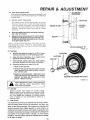
12. Tire Care
a.
Maintain tire pressure in front at 14 PSI (1 kg per
crrF) and rear tires at 12 PSI (0.84 kg per cn£).
b.
Keep tires free of gasoline, oil, or insect control
chemicals which can harm rubber.
c.
Avoid stumps, stones, deep ruts, sharp objects
and other hazards that may cause tire damage.
d.
Removing wheel for tire repair (Fig. 45).
WASHERS
KLIP RiNG
HUB CAP
t. Block up axle securely.
2. Remove hub cap, klip ring and washer to allow
wheel removal (rear wheel contains a square
key - Do Not Lose).
3. Repair tire and reassemble. Align slots in rear
wheel hub and axle. Insert square key. Replace
washers and snap klip ring securely in axle
groove. Replace hub cap.
SQU_RE KEY (REAR TiRE ONLY)
FIGURE
&
1
WHEN
MOUNTING
TIRES,
UNLESS
ARE
SEATED,
OVER
INFLATION
CAUSE AN EXPLOSION,
BEADS
CAN
|
J
13. Storage
Remove mower from tractor for winter storage.
When mower is to be stored for a period of time,
clean it thoroughly, remove aH dirt, grease, leaves,
etc. Give blades and underside of housing a good
coat of grease or rust preventative.
Store in a
clean dry area.
A.
Fuel System
It is important to prevent gum deposits from forming in essential fuel system parts such as the carburetor, fuel filter, fuel
hose, or tank during storage. Also, experience indicates that
alcohol blended fuels (called gasohol or using ethanol or
methanol) can attract moisture which leads to separation and
formation of acids during storage. Acidic gas can damage the
fuel system of an engine while in storage. To avoid engine
problems, the fuel system should be emptied before storage
of 30 days or longer.
45
REPAIR
B.
C°
ADJUS
Engine Oil
Drain (with engine warm) and replace with clean
engine oil. (See chart, page 16).
D,
Cylinders
1.
2.
Remove spark plug.
Pour I ounce (29.5 ml) of off through spark plug
holes into cylinder.
3.
Tum ignition key to "START" position for a few
seconds to distribute oil.
4.
Replace with new spark plug.
E.
Battery
1. Prior to storage, clean terminals and top of
battery.
Remove cable from positive battery terminal
2. After a period of time in storage, battery may
require recharging.
General
Clean
foreign
Cteaning
engine,
matter,
battery,
seat,
finish,
etc.
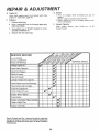
SERVmOE RECORD
IN DATES
COMPLETE
REGULAR SERVICE
SERVICE
1
Chart_ge Engin
Check Brake Operation
i
m
|
Check Tire Pressure
Clean Air Screen
Clean Air Cleaner
Lubricate Tract_
Check Battery_ _evel and Recharge
Clean Battery_ ind Terminals
Carburetor Adj. Jstment
Check Engine Oil Level
,,,,
,,
Sharpen Mower Blades
Check Muffler
Replace
v'
,_aner Paper Cartridge
v'
i/
Replace Spark Plug
Replace Fuel :itter
_
[
Sears, Roebuck and Co., reserves the right to make any
changes in design or improvements without imposing any
obligations to install the same upon its items heretofore
manufactured.
26
DATES
of
a//
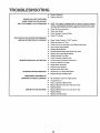
TROU
PROBLEM
LESHOOTING
Cause/Remed
WiLL NOT START
Push Clutch/Brake
Pedal into Brake position
Move Attachment Clutch Switch to "Disengaged"
position
Fill Tank with Gasoline. Check Fuel Line and Carburetor (clean if
necessary), Replace Fuel Filter. Use Fresh Fuel
r
Check Fuse for fault and replace
Recharge or repiace Battery
,[email protected]
Oheck Wiring
Replace Spark Plug(s) and adjust gap
WiLL NOT TURN OVER
r
Push Clutch!Brake Pedal into brake position
Charge or replace Battery
Recharge or replace Battery
Move Attachment Ciutch Switch to "DISENGAGED"
position
Replace Ignition Switch
Replace Interlock Switch(as)
Replace Solenoid or Starter
Check for fault and replace Fuse
Check all Wire Connections and "Ground" Points
|
ENGINE CLICKS BUT
WON • T START
Clean Battery Terminals
Replace Starter or Solenoid
Charge or Replace Battery
Check Wire Connections and "Ground" Points
HARD TO START
Place Throttle Control in "FAST" position and run starter several times
to clear out gas
Remove Air Cleaner and clean
Replace Spark Plug(s) and adjust gap
Recharge or replace Battery
Check the Wiring
Drain Fuel Tank and Carburetor, Use Fresh Fuel. Replace Fuel Filter
Make necessary adjustments to Carburetor
Major Engine Overhaul
ENGINE MISSES OR LACKS POWER
r
Shift to a lower gear or reduce load
Drain Gas Tank and Carburetor, Use Fresh Fuel
Remove and clean Air Cleaner
Make necessary Carburetor adjustments
Clean Air Screen
Add or change oil
r
Replace Spark Plug(s) and adjust gap'
Check for loose wires
Replace Fuel Filter
Major Engine Overhaul
ENGINE OVERHEATS
Shift to lower gear or reduce load
Clean Air Screen
Add or change oil
Clean Engine Cooling Fins
Remove and clean Muffler or replace
Remove and clean Air Cleaner
Use fresh fuel and adjust Carburetor
Drain and replace oil for proper temperature
_O LIGHTS
Check Fuse, Switch and Wire Connections.
Replace Switch
WON'T CHARGE
Check Fuse for fault and replace
RepLace Battery
27
Replace Headlight Bulbs
TROU
LESHOOTING
_-
Replace Regulator
_r
Replace Alternator
ENGINE WILL NOT SHUT DOWN
WHEN OPERATOR
WITH ATTACHMENT
LEAVES SEAT
CLUTCH ENGAGED
,_"
NOTE: This tractor is equipped with an operator presence sensing
system. Any attempt by the operator to leave the seat with the engine
running andthe attachment ctutch engaged wift shut down the engine,
Check all Wire connections
_-
Check Seat Switch
__"
Check Operator Presence Relay
Check PTO Switch
UNSATISFACTORY MOWER PERFORMANCE
UNEVEN DISTRIBUTION OF CLIPPINGS ,_
Place Throttle Control in "FAST" position
Check air pressure in Tires
Check front-to-rear and side-to-side Mower adjustment
Use a slower ground speed
MOWER BLADES WiLL NOT ROTATE
,r
Replace Mower Blades
,r
Reinstall Mower Blades with Sharp Edge down
=_
Replace with proper Mower Blades
r
,r
Readjust Mower Drive Belt
Clean underside of Mower Deck
,_
Correct Clutch mechanism
,r
install new Mower Drive Belt
interference
Adjust Mower Drive Belt
EXCESSIVE MOWER VIBRATION
r
Replace frozen Mandrel
,r
Replace frozen Idler Pulley
,_"
Replace bent or unbalanced Blades
w-
Replace Mandrel. Replace Deck
w-
Set Throttle for maximum engine speed
,_
w-
Let grass dry out
Clean underside of Mower Deck
,r
Readjust Mower front-to-rear
WINDROWING STRIPPING OR
DROPPING OF GRASS CLIPPINGS
and side-to-side
Replace Blades
UNEVEN CUT OR SCALPING =r
Readjust Mower front-to-rear
=t
Replace Blades
,="
Replace bent Mandrel(s)
_28
and side-to-side
18 HP 38 °° RiDiNG TRACTOR = o MODEL NUMBER 917o254740
SCHEMATIC
4..
RED
12V
_
BLACK
RED
TILLERATTACH
CONNECTOR
1CLUTCH/BRAKE¿
I
POWER
TAKE-OFF
SWITCH
(CLUTCH
OFF
RED
Q
S
2 TURNS
CLOCKWISE
FROM FUSE
D
E '
(PEDALUP)
t
t
BLACK
BLACK
WHITE
BLACK
BLACK
FUSE
IGNITION
SWITCH
IGNITION
UNtT
30 AMP
SPARK
PLUGS
BLACK
©
@
BLACK
BLACK
RED
ASSEMBLY
ENGINE COIL
IGNITION
SWITCH
POSITION
CIRCUIT
OFF
M_
ON
B-L
START
B-S-L
LIGHTS WILL NOT REGISTER
5 AMPS DC (POS.)
22 MAC (MIN.)
5 AMPS DC
(ALTERNATOR)
ORANGE
NOTE: WITH ENGINE
BROWN
RUNNING @ 3600 RPM.
BATTERY IN-LINE
LIGHTS OFF
LIGHT
SW_TCH
ON AMMETER
PTOSWITCH
YOUR TRACTOR IS EQUIPPED WITH A SPECIAL ALTERNATOR SYSTEM. THE LIGHTS ARE NOT CONNECTED TO THE
BATTERY, BUT HAVE THEIR OWN ELECTRICAL SOURCE.
BECAUSE OF THIS, THE BRIGHTNESS OFTHE LIGHTS WiLL
CHANGE WiTH ENGINE SPEED. AT IDLE SPEED THE LIGHTS
WILL DiM, AS THE ENGINE iS SPEEDED UP, THE LIGHTS
WILL BECOME THEIR BRIGHTEST.
CRCUIT
OFF
B&E,C&D
ON
B&A
CHASS
GROU_,
REMOVABLE
CONNECTIONS
WIRING INSULATED CUPS
NOTE: IFWIRING INSULATED CLIPS WERE REMOVED FOR
SERVICING OF UNIT, THEY SHOULD BE REPLACED TO
PROPERLY SECURE YOUR WIRING.
POSITION
29
NON-REMOVABLE
CONNECTIONS
:_EPAIR PARTS
18 HP 38" RiDiNG TRACTOR--
MODEL NUMBER 917=254740
=LECTRICAL
5O
46
10
29
31
o
\
2
45
4
Electric
Clutch
2
REPAIR PARTS
18 HP 38" RIDING
ELECTRICAL
KEY
NO.
¢¢
TRACTOR
-.. MODEL NUMBER
917.254740
PART
NO.
DESCRIPTION
KEY
NO.
PART
NO.
1
2
3
4
4152J
1 I0859X
4022J
4021J
BulbL_#Tt
Harness - Light Socket
Nut - Hex
Switch
- Attachment
Clutch
5
109310X
Key Set
6
7
8
9
10
t09788X
109787X
4406R
1 t07t2X
106315X
JVut - ignition
Bezel - Ignition
Switch - /gn/t_b_
Switch - Light
Diode Assembly
I02476X
4207J
4206J
125619X
10908 tX
719J
11
12
13
14
15
16
17
18
19
4799,t
122822)(
!08824X
10250tX
I09553X
100541X
109596X
7603J
72240460
Cable, Battery
A,',,mieter
Fuse - 30 Atop
W_re Loop
Switch - /n_erlo',;k
CiutU;
Pedal
Tub_> - Battery
TTay
Clan _/J - Ho,_
Tray - Battery
Bolt - Rd. Hd. Sq. Nk, 1/4 - 20×
28
29
3O
31
32
33
34
35"
36
37
38
39
20
21
22
23
24
t2t537X
STD541025
STD551t25
STD55t025
74760412
Battery
*Nut - Hex 1/4
"WasherLock
"Washer 9/32 x
*Bo!t - Hex 1/4
27
t23t98X
+Nut
41
42
43
45
46
47
48
49
50
; 5t
52
7.12
- 2,,0
1,44
5/8 :_ 16 Ga,
, 20 x 3/4
Wm_j t/4-20
DESCRIPTION
10090400
STD541225
74780408
1 I050400
73510400
17021008
71050600
I21305X
STD523710
I09748X
2751R
235R
74780408
76380400
I2!264X
71031008
73951000
101539X
126409X
Guard-
Terminal
Cable, Ground
Cable- Battery
HarnessIgnition
Solenoid
Cover.
Terminal
WasherLock !/4
*Nut - Jam I/4- 20
*BoltHex 1/4 - 20 x 1/2 Gr. 5
Washer- Lock - Ext.
NutKeps !/4- 20
Tooth
!/4
Screw - Tap Hex Head 10- 24 x l/2
Type T
Washer, Lock _ Ext, Tooth _/.8
S',_,,;ch Assembly
* Bolt, Fin. Flex 3/8- !6 x 1
Relay
Clip,
Clip,
Bolt
Nut
Assembly
Fuel Line
insulated
t/4-20x
t/2
Crowzdo_.k
l/4
- 20
Battery
Caps
Screw, Hex Washer Hal, 10.32
Keps Nut I0- 32 UNF
Sheet,
instruction,
Tractor
Owners Mazs.',_al
x 1/2
15 u Slope
NOTE: All component dimensions given in U.S. inches.
1 inch = 25.4 mm
+S TA NDA R£) HA R D WAR E--PURCH/,I
A
B
D
E
F
G
@34
@ 35
48
39
._ 37
@38
@ 52
41
(_
49
SE L OCA L L Y
REPAIR PARTS
18 HP 38" RIDING
TRACTOR
- - MODEL NUMBER
917.254740
CHASSIS
lOi
\
/
/
99
!02
y/-53
38
45
09
16
D
28
41
14
D
25
30
32
REPAIR PARTS
18 HP 38" RiDiNG
TRACTOR
- = MODEL NUMBER
9!7.254740
CHASSIS
KEY
NO.
PART
NO.
t
2
3
4
5
6
7
DESCRIPTION
KEY
NO.
120039X
124294X
105513X
I2 I642X
t06202X
t 0580 t X
105511X
Seat
Pan - Seat
Bracket - Pivot - Seat
Fender
ReflectorRear
Decal
Strap - Fender
8
9
I0
121250X
124181X
105531X
Spring - Compression
Spring- Compression
Nut - Push
t t
12
13
t4
15
t6
!7
I8
I05509X
t06082X
124118X
105525X
121794X
4900J
105465X
105466X
19
20
21
22
23
24
25
26
27
28
29
DESCRIPTION
PART
NO.
Bolt - Shoulder
5/16 - 18
Nut- Lock 5/1618
"Washer - Lock !/2
61
62
63
65
66
67
t05529X
73680500
STD557 t50
106974X
73680600
174906 t 2
6"8
69
70
19171912
STD523710
72170410
Bracket - Fender
Pad- Spacer
Panel- Dash - L.H.
BracketSupport _ Dash
Cover - Access
Decal- Clutch/Brake
Footrest - L. H
Pad- Footrest
71
72
73
74
75
76
78
STD533707
STD523707
19131312
STD522505
73680400
108067X
17490612
12!2t5X
123549X
!06020X
3645J
87!0J
123487X
121306X
235R
121277X
!25963X
5277J
DecalDrive Belt
Cap- Fuel
Tank- Fuel
Bushing
StemTank, Fuel
Clamp - Hose
Drawbar
Clip - Insulated
Chassis Assembly
Decal, Automatic
Line- Fuel
80
17490608
8I
84
85
86
87
88
89
92
94
17490616
!23976X
t06909X
1069 tOX
108402X
121248X
124238X
t2 !246X
2751R
30
120166X
Decal,
95
1 !0436X
31
120579X
Pal Nut
35
36
37
1090t5X
109016X
110828X
BracketPivot - L.H.
Bracket _ Pivot - R,H.
Panel - Dash - R.H.
38
40
41
42
5320R
105464X
108403X
1068t4X
Clip - ln.£u/a ted
Footrest
- R. H,
Panel _ Side - R.H.
Decal. Stripe, Side Panel.
43
t I0350X
44
45
46
47
48
50
t085!2X
t05568X
I05806X
105528X
I06003X
I085t3X
51
52
53
54
55
t 10897)(
t06004X
I06091X
106090X
! 084 ! OX
Bezel- Headlight
Lens- L.H.
Hinge- R.H.
Hinge
L.H.
Panel _ Side - L.H.
*STANDARD
56
57
60
I06813X
126312X
106013X017
Decal - Stripe,
Decal, 18 HP
Hood
NOTE: All component dimensions given in U.S. inches.
1 inch = 25.4 mm
A
Chassis
Strap Assembly-
R.H.
Grill
C
D
Side Panel _ L H.
E
97
F
57 @95
_62.
t_66
M
S
T
G
S9
t_66
V
,oo
If,° ,oo
e
107
19131614
9Y
98
99
lj,_
107
t 02
!04
105
74780816
121144
121249X
915_R
1068 t 7X
105953X
750211
I21251X
33
Nut, Hex, Large
Screw- Special
Washer
Bolt 1/2. I3 x 1
Shoulder
Bolt
Spacer,
Split
Foam Strip
Air Duct
Decal made in USA
Foam strip 9/32 ID x 3/8
Slotted
Iit
105838)(
Retainer,
t 12
114
It5
105839X
74760616
19131316
Receptacle,
_)86
@73
Stud,
pan
I/4
¢7s
HD. screw
10 -32 x 1/2
UNF
Turn
I/4
Turn
I/4
Turn
Bolt, Fin. Hex,
3/8 - t6 UNC x !
Washer
x I3/t6
13/32
HARDWARE-PURCHASE
72
Ftangetock
U-Chip
Nut keps 10-32
Clip insulated
Heat Shield
.71
Rothng
Bushing,
snap
Cap - Sprinq
Bracket, switch mount
Clip
Gromrnet
- Split
Washer 13 '32x 1, 14 Ga
74641008
K
Thread
Screw, Hex Wsh. Thd, Roll.
3/8 -16 x 1/2
Screw 3/8 - I6 x t/2
73951000
4171R
I08105X
123650X
j
I6
Pal Nut
Screw - Hex Washer
3/8 . 16 x 3/4
I07
108
t09
110
H
S9
_31
96
3/8-
Screw- He× Washer Thread Rot/im_l
3/8,
16× 3/4
Washer 171'32 x 1-3/16 x 12 Ca.
*BoltHe× 3,/8- I6x
1
Bolt carriacfe 1/4 x 1 - 1/4
"Bolt - Carriage 3/8 - 16 x 3 4
*Bolt - Hex 3/8 - 76 x 3/4
Washer t3/32 x 13/16 x I2 Ga
"BoltHex 1/4 . 20 x 1'2
Nut- Hex 1/4- 20
106
BracketPivot - R,H.
• Decal- Stripe
Decal
Grill
Lens- R.H.
Bracket.
PivotL.H.
B
6!
- R.H.
Decal
Nut, Lock
L
x t6 Ca.
L OCA L L Y
P
Q
R
x
w
@84
@
_tt5
81
@115 O 66
@ 8e
t8"7
REPAIR PARTS
18 HP 38" RIDING TRACTOR
DRIVE
- - MODEL NUMBER
100
98
99
4
,/
/
80
24
_4
917.254740
REPAIR PARTS
18 HP 38" RiDiNG
DRIVE
KEY PART
NO, NO.
1
2
3
4497H
1913136
124!48X
4
5
6
8545J
13200300
---
7
8
12
14
t5
16
17
18
19
20
21
__22
25
27
28
29
30
31
32
33
34
35
36
37
38
39
40
41
42
43
44
45
46
48
49
50
TRACTOR
.- - MODEL NUMBER
DESCRIPTION
108373X
13280336
124559X
123461X
2751R
121187X
I21!91X
123583X
73510600
121!89X
121199X
121748X
106108X
12000001
104757X
65139
59192
74610764
126197X
10040700
1261 !2X
109841X
100229L
19111212
123674X
4470J
19131312
I09070X
121218X
109169X
110422X
74760516
106888X
121200X
8883R
122424X
STD571810
124236X
A
KEY PART
NO. NO.
Clip, Hairpin
Washer 13/32x 13/16x !6Ga.
Engine, 18 H.P. Briggs and Stratton
Model Number 422707, Type
Number 1513-01
Gasket
Elbow, STD 90° 3/8 - 18 NPT
Plug, Pipe (Not Serviced, see page
47 for part number)
Muffler
Nipple
Control Throttle!Choke
V-Belt Drive
Clip, Insulated
Bracket, Mounting, Hydro
Bracket, Transaxle
Key, Square 2.5 x . 1845/. 1865
Nut, Keps 3/8- 16
U-Bolt 3/8- 16x2-7/8
Spacer, Split
Washer 25/32x 1-5/8x 16 Ga.
Rim, Rear, 8"
E-Ring
Cap, Hub, Rear
Stem, Valve
Cap, Valve
Bolt, Hex 7/16 - 20 x 4
Washer 1-1/2 x 15/32 x 1/4
Washer, Lock 7/16
Clutch, Electric
Pulley, Engine
Tube Assembly, Exhaust
Washer 11/32 x 3/4 x 12 Ga.
Idler, Flat
Spacer
Washer 13/32x 13/16x 12 Ga.
Keeper, Belt
Keeper, Belt, Engine, L.H.
Locator, Clutch
Spring, Brake Return
Bolt, Hex 5/16- 18 x 1
Spring, Rod, Brake
Rod, Brake
Cover, Pedal
Shaft, Foot Pedal
* Pin, Roll 3/16 x i
Cap
B
917.254740
C
D
E
(_)35
51
52
53
54
55
56
57
58
59
60
6!
62
65
66
t25637X
105710X
73680600
123205X
12000039
110812X
123789X
105709>(
123102X
STD523715
123766X
105706X
17720410
17490624
67
68
69
70
71
72
11050600
STD523707
STD523710
STD533707
76020412
STD54 !437
73
74
75
76
80
82
83
STD541237
STD551062
I20183X
I05730X
106268X
108236X
17021008
84
88
74760644
72140506
89
92
93
96
97
98
99
100
73680500
7152J
677VI
STD551125
STD522507
121522X
11050600
73610600
Rod, Brake, Park
Link, Clutch
Nut, Lock 3/8- 16
Retainer, Belt
Klip Ring
Washer, Hardened
Arm, Idler
Spring, Return, Clutch
Bracket, Clutch
*Bolt, Hex 3/8 - I6x 1-1/2
Pulley, Idler
Bearing
Screw, Hex Thd. Cut 1/4 - 20 x 5
Bolt, Hex Washer Thread Rolling
3/8- 16x 1-1/2
Washer, Lock Extemaf Tooth 3/_
* Bolt, Fin. Hex 3/8 - !6 UNC x 3/_
* Bolt, Hex 3/8 - 16 x 1
* Bolt, Carr. 3/8- t6 x 3/4
Pin, Cotter 1/8 x 3/4
* Nut, Lock Hex with Washer Inset
3/8 - 16
*Nut, Hex Jam 3/8 x 16
* Washer 21/32 x I x 16 Ga.
Bearing, Nylon
Keeper, Belt, Engine, RH
Tire 18 - 9.50 x 8
Bracket, Switch
Screw, Tapered Hex Head
No. 10 _ 24 x 1/2 Type T
Bolt, Hex 3/8 - 16 x 2-3/4
Bolt, Round Head, Square Neck
5/!6 - 18 x 3/4
Nut, Lock 5/16- 18
Tube (Not furnished with Tracto6
Spark Arrester Kit
* Washer, Lock, Heavy Helical Spl
* Bolt, Fin. Hex 1/4- 20 x 3/4
Control Choke
Washer, Lock External Tooth 3/_
Nut, Fin. Hex 3/8- 24 UNF
* STANDARD HARDWARE.
- PURCHASE LOCALL'
NOTE: All component dimensions given in U.S. inch_
1 inch = 25.4 mm
G
H
69
67
DESCRIPTION
@38
L
70
M
58
53 @ 53
N
83
P
88
89 @ 96
REPAIR PARTS
18 HP 38" RIDING TRACTOR
STEERING AND FRONT AXLE
\
-= MODEL NUMBER
917.254740
\
71
20
REPAIR PARTS
18 HP 38" RIDING TRACTOR
STEERING AND FRONT AXLE
KEY
PART
NO.
NO.
o- MODEL NUMBER
1
2
3
4
5
6
7
8
9
I05810X
100770L
73940800
I O0 7 ! 2K
t00713N
100711L
I060t5X
120028X
17490612
I1
12
13
14
5479J
STD541137
123186X
STD551043
Plug, Button
* Nut, Hex 3/8 - 24
Bracket, Chassis Reinforcement
* Washer
15/32 x 15/16 x 16 Ga.
16
t 7
18
19
20
2t
22
23
24
25
26
27
28
I21197X012
t08635X
i
12404IX
5707-9
124033X
71070410
124036X
STD551125
12000029
6266H
126684X
t08972X
124034X
Dash Plate
Decal - Instruction
Shaft.
Steering
Washer
Shaft, Pitman
Screw, Socket Hex
1/4-20x5/8
Bracket • Steering
* Washer, Lock !/4
Klip Ring
BearingThrust
Washer 5/8 x 1/4 x I6 Ga.
Washer- Phenolic
Gear - Sector
29
30
3t
32
33
34
35
36
37
38
42
43
44
45
46
47
48
49
50
52
53
54
55
56
57
58
59
60
61
62
63
.-.
64
124035X
12t748X
I055t8X
I2t236X'
2751R
STD523120
STD523707
t06001X
I554J
121 t95)(0
72
105663X
7475"1060
I05664X
124032)(
10040600
STD551131
12t334X
73810500
105656X
1 t0438X
t21749X
3366R
73901000
105669)(
I05654X
278H
65139
59192
9040H
106732X
! 06222X
59904
!04757X
Shaft, Support
Washer 25/32 x 1-5/8 x 16 Ga.
Dash- Lower
SF)acer
Clip, Fuel Line
*Bo/tHex 5/1618 x 2
"Bolt.
Hex 3/8 - 16 x 3/4
Support Plate - Battery
Bushmg - Steering
Saddle
Support - Saddle - Rear
Bolt . Hex 5/8.
! 1 x 3-3/4
SupportSaddleFront
LinkDrag
Washer, Lock Helical Spmr_g
*WasherLock 5/t6
Rod, Tie
"Nut.
Hex 5/I6 - 24
Spindle - L.H.
Spacer - Bearinq - Front Axle
Washer
25/32x
1/4x 16 Ga.
Bearing
Nut - Lock - Flange 5/8.
t I
Axteo Front
Spindle - R.H.
Fitting.
Grease
Stem- Valve
Cap. Valve
Bea ring
Rim _ 6" Front
Tire - Front
A
KEY
NO,
65
66
67
68
69
70
7!
72
73
74
75
76
77
78
79
8l
82
83
84
85
86
87
88
89
90
91
92
93
DESCRIPTION
B
D_ca/, - Cap, Steering
Wheel
Insert - Steering
Wheel
Nut=Hex Jam Toplook _/2-20 UNF
Washer
Wheel - Steering
Adapter
- Steering
Wheel
Sleeve . Steering
Dash
Screw, Hex Wsh. Thd, RolL
3/8- 16 x 3/4
C
Tube - Tire - Front
Cap- Hub. Front
D
E
(Not
F
furnished
G
tractor)
_
185 [_
DESCRIPTION
106933X
12t201X
t21631X
108196X
760204 I2
73680600
t 08200X
1085t8X
19212016
10820 t X
t2t202X
108844X
19132012
STD523730
I2t209X
!082!2X
121208X
S TD55 !037
I21204X
121206X
100536K
72110608
19171416
1743 t 008
72110620
t21235X
122819X
741805 t 2
73:!; 10500
17490508
96
97
98
t00
124037X
I23
124
19131212
1098!6X
17490608
2751 R
102670X
19272016
735t0605
732206
O0
74180412
19091216
73510400
73680500
492tH
19111216
STD523710
74561014
69180
121217X
19070816
17021008
11O739)(
17490512
121216X
73800600
t2t 190X
4497H
I21232X
Knob- Control
Rod. Control
SpringTorsion
Bracket - Control
Rod
Pin - Cotter 1/8 x 3/4
Nut - Lock 3/8 - 16
Washer- Friction
Bolt - Hex Shoulder
3/8, t6 × t 3 8
Washer 21/32 x I 1/4 x 16 Ga
Spacer
Link - Control
Spring- Compression
Washer !3/32 x 1. I ._4x 12 G.._
*BoltHex 3/8t5x 3
Arm Assemb/y - Pump Con tru /
Trunnion
Rod-Ad/ustab/e
Control
*Washer 13/32x
I3/76x
16 Ga
BeI/c?ank
Brkt. Bellcrank
Pivot
Shoulder
Bolt
Bolt . Carnage 3/8 . t6 x 1
Washer 17/32 x 7/8 x 16 Ga,
ScrewHex No. 10 16 x 1 2
Bolt -Carmaoe 3"8
16 x 2- _,4
Spacer
Screw, Special
Screw.
Crown Truss Head/
5/16t8 x 3/4
N,tt
Keps 5,'t6.
18
Screw- Hex Washer Thread Rolhng
5/I618x 1/2
Gear - Pff?ton
_I/asher 13 32 _ 3 4 _ 12 Ga
Nyhner.
Snap. In
Screw- Hex Washer Thread Rot/ing
3/8.
16x I"2
Ch;_ - Fuel Line
Spring - Compression
Washer 27/32 x 1,1/4 x !6 Ga.
_,ens N_Jr 5 8
_6
Fm.He.x Nut - 3 8
16
Screw t/4 - 20 x 3/4
Washer 9 32,
3 4,_ 16 Gu
Keps Nut " ; 20
Nut.
CrownLock
5 16 18
Spr_ng
Retainer
Washer 11/32 x 3/4 x t6 Ga,
* Bolt, Fin, Hex 3/8 - 16 UNC x 1
Screw, Hex Socket Head
10 - 24
Nut_ Lock 10 - 24 UNC
Guide Control
Washer 7/32 x 1/2 x t6 Ga.
Scr, Tap Hex. Hd. I 0 - 24 UNC x t/2
Washer, Spring
Screw 5/16x!8
x 3/4 TY-TT
Bracket Control Guide
Nut, Top Lock
Keeper, Centerspan
Clip, Hairpin
Cap,
Spindle
NOTE: All component dimensions given in U.S. inches.
1 inch = 25.4 mm
H
;_ 34
U
@ 88
PART
NO.
94
95
10t
102
!03
t04
105
106
107
108
t09
I10
1tt
t12
113
114
115
1t6
117
118
!19
120
12I
I22
with
917.254740
J
*STANDARD HARDWARE
K
L
M.
- - PURCHASE L OCALL Y
N
O
8,
91
1o4
107
37
lo8
70
REPAIR PARTS
18 HP 38" RIDING TRACTOR
LIFT ADJUSTMENT
- - MODEL NUMBER
917.254740
2
25
42
43
21
20_i
16
18
17---....
""
32
_
__C
_" ..
_
32 _.,._
32 --__'_"29
38
..._26
REPAIR PARTS
18 HP 38" RIDING TRACTOR
LiFT ADJUSTMENT
KEY
NO,
PART
NO.
1
2
3
4
5
6"
7
8
9
10
!1
!2
13
14
16
17
18
19
20
21
I00734K
STD541237
110729)(
76020308
2876H
1913 !016
73680600
191512!6
110810)(
105848)(
125631X
122384)(
121002X
747B_24
4939M
121006X
4921H
19171516
110029)(
121000)(
= ° MODEL NUMBER
DESCRIPTION
Knob, Height Adjustment
_Nut. Jam 3/8- 16
Rod. Adjust. Lift
Pin, Cotter 3/32 x 1/2
Spring
Washer 13/32 x 5/8 x t6 Ga,
Nut, Lock 3/8- 16
Washer 15/32 x 3/4 x 16 Ga.
Trunnion
Bolt, Shoulder 3/8_ 16
Grip. Handle
Plunger, Lever
Lever, Lift (inc, Key No. 17)
Bott 3/8- 16 x 1-I/2
Retainer Spring
Rod, Lever
Retainer Spring
Washer 17/32 x t5/16 x 16 Ga.
Link. Lift
Shaft. Lift
917,254740
KEY
NO,
PART
NO.
22
23
24
25
26
27
28
29
30
3t
32
33
34
36
39
40
42
43
110448)(
110447)(
73710700
12000037
I05864X
110739)(
121598)(
9135R
106308X
122365X
STD541050
121599)(
73980600
STD533707
73360700
t 10807)(
t 2000022
19292016
*STANDARD
DESCRIPTION
Link, Lift Adjust
Trunnion, Lift
Nut, Crowntock 7/16- 20 UNF
!<lip Ring
Bracket, Suspension
Washer, Spring
Arm, Suspension, R, H.
Retainer Spring
Trunnion, LifC Lower
Button, Plunger
_Nut. Hex Fin, 1/2 _ 13
Arm, Suspension, L, H,
Nut, Lock, F/ange 3/8 - ld
*Bolt, Carriage 3/8- I6 x 3/4
Nut, Hex Jam 7/I6- 20 UNF
Nut, Special
E.Rmg
Washer
HARDWARE--PURCHASE
LOCALL
Y
NOTE: All component dimensions given in U.S, inches.
1 inch = 25.4 mm
B
A
(_36
C
_
10
34
39
REPAIR PARTS
18 HP 38" RIDING
38" MOWER
TRACTOR
- - MODEL NUMBER
\
917.254740
_4-----75
__3o
!
t
B
A
_"
CC
55
B
4n
3
REPAIR PARTS
18 HP 38" RiDiNG TRACTOR
38" MOWER
KEY
NO,
PART
NO.
- - MODEL NUMBER
DESCRIPTION
KEY
NO.
917.254740
PART
NO,
t
t 06085X
V-Belt
27
2
3
4
5
121458X
84 t 7J
73680600
19I 112t6
Housing
Runner, R.H.
Nut, Lock 3/8
Washer
11/32
29
30
31
32
74760636
123552X
106902X
121316X
6
7
8
72740505
105896X
170452X
Bolt, Carnage 5/16
Bracket,
Deflector
Pushnut
33
35
36
106513X
I2t687X
100668L
9
10
t !
t2
t06734X
106735X
106736X
I08682X
Spring, Deflector
Rod, Hinge
Deflector,
Shield
DecalV-Belt
Drive,
37
17490614
39
40
122264X
19732012
!3
14
I5
16
17
18
19
20
2t
22
23
24
25
26
105304X
105662X
105744X
492 tH
t05872X
109835X
74 7606t2
73680500
109598X
!09597X
72140506
3713J
t09503X
109504X
4 1
42
43
50
54
55
63
65
67
69
74
75
76
10030600
74610624
102727X
72140606
t05857X
108673X
191tt0t6
7631J
72140610
19131316
121343X
19131210
710445X
122217)(
- 16
x 3/4
x 16 Ga.
• 18x
5/8
Cap Siee_e,
Li_k, Parallel
Pin - Hinge, Front
Spring - Retainer
Stop, Link
Pin - Hinge, Rear
"Bolt,
3/876x 3/4
Nut, Lock 5/t6!8
Bracket, Lift, R.H.
Bracket, Lift, L.H,
*Bolt - Carriage 5/16.
18x 3/4
instruction
- Caution Decal
Support Arm
Stop, Deck, Front
DESCRIPTION
. - -
Decal, Safety Std, (Not Serviced)
*Bolt 3/8 - 16 x 2
Arm, Idler
Spacer
Pulley, Idler
Washer, Wear t/16"
Mandrel Assembly
Plate, Support,
Mandrel
Screw. Hex Washer Hd,
3/8.
16 x 3/4
Blade, Mower
Washer t3/32
3/4 Lift
x t,1/4
× 12 Ga
Washer, Lock 3/8
* Bolt, Hex 3/8 - 24 x t, 1 _2 G,'. 5
Spring. Extension
* Bolt. Carriage 3/8 • 1_ x 34
Bracket, Susp. Rear R.H,
Bracket, Susp. Rear, L.H,
Washer t t/32 x 5/8 x 16 Ga,
Runner_ L, H.
Bolt, Carriage 3'8.
16 _ 1.1 4
Washer
!3/32
x 13/16 x 16 Ga.
Decal - Warning
Washer
13/32 x 3/4 x 10 Ga.
Plate, Support
Mandre)
Mower Assembly
Complete
*STANDARD
HARDWARE--PURCHASE
LOCALL
Y
NOTE: All component dimensions given in U.S. inches.
1 inch = 25.4 mm
A
B
@ 5
_20
@ 20
C
E
L
H
37
_3
4
® 20
41
_
M
19 _
N
23
_
67
REPAIR:PARTS
18 HP 38" RIDING TRACTOR
TRANSAXLE AGRI-FAB
CONTROL
- .. MODEL NUMBER
917,254740
13
11
KEY
NO.
1
2
4
5
6
7
8
9
10
11
t2
13
t4
15
16
17
18
19
20
21
22
23
PART
NO.
123634X
STD551125
121188X
747604 ! 2
121186X
121180X
121211X
121182X
74760572
121323X
73680500
121250X
STD523707
73680600
10040500
71673
7605J
120529X
73680400
19092016
DESCRIPTION
Control Assembly, Free Wheel
* Washer, Lock, Hvy. Helical Spring
Bracket, Pnt. Mounting Differential
Bolt, Hex Hd. 1/4" - 20 UNC x 3/4
Fan, Hydro 8"
Pulley, Transaxle
Standoff, Fan Hydro
A
Guard Assembly, Belt
Differential Assembly See pages 44 & 45
Pump Assembly See page 43
Bolt, Hex Fin. 5/16- 18 UNC x 4.5
_17
Reservoir Pump
Nut, Crown Lock 5/16 - 18
Spring, Compression
Bolt, 3/8 - 16 x 3)4
Nut 3/8 - 16 UNC
Lockwasher
Cap
Bolt shoulder 1/4- 20 UNC
NOTE: Atl component dimensions given in U,S, inches.
Washer, nylon
i inch = 25.4 mm
Nut, Crown lock 1/4 - 20 UNC
Washer 9/32 x 1 - 1/4 x 16 ga.
42
REPAIR PARTS
18 HP 38" RIDING TRACTOR
TRANSAXLE AG RJoFAB
= - MODEL NUMBER
917o254740
9
PUMP
,0,
6
lO
4
5
38
32
43
42
54
NOTE: All component dimensions given in U.S. inches,
1 inch = 25.4 mm
18
55
57
53
56
1
2
3
4
5
6
8
9
10
11
12
13
14
15
!6
17
18
19
20
21
22
23
25
26
27
28
29
30
122756X
122716X
122745X
122715X
t22700X
122699X
122767X
122729X
122746X
122747X
122717X
122748X
122749X
122768X
122769X
122TTOX
122771X
I22772X
122773X
122722X
122750X
122774X
122775X
122776X
!22777X
122778X
122779X
122723X
31
32
33
34
35
37
38
39
40
41
42
43
44
45
46
47
48
50
51
52
53
54
55
56
57
58
59
60
Shaft, Pump Sp_ined 36T
Retaining Ring
Ball Bearing
Spacer
Sea], Lip, Pump Shaft
Retaining Pin
Cradle Bearing
Plug
O-Ring
Journal Bearing - Trunnion
Seal, Lip
Trunnion Arm
Slot Guide
Housing
Journal Bearing
Ball Bearing Assembly
Plug, Pipe
Center Section
Needle Bearing
Seai, Lip, Motor Shaft
Shaft, Motor Sptined 36 Tooth
Washer
Swashplate
Bearing Guide
Thrust Washer
Thrust Roller
Thrust Plate
Seal, Lip, Thru Pump Shaft
43
122780X
122781X
122782X
122784X
122785X
122786X
122718X
t22731X
122730X
122728X
122706X
122705X
122702X
122704X
t22787X
122752X
122753X
122788X
122789X
!22754X
122711X
122708X
122709X
122712X
122710,_
122727X
122790X
122791X
121430X
Cylinder Block
Cylinder Block
Piston
Piston, Spring
Thrust Washer
Pin, Std. Hdls.
Gasket
Filter
Washer, Filter
Spring, Filter
Plug, Check Valve
O-Ring
Bali
Spring, Check
Plug, Std. Thd.
Screw, Socket Hd. M8 x 35
Screw, Socket Hd. M8 x 20
Washer, Thrust
Pin, Spiral
Plug, Std. Thd.
O-Ring Bypass Valve
Spring
Bypass Spool
Bypass Plug
O-Ring, Bypass Valve
Nameplate
Plug, Plastic
Spring
Pump
Assy.
Complete
_EPAIR PARTS
18 HP 38" RIDING TRACTOR
RANSAXLE AGRI-FAB
DiFFERENTiAL
=.- MODEL NUMBER
9i7.254740
J
8
10_
9
51
3O
REPAtR PARTS
18 HP 38" RiDiNG TRACTOR
TRANSAXLE
AG RbFAB
DIFFERENTIAL
ol
o o MODEL NU,%IBER 917o254740
_5 _ PA_T NO
OES_'nON
1
2
3
4
5
6
7
8
9
I0
11
1226t4X
I22615X
122616X
I22620X
122621X
122622X
122623X
122624X
122625X
!2262_X
122688X
Housing, Half L.Ho
Housing, Hail R.H.
Axle L.H.
Axle R.H.
Bearing, Ball
Washer, Fiat 3/4 x 1 - 1/8 x .030
Gear, Miter
Gear° Miter
Nut, Hex Jam W/Patch 1/2 - 20
Shaft, Cross
Screw, Stud
31
32
33
34
35
36
37
38
39
40
41
I2
13
14
15
I6
17
122629X
_,2,__31X
o_
I22&33X
!22634X
t22640X
122641X
18
19
20
21
22
23
24
25
26
27
28
-*29
30
122642X
122643X
122644X
I22645X
122646X
i22647X
!22648X
122649X
122650X
12265tX
122_2X
122653X
122654X
122656X
122658X
Snap Ring
Bearing, Thrust
Housing Assembiy, Differential
Bearing, Flange
Gear, Differential 72 Tooth
Screw, Pan Hd. W/Patch I/4 -20 x .500
Lg.
Shaft,, Input
Snap, Ring
Retaining Ring 7/t6"
Housing, h_put Bearing
Beming, Needle
Bead,,_9, _[hrust
Washer, Fiat 5/8 x 1 - I/8 × .030
Key #4, 3/32 x 5/8
Screw, Hex W/Patch i/4 x 3/4
Gear, Input P;nion 17 Tooth
Washer, Flat .62 - !.0 x .030
Washer, Fiat .62 - 1,0 x .020
Washer, F!at .62 - 1.0 x .040
Pin, Cotter
Nut, Castle 5/16 - 24
42
43
44
45
46
47
48
49
50
51
52
53
54
55
56
57
58
59
60
6I
122659X
122660X
122662X
122663X
122664X
I23065X
122666X
122667X
122668X
123066X
! 22670X
122671X
122672X
122673X
122674X
122675X
123059X
i23060X
122654X
122689X
121839X
122681X
122682X
122683X
t22684X
122685 X
122686X
122687X
122678X
1230{5i X
t23062X
123063X
!2t431X
Washer, F_at .343 x .88 x .062
Arm, Brake Actuator
Pin, Brake Actuating
Brake, Yoke
Disc, Brake
Key 3/16 x 5/8
Screw, Hex !14 - 20 x 1.50
Plate, Puck
Puck, Brake
Screw, Hex WIPatch 1/4 - 20 x 2.00
Screw, Hex Self-Tap 1/4 - 20 x 2,00
Screw, Hex Self-Tap 1/4 - 20 x 3.00
Bearing, Ball
Bearing, Baii
Shaft, Pinion N/I1 Tooth Gear
Shaft, D_ive
Bearing, Needle
B_-onze Thrust Brg. 5/8 x 11/4 x 7/64
Washer, Fiat .62 - 1.0 x .040
Spacer
Coupling
Gear, 60 & 17 Tooth
Nut, Hex 1/4 _ 20
Gear, Ddve Pinion 17 Tooth
Bolt, Square Head
Washe_ t5/16 x .265 x .!25
Washer t/4 * Spring Lock
Pin, Roli 3/16" x 1/2" Lg.
Washer, Flat 5/8 x I - 1/8 x .060
Washer, Flat 518 x 1 x .050
Pin,Dowel 3/32 x 1/4
Seal, Grease
Transaxte
Assy.
Comptete
NOTE: A_Icomponent dimensions given in U.S. inches.
t inch = 25.4 rnm
REPAIR PARTS
18 HP 38" RIDING TRACTOR
ENGINE
BRtGGS
AND STRATTON
= - MODEL NUMBER
- MODEL
NUMBER
917.254740
4,22707, TYPE NUMBER
1513-01
38
56
9
14
55
54
,,
52 53
50
10
9
39
9
M
58
59
22
t0
21
19
5
";2
71
72
(_ 73
_,, 74
75
46
27
@ 7s
79
82
* REQUIRES SPECIAL TOOLS
SEE REPAIR iNSTRUCTiON
®81
[ 78
GASKETSET
j
8O
46
TO iNSTALL
MANUAL
REPAIR PARTS
18 HP 38" RIDING TRACTOR
ENGINE
BRilGGS
KEY PART
NO. NO.
1 491730
2 399265
3 391086
4 224382
5 493457
6 493458
7 271867
8 271868
9 27803
10 94382
11 280225
12 271142
271188
271189
13 94565
14 393370
15 91084
16 394028
17
18
19
20
21
22
230318
393552
270981
291675
212455
90887
23
24
25
29
89838
222698
394955
394956
394957
394958
394959
394960
394961
394962
260924
299691
391286
394306
30
802592
31
32
33
34
220863
92909
390420
261528
26
27
28
35
36
37
38
65906
26828
66538
491247
AND STRATTON
- - MODEL NUMBER
- MODEL NUMBER
DESCRIPTION
422707,
KEY PART
NO. NO.
Cylinder Assembly
Bearing, Cylinder
Seal Oil
Baffle, Air (Cylinder #2)
Head, Cylinder#1
Head, Cylinder#2
* Gasket, Cylinder Head #1
* Gasket, Cylinder Head #2
* Gasket, Valve Cover
Screw, Sem
Tube, Breather
* Gasket, Crankcase Cover, 1/64"
* Gasket, Crankcase Cover, .005"
* Gasket, Crankcase Cover,. 009"
Screw, Cylinder Head
Breather Assembly
Plug, Oil Drain
Crankshaft (NOTE: Order Part No.
94 t96 for Timing Gear Key
Connector, Impulse Pump
Base Assembly, Crankcase
* Gasket, Crankcase
Seal Oil
Cover Plate, Crankcase
Screw, Crankcase Cover Mtg. Sem
es 92268 Lockwasher)
ench, Spark Plug
Key, Flywheel
Piston Assembly, Standard
Piston Assembly,. 010" OoS.
Piston Assembly, .020" O.S.
Piston Assembly, .030" O.S.
Ring Set, Piston, Standard
Ring Set, Piston, o010" O.S.
Ring Set, Piston, .010" O.S.
Ring Set, Piston, .010"0.S.
Lock, Piston Pin
Pin Assembly, Piston, Standard
Pin Assembly, Piston, .005" O,S°
Rod Assembly, Connecting (NOTE:
For Connecting Rod with .020"
Undersize Crankpin Bore, Order
Number 397158)
Plug, Spark (Resistor Type with
Gasket)
Washer 1/4 x 5/8 x 1/32
Screw, Connecting Rod
Valve, Exhaust
Valve, Intake (Uses 393606 Seal
Assembly and Retainer; Reference
Number 868)
Spring, Intake Valve
SPoring,Exhaust Valve
w, Spark Plug
Housing, Blower
39
40
41
42
43
93559
221596
292260
93630
93777
44
45
46
47
491304
261368
212337
261961
231218
48
49
50
51
52
53
54
55
56
57
58
59
60
61
62
63
64
65
86
67
68
69
70
71
72
73
74
75
76
77
78
79
80
81
82
281463
213316
391115
92791
93722
90576
93496
221535
223890
394394
394020
271170
222875
280224
94166
271157
299146
93053
231445
394358
93585
93686
92290
393415
491262
491287
94296
262331
262332
393606
394501
491530
223882
222773
394348
917.254740
TYPE NUMBER
1513-01
DESCRIPTION
Screw, Sem
Retainer, Intake Valve
Rotocoil, Exhaust Valve
Retainer, Exhaust Valve Rotocoil(2)
Screw, Hex Head (Back Plate to
Cylinder)
Back Plate Assembly
Tappet, Valve
Gear, Cam
Guide, Exhaust Valve
Guide, Intake Valve (See Repair
Manual)
Seat, Intake Valve (Standard)
Seat, Exhaust Valve (Standard)
Wire, Ground
Washer, Lock, Shakeproof
Terminal, Spade
Nut, Hex 8/32
Screw, Hex Head
Clamp, Casing
Bracket, Cable
Dipstick and Tube Assembly
Cap and Dipstick, Oi! Filler
Seal, Oil Filler Cap
Clamp, Oil Filler
Tube, Oil Filler
Screw, Flex Head
Seal Filler Tube
Line, Fuel 28" (Cut to Req, Length)
Clamp, Fuel Line
Gear, Timing
Filter, Fuel (In Fuel Line to Tank)
Screw, Hex Head Sere
Screw, Hex Head 10 - 32 x 5/8
Washer, Lock No. 10 x 1/16 x 3/64
Oil Slinger Assembly
Label Kit
Seal, Governor Shaft
Retainer, E-ring
Upper Bushing, Governor
ower Bushing, Governor
Seal Assembly and Retainer
Gasket Set
Crank, Governor
Washer, Governor Crank (Inside)
Washer, Thrust
Gear, Governor
* Included in Gasket Set, Part Number 394501
Assemblies include all parts shown in frames
NOTE: All component dimensions given in U.S. inches
! inch = 25.4 mm
47
REPAIR PARTS
.....
18 HP 38" RIDING TRACTOR
ENGINE
BRIGGS
AND STRATTON
4
=.. MODEL NUMBER
- MODEL NUMBER
917.254740
422707, TYPE NUMBER
1513-01
5
64
2
3
23
70
71
31
30
29
53
57
39
42
59
54
33
55
56
48
57
REPAIR PARTS
18 HP 38" RIDING TRACTOR - - MODEL NUMBER 917,254740
ENGINE
BRIGGS
KEY PART
NO. NO.
1
2
3
4
5
6
7
8
9
10
11
12
13
14
15
16
17
18
19
20
21
22
491282
94298
223882
262337
94297
261563
491297
93853
222289
92278
262683
93949
262351
393397
93897
491539
491429
491541
271607
223534
392673
93499
23
24
25
26
27
28
29
2714tl
394683
491543
223472
231209
221939
94152
30
31
32
33
34
298514
230896
392672
271013
91920
35
36
37
38
39
40
41
42
43
44
45
46
26157
93829
271025
270989
280197
261358
270988
223688
261395
221377
231338
491538
AND STRATTON
° MODEL
NUMBER
DESCRIPTION
422707, TYPE NUMBER
KEY PART
NO. NO.
Plate Assembly, Governor Control
Nut, Square
Washer
Spring, Compression
Screw, Pan Head
Spring, Governor Idle
Lever Assembly, Governor
Bolt, Governor Lever
Washer
Nut, Hex 10 - 24
Link, Governor
Screw, Sem
Spring, Governor
Repair Kit, Pump
Screw, Sem
Carburetor Overhaul Kit
Carburetor Assembly
Body Assembly, Upper Carburetor
** Gasket, Carburetor Body
Valve, Choke
Shaft and Lever, Choke
Screw, Throttle and Choke Valve
Mtg. Sem
.... Gasket, Air Cleaner
** Valve, Fuel Inlet
Body Assembly, Lower Carburetor
Plug, Welch
Bushing, Throttle Shaft
Valve, Throttle
Screw, Hex Head Sem
10 - 32 x 3/4
Float, Carburetor
** Pin, Float Hinge
Shaft and Lever, Throttle
** Washer, Throttle Shaft
Screw, Machine, Fil. Head
8 - 32 x 5/8
Spring, Throttle Adjustment
Screw, Diaphragm Cover
*** Gasket, Carburetor Pump
**" Diaphragm, Damping
Body, Pump
*** Spring (2)
*** Diaphragm
Cover, Diaphragm
*** Spring, Pump
*** Cap, Spring
Jet, Needle Valve
** Valve Assembly, Carburetor Idle
47
271412
48
49
50
51
52
53
54
55
56
280319
397882
280474
393815
93053
262375
213290
93970
93208
57
58
59
60
61
62
63
64
65
66
67
68
69
70
7I
72
270884
262684
93971
280997
262539
212706
223579
94289
223714
394019
271271
224039
94166
398826
490207
394501
1513-01
DESCRIPTION
.... Gasket, Carburetor and Intake
Elbow
Spacer, Carburetor
Plug and Seal, Solenoid
O-ring
Impulse Line and Clamp Assembly
Clamp, Fue! Line
Link
Manifold, Intake
Screw, Carburetor Mounting Sem
Screw, Intake Manifold Mounting
Sem
* Gasket, Intake Manifold Mounting
Link, Throttle
Screw, Shoulder
Crank, Bell
Spring, Governor Control
Knob, Air Cleaner
Cover, Air Cleaner
Nut, Wing
Cartridge Plate, Air Cleaner
Cartridge, Air Cleaner
Element, Air Cleaner
Shield, Spitback
Screw, Flex Head
Body, Air Cleaner
.......................
Crank, Bell
Gasket Set
* Included in Gasket Set, Part No. 394501
** Included in Carburetor Overhaul Kit, Part No. 49 t539
*** Included in Carburetor Overhaul Kit, Part No. 491539
and Pump Repair Kit, Part No. 393397
**** Included in Gasket Set, Part No. 394501, and Carburetor Overhaul Kit, Part No. 491539
Assemblies include all parts shown in frames
NOTE: All component dimensions given in U.S. inches
1 inch = 25.4 mm
49
REPAIR PARTS
18 HP 38" RiDiNG TRACTOR
ENGINE
BR1GGS AND STRATTON
- -, MODEL NUMBER
= MODEL
NUMBER
422707,
917.254740
TYPE NUMBER
4
6
2
t!
13
14
22
26
33
35
23
25
50
1513-01
REPAIR PARTS
18 HP 38" RID|NG TRACTOR
ENGINE
BRIGGS
KEY PART
NO. NO.
I
394891
2
3
4
5
6
7
8
9
10
11
12
13
14
15
221798
93381
222848
222849
222846
223734
93163
392595
393537
93621
93535
223726
280815
491180
16
391362
17
19203
18
19
20
94326
222673
230674
AND STRATTON
- .- MODEL NUMBER
- MODEL NUMBER
422707,
917.254740
TYPE NUMBER
1513-01
DESCRIPTION
KEY PART
NO. NO.
DESCRIPTION
Armature Group (MAGNETROtV@
Ignition)
Terminal, Ignition Cable
Screw, Armature Mounting Sere
Cover, Air Guide
Cover, Air Guide
Shield, Cylinder
Shield, Cylinder
Screw, Sere
Stator, Alternator
Connector Assembly (Tri-circuit)
Screw, Sem
Screw, Flex Head
Retainer, Fan
Fan, Flywheel
Flywheel and Ring Gear Assembly,
Magneto
Gear, Flywheel Ring (Includes
Mounting Parts)
Puller, Flywheel (Optional
Accessory)
Screw, Sere
Screen, Flush Rotating
Nut, Hex
2!
22
23
24
25
26
27
28
29
30
31
32
33
34
35
Washer, Spring
Motor and Drive Assembly
Thru Bolt Assembly
Brush Assembly
Armature Assembly
Drive End Cap Assembly
End Cap Assembly Commutator
USing Assembly
rter Drive Group
Clutch Assembly
Gear
Pinion Spring Kit
Roll Pin
Lockwasher
Screw, Hex Head 5/16- 18x 1-I/2
22251t
394808
94003
395538
390837
394860
395537
393825
490421
398003
280104
490467
94288
90366
91162
Assemblies include all parts shown in frames
NOTE: All component dimensions given in U.S. inches
1 inch = 25.4 mm
51
NOTES
SERVIC
52
S RVICE
53
OTES
Attachments
That Add to the Usefulness
of Your Craftsman
Tractor
Sears offers a wide variety of attachments that fit your tractor. Many of these are listed below with brief explanations of how they can
help you. This list was current at the time of publication: however, it may change in future years -- more attachments may be added,
changes (including changes in the stock number) may be made in these attachments, or some may no longer be available.
Most of these attachments do not require additional hitches or conversion kits (those that do are indicated) and are designed for easy
attaching and detaching. You may order these attachments at most Sears retail stores, catalog sales offices, and through the catalog.
PERMANEX BAGGER lets you collect grass clippings and leaves for a healthier, neater-tooking
30-gallon plastic bags. Stock number 7t-24940
LAWN SWElmPERS let you cotlect grass clippings and teaves.
7t-24030
30-in.
71-24032
32-in.
71-24033
7t-24038
High-Pe#ormance
32 in.
38-in.
lawn. Two Permanex containers hold
9.0 cu. ft.
t0.0 cu. ft.
11.5 cu. ft.
12.5 cu. ft.
LAWN VACS for powerful collections of heavy grass clippings and leaves. Wand attachment to pick up debris in hard-to-reach places.
3HP
12 bu.
71-26471 chute
71-2452
CARTS make hauling easy.
71-24353
71-24354
71-24355
4 cu. ft.
t0 cu. ft.
t0 cu. ft.
400 lb.
1,000 lb.
1,000 tb,
Dump cart
Hauling cart
Dump cart
7t -24356
14 cu. ft.
1,250 lb,
Dump cart
71-24357
17 cu. ft.
t500 fb.
Dump Cart
ROLLER for smoother lawn su#ace. 36-inch wide, 18 inch diameter water-tight drum holds up to 390 tbs. of weight, Rounded edges
prevent harm to turf. Adjustable scraper automatically deans drum. Stock number 71-24084.
SPREADEPJSEEDERS
make seeding, fertilizing, and weed killing easy. Broadcast spreaders are also useful for granular de-icers and
sand.
71-24194
Drop type, 36 inch. I2 in. semi-pneumatic wheels. 100 lb. capcity steel hopper.
7i -24394
Broadcasts over a 5 to 8 foot swath. 70 lb. capacity steel hopper. Noncorrosive spreading spinner, nylon gear
box, stainless steel shaft.
71-24395
Broadcasts 8 to 10 foot swath. 160 Ib. capacity.No-rust polypropyfene hopper and impeller. Vinyl hopper cover,
71-2416
Broadcasts _ to 8 foot swath. 150 lb. capacity. Corrosion resistant construction. Polyethylene hopper.
CORING AERATOR takes small pfugs out of soil to allow moisture and nutrients to reach grass roots. 36-inch swath. 24 hardened
steel coring tips. t50 lb. capacity weight tray. Stock number 71-2435t.
AERATOR promotes deep root growth for a healthy lawn. Tapered 2.5" steel spikes mounted on 10-in. diameter discs puncture holes
in soil at close intervals to let moisture soak it. Steel weight tray for increased penetration. Stock number 71-2435.
DETHATCHER loosens and flips thatch and matted leaves to lawn surface for easy pick up. Twenty spring tine teeth. Useful to
prepare bare areas for reseeding. 40 inch rear mount:, Stock number 7t-24303:38
inch front mount, Stock number 71-24301
SPRAYERS use 12-volt DC electric motor that connects to the tractor battery or other 12-volt source. Includes booms for automatic
spraying when pulling, and hand held wand for spot spraying. Wand has adjustable spray pattern. For appiying herbicides, insecticides, fungicides, and liquid fertilizers.
7I -2458
50 psi maximum pressure with 12 foot wand length. Sprays up to 25 feet with wand.
71-24398
25 psi maximum pressure with t0 foot wand length. Sprays up to t8 feet with wand.
SNOW BLADE for snow removal only. 14 inch high, 42 inch wide blade clears 38 inch path when angled left or right. Raises, lowers
with side fever. Adjustable skids: replaceable, reversible scraper bar. (Use with tire chains, wheel weights, or rear drawbar weight).
Stock number 71-24407.
SNOWTHROWER has 40-inch swath. Drum-type auger handles powdery and wet/heavy snow. Mounts easily with simple pin arangemerit. Discharge chute adjusts to 210 degree arc from tractor seat. 6-inch diameter spout discharges snow t0 to 50 ft. Lift controlled at
tractor seat. (Use with tire chains, wheel weights, or rear drawbar weight). Stock No. 71-24072.
TIRE CHAINS are heavy duty; closely spaced extra-large cross links give smooth ride, outstanding traction. Stock No. 71-26943.
WHEEL WEIGHTS for rear wheels provide needed traction for snow removal or dozing heavy materials. In pairs. Stock No. 71-24434
(30 lb. each)
TRACTOR CAB has heavy duty vinyl fabric over tubular steel frame, ABS plastic top; clear plastic windshield offers 360 degree
visability. Hinged metal frame doors with catch. Keeps operator warm and dry. Remove vinyl and windshield for use as sun protector
in summer, Stock No. 71-24172,
Optional accessories for tractor cab: tinted/tempered solid safety glass windshied with hand operated wiper (Stock No. 71-26168); !2volt amber caution light for mounting on cab top (Stock No. 71-26169),
TRACTOR COVER protects tractor from weather. Made of Evolution 3 fabric (water-repellent, extremely breathable, light weight, soft,
non-abrasive, pliable in all temperatures, durable, stain-tear-puncture resistant, witl not shrink or stretch). Stock No. 71-24601.
TILLER cultivates and prepares soil in one operation. Uses PTO from tractor, 12 counter-rotating blades break ground with upper-cut
action, then deflects and retills it for a soft, aerated soil. Chain-Drive transmission. Tills 21-inch path, 6-inches deep. (Use chains and
wheel weights). Stock No. 71-25246
54
SUGGESTED
GUIDE FOR S_GHTmNGSLOPES FOR SAFE OPERATION
SIGHTING
GUIDE
t_
Ol
ONLY RiDE UP AND DOWN HILL,
NOT ACROSS H_LL
SIGHT AND HOLD THIS LEVEL WiTH
SKY LINE OR TREE.
!
Operate your Tractor up and down the face of slopes (not
greater than 15°) never across the face. Make turns gradu=
ally to prevent tipping or loss of control
Exercise extreme
caution when changing
direction
on slopeso
t
®
4 ARS
OWNER'S
MANUAL
t8,0 HP TRACTO
ELECTRtC START
38 '° MOWER
ECK
AUTOMATIC TRANSAXLE
MODEL NO.
917°254740
Each Tractor has its own model number.
model number.
Each Engine has its own
The model number for your Tractor will be lound on the Model Plate
located under the seat.
The model number for your Engine will be found on the Blower Housing.
All parts listed herein may be ordered from any Sears, Roebuck and Co.
Service Centers and most Retail Stores.
HOW TO ORDER
REPAIR PARTS
WHEN ORDERING REPAIR PARTS, ALWAYS GIVE THE FOLLOWING
INFORMATION:
• PRODUCT - 18 H.P. TRACTOR
- MODEL NUMBER - 9t7.254740
- ENGINE MODEL NUMBER- 422707, TYPE NUMBER 1513-01
• PART NUMBER
o PART DESCRIPTION
Your Sears merchandise has added value when you consider Sears has
service units nationwide staffed with Sears trained technicians.., professional technicians specifically trained to insure that we meet our pledge
to you, we service what we sell
Sears, Roebuck
126409X1E
3.27.90
and Co., Chicago,
IL 6068#, U.S.A.
PRINTED iN U.S._