1
[Ro
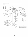
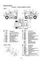
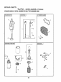
917.250490
MODEL
OWNER'S
MANUAL
Assembmy
Operation
®Customer Responsibilities
®Service and Adjustments
®Repair Parts
CAUTION:
Read and follow
all safety rules and instructions
before operating
this equipment.
FOR CONSUMER ASSISTANCE HOT LINE, CALL THIS TOLL FREE NUMBER: 1-800-659-5917
=__==
illilllllllllllllllllllllllllllINNIHI
IIH
SAFETY
Practices RULES
for Ride-On
Safe Operation
Mowers
IMPORTANT:
THiS CUTTING MACHINE IS CAPABLE OFAMPUTATING
HANDS AND FEET AND THROWING OBJECTS+
FAILURE TO OBSERVE THE FOLLOWING SAFETY INSTRUCTIONS
COULD RESULT IN SERIOUS iNJURY OR DEATH+
I.
•
•
•
•
•
°
=
°
•
•
•
•
•
•
III.
GENERAL OPERATION
Read, understand, and follow ati instructionstn the manual
and on the machine before starting+
Only allow responsible adults, who are famtUar with the
instructions,to operate the machine++
Clear the area of objects such as rocks, toys, wire, etc+,
which could be picked up and thrown by the blade+
Be sure the area is clear of other people before mowing Stop
machine if anyone enters the area+
Never carry passengers
Do not mow in reverse unless absotutely necessary+ Always
look down and behind before and while backing
Be aware of the mower discharge direction and do not point
it at anyone+ Do not operate the mower without either the
entire grass catcher or the guard in place+
Slow down before turning
Never leave a running machine unattended Always turn off
blades, set parking brake, stop engine, and remove keys
before dismounting+
Turn off blades when not mowing+
Stop engine before removing grass catcher or unc!ogging
chute
Mow onty in daylight or good artificial light+
Do not operate the machine while under the influence of
alcohol or drugs
Watch for trafficwhen operating near or crossing roadways+
Use extra care when loading or unloading the machine into
a trailer or truck.
CHILDREN
Tragic accidents can occur if the operator is not alert to the
presence of chiidreno Children are often attracted to the
machine and the mowing activity+ Never assume that
children will remain where you last saw them+
•
Keep children out of the mowing area and under the watchful
care of another responsible adu[t
•
Be alert and tum machine off if children enter the area
•
Before and when backing, look behind and down for small
children
•
Never carry children They may fail off and be seriously
injured or Interfere with safe machine operation
•
Never aflow children to operate the machine
•
Use extra care when approaching blind corners shrubs,
trees, or other objects that may obscure vision
IV. SERVICE
•
Use extra care inhandting gasoline and other fuels They are
flammable and vapors are explosive
Use only an approved container
Never remove gas cap or add fuel with the engine
running Allow engine to cool before refueling Do not
smoke
Never refuel the machine indoors+
Never store the machine or fuel container inside where
there is an open flame, such as a water heater.
•
Never pJn a machine inside a closed area+
°
Keep nuts and bolts, especially blade attachment bolts, tight
and keep equipment in good condition,
°
Never tamper with safety devices, Check their proper
operation regularly+
•
Keep machine free of grass, leaves, or other debris build-up.
Clean oil or fuel spillage. Allow machine to cool before
storing.
•
Stop and inspect the equipment if you strike an object
Repair, if necessary, before restart+ng+
•
Never make adjustments or repairs with the engine running.
•
Grass catcher componentsare subject towear, damage, and
deterioration, which could expose moving parts or allow
objects to be thrown. Frequently check components and
replace with manufacturer's recommended parts, when necessary
•
Mower blades are sharp and can cut+ Wrap the blade(s) or
wear gloves, and use extra caution when servicing them
•
Check brake operation frequently. Adjust and service as
required
i!. SLOPE OPERATION
Slopes are a major factor related to loss-of-control
and
tipover accidents, which can result in severe injury or death
All slopes require extra caution+ If you cannot back up the
slope or if you feel uneasy on it, do not mow it
DO:
•
Mow up and down slopes, not across+
•
Remove obstacles such as rocks, tree limbs, etc+
•
Watch for holes, ruts, or bumps
Uneven terrain could
overturn the machine Tall grass can hide obstacles+
•
Use stow speed+ Choose a tow gear so that you wilt not have
to stop or shift while on the slope+
•
Follow the manufacturer's
recommendations for wheel
weights or counterweights to improve stability
•
Use extra care with grass catchers or other attachments+
These can change the stability of the machine
•
Keep all movement on the slopes slowand gradual Do not
make sudden changes in speed or direction+
•
Avoid starting or stopping on a slope if tires lose traction,
disengage the blades and proceed slowly straight down the
slope
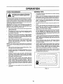
Look fOr this symb01t0P0int
out im-'"
CAUTION!l!
ALERT!t!It means
YOUR
portant safetyBECOME
precautions.
SAFETY IS INVOLVED.
,,,,,,,,mll
DO NOT:
•
Do not turnon slopes unless necessary, and then, turn slowly
and gradually downhill, if possible+
=
Do not mow near drop.offs, ditches, or embankments The
mower could suddenly turn over if a wheel is over the edge
of a cliff or ditch, or if an edge caves in.
•
Do not mow on wet grass+ Reduced traction could cause
sliding+
•
Do not tryto stabilize the machine by putting your foot on the
ground
•
Do not use grass catcher on steep slopes
i
_
wire and placewirewhereit cannot contact
spark plug in order to prevent accidental
starting
setting
up, transporting,
CAUTION:when
Always
disconnect
spark plug
adjust!ng or making,repa irs,
...............
WARNING
&
The engine exhaust from this product contains cliemlcals known to the State of California to cause cancer, birth defects, or other
reproductive harm.
2
PRODUCT SPECIFICATIONS
CONGRATULATIONS
on your purchase of a Sears
Tractor_ It has been designed, engineered and manufactured to give you the best possible dependability and
performance..
Should you experience any problem you cannot easily
remedy, please contact your nearest Sears Authorized
Service Center/Department Department. We have competent, well-trained technicians and the proper toots to
service or repair this tractor..
Please read and retain this manual° The instructions will
enable you to assemble and maintain your tractor properly.
Always observe the "SAFETY RULES",
MODEL
NUMBER
t8.0
GASOLINE CAPACITY
AND TYPE:
3°5 GALLONS
UNLEADED REGULAR
OIL TYPE (API-SF!SG):
SAE 30 (above 32°F)
SAE 5W-30 (below 32°F)
OIL CAPACITY:
Wi FILTER:
4,0 P[NTS
WIO FILTER: 3 5 PINTS
SPARK PLUG:
(GAP: .,025")
CHAMPION RV17YC
VALVE CLEARANCE:
INTAKE:
EXHAUST:
GROUND SPEED (MPH):
FORWARD:
REVERSE:
TIRE PRESSURE:
FRONT:
REAR:
CHARGING SYSTEM:
t5 AMPS @ 3600 RPM
BLADE BOLT TORQUE:
30-35 FT_.LBSo
917o250490
SERIAL
NUMBER
DATEOFPURCHASE
THE MODEL AND SERIAL NUMBERS WILL BE FOUND
ON A PLATE UNDER THE SEAT,
"YOU SHOULD RECORD BOTH SERIAL NUMBER AND
DATE OF PURCHASE
AND KEEP IN A SAFE PLACE
FOR FUTURE REFERENCE.
MAINTENANCE
AGREEMENT
RESPONSiBILiTiES
•
Read and observe
°
Followa regular schedule
using you r tractor.
°
Fo!low the instructions under"Customer
Responsibilities" and "Storage" sections of this owner's manual.
0- 5_6
0-2,5
14 PSI
t0 PSi
In the state of California the above is required by taw
(Section 4442 of the California Public Resources Code).
Other states may have similar faws_ Federal laws apptyon
federal lands. A spark arrester for the muffler is available
through your nearest Sears Authorized Service Center/
Department (See REPAIR PARTS section ofth[s manual)..
the safety rules.
in maintaining,
..003" - ..006"
..013" - ,016"
WARNING: This tractor is equipped with an internal
combustion engine and should not be used on or near any
unimproved forest-covered, brush-covered or grass-covered land unless the engine's exhaust system is equipped
with a spark arrestor meeting applicable Iocai or state laws
(if any)_ Ifa spark arrester is used, it should be maintained
in effective working order by the operator.
A Sears Maintenance
Agreement is available on this product. Contact your nearest Sears store for details,
CUSTOMER
HORSEPOWER:
caring for and
LIMITED TWO YEAR WARRANTY ON CRAFTSMAN
RIDING EQUIPMENT
For two (2) years from the date of purchase, if this Craftsman Riding Equipment is maintained, lubricated and tuned up according
to the instructions in the owner's manual, Sears will repair or replace, free of charge, any parts found to be defective in material
or workmanship°
This Warranty does not cover:
•
•
o
•
Expendable items which become worn dudng normal use, such as blades, spark plugs, air cleaners, belts, etc_
Tire replacement or repair caused by punctures from outside objects,such as nails, thorns, stumps, or glass_
Repairs necessary because of operator abuse, negligence, improper storage or accident or the failure to maintain the
equipment according to the instnJctionscontained in the owner's manual.
Riding equipment used for commercial or rental purposes..
LIMITED 90 DAY WARRANTY ON BATTERY
For ninety (90) days from date of purchase, if any battery included with this riding equipment proves defective in material or
workmanship and our testing determines the battery will not hold a charge, Sears will replace the battery at no charge.
iN-HOME WARRANTY SERVICE ON YOUR CRAFTSMAN RIDING EQUIPMENT IS AVAILABLE AT NO-CHARGE FOR 30
DAYS FROM THE DATE OF PURCHASE. PLEASE CONTACT YOUR NEAREST SERVICE CENTER,_ AFTER 30 DAYS
FROM THE DATE OF PURCHASE, WARRANTY SERVICE IS AVAILABLE BY TAKING YOUR CRAFTSMAN RIDING EQUIPMENT TO YOUR NEAREST SEARS SERVICE CENTER. (IN-HOME WARRANTY SERVICE WILL STILL BE AVAILABLE
AFTER 30 DAYS FROM THE DATE OF PURCHASE BUT A STANDARD TRtP CHARGE WILL APPLY°) THIS WARRANTY
APPLIES ONLY WHILE THIS PRODUCT IS IN THE UNITED STATES..
This Warranty gives you specific legal rights, and you may also have other rightswhich may vary from state to state.
SEARS,
ROEBUCK
AND CO,, D/817 WA, HOFFMAN
3
ESTATES,
IL 60179
llllill
iiiiii
11111111
ii
ii
.,,,,,=...,
i
llUlllll
Jl ii
ii ii
iiiii
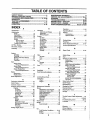
FABLE OF CONTENTS
I
PRODUCT
RULES
............................................................
S PEC|FICA11ONS
2
......................................
UlgUllll_
UI
IIII
IIIL H 3 1
UlIIJ!
SCHEDULE
.....................................
.....
17
Operation
11-16
Operating Mower +..................................... 14
Options:
Accessories ...........................................
5
Spark Arrester .................................
3,40
...............................................
E
A
.!..................
UI
SERVICE AND ADJUSTMENTS
...........................
21-27
STORAGE ...................................................................
2B
TROUBLESHOOTING
...........................................
29-30
REPAIR PARTS - TRACTOR ................................
32-47
REPAIR PARTS - ENGINE ....................................
51-60
PARTS ORDERING/SERVICE
............... BACK COVER
3
CUSTOMER
RESPONSIBILITIES
.....................
3, 17-20
WARRANTY
....................................
,.............................
3
TRACTOR ACCESSORIES
..........................................
5
ASSEMBLY
.............................................................
7-10
OPERATION
..........................................................
11-16
INDEX
II
MAINTENANCE
......................................................
...................................
Electrical:
Accessories .................................................. 5
interlocks and Relays ...........................
26
Adjustments:
Schematic .........................................31
Brake .................................................... 23
Wiring Diagram ...................................32
Carburetor ......................................... 27
Engine:
Clutch Pulley ..................................................
23
Air Filter .............................................. 19
Gauge Wheels ....................................14
Air Screen ...............................................
I9
Mower
Front+To-Back ...................................
22
Cooling Fins .............................................
20
Oil Change ......................................... i9
Side+To-Side
21
OIlLevel .....................................................
15
Throttle Control Cable ........................27
OilType .................................................19
Air Filter, Engine ...................................................
20
Preparation ........................................
14
Air Screen, Engine .........................................
20
Repair Parts ...................................
5I-60
Assembly ....................................................7-10
Stading ...................................................
15
Storage
28
P
Parking Brake ........................................... 12
Pads Bag ...................................................... 6
Pads, FleptacementlRepair
............. 31+47
Product Specifications
3
................................
SAFETY
R
Repair Parts ......................................... 31-47
B
S
H
Headlights .......................................................
26
Hood Removalllnstatlation .......................
26
L
Leveling Mower Deck ............................ 21
Lubrication:
Chart
17
Engine ......................................................
19
......................................................
M
..................................................
T
.....................................
Maintenance Schedule .......................... 17
Mower:
Adjustment, Front-to-Back ..................
22
Adjustment, Side+tooSide .............. 21
BIade Replacement .........................18
Blade Sharpening
18
Cutting Height ................................ 13
Installation
21
Operation .............................................
14
Removal ............................................21
Mowing Tips .................................................16
Muffler ...................................................................
20
Spark Arrester ...........................
3,40
................................................
Carburetor Adjustment ............................ 27
Clutch Pulley ............................................23
Controls, Tractor ......................................12
Customer Responsibilities .................!7-20
Engine:
Air Filter ........................................... 20
Air Screen ....................................... 19
Cooling Fins .................................. 20
Engine Oil .....................................
t5,19
Fuel Filter ...................................... 20
Spark Plug(s) ...........................
20
Tractor;
Battery .............................................. 18
Blade ...................................................18
Lubrication Chart ......................... 17
Maintenance Schedule ............. 17
Tire Care .....................................
8,18,25
Transaxle ........................................ t9
Cutting Height, Mower ............................. 13
Safety Rules ........................................................
2
Seat ....................................................................8
Service and Adjustments ................
21-27
Carburetor ................................................
27
Clutch Pulley ........................................23
Fuse
26
Hood Remova}!Instaltation ............ 26
Motion Drive Belt
Removal]Replacement ..............24
Mower Drive Belt
Remova!/Reptacement ...............
22
Mower Blade Drive Belt
Removal/Replacement .............23
Mower Adjustment
Front+to-Back ................................ 22
Side-to-Side ................................ 21
Mower Removal/Installation ............21
Tire Care ........................................8,25
Slope Guide Sheet ................................. 63
Spark Plug(s) ........................................... 20
Specifications ................................................ 3
Starting the Engine .......................................
t5
Steering Wheel ....................................... 7,24
Stopping the Tractor ...................................13
Storage ...........................................................28
O
Oil:
Cold Weather Conditions ......... 15,19
Engine .....................................................19
Storage ............................................. 28
4
Throttle Control Cable Adjustment ....... 27
8,18,25
Troubleshooting Chart ............................
29-30
Ttansaxle ........................................................19
...........................................................
C
F
Filter:
Air Filter.................................................20
Fuel .............................................................
20
Oil .......................................................... 20
Fuel:
Storage ...............................................
28
Type ...........................................................
15
Fuse ...............................................................26
T_es
Battery:
Charging ..................................................8
Cleaning ................................................20
Starling with Weak Battery .................
25
Storage ................................................. 27
Terminals ............................................ 18
Belt:
Motion Drive
Removal!Replacement ...............
24
Mower Drive
Removal/Replacement .............22
Mower Blade Drive
Removal/Replacement ................
23
Blade:
Sharpening ..........................................18
Replacement ..........................................
t8
Brake Adjustment ..........................................
23
W
Warranty .............................................................3
Wtdng Diagram ..........................................
32
Widng Schematic ........................................
31
ACCESSORME$ A
ATTACH
ENTS
These accessories and attachments were available through most Sears retail outlets and service centers when the tractor was purchased,
Most Sears stores can order these items for you when you provide the model number of your tractor,,
ENGINE
SPARK PLUG
MAINTENANCE
GAS CAN
ENGINEOIL
FUEL STABILIZER
AIR FILTER
BLADES
BELTS
PERFORMANCE
Sears offers a wide variety of attachments that fit your tractor., Many of these are Iisted below with brief explanations of how they can help
you, This list was current at the time of pubtication; however, it may change in future years - more attachments may be added, changes
may be made in lhese attachments, or some may no longer be available or fit your model Contact your nearest Sears store for the
accessories and attachments that are available for your tractor,
Most of these attachments do not require additional hitches or conversion kits (those that do are indicated) and are designed for easy
attaching and detaching.
AERATOR promotes deep root growth for a healthy lawn.. Tapered
2_54nch steel spikes mounted on lO-inch diameter discs puncture
holes in soil at close intervals to let moisture soak in Steel weight tray
for increased penetrationBUMPER
protects front end of tractor from damage_
CARTS make hauling easy. Variety of sizes available, plus accessories such as side panel kits, too[ caddy, cart cover, protective mat and
dolly._
CORING AERATOR takes small plugs out of soil to allow moisture
and nutdentsto reachgrass roots 36-inch swath 24 hardened steel
coring tips° 150 lb. capacity weight tray.
DISC HARROW has 2 gangs of 4 steel blades that angle from 10 to
20 degrees, 40 inches wide. Can hook 2 units in tandem.. (Requires
sleeve hitch,)
DOZER BLADE removes snow; grades
inches wide, 17 inches high, clears 44-inch
lift control lever for operator ease Spring
uneven pavement; built-in float for blade
Reversible, replaceable scraper bar. (Use
weights andtor rear drawbar weight)
dirt, sand and gravel. 48
path when angled. Master
trip for snow removal on
to follow ground contour.
with tire chains and wheel
EASY OIL DRAIN VALVE makes oil changes easier, faster,
FRONT NOSE ROLLER canters in front of mower deck to reduce
chances of "scalping" on uneven terrain..
GANG HITCH lets you tow 2 or 3 pul!-behind attachments
at
once, such as sweepers, dethatchers, aerators (not for use with
rollers, carts or other heavy attachments).
MULCH RAKE/DETHATCHER
loosens soil and flips thatch and
matted leaves to lawn surface for easy pickup Twenty spring tine
teeth, Useful to prepare bare areas for seeding, Available for front or
rear mounting. HIGH PERFORMANCE
REEL-ACTION
SPRING
TINE DETHATCHER covers 36-inch wide path and tosses thatch into
large hopper. Mounts behind tractor.
PLOW turns soil 6 inches deep, cuts 10-fnch furrow.. Crank adjustment controls depth, 3-position yoke setswidth, Heavy steel landside
for straight furrowing. (Requires sleeve hitch.)
RAMP TOPS AND FEET let you load and unload tractor
pickup truck. Use with 2 x 8 or 2 x 10 lumber.
from a
REAR GRADER BLADE is 42 Inches wide and operated from ddver's
seat. Reversible steel blade can be angled at 30 degrees for grading
Reverses for pushing snow backwards,
(Requires sleeve hitch)
ROLLER for smootherlawn
surface, 36-Inch wide, 18-inch diameter
water-tight drum holds up to 390 Ibs. of weight.
Rounded edges
prevent harm to turf, Adjustable scraper automatically cleans drum
SLEEVE CULTIVATOR
is 43 inches wide. Prepares ground for
seeding, helps weed control, Steel frame holds 5 adjustable sweeps,
Adjusts vertically, hodzontally_ (Requires sleeve hitch ) Optional
accessory:
steel furrow opener for wider openings for potatoes,
corn, and other deep-seeded crops°
SLEEVE HITCH for use with master lift system_
uncouples..
Single pin couples/
SNOWTHROWER
has 42-1nch swath.
Drum-type auger handles
powdery and weVheavy snow. Mountseasilywithsimpteptnarrangemont, Discharge chute adjusts from tractor seat. 6-inch diameter
spout discharges snow 10 to 50 feet, Lift controlled at tractor seat.
(Use with chains and wheel weights and/or rear drawbar weight.)
SPRAYERS use 12-volt DC electric motor that connects to the tractor
battery or other 12-volt source
includes booms for automatic
spraying and hand held wand for spot spraying.. Wand has adjustable
spray pattern. For applying herbicides, insecticides, fungicides and
liquid fertiltzers_
SPREADER/SEEDERS
make seeding, fertilizing, and weed killing
easy Broadcast spreaders are also useful for granular de-icers and
sand.
SWEEPERS
let you collect grass clippings
and leaves
TILLER has 8 hp engine to prepare seed beds, cultivate, and compost
garden residue. Chain.drive transmission.
Six 11-inch diameter one
piece heat-treated steel tines, Tills 30-inch path. (Requires sleeve
hitch.) Oruse 5 hp tow-behind TILLER with 36-inch swath to prepare
seed beds, cultivate and compost garden residue. Tiller has its own
built-in lift and depth control system and does NOT require a sleeve
hitch. Fits any lawn, yard or garden tractor. Simply hook up to the
tractor drawbar end got Optional accessories for 5 hp tiller convert
unit for dethatching, aerating, hilling ..without toots.
TIRE CHAINS are heavy duty; closely spaced extra-large
give smooth ride, outstanding tractiom
cross links
TRACTOR CAB has heavy duty vinyl fabric over tubular steel trame,
ABS plastic top; clear plastic windshield oilers 360 degree visibility.
Hinged metal doors with catch.
Keeps operator warm and dry,
Remove vinyl sides and windshields
for use as sun protector in
summer.
Optional accessories
include:
tintedltempered solid
safety glass windshield with hand operated wiper;, 12-volt amber
caution light for mounting on cab top
VACS for powerful collection of heavy grass clippings and leaves
Optional wand attachment to pick up debris in hard-to-reach places
VACICHIPPER includes a chipper-shredder,
WEIGHT BRACKET for drawbar for snow removal applications, Can
be mounted on front of tractor for plowing applications,
Uses (1) 55
Ib weightr
WHEEL WEIGHTS for rear wheels provide needed traction for snow
removal or dozing heavy materials.
CONTENTS
iii
iiii
iiiiWllllJlujll
OF HARDWARE
j
PACK
iiiii i i i i
lUlIII'II[
Parts Bag contents shown full size
I
II
III
Parts packed separately
ii
I
IIIIW['I
I
i/
in carton
,,,,,,,, ,,,,,,,,,
,,,
(1) Shoulder Bolt 5116-18
Seat
Video
Cassette
Steering
Wheel
O
(1) Washer 17/32 x 1-3/16 x 12 Gauge
i
ii
I
..................
:
t
e
t
i
i
I
I
I
I
,lllllllWiiiiiiiii
Manual
ii
Parts Bag
..................................
Parts bag contents
iiii
not shown full size
,,,
(3) Retainer Springs (double toop)
_/.1-_
(2) Shoulder /
Bolts
_(2)
(4) Retainer Springs (single loop)
iiiiiiiiiiii1'
(2) Hex Bolts 1/4-20 x3/4
IILJI
iii
i
j
_
"x
i&-_'l
@
_.g//.,/_2)Gauge
Wheels
, ,,,,, ,,
.............
x(2)7t8
Washers
x 14 Gauge
3/8
Q
(2)Centerlock Nuts
Front Link Assemblies
_
i
@
O
Wheel
teering
Insert
(2) Keys
(2) Hex Nuts 1/4-20
(2) Washers 9132 x 518
x 16 Gauge
(2) Lock Washers
1/4
Steering
Sleeve
Slope Sheet
iiilUUllli
6
i, i1,1111,
BLY
Your new tractor has been assembled at the factory with exception of those parts left unassembted for shipping purposes,.
To ensure safe and proper operation of you r tractor all parts and hardware you assemble must be tightened securely,. Use
the correct tools as necessary to insure proper tightness_
TOOLS REQUDRED FOR ASSEMBLY
STEERING WHEEL
|NSERT
A socket wrench set will make assembly easier.. Standard
wrench sizes are listed°
(2) 7/16" wrenches
(1) Tire pressure gauge
(1) 9/16" wrench
(1) Utility knife
(1) 1/2" wrench
(1) 3/4" socket w/drive ratchet
When right or left hand is mentioned in this manual, it
means when you are in the operating position (seated
behind the steering wheel).
TO REMOVE
TRACTOR
FROM CAR-
TON
UNPACK
CARTON
o
Remove all accessible loose parts and parts cartons
from carton (See page 6),
-
Cut, from top to bottom, along lines on all four corners
of carton, and lay panels flat.
=
Remove mower and packing materials.
=
Check for any additiona! loose parts or cartons and
remove°
Y
1
/
/
!
_/ t
t/!
1
t
/
BEFORE ROLLING TRACTOR OFF SKID
ATTACH STEERING
,
°
•
°
°
•
FIG, 1
WHEEL (See Fig. 1)
Remove hex bolt, lock washer and large flat washer
from steering shaft.
Positionfront wheels ofthe tractorso they are pointing
straight forward.
TO ROLL TRACTOR
Slide the steering sleeve over the steering shaft.
Position steering wheel so cross bars are horizontal
(left to right) andslide onto steering wheel adapter.
Secure steering wheel to steering shaft with hex bott,
lock washer and large flat washer previouslyremoved.
Tighten securely°
o
°
Raise attachment lift lever to its highest position.
Retease parking brake by depressing clutch/brake
pedal.
.
Place freewheel control in freewheeling position to
disengage transmission (See "TO TRANSPORT" in
Operation section of this manual),
Roll tractor backwards off skid..
•
Snap steedng wheel insert into center of steering
wheel
o Remove protective plastic from tractor hood and grill.
IMPORTANT; CHECK FOR AND REMOVE ANY STAPLES
IN SKID THAT MAY PUNCTURE TIRES WHERE TRACTOR
IS TO ROLL OFF SKIDo
7
OFF SKID (See Fig. 7)
MBLY
illllllllllli iiiiill,V
ullllllUlll
i i
HOW TO SET UP YOUR TRACTOR
CONNECT
BATTERY
......................
!,,! !,! ............
I
!Will
Adjust seat before tightening adjustment knob°
i
I
IIIII
III
II II I I
,
°
Assemble adjustment knob and flat washer loosely
Do not tighten.
°
Tighten shoulder bolt securely.
Positive terminal must be connected
first to prevent sparking from accidental grounding.
,
Lower seat into operating position and sit on seat_
°
Slide seat until a comfortable position isreached which
allows you to press clutch/brake pedal all the way
down.
°
Get off seat without moving its adjusted position.
°
Raise seat and tighten adjustment knob securely.
Lift hood to raised position.
°
Open terminal access doors, remove terminal protective caps and discard.
°
If this battery is put into service after month and year
indicated on label (label located between terminals)
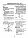
charge battery for minimum of one hour at 6-10 ampso
SEAT
First connect RED battery cable to positive (+) battery
terminal with hex bolt, flat washer, lock washer and hex
nut as shown° Tighten securely_
SEAT PAN
SHOULDER
BOLT
•
Connect BLACK grounding cable to negative (-) battery terminal with remaining hex bolt, flat washer, lock
washer and hex nut. Tighten securely.
•
Close terminal access doors_
Use terminal access doors for:
°
Remove cardboard packing on seat pan.
Place seat on seat pan and assemble shoulder bolt.
nals. Before connecting battery, reCAUTION:
move
metalDo bracelets,
not short battery
wristwatch
termibands, rings, etc.
•
°
_ULL
INSTALL SEAT (See Fig. 3)
(See Fig. 2)
i,
ii .................
Inspection for secure connections (to tighten hardware),
•
FLAT
WASHER
Inspection for' corrosion.
•
•
Testing battery.
Jumping (if required).
°
Periodic charging.
HEX NUT
DISCARD
TERMINAL
PROTECTIVE
CAPS
ADJUSTMENT
KNOB
FIG. 3
LOCK
WASHER
CHECK TIRE PRESSURE
FLAT
WASHER
The tires on your tractor were overinflated at the factory for
shipping purposes. Correct tire pressure is important for
best cutting performance.
HEX
•
TERMINAL
ACCESS
DOOR
Reduce tire pressure to PSi shown in "PRODUCT
SPECIFICATIONS" on page 3 of this manual.
CHECK BRAKE SYSTEM
_'"
.-"
After you learn how to operate your tractor, check to see
that the brake is properly adjusted. See "TO ADJUST
BRAKE" in the Service and Adjustments section of this
manual.
POSITIVE
(RED)
CABLE
i
NEGATIVE
(BLACK)
CABLE
VENT HOLE
(KEEP CLEAN)
FIG. 2
8
(See
o
Connect anti-sway bar to chassis bracket under left
footrest and retain with double loop retainer spring,,
Be sure tractor is on level surface and mower suspension
arms are raised with attachment lift control. Engage parking brake.
•
Cut and remove tie down securing anti-sway bar.
Swing anti-sway bar to left side of mower deck.
o Slide mower under tractor with discharge guard to right
side of tractor°
°
Turn height adjustment knob clockwise to remove
slack from mower suspension,,
=
Raise deck to highest position_
=
Assembtegaugewheelsas shown using long shoulder
bolts, 3/8 washers, and 3/8-16 center Iocknuts, Tighten
securely°
°
Adjustgaugewheelsbeforeoperating
mowerasshown
in the Operation section of this manual.
INSTALL MOWER
Figs, 4 and 5)
AND DRIVE BELT
IMPORTANT: CHECK BELT FOR PROPER ROUTING IN
ALL MOWER PULLEY GROOVES, INSTALL BELT INTO
ELECTRIC CLUTCH PULLEY GROOVE.
°
°
o
°
-
CHECK DECK LEVELNESS
For best cutting resufts, mower housing should be properly
leveted, See 'q'O LEVEL MOWER HOUSING" in the
Service and Adjustments section of this manual.
Install one front link in top hole of the L.H. front mower
bracket and LoHofront suspension bracket. Retain with
two single loop retainer springs as shown,,
Installsecond front linkin RoHofrontsuspension bracket
and retain with single loop retainer spring as shown,
CHECK
BELTS
Slide right side of mower deck back and install link in
top hole of R,,H_front mower bracket Retain with single
loop retainer spring as shown.
Place the suspension arms on inward pointing deck
pins° If necessary, rock and raise front of mower to
align deck pins with the holes in suspension arms.
Retain with double loop retainer springs.
L.H.
WH! GAUGE
SUSPENSION
ARMS
DOUBLELOOP
RETAINER SPRING
(Inwardpointing
deckpin_
DOUBLE LOOP
RETAINER SPRING
POSITION
OF ALL
See the figures that are shown for replacing motion, mower
drive, and mower blade drive belts in the Service and
AdjustmentssectionofthismanuaL
Verifythatthe beltsare
routed correctly_
Turn height adjustment knob counterclOckwise until it
stops,
Lower mower linkage with attachment lift control
CHASSIS
FOR PROPER
FRONT
LINKS
FRONT
SUSPENSION
BRACKETS
ELECTRIC
CLUTCH
PULLEY
_'_"-_,.
SINGLE
LOOP RETAINER
SPRINGS
SHOULDER
BOLT
GAUGE
WHEEL
FRONT MOWER
BRACKET
318_6
CENTER
LOCKNUT
ANTI-SWAY
BAR
3/BWASHER
IDLER
PULLEY
DISCH,
GUARD
FIG. 4
9
,/CHECKLIST
BEFORE YOU OPERATE AND ENJOY YOUR NEW
TRACTOR, WE WISH TO ASSURE THAT YOU RECEIVE
THE BEST PERFORMANCE AND SA TISFACTtON FROM
THIS QUALITY PRODUCT
PLEASE REVIEW THE FOLLOWING CHECKLIST:
4" AI! assembly instructions have been compfeted_
,/
No remaining loose parts in carton.
,/
Battery is properly prepared and charged. (Minimum
1 hour at 6 amps).
Seat is adjusted comfortably and tightened securely.
/
J"
All tires are properly inflated. (For shipping purposes,
the tires were overinflated at the factory).
,/
Be sure mower' deck is properly leveled side-to-side/
front-to-rear for best cutting results_ (Tires must be
properly inflated for Leveling).
Check mower and ddve belts. Be sure they are routed
properly around pulleys and inside all belt keepers.
,/
/'
Checkwidng. See that all connections are still secure
and wires are properly c[amped_
,/
Before driving tractor, be sure freewheel control is in
drive position.
WHILE LEARNING HOW TO USE YOUR TRACTOR, PAY
EXTRA ATTENTION TO THE FOLLOWING IMPORTANT
ITEMS:
,/
Engine oi_is at proper' level.
,t
Fuel tank is filled with fresh, clean, regular unleaded
gasoline.
Become familiar with all controls - their location and
function. Operate them before you start the engine.
,/
,/
,/
Be sure brake system is in safe operating condition.
It is important to purge the transmission before operating your tractor for'the first time. Follow proper starting
and transmissionpurging instructions(See'_O START
ENGINE and "PURGE TRANSMISSION in Operation section of this manual).
10
OPERATmON
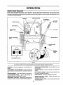
These symbols may appear on your tractor or in literature supplied with the product,. Learn and understand they meaning..
BATTERY
CAUTION OR
WARNING
REVERSE
FORWARD
FAST
SLOW
ENGINE ON
ENGINE OFF
OIL PRESSURE
CLUTCH
LIGHTS ON
LIGHTS OFF
FUEL
CHOKE
MOWER HEIGHT
DIFFERENTIAL
LOCK
PARKING BRAKE
LOCKED
UNLOCKED
L
REVERSE
MOWER LIFT
NEUTRAL
ATTACHMENT
CLUTCH ENGAGED
HIGH
LOW
ATTACHMENT
CLUTCH DISENGAGED
PARKING BRAKE
IGNITION
HYDROSTATIC FREE WHEEL
(Hydro Models only)
DANGER, KEEP HANDS AND FEET AWAY
11
.........
,...............
,,,,,
,,,,
.............................
i i
i
iiiiiii
ii iiiiiiiiiii
ii
.. i
ii,
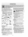
KNOW YOUR TRACTOR
READ THIS OWNER'S
MANUAL AND SAFETY RULES BEFORE OPERATING
YOUR TRACTOR.
Compare the illustrations with yourtractor to familiarize yourselfwith the locationof variouscontrols and adjustments°Save
this manual for future reference.
THROTTLE CONTROL
AMMETER
ATTACHMENT
CLUTCH SWITCH
"....
CHOKE CONTROL
%
, LIFT LEVER
PLUNGER
LIGHT SWITCH
CLUTCH/BRAKE
PEDAL
MFT LEVER
HEIGHT ADJUSTMENT
KNOB
IGNITION SWITCH
PARKING BRAKE
LEVER
MOTION
CONTROL
LEVER
SPEEDS:
/
FREE WHEEL CONTROL
FIG. 5
Our tractors conform to the safety standards of the American National Standards Institute,.
AMMETER - indicates charging (+) or discharging (-) of
battery,
HEIGHTADJUSTMENT KNOB- Used to adjust the mower
cutting height°
ATTACHMENT CLUTCH SWITCH - Used to engage the
mower blades or other attachments mounted to your tractor.
IGNITION SWITCH - Used for starting and stopping the
engirre.
LIFT LEVER PLUNGER =Used to release attachment lift
lever when changing its position.
CHOKE CONTROL - Used when starting a cold engine.
LIGHT SWITCH _Turns the headlights on and off,,
CLUTCH/BRAKE PEDAL - Used for declutching and
braking the tractor and starting the engine.
MOTION CONTROL LEVER - Selects the speed and
direction of the tractor'.
FREEWHEEL CONTROL _ Disengages transmission for
pushing or slowly towing the tractor with the engine off°
PARKING BRAKE LEVER - Locksclutch/brake pedal irrto
the brake position.
12
OPERATION
The operation of any tractor can result in foreign objects thrown into the eyes, which can result
in severe eye damage. Always wear safety glasses or eye shields while operating your tractor
or performing any adjustments or repairs. We recommend a wide vision safety mask over the
spectacles or standard safety glasses,
i
ii H
,I
I
_lu I
'
I,
II
'"'J_J,
I'
I,
'll'
I,.I
II I
HOW TO USE YOUR TRACTOR
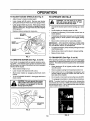
TO SET PARKING
I,I,
:
NOTE: Under certain conditions when tractor is standing
idle with the engine running, hot engine exhaust gases may
cause "browning" of grass_ To eliminate this possibility,
always stop engine when stopping tractor on grass areas,,
BRAKE (See Fig. 6)
Yourtractor isequipped with an operatorpresence sensing
switch. When engine is running, any attempt by the
operator to leave the seat without first setting the parking
brake will shut off the engine,,
= Depress clutch/brake pedal into full "BRAKE" position
and hold.
= Place parking brake lever in"ENGAGED" position and
release pressure from clutch/brake pedal. Pedalshould
remain in' BRAKE" position. Make sure parking brake
wil! hold tractor secure.
PUSH IN TO
THROTTLE
"DISENGAGE"
CONTROL LEVER
,I,
....
......
cAuTION:
AlwaYs stop tractor Completely, as described above, before leaving the operator's position; to empty
grass catcher, etc.
TO USE CHOKE CONTROL
(See Fig. 6)
Use choke control whenever you are starting a cold engine.
Do not use to start a warm engine,
° To engage choke control, pull knob out, Slowly push
knob in to disengage,,
ATTACHMENT CLUTCH
SWITCH PULL OUT TO
TO USE THROTTLE
CHOKE
CONTROL
(See Fig. 6)
A{ways operate engine at full throttle.
•
Operating engine at less than full throttle reduces the
battery chargmg rate.
° Full throttle offers the best bagging and mower performance°
CONTROL
CLUTCH/BRAKE
PEDAL "BRAK
POSITION
TO MOVE FORWARD
(See Fig. 6)
IGNITION
AND
BACKWARD
The direction and speed of movement is controlled by the
motion control lever.
MOTION
CONTROL
LEVER
"DRIVE"
POSITION
HEIGHT
ADJUSTMENT
KNOB
"DISENGAGED ....
POSITION
PARKING
BRAKE
ENGAGED"
POSITION
(See Fig. 6)
NOTE; Failure to move throttle control to stow (,_=_)
position and allowing engine to idle before stopping may
cause engine to "backfire"°
•
Turn ignition key to "OFF" position and remove key.
Always remove key when leaving tractor to prevent
unauthorized use°
Never use choke to stop engine,
°
Release parking brake and clutch/brake pedal.
°
Slowly move motion control lever to desired position.
HEIGHT
The cuttingheight is controlledby turningthe height adjustment knob in desired direction,
Turn knob clockwise (('_) to raise cutting height,,
•
Turn knob counterclockwise (IF-,)to
lower cutting
height,,
The cutting height range is approximately 1-1/4" to 4-1/4"o
The heights are measured from the ground to the blade tip
with the engine not running, These heights are approximate and may vary depending upon soi! conditions, height
of grass and types of grass being mowed°
° The average lawn should be cut to approximately 2-1/2
inches during the cool season and to over 3 inches
during hot months, For healthier and better looking
lawns, mow often and after moderate growth.
°
For best cutting performance, grass over 6 inches in
height should be mowed twice. Make the first cut
relatively high; the second to desired heighL
MOWER BLADES •
Move attachment clutch switch to "DISENGAGED"
position°
GROUND DRIVE °
Depress clutch/brake pedal into full "BRAKE" position,,
°
Move motion control lever to neutral IN) position°
IMPORTANT: THE MOTION CONTROL LEVER DOES
NOT RETURN TO NEUTRAL (I'4) POSLT_ONWHEN THE
CLUTCH/BRAKE PEDAL IS DEPRESSED.
ENGINE Move throttle control to slow (-_) position.
.
Start tractor with motion control lever in neutral IN)
position.,
TO ADJUST MOWER CUTTING
(See Fig. 6)
FIG. 6
STOPPING
=
13
.......................
TO ADJUST
•
•
Adjust mower to desired cutting heighL
Lower mower with lift control.. Remove rear retainer
spring and clevis pin which secure each gauge wheel.
Lower gauge wheels to ground° Raise gauge wheels
slightly to align holes in bracket and gauge wheel bar
and insertclevis pins° Gauge wheels should be slightly
off the ground,
-
•
j-
Replace retainer springs into clevis pins.
RETAINER
SPRING
GAUGE
WHEEL
BRACKET
FIG. 7
CAUTION: Do not drive Up or down
hills with slopes greater than 15 ° and
do not drive across any slope.
I
J
J
!
Choose the slowest speed before starting up or down
hills..
•
°
Avoid stopping or changing speed on hills_
If slowing is necessary, move throttle control lever to
s!ower position.
°
If stopping is absolutely necessary, push clutch/brake
pedal quickly to brake position and engage parking
brake.
•
To restart movement, slowly release parkingbrake and
clutch/brake pedal
•
°
Slowly move motion control lever'to slowest setting.
Make all turns slowty,
TO TRANSPORT
MOWER (See Figs. 5 and 6)
o
Start mower blades by engaging attachment clutch
control.
•
TO STOP MOWER BLADES - disengage attachment
clutch contro!..
without either the entire grass catcher,
on mowers so equipped, or the disCAUTIONi Do not operate the mower
charge guard in place.
(See Figs. 5 and 9)
When pushing or towing your tractor, be sure to disengage
transmission by placing freewheel control in freewheeling
position. Free wheel controlis located at the rear drawbar
of tractor..
Your tractor is equipped with an operator'presence sensing switch. Any attempt by the operator to leave the seat
withthe engine running and the attachment clutchengaged
will shut off the engine.
•
Select desired height of cut..
°
Lower mower' with attachment liftcontrol.
.....
,LI_
° Move motion control lever to neutral (N) position°
IMPORTANT: THE MOTION CONTROL LEVER DOES
NOT RETURN TO NEUTRAL (N) POSITION WHEN THE
CLUTCH/BRAKE PEDAL IS DEPRESSED_
GAUGE
WHEEL BAR
j _
,,H J..ll'
•
CLEVIS PIN
TO OPERATE
llll
TO OPERATE ON HILLS
GAUGE WHEELS (See Fig. 7)
•
Raise attachment lift to highest position with attach*
merit Liftcontrol
•
Remove retainer spring from freewheel control rod.
•
Push control rod in to disengage transmission and
reinsert retainer spring into control rod hole now on
back side of the bracket.
•
Do not push or tow tractor at more than two (2) MPH.
°
To reengage transmission, reverse above procedure.
NOTE: To protect hood from damage when transporting
your' tractor on a truck or a trailer, be sure hood is closed
and secured to tractor. Use an appropriate means of tying
hood to tractor (rope, cord, etc_)_
!
DISCHARGE
GUARD
FIG. 8
14
FIG. 9
OPERATION
BEFORE STARTING THE ENGINE
TO START ENGINE (See Fig. 6)
CHECK ENGINE OIL LEVEL (See Fig. 10)
When starting engine for the first time or if engine has run
out of fuel, it willtake extra cranking time to move fuel from
the tank to the engine.
=
The engine in your tractor has been shipped, fromthe
factory, already filled with summer weight oil
o
Check engine oil with tractor on level ground.
°
•
•
•
•
Depress clutch/brake pedal and set parking braker
Place motion control lever in neutral (N) position.
Remove oilfil! cap/dipstickand wipe clean, reinsertthe
dipstick and push it all the way down intothe tube,wait
for a few seconds, remove and read oil level, if
necessary, add oil until "FULU' mark on dipstick is
reached., Do not overfill,,
°
Move attachment clutch to "DISENGAGED" position.
•
Pull choke control out to choke (]XI) position for cold
engine start° For warm engine start do not use choke
control
For cold weather operation you should change oil for
easier starting (See "OIL VISCOSITY CHART" in the
Customer Responsibilities section of this manual)°
°
Move throttle control to midway between fast (,_) and
slow (,¢_) positions,
•
Insert keyinto ignition and turn key clockwise to"START"
position and release key as soon as engine starts, Do
not run starter continuously for more than fifteen
seconds per minute., If engine does not start after
several attempts, move throttle control to fast ('Pe_)
position, wait a few minutes and try again°
.
°
When engine starts, slowly push choke control in.
Move throttle control to fast (._,) position.
•
Allow engine to warm up for a few minutes before
engaging drive or attachments,,
To change engine oil, see the Customer Responsibilities section in this manual,,
ENGINE OIL
FILL CAP/DIPSTICK
\,
IMPORTANT: COLD STARTING FOR HYDRO (BELOW
40 F) - AFTER STARTING ENGINE AND BEFORE
DRIVING, LET TRANSMISSION WARM UP FOR (1)
MINUTE BY PLACING MOTION CONTROL LEVER IN
NEUTRAL AND RELEASING CLUTCHtBRAKE PEDAL.
FIG. 10
NOTE: If at a high altitude (above 3000 feet) or in cold
temperatures (below 32°F), the carburetor fuel mixture
may need to be adjusted for best engine performance. See
"TO ADJUST CARBURETOR" in the Service and Adjustments section of this manual.,
ADD GASOLINE
-
Fill fuel tank. Use fresh, c_ean, regular unleaded
gasoline° (Use of leaded gasoline will increase carbon
and lead oxide deposits and reduce valve life)_
IMPORTANT: WHEN OPERATING IN TEMPERATURES
BELOW 32°F(0°C), USE FRESH, CLEAN WINTER GRADE
GASOLINE TO HELP INSURE GOOD COLD WEATHER
STARTING.
WARNING: Experience indicates that alcohol blended
fuels (called gasohol or using ethanol or methanol) can
attract moisture which leads to separation and formation of
acids during storage_ Acidic gas can damage the fue!
system of an engine while in storage,, To avoid engine
problems, the fuel system should be emptied before storage of 30 days or longer, Drain the gas tank, start the
engine and let it run until the fuel lines and carburetor are
empty. Use fresh fuel next season,, See Storage instructions for additional information.
Never use engine or
carburetor cleaner products in the fuel tank or permanent
damage may occur.,
]
'15
_,_...............
i
ill i
ii,
iillllll
lUl/iJll
i
MOWING TIPS
PURGE TRANSMISSION
freewheel
while
the engine
is runCAUTION: lever
Never
engage
or disengage
ning,
To ensure proper operation and performance, it is recommended that the transmission be purged before operating
tractor for the first time. This procedure will remove any
trapped air' inside the transmission which may have developed during shipping of your tractor.
IMPORTANT: SHOULDYOURTRANSMISSION REQUIRE
REMOVAL FOR SERVICE OR REPLACEMENT, IT
SHOULD BE PURGED AFTER REINSTALLATION
BEFORE OPERATING THE TRACTOR.
•
Place tractor safely on level surface with engine off and
parking brake set.
•
Disengage transmission by placing freewheel control
in freewheeling position (See 'q'O TRANSPORT" in
this section of manual)_
•
Sitting in the tractor seat, start engine° After the engine
is running, move throttle control to slow (,,J_) position.
With motion control lever in neutral (N) position, slowly
disengage clutch/brake pedal
Move motion control lever to full forward position and
hold for five (5) seconds. Move lever to full reverse
position and hold for five (5) seconds. Repeat this
procedure three (3) times.,
•
Tire chains cannot be used when the mower housing
is attached to tractor,.
•
Mower should be properly leveled for' best mowing
performance. See "TO LEVEL MOWER HOUSING" in
the Service arid Adjustments section of this manual
Use the runner on the right hand side of mower' as a
guide_ The blade cuts approximately an inch outside
the runner (See Fig. 8).
The left hand side of mower should be used for trimming o
•
°
•
°
•
NOTE: During this procedure there wil! be no movement of
drive wheels° The air is being removed from hydraulic drive
system.
° Move motion controllever to neutral (N) position. Shutoff engine and set parking brake.
•
Engage transmission by placing freewheel control in
driving position(See "TO TRANSPORT" in this section
of manua!).
° Sitting inthe tractor seat, start engine. Afterthe engine
is running, move throttle control to half (1/2) speed.
With motion controllever'in neutral (N) position,slowly
disengage clutch/brake pedal.
°
Slowly move motion control lever forward, after the
tractor moves approximately five (5) feet, slowly move
motion control lever to reverse position. After the
tractor moves approximately five (5) feet return the
motion controltever tothe neutral (N) position. Repeat
this procedure with the motion control lever three (3)
times.
•
°
Ddve so that clippings are discharged onto the area
that has been cut. Have the cut area to the right of the
tractor'. This will result in a more even distribution of
clippings and more uniform cutting.
When mowing large areas, start by turning to the right
so that clippings will discharge away from shrubs,
fences, driveways, etc. After one or two rounds, mow
in the opposite direction making left hand turns until
finished (See Fig, 11),.
If grass is extremely tall, it should be mowed twice to
reduce load and possible fire hazard from dried clippings. Make first cut relatively high; the second to the
desired height..
•
Do not mow grass when it is wet. Wet grass will plug
mower and Ieave undesirable clumps. Allow grass to
dry before mowing.
•
Always operate eng.!he at full throttle when mowing to
assure better mowing performance and proper' discharge of material. Regulate ground speed by selecting a low enough gear to give the mower cutting
performance as well as the quality of cut desired°
•
When operating attachments, select a ground speed
that will suit the terrain and give best performance of
the attachment being used.
F
Your tractor is now purged and now ready for normal
operation°
FIG. 11
16
CUSTO
MAINTENANCE
SCHEDULE
AS YOU COMPLETE
._REGULAR SERV!CE_ .....
Check Brake Operation
Check"io"i"L00se
T
0
R
Check
_
i_
F'asteners
V #'
i......... J_#' ' .........
i
................
i_
J
j
"
"
LevellRecharge
...............
........
SER'V'ICE
DATES
i _
Chart
Ba!!ery
../__
/__O_
./'__..
=,Check Tire Pressure
Lubrication
IER RESPONSUBILITIE$
.......
]
:_#'7
G##
'i,.'.............
"
v"
......
_
'
Clean Battery and Terminals
Check Transaxle
Cooling
Adjust Blade Belt(s) Tension
Adjust Motion Drive Belt(s) Tension
=
Check Engine Oil Level
_1_
......
Change
Eogi, ;o ,........
N_
v'
"
Cle,an,,,Air
Clean
Air Screen
Filter
G
Inspect
f
!
!
!
_F
=
..
Mufl]ertSparkArrester
1
Replace
N
€lean
Oil Filter (if equipped)
Engine Cooling
V'2
Fins
Replace
Sp.rkPug.....
= ....
Replace
Air Filter Paper Cartridge
.............
Replace
Fuel Filter
......
12 3 4. -
I_
....
i
i
i
!
V' "J I "
,_............. _
.....
V#2
_
Change more often when operaling under a heavy load or tn high ambient temperatures
Service more often when operating In dirty or dusty conditions,
If equipped with ell filter, change oil even] 50 hours
Replace blades more often when mowing In sandy soil
........
5. f! equipped with adjuslable system
6 - Nol required if equipped with maintenance-freebatteq/,
7 - "i'lghlen front axieplvol bolt to35 It -lbs maximum
Do not overtighten
GENERAL RECOMMENDATIONS
LUBRICATION
The warranty on this tractor does not cover items that have
been subjected to operator abuse or negligence,, To
receive full value from the warranty, operator must maintain
tractor as instructed in this manual°
CHART
(_)TIE ROD BALL JOINTS
NDLE ZERK (_)
(_ SPINDLE ZERK -_,
Some adjustments will need to be made periodically to
properly maintain your tractor_
All adjustments in the Service and Adjustments section of
this manual should be checked at least once each season,,
BEAR,N ZER.
"'
FRONT WHEEL (_)
REARING ZERK
@
Once a year you should replace the spark plug, clean
or replace air filter, and check blades and belts for
wear° A new spark plug and clean air filter assure
proper air-fuel mixture and help your engine run better
and last longer°
SECTOR GEAR
TEETH
" ENGINE @
)
BEFORE EACH USE
•
Check engine oil level.
,
o
°
Check brake operation.
Checktire pressure°
Check for loose fasteners.
(_) SPRAY SILICONE LUBRICANT (MOVE BOOTS TO LUBRICATE)
IMPORTANT:
00 NOT OIL OR GREASE THE PIVOT POINTS
WHICH HAVE SPECIAL NYLON BEARINGS,
VISCOUS LUBRICANTS WILL ATTRACT DUST AND DIRT THAT WILL SHORTEN
THE LIFE OF THE SELF-LUBRICATING
BEARINGS.
IF YOU
FEEL THEY MUST BE LUBRICATED,
USE ONLY A DRY. POWDERED GRAPHITE TYPE LUBRICANT
SPARINGLY,
@ GENERAL PURPOSE GREASE
(_) REFER TO CUSTOMER RESPONSIBILITIES
17
"ENGINE"
SECTION
I IIIIII
_J_:
IL II IIIIII
•
...............................
CUSTOMER
..........
ii111111
.
:::::
II
I
I I
ii
IIIII
I
I
I
! llIl1111111
,
III
IIIIIIIIIIIII
_'
,
,
...........................................
TRACTOR
TO SHARPEN
Always observe safety rules when performing any maintenanceo
Care should be taken to keep the blade balanced. An
unbalanced blade willcause excessive vibrationand eventual damage to mower and engine.
BRAKE OPERATION
°
If tractor requires more than six (6) feet stopptng distance
at high speed in highest gear, then brake mustbe adjusted.
(See "TO ADJUST BRAKE" in the Service and Adjustments section of this manual).
•
TIRES
=
•
Maintain proper air pressure in all tires (See "PRODUCT SPECIFICATIONS" on page 3 of this manual),
o
Keep tires free of gasoline, oil, or insect control chemi_
cals which can harm rubber.
°
Avoid stumps, stones, deep ruts, sharp objects and
other hazards that may cause tire damage.
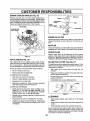
BLADE (See Fig. 13)
The blade can be sharpened with a file or on a grinding
wheel. Do not attempt to sharpen whlie on the mower.
To check blade balance, you will need a 5/8" diameter
steel bolt, pin, or a cone balancer. (When using a cone
balancer, follow the instructions supplied with balancer).
Slide blade on to an unthreaded portionof the steel bolt
or pin and hold the bolt or pin parallel with the ground.
If blade is balanced, it should remain in a horizontal
position. If either end of the blade moves downward,
sharpen the heavy end until the blade is balanced.
NOTE: Do not use a nail for balancing blade, The lobes of
the center hole may appear to be centered, but are not.
BLADE CARE
For best results mower blades must be kept sharp° Replace bent or damaged blades.
BLADE REMOVAL
(See Fig. 12)
•
Raise mower to highest position to allow access to
blades°
•
Remove hexbolt, Iockwasher and fiat washersecuring
blade.
-
Install new or resharpened blade with trailing edge up
towards deck as shown.
°
Reassemble hex bolt, lock washer and flat washer in
exact order as shown_
FIG. 13
BATTERY
° Tighten bolt securely (30-35 FtoLbs. torque),
IMPORTANT: BLADE BOLT IS GRADE8 HEATTREATED,
Your tractor has a battery charging system which is sufficient for normal use. However, periodic charging of the
battery with an automotive charger wilt extend its life.
NOTE: Wedo not recommend sharpening blade- but ifyou
do, be sure the blade is balanced.
°
Keep battery and terminals clean.
°
•
Keep battery bolts tight.
Keep small vent holes open (See "CONNECT BATTERY" in the Assembly section of this manual).
•
Recharge at 6-10 amperes for I hour,,
BLADE
_""_
MANDREL
_
ASSEMBLY
TO CLEAN BATTERY AND TERMINALS
TRAILING
EDGE UP
FLAT WASHER,,
__
/
LOCK WASHER ,,
_,
/
Corrosion and dirt on the battery and terminals can cause
the battery to "leak" power:
•
•
.
*A GRADE 8 HEAT TREATED BOLT' CAN BE
IDENTIFIED BY SIX LINES ON THE BOLT HEAD.
FIG. 12
.
Rinse the battery with plain water and dry.
•
Clean terminals and battery cable ends with wire brush
until brighL
Coat terminals with grease or petroleum jelly,
•
°
18
Remove terminal guard.
Disconnect BLACK battery cable first then RED battery cable and remove battery from tractor.
Wash battery with solution of four tablespoons of
baking sodato one gallon of water. Be careful not to get
the soda solution into the cells.
Reinstall battery (See "CONNECT BATTERY" in the
Assembly section of this manual).
CUSTOMER
TRANSAXLE
BILITmES
COOLING
TO CHANGE ENGINE OIL (See Fig,,14)
Determine temperature range expected before oil change.
All oil must meet API service classification SF or SG
The fan and cooling fins of transmission should be kept
clean to assure proper cooling.,
Do not attempt to clean fan or transmission while engine is
running or while the transmission is hot, To prevent
possible damage to seals, no not use high pressure water
or steam to clean transaxle.
o
Inspect cooling fan to be sure fan blades are intact and
clean°
°
inspect cooling fins for dirt, grass clippings and other
materials,, To prevent damage to seals, do not use
compressed air or high pressure sprayer.
TRANSAXLE
=
Be sure tractor is on level surface,
=
•
Oil will drain more freely when warm°
Catch oil in a suitable container,,
.
Remove oil fill cap/dipstick. Be careful not to allow dirt
to enter the engine when changing oil,
Remove drain plugo
=
°
=
PUMP FLUID
The transaxle was sealed at the factory and fluid maintenance is not required for the life of the transaxte. Should
the transaxle ever leak or require servicing, contact your
nearest authorized service center/department.
o
After oil has drained completely, replace oil drain plug
and tighten securely.
Refill engine with oil through oil fill dipstick tube. Pour
slowly, Do not overfill, For approximate capacity see
"PRODUCT SPECIFICATIONS" on page 3 of this
manual.
Use gauge on oil fill cap/dipstick for checking level. Be
sure dipstick is in all the way for accurate reading,
Keep oil at "FULL" line on dipstick,
V-BELTS
OIL DRAIN PLUG
Check V-belts for deterioration and wear after 100 hours of
operation and replace if necessary, The belts are not
adjustable° Replace belts if they begin to slip from wear,
ENGINE
ENGINE OIL
FILLER CAP/DIPSTICK
LUBRICATION
Only use high quality detergent oil rated with API service
classification SF orSG. Select the oil's SAE viscosity grade
according to your expected operating temperature.
SAE VISCOSITY GRADES
°F
_20"
°o -3o"
o°
30, 32"40;........._;
-_'o" -_oo
TEMPEPATURE
RANGE A_C]PATED
;o°
go;
20'
BEFORE N_T
looo
_o'
FIG. 14
._=
OIL CHANGE
CLEAN AIR SCREEN
NOTE: Although multi-viscosityoils (5W30, 10W30, etc.)
improves starting in cold weather, these multi-viscosity oils
will result in increased oil consumption when used above
32"C. Check your engine oil level more frequently to avoid
possible engine damage from running low on oil
(See Fig. 15)
Air screen must be kept free of dirt and chaff to prevent
engine damage from overheating, Clean with a wire brush
or compressed air to remove dirt and stubborn dried gum
fibers.
Change the oil after the first two hours of operation and
every 50 hours thereafter or at least once a year if the
tractor is not used for 50 hours in one year°
Check the crankcase oil level before starting the engine
and after each eight (8) hours of continuous use.
'19
,,,
CUSTOMER
.............
....
ENGINE COOLING
i ii
i ii1,,11111
i//,,u,,,,,,,,
.
:
......
NSIBILITIES
i
i1,11111
,,,,
..........
,,.,,.,.......
,,,,.
if,, ,,
................
, .....................
FINS (See Fig. 15)
Remove any dust, dirt or oil from engine cooling fins to
preventengine damage from overheating. Engine blower
housing must be removed. Remove side panels and hood
(See'TO REMOVE HOOD AND G RILL ASSEMBLY" in the
Service and Adjustments section of this manual.)
AIR SCREEN
COOLING FINS
(BOTH SIDES)
@
FIG. 16
ENGINE OIL FILTER
Reptace the engine oil filter every season or every other'oit
change if the tractor is used more than 100 hours in one
year_
MUFFLER
\
Inspectand replace corroded muffler and spark arrestor (if
equipped) as it could create a fire hazard andtor damage.
SPARK PLUGS
Replace spark plugs at the beginning of each mowing
season or after every 100 hours of operation, whichever
occurs first. Spark plug type and gap setting are shown in
"PRODUCT SPECIFICATIONS" on page 3 of this manual.
FIG. 15
AIR FILTER (See Fig. 16)
'(our =engine will not run properly using a dirty air filter.
Clean the foam pre-c{eaner after every 25 hours of operation or every season. Service paper cartridge every !00
hours of operation or' every' season, whichever occurs first.
IN-LINE FUEL FILTER
The fuel filtershould be replaced once each season. If fue{
filter becomes clogged, obstructing fuel flow to carburetor,
replacement is required.
Service air cleaner more often under dusty conditions,,
o
•
Remove wing nut and cover.
Remove seal and cartridge piate_
•
With engine cool, remove filter and plug fuel line
sections.
°
Place new fuel filter' in position in fuel line with arrow
pointingtowards carburetor'.
•
Be sure there are no fuel line leaks and clamps are
properly positioned.
°
Immediately wipe up any spilled gasoline.
TO SERVICE PRE-CLEANER
°
Slide foam pre-cleaner off cartridge°
°
Wash it in liquid detergent and water.
°
Squeeze it dry in a clean cloth.
°
Saturate it in engine oil. Wrap it in clean, absorbent
cloth and squeeze to remove excess oil.
(See Fig. 17)
TO SERVICE CARTRIDGE
•
o
•
o
Gently tap the flat side of the paper cartridge to dislodge dirL Do not wash the paper cartridge or use
pressurized air, as this wil! damage the cartridge.
Replace a dirty, bent, or damaged cartridge.
Reinstall the pre-cleaner (cleaned and oiled) over the
paper cartridge.
FIG, 17
CLEANING
Reassemble air cleaner, cartridge plate, and seal.
install the air cleaner coverand wing nut. Tighten wing
nut 112turn to 1 full turn after nut contacts cover, Do not
overtighten.
•
Clean engine, battery, seat, finish, etc. of all foreign
matter.
-
Keep finished surfaces and wheels free of all gasoline,
oil, etc.
•
Protect painted surfaces with automotive type wax,.
We do not recommend using a garden hose to clean your
tractor unless the electrical system, muffler, air filter and
carburetor are covered to keep water out, Water in engine
can resultin a shortened engine fife.
20
CAUTION:
=
=
•
°
o
°
BEFORE PERFORMING ANY SERVICE OR ADJUSTMENTS:
Depress clutch/brake pedal fully and set parking brake.
Place motion control lever in neutral (N) position.
Place attachment clutch in "DISENGAGED" position.
Turn ignition key "OFF" and remove key.
Make sure the blades and all moving parts have completely stopped.
Disconnect spark plug wire from spark plug and place wire where it cannot come in contact with
plug.
TO LEVEL MOWER HOUSING
TRACTOR
TO REMOVE
Adjust the mower while tractor is parked on _evelground or
driveway° Make sure tires are properly inflated (See
"PRODUCT SPECIFICATIONS" on page 3 of this manual).
If tires are over or underinflated, you will not properly adjust
your mower.
MOWER (See Fig. 18)
•
Place attachment clutch in "DISENGAGED" positionn
•
.
Turn height adjustment knob to lowest setting°
Lower mower to its lowest position°
°
Remove retainer spring holding anti-swaybar to chassis bracket and disengage anti-swaybar from bracket,,
°
Remove retainer spdngs from suspension arms at
deck and disengage arms from deck_
°
=
Raise attachment lift to its highest position.
Remove two retainer springs from each front link and
remove links.
o
Slide mower forward and remove belt from electric
clutch pulley,.
SIDE-TO-SIDE ADJUSTMENT (See Figs, 18 and 19)
= Raise mower to its highest position.
= Slide mower out from under right side of tractor°
IMPORTANT," IF AN ATTACHMENT OTHER THAN THE
MOWER DECK IS TO BE MOUNTED ON THE TRACTOR,
REMOVE THE FRONT LINKS..
TO INSTALL
SUSPENSION
MOWER
•
If adjustment is necessary, make adjustment on one
side of mower only_
°
To raise one side of mower, tighten lift link adjustment
nut on that side.
•
To lower one side of mower, loosen lift link adjustment
nut on that side,
BOTTOM
OF CURL
FRONT
SUSPENSION
BRACKET
FRONT MOWER
ANTI-SWAY
BAR
Measure height from bottom of deck curl to ground
level at front corners of mower. Distance "A" on both
sides of mower should be the same,_
NO1rE: Each half turn of adjustment nutwifl change mower
height about 3/16".
Recheck measurements after adjusting,.
Follow procedure described in "INSTALL MOWER AND
DRWE BELT" in the Assembly section of this manual.,
LIFT
ADJUSTMENT LINKS
.
RETAINER
SPRINGS
FIG. 18
21
BOTTOM
OF CURL
SERVICE AND ADJUSTMENTS
tl
i
i
,,,ll,ll,,i
TO REPLACE
FRONT-TO-BACK ADJUSTMENT (See Figs. 20 and 21)
IMPORTANT: DECK MUST BE LEVEL SIDE-TO-SIDE. IF
THE FOLLOWING FRONT-TO*BACK ADJUSTMENT IS
NECESSARY, BE SURE TO ADJUST BOTH FRONT LINKS
EQUALLY SO MOWER WILL STAY LEVEL SIDE-TO-SIDE..
MOWER DRIVE BELT
MOWER DRIVE BELT REMOVAL (See Fig_22)
•
Park tractor on a level surface._Engage parking brake_
•
Remove four screws from LoHo mandrel cover and
remove cover.
To obtain the best cutting results, the mower housing
should be adjusted so the front is approximately 1/8" to 1/2"
lower than the rear when the mower is in its highest
position.
Check adjustment on right side of tractor. Measure distance "F" directly in front of and behind the mandrel at
bottom edge of mower housing as shown.
•
Before making any necessary adjustments, check that
both front links are equal in length°
•
If links are not equal in length, adjust one link to same
length as other link_
•
To lower front of mower housing, loosen nut"G"on both
front links an equal number of turns,
•
When distance "F" is t/8" to 1/2" lower at front than
rear, tighten nut"H" against trunnion on both front links,
•
To raise front of mower housing, loosen nut "H"from
trunnion on both front links. Tighten nut "G" on both
front links an equal number of turns.
•
When distance "F" is 1/8" to 1/2" lower at front than
rear, tighten nut "H" against trunnion on both front
links..
NOTE: Each full turn of nut "G" will change dim. "F" by
approximately 3/8"o
•
Recheck side-to-side adjustment..
•
Roll bert over the top of Loll., mandrel pulley.
•
•
Remove belt from electric clutch pulley.
Remove belt from idler pulleys.
•
Remove any dirt or grass clippings which may have
accumulated around mandrels and entire upper deck
surface_
•
Check primary idler arm and two idlers to see that they
rotate freely,.
Be sure spring is securely hooked to primary idler arm
and bolt in mower housing.
•
MOWER DRIVE BELT INSTALLATION (See Fig..22)
•
Install belt in both idlers.. Make sure belt is in both belt
keepers at the idlers as shown.
= Install new belt onto electric clutch pulley.
•
•
•
Roll belt into upper groove of L.H. mandrel pulley.
Carefully check belt routing making sure belt is in the
grooves correctly and inside belt keepers.
Reassemble L_H. mandrel cover.
LHo
MANDREL
COVER
SCREWS
SPRING
ELECTRIC
CLUTCH
PULLEY
FIG. 20
BOLT IN
MOWER
HOUSING
BOTH FRONT LINKS SHOULD BE EQUAL IN LENGTH
='] _
MANDREL
MOWER
DRIVE BELT
BELT
KEEPER
==G _
FIG. 22
NUT "H
FRONT LINKS
FIG. 21
22
ERVmCE AND ADJUSTMENTS
TO REPLACE
(See Fig. 23)
MOWER
NOTE: After installinga new electric clutch, run tractor at
full throttle and engage and disengage electric clutch 10
cycles to wear in clutch plate°
BLADE DRIVE BELT
Park the tractor on level surface. Engage parkingbrake_
,
Remove mowerdrive belt (See"TO REPLACE MOWER
DRIVE BELT" in this section of this manual)_
,
Remove mower (See "TO REMOVE MOWER" in this
section of this manual)..
•
Remove four screws from R.Ho mandrel cover and
remove cover.. Unhook spring from bolt on mower
housing,
•
Carefully roll belt off RoHomandrel pulley.
•
Remove belt from center mandret putley, idler pulley,
and Loll. mandrel pulley°
°
Remove any dirt or grass which may have accumulated around mandrels and entire upper deck surface°
° Check secondary idler arm and idler to see that they
rotate freely°
,
Be sure spring is hooked in secondary idler arm and
sway-bar bracket.
•
Install new belt in lower groove of L.Homandrel pulley,
idler pulley, and center mandrel pulley as shown_
°
Roll belt over RoHomandrel pulley. Make sure belt is in
all grooves properly.
•
Reconnect spring to bolt in mower housing and reinstall RH_ mandrel cover.
•
Reinstall mower to tractor (See "INSTALL MOWER
AND DRIVE BELT" in the Assembly section of this
manual)°
•
Reassemble mower drive belt (See "TO REPLACE
MOWER DRIVE BELT" in this section of this manual).
LH.
MOWER BLADE
DRIVE BELT
CLUTCH PLATE
NYLON LOCKNUT (3)
BRAKE PLATE
FIG. 24
TO ADJUST BRAKE (See Fig. 25)
Your tractor is equipped with an adjustable brake system
which is mounted on the side of the transaxle.
If tractor requires more than six (6) feet stopping distance
at high speed in highest gear, then brake must be adjusted°
•
Depress clutch/brake pedal and engage parking brake..
=
Measure distance between brake operating arm and
nut "A" on brake rod..
o
If distance is other than 1-1/2", loosen jam nut and turn
nut 'W' until distance becomes 1-1/2". Retighten jam
nut against nut "A".
Road test tractor for proper stopping distance as stated
above. Readjust if necessary, If stopping distance is
still greater than six (6) feet in highest gear, further
maintenance is necessary° Contact your nearest au..
thorized service center/department.
°
CENTER
MANDREL
COVER
WITH PARKING BRAKE "ENGAGED"
NUT "A"
JAM NUT
IDLER ARM
SWAY-BAR
BRACKET
IDLER
PULLEY
FIG. 23
TO ADJUST
ATTACHMENT
CLUTCH
(See Fig. 24)
The electric clutch should provide years of service_ The
clutch has a built-in brake that stops the pulley within 5
seconds_ Eventually, the internal brake will wear which
may cause the mower blades to not engage, or, to not stop
as required. Adjustments should be made byyour nearest
authorized service center/department.
° Make sure attachment clutch and ignition switches are
in "OFF" position.
° Adjust the three nylon locknuts until space between
clutch plate and rotor measures o012"at all three slot
locations cut in side of brake plate_
FIG. 25
23
TO REPLACE MOTION DRIVE BELT
(See Fig. 26)
TO ADJUST MOTION
Park the tractor on level surface, Engage parking brake.
For ease ofservice there is a belt installation guide decal on
bottom of left footrest..
The motion control lever has been preset at the factory and
adjustment should not be necessary.
•
CONTROL
LEVER
(See Fig. 27)
If for any reason the motion control lever will not hold its
positionwhile at a selected speed, it may be adjusted at the
friction pack located on the right side of chassis.
Remove mower (See '3"0 REMOVE MOWER" in this
section of this manual.)
BELT REMOVAL -
•
o
=
Engage parking brake (creates slack in belt).
Remove belt from clutching and fan idler pulteys_
Park tractor on !evel surface. Stop tractor by turning
ignition key to OFF" position and engage parking
brake.
•
Place motion control lever in neutral (N) position.
°
Remove belt from transaxle pulley.
o
While holding Iocknut, loosen jam nut
•
Remove belt from engine pulley and front V-idter
pulley.
Pull belt out of al! belt keepers and remove from tractor.
•
Tighten Iocknut 1/4 turn_
While holding locknut, tighten jam nut securely.
•
NOTE: If for any reason the effort to move the motion
control lever becomes too excessive, reverse the above
adjustment procedure by loosening iocknut 1/4 turn.
BELT INSTALLATION •
•
•
•
•
Place V part of belt into grooves on engine pulley and
front V-idler, making sure to route belt inside of all belt
keepers.
Route belt on right side, coming from V-idler, towards
back of tractor, above midspan belt keeper and to top
of transaxle pulley_
Road test tractor after' adjustment and repeat procedure if
necessary,
LOCKNUT
Route belt on left side, coming from engine pulley,
towards back of tractor and through loop in midspan
belt keeper_
Place V part of belt into grooves on transaxle and fan
idler pulleys, making sure to route belt inside of all belt
keepers°
Place belt around clutching idlers as shown, making
sure to route belt inside of all belt keepers,
NUT
•
Check to be sure belt is positioned correctly and is on
proper side of a!l belt keepers°
° Reinstall mower°
IMPORTANT: CHECK BRAKE ADJUSTMENT,
TRACTOR
V-BELT DRIVE SCHEMATIC
VIEWED FROM L,H. SIDE OF TRACTOR
CLUTCHING
CLUTCHING
IDLER
TRANSAXLE
FIG. 27
BELT
_ER
TO ADJUST STEERING
ENGINE
=ULLEY
ABOVE BELT
V-IDLER
WHEEL ALIGNMENT
If steering wheel crossbars are not horizontal (left to right)
when wheels are positioned straight forward, remove steering wheel and reassemble per'instructions in the Assembly
section of this manual
KEEPER
BELT
=KEEPER
BELT
TWISTS
BELT
KEEPER
FAN
IDLER
AS VIEWED FROM BOTTOM
FIG. 26
24
ERVJCE AN
ADJUSTMENTS
FRONT WHEEL TOE-IN ADJUSTMENT
Front wheel toe-in is required for proper steering operation_
Toe-in was set at the factory and adjustment should not be
necessary, If parts in the front axle or steering mechanism
have been replaced or damaged, check toe-in and adjust
if necessary°
RETAINtNG
RING
AXLE
COVER
TO CHECK TOE-IN (See Fig. 28)
= Position front wheels straight ahead°
= Measure distance between wheels at front and rear of
tires (dimensions "A" and "B")o
•
Front dimension "A" should be 1/8" to 1/4" less than
rear dimension "B".
FIG. 30
REAR WHEEL °
°
TO ADJUST TOE-IN (See Figs_ 28 and 29)
° Loosen jam nuts at adjustment sleeves on tie rod.
•
Adjust tie rod until dimension "A" is1/8" to 1/4" lessthan
dimension "B",
°
Block rear axle securely.,
Remove five (5) hub bolts to allow wheel removal.
Repair tire and reassemble° Replace and tighten hub
bolts securely.
TO START ENGINE WITH A WEAK BATTERY
(See Fig. 31)
Tighten jam nuts securely.
i ....
.......
.......
............
t=
CAUTION: Lead-acid batteries generateexplosivegases. Keepsparks, flame
and smoking materials away from bat_
teries. Always wear eye protection
when around batteries.
If your battery is too weak to start the engine, it should be
recharged,, tf "jumper cables" are used for emergency
starting, follow this procedure:
IMPORTANT: YOUR TRACTOR IS EQUIPPED WITH A 12
VOLT NEGATIVE GROUNDED SYSTEM,. THE OTHER
VEHICLE MUST ALSO BE A 12 VOLT NEGATIVE
GROUNDED SYSTEM. DO NOT USE YOUR TRACTOR
BATTERY TO START OTHER VEHICLES_
FIG. 28
ADJUSTMENT
SLEEVES
TO ATTACH JUMPER CABLES
= Connect each end of the RED cable to the POSITIVE
(+) terminal of each battery, taking care not to short
against chassis,,
° Connect one end of the BLACK cable to the NEGATIVE (-) terminal of fully charged battery°
° Connect the other end of the BLACK cable to good
CHASSIS GROUND, away from fuel tank and battery,
TO REMOVE CABLES, REVERSE ORDER
TIE ROD
FIG. 29
°
FRONT WHEEL CAMBER
The front wheel camber is not adjustable on your tractor. If
damage has occurred to affect the front wheel camber,
contact your nearest authorized service center/department.
BLACK cable first from chassis and then from the fully
charged battePj°
RED cable last from both batteries.
TO REMOVE WHEEL FOR REPAIRS
FRONT WHEEL (See Fig,, 30) °
Block up axle securely°
•
Remove axle cover, retaining ring and washers to allow
wheel removal°
•
Repair tire and reassemble.
= Replace washers and snap retaining ring securefy in
axle groove.
°
Replace axle cover,,
"POSITIVE"
25
(+)
"NEGATIVE"
FIG. 31
(-)
..................................
........................................................
x:
ii,,J
,lllll
SERVICE AND ADJUSTMENTS
TO REPLACE
HEADLIGHT
BULB
•
Raise hood.
•
Pull bulb holder out of the hole in tile backside of the
grill.
Replace bulb in holder and push bulb holder securely
back into the hole in the backside of the grill.
Closehood_
=
•
INTERLOCKS
ADJUSTMENT
AND RELAYS
SPRING BUSHING
JAM NUT
ATTACHMENT
LIFT SPRING
Loose or' damaged wiring may cause your tractor to run
poorly, stop running, or prevent it from starting.
•
Check wiring. See electrical wiring diagram in the
Repair' Parts section of this manual
TO REPLACE
FIG. 32
FUSE
Replace with 30 amp automotive4ype plug-in fuse. The
fuse holder is located behind the dash.
TO ADJUST ATTACHMENT
(See Fig. 32)
HEADLIGHT
WIRE
CONNECTOR
LIFT SPRING
o
While holding spring bushingwith wrench, loosen jam
nut,.
°
Turn adjustment bolt clockwise to extend spring and
reduce lift effort for heavier attachments.
°
Turn adjustment bolt counterclockwise for' lighter attachment&
HOOD
•
Retighten jam nut against spring bushing,
IMPORTANT:
DO NOT ADJUST FOR MAXIMUM SPRING
TENSION WHEN USING LIGHT ATTACHMENTS
SUCH
AS A MOWER. ADJUST LIFT LEVER SPRING TO AID IN
LIFTING ATTACHMENT.
DO NOT OVERPOWER SPRING.
WHEN REMOVING
ATTACHMENT,
ALWAYS ADJUST
SPRING TENSION TO ITS LOWEST POSITION°
TO REMOVE
HOOD AND GRILL ASSEMBLY
FIG. 33
(See Fig. 33)
•
Raise hood.
•
•
Unsnap headlight wire connector.
Stand in front of tractor°Grasp hood at sides,tilttoward
engine and lift off of tractor.
•
To replace, reverse above procedures.
26
,,
SERVmCE AN
.......
uJ
,,l=r,
"
ADJUSTMENTS
::........
illlll ,Hl_J,i
ENGINE
CONTROL
o
CABLE
The throttle control has been preset at the factory and
adjustment should notbe necessary.. Checkadjustment as
described below before loosening cable. If adjustment is
necessary, proceed as follows:
o
With engine not running, move throttle control lever to
fast (,_) position°
,
Checkthat speed control lever is against stop screw, if
it is not, loosen casing clamp screw and put! throttle
cable until lever is against screw. Tighten clamp screw
securely.
CARBURETOR
Move throttle control lever from slow (,¢_) to
position.. If engine hesitates or dies, turn idle
screw out (counterclockwise)
1/8 turn. Repeat
cont{nue to adjust, if necessary, until engine
ates smoothtyo
fast (=_)
mixture
test and
acceler-
High speed stop is factory adjusted_ Do not adjust-damage
may result,
IMPORTANT:
NEVER TAMPER
WITH THE ENGINE
GOVERNOR,
WHICH IS FACTORY SET FOR PROPER
ENGINE SPEED. OVERSPEEDLNG THE ENGINE ABOVE
THE FACTORY
HIGH SPEED
SETTING
CAN BE
DANGEROUS.
IF YOU THINK THE ENGINE-GOVERNED
HLGH SPEED NEEDS ADJUSTING,
CONTACT
YOUR
NEAREST
AUTHORIZED
SERVICE
CENTER/
DEPARTMENT, WHICH HAS PROPER EQUIPMENT AND
EXPERIENCE
TO
MAKE
ANY
NECESSARY
ADJUSTMENTS..
(See Fig. 36)
The carburetor has been preset at the factory and adjust_
merit should not be necessary,, However, minor adjustment
may be required to compensate for differences in fuel,
temperature, altitude or load. If the carburetor does need
adjustment, proceed as follows:
CASING
In general, turning the adjusting needles in (clockwise)
decreases the supply of fuel to the engine giving a leaner
fueVair mixture. Turning the adjusting needles out (countercleckwise) increases the supply of fuel to the engine
giving a richer fuel/air mixture.
IMPORTANT: DAMAGE TO THE NEEDLES AND THE
SEATS IN CARBURETOR MAY RESULT IF SCREW {S
TURNED IN TOO TIGHT.
STOP SCREW
SPEED CONTROL
LEVER
THROTTLE
CONTROL
CABLE
PRELIMINARY SETTING =
Be sure you have a clean air filter, and the throttle
control cable is adjusted properly (see above)°
°
With engine off turn idle fuel adjusting needle in (clockwise) closing it finger tight and then turn out (counterclockwise) 1o114turns.
°
Turn main fuel adjusting needle in (clockwise) closing
fingertight and then turn out (counterclockwise) 1 turn
FIG. 34
STOP
SCREW
SPEED
CONTROL
LEVER
FINAL SETTING =
Start engine and allow to warm for five minutes° Make
final adjustments with engine running and shift/motion
control lever in neutral (N) position.
=
With throttle control lever in fast (,t_) position, turn main
fuel adjusting needle in (clockwise) until engine begins
to die then turn out (counterclockwise) until engine
runs rough° Turn needle to a point midway between
those two positions.
Idle sDee.dsetting - With throttle control lever in slow
(,,_)
position, engine should idle at 1400 RPM If
engine idles too slow or fast, turn idle speed adjusting
screw in or out until correct idle is attained..
°
i
ACCELERATION
TEST-
TO ADJUST THROTTLE
(See Figs, 34 & 35)
TO ADJUST
I '
.
Idle fuel needle setting - With throttle control lever in
slow (,,€_) position, turn idle fuel adjusting needle in
(clockwise) until engine begins to die and then turn out
(counterclockwise) until engine runs rough. Turn needle
to a point midway between those two positions.
o
Recheck idle speed. Readjust if necessary.
FIG. 35
IDLE SPEED
27
o_
_
FIG. 36
IDLEFUEL
ENGINE
Immediately prepare your tractor for storage at the end of
the season or if the tractor' will not be used for 30 days or
more.
=
ill IL
Illlll '111II'lJll II_lll]J_lllllll
gasoline in the tank inside a building
where fumes may reach an open flame
orAUTION:
spark. Never
Allow store
the engine
to cool
the tractor
with
before storing in any enclosure.
_
FUEL SYSTEM
I
IMPORTANT:
IT IS IMPORTANT TO PREVENT GUM
DEPOSITS
FROM FORMING
IN ESSENTIAL
FUEL
SYSTEM PARTS SUCH AS CARBURETOR, FUEL FILTER,
FUEL HOSE, OR TANK DURING STORAGE.
ALSO,
EXPERIENCE
INDICATES
THAT ALCOHOL BLENDED
FUELS (CALLED GASOHOL OR USING ETHANOL OR
METHANOL) CAN ATTRACT MOISTURE WHICH LEADS
TO SEPARATION AND FORMATION OF ACIDS DURING
STORAGE.
ACIDIC GAS CAN DAMAGE THE FUEL
SYSTEM OF AN ENGINE WHILE IN STORAGE,
!
TRACTOR
Remove mower from tractor for winter storage. When
mower is to be stored for' a period of tEn]e,clean it thoroughly, remove all dirt, grease, leaves, etc_ Store in a
clean, dry area..
•
o
o
o
Clean entiretractor (See"CLEANING" inthe Customer
Responsibilities section of this manual)..
Inspect and replace belts, if necessary (See belt replacement instructions in the Service and Adjustments
section of this manual).
Lubricate as shown in the Customer Responsibilities
section of this manual..
After a ,period of time in storage, batter:/may require
recharging.
To help prevent corrosion and power' leakage during
long periods of storage, battery cables should be
disconnected and batterycleaned thoroughly (see"l"O
CLEAN BATTERY AND TERMINALS" in the Customer Responsibilities section of this manual)_
After cleaning, leave cables disconnected and place
cables where they cannot come in contact with battery
terminalso
•
°
Start the engine and let it run until the fuel lines and
carburetor are empty.
°
Never use engine or carburetor cleaner products
fuel tank or permanent damage may occur.
•
Use fresh fuel next season.
in the
Drain oi! (with engine warm) and replace with clean engine
oil
(See "ENGINE" in the Customer Responsibilities
section of this manual).
BATTERY
°
•
ENGINE OIL
Touch up all rusted or' chipped paint surfaces; sand
lightly before painting.
Fully charge the battery for storage_
Drain the fuel tank.
NOTE; Fuel stabilizer is an acceptable alternative in
minimizing the formation of fuel gum deposits during storage. Add stabilizer' to gasoline in fuel tank or storage
container. Always follow the mix ratio found on stabilizer
container. Run engine at least 10 minutes after adding
stabilizer to allow the stabilizer to reach the carburetor. Do
not drain the gas tank and carburetor if using fuel stabilizer_
Be sure that all nuts, bolts and screws are securely
fastened. Inspect moving parts for damage, breakage
and wear. Replace if necessary.
°
•
CYLINDERS
*
Remove spark plug(s)_
°
Pour one ounce of oil through spark plug hole(s) into
cylinder(s).
=
Tum ignition key to"START" position for a few seconds
to distribute oil
-
Replace with new spark plug(s)o
OTHER
=
Be sure battery drain tube is securely attached.
•
Do not store gasoline from one season to another_
•
If battery is removed from tractor' for storage, do not
store battery directly on concrete or damp surfaces.
°
Replace your gasoline can if your can starts to rusL
Rust and/or dirt in your gasoline will cause problems..
°
tf possible, store your tractor' indoors and cover it to
give protection from dust and dirt.
° Cover your'tractor wLth a suitable protective cover that
does not retain moisture. Do not use plastic. Plastic
cannot breathe which allows condensation to form and
will cause your tractor to rust.
IMPORTANT: NEVER COVER TRACTOR WHILE ENGINE
AND EXHAUST AREAS ARE STILL WARM.
28
IjILj
I I'l
i i,l,,
POINTS
TROUBLESHOOTI
PROBLEM
CAUSE
CORRECTION
Will not start
1
2.
3_
4.
5,
6,
7
Out of fue!,
Engine not "CHOKED" properly,
Engine flooded.
Bad spark plug.
Dirty air filter.
Dirty fuel filter,
Water in fuel.
1
2
3,
4,
5,,
6,
7,,
8, Loose or damaged wiring.,
9
Carburetor out of adjus_'nent
10,, Engine valves out of adjustment.,
8,
9,
10_
Fill fuel tank,
See "TO START ENGINE _ in Operation section.,
Wait several minutes before attempting to start
Replace spark plug.
Clean/replace air filter,
Replace fuel filter,
Drain fuel tank and carburetor, refilf tank with fresh
gasoline and replace fuel filter,
Check all wiring,
Contact an authorized service centerldepartment
Contact an authorized servtce center/department
Hard to start
t_
2.
3,
4_
5,
6
7,
8.
Dirty air filter
Bad spark plug.
Weak or dead battery.,
Dirty fuel filter,
Stale or dfrty fueL
Loose or damaged widng,
Carburetor out of adjustment
Engine valves out of adjustment.
1,
2,
3_
4,
5.
6.,
7_
8
Clean/replace air filter
Replace spark plug,,
Recharge or replace battery
Replace fuel filter.
Drain fuel tank and refill with fresh gasoline,,
Check all wiring,
Contact an authorized service centerldepartrnent,
Contact an authorized service center/department
Engine will not turn over
1°
2.
3.
4,,
5,
6.
7.
8
9.
Clutch!brake pedal not depressed,
Attachment clutch Is engaged.
Weak or dead battery,
Blown fuse_
Corroded battery terminals,
Loose or damaged wiring
Faulty Ignition switch,
Faulty solenoid or starter,
Faulty operator presence switch(es)
t,
2,
3o
4.,
5.
6.,
7,
8
9,
Depress clutch/brake pedal,
Disengage attachment clutch_
Recharge or replace battery
Replace fuse,
Clean battery terminals,,
Check all wiring
Check/replace ignition switch,
Check/replace solenoid or starter,
Contact an authorized service centertdepartment,
!.
2.
3
4,
Weak or dead battery°
Corroded battery terminals.,
Loose or damaged wiring,,
Faulty solenoid or starter,
1
2,
3.
4,,
Recharge or replace battery,
Clean battery terminals,
Check all wiring
Check/replace solenoid or starter
1
2
3,
4.
5.
6.
7,
8
9-
Cutting too much grass/too fast,,
Throttle in "CHOKE" position.
Build-up of grass, leaves and trash under mower.
Didy air filter.
Low otl leveltdirty oil,
Faulty spark plug
Dirty fuel filter.
Stale or dirty fuel
Water tn fuel
1,
2.
3.
4,
5.
6.
7.
8,
9,
i
Engine clicks but wilt not
start
10. Spark plug wire loose.
11.. Dirty engine air screen/fins,
12, Dirtylcfogged muffler,,
13, Loose or damaged wiring
14. Carburetor out of adjustment.
15, Engine valves out of adjustment,
Excessive vibration
1,
2,
3.
Set in "Higher Cut" position/reduce speed,
Adjust throttle control
Clean underside of mower housing,
Clean/replace afr filter,
Check ofl leveltchange oit,
Clean and regap or change spark plug
Replace fuel filter,
Drain fuel tank end refill with fresh gasoline,
Drain fuel tank and carburetor, refill tank with fresh
gasoIine and replace fuel filter,,
t0,
Connect and tighten spark plug wire,
11_, Clean engine air screen/fins
12, Clean/replace muffler,
_3. Check all wiring_
14, Contact an authorized service centertdepartmenL
15r Contact an authorized service center/dspartment_
!,
2
3.
Wom, bent or loose blade.
Bent blade mandrel,
Loosefdamaged part(s),,
29
Replace blade, Tighten blade bolt,
Replace blade mandrel
Tighten bose part(s), Replace damaged parts
TROUBLESHOOTING
POINTS
PROBLEM
CAUSE
CORRECTION
Engine continues to run
when operator leaves seat
with attachment clutch
engaged
1,
Faulty operator-safety presence control system,
1,
Checkwiring,switches andconnections,.If not
corrected,contactan authorized servicecenter/
department
Poorcut-uneven
1o
2,
3.
4,.
5.
Worn, bent or loose blade,
Mower deck no! level
Buildup of grass, leaves, and trash under mower,
Bent blade mandrel
Clogged mower deck vent holes from buildup of
grass, leaves, and trash around mandrels
1.
2.
3o
4,
5
Replace blade. Tighten blade bolt,
Level mower deck.
Clean underside of mower housing,
Replace blade mandrel.
Clean around mandrels to open vent holes
Mower blades wilt not
rotate
1
2_
3
4_
Obstruction in clutch mechanism.
Womldamaged mower ddve belt,
Frozen idler pulley
Frozen blade mandrel.
t_
2
3.
4.
Remove
Replace
Replace
Replace
Poor grass discharge
1
2_
3.
4_
5,
6.
7o
B.
9,
t0,
11.
IJJJlJIILJJLIIIJlLI/Ul
JlIJIL/IJ I/ I/ /J II
I
Engine speed too slowo
Travel speed too fast
Wet grass,
Mower deck not level.
Lowtuneven tire air pressure.
Worn, bent or loose blade,
Buildup of grass, leaves and trash under mower°
Mower drive belt worn,,
Blades improperly installed.
improper blades used,,
Clogged mower deck vent holes from buildup of
grass, leaves, and trash around mandrels.
1,
2,.
3o
4.
5.
6.
7,
8,
9,
10,
11
obstructions.
mower drive belt
tdter pulley.
blade mandrel.
Place throttle control in "PAST" position
Shift to slower speed,
Allow grass to dry before mowtng,
Level mower deck,
Check tires for proper air pressure,
Replace/sharpen blade. Tighten blade bolt.
Clean underside of mower housing,.
Replace mower drive belt,
Reinstall blades sharp edge down
Replace with blades listed In this manual
CEeanaround mandrels to open vent holes
1,
Switch Is "OFF",
2,
34
4.
5.
Butb(s) burned out,.
Faulty light switch,
Loose or damaged widng
Blown fuse_
1_ Turn switch "ON"_
2
Replace bulb(s),
3. Check/replace fight switch.
4. Check wiring and connections,.
5. Replace fuse,
Battery will not charge
1o
2,.
3,.
4.
Bad battery ceil(s).,
Poor cabte connections.
Faulty regulator (if so equipped).
Faulty altemator.
I.
2,
3,
4,
Replace battery,.
Check/clean alI connections,
Replace regulator.
Replace aEternator_
Loss of drive
!.
2.
3.
FreewheelcontrolIn =disengaged"position,
Motiondrivebeltworn,damagedor broken.
Air trappedin transmisslondudngshpment
or sePvtclngo
1.
2,
3,,
Place freewheel control in "engaged" position
Replace motion ddve belt.
Purge transmission.
Enginethrottlecontrolnot set at =SLOW"
positionfor 30 seconds before stopplngengine.
1,
Move throttle control to "SLOW" position and allow
to idle for 30 seconds before stopping engtne_
Headlight(s) not working
(if so equipped)
Engine "backfires"
when turning engine
"OFF"
30
TRACTOR
-- MODEL
NUMBER
917.250490
SCHEMATIC
D
CHARGING SYSTEM OUTPUT
15AMP DC @ 3600 RPM
RED
(_
REGULATOR
ELLOW
28 VOLTS AC @ 3600 RPM
(REGULATOR DISCONNECTED)
ORANGE
I......
"1
SWITCH (OFF)
/%, -7
HEADLIGHTS
@
GFC
NON-REMOVABLE
CONNECTIONS
IGNITION
SWITCH
OFF
POSITION
ON
J,
M+ G
CIRCUIT
B+ L
START
I
B+ S+ L
REMOVABLE
CONNECTIONS
WIRING INSULATED CLIPS
NOTE; IF WIRING INSULATED
CLIPS WERE REMOVED FOR
SERVICING OF UNIT, THEY
SHOULD BE REPLACED TO
PROPERLY SECURE YOUR WIRING
31
D
PTO SWITCH
POSITION
OFF
ON
CIRCUIT
C+ G
C+F,B+E,A+D
REPAIR PARTS
TRACTOR
-- MODEL
NUMBER
917.250490
ELECTRICAL
22
!
!
24 "\\'l
i
\_]
.........
42
33
19
32
".
/
/
51
1
/
\
f
\
/
\
\
I
32
REPAIR PARTS
TRACTOR
- - MODEL
NUMBER
917.25(}490
ELECTRICAL
KEY
NO_
PART
NO.
1
2
3
4
6
7
8
9
10
11
•12
19
20
21
22
24
25
26
28
29
30
31
32
33
34
37
40
41
42
43
45
49
50
51
53
54
144926
74760412
STD551125
STD551025
STD541025
7697J
7603J
109596X
t45211
145209
145769
10090400
73350400
136850
4152J
4799J
146149
t08824X
4207J
121305X
t44921
140400
141226
14O4O3
1107t2X
109553X
146065
17720408
131563
145673
122822X
11151000
146283
140405
71031008
73951000
NOTE:
DESCRIPTION
Battery
Bolt Hex Head 1/4-20 x 3/4
Washer, Lock 1/4
Washer 9/32 x 5/8 x 16 Ga
Nut Fin Hex 1/4-20
Tube Plastic
Tray, Battery
Clamp, Hose
Bolt Wet BTR 1/4-20 x 7,5 Zinc
Hold down Battery Dash Mount
Nut Push Nylon i/4" Wet Battery
Washer, Lock 1/4
Nut, ,JamHex I/4-20
Harness Socket Light W/4152J
Bulb Light
Cable, Battery'
Cable 6 Ga, Red 12_5"W 16 Wire
Fuse
Cable, Ground
Switch, Plunger
Switch, Ign
Nut, Ignition Switch
Cover Switch Key
Key
Switch, Light
tntlk Switch
Harness Igno
Screw 1/4-20 x 1/2
Cover, Terminal Red
Solenoid
Ammeter
Washer, Lock InternalTooth 5f8
Switch, PTO
Ring Retainer PTO
Screw Hex Washer Hd #10-32 x 1
Nut Keps #10-32
All component dimensions given in U.S. inches
1 inch = 25.4 mm
33
REPAIR PARTS
TRACTOR
-- MODEL
NUMBER
917.250490
CHASSIS AND ENCLOSURES
10
9
18
38
15
11
53
68
8
48
37
47120
5
I
17/
41
_
49
68
47
69
17
7
77
42
5O
56
"'_17
"_"
44 17
21
7O
2
24
102
86
34
REPAmRPARTS
TRACTOR
- - MODEL
NUMBER
917.250490
CHASSIS AND ENCLOSURES
KEY
NO.
1
2
3
4
5
6
7
8
9
10
11
12
13
14
15
16
17
18
19
20
21
22
24
26
28
29
30
31
32
33
34
35
36
37
38
39
40
41
42
PART
NO.
144737
140506
136671X459
73800700
145203
145053
17720408
145166
108067X
19092016
137270
137269
137271
136673X459
136374
121794X
17490612
136373X440
19131312
74760616
73680600
136670X459
145243X459
17490512
145244X459
145349
145052
145183
141315
141314
142131
19111116
74780512
140002X459
19091216
136961
142132
17580408
72140608
KEY
NO.
DESCRIPTION
Rail, Frame RH
Drawbar, Gt
Panel Asm., Side LH
Nut, Lock Hex 7116 Unc
Dash, Plastic Black
Dash Asm. Lower
Screw, Thd Cut 1/4-20 x 1/2
Support, Battery
Nut, Pal
Washer 9/32x 1-1/4x 16 Ga,.
Rivet, Ratchet Male
Washer, Nylon
Rivet, Ratchet Female
Hood Asm., Pnt
Lens, BarClear
Cover, Access
Screw, Thdrol 318-16 x 3/4
Grille
Washer 13/32x 13/16x 12 Ga,
Bolt, Fin Hex 3/8-16 x !
Nut, Crowntock 3/8-16 Unc
Panel Asm., Side RH
Footrest, RH
Screw, Thdrol 5/16-t8 x 3/4
Footrest, LH
Bracket, Support Dash
Saddle, Hydro 1995
Brace, Support Steering
Bracket Asmo, Frame Pivot Lh
BracketAsm., Frame PivotRh
Bracket, Engine Support Rear
Washer 1!/32x 11/16 x 16Ga.,
Bolt, Fin Hex 5116-18 x 3/4
Fender, Pnto
Washer 9132x3/4x16Ga,.
Bracket, Axle Front
Bracket, Support Axle/Engine
Screw Tap Tite 1/4-20 x 1/2
Bolt, Carriage 3/8-16 x 1
43
44
45
47
48
49
50
52
53
56
57
58
59
60
63
64
68
69
70
77
84
86
90
91
92
94
95
98
99
100
101
102
t03
106
120
---
PART
NO.
136939
136940
138460
17490608
t36814
136813
136575
73680500
137304
138461
73640400
137113
74180412
17490620
19131614
144283
17490508
140022
137159
137308
142992
747607'16
11050600
144735
143485X013
I00207K
105531X
140503
140871
124236X
17490628
4497H
142273
138776
19131616
8022J
DESCRIPTION
Bracket, Spnsn Front Lh
Bracket, Spnsn Front Rh
Bracket Asm., Susp Chassis Rh
Screw Thdrol 3/8-16 x 1/2
Bracket Asm., Pivot Hood Lh
Bracket Asm. Pivot Hood Rh
Bracket, Chassis Front
Nut, Crownlock 5/I6-18
Rod, Support Hood
Bracket Asm. Susp Chassis Lh
Nut, Keps Hex 1/4-20
Bracket Asm., Fender
Screw, Mach Cr 1/4-20 x 3/4
Screw Thdro! 3/8-16 x 1-1/4
Washer 13/32 x I x 14 Ga.
Washer, Serrated Disc 13132 x 1
Screw, Thd 5/16-'18 x 1/2
Shield, Heat
Guide, Belt Mid Span
Shield, Front
Stop, Over Center Mower
Bolt, Fin Hex 7/16_14 Unc x 1
Washer, Lock External Tooth 3t8
Rail, Frame Lh
Plate, Silkscreen Dash
Clip, Fuel Line
Push Nut, Nylon
Bracket SkidChassis
Rod By Pass
Cap By Pass Rod
Screw Thdrol 3/8-16 x 1-3/4
Retainer, Spring
Lock, By Pass
Bolt 5/16-18 Type TT
Washer 13/32 x I x I6 Ga.
Plug, Hole
NOTE: Al! component dimensions given in U.S.. inches
1 inch = 25,4 mm
35
"" MOD_LNUMB_I_S17.2SO4so
71
\
\
i\
/
/
.\
\
REPAIR PARTS
TRACTOR
GROUND
KEY
NO.
2
3
5
8
7
9
15
17
20
22
23
28
29
30
32
33
34
35
36
37
38
39
40
4!
42
43
44
45
46
47
48
49
50
51
52
53
54
55
56
58
6I
64
65
66
67
68
-- MODEL
NUMBER
917.250490
DRIVE
PART
NO.
7070E
7563R
73680600
78020412
14O507
"140080
19131316
140921
73940800
140498
106933X
73350600
140494
19131614
73220700
12000053
124236X
137648
138364
121749X
110895X
74321016
5304J
73631000
8883R
74760412
104801X
73800400
145170
138228
72110614
19131413
131494
73680600
139123
207J
138390
105706X
'140218
74760724
140488
137649
67609
140296
19131312
5142H
DESCRIPTION
Key 1/4 x 2°5
Washer Thrust Axle Harden
Nut Crownlock 3/8-16
Pin Cotter 1/8 x 3/4
Wheel Hub Asm.
Bolt Hub
Washer 13/32 x 13/16 x 16 Ga
Spring Rod Brake
Nut Hex ,Jam Toplock 1/2-20
Shaft Arm Asm
Knob
Nut
Brake Rod
Washer 13/32 x t x !4 Gao
Nut Hex 7/16-!4
Ring E
Cap Plunger
Rod Parking Brake
Spring Extension
Washer 25/32 x 1-1/4 x 16 Gauge
Nytiner
Screw Fin #10-24 x 1
Actuator Interlock Switch
Nut Lock #10-24
Cover Pedal
Bolt Hex Head 1/4-20 x 3/4
Bracket Interlock
Nut Lock W/Insert 1/4-20
Retainer Spring
Clutch Rod
Bolt Carriage 3/8-16 x 1-3/4 Gr 5
Washer 13/32 x 7/8 x 13 Ga
Pulley Idler Flat
Nut Crowntock 3t8-16 UNC
Pulley Idler Grooved
Washer Hartdened
Clutch Arm Asm
Bearing, Idler
V-Belt
Bolt Fin Hex 7/16-14 x 1-1/2
Pu!lery Transaxle
Shaft Asm Brake Parking Clutch
Bolt Shoulder
Washer Hardened
Washer 13/32 x !3/16 x 12 Ga
Pin Roll
KEY
NO.
PART
NO.
69
70
71
72
73
74
75
76
77
78
79
8O
81
82
83
84
85
88
87
88
89
90
91
92
93
94
95
96
97
98
99
100
10t
102
103
104
105
108
107
108
109
110
--
123800X
139989
140927
73800500
74780548
142432
7380070O
140481
74760716
19111212
72110505
14O484
17490612
140482
140479
140490
17541O20
140462
140491
140492
73680700
140489
17490644
74760520
140502
133835
23200528
1411O3
126874X
141OO4
17490624
126881X
59285
73560500
73350500
14048O
17580408
142576
142577
142578
140929
88652
140343
DESCRIPTION
Washer
Console Hydro Fender
Plate Console Shift
Locknut Hex W_'asher Insert
Bolt Fin Hex 5/16d8 x 3
Screw Hex Wsho Hi-Lo 1/4-1/2
Nut Lock Hex 7/16
Bracket Transaxle
Bolt Fin Hex 7/16-14 x t
Washer 1 'I/32 x 3/4 x 12 Ga
Bolt Carriage 5/16-18 x 5/8
Bracket Torque RH
Screw Thdrol 3/8-16 x 3/4
Bracket Mount Torque/Fan
Strap Torque Mid
Spacer
Screw #10-24 x 1-'1/4
Fan 7" Hydro
Adapter Fan
Putley idler
Nut Crown_ock 7/16-14 UNC
Keeper Belt
Screw Thdrol 3/8-16 x 2-3/4
Bolt Fin Hex 5/16-18 x 1..25
Link Shift Asm
Fastner Christmas Tree
Screw Set 5/16-18 x 1o5
Washer Nickel Plated
Bearing Trust
Bracket Shift
Screw Thdrol 3/8-16 x t-1/2
Washer Compression
Washer Bellville
Nut Hex Nylok
Nut Hex Jam 5/16-I8
Bracket Idler
Screw Tap 1/4-20 x 1/2
Fitting Vent Hose
Vent Hose
Cap Vent Hose
Spring Return Brake
Bolt
Transaxle Hydro
NOTE: All component dimensions given in U.S. inches
1 inch = 25.4 mm
37
REPAIR PARTS
TRACTOR
STEERING
-. MODEL
NUMBER
917.250490
ASSEMBLY
14
15
23
22
31
34
33"
32
1313
27
19
27
6
/
/
/
/
16
\
\
\
\
\
38
REPAIR PARTS
TRACTOR - - MODEL NUMBER 917.250490
STEERING
ASSEMBLY
KEY
NO.
1
2
3
4
5
6
7
8
9
10
11
12
13
14
15
16
17
PART
NO.
121472X
137094
6855M
136960
136959
6266H
121748X
1200O029
121232X
74781O44
136518
73901000
121749X
10040600
73610600
145103
137347
18 137155
19 146611
20 145182
21 1007ill
22 1554J
23 17431008
24 '19133808
25 74780616
26 126805X
27 3366R
28 17490612
29 104239X
3O 120OO034
31 138136
32 19111610
33 1004050O
34 74760512
35 138O59
36 137156
37 7336O60O
38 109850X
39 737006O0
40 t0985tX
DESCRIPTION
Wheel, Steering
Axle Asm., Front
Fitting, Grease
Spindle Asm, LH
Spindle Asm., RH
Bearing, Race Thrust Harden
Washer 25132 x 1-5/8 x 16 Ga,.
Ring, Klip #T5304-75
Cap, Spindle
Bolt, Fin Hex 5!8-11 x 2-3/4
Spacer, Brg, Axle Front
Nut, Lock Flange 5/8-1 t Unc
Washer 25/32 x 1-I/4 x 16 Ga.
Washer, Lock HW Hlcl Spr 3/8
Nut, Fin Hex 3/8-24 Unf
Shaft Asm°, Steering
Rod Asm., Tie Ball J Ball Vgt (Inc.
Key NOo36-40)
Dragtink, Ball Joint Solid Vgt
Support Asmo, Steering Vgt
Column, Steering
Adapter, Wheel Steering
Bushing, Strg. BIk
Screw, Stftp #10-16 x !/2 Ty-b
Washer t3/32 x 2-3/8 x 8 Ga.
Bolt, Fin Hex 3/8-16 x 1 Gr. 5
Cap, Wheel Steering
Bearing, Col. Strg.
Screw, Thrdrol 3/8-16 x 3/4
Bearing, Flange
Ring, Klip Truarc #5304-75
Bushing, Nyliner Snap
Washer 11!32 x I x 10 Ga.
Washer, Lock Hvy Hlcl Spr 5/16
Bo)t, Hex Hd 5/16..18 x 3!4
Gear, Sector Steering
Tie Rod
,JamNut RH Thread
Joint Asm_ Bat! RH Thread
Jam Nut LH Thread
,JointAsmo Ball LH Thread
NOTE: All component dimensions given in UoS inches
1 inch = 25.4 mm
39
\
\
\
\
\
_7
_g
\
REPAmR PARTS
TRACTOR - - MODEL NUMBER 917.250490
ENGINE
KEY
NO.
PART
NO.
1
141948
2
144110
3
4
5
6
8
9
10
11
12
t3
14
15
16
17
18
19
13240300
13280328
13200300
138129
121361X
1451O9
105432X
137140
136907
138486
138487
141069
109227X
I06082X
123549X
13290300
20
21
22
23
24
25
26
27
28
29
30
32
34
35
36
37
39
40
4t
42
43
45
62
133439
17720410
138672
19132616
1105O600
7361060O
3645J
139277
7834R
132920
105037X
1749O508
17720408
10040500
74570512
123487X
17490624
17490652
126197X
10040700
71170768
73510400
137373
DESCRIPTION
Engine Kohler 18 HP
Model MV18S-58560
Muffler Asm Kohler VGT
(Inc. Key No,,34)
Elbow Street 3/8 NPT
Nipple Pipe 3/SNPT X 3 - 1/2
Elbow STD 90 Degree 3/8 - 18 NPT
Clamp Tube Double Engine
Pulley V-Idler
Stop Keeper Asm VGT
Bushing
Clutch Electric
Pulley Engine VGT Elect Clutch
Baffle Air LH Koh VGT
Baffle Air RH Koh VGT
Tank Fuel Rear 3.50 YT/GT
Pad Spacer
Pad Spacer
Cap Asm Fuel W/Sym Vented
Plug Oil Drain
)rder From Engine Manufacturer)
ontrol Throttle
Screw Hex Thd Cut 114- 20 X 518
Control Choke
Washer 13132 X 1 - 518 X 16 Ga
Lock"washer Ext Tooth 318
Nut Fin Hex 318 - 24 UNF
Bushing
Stem Tank Fuel
Fuel Line
Spark Arrester Kit
Strip Foam
Screw Thdrol 5/!6 - 18 X 1/2
Screw Thd Cut 1.4 - 20 x 1/2
Washer Lock 5/16
Screw Hex 5/16 - 16 UNC X 3!4
Clamp Hose
Screw Thdrol 3!8 - 16 X 1 - 112 TT
Screw Thdrot 3/8 - 16 X 3 - 1/4
Washer 1-1/20D X 15/32 ID X ,250
Washer Lock 7/16
Bolt Hex 7/16-20 X 4-1/4 Ga 5
Nut Keps Hex 1/4-20 UNC
Shield Heat
NOTE: All component dimensions given in U,,S. inches
1 inch = 25_4 mm
4'I
REPAIR PARTS
TRACTOR
- - MODEL
NUMBER
917.250490
44" MOWER DECK
55
45
48
48
/'
3t
5_
....
3O
6O
59
/
4
60
58
33
•24
2
i
12
10
1t
23
42
2
2
21
REPAIR PARTS
TRACTOR
- - MODEL
NUMBER
917.250490
44" MOWER DECK
KEY
NO.
PART
NO.
1
2
3
4
5
6
7
8
9
10
tl
12
13
140579
73680500
72110506
7631J
138457
4939M
130832
85O857
10030600
140296
130652
129895
137553
14
15
16
17
18
19
20
21
22
23
24
25
27
28
30
31
32
33
34
35
36
137152
I10485X
14O329
t06735X
19111016
105304X
123713X
137607
110452X
109785X
136321
19111216
19131316
132823
138776
137266
129861
129963
72140610
72110616
72110608
KEY
NO.
DESCRIPTION
Deck Asm, Mower 44" Vented
Nut, Crownlock 5/16-18
Bolt, Carriage 5/16-18 x 3/4
Runner, Mower LH
Bracket Asm., Sway Bar
Retainer, Spring
Arm Suspension, Rear
Bolt 3/8-24 x 1°25 Gr. 8 Patched
Washer, Lock Hvy 3/8 Unplated
Washer, Hard Blade Mower Vented
Blade (3 Required)
Bearing, Ball #6204 (Mandrel)
Shaft Asm., W/Lower Brg (Includes
Key No. 12)
Housing, Mandrel 44" Vent
Bearing, Bal! Mandrel
Stripper, Mower Round
Rod, Hinge
Washer 11/32 x 5/8 x t6 Ga.
Cap, Sleeve
Spring, Torsion Deflector
Bracket, Deflector
Nut, Push
Shield, Deflector Mower
Runner, RH
Washer 11/32 x 3/4 x 16 Ga.
Washer 13/32 x 13/16 x 16 Gao
Spacer, SpringStop Idler
Screw Thdrol Hex Head
Nut, Fig Top Lock Cntr 9/t6
Pulley, Mandrel
Washer, Spacer Mower Vented
Bolt, Carriage 3/8-16 x 1-1/4
Bolt, Carriage 3/8_16 x 2
Bolt, Carriage 3/8q 6 x 1 Gr. 5
PART
NO.
37 137166
38 137554
39 131494
40 136572
42 72140506
43 136460
44 122052X
45 7368O600
46 74760628
47 137200
48 137729
49 136574
50 137272
51 137273
52 139245
53 137789
54 131264
55 131290
56 138687
57 136577
58 133957
59 137644
60 139031
6t
136573
62 133943
63 72110612
64 19121414
67 73930600
°.
14365'1
99
721106'14
DESCRIPTION
Stiffener, Arm Idler
Keeper, Belt Idler
Pufley, Idler Flat
Pulley, Driven
Bolt, Carriage 5/16-18 Unc x 3/4
Arm, Idler Secondary
Spacer, Retainer
Nut, Crownlock 3/8-16 Unc
Bolt, Fin Hex 3/8-16 Unc x 1-3/4
Cover, Mandrel RH
Screw, Thd Roll 1/4-20 x 5/8
Cover, Mandrel LH
Arm, Idler Primary
Spring, Secondary
Pulley, Idler V Groove
Shield, Idler
V-Belt, Mower Primary
V-Belt, Mower Secondary
Spring, Primary
Bar Asm., Wheel Gauge
Wheel, Gauge
Bolt, Shoulder
Pin, Clevis
Bracket, Wheel Gauge
Washer Hardened
Bolt Carriage 3/8-16 x 1-1/2
Washer 3/8 x 3/4 x 14Ga
Nut, Centerlock 3/846
Mandrel Assembly (Includes Key
Nos. 8-10, 12-15, 31 and 33)
Bolt, Carriage 3/8-16 x 1-3/4 Gr. 5
NOTE: All component dimensions given in U..S. inches
1 inch = 25.4 mm
43
REPAIR PARTS
TRACTOR - - MODEL NUMBER 917.250490
SEAT ASSEMBLY
KEY
NO.
1
2
3
4
5
6
7
8
9
10
12
13
PART
NO.
140124
140551
140675
127018X
145006
73680600
124181X
17490508
19131614
140552
121246X
12t248X
KEY
NO.
DESCRIPTION
Seat
Bracket, Pivot Seat
Strap, Fender
Bolt, Shoulder 5/16-18 X .62
Clip, Push In Hinged
Nut,Crownlock 3/8-16 Uric
Spring, Seat Cprsn
Screw, Thdrol S/16-18 X 1/2
Washer 13/32 X 1 X 14 G&
Pan, Seat
Bracket, Mounting Switch
Bushing, Snap
PART
NO.
14
15
16
17
t8
19
20
7205O411
121249X
123740X
123976X
19171912
120068X
124238X
21
139888
22
73680500
NOTE:
44
DESCRIPTION
Bolt, Carriage 1/4-20 X 1-3/8
Spacer, Split
Spring, Cprsn
Nut, Lock 1/4 Lge Fig Gr. 5
Washer 17/32 X 1-3/16 X 12 Ga..
Knob, Seat 1/2-13 Unc
Cap, Spring Seat
Bolt, Shoulder 5/16-18 Unc
Nut, Crownlock 5/i6-18 Unc
All component dimensions given in U.S. inches
1 inch = 2&4 mm
REPAUR PARTS
TRACTOR
- - MODEL
NUMBER
917.250490
DECALS
18
6 3 7 15
13
15 7
8
13
21
,
9
2O
\
16
22
5
24
2
11
12
14
KEY
NO.
'1
2
3
4
5
6
7
8
9
10
11
12
13
PART
NO.
138955
145003
138042
138043
140837
133644
138048
142242
128314
137537
4900J
14679O
140431
WHEELS
KEY
NO.
DESCRIPTION
Decal,
Decal,
ENG_
Decal,
Decal,
Decal,
Decal,
Decal,
Decal,
Decal,
Decal,
Decal,
Decal,
Decal,
Operating Instruction
Battery DNGR/PSNiSRSo
14
15
16
18
19
20
21
22
23
24
--
Hood, Craftsman, RH
Hood, Craftsman, LH
Brake Parking Saddle
Maintenance
Side Panel
Ins, Hood
Fender, Craftsman
Caution
Clutch/Brake
V-Belt Drive Schematic
Chassis, Hydro 44"
PART
NO.
139346
142243
142270
132266
138047
142254
142336
142342
106202X
146833
138311
- ,, 145245
- - 145247
-148917
- - 148918
KEY
NO.
1
2
3
4
5
6
7
8
9
10
11
--
& TIRES
4,10
11
PART
NO.
59192
65139
106230X
8134H
106228X427
6856M
9040H
106277X427
105588X
7154J
104757X
144334
DESCRIPTION
Decal, V-Belt Schematic
Decal Hood Insert Hd GT
Decal Fender Hydro White
Decal, Insert Strg
Decal, Battery
Decal Grille HDGT GT6000 USA B
Decal SDL Cold Start
Decal Drawbar CNTRL
Reflector, Taillight
Decal, Battery Wet Front Sears
Decal Handle LFT Hieght Adj, (Lift
Handle)
Pad Footrest
Fastener Pop-in Footrest
Manual, Owner s (Eng)
Manual, Owner's (Span)
DESCRIPTION
Cap, Valve, Tire
Stem, Valve
Tire, Front
Tube, Front (Service Item Only)
Rim Assembly, Front
Fitting, Grease
Bearing. Flange (Front Wheel Only)
Rim Assembly, Rear
Tire, Rear
Tube, Rear
Cap Hub Axle BLK 1.50 x 1.00
Sealant, Tire ( 10 oz_ Tube)
NOTE: All component dimensions given in U& inches
1 inch = 25°4 mm
45
REPAIR PARTS
TRACTOR
- - MODEL
NUMBER
917,250490
LIFT ASSEMBLY
35 17
34
29
4
12
12_
24
25 26
\
12
22
12
2O
46
19
18
15
REPAIR PARTS
TRACTOR
- - MODEL
NUMBER
917.250490
LIFT ASSEMBLY
KEY
NO,
1
2
3
4
5
6
7
8
9
10
11
12
13
14
15
16
17
18
t9
20
21
22
23
PART
NO.
121006X
145542
121002X
12000022
19292016
74780624
125631X
122365X
122364X
2876H
146704
3146R
139868
140302
73680600
674A247
73350600
143363
19131316
5328J
74760616
127218
4939M
KEY
NO,
DESCRIPTION
Rod Asm. Lever
Shaft Asm.., Lift Vgt
Lever Astor, Lift Rh
E-Ring Truarc #5133-87
Washer 29132x 1-1/4 x 16 Ga.
Bolt, Fin Hex 318-16 x 1-t/2
Grip, Handle Fluted
Button, Plunger
Plunger, Lever Lift
Spring 2-1/8"
Link Lift
Retainer, Spring
Arm, SuspensionVgt
Bearing, PvL Lift Spherical
Nut, Crownlock 3/8-16 Unc
Spring Asm., Assist Lift
Nut, HexJam 3/8-16 Unc
Bracket, Spring Assist
Washer 13/32x13/16x16Ga.
Bolt, Adjust Spring Assist
Bolt, Fin Hex 3t8-16 x 1
Link, Front
Retainer, Spring
24
25
26
27
28
29
30
31
32
33
34
35
36
37
38
39
40
41
42
43
PART
NO.
73350800
130171
73800800
12000037
19151216
tI0810X
110807X
19131016
137150
76020308
137167
138057
17490612
120529X
'123933X505
123935X
17490512
73540600
19112410
123934X
DESCRIPTION
Nut, Jam Hex 1/2-13 Unc
Trunnion
Nut, Lock WiWsh '1/2-13 Unc
Ring, Ktip #T5304-37
Washer 15/32 x 3/4 x 16 Ga.
Trunnion, Dp Stop Dbt Thds Plt
Nut, Special
Washer 13/32 x 5/8 x 16 Ga,.
Spring, Compression Inf Hgt
Pin, Cotter 3/32 x 1/2
Rod, Adj Lift
Knob, lnf 3/8-16 Unc
Screw, Thdrol 3/8-16 x 3/4
Washer, Nylon
Pointer, Pnt Height Indicator
Plug, Hole
Screw Thdrol 5/16-18 x 3/4
Nut, Crownlock 3/8-24
Washer 11/32 x 1-'1/2 x 10 Ga.
Scale, Indicator Height
NOTE: All component dimensions given in U.S. inches
1 inch = 25°4 mm
47
REPAIR PARTS
TRACTOR -- MODEL NUMBER 917.250490
HYDRO
GEAR
TRANSAXLE
- - MODEL
NUMBER
214-3010
1
i
i
!
t
i
!
|
i
i
1
!
|
t
1
t
k
t
I
!
|
>
111
75
1
21
20
22
__
76
48
REPAliR PARTS
TRACTOR
HYDRO GEAR TRANSAXLE
KEY PART
NO. NO.
1
2
16
20
21
22
33
35
36
37
38
39
40
41
42
43
45
46
47
49
63
64
142874
142875
142876
142877
142878
142879
142929
142880
142882
142883
142884
142885
142886
142887
142888
142889
142890
142891
142892
142893
142894
142896
65
67
68
69
70
71
142897
142898
142899
142900
142901
142902
- - MODEL
NUMBER
917.250490
- - MODEL NUMBER 214-3010
DESCRIPTION
Assembly, Housing, LH
Assembly, Housing, RH
Brake Shaft Assembly
Axle Mounting Horn Assembly
Washer 1,0 x 1.63 x _08
Washer 1.0 x 2.06 x .09
Brake Yoke Assembly
Brake Arm
Puck Plate
Brake Puck
Washer 7/80oD, x 7/16 x °060
Nut, Castle 5/16-24
Cotter Pin
Brake Actuating Pin
Hi Pro Key
Spacer
Brake Disc
Bolt 1/4_20 x 1-i/2
Bolt 1/4-20 x I
Differential Assembly
Dowel Pin
Reduction Gear,
14 Teeth to 38 Teeth
Finat Drive Pinion Assembly
Jack Shaft
O-Ring
Washer 518X 1-5/32
Washer 7/8 X 1-1/2
Bolt, Hex 51t6-18 x 3.5
KEY PART
NO. NO.
DESCRIPTION
72
73
74
75
76
77
78
81
82
89
91
95
99
103
104
106
108
109
1t0
I1 t
113
116
117
tt8
119
121
Locknut, Hex 5/16-18
Bolt, Hex 5/16-18 x 1-1/2
Hex Cap Screw 5/16-18 x 1
Washer, Differential
Shoulder Bolt
Freewheel Actuating Arm
Oil Seal .625 x 1.0 x _25
Bolt, Hex 5It6-18 x 1-3/4
Boit 5/16-18 x4-1/2
Filter, Spin On
Pump, BDU-10L-118
Plug, Straight Thread
Washer 11/32 x 9/I6
Washer
Vent Cap Assembly
Fitting O-Ring Assembly
Control Arm
Set Screw
Filter Head
Hose 5116 x 12
Fitting, 90 ° 7/8 SAE
Fitting, 45 ° 9/16
Fitting, 90_ 9/16 SAE
Fitting, 90 o SAE, #6 Flare, Male
Fitting, 90 SAE, #6 Flare, Female
Wire Retaining Ring
142903
142904
142905
142906
142907
142908
142909
142910
142911
142912
142913
142914
142915
142916
142917
t42918
142919
142920
142921
142922
142923
142924
t42925
142926
142927
142928
NOTE: All component dimensions given in U.So inches
1 inch = 25_4 mm
49
REPAIR PARTS
TRACTOR -- MODEL NUMBER 917.250490
HYDRO GEAR PUMP - MODEL NUMBER
BU-10L-118
17
KEY PART
NO. NO.
DESCRIPTION
1
2
3
4
5
6
8
12
13
14
15
17
19
21
22
23
Shaft, Pump
Ring, Retaining
Bearing, Ball
Spacer
Seal, Lip
Ring, Retaining
Bearing, Cradle
Seal, Lip
Arm, Trunnion
Guide, Slot
Housing Kit, Transmission
Bearing, Thrust, Bali
Center Section Kit
Seal, Lip
Shaft, Motor
Washer, Block Thrust
144569
1227t6X
122745X
122715X
122700X
122699X
122767X
122717X
122748X
122749X
144571
122770X
144572
122722X
144573
142978
5O
KEY PART
NO. NO.
DESCRIPTION
25
32
37
38
42
43
44
47
53
60
62
63
64
67
127148X
142938
122786X
122718X
144578
144578
144579
122752X
127153X
142977
144f581
144582
144583
144584
Swashplate, Variable
Block Assembly
Pin, Stainless, Headless
Gasket, Center Section
Check Valve Kit
Check Valve Kit
Charge Relief Kit
Screw, Socket Head, Cap
Bypass Valve Kit
Block Spring
O-Ring
Charge Pump Kit
Gerotor Assembly
Screw, Socket Head, Cap
144576
Pump Assembly, Complete
REPAUR PARTS
TRACTOR
KOHLER ENGINE-
-- MODEL
NUMBER
MODEL NUMBER MV18S, TYPE NUMBER
:.,.,.7 .KE I•
917.250490
58560
......................
..,_FF.:_S..D
_".OUD
I ...................................................
1
:
/
8
7
_5
%
t
/
4
6
BREATHERAND vENT I
5
18
11/''_
_("_1 _
4
16
51
_"
4
_'S/_1
REPAIR PARTS
TRACTOR
KOHLER ENGINE - MODEL NUMBER
- - MODEL
MV18S, TYPE NUMBER
AIR INTAKE
917.250490
58560
BAFFLES & SHROUD
KEY PART
NO. NO.
1
2
NUMBER
DESCRIPTION
X-276-7
52 755 83
3
4
5
6
7
8
9
10
52 096
52 123
231032
52 082
45 083
45 083
237423
X-67-98
35
21
11
12
13
14
15
52 201 06
277093
52 054 39
X-25-79
X-50-37
t6
X-50-57
17
X-22-9
18
25 041 06
04
01
02
KEY PART
NO. NO.
Wing Nut t/4-20
Kit, Cover and Tube
(Includes Key Numbers 3 and 4)
Cover, Air' Cleaner
Tube, Air Intake
Seal, Element Cover
Cover, Air Cleaner Element
Pre-Cleaner
Element
Seal, Air' Cleaner Cover
Screw, Hex Washer Head
#10-32 x 9/16 (4)
Base, Air' Cleaner
Gasket, Air Cleaner (2)
Elbow, Air Intake
Washer, Plain #10
Screw, Slotted Pan Head
#10-32 x 2-1/4
Screw, Slotted Pan Head
#10-32 x 1-3/4 (2)
Washer, Lock, Internal Tooth
#10 (2)
Gasket, Air Cleaner Elbow
1
2
3
4
52 063 41
52 313 05
52 063 42
X-67-83
5
52 755 70
6
7
8
9
5221701
52 468 16
52 086 11
52 12423
DESCRIPTION
Baffle, #2 Cylinder Head
Grommet (2)
Baffle, Fuel Pump
Screw, Hex Washer Head
/4-20 x 7/16 (14)
it, Blower Housing
(Includes Key Numbers 6 thru 8)
Support, Upper Housing
Washer, Flat (2)
•
Screw 1/4-20 x 5/8 (6)
Baffte, #1 Cylinder Head
NOT ILLUSTRATED
52 113 46
Decal, Horsepower (3)
BREATHER & VENT
KEY PART
NO. NO.
NOT ILLUSTRATED
- - 25 113 15
Decal, Air Cleaner
- - 52 1t3 30
Decal
1
2
3
4
5
X-81d
X-25-I2
52 096 t8
52 055 01
X-352-39
6
7
8
9
10
11
52 326 12
52 096 O8
52 032 04
52462 01
52 09622
275220
DESCRIPTION
Nut, Hex 1/4-20 (2)
Washer, Plain 1/4 (2)
Cover, #2 Cylinder Valve
Gasket, Cover (3)
Stud, #2 Cylinder Valve Cover
1/4-20 x 2-1/4
Hose, Breather
Cover, #1 Upper Cylinder Valve
Seal, Breather
Valve, Umbrella
Cover, #t Lower Cylinder Valve
Stud, #I Cylinder'Valve Cover
1/4-20 x 3-1/4
NOTE: All component dimensions given inU.So inches
1 inch = 25.4 mm
52
REPAIR PARTS
TRACTOR
- - MODEL
NUMBER
KOHLER ENGINE - MODEL NUMBER MV18S, TYPE NUMBER
917.250490
58560
4
17
14
3
___J
\
112
9
/
10
%
'13
7
O/_P
11
5
14
_2
/
16
53
REPAIR PARTS
TRACTOR
KOHLER ENGINE-
- - MODEL
X-82-2
52 468 12
82 755 16
4
5
6
7
8
52
52
52
52
52
9
10
11
t2
016
031
316
755
072
05
01
06
50
12
13
25 086 12
X-269--43
52 078 O5
52 030 10
52 030 11
52 030 12
25 086 10
14
25 086 !3
15
16
17
52 141 02
52139 08
25 086 11
18
!9
52 032 10
82 755 17
58560
CARBURETOR
DESCRIP_ON
1
2
3
917.250490
MODEL NUMBER MV18S, TYPE NUMBER
CRANKCASE
KEY PART
NO. NO.
NUMBER
KEY PART
NO. NO.
Nut, Hex 5/16-18 (12)
Washer, Fiat 5/16 (12)
Kit, #1 Cylinder Barrel
(Includes Key Numbers 4 thru 6)
Valve, Exhaust
Insert, Valve Seat (2)
Guide, Valve (2)
Kit, Oil Relief
Step Stud 5/16-18 x 3/4,
3/8-16 x 5/8, 2 Long (12)
Screw, Hex Flange 5/16-18 x 2 (2)
Ring, Retaining
Shaft, Governor
Bearing, Sleeve, Standard (2)
Bearing, Sleeve o010 (2)
Bearing, Sleeve .020" (2)
Screw, Hex Flange
5/16-18 x 1-1/2 (3)
Screw, Hex Flange
3/8-16 x 3-5/8 (2)
O-Ring
Plug
Screw, Hex Flange
5/16-18 x 3-1/2 (8)
Seal, Oil, Front
Kit, #2 Cylinder Barrel
(Includes Key Numbers 4 thru 6)
Crankcase (Service with Short
Block, Part Number 82 522 30)
DESCRIPTION
1
2
52 041 09
52 755 91
3
4
5
6
52 164 t5
X-21_1
X-6-29
X-75-23
7
8
235778
X-67-97
9
10
1t
12
41072
52 063
25 155
52 853
13
14
271030
52 O53 54
15
16
17
18
25 041 06
X-77-2
232867
X-67-62
19
20
21
22
23
24
25
26
27
28
29
30
31
32
33
34
35
36
25 086 27
25 146 03
52 144 24
25 368 01
25 089 02
25 086 26
25 089 O4
25 368 03
25 08902
52 09013
25089O3
25 194 0t
25 146 02
25 041 04
25 757 09
25 104 0I
25 041 03
25 100 05
19
40
02
25
Gasket, Intake (2)
Kit, Manifold
(Includes Key Numbers 3 thru 8)
Manifold, Intake
Washer, Lock 5/16 (4)
Screw, Hex Cap 5/16-18 x 2 (4)
Plug, Hex, Countersunk
1/8 N_P.T_F_
Clamp, Cable (2)
Screw, Hex Washer Head
#10-24
x 3/8(2)xt (2)
Stud 5t16-1
Baffle, Carburetor
Connector, Hose
Kit, Carburetor with Gasket
(includes Key Numbers 12 thru 14)
Gasket, Carburetor (2)
Carburetor Assembly (Information
Only - Not Available Separately)
(Includes Key Numbers 18 thru 35)
Gasket, Air Cleaner
Nut 5/16 (2)
Strap, Lifting
Screw, Hex Washer Head
1/4-20 x 3/4
Screw, Throttle and Choke Plate (4)
Plate, Choke
Shaft, Throttle with Lever and Seal
Needle, Idle Fuet Adjust
Spring, Idle, Fuel
Screw, Idle Speed Adjust
Spdng, Idle Speed
Needle, Main Fuel
Spring, Main Fuel
Lever, Choke
Spring, Choke, Friction
Bali, Choke, Friction
Plate, Throttle
Gasket, Bowl
Kit, Float
Bowl, Fuel
Gasket, Bowt Retainer Screw
Screw, Bowl Retainer'
NOT ILLUSTRATED
- - 25 757 11
Kit, Carburetor Repair
- - 25 757 23
Kit, Bowl Baffle
NOTE: Atl component dimensions given in U_S. inches
1 inch = 25_4 mm
54
REPAIR PARTS
TRACTOR
-- MODEL
NUMBER
917.250490
KOHLER ENGINE - MODEL NUMBER MV18S, TYPE NUMBER 58560
uuJu u
u
.
luu
i lU
i
i
Ullilll
CYLIND'ER"HEAD
%
1
0--4
I ..........
F
_6
7
l
E
x.,U _Ti....
.....
8
@
4_
_®
Q
9
8
_6
55
4
REPAIR PARTS
TRACTOR - - MODEL NUMBER 917.250490
KOHLER ENGINE - MODEL NUMBER
MV18S, TYPE NUMBER 58560
ELECTRIC STARTER
CRANKSHAFT
KEY PART
NO. NO.
1
2
52 014
52 468
52 468
52 468
DESCRIPTION
93
03
04
05
KEY PART
NO. NO,
Crankshaft
Washer, Thrust o119/.122 (A.R)
Washer, Thrust .128/.131
Washer, Thrust .137/o140 (AR.)
DIPSTICK
KEY PART
NO. NO.
1
52 038 14
2
3
4
5
6
7
X-25-44
52 032 14
41 153 01
52 126 11
52 123 20
47 t39 01
DESCRIPTION
Dipstick Assembly
(Includes Key Numbers 2 and 3)
Washer, Plain 5/16
Seat, Rubber'
O-Ring
Bracket, Oil Tube Support
Tube, Oil Fit! 11-7/8
Plug, Hex, Countersunk
3/4N_P_T.F_
1
2
3
4
52 04120
5201508
22O534
41 086 02
52 098 12
2
3
4
5
6
7
8
9
X-20-1
X-81-1
82 75526
52 08t 07
52 170 05
52 211 01
52 227 10
82755 28
Starter Assembly
(Includes Key Numbers 4 thru 9)
Washer, Lock 1/4 (2)
Nut, Hex 1/4-20 (2)
Kit, Drive
Cap, Drive End
Armature
Bolt, Thru (2)
Cap, Commutator End
Kit, Brush
NOT ILLUSTRATED
-.
25 450 03
Tag, Caution
EXHAUST
KEY PART
NO. NO.
1
2
3
4
CYLINDER HEAD
KEY PART
NO. NO.
1
DESCRIPTION
52 126 12
X-25-72
52 086 11
52 041 14
DESCRIPTION
Bracket
Washer, Plain (3)
Screw 1/4-20 x 5t8 (3)
Gasket, Exhaust (2)
DESCRIPTION
NOTE: All component dimensions given in U.S. inches
1 inch = 25.4 mm
Gasket, Head (2)
Cylinder Head (2)
Washer, Plain 5/16 (t8)
Screw, Hex Head
5/16-18 x 1-1/2 (18)
56
REPAIR PARTS
TRACTOR
KOHLER
- - MODEL
NUMBER
917.250490
ENGINE - MODEL NUMBER MV18S, TYPE NUMBER 58560
'GOVE""O"
....
I
"FUEL
p'u'mp
I ...........................
@
3
27
24
19
29
1
18
....
+LYWHEEt.
I
11
--4
4
l
9
57
REPAIR PARTS
TRACTOR -- MODEL NUMBER 917.250490
KOHLER ENGINE - MODEL NUMBER
MV18S, TYPE NUMBER 58560
FLYWHEEL
FUEL PUMP
KEY PART
NO. NO.
DESCRIPTION
1
2
25 162 01
25 086 21
3
4
5
6
7
8
25 112 04
25 157 01
25 086 24
52 468 15
)(-286-17
52 025 36
KEY PART
NO_ NO.
Screen, Grass
Screw, Hex Washer Head
1/4-20 x 5/8 (4)
Spacer (4)
Fan
Screw, Hex Machine 3/8-24 x t-1/4
Washer, Plain
Key, Square 3/16 x 7/8
Flywheel
GOVERNOR
KEY PART
NO. NO.
47 086 08
2
52 559 01
3
4
5
6
7
8
9
10
X-380-1
X-25-63
25 041 09
25 155 02
X-426-9
52 353 18
25 05003
15 353 04
Screw, Pozidriv, Truss Head
1/4-20 x 5/8 (2)
Pump, Fuel Assembly
(Includes Key Numbers 3 thru 6)
Connector, Straight
Washer, Plain 1/4 (2)
Gasket, Fuel Pump
Connector, Hose
Clamp, Hose (4)
Line, Fuel, 8"
Filter, Fuel
Line, Fuel, 11-1/2"
DESCRIPTION
IGNITION
1
2
3
4
5
6
7
8
9
10
11
12
231355
X-25-12
237022
A-235743-S
52 078 04
X-25-102
X-269-28
X-25-72
52 090 23
277341
52 t58 O7
25 086 15
t3
14
15
16
17
52 089 07
X-81-1
X_25-63
52 186 09
52 211 04
18
19
20
21
22
23
24
25
25
52
52
52
52
25
25
X-67-97
26
27
28
29
235778
25 431 01
X-70-3
52 086 05
141
158
079
079
090
089
086
t
DESCRIPTION
03
08
07
06
14
08
21
KEY PART
NO. NO.
Pin, Governor
p
Washer,
Plain $1t_4
Washer, Thrust
Kit, Governor Gear
Shaft, Governor Cross
Washer, Plain 1/4 (2)
Retainer, Governor'
Washer, Plain 1/4 (2)
Lever, Speed Control
Washer', Tension
Bushing, Throttle Control Lever
Screw, Hex Washer Head
1/4-20 x 1
Spring, Governor
Nut, Hex 1/4-20
Washer, Plain 1/4
Arm, Governor
Screw, Round Head, Square Neck
1/4-20 x 1
Ring, Retaining (4)
Bushing, Linkage Retaining (4)
Linkage, Governor
Linkage, Throttle
Lever, Throttle
Spring, Torsion
Screw, Hex Washer Head
1/4-20 x 5/8
Screw, Hex Washer Head
#10-24 x 3/8 (3)
Clamp, Cable (3)
Bushing, Speed Control Lever
Nut, Hex #10-32
Screw, Hex Head #10-32 x 7/8
25 755 03
2
3
4
5
6
7
X-132-5
236602
237878
X-67-51
21O281
X-67-64
8
9
10
11
12
13
41 155 03
220297
52 313 O2
52 132 02
52 126 08
25 086 15
14
15
52 584 02
25 086 16
DESCRIPTION
Kit, Rectifier-Regulator
(Includes Key Number 2)
Screw, Hex Cap 1/4-20 x 5/8 (2)
Connector, 3 Contact
Kit, Stator (Includes Key Number' 5)
Screw, Hex Cap #10-24 x 3/4 (2)
Clip (2)
Screw, Hex Washer' Head
#10-32 x 7/16
Connector, 2 Contact
Grommet, Rubber
Grommet
Spark Plug (2)
Bracket, Module
Screw, Hex Washer Head
1/4-20 x 1 (2)
Module, Ignition
Screw, Hex Washer Head
1/4-20 x 7/8 (2)
NOT ILLUSTRATED
47 518 33
Lead, Violet, Rectifier-Regulator
(11", 14 Gauge, Uninsulated Push
On Tab Terminals)
52 518 19
Lead, White, Module To Connector
(19-1/2", 14 Gauge, Insulated Push
On Tab, Uninsulated Push On Tab
Terminals)
NOTE: Alt component dimensions given in U S_ inches
1 inch= 25.4 mm
58
REPAURPARTS
TRACTOR
KOHLER
-- MODEL
NUMBER
ENGINE - MODEL NUMBER MV18S, TYPE NUMBER
o,.p_,
I
917.250490
58560
OIL FILTER
....
6_
m3
V
7
2
ill
ill
PISTON AND ROD
I
......
OIL SWITCH J
............
4
CAMSHAFT AND VALVES
I
9
5
8
7 \
\
_
\
5
7
6
59
°_
5
6
REPAIR PARTS
TRACTOR
-- MODEL
NUMBER
KOHLER ENGINE - MODEL NUMBER MV18S, TYPE NUMBER
1
X-67-64
2
3
4
5
6
52 050 03
52 199 14
X-702-14
52 054 07
X-75-38
7
8
X-75_10
52 086 12
9
52 032 10
KEY PART
NO. NO.
DESCRIPTION
1
Screw, Hex Washer Head
#10-32 x 7/16 (2)
Filter, Oil Pickup
Oil Pan (includes Key #4 thru 6)
Plug, Cup 1-1/t6
Elbow, Street
Plug, Hex, Countersunk
1/4 N,PoT.F_
Plug, Square Head 3/8 N.PoToF,(2)
Screw, Hex Washer Head
5/16-18 x 1-!/4 (9)
Seal, Oil, Rear
1
2
52 050 02
82 755 23
3
X-55-15
4
X-75°23
5
52 041 16
1
2
3
4
52 06767
52 067 68
52 874 11
52 874 12
52 874 13
52 874 14
52 874 15
230004
52 t08 09
52 108 10
52 108 11
52 108 12
i
2
3
4
5
6
7
8
9
•
1
2
DESCRIPTION
Oil Filter
Kit, Oil Filter Adaptor
(Includes Key Numbers 3 thru 5)
Screw, Hex Socket Head
5/16-18 x 1-1/4 (2)
Plug, Hex, Countersunk
118 N.P.T.Fo
Gasket, Oil Filter
VALVES
DESCRIPTION
52 01209
* Camshaft
52 019 03
* Tappet (4)
41 755 10
Kit, Retainer (4)
52 413 01
Rotator, Exhaust Valve (2)
25 089 01
Spring, Valve (4)
52 016 05
Valve, Exhaust (2)
52 017 08
Valve, Intake (2)
52 032 13
Seal, Intake Valve Stem (2)
230011
Retainer-, Intake Valve (2)
After serial no. 24082000 use:
52 012 11
Camshaft
52 019 02
Tappet
OIL PUMP
KEY PART
NO. NO,
DESCRIPTION
Connecting
Connecting
Piston with
Piston with
Plug, Pipe 1/8 N.P_T.F_
KEY PART
NO. NOo
PISTON & ROD
KEY PART
NO. NO.
DESCRIPTION
X-75-23
CAMSHAFT&
OIL FILTER
KEY PART
NO. NO,
58560
LOW OIL PRESSURE SWITCH
OIL PAN
KEY PART
NOo NO,
917.250490
Rod, Standard (2)
Rod .010" (2)
Ring Set, Standard (2)
Ring Set °003" (2)
1
2
3
X-280-25
52 144 05
52 422 01
4
5
6
7
52 043 05
52 393 09
52 096 03
X-67-64
DESCRIPTION
Pin, Roll
Shaft, Oil Pump
Spacer, Shim
(As Required, Maximum of 2)
Gear, Oil Pump
Rotor' Set
Cover, Oil Pump
Screw, Hex Washer Head
#10-32 x 7/16 (4)
NOTILLUSTRATED
- - -
Piston with Ring Set ..020"
Piston
Piston with
with Ring
Ring Set
Set _010"i!
.030" }
Retainer, Piston Pin (4)
Ring Set, Standard and _003" (2)
82 522 30
52 755 94
Short Block
Gasket Set
RPM Settings: Low Speed: 1150-1650
High Speed: 3200-3400
Ring
Ring Set
Set .020"
._010"/i 1
Ring Set .030"
NOTE: All component dimensions given in UoS.inches
1 inch = 25.4 mm
6O
NOTES
SERV
61
62
SUGGESTED GUIDE FOR SiGHTiNG SLOPES FOR SAFE OPERATION
ONLY RIDE UP AND DOWN HILL,
NOT ACROSS HILL
SIGHTING
GUIDE
"''.......CUT
TH_
SIGHT AND HOLD THIS LEVEL WITH
SKY LINE OR TREE.
o_
15° MAX.
IIII
II[_r[ .........
IIII
I
IIII
....
,,,],,
........
_ A
_! AA
_! _
Operate your Tractor up and down the face of slopes (not I
greater than 15°), never across the face. Make turns gradually to prevent tipping or loss of control. Exercise extreme
_!
caution when changing direction on slopes.
I
[RaFTXMRN°
OWNER'S
MANUAL
18.0 HP TWiN CYLINDER
ELECTRIC START
44" MOWER
HYDROSTATIC (AUTOMATIC)
GARDEN TRACTOR
MODEL NO.
917.250490
Each tractor has its own model number,
its own model number.
Each engine has
The model number for your' tractor' will be found on the
model plate located under the seat°
The model number for your' engine will be found on the
blower' housing of the engine.
AI) parts listed herein may be ordered from any Sears,
Roebuck and CooService Center!Departrnent and most Retail Stores.
IF YOU NEED
REPAIR SERVICE
OR PARTS:
WHEN ORDERING REPAIR PARTS, ALWAYS GIVE THE
FOLLOWING INFORMATION:
FOR REPAIR SERVICE, CALL
THIS TOLL FREE NUMBER:
1-800-4-REPAIR
. PRODUCT - TRACTOR
• MODEL NUMBER - 917.250490
(1-800473-7247)
• ENGINE MODEL NO. - MV18S-58560
FOR REPLACEMENT PARTS
INFORMATION AND
ORDERING, CALL THIS
TOLL FREE NUMBER:
1-800-FON-PART
(1-800-366-7278)
FOR CONSUMER ASSISTANCE
HOT LINE, CALL THIS
TOLL FREE NUMBER:
. PART NUMBER
• PART DESCRIPTION
Your Sears merchandise has added value when you
consider Sears has service units nationwide staffed with
Sears trained technicians..,
professional technicians
specifically trained to insure that we meet our' pledge to
you, we service what we sell.
1-800-659-5917
148917
Rev,. 1
06.12.95
CO
Printed in U.S.A.
Illl