1
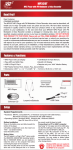
Virtual Reality Sound Labs
Automotive audio
installation technic
interior panels, ca
line (800)445-1797
TM
SERIOUS SOUND
Tools Needed Fo
Dear Customer,
CONGRATULATIONS. The VRA1.0 Mono Block Subwoofer Amplifier, when used as described, will give you years of
dependable service in your car, truck, RV or mini-van. We have taken numerous measures in quality control to
ensure that your product arrives in top condition, and will perform to your satisfaction. In the rare event that your
VRA1.0 Mono Block Subwoofer Amplifier contains a damaged or missing item, does not perform as specified,
requires warranty service or you have an installation problem. DO NOT RETURN THIS PRODUCT TO THE STORE.
Please call our TOLL-FREE number US (800-445-1797) and ask to speak with a member of our technical service
team, or submit your questions by E-Mail to [email protected] and a member of our technical
service team will respond by E-Mail to your questions. Our in-house technical service team will expedite delivery of
your part, advise you on installation, or help troubleshoot a problem with you. If your product needs warranty
service, our technical service team representative will help you obtain the fastest remedy possible under the
warranty.
• 300 Watts Total Peak Power
• 300 Watts Peak into 4 Ohm@ <1.0% THD +/- 5%
• 150 Watts RMS into 4 Ohm @ <1.0% THD +/- 5%
• Measured at 14.4 VDC Input Voltage
• Frequency Response: 20 Hz to 300 Hz +/- 3 db
• THD: Less than 1%
• Dimensions: 2” H X 10.25” W X 9.25” D
• Input Sensitivity: 250 mV to 6 Volts
• Signal to Noise Ratio: Greater than 95 db
• Bass Boost (Mega BassTM): 0 or +6 db
• Adjustable Crossover Freq.: 50 Hz to 250 Hz
• Output Impedance: 4 Ohm Recommended
• Fuse: 30 Amp Automotive Blade Type
• Dimensions: 5.08cm H x 26.04cm W x 23.5cm D
• Nail Set/Center P
• Phillips Screwdriv
We recommend
• Power Wire - 8 G
• Remote Wire - 20
Location
When choosing a lo
a location that allow
depending on phys
as is practically po
mount inverted or u
Before permanently
occupy in your car.
will allow you to est
Connect the fused 12
Turn on the amplifie
the Power Protectio
chassis ground, or
persists, call our-to
Allow f
carpet
• 1 Ground Wire
• 1 Self Tapping Screw
FRONT OF UNIT
• 4 Mounting Screws
• 12 Wire Nuts
• 4 Flat Washers
• 30 Amp Fuse
• Spade Terminal
• Crossover Frequency Adjustment (Freq.)
• Gain Adjustment (GAIN)
INPUT
GAIN
FREQ
Wat
Dus
Mod
mod
LINE OUT
LEFT
BASS BOOST
20Hz 300Hz
MIN MAX
RIGHT
OFF ON
• “RCA” Outputs To Be
Used With Multiple Amps
• “RCA” Inputs
• Bass Boost
REAR OF UNIT
Mark the holes
the 4 mounting
• 30 Amp Fuse
4 OHM SUB WOOFER
FUSE
MOSFET POWER SUPPLY
POWER REMOTE GROUND
3.
POWER
PROTECTION
• Terminals for
One 4 OHM Subwoofer
30 AMP
• Power,
Protection/Connection
Indicator Light
FOR USE WITH 4 to 8 OHM SUBWOOFERS ONLY!
• Terminals for
12 Volt DC Power,
Remote Switch,
And Chassis Ground
Drill 4 pilot hole
Make sure there
that can be dam
(Safety glasses sho
When moun
adjustments
Automotive audio equipment installations can be troublesome at times, even to the most experienced of
installation technicians. If you are not confident working with electrical wiring, removing and reinstalling
interior panels, carpeting, dashboards or other components of your vehicle, please call our toll-free help
line (800)445-1797 and our in-house technical service team will answer your installation questions.
Tools Needed For Installation:
• Nail Set/Center Punch
• Phillips Screwdriver
will give you years of
in quality control to
rare event that your
erform as specified,
CT TO THE STORE.
our technical service
mber of our technical
l expedite delivery of
duct needs warranty
possible under the
Volts
r than 95 db
or +6 db
50 Hz to 250 Hz
ecommended
ade Type
04cm W x 23.5cm D
Recommend
#1
• Hammer
• Wire Cutter
• Safety Glasses
• Marker/Pen
• Electrical Tape
• Electric Drill with 1/16" bit
Strip 1/2" of insulation
We recommend an Amplifier Installation Kit containing the following parts:
• Power Wire - 8 Gauge w/Terminal Lug
• Remote Wire - 20 Gauge OK
• Speaker Wire - 16 to 12 Gauge
• Input Wires - Shielded RCA cables
• RCA Cables & "Y" Adaptors
• After-Market Battery Terminal
Location
When choosing a location for the amplifier, keep in mind that the amplifier will generate heat. Place the amplifier in
a location that allows air to circulate around it. Amplifier location and installation will vary from vehicle to vehicle,
depending on physical layout of the vehicle. Carefully consider as many installation locations and configurations
as is practically possible DO NOT COVER the amp with carpet or enclose it behind interior panels. DO NOT
mount inverted or upside down. The amplifier may be mounted vertically.
Before permanently installing your VRA1.0 Amplifier, place the VRA1.0 Amplifier in the approximate place it will
occupy in your car. Run all power and speaker wires inside the vehicle toward the amplifier prior to mounting. This
will allow you to estimate how much wire you'll need and where to route the wires inside of your vehicle.
Connect the fused 12 Volt DC power wire, chassis ground cable, and remote wires. (SEE SECTION 3, ELECTRICAL CONNECTIONS)
Turn on the amplifier, if the Power Protection light is green, turn off the amplifier and proceed to the next section. If
the Power Protection light is red, review all of the connections and wires. You may have a loose connection, a bad
chassis ground, or an inadequate size power wire. If after reviewing all the connections and wires the problem
persists, call our-toll free help line for assistance.
Allow for air to circulate around the amplifier. Do not mount inverted or upside down. Do not cover with
carpeting or enclose it behind interior panels. Avoid mounting under a seat.
For Information and Technical Assistance,
Call Toll-Free in U.S.A. and Canada.
• 30 Amp Fuse
1-800-445-1797
Spade Terminal
PLEASE DO NOT RETURN PRODUCT TO STORE.
visit us on the WEB
WWW.VR-3.COM
Water Damage: Do not install this amplifier in a location that will expose it to water or moisture.
Dust or Dirt: Do not install this amplifier in a location that will expose it to dusty or dirty conditions.
Modifications: Do not open the amplifier for any reason or modify the amplifier in any way. If
modified in any way a fire hazard or malfunction may occur. Modification will void the warranty.
2.
With a hammer and nail set/center punch,
make dimple marks on the mounting
surface for each mounting screw.
Mark the holes for the 4 mounting screws in
the 4 mounting brackets with a marker/pen.
4.
3.
Drill 4 pilot holes with electric drill and 1/16" bit.
Make sure there is nothing behind mounting surface
that can be damaged when drilling the holes.
(Safety glasses should be worn at this time.)
1. Power Term
1. DISCONNEC
2. Strip ½" of in
after-market
To Amplifier Pow
3. Install a 35 a
4. Then route th
5. Strip 1/2" wid
6. Attach a spa
7. Loosen screw
8. Insert the spa
2. Remote Te
The REMOTE w
On most stereos,
1. Locate the
2. Splice REM
reach the
3. Loosen sc
4. Insert wire
5. Tighten sc
3. Ground Ter
1. The ground co
2. Find good, n
3. Drill a pilot ho
4. Use sandpap
5. Tightly fasten
A loose grou
You ma
This typ
o Be
e Amps
s for
ower,
itch,
Ground
Read the
any of t
technicia
amplifier
Recommende
1. POWER WIRE
When connectin
the spade termin
and the forks a
tighten the screw
2. REMOTE WIR
To connect the
twisted end und
tighten screw.
Secure amplifier with included screws and
washers using Phillips screwdriver.
When mounting the amplifier, make sure there is enough room for access to make
adjustments to the switches and adjustment screws.
3. GROUND WIR
To connect the
remove the scr
ground terminal
Put the screw t
then through th
tighten the screw
©2005 Virtual Re
t experienced of
g and reinstalling
our toll-free help
questions.
Read the following wiring instructions very carefully. If you have any trouble understanding
any of these instructions, have the amplifier professionally installed by an experienced
technician. Incorrect wiring will prevent the amplifier from operating, or will damage the
amplifier.
Recommended Method For Splicing Wires
#1
#2
#3
al Tape
Drill with 1/16" bit
es & "Y" Adaptors
ket Battery Terminal
ce the amplifier in
vehicle to vehicle,
nd configurations
panels. DO NOT
mate place it will
to mounting. This
vehicle.
AL CONNECTIONS)
he next section. If
connection, a bad
wires the problem
. Do not cover with
7
r moisture.
conditions.
any way. If
e warranty.
t/center punch,
the mounting
crew.
ed screws and
driver.
Strip 1/2" of insulation from the ends of the wires..
Twist together and bend as shown.
Wrap with electrical tape.
1. Power Terminal
1. DISCONNECT THE VEHICLE’S NEGATIVE (-) BATTERY TERMINAL FROM THE NEGATIVE BATTERY POST.
2. Strip ½" of insulation from the end of the 8 gauge power wire. Connect the 8 gauge power wire to the
after-market positive battery terminal according to the manufacturer's installation instructions.
After Market Positive Terminal (+)
To Amplifier Power Terminal
In-line 35 amp Fuse or Circuit Breaker
(not included)
Vehicle's Positive (+)
12 Volt power cable
3. Install a 35 amp fuse or 35 amp circuit breaker in the 8 gauge power wire as close to the battery as practical.
4. Then route the 8 gauge power wire from the 30 amp fuse or circuit breaker to the rear of the amplifier.
5. Strip 1/2" width of insulation from the end of the 8 gauge power wire.
6. Attach a spade lug on the end of 8 Gauge wire.
7. Loosen screw to open POWER connector plates on rear of amplifier.
8. Insert the spade lug between between the connector plates. Turn screw until power cable is tight.
2. Remote Terminal
The REMOTE wire connection automatically turns on your amplifier when your stereo is turned on.
On most stereos, this wire is marked as the REMOTE, ACCESSORY, or POWER ANTENNA.
1. Locate the REMOTE, ACCESSORY, or POWER ANTENNA on the stereo. (Refer to your stereo owner's manual.)
2. Splice REMOTE, ACCESSORY or POWER ANTENNA wire from rear of the stereo to a length of wire that will
reach the rear of the amplifier
3. Loosen screw and open REMOTE connector plates on rear of amplifier.
4. Insert wire end between the REMOTE connector plates.
5. Tighten screw closing REMOTE connector plates on wire.
3. Ground Terminal
1. The ground connection cable should be attached to clean, unpainted chassis metal for a good electrical connection.
2. Find good, non-rusted chassis metal, as close to the amplifier as possible.
3. Drill a pilot hole with a 1/16" drill bit.
4. Use sandpaper to expose an area of bare metal around the pilot hole about the size of a dime.
5. Tightly fasten the provided ground cable with the self tapping sheet metal screw to the chassis metal.
A loose ground will cause distortion and popping noises in the speakers.
You may purchase shielded RCA cables that have a remote wire that is built right into the cable.
This type of cable makes it possible to route both RCA cable and remote wire at the same time.
Recommended Method For Attaching Wires to Terminals
1. POWER WIRE
When connecting the power wire, place
the spade terminal under the contact plate
and the forks around the screw. Then
tighten the screw.
2. REMOTE WIRE
To connect the remote wire, place the
twisted end under the contact plate and
tighten screw.
3. GROUND WIRE
To connect the supplied ground wire,
remove the screw and contact from the
ground terminal on the rear of the amplifier.
Put the screw through the contact plate,
then through the ground wire, and finally
tighten the screw.
3. GROUND WIRE
1. POWER WIRE
2. REMOTE WIRE
©2005 Virtual Reality Sound LabsTM. All designs, logos and images are the exclusive property of Virtual Reality Sound LabsTM and/or its affiliates. Design Patent Pending. All rights reserved. 050505
The line inputs on the front of the amplifier receive low level, high impedance signals from the low level RCA
outputs of the car stereo. The amplifier receives the signals and converts them to high level, low impedance
signals to be used to drive the speakers. All of the amplifiers line inputs need to be connected to the car stereo,
in order to use all of the speaker outputs.
GAIN Contr
GAIN
MIN
FIGURE 1.
MAX
Speaker
&
Antenna wires
Generic Car Stereo
Frequency
Left Channel
Right Channel
FREQ
50Hz 250Hz
Shielded RCA Cable
The pre-amp line outputs allow
unamplified signals to pass
through the amplifier to be used
in a multiple amplifier stereo
system.
LEFT CHANNEL
BASS BOOST
OFF ON
BASS BOOST
(optional)
RIGHT CHANNEL
One Single
To wire a 4 ohm si
the amplifier, conne
terminal to the subw
Then connect th
terminal to the subw
FRONT OF AMPLIFIER
RCA "Y" Adaptors Not Included
DO NOT
Your car stereo may only has 2 line outputs (left & right),
RCA "Y" Adaptors will be needed to split the left and
right signals into 2 right channels and 2 left channels,
one of each channel for both the front and rear
inputs.(See Fig.1)
Two Single
To wire two single v
connect the ampl
positive (+) termina
Next connect the n
to the positive (+) te
Then connect the n
to the negative term
Shielded RCA Cable Not Included
For best sound performance use Shielded RCA Cables
to connect the Line Outputs from your stereo to the
Amplifier Line Inputs. Shielded RCA Cables prevent
electrical interference from the vehicles electrical
system, and also radio frequency interference.
This Is T
Two 4 O
High Level to Low Level Input Adaptor Not Included
If your stereo does not have RCA type output jacks, a
high level to low level adaptor will need to be
purchased. The high level to low level adaptor takes the
signals from the car stereo's speaker wires and
converts them to low level, high impedance signals to
be used by the amplifier. Install the converter according
to the manufacturers' instructions.
One Dual Vo
Do not splice RCA jacks directly to
the car stereo's speaker wires.
Unused Speaker Wires from Head Unit
You must trim the unused speaker wires on the stereo and
wrap with electrical tape as shown to prevent a short circuit.
The colors of the jacks on the RCA
cables and adaptors shown here
are for illustration purposes.
The color of the cables and adaptors
that you purchase for installation will
vary by manufacturer.
To wire a dual voic
amplifier’s positive
terminal of voice co
Next connect the n
“A” to the postive (
Then connect the
amplifier to the ne
“B”.
the low level RCA
el, low impedance
d to the car stereo,
p line outputs allow
signals to pass
amplifier to be used
le amplifier stereo
RCA jacks directly to
s speaker wires.
e jacks on the RCA
ptors shown here
n purposes.
ables and adaptors
e for installation will
urer.
GAIN Control
The GAIN control matches the line output of your car stereo's RCA jacks, to the line inputs of
the amplifier. When you have completed installing the amplifier, the gain control must be set at
no more than half way to prevent damage to the amplifier. Play a CD or cassette on the car
stereo, set the BASS and TREBLE at 50%, and set the equalizer, if you have one, to flat across
all frequencies, also set the left & right balance and front & rear fader settings are set in the
middle. If you have any distortion at these setting, then turn the gain down until the distortion
disappears.
GAIN
MIN
What is the per c
150 Watts RMS in
MAX
The frequency adjustment screw (FREQ.) only has an effect if the crossover switch is set to
"BASS" or "TREBLE", when the crossover is set to FLAT it has no effect.
To set the FREQ. turn FREQ. all the way to the right, this allows a range of sound from 50 Hz 250 Hz to the subwoofer. As you turn the FREQ. to the left (counterclockwise), you will be
cutting off the high frequencies coming from the subwoofer.
50Hz 250Hz
BASS BOOST
(optional)
Do I need a stiffe
It never hurts to ha
The VRPC1000 Po
Why does the Po
Check your POWE
carry the current d
Why does the Po
This typically indic
This condition will
BASS BOOST
OFF ON
What if my car ra
You will need a co
the converter man
What should I do
Connect the ampl
turn the amplifier o
Frequency Adjustment Screw
FREQ
Can I hook up tw
Only if both subwo
The BASS BOOST switch adds an additional 6dB at 50Hz. It normally is set to OFF. Turning
ON BASS BOOST, will not make the bass sound better, it only adds volume to the lowest
frequency. Bass Boost should not be turned on if you have Bass Control or Loudness on your
stereo head unit.
Why don’t I have
Check the control
Also check or repl
One Single Voice Coil Subwoofer
4 OHM SUBWOOFER
To wire a 4 ohm single voice coil subwoofer to
the amplifier, connect the amplifier’s positive (+)
terminal to the subwoofer’s positive (+) terminal.
Then connect the amplifier’s negative (-)
terminal to the subwoofer’s negative (-) terminal.
DO NOT WIRE 2 SUBWOOFERS IN PARALELL!
Limited
Two Single Voice Coil Subwoofers
4 OHM SUBWOOFER
To wire two single voice coil 4 ohm subwoofers in series
connect the amplifier’s positive (+) terminal to the
positive (+) terminal of subwoofer “A”.
Next connect the negative (-) terminal of subwoofer “A”
to the positive (+) terminal of subwoofer “B”.
Then connect the negative (-) terminal of the amplifier
to the negative terminal of subwoofer “B”.
Subwoofer "A"
Subwoofer "B"
This Is The Only Safe Way To Connect
Two 4 Ohm Subwoofers To The VRA1.0 Amplifier
One Dual Voice Coil Subwoofer
To wire a dual voice coil subwoofer connect the
amplifier’s positive (+) terminal to the positive (+)
terminal of voice coil “A”.
Next connect the negative terminal of voice coil
“A” to the postive (+) terminal of voice coil “B”.
Then connect the negative (-) terminal of the
amplifier to the negative (-) terminal voice coil
“B”.
VIRTUAL REALITY S
LABSTM warrants, to
as part of our comm
production methods
without notice.
CONDITIONS OF W
If during the 30 day
product, without cha
1. All repairs must be
2. The equipment mu
3. The replacement o
4. All warranty claims
5. Repair or replacem
warranty.
6. In the case of car s
incurred for the remo
7. VIRTUAL REALITY
OWNER'S RESPON
VIRTUAL REALITY S
SHOULD YOU HAVE
PLEASE CALL TOLL
4 Ohms + 4 Ohms = 8 Ohms
Voice Coil "A"
In order to provide y
1. Include a copy of y
2. If it is necessary t
prepaid to the follow
3. Please include a d
4. If your product is
replaced at no charg
warranty. This warran
VIRTUAL REALITY S
VIRTUAL REALITY S
and seller shall not b
Voice Coil "B"
©2005 Virtual Reality Sound LabsTM. A
to the line inputs of
ntrol must be set at
cassette on the car
e one, to flat across
ttings are set in the
n until the distortion
ver switch is set to
sound from 50 Hz ckwise), you will be
set to OFF. Turning
olume to the lowest
or Loudness on your
ubwoofer "B"
8 Ohms
ce Coil "A"
ce Coil "B"
What is the per channel RMS power of this amplifier?
150 Watts RMS into 4 Ohm @ <1.0% THD +/- 5%
Can I hook up two subwoofers to this amplifier?
Only if both subwoofers are wired in series.
What if my car radio doesn't have RCA line outputs?
You will need a converter used to change the signals from the speaker wires to RCA line level inputs. Follow
the converter manufacturer's installation instructions.
What should I do if my car radio doesn't have a remote wire?
Connect the amplifier remote terminal to a switched 12 Volt circuit controlled by the ignition switch. This will
turn the amplifier off when the ignition switch is turned off.
Do I need a stiffening capacitor with this amplifier?
It never hurts to have extra reserve power when operating an amplifier of this caliber.
The VRPC1000 Power Capacitor is the perfect companion to the VRA2.0 Amplifier.
Why does the Power / Protect LED switch between green & red?
Check your POWER and GROUND connections. Also check to see that your wire size is sufficient to
carry the current demand. Check for improper impedance loads
Why does the Power / Protect LED stay red?
This typically indicates that one or more of the MOSFET output transistors has shorted.
This condition will not fix itself. The amplifier must be returned to Virtual Reality Sound Labs for repair.
Why don’t I have any sound when the protection light is green?
Check the controls on the stereo, make sure that the volume, balance, and fader controls are set properly.
Also check or replace the RCA cables. They may be defective.
For Information and Technical Assistance,
Call Toll-Free in U.S.A. and Canada.
1-800-445-1797
PLEASE DO NOT RETURN PRODUCT TO STORE.
visit us on the WEB
WWW.VR-3.COM
Limited Warranty
VIRTUAL REALITY SOUND LABSTM products are designed and manufactured to provide a high level of trouble-free performance. VIRTUAL REALITY SOUND
LABSTM warrants, to the original purchaser, that its products are free from defects in material and workmanship for 30 days from the date of original purchase,
as part of our commitment to product excellence. VIRTUAL REALITY SOUND LABSTM and/or it’s affiliates routinely improves the designs, materials or
production methods of its existing products. Because it is impractical to publicize all changes in every product, we reserve the right to make such changes
without notice.
CONDITIONS OF WARRANTY:
If during the 30 day warranty period your new product is found to be defective, VIRTUAL REALITY SOUND LABSTM will repair such defect, or replace the
product, without charge for parts or labor subject to the following conditions:
1. All repairs must be performed by VIRTUAL REALITY SOUND LABSTM and/or it’s affiliates in Eatontown, New Jersey.
2. The equipment must not have been altered or been damaged through negligence, accident, or improper operation.
3. The replacement of parts are exempted from this warranty when replacement is necessary due to normal wear and tear.
4. All warranty claims must be accompanied by a copy of the sales receipt or bill of sale.
5. Repair or replacement parts supplied by VIRTUAL REALITY SOUND LABSTM under this warranty are protected only for the unexpired portion of the original
warranty.
6. In the case of car stereos, this warranty does not extend to the elimination of car static or motor noise; correction of antenna problems; costs
incurred for the removal or reinstallation of the product; damage to tapes, speakers, accessories or car electrical systems.
7. VIRTUAL REALITY SOUND LABSTM will not be responsible for any charge incurred for installation.
OWNER'S RESPONSIBILITIES:
VIRTUAL REALITY SOUND LABSTM will make every effort to provide warranty service within a reasonable period of time.
SHOULD YOU HAVE ANY QUESTIONS ABOUT SERVICE RECEIVED, OR IF YOU WOULD LIKE ASSISTANCE IN OBTAINING SERVICE,
PLEASE CALL TOLL FREE 1-800-445-1797, 8:30am - 4:30pm EST.
In order to provide you with the proper warranty service, we request that you adhere to the following procedure:
1. Include a copy of your sales receipt or bill of sale with your unit when it is returned for warranty service.
2. If it is necessary to return your product for service, please return it securely packed, preferably in the original shipping carton, and freight and insurance
prepaid to the following address: VIRTUAL REALITY SOUND LABSTM, Service Department, 6 G Industrial Way West, Eatontown, New Jersey 07724.
3. Please include a detailed explanation of the problem you are having.
4. If your product is found by VIRTUAL REALITY SOUND LABS to have a defect in material or workmanship, within the warranty period, it will be repaired or
replaced at no charge and returned to you prepaid. Where permitted by Iaw VIRTUAL REALITY SOUND LABSTM liability shall be limited to that set forth in this
warranty. This warranty shall be the exclusive remedy of the purchaser.
VIRTUAL REALITY SOUND LABSTM makes no other warranty of any kind, expressed or implied; and all implied warranties, are hereby disclaimed by
VIRTUAL REALITY SOUND LABSTM and excluded from this warranty, VIRTUAL REALITY SOUND LABSTM and/or it’s affiliates, the manufacturer, distributor
and seller shall not be liable for any injury, loss or damage, incidental or consequential, arising out of the use or intended use of the product.
©2005 Virtual Reality Sound LabsTM. All designs, logos and images are the exclusive property of Virtual Reality Sound LabsTM and/or its affiliates. Design Patent Pending. All rights reserved. 050505 Printed in China 00000