1
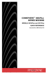
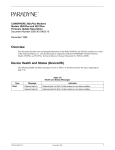
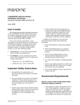
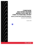
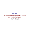
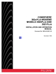
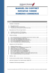
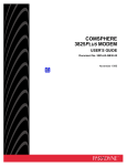
TM
COMSPHERE 3800Plus Modems
Synchronous Data Compression Feature
Document Number 3980-A2-GZ40-20
November 1996
Overview
The Paradyne proprietary Synchronous Data Compression (SDC) feature allows an increase of throughput in data
transmission, and has an error correcting procedure so that transmitted data is less sensitive to channel
disturbances.
The ITU-T recommendations V.42bis and V.42 have data compression and error correcting (EC) procedures for
DCEs connected to asynchronous DTEs. These procedures form the basis of Paradyne’s SDC feature.
With the SDC feature, two DTEs can exchange data via a synchronous protocol (Figure 1) while the DCE
provides the new synchronous data compression and error correction functions (Figure 2). The synchronous data
from the local DTE, after compression, is inserted into DCE frames which are sent to the remote DCE. Inverse
operations then occur at the remote DCE.
SDC can be used with V.34 and V.32 family modulations on dial or leased lines, and in a dial backup or standby
mode.
SDC is available as an installable option beginning with firmware Release 3.0.
SYNCHRONOUS PROTOCOL
SYNCHRONOUS
DTE
19.2 Kb/s
9.6 Kb/s
DCE
19.2 Kb/s
DCE
SYNCHRONOUS
DTE
495-14784
Figure 1. Sample DTE Exchange of Data via Synchronous Protocol and SDC
3980-A2-GZ40-20
November 1996
1
DCE
SYNCHRONOUS
DTE
INTERCHANGE
CIRCUITS
FUNCTION
DATA
COMPRESSION
FUNCTION
ERROR
CORRECTION
FUNCTION
SIGNAL
CONVERTER
LINE
CONTROL
FUNCTION
495-14785
Figure 2. Synchronous Data Compression
Installing the SDC Feature
The SDC feature can be installed using AT commands or the DCP.
Installing the SDC Feature Using the DCP
To install SDC using the DCP, use this procedure.
1. Press the
key until Control appears. Press F1.
2. Press the
key until Install appears. Press F1.
3. If the SDC option is not visible, press the
key until SDC appears.
NOTE: If SDC has been installed on this modem, SDC will not appear.
4. Press the function key (F1, F2, or F3) directly beneath SDC.
5. Enter the Product Authorization Code for SDC:
• Use the
and
keys to move the cursor to each digit position.
• Press F2 to increment each digit to the required value. The Product Authorization Code for SDC is:
011993
6. Once the digits are set to the required values, press F1 (to select Ent).
7. Press the
key to go to the top of the menu tree, then press the
8. Press the
key until Options appears. Press F2 or F3.
key until Status appears. Press F1.
9. Scroll through the installed options. SDC is listed among them.
2
November 1996
3980-A2-GZ40-20
10. Perform a power reset:
• For a standalone modem, turn the Power switch to the Off position, then to the ON position, or
• For a carrier-mounted modem, release the lock, slide the modem part of the way out of the carrier, then
replace it and lock it in place.
11. Set the SDC configuration options suitable for your environment. See Tables 1 and 2.
Installing the SDC Feature Using AT Commands
To install SDC using AT commands, use this procedure.
1. Attach a DTE to the modem.
2. Load the Async Dial factory template:
• From the DCP, select Async Dial from the Factory group of the Configure branch, or
• If AT commands are enabled, enter the AT&F0 command.
3. Install the SDC feature. Enter the command: AT&&I12=011993
The modem responds OK.
4. Perform a power reset. Enter the command: ATZ9
5. Check the installed features. Enter the command: AT&&I0
The modem responds with a list of features installed in your modem, including SDC.
6. Set the SDC configuration options suitable for your environment. See Tables 3 and 4.
Menu Status and Result Codes
When SDC is active and the modem is online, the top line of the DCP display shows Online:mrV42t,
Leased:mrV42t, Backup:mrV42t, or Stndby:mrV42t, where mr is the modem rate. For example,
Online:33.6V42t is displayed on the DCP of a modem using SDC and connected to a dial line at 33,600 bits per
second (bps).
When extended result codes are set to contain the data compression protocol, and SDC is active, connect
messages include the characters V42t. For example, when a modem with SDC active connects to a dial line at
33,600 bps, the result code CONNECT 33600/V42t/RX=33600/TX=33600 is sent to the DTE.
3980-A2-GZ40-20
November 1996
3
SDC User Interface
When SDC is enabled, the following configuration options are available to set up the SDC feature. Some of the
configuration options are not displayed unless SDC is enabled.
V.42/MNP/Buffer (see Table 1)
• Sync Comp Mode
• SDC Negotiation
• SDC Idle Fill
• SDC Bit Encoding
• Sync DTE CRC
• SDC Delay Min
• Sync Flow Control
• TX Buff Disc Delay
• RX Buff Disc Delay
• Max Frame Size
• Cellular Enhance
DTE Interface (see Table 2)
• Sync DTE Rate
• Tx Clock Source
4
November 1996
3980-A2-GZ40-20
Table 1
(1 of 3)
V.42/MNP/Buffer Configuration Options for SDC
Sync Comp Mode: DirectMode
Nxt DirectMode HDLC/SDLC
This configuration option only appears if Async/Sync Mode is configured for Sync.
Synchronous Compression Mode. Enables and disables synchronous data compression.
DirectMode – Disables the Synchronous Data Compression mode.
HDLC/SDLC – Enables the Synchronous Data Compression mode
The AT command for Sync Comp Mode is #SCn. See Table 3, page 9.
SDC Negotiation: LAPM_Buffer
Nxt LAPM_Buffer LAPM_Discon
This configuration option only appears when the Async/Sync Mode configuration option is set to Sync and Sync
Comp Mode configuration option is not set to DirectMode.
Synchronous Data Compression Negotiation. Determines the type of negotiation used when the modem attempts to
connect using SDC. See Table 5, page 15.
Link Access Procedure for Modems or Buffer – The modem attempts to establish an SDC connection. If the remote
modem has SDC capability, then the connection is established with SDC active. If the remote synchronous modem does
not have SDC capability, then the local connection is made in Buffer mode.
Link Access Procedure for Modems or Disconnect – The modem attempts to establish an SDC connection. If the
remote modem has SDC capability, then the connection is established with SDC active. If the remote modem does not
have SDC capability, then no connection occurs and the modem generates a disconnect.
The AT command for SDC Negotiation is S28=n. See Table 4, page 10.
SDC Idle Fill: Flag_Fill
Nxt Flag_Fill Mark_Fill
This configuration option only appears when the Async/Sync Mode configuration option is set to Sync and Sync
Comp Mode configuration option is not set to DirectMode.
Synchronous Data Compression Idle Fill. Determines whether the modem uses an HDLC flag or mark to fill the time
between DTE frame transfers.
Flag_Fill – Causes the modem to fill the time between DTE frame transfers with HDLC flags.
Mark_Fill – Causes the modem to fill the time between DTE frame transfers with marks.
The AT command for SDC Idle Fill is S29=n. See Table 4, page 10.
SDC BitEncoding: NRZ
Nxt NRZ NRZI
This configuration option only appears when the Async/Sync Mode configuration option is set to Sync and Sync
Comp Mode configuration option is not set to DirectMode.
Synchronous Data Compression Bit Encoding. Determines the type of bit encoding scheme (NRZ or NRZI) the modem
uses when transmitting synchronous DTE data.
NRZ – Causes the modem to use the standard Non Return to Zero bit encoding scheme.
NRZI – Causes the modem to use the Non Return to Zero Inverted bit encoding scheme.
The AT command for SDC Bit Encoding is S31=n. See Table 4, page 11.
3980-A2-GZ40-20
November 1996
5
Table 1
(2 of 3)
V.42/MNP/Buffer Configuration Options for SDC
SyncDTE CRC: Ignore
Nxt Ignore CRC16
This configuration option only appears when the Async/Sync Mode configuration option is set to Sync and Sync
Comp Mode configuration option is not set to DirectMode.
Synchronous DTE CRC. Determines whether the CRC of the DTE frame is transmitted from modem to modem.
Ignore – No assumption is made about the CRC type. The CRC is transmitted along with the other data in the frame.
CRC16 – The CRC is known to be the 16-bit CRC for HDLC frames defined by ITU-T (generator polynomial x16 +
x12 + x5 + 1). It is removed from the DTE frame by the sending modem and added to the DTE frame by the receiving
modem.
The AT command for SyncDTE CRC is S32=n. See Table 4, page 11.
SDC Delay Min: Off
Nxt Off Rx_Clock
This configuration option only appears when the Async/Sync Mode configuration option is set to Sync and Sync
Comp Mode configuration option is not set to DirectMode.
Synchronous Data Compression Delay Minimization. Allows the modem to transmit a DTE frame to its DTE in a
discontinuous way to minimize the delay introduced by SDC processing.
Off – The modem does not begin transmitting a frame to its DTE until the entire frame has been received.
Rx_Clock – The modem begins to transmit data from a DTE frame to its DTE even if the end of the DTE frame has not
yet been received by the modem. The receive clock (circuit 115) is clamped when the beginning of a DTE frame has been
transmitted to the DTE and no other data from this DTE frame has been received by the modem. As soon as data from
the current DTE frame can be transmitted to the DTE, the receive clock is released. The Rx_Clock option appears only if
the Tx Clock Source configuration option is set to Internal.
The AT command for SDC Delay Min is #DMn. See Table 3, page 9.
Sync Flow Cntrl: None
Nxt None Tx_Clock CTS_SyncDTE
This configuration option only appears when the Async/Sync Mode configuration option is set to Sync and Sync
Comp Mode configuration option is not set to DirectMode.
Synchronous Flow Control. Controls the type of synchronous data flow control while using data compression.
None – Modem does not control the flow from the synchronous DTE.
Tx_Clock – The transmit clock (circuit 114) clamps when the modem is unable to accept supplementary data from the
DTE. Tx_Clock appears only if the Tx Clock Source configuration option is set to Internal.
CTS_SyncDTE – CTS signal circuit (106) is set to OFF when the modem is unable to accept supplementary data from
the DTE.
The AT command for Sync Flow Cntrl is #Qn. See Table 3, page 9.
6
November 1996
3980-A2-GZ40-20
Table 1
(3 of 3)
V.42/MNP/Buffer Configuration Options for SDC
TXBuffDiscDelay: 10sec
Nxt 10sec Disable 60sec
This configuration option only appears when Async/Sync Mode is configured for Async, and Error Control Mode
is not configured for DirectMode, or when Async/Sync Mode is configured for Sync and Sync Comp Mode is not
configured for DirectMode.
Transmit Buffer Disconnect Delay. Determines how long the modem continues to transmit data stored in its Transmit
buffer when the modem is commanded to disconnect by a locally attached DTE.
Disable – Modem disconnects immediately without attempting to send data stored in its buffer.
10, 60 sec – Maximum amount of time the modem tries to empty its buffer before disconnecting. In both cases (10 sec
and 60 sec), the modem disconnects much sooner if it can empty its buffer.
The AT command for TXBuffDiscDelay is S49=n.
RXBuffDiscDelay: 10sec
Nxt 10sec Disable 60sec
This configuration option only appears when Async/Sync Mode is configured for Async, and Error Control Mode
is not configured for DirectMode, or when Async/Sync Mode is configured for Sync and Sync Comp Mode is not
configured for DirectMode.
Receive Buffer Disconnect Delay. Determines how long the modem continues to send to the DTE data stored in its
Receive buffer when the modem is commanded to disconnect by a locally attached DTE, or detects a line disconnect.
Disable – Modem disconnects immediately without attempting to send data stored in its buffer.
10, 60 sec – Maximum amount of time the modem tries to empty its buffer before disconnecting. In both cases (10 sec
and 60 sec), the modem disconnects much sooner if it can empty its buffer.
The AT command for RXBuffDiscDelay is S39=n.
Max Frame Size: 256
Nxt 256 192 128 64 32 16
This configuration option only appears when Async/Sync Mode is configured for Async, and Error Control Mode
is not configured for BufferMode or DirectMode, or when Async/Sync Mode is configured for Sync and Sync
Comp Mode is not configured for DirectMode.
Maximum Frame Size. Sets the maximum frame size for V.42 and MNP. For MNP operation, 64 is the minimum value.
Any value less than that will automatically default to 64. For cellular applications, at least one of the sides should be set to
a low value. A setting of 32 is recommended. Only one modem needs this setting; both modems will automatically default
to the greatest common value.
The AT Command for Max Frame Size is \ An.
CellularEnhance: Disable
Nxt Disable Enable
This configuration option only appears when Async/Sync Mode is configured for Async, and Error Control Mode
is configured for V42/MNPorBfr, V42MNPorDsc, LAPM_or_Disc, or LAPM_or Bfr, or when Async/Sync Mode is
configured for Sync and Sync Comp Mode is not configured for DirectMode.
Cellular Enhancement. When enabled, the modem uses non-standard techniques to enhance V.42 operation for cellular
applications. It is still compatible, however, with modems which do not have the cellular enhancement implemented or
enabled.
The AT command for CellularEnhance is S91=n.
3980-A2-GZ40-20
November 1996
7
Table 2
DTE Interface Configuration Options for SDC
Sync DTE Rate: 128000
Nxt 128000 115200 112000 96000 76800 72000 64000 57600 56000 48000 38400 28800 19200 14400
9600 4800 2400 1200
This configuration option does not appear when:
• Async/Sync Mode configuration option is set to Async.
• Sync Comp Mode configuration option is set to DirectMode.
• Tx Clock Source configuration option is set to External.
• The SDC feature is disabled.
Synchronous DTE Data Rate. Identifies the synchronous DTE’s operating rate to the modem. Data rates from
128,000 bps to 1200 bps are supported.
NOTE: A cable less than fifty feet in length is required for rates over 19,200 bps. Data synchronization at rates over
57,600 bps is sensitive to cable length and capacitance, and the DTE’s drivers and receivers. External transmit
clocking may be required.
The AT command for Sync DTE Rate is S30=n. See Table 4, page 10.
Tx Clock Source: Internal
Nxt Internal External RXC_Loop
This configuration option only appears when Async/Sync Mode is configured for Sync.
Transmit Clock Source. Determines the source of timing for synchronous data transmitted from the DTE.
Internal – The transmit data’s clock source is derived from the modem’s internal clock. This clock is available as an
output on Pin 15 (TXC) of the EIA-232-D interface.
External – The transmit data’s clock source is provided by the DTE on Pin 24 (XTXC) on the EIA-232-D interface.
Receive Clock Loop – The modem’s transmit clock is derived from its received analog signal. The derived clock is
available as an output on Pin 15 (TXC) of the EIA-232-D interface.
NOTE: RXC_Loop does not appear if SDC is enabled.
NOTE: TMp tributaries are forced to RXC_Loop.
The AT command for Tx Clock Source is &Xn.
8
November 1996
3980-A2-GZ40-20
Table 3
AT Commands for SDC
AT
Command
#DMn
Description
SDC Delay Minimization.
Minimizes the delay introduced by SDC by allowing the modem to transmit a
DTE frame to its DTE in a discontinuous way.
#DM0
#DM1
DCP LCD
Command
Sequence
Configure\Edit\
V42/MNP/Buffer
No delay minimization. The modem does not begin transmitting a
frame to its DTE until the entire frame has been received.
Delay minimization. The modem begins to transmit data from a
DTE frame to its DTE even if the end of the DTE frame has not yet
been received by the modem.
The factory setting is No Delay Minimization.
#Qn
Sync Flow Ctrl. Synchronous Flow Control of DTE.
Controls the type of synchronous data flow control while using data
compression.
#Q0
#Q1
#Q2
Configure\Edit\
V42/MNP/Buffer
No flow control.
Flow control using transmit clock (circuit 114).
Flow control using CTS (circuit 106).
The factory setting is No Flow Control.
#SCn
Sync Comp Mode. Synchronous Compression Mode.
Enables and disables synchronous data compression.
#SC0
#SC1
Configure\Edit\
V42/MNP/Buffer
Disable Synchronous Data Compression mode.
Enable Synchronous Data Compression mode.
The factory setting is Disable.
3980-A2-GZ40-20
November 1996
9
Table 4
(1 of 2)
S-Registers for SDC
S-Register
S28
Description
SDC Negotiation.
Controls negotiation between two modems attempting to connect using SDC.
DCP LCD
Command
Sequence
Configure\Edit\
V42/MNP/Buffer
Register has the following values:
0 = LAPM_Buffer
1 = LAPM_Discon
The factory setting is LAPM_Buffer.
S29
SDC Idle Fill.
Determines whether the modem uses an HDLC flag or mark to fill the time
between DTE frame transfers.
Configure\Edit\
V42/MNP/Buffer
Register has the following values:
0 = Flag_Fill
1 = Mark_Fill
The factory setting is Flag_Fill.
S30
Sync DTE Rate. Synchronous DTE Rate.
Identifies the synchronous DTE’s operating rate to the modem.
Configure\Edit\
DTE Interface
Register has the following values:
0 = 128,000 bps
1 = 115,200 bps
2 = 112,000 bps
3 = 96,000 bps
4 = 76,800 bps
5 = 72,000 bps
6 = 64,000 bps
7 = 57,600 bps
8 = 56,000 bps
9 = 48,000 bps
10 = 38,400 bps
11 = 28,800 bps
12 = 19,200 bps
13 = 14,400 bps
14 = 9600 bps
15 = 4800 bps
16 = 2400 bps
17 = 1200 bps
The factory setting is 128,000 bps.
10
November 1996
3980-A2-GZ40-20
Table 4
(2 of 2)
S-Registers for SDC
S-Register
S31
Description
SDC Bit Encoding.
Determines the type of bit encoding used when transmitting synchronous DTE
data.
DCP LCD
Command
Sequence
Configure\Edit\
V42/MNP/Buffer
Register has the following values:
0 = NRZ
1 = NRZI
The factory setting is NRZ.
S32
SyncDTE CRC.
Determines whether the CRC of the DTE frame is transmitted from modem to
modem.
Configure\Edit\
V42/MNP/Buffer
Register has the following values:
0 = Ignore
1 = CRC16
The factory setting is Ignore.
3980-A2-GZ40-20
November 1996
11
Synchronous Data Format
The SDC feature supports the High-level Data Link Control (HDLC) and Synchronous Data Link Control
(SDLC) type protocols for synchronous DTE data. An HDLC frame is composed of an information field
containing the data to transmit, plus an overhead (address, control, and FCS fields) used by the DTE protocol.
Flags opening and closing the HDLC frame serve as frame delimiters (Figure 3).
FLAG
ADDRESS
CONTROL
INFORMATION
FCS
FLAG
495-14783
Figure 3. Synchronous Data Format
A 3800Plus modem with the SDC feature supports DTE frame sizes up to 4300 bytes. This conforms to the X.25
recommendation which defines a maximum size of data packets as equal to 4096 bytes.
If the modem has the SDC Delay Min configuration option set to Rx_Clock, there is no limitation on the DTE
frame size for the DTE frames transmitted from the remote modem to this local modem, since the whole frame
need not be buffered.
The SyncDTE CRC configuration option determines whether the CRC of the DTE frame (the FCS field) is
transmitted. If the CRC type is known to be the 16-bit CRC for HDLC frames as defined by ITU-T (generator
polynomial x16 + x12 + x5 + 1), the CRC can be removed by the local modem and added to the DTE frame by the
remote modem.
SDC Algorithm
The compression algorithm is based on V.42bis British Telecom Lempel ZIV (BLTZ).
DTE and DCE Frames
Data exchanged between the local and remote DCEs is according to the LAPM protocol. The structure of a
LAPM frame (DCE frame) is identical to the HDLC frame. The data from the DTE is compressed into the
information field of the DCE frame. After compression, one DTE frame is segmented into one or several DCE
frames.
12
November 1996
3980-A2-GZ40-20
Data Synchronization
Data exchanged between the synchronous DTE and the modem is synchronized by two clock signals. Data
coming from the DTE is synchronized by the transmit clock and data received by the DTE is synchronized by the
receive clock. The transmit clock is provided by the modem on circuit 114 or by the synchronous DTE on
circuit 113. The receive clock is provided by the modem on circuit 115.
When the transmit clock is provided by the modem, the transmit and receive clocks are locked on the same clock
source internal to the modem. In this configuration, the user can select rates on the DTE-DCE line (or clock
frequencies) in the range from 1.2 kHz to 128 kHz.
When the transmit clock is provided by the DTE, the receive clock is set by the modem equal to the DTE clock
(Figure 4). When SDC is in use, the Tx Clock Source configuration option cannot be set to Receiver Clock Loop.
NOTE
When faster speeds are used (above 57.6 kHz), and the transmit clock is
provided by the modem, data transmission can be sensitive to DTE cable
length and capacitance, as well as the DTE’s drivers and receivers. Should
you encounter bit errors related to the above conditions, you may want to
change the Tx Clock Source configuration option setting to External
(provided the DTE can support the required transmit clock signal) or
change the length of the DTE cable.
DCE
XTCLK (113)
TXC (114)
DTE
RXC (115)
CLOCK
SOURCE
495-14782
Figure 4. Clocks at the DTE–DCE Interface
3980-A2-GZ40-20
November 1996
13
Flow Control Method
The data transmitted from the DTE is sent to the DCE at a rate determined by the transmit clock frequency. When
SDC is active, this data is then compressed in the DCE and sent to the remote DCE at the line rate less than the
rate between the DTE and DCE (usually twice, three, or four times less). If the data sent by the DTE is not
compressible, or bad line conditions cause retransmissions between the two DCEs, then the transmitting DCE
must indicate to the transmitting DTE its temporary inability to accept more data; this is flow control. Flow
control is also required in Buffer mode since the DTE rate and line rate can be different. Three methods are used
to control the DTE flow:
• Hardware signal CTS (circuit 106).
• Transmit clock (circuit 114). If the transmit clock is clamped, then the DTE stops sending data. This
method only works when the transmit clock is provided by the modem.
• Natural flow control. Some DTEs can only send a limited number of information frames without any
acknowledgment from the remote DTE. This number is the acknowledgment window size. If the DCE
buffers this number of DTE frames, it will not receive another DTE frame. This is equivalent to the
SyncFlowControl configuration option being set to None.
SDC Negotiation
The use of SDC and the values of the associated parameters are negotiated at link establishment via a protocol.
The three associated parameters have the same meaning as those used for asynchronous data compression:
• Dictionary size parameter
• Maximum string length parameter
• Data compression request parameter
The SDC Negotiation configuration option determines how two modems connect when one or both modems have
SDC enabled. Two settings are available in the SDC Negotiation configuration option: LAPM_Buffer and
LAPM_Discon.
Table 5 shows the six possible SDC Negotiation configuration scenarios.
14
November 1996
3980-A2-GZ40-20
Table 5
SDC Negotiation Configuration Scenarios
Answering Modem
Originating Modem
Negotiation Results
SDC enabled with LAPM_Buffer
negotiation.
SDC enabled.
SDC connection.
SDC enabled with LAPM_Discon
negotiation.
SDC enabled.
SDC connection.
SDC enabled with LAPM_Buffer
negotiation.
SDC disabled.
Buffer mode connection.*
SDC enabled with LAPM_Discon
negotiation.
SDC disabled.
Disconnect.**
SDC disabled.
SDC enabled with LAPM_Buffer negotiation.
Buffer mode connection.*
SDC disabled.
SDC enabled with LAPM_Discon negotiation.
Disconnect.***
* If during the negotiation phase, the modem with SDC enabled receives data from the remote modem indicating that it
has SDC disabled, the link will not be established between the two modems. For example, the link will not be
established if the remote modem is configured for Async mode with an EC mode of V42/MNPorBfr, V42/MNPorDsc,
LAPM_Buffer, or LAPM_Discon.
** On a leased line, the originating modem sends an endless EC negotiation sequence with the SDC request parameter.
Data cannot be successfully transmitted.
*** On a leased line, the answering modem waits indefinitely for an EC negotiation sequence with an SDC request
parameter. Data cannot be successfully transmitted.
Monitoring SDC Performance
If SDC is enabled, six performance measurements related to SDC can be displayed on the DCP. These
measurements are available in the SDC submenu of the Status branch and are divided into two groups: TX
(transmit) measurements and RX (receive) measurements.
“Status”
Test
Call_Setup
Configure
Control
Remote
Security
Status
VF
Identity
DTE
SDC
TX
3980-A2-GZ40-20
Options
RX
November 1996
Record
496-14951
15
Both groups have DTE Rate, Compression Ratio, and Line Efficiency measurements. Each measurement is an
average of the last ten seconds’ data, and is updated every second. See Table 6.
Table 6
SDC Performance Measurements
DTE Rate
Compression Ratio
Line Efficiency
TX
The number of bits per second
received from the DTE. This
number takes into account only
the data between the opening and
closing flags of the HDLC frames.
Flags and DTE interframe time fill
are ignored.
The ratio between the number of
bits in the input and output of the
compression algorithm. The
calculation does not include the
overhead of the LAPM frame or
the DTE flags and DTE
interframe time fill.
The ratio between the number of
bits per second sent on the line,
and the line rate. The calculation
does not include the DCE
interframe time fill.
RX
The number of bits per second
sent to the DTE. This number
takes into account only the data
between the opening and closing
flags of the HDLC frames. Flags
and DTE interframe time fill are
ignored.
The ratio between the number of
bits in the output and input of the
decompression algorithm. The
calculation does not include the
overhead of the LAPM frame or
the DTE flags and DTE
interframe time fill.
The ratio between the number of
bits per second received from
the line, and the line rate. The
calculation does not include the
DCE interframe time fill.
Group
Tuning SDC Efficiency
SDC efficiency is dependent on the configuration parameters of the DTE and the modem.
DTE Configuration
The way DTE parameters are changed, and whether they can be changed, depends on your DTE. See the
documentation that came with your DTE.
DTE rate configuration parameter. The nominal DTE rate (the Tx/Rx clock’s frequency at the DTE/DCE
interface) can be a bottleneck. Increase the nominal DTE rate:
• If the DTE rate measurement reported by your modem is close to the nominal DTE rate.
• If the Line Efficiency measurement reported by your modem is substantially less than 100 percent.
• If the ratio between the nominal DTE rate and the line rate is less than the Compression Ratio.
DTE acknowledgment window size configuration parameter. This is the number of information frames the
DTE will send without awaiting positive acknowledgment. Increase the DTE acknowledgment window size if
your modem reports a low DTE rate and a comparatively high Compression Ratio (and therefore a Line
Efficiency measurement substantially less than 100 percent). Set it to the maximum possible value.
DTE frame size configuration parameter. If SDC modems are used between synchronous DTEs, then the DCE
frame size (and not the DTE frame size) must take into account the line error rate. Set the DTE frame size to as
large a value as your DTE and your DTE application can handle. This reduces the significance of DTE frame
overhead, and reduces the delay (expressed in number of DTE frames) for positive acknowledgment.
16
November 1996
3980-A2-GZ40-20
Modem Configuration
There are also configuration options in the V42/MNP/Buffer branch of the 3800Plus modem which affect SDC
efficiency.
(LAPM) Max Frame Size. Except in environments where line impairments are known to be unusually high, set
this to the maximum (256).
Sync DTE CRC. If the CRC type of the DTE frame is the 16-bit CRC for HDLC frames as defined by ITU-T, set
this to CRC16.
SDC Delay Min. If clamping of the receive clock (circuit 115) is accepted by your DTE, then set this to
Rx_Clock.
Sync Flow Cntrl. The Tx_Clock selection is suitable for most synchronous DTEs. If your DTE interprets
transmit clock clamping or a drop in CTS as a problem (resulting in an aborted frame), set Sync Flow Cntl to
None. Selecting None should not be a problem if the entire acknowledgment window of DTE frames does not
exceed 5 kilobytes, so that it can be buffered by the modem.
Software License Agreement
THIS AGREEMENT CONTAINS THE PARADYNE CORPORATION LIMITED USE SOFTWARE LICENSE
TERMS FOR THE SYNCHRONOUS DATA COMPRESSION FEATURE FOR COMSPHERE 3800PLUS
MODEMS (HEREINAFTER THE “SOFTWARE”).
YOU SHOULD READ THE TERMS AND CONDITIONS OF THIS AGREEMENT BEFORE YOU USE THE
SOFTWARE. ONCE YOU HAVE READ THIS LICENSE AGREEMENT AND AGREE TO ITS TERMS, YOU
MAY USE THE SOFTWARE. BY USING THE SOFTWARE, YOU SHOW YOUR ACCEPTANCE OF THE
TERMS OF THIS LICENSE AGREEMENT.
The terms and conditions of this Agreement will apply to the Software supplied herewith and derivatives obtained
therefrom, including any copy. If you have executed a separate written agreement covering the Software supplied
herewith, such agreement will govern.
1. TITLE AND LICENSE GRANT
a. The Software is copyrighted and/or contains proprietary information protected by law. All Software,
and all copies thereof, are and will remain the sole property of Paradyne or its suppliers. Paradyne
hereby grants you a personal, non-transferable and non-exclusive right to use the Software on a single
modem. Any other use of the Software shall automatically terminate this license.
b. Use of the Software anywhere except in the United States may, in addition to the terms and conditions
of this License Agreement, be subject to the terms and conditions of a separate written agreement
signed by the user.
c. You agree to use your best efforts to see that any user of the Software complies with the terms and
conditions of this License Agreement, and refrains from taking any steps, such as reverse assembly or
reverse compilation, to derive a source code equivalent of the Software.
d. Software and documentation copyright 1996 Paradyne.
3980-A2-GZ40-20
November 1996
17
2. SOFTWARE USE
a. The Software
(1) shall be disabled or deleted when no longer used in accordance with this License Agreement, or
when the right to use the software is terminated; and
(2) shall not be removed from a country in which use is licensed.
3. TERM
This license is effective until terminated. You may terminate it at any time by destroying the
documentation and requesting that Paradyne disable or delete the Software on your modem. It will also
terminate automatically if you fail to comply with any of the terms and conditions of this Agreement.
4. LIMITATION OF LIABILITIES
a. Paradyne has used reasonable efforts to minimize defects and errors in the Software. However, you
assume the risk of any and all damage or loss from use or inability to use the software.
b. Unless a separate agreement for software support is entered into between you and Paradyne, Paradyne
bears no responsibility for supplying assistance for fixing errors or for communicating known errors
to you pertaining to the Software.
5. CHARGES AND USE
YOU ACKNOWLEDGE THAT YOU HAVE READ THIS AGREEMENT AND UNDERSTAND IT,
AND THAT BY USING THE SOFTWARE YOU AGREE TO BE BOUND BY THE TERMS AND
CONDITIONS HEREIN. YOU FURTHER AGREE THAT EXCEPT FOR ANY SEPARATE WRITTEN
AGREEMENTS BETWEEN PARADYNE AND YOU, THIS AGREEMENT IS THE COMPLETE AND
EXCLUSIVE STATEMENT OF THE RIGHTS AND LIABILITIES OF THE PARTIES. THIS
AGREEMENT SUPERSEDES ALL PRIOR ORAL AGREEMENTS, PROPOSALS OR
UNDERSTANDINGS, AND ANY OTHER COMMUNICATIONS BETWEEN US RELATING TO THE
SUBJECT MATTER OF THIS AGREEMENT.
18
November 1996
3980-A2-GZ40-20