1
DIGITAL VIDEO CASSETTE
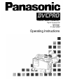
Digital Camera/VTR
AJ-
P
Operating Instructions
For your safety
’
CAUTION
RISK OF ELECTRIC SHOCK
DO NOT OPEN
FCC NOTE:
This device complies with Part 15 of the FCC
Rules. To assure continued compliance follow the
attached installation instructions and do not make
any unauthorized modifications.
CAUTION: TO REDUCE THE RISK OF ELECTRIC SHOCK,
DO NOT REMOVE COVER (OR BACK).
NO USER-SERVICEABLE PARTS INSIDE.
REFER SERVICING TO QUALIFIED SERVICE PERSONNEL.
The lightning flash with arrowhead symbol,
within an equilateral triangle, is intended to alert
the user to the presence of uninsulated “dangerous voltage ” within the product' s enclosure
that may be of sufficient magnitude to constitute
a risk of electric shock to persons.
The exclamation point within an equilateral triangle is intended to alert the user to the presence of important operating and maintenance
(service) instructions in the literature accompanying the appliance.
This equipment has been tested and found to
comply with the limits for a Class A digital device,
pursuant to Part 15 of the FCC Rules. These limits
are designed to provide reasonable protection
against harmful interference when the equipment
is operated in a commercial environment. This
equipment generates, uses, and can radiate radio
frequency energy and, if not installed and used in
accordance with the, instruction manual, may
cause harmful interference to radio communications. Operation of this equipment in a residential
area is likely to cause harmful interference in
which case the user will be required to correct the
interference at his own expense.
CAUTION:
TO REDUCE THE RISK OF FIRE OR
SHOCK HAZARD AND ANNOYING INTERFERENCE, USE THE RECOMMENDED
ACCESSORIES ONLY.
ATTENTION:
The product you have purchased is powered by a
nickel cadmium battery which is recyclable. At the
end of it ’s useful life, under various state and local
laws, it is illegal to dispose of this battery into your
municipal waste stream.
Please call 1-800-8-BATTERY for information on
how to recycle this battery.
ATTENTION:
Le produit que vous avez acheté est alimenté par
une pile au nickel-cadmium. La pile est recyclable.
Pour obtenir des renseignements sur les façons
de recycler cette pile, appeler au 1-800-8 BATTERY.
WARNING:
TO REDUCE THE RISK OF FIRE OR
SHOCK HAZARD, DO NOT EXPOSE THIS
EQUIPMENT TO RAIN OR MOISTURE.
Replace battery with part No. CR2032 only.
Use of another battery may present a risk of fire or
explosion.
Caution — Battery may explode if mistreated.
Do not recharge, disassemble or dispose of in fire.
is the safety information.
- 2 -
Contents
Safety Precautions
2
General and Features
Features of the Camera Section
Features of the VTR Section
System Configuration
5
5
8
9
Controls and Their Functions
Power Supply Section
Accessory Mounting Section
Audio Function Section
Shooting (Recording)/Playback
Function Section
Menu Operation Section
Time Code-Related Section
Warning/Status Display Section
Power Supply
Using an Anton Bauer Battery Pack
Using the Panasonic AU-BP402
Battery Pack
Using a Sony Battery Pack
Using the Sony BP-90 Battery Pack
Using an AC Power Supply (When
Using the AU-B110 AC Adaptor)
10
11
12
14
20
20
22
23
24
26
27
28
Mounting the Lens
29
Adjusting the Lens Flange
30
Adjusting the White Shading
Adjusting the Viewfinder
Adjusting the Position
Adjusting the Diopter and Screen
Adjusting the Eyecup Position
Detaching the Eyecup
Detaching and Mounting the
Viewfinder
31
Audio Input Preparations
Using the Microphone Mounted to the
Main Unit
33
34
34
35
Using the AJ-MC700P Microphone Kit
(Option) Mounted to the Main Unit
Mounting the AJ-MH700P Microphone
Holder (Option)
Using the Microphone not Mounted to
the Main Unit
Mounting a Wireless Microphone
37
38
39
41
Connecting an Audio Component
41
Mounting the Unit to a Tripod
42
Mounting the Shoulder Belt
43
Adjusting the Shoulder Pad Position
44
Attaching the Rain Cover
45
Connecting the AQ-EC1 Extension
Control Unit (Option)
46
Warning/Status Displays in the
Viewfinder and Display Window
Displaying the Setting Menu Inside the
Viewfinder
Setting Menu Configuration
Basic Setting Menu Operations
47
47
49
Lamp Displays Inside the Viewfinder
Setting the ! Lamp Display
51
52
Status Displays Inside the Viewfinder
Screen
Selecting Display Items
Display Mode and Setting Change
Message
Changing the Display Mode
Setting the Marker Displays
Setting the Camera ID
36
37
Bold letters should be set or adjusted immediately after
purchase.
- 3 -
53
56
57
58
58
59
Contents
Displays
Remaining Battery Level and Audio
Level Displays
VTR Section Operation/Status-Related
Displays
Time Code-Related Displays
Adjusting the Time and Date
60
60
61
62
Adjustments and Setup During Recording
Adjustments and Setup using the Setting
Menu
63
Setting the Gain Selector Value
64
Selecting Functions
65
Adjusting the White Balance/Black Balance
Adjusting the White Balance
66
Adjusting the Black Balance
69
Setting the Electronic Shutter
Shutter Modes
Selecting the Shutter Mode/Speed
Setting the Synchro Scan Mode
Changing the Shutter Speed/Mode
Selection Range
71
72
73
74
Changing the Iris Automatic Adjustment
Reference Value
74
Adjusting the Audio Level
75
Setting the Time Data
Setting the Time Code
Setting the User Bit
Locking the Time Code to an External
Source
External Lock Operation Procedure
Setup Card Operations
Setup Card Handling
Setup Card Data Operations
Cassettes
Inserting and Ejecting Cassettes
Preventing Accidental Erasure
77
78
79
80
81
82
87
88
Recording
Basic Procedures
Successive Shooting
89
92
Playback-Checking Recorded Contents
Rec Review
94
Color Playback
94
Connection With an External VTR
95
Recording Simultaneously with the
Internal VTR and an External VTR
96
Recording With an External VTR Instead
of the Internal VTR
Using the 26-pin Output Adapter
98
RET Button
100
Replacing the Backup Battery
101
Setting Menu Screens
102
Warning System
125
Error Codes
127
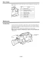
Maintenance
Condensation
Cleaning the Video Heads
Cleaning the Viewfinder
Characteristic Phenomenon of CCD
Cameras
127
128
128
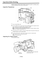
Inspections Before Shooting
Inspection Preparations
Inspecting the Camera Section
Inspecting the Viewfinder
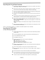
Inspecting the Iris and Zoom
Functions
Inspecting the VTR Section
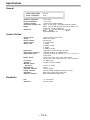
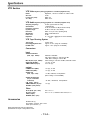
Specifications
General
Camera Section
Viewfinder
VTR Section
Accessories
Related Components
- 4 -
128
129
129
130
131
131
133
133
133
134
134
135
General and Features
The model AJ-D700 integrates a color video camera which employs three frame interline transfer
(FIT) CCDs with 410,000 device on-chip lenses with a DVCPRO format VTR which is equipped
with the latest compression technology.
The AJ-D700 is particularly compact and light weight with low power consumption, and realizes
the optimal functions and performance for an electronic news gathering (ENG) VTR-integrated
camera such as high picture quality and sensitivity, mobility, dustproofing and dampproofing, etc.
In addition, both the camera section and the VTR employ a digital signal processing system which
further improves picture quality and realizes a system for controlling setting menu and subject
data by using world standard memory cards.
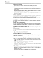
Features of the Camera Section
The camera section of the AJ-D700 has the following features.
High sensitivity: 2000 lux (F8)
High S/N ratio: 62 dB (standard)
Ultra-low smear
Ultra-low flare
Digital signal processing
Signal processing is digitized by a 14.3 MHz/28.6 MHz (typ.) 10-bit AD/DA converter. This improves picture quality, stability and reliability, and allows the viewfinder screen displays as well as
numerous adjustment and setup items to be converted to menus.
Setting menu
The setting menu is displayed on the viewfinder screen, and controls the status displays, messages, marker displays, etc. Whether or not to display each item, as well as the display conditions
when items are to be displayed, can be selected according to the user’s convenience. For example, display ON/OFF for the ! lamp display which informs the user that the unit has entered irregular status can be selected for 7 different conditions.
The setting menu is also used to select various settings and functions and execute memory card
operations, etc.
Setup cards
Setting menu and subject data can be stored on SRAM memory cards with a capacity of
64 kilobytes or greater which conform to PCM CIA standard ratings as setup cards. Stored data
can be saved individually or according to the shooting conditions, allowing the same setup conditions to be easily reproduced and assisting in standardizing setup conditions between individual
data.
High-function electronic shutter
Using the built-in electronic shutter achieves steady images even of quickly moving subjects. In
addition, the following special operation modes can also be selected.
Synchro scan mode: This mode is suited for shooting personal computer and workstation monitor screens, and provides images with little horizontal stripe noise.
High vertical resolution (Super V) mode: This mode provides images with high vertical resolution
compared to standard mode.
Wide range of video gain selections
Eleven gain values can be selected from -3 dB to +30 dB using the setting menu and the GAIN
switch. The high S/N ratio allows images with little noise to be obtained even when the gain is
increased for shooting in dark locations.
Automatic adjustment and memory functions for black balance/white balance
The black set, black balance and white balance can be automatically adjusted by simple switch
operations. Adjustment values are held in the memory even if the power for the unit is turned off,
so there is no need to readjust the balance each time the power is turned on.
There are two memory systems for white balance which can hold four adjustment values each for
the CC and ND filters, making a total of eight adjustment values. When adjustment values matching the illumination conditions are selected from among the values stored in the memory, the unit
is automatically adjusted to the corresponding white balance. (A menu setting also allows adjustment of only two values instead of the values for each filter.) In addition, when the unit is shipped
from the factory, the white balance value for 3200K is stored in the memory as a preset value. This
value can be called when there is no time to adjust the white balance, etc.
- 5 -
Features
High-performance viewfinder
The high-resolution CRT projects a detailed picture which facilitates focus operations.
The viewfinder employs a low flare CRT which makes the screen easy to see.
A center marker which indicates the center of the screen and a safety zone marker which indicates the effective screen region can be displayed by menu operations.
A large aperture allows the screen to be easily seen even when the operator’s eye is removed
from the eyepiece.
The eyepiece can easily be detached. When the eyepiece is detached, the center of the screen
will not become blurred even when viewed from a distance. This also facilitates the removal of
dust which has adhered to the CRT screen and mirror.
One-touch position adjustment is possible not only in the right-left direction but also in the
forward-backward direction.
Character display function
The unit is equipped with a function that displays switch settings, the automatic adjustment status
for black balance and white balance, warning displays, etc. on the viewfinder screen.
In addition, when using an Anton Bauer Digital Magnum series battery as the unit’s power supply,
the remaining battery level can be displayed numerically on the viewfinder screen.
Warning system for displaying the VTR section status
The unit informs of VTR trouble, the end of the tape, battery wear, etc. with various warning lamps
and a warning tone. The remaining tape time can also be checked by the character display inside
the viewfinder.
Four filter disks as standard equipment
CC (color temperature conversion) and ND (neutral density) filters are provided as standard
equipment. This allows the optimal filter setting to be selected from among four combinations in
accordance with the brightness of the subject.
Fine adjustment of the automatic iris reference value
The reference value for automatic iris adjustment can be finely adjusted by setting menu operations.
Auto close function
The unit is equipped with an auto close function which automatically closes the lens in the following cases.
When the black balance is automatically adjusted.
When the power is turned off in the auto iris mode.
Generation of SMPTE color bar and reference audio signals
The camera section contains a circuit which generates an SMPTE type color bar signal to facilitate color monitor adjustments, and a circuit which generates a reference level audio signal to
facilitate audio level adjustments.
Functions and circuits for assuring high picture quality
The AJ-D700 is equipped with the following functions (and circuits) in order to assure high picture
quality and is designed to make the fullest use of the advantages of the high-performance CCD.
A built-in AUTO KNEE circuit achieves a wide dynamic range which allows large signals to pass
through.
A built-in P-line image enhancer
A built-in shading compensation function for use with a lens extender
A built-in sawtooth wave generator for adjustments
A zebra pattern ON/OFF selector switch which selects three types of zebra patterns including
spot zebra from two levels of zebra patterns.
Audio functions
A phantom power supply type super-cardioid microphone (option) can be attached and it can
also be detached from the main unit for use in interviews.
Microphone can also be connected, and can be attached to the main unit using the AJ-MH700P
microphone holder (option).
The audio CH1 recording level can be easily adjusted at the front panel of the unit.
- 6 -
Recording by an external VTR
When an external VTR is connected using the 26-pin output adaptor (option, AJ-YA700P), recording can be performed by the external VTR instead of the internal VTR.
Remote control
Connecting the Extension Control Unit (option, AQ-EC1) allows a portion of the camera section
functions to be operated by remote control.
- 7 -
Features
Features of the VTR section
Digital system
The VTR section features a component digital recording system that employs the latest compression technology and non-compressed PCM recording for audio. This system provides superior
S/N, frequency band and waveform characteristics as well as reproduction of detailed areas, etc.,
and realizes even higher picture and sound quality.
Rec review function
This function automatically rewinds the tape and plays back the last two seconds recorded, allowing recorded contents to be quickly checked.
Playback function
Playback pictures (black-and-white pictures) can be seen on the viewfinder screen. In addition,
color playback pictures can be seen on a color monitor connected to the VIDEO OUT connector
on the main unit.
Built-in time code generator/reader
Time code information can be recorded and played back on a dedicated subcode track.
Locking of the time code to an external source
The built-in time code generator can be locked to an external generator. Also, the built-in time
code generator uses a lithium battery as its back-up power supply, allowing time codes to be
backed up for approximately one year even if power is not supplied to the unit.
Built-in DOLBY NR System*
A Dolby B Noise Reduction System is built in for audio recording in the longitudinal direction.
Successive shooting
Images can be shot successively within an accuracy of ±1 frame can be performed simply by
pressing the VTR START button or the lens VTR button.
*Dolby noise reduction manufactured under license from Dolby Laboratories Licensing Corporation.
are trademarks of Dolby Laboratories Licensing Corporation.
“Dolby” and the double-D symbol
- 8 -
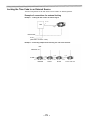
System Configuration
Microphone kit
AJ-MC700P
Wireless
microphone
receiver
WX-RA700
Shoulder
belt
26P output
adaptor
AJ-YA700P
VTR cable
VTR
Microphone holder
AJ-MH700P
Battery case
SHAN-B220
Panasonic Battery
AU-BP220
Sony Battery
NP-1
Viewfinder
Battery case
AU-M402H
Lens
(Bayonet type)
Panasonic Battery
AU-BP402
Anton Bauer Battery
Fujinon/Canon
Camera/VTR
AJ-D700
Battery case
Sony Battery
BP-90
AC adaptor
AU-B110
Rain cover
SHAN-RC700
Soft carrying
case
AJ-SC700
Cassette tape
AJ-P23MP/33MP/63MP
Tripot mount
adaptor
SHAN-TM700
Setup card
Extension control
unit
AQ-EC1
Carrying case
SHAN-B700
Multi connector
cable
SHAN-C12TCA
Time code input/
output/video input
adaptor
AJ-YA710P
- 9-
Cleaning tape
AJ-CL12MP
Battery
charger
AG-B425
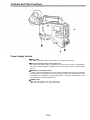
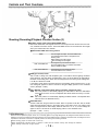
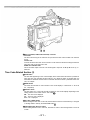
Controls and Their Functions
Power Supply Section
Battery holder
The battery pack (option) made by Anton Bauer is mounted onto this holder.
DC IN (external power input) connector (XLR, 4P)
The AU-B110 AC adaptor (option) is plugged into this socket when the unit is to be operated by
AC power. An external battery is plugged in when an external battery is to be used to operate
the unit.
BREAKER (circuit breaker) button
In order to protect the equipment, the circuit breaker is tripped and the power is automatically
turned off when an excessively high level of power flows inside. Upon completion of the internal inspection and adjustments, push this button back in. The power will come back on provided that there is no trouble inside the unit.
POWER switch
ON: Set to this position to turn on the unit’s power.
OFF: Set to this position to turn off the unit’s power.
- 1 0 -
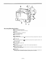
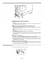
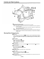
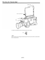
Accessory Mounting Section
Hook for mounting shoulder belt
Attach the accessory shoulder belt to this hook.
Light shoe
Mount the video light, etc. onto this shoe.
Lens mount (bayonet type)
Mount the lens here.
Lens clamping lever
Insert the lens into the lens mount
lens.
, and turn the lens mount ring using this lever to clamp the
Lens mount cap
Press up the lens clamping lever
going to be mounted.
to remove this cap. Keep the cap in place if the lens is not
Lens cable clamp
This is for clamping the lens cable.
Tripod mount
When the unit is to be secured to a tripod, mount the optional tripod attachment.
LENS connector (12-pin)
Hook up the lens connecting cable to this connector. Consult with your dealer concerning the
lens which you are going to use.
Shoulder pad
Adjust this pad to facilitate operation when carrying the unit on your shoulder. Its position can
be brought forward or backward and adjusted by loosening the two set screws.
- 1 1 -
Controls and Their Functions
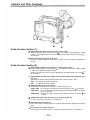
Audio Function Section (1)
AUDIO LEVEL CH1 (audio channel 1 recording level) control
When the AUDIO SELECT CH1/CH2 switch
is set to MAN, the recording level of audio
channel 1 can be adjusted by this control in addition to the AUDIO LEVEL CH1 control on
the side panel.
MIC IN (microphone input) jack (XLR, 3-pin)
Connect an optional microphone to this jack. The power for the microphone is supplied from
this jack.
Audio Function Section (2)
AUDIO LEVEL CH1/CH2 (audio channel 1/2 recording level) controls
is set to MAN, the audio level of audio channels
When the AUDIO SELECT CH1/CH2 switch
1 and 2 can be adjusted using these controls.
on
However, the audio CH1 level can also be adjusted using the AUDIO LEVEL CH1 control
the front panel.
AUDIO SELECT CH1/CH2 switch (audio channel 1/2 auto/manual level adjustment selector) switch
This selects the method used to adjust the audio levels of audio channels 1 and 2.
AUTO: For adjusting the levels automatically.
MAN:
For adjusting the levels manually.
AUDIO IN (audio input selector) switch
This selects the input signals to be recorded on audio channels 1 and 2.
FRONT [MIC]: The microphone input signals connected to the MIC IN jack are recorded.
REAR [MIC]: The microphone input signals connected to the AUDIO IN CH1/CH2 connectors are recorded.
REAR [LINE]: The line input signals connected to the AUDIO IN CH1/CH2 connectors
are
recorded.
AUDIO IN CH1/CH2 (audio input channel 1/2) connectors (XLR, 3P)
An audio component or microphone is connected here.
AUDIO OUT connector (XLR, 3P)
This is connected to an audio component. The audio channels can be selected on the setting
menu.
DC OUT (DC power output) connector
This is the DC 12 V output connector. A current of approximately 100 mA can be taken out.
- 1 2 -
—
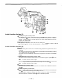
Audio Function Section (3)
ALARM (warning tone volume) control
This adjusts the warning tone volume heard from the speaker
or the earphone connected to
When it is set to the lowest position, the warning tone is not audible.
the PHONES jack
However, by making changes to the inside parts, the tone can be made audible even when the
control is at its lowest position.
MONITOR (volume) control
This adjusts the volume of the sound other than the warning tone s operation or status can also be
or earphone . When it is set to the lowest position, no sound is heard.
Audio Function Section (4)
Speaker
During recording, the EE sound can be monitored; during playback, the playback sound can be
monitored.
The warning tone is heard through the speaker in synchronization with the flashing or lighting
of the warning lamp and warning display.
The speaker sound is automatically muted when an earphone is connected to the PHONES
jack .
MONITOR SELECT (audio channel selector) switch
or earThis selects the audio channel whose sound is to be heard through the speaker
phone.
The audio channel 1 sound is output.
CH1:
CH1, 2: The sound produced by mixing the audio channel 1 and 2 sound or the stereo sound
is output. However, only the mixed sound is output from the speaker
.
CH2:
The audio channel 2 sound is output.
MONITOR (sound selector) switch
This selects the sound of the earphone when CH1, 2 is selected with the MONITOR SELECT
switch
.
PHONES (earphone) jack (mini-jack)
When an earphone (option) is connected to this jack, the sound selected by the MONITOR
switch
can be heard. The warning tones relating to the unit
heard. An earphone enabling a sufficiently high volume of sound to be heard is recommended.
sound is automatically muted.
When the earphone is connected, speaker
- 1 3 -
’
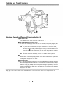
Controls and Their Functions
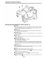
Shooting (Recording)/Playback Function Section (1)
Viewfinder
Black-and-white images can be seen in the viewfinder during recording and playback. Warnings and messages relating to the unit’s operating status and settings, zebra pattern, markers
(safety zone marker, center marker), etc. can also be seen.
PEAKING control
This is used to adjust the contours of the images inside the viewfinder to facilitate focusing. It
does not affect the camera’s output signals.
CONTRAST control
This is used to adjust the contrast of the screen inside the viewfinder. It does not affect the
camera’s output signals.
BRIGHT control
This is used to adjust the brightness of the screen inside the viewfinder. It does not affect the
camera’s output signals.
ZEBRA (zebra pattern) switch
This displays the zebra pattern inside the viewfinder.
ON: The zebra pattern is displayed.
OFF: The zebra pattern is not displayed.
When the unit is shipped from the factory, the zebra pattern is set in such a way that those
parts with an IRE video level from approx. 70% to 85% are displayed. The displaying of parts
with a level ranging from 50% to 110% or more or with a certain level can also be set on the
setting menu.
Diopter control knob
This is adjusted in such a way that the images on the viewfinder screen are seen most clearly
in accordance with the dioptric power of the camera’s operator.
Eye cup
Viewfinder forward-backward/left-right position clamp lever
in the forward-backward or left-right
Loosen this lever to adjust the position of the viewfinder
direction.
Eyecup forward-backward movement ring
Turn this ring to adjust the position of the eyecup
Viewfinder stopper screw
To detach the viewfinder
finder.
in the forward-backward direction.
from the camera, loosen this screw and then detach the view-
- 1 4 -
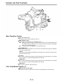
Shooting (Recording)/Playback Function Section (2)
CC/ND FILTER (filter selector) knob
This selects the filter to match the light source which is illuminating the subject.
If the setting of this knob is changed when the menu display mode has been set to “3” (default
setting), the new setting will appear for about 3 seconds on the setting change message display area of the viewfinder screen.
The knob and filter settings are
listed below.
FILTER
Description
knob setting
Examples of filter settings to
match shooting conditions
Filter
1
Shooting condition
Sunrise, sunset, inside a
studio
1
3200K
2
5600K+ 1/4ND
2
Outdoors under a clear sky
3
5600K
3
4
5600K+ 1/16ND
Outdoors under a cloudy or
rainy sky
4
Snow scenes, high
mountains, coastlines and
other extremely clear and
bright scenes
WHITE BAL (white balance memory selector) switch
PRST: Set to this position when there is no time to adjust the white balance. The white balance value for 3200K is stored in the memory.
is pressed to the AWB side, the white balance is
A or B: When the AUTO W/B BAL switch
automatically adjusted in accordance with the setting position of the filter knob
, and
the adjustment value is stored in memory A or memory B.
When the FILTER knob and the WHITE BAL switch are set to the same positions as the ones
set when the adjustment was made, the adjustment value stored in the memory is called, and
the unit is automatically adjusted to the white balance which corresponds to this value.
If the setting of this switch is changed when the menu display mode has been set to “3” (default
setting), the new setting will appear for about 3 seconds at the WHITE BAL switch display
position on the viewfinder screen. (Example: “W : A”)
- 1 5 -
Controls and Their Functions
Shooting (Recording)/Playback Function Section (3)
OUTPUT (output signal selector)/AUTO KNEE switch
This switch selects the video signals which are to be output from the camera unit to the VTR
unit, viewfinder and video monitor. The AUTO KNEE function can be used when the images
shot by the camera have been selected.
OUTPUT/AUTO KNEE switch setting positions
BARS
Color bar signals are output. The AUTO KNEE circuit
is not activated. Set the switch to this position in the
following cases:
When adjusting the video monitor
When recording color bar signals
CAM, AUTO KNEE OFF
The images shot by the camera are output.
The AUTO KNEE circuit is not activated. The default
setting is “MANUAL KNEE”.
CAM, AUTO KNEE ON
The images shot by the camera are output.
The AUTO KNEE circuit is activated.
GAIN (gain selector) switch
This is used to change the video amplifier’s gain in accordance with the lighting conditions
during shooting. The gain values corresponding to the L, M and H settings are assigned beforehand on the setting menu. When the unit is shipped from the factory, these settings are:
L=0 dB, M=9 dB and H=18 dB.
If the setting of this switch is changed when the menu display mode has been set to “3”, the
new setting will appear for about 3 seconds at the gain display position on the viewfinder
screen. (Example: “12 dB”)
AUTO W/B BAL (white balance/black balance automatic adjustment) switch
AWB: Set to this position for automatically adjusting the white balance. When the WHITE BAL
is now set to “A or B”, the adjusted value will be stored in memory A or memswitch
ory B.
ABB: Set to this position for automatically adjusting the black balance. The adjusted value
will be stored in the dedicated memory.
SHUTTER switch
Set this to ON when using the electronic shutter. When it is pressed to the SEL side, the shutter
speed and mode displays change in the ranges preset on the setting menu. If the setting of this
switch is changed when the menu display mode has been set to “2” or “3”, the new settings will
appear for about 3 seconds at the shutter display position on the viewfinder screen.
(Example: “:1/250”, “:1/61.7”)
1) AUTO KNEE function
When the level is adjusted to people, scenes, etc. for shooting against a very bright background, the background will be whited out and the
buildings or scenes in the background will become blurred. If the AUTO KNEE function is activated in cases like these, the background can be
reproduced in clear detail. This function is especially effective for shooting in the following conditions:
When shooting people in shade under a clear sky
When simultaneously shooting people in vehicles or indoor and the outdoor scenery seen through the windows
When shooting scenes with a high contrast
- 1 6 -
ECU REMOTE (remote control) connector (6-pin)
Connect the AQ-EC1 extension control unit (option) here.
<Note>
The POWER switches on unit and extension control unit must be set to OFF before the remote
control cable is connected or disconnected.
VIDEO IN connector (accessory)/26-pin output adaptor (option) mount
VIDEO IN connector (accessory) (See below for the mounting method.)
The composite video signals are supplied here. It is used for checking the return signal and
recording external input signals.
<Note>
When recording signals input from an external source, recording can only be assured for standard signals.
26-pin output adaptor (option) (See page 98 for mounting method.)
The 26-pin output adaptor AJ-YA700P (option) is mounted on this section. When the portable
VTR is connected as the external VTR, recording can be performed simultaneously with the
unit’s built-in VTR.
VIDEO OUT connector (BNC)
This outputs the video signals (75
termination, rated level) to be monitored. During recording,
EE images can be monitored; during playback, playback images can be monitored.
While performing settings on the menu, the setting menu can be superimposed onto the shot
images appearing on the monitor screen so that the settings can be checked (in which case,
the images appear in black and white).
CAM OUT (camera output) connector (BNC)
This outputs the composite video signals (75 termination, rated level). When a video monitor
is connected, the images shot by the camera can be monitored. Even while the VTR is playing
back, the camera’s images are output at all times.
Mounting the VIDEO IN connector
Remove the blank panel and mount the VIDEO IN connector.
Connect the 2P connector.
-17-
Controls and Their Functions
Shooting (Recording)/Playback Function Section (4)
VTR START button
When this pressed, recording commences; when it is pressed again, recording stops. This button has the same function as the VTR button on the lens side.
VTR SAVE/STBY (tape protection) switch
This selects the power supply status while the VTR recording is temporarily stopped (REC
PAUSE).
SAVE: This is the tape protection mode. The cylinder is stopped in the half-loading status.
Compared with the STBY position, less power is consumed and the unit can be operated longer using the battery. It takes longer for recording to commence after the VTR
START button
is pressed in the SAVE position than in the STBY position.
When the switch is set to this position, the VTR SAVE lamp inside the viewfinder
lights.
STBY: Recording commences immediately when the VTR START button is pressed.
MODE CHECK button
While this button is kept depressed, the camera’s setting status is displayed in the viewfinder. It
does not affect the camera’s output signals. This button can also be used for fine adjustment at
the setting menu during synchro scan mode.
SUPER IRIS button
This is used when backlight compensation is to be provided. When it is pressed, the switch
settings are displayed inside the viewfinder for 3 seconds. When it is pressed again, backlight
compensation is released.
Whether the super gain (30 dB) mode or the super iris (backlight compensation) mode is to
apply can be selected on the setting menu. This button can also be used for fine adjustment
during synchro scan mode.
Super gain: When 30 dB is allotted to the SUPER IRIS button, DTL and other menu settings cannot be performed for this
30 dB.
- 1 8 -
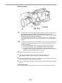
EJECT (cassette eject) button
Press this to insert or eject the cassette.
REW (rewind) button
Press this to rewind the tape. Its lamp lights during rewinding.
If this button is pressed during playback, the playback images are rewound at approximately
quadruple speed while the button is held down.
FF (fast forward) button
Press this to fast forward the tape. Its lamp lights during fast forwarding.
If this button is pressed during playback, the playback images are fast forwarded at approximately quadruple speed while the button is held down.
PLAY (playback) button
Press this to view the playback images on the viewfinder screen or color video monitor. Its
lamp lights during playback.
If this button is pressed again during playback, playback is paused and the lamp goes off. After
playback has been paused for 5 minutes, the unit automatically switches to stop status
(STOP).
STOP button
Press this to stop the tape travel.
- 1 9 -
Controls and Their Functions
Menu Operation Section
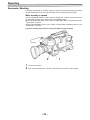
Setup card insertion slot
The optional setup cards are inserted into this slot.
MENU SET/OFF switch
This displays the setting menu on the viewfinder screen.
SET: The page on which the previous setting menu operations were completed appears on
the viewfinder screen. (When the menu is used for the first time, the first of the pages
which can be displayed appears.)
OFF: The setting menu is not displayed on the viewfinder screen,
SHIFT/ITEM button
Each time this button is pressed, the cursor moves on the setting menu page now displayed.
Use it when selecting items.
<Note>
This switch functions differently depending on the operation item. Check the function by operating the menu item by item.
UP button
This is used to increment the setting of the item selected on the setting menu by 1 level each
time it is pressed or to switch the setting between ON and OFF.
DOWN button
This is used to decrement the setting of the item selected on the setting menu by 1 level each
time it is pressed or to switch the setting between ON and OFF.
PAGE button
This is used to select the setting menu page.
Time Code-Related Section (1)
GENLOCK IN connector (BNC)
The reference signal is supplied to this connector for genlocking with the camera section.
- 2 0 -
Multi (TC IN/OUT, AUDIO OUT CH1/CH2) connector
TC IN side:
The time code serving as the reference is input when the time code is locked to an external
source.
TC OUT side:
Connect this to the time code TC IN connector on the external VTR when locking the external
VTR’s time code to this unit’s time code.
AUDIO OUT CH1/CH2 side:
This is the audio output connector. The audio signal is output at -20 dB (0 dB=0.775 V), unbalanced.
Time Code-Related Section (2)
HOLD button
The time data appearing on the counter display at the instant when this button is pressed is
held. (The time code generator will still continue to run.) When the button is pressed again, the
hold status is released. Use the button to ascertain the time at which a particular scene was
shot, for example.
RESET button
This resets the time data or user’s bit data on the counter display to “00:00:00:00” or “00 00 00
00”, respectively.
DISPLAY switch
The time code, CTL or user’s bit is made to appear on the counter display depending on the
setting positions of this switch and the TCG switch .
UB: The user’s bit is displayed.
TC: The time code is displayed.
CTL: CTL is displayed.
UP button, DOWN button
When setting the time code or user’s bit, these buttons increment or decrement by 1 the figure
of the digit made to flash by the SHIFT/ITEM button .
SHIFT/ITEM (digit advance) button
When setting the time code or user’s bit, this button is used to cause the digit which is to be set
to flash.
- 2 1 -
Controls and Their Functions
TCG (time code selector) switch
This is used to set the running mode of the internal time code generator.
F-RUN: This position is used when the time code is to be advanced continuously regardless of
the VTR’s operation.
Set to this position when aligning the time code with the actual time or locking the time
code to an external source.
SET:
This position is used for setting the time code or user’s bit.
R-RUN: This position is used when the time code is to be advanced only while recording is in
progress. The time code will be recorded continuously on a tape with a succession of
unedited shots.
Warning/Status Display Section
Tally lamp
is at HIGH or LOW, and it lights during recording by
This is activated when the TALLY switch
the VTR section. It flashes in the same way as the REC lamp inside the viewfinder to warn the
operator. The brightness when lighted can be selected using the TALLY switch (HIGH or
LOW).
TALLY switch
This controls the tally lamp .
HIGH: The tally lamp is made brighter.
OFF: The tally lamp is extinguished.
LOW: The tally lamp is made darker.
Back tally lamp
This functions in the same way as the tally lamp
when the back tally switch
is set to ON.
Back tally switch
This controls the back tally lamp .
ON: The back tally lamp operates.
OFF: The back tally lamp does not operate.
WARNING lamp
This flashes or lights when trouble occurs in the VTR section.
LIGHT switch
ON: This illuminates the display window
OFF: This extinguishes the display window illumination.
Display window
The warnings related to the VTR section, remaining battery level, sound level, time data, etc.
are displayed in this window.
- 2 2 -
Power Supply
Power can be supplied to the unit using a battery pack or AC power supply.
Using a battery pack
Anton Bauer or
Panasonic,
Sony batteries can be used for the battery pack.
Before using a battery pack, be sure to charge it completely using a battery charger.
See the Handling Instructions for the battery pack and battery charger for a detailed explanation
of charging methods.
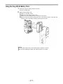
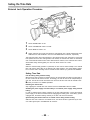
Using an Anton Bauer Battery Pack
1
Mount the battery pack.
Insert the battery pack in the direction of the arrow and then slide it into place.
Power Supply Output Connector
Control Switch
2
When detaching the battery hold down the detachment lever of the battery holder and slide
the battery pack in the direction of the arrow.
Lever
Pack
<Note>
The AJ-D700 supports the intelligent battery system and the ultra-light system.
Automatic detection can be performed for intelligent batteries with a remaining battery level of
10% or more. At this time, the remaining battery level is displayed numerically (percentage
display) inside the viewfinder. If the power is turned on with a remaining battery level of 10%
or less, the voltage is displayed. Also, after intelligent battery detection, the remaining battery
level display indicates the level for the intelligent battery even if power is supplied from an
external source.
- 2 3 -
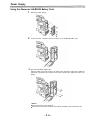
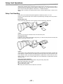
Power Supply
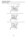
Using the Panasonic AU-BP402 Battery Pack
1
Detach the battery mounts.
2
Connect the unit’s connectors with the connectors of the AU-M402H battery case.
3
Mount the AU-M402H battery case.
Open the battery case cover and lift up the rubber cap to expose the screw holes. Tighten the
screws with a screwdriver and mount the case to the unit. Be sure to tighten the screws completely.
<Notes>
Do not pull strongly on the rubber cap.
Take care not to catch the connection cord between the battery case and the main unit.
- 2 4 -
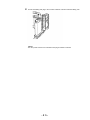
4
Connect the battery pack plug to the connector inside the case and insert the battery pack.
<Note>
The unit’s power must be set to OFF before the plug is inserted or removed.
- 2 5 -
Power Supply
Using a Sony Battery Pack
1
2
3
Remove the battery mounts.
See page 24.
Mount the accessory battery mounting connector.
Mount the Sony battery holder.
Mount the battery case with the cover detached first, and then mount the detached cover as
shown in the figure.
Tighten the mounting screws.
Tighten the power supply contact screws.
Insert the top of the detached cover in the direction of the arrow.
Align the hole at the bottom (metal part) of the cover with the hole at the bottom of the case
and mount the cover to the battery mounting connector with the screw of the battery
holder.
<Note>
Take care when attaching the battery holder that the wires are not pinched.
- 2 6 -
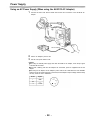
Using the Sony BP-90 Battery Pack
1 Mount the accessory battery mounting connector.
(See the preceding page.)
2
Mount the BP-90 battery case.
Tighten the mounting screws.
Tighten the power supply contact screws.
Insert the top of the detached cover in the direction of the arrow.
Align the hole at the bottom (metal part) of the cover with the bottom of the case and
mount the cover to the battery mounting connector with the screw.
<Notes>
The unit’s power must be set to OFF before the plug is inserted or removed.
Take care when attaching the battery case that the wires are not pinched.
- 2 7 -
Power Supply
Using an AC Power Supply (When using the AU-B110 AC Adaptor)
1
Connect the unit’s EXT DC IN socket with the DC OUT connector of the AU-B110 AC
adaptor.
DC IN Connector
2
3
Set the AC adaptor’s power to ON.
Set the unit’s power switch to ON.
<Notes>
When using an external power supply other than the AU-B110 AC adaptor, check the pin signal
of the EXT DC IN socket.
When both a battery pack and AC adaptor are connected, power is supplied from the AC
adaptor.
When using an AC adaptor, the AC adaptor’s power must be set to ON before the unit’s POWER
switch is set to ON. If this sequence is reversed, the AC adaptor’s output voltage will rise slowly
and may cause the unit to malfunction.
Pin No.
Signal
1
GND
2,3
4
+12V
- 28 -
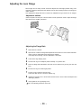
Mounting the Lens
1
Raise the lens clamping lever and remove the mount cap.
Lens Clamping Lever
Mount Cap
2
Align the indentation at the top center of the lens mount with the center mark of the lens and
mount the lens.
Mark
3
Lower the lens clamping lever and clamp the lens.
4
Press the cable into the cable clamp and connect it to the LENS connector.
LENS Connector
See the Handling Instructions provided with the lens for lens handling,
<Note>
The lens and camera adjustments listed below may be necessary depending on the lens to be
mounted.
1. Lens flanging adjustment
2. Lens auto iris adjustment
3. Lens white shading adjustment (with this unit)
- 29 -
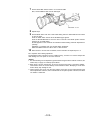
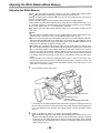
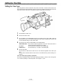
Adjusting the Lens Flange
When images are not clearly focused at both the telephoto and wide-angle positions during zoom
operations, adjust the flange back (the distance from the lens mounting surface to the image formation surface).
Once adjusted, the flange back does not need to be readjusted as long as the lens is not changed.
Adjustment method
Check the position of each part of the lens which must be operated in order to adjust the flange
back with the lens Handling Instructions.
Approx. 3 m
Adjusting the Flange Back
1
2
3
4
5
6
7
Set the lens iris to manual.
Open the iris. Position the flange back adjustment chart about 3 m from the lens and illuminate it so that an appropriate image output level is obtained.
If the image level is too high, use the CC/ND filters or the shutter.
Loosen the Ff ring clamping screw.
Set the zoom ring to the telephoto position manually or by electric drive.
Shoot the flange back adjustment chart and turn the distance ring to bring the chart into
focus.
Set the zoom ring to the wide-angle position.
Turn the Ff ring to bring the chart into focus.
At this time, take care not to move the distance ring.
8
Repeat this operation four to seven times until the lens is in focus at both the telephoto and
wide-angle positions.
9
Firmly tighten the Ff ring clamping screw.
Refer to the Operating Instructions of the lens.
- 30 -
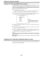
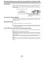
Adjusting the White Shading
The AJ-D700 is adjusted for the Fujinon S18x6.7 BERM4 (with extender) and S18X6.7 BRM4
(without extender) lenses when shipped from the factory. If a lens other than these two lenses is to
be used, adjusting the white shading before shooting is recommended. In particular, be sure to
adjust the white shading as indicated below when using a 1/2-inch camera lens without an extender (other than the S18X6.7 BRM4 noted above) or a 2/3-inch camera lens via an adaptor.
The AJ-D700 is able to adjust the white shading for vertical coloring.
(Vertical coloring refers to the condition where the top of the screen is green and the bottom is
magenta or where these colors are reversed when a white paper is shot for the entire screen.)
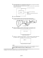
White shading adjustment procedure
1
2
Mount a lens to the camera.
Be sure to also connect the lens cable.
Set the electronic shutter to OFF and the gain to L (0 dB).
SHUTTER: OFF
3
4
GAIN: L (0 dB)
If the lens has an extender, remove the extender.
Set the MENU SET/OFF switch from OFF to SET while holding down the SHIFT/ITEM and
UP buttons to open the menu.
Press the PAGE button until the VF OPERATION page appears.
Set ZEBRA1 DETECT to 70, ZEBRA2 DETECT to 85 and ZEBRA2 to SPOT. (Initial setting
mode)
Return the MENU SET/OFF switch from SET to OFF to close the menu.
Set the viewfinder’s ZEBRA switch to ON.
MENU
PAGE
SHIFT/ITEM+UP
5
6
Shoot an evenly white paper.
Flickering occurs easily when fluorescent or mercury lamps, etc. are used for lighting.
Therefore, use a light source which does no produce flickering such as sunlight or halogen
lamps, etc.
Set the lens iris to manual and adjust the iris so that the ZEBRA pattern covers the entire
screen. If the light strikes the subject in an uneven manner, the ZEBRA pattern will not
cover a part of the screen. Therefore, adjust the position of the light source, etc. as necessary.
Check that the lens iris is between F4 to F11. If the lens iris is not within this range, adjust
the position of the light source, etc.
(Be sure to set the electronic shutter to OFF.)
- 3 1 -
7
Set the WHITE BAL selector switch to A or B execute AWB.
Next, execute ABB and then execute AWB again.
WHITE BAL: A or B
8
9
10
Repeat step 6.
Set the MENU switch from OFF to SET while holding down the SHIFT/ITEM and UP buttons
to open the menu.
Press the PAGE button until the AUTO SHADING page appears.
Press the SHIFT/ITEM button to move the arrow on the left to the WHITE position and then
press the UP or DOWN button.
ACTIVE appears on the viewfinder to indicate that white shading automatic adjustment is
operating.
Adjustment is completed when the ACTIVE display disappears.
Return the MENU switch from SET to OFF to close the menu.
When the lens to be used has an extender, insert an extender and repeat steps 6 to 9.
This completes white shading adjustment.
The adjustment value is stored in the non-volatile memory, so there is no need to readjust the
white shading even if the power for the unit is turned off.
<Notes>
1. The white shading can be adjusted for general lenses using the above method. However, this
method may not apply for extremely special lenses.
2. When using a 2/3-inch camera lens, be sure to mount the lens using a conversion adaptor.
These lenses cannot be mounted directly as their dimensions differ. Attempting to mount these
lenses directly may damage the unit.
3. Vertical coloring may occur near the open position of the lens iris even after performing the
above adjustments. However, this is characteristic of the optical system of the lens, and does
not indicate a malfunction.
- 3 2 -
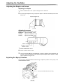
Adjusting the Viewfinder
Adjusting the Position
1
Loosen the viewfinder forward-backward/left-right position clamp lever.
Viewfinder
Lever
2
Adjust the position of the viewfinder in the forward-backward and left-right directions.
3
Tighten the viewfinder forward-backward/left-right position clamp lever to the locked position.
- 33 -
Adjusting the Viewfinder
Adjusting the Diopter and Screen
Adjusting the diopter
1
2
Set the POWER switch to ON. A picture will appear in the viewfinder.
Turn the diopter adjustment ring to adjust the diopter so that the viewfinder picture can be
clearly seen.
Diopter Adjustment Ring
Adjusting the screen
Adjust the condition of the viewfinder screen.
Brightness: Adjust the BRIGHT control
Adjust the CONTRAST control
Contrast:
Adjust the PEAKING control
Contour:
BRIGHT Control
CONTRAST Control
PEAKING Control
1
2
3
Set the POWER switch to ON.
Set the OUTPUT switch to CAM.
Turn the viewfinder BRIGHT and CONTRAST controls to adjust the picture brightness and
contrast. Turning the PEAKING control makes the picture appear softer or sharper. A sharp
picture facilitates focusing the lens.
Adjusting the Eyecup Position
Turn the eyecup forward-backward movement ring to adjust the position of the eyecup in the
forward-backward direction.
Eyecup Forward-backward Movement Ring
- 3 4 -
Detaching the Eyecup
Detaching the eyecup allows the entire screen to be seen clearly even when shooting with your
eye removed from the viewfinder. This also facilitates the removal of dust which has adhered to
the CRT screen and mirror.
<Note>
Absolutely do not wipe the mirror surface as it has been specially treated. Dust which has adhered
to the mirror should be blown away with a blower, etc.
1
2
Press the lock button.
Turn the lock ring as far as possible in the counter-clockwise direction and line up the alignment marks on the lock ring and viewfinder barrel.
Eyepiece
Alignment Marks
Lock Ring
Lock Button
3
Detach the eyecup.
Remounting the eyecup
1. Line up the alignment marks on the lock ring and the viewfinder barrel.
2. Line up the alignment mark at the tip of the eyepiece (see the illustration for step 2 above) with
the alignment marks on the lock ring and the eyecup and insert the eyecup into the barrel.
3. Turn the lock ring as far as possible in the clockwise direction and line up the lock ring’s
“LOCK” indication arrow with the alignment mark on the barrel of the viewfinder.
4. The lock button latches with a clicking sound.
“LOCK” Indication Arrow
Viewfinder Barrel
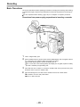
Alignment Mark
Lock Button
- 3 5 -
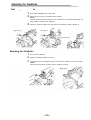
Adjusting the Viewfinder
Detaching the Viewfinder
1
2
3
Check that the POWER switch is set to OFF.
Disconnect the plug from the viewfinder cable connector.
<Note>
Use both hands to detach the viewfinder. The viewfinder may not detach smoothly with one
hand, resulting in damage to the viewfinder.
Loosen the viewfinder stopper screw and detach the viewfinder by pulling it straight up.
Pull straight up.
Stopper Screw
Hook your fingers here.
Mounting the Viewfinder
1
2
3
Press down the viewfinder.
Tighten the viewfinder stopper screw firmly.
Connect the plug to the viewfinder connector and secure the viewfinder cable with the clamp.
<Note>
Insert the plug firmly when connecting it to the viewfinder connector.
Stopper Screw
- 3 6 -
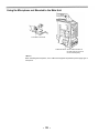
Audio Input Preparations
Using the Microphone Mounted to the Main Unit
Using the AJ-MC700P microphone kit (option) or the AJ-MH700P microphone holder (option) allows a microphone to be mounted to the main unit.
See the Handling Instructions for the microphone holder.
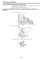
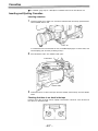
Using the AJ-MC700P Microphone Kit (Option) Microphone Mounted to the
Main Unit
1
Mount the microphone holder.
Viewfinder
Microphone Holder
2
Mount the microphone.
3
Connect the microphone connecting cable to the unit’s MIC IN jack.
MIC IN Connector
- 3 7 -
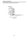
Audio Input Preparations
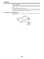
Mounting the AJ-MH700P Microphone Holder (Option)
1
Remove the microphone holder mounting screws.
2
Mount the AJ-MH700P microphone adaptor (option) to the main unit.
Mount the microphone
adaptor using the
accessory screws.
3
Mount the microphone to the microphone holder and tighten the screws.
4
Connect the microphone connecting cable to the MIC IN jack.
To the MIC IN Connector
5
Set the AUDIO IN switch to FRONT [MIC] in accordance with the audio channel to be recorded.
- 38 -
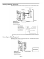
Using the Microphone not Mounted to the Main Unit
To the MIC IN Connector
AUDIO IN switch: Set the AUDIO IN switch for
the audio channel you wish to
record to FRONT [MIC].
<Note>
When extending the microphone, use a cable which supports the phantom power supply type of
microphone.
- 39 -
Audio Input Preparations
Using the Microphone not Mounted to the Main Unit
Up to two external microphones can be connected to
the AUDIO IN CH1/CH2 Connectors.
Phantom power supply type microphones can also be
supported by a menu setting.
AUDIO IN Switch: Set the AUDIO IN Switches
of the channels to which
microphones are
connected to REAR [MIC].
- 4 0 -
Mounting a Wireless Microphone
When using the Panasonic wireless microphone system, mount the WX-RA700 wireless receiver.
To the AUDIO OUT Connector
WX-RA700
Wireless Receiver
WX-R980
Camera Attachment
XLR Cable
AUDIO IN switch:
Set the AUDIO IN switch of
the channel to which the
audio signal source is
connected to REAR [LINE].
Connect to the AUDIO IN CH1
or CH2 Connector.
When detaching the
wireless microphone,
press up the lever on the
bottom of the camera
attachment (1) and detach
the microphone in the
upward direction (2).
(2)
Lever
AJ-D700 Main Unit
(1)
See the Handling Instructions for the WX-RA700 wireless receiver for wireless receiver operations.
Connecting an Audio Component
When using an audio component as the line input signal source, connect the audio component to
the unit’s AUDIO IN CH1/CH2 connectors.
Audio Equipment
AUDIO IN Switch:
Set the AUDIO IN Switch of
the channel to which the
audio signal source is
connected to REAR [LINE].
- 4 1 -
Connect to the AUDIO IN
CH1/CH2 Connectors.
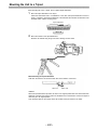
Mounting the Unit to a Tripod
When mounting the unit to a tripod, use an optional tripod attachment.
1
Mount the tripod attachment to the tripod.
Select the attachment hole in consideration of the units and tripod attachment’s center of
gravity. In addition, check that the diameter of the selected hole matches the diameter of the
universal head’s camera mounting screw.
Tripod Attachment
2
Mount the camera to the tripod attachment.
Slide the unit forward along the grooves until a clicking sound is heard.
When detaching the tripod attachment
Hold down the red lever and move the black lever in the direction of the arrow.
Red Lever
Black Lever
<Note>
When the tripod attachment pin does not return to its original position after the camera has been
detached, hold down the red lever and move the black lever in the direction of the arrow again to
return the pin to its original position.
Care should be taken as the camera cannot be mounted if the pin remains in the center.
- 4 2 -
Mounting the Shoulder Belt
Shoulder Belt
Press to open the hook.
To remove the shoulder belt, open the hooks and then remove the belt.
Press
<Note>
When mounting and removing the shoulder belt, press on the top of the hooks to check that the
belt is securely mounted.
- 4 3 -
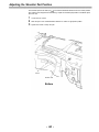
Adjusting the Shoulder Pad Position
The shoulder pad can be slid up to ” in the forward-backward direction from the center position
(the position when shipped from the factory). Adjust the shoulder pad position to facilitate operation of the unit.
1
2
3
Loosen the two screws.
Slide the pad in the forward-backward direction to select an appropriate position.
Tighten the screws to clamp the pad.
Screws
Shoulder Pad
Bottom
- 44 -
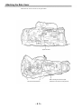
Attaching the Rain Cover
Attach the rain cover as shown in the figure below.
Tighten the Cord.
Secure the surface fastener.
- 4 5 -
When mounting the unit to the tripod
attachment, mount the unit using this hole.
Connecting the AQ-EC1 Extension Control Unit (Option)
Connecting the AQ-EC1 extension control unit (option) allows a portion of the camera section
functions to be operated by remote control.
When the AQ-EC1 is connected and the POWER switches of the unit and AQ-EC1 are set to ON,
the unit automatically enters remote control mode.
The handling instructions included with the AQ-EC1 describe operations for when the AQ-EC1 is
connected to an AQ series digital camera.
When the AQ-EC1 is connected to the AJ-D700, some functions differ, and some features cannot
be used.
6-pin Cable
ECU Connector
AQ-EC1
<Notes>
The POWER switches of the unit and AQ-EC1 must be set to OFF before the 6-pin cable is
connected or disconnected.
All adjustments and settings made using the switches and controls other than the menu setting
section of the AQ-EC1 are erased when the unit’s POWER switch is set to OFF. Also, adjustments and settings made using the AQ-EC1 cannot be written to setup cards. However, when
the AQ-EC1 is connected again, these settings return to the AQ-EC1 settings.
(Menu contents set with the menu setting section are saved.)
<Note>
The functions of the AQ-EC1 are limited as follows.
The STORE switch does not function.
(If the menu settings are changed while the AQ-EC1 is connected to the AJ-D700, the new menu
settings are saved automatically as soon as the changes are made.)
Note that the AQ-EC1 gain switch displays -3, 0 and 9 correspond to L, M and H, and the
OUTPUT switch settings CAMERA, TEST and BAR to CAM/AUTO KNEE ON, CAM/AUTO
KNEE OFF and BAR for each main unit.
The Synchro scan and Super V modes cannot be used while the AQ-EC1 is connected to the
unit.
The lens iris (IRIS) control of the AQ-EC1 is valid only when the lens iris AUTO/MANUAL selector is set to AUTO.
- 4 6 -
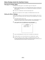
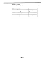
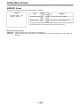
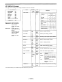
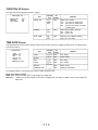
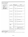
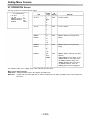
Warning/Status Displays in the Viewfinder and Display Window
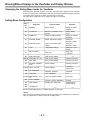
Displaying the Setting Menu Inside the Viewfinder
When the MENU SET/OFF switch is set to SET, the setting menu appears on the viewfinder
screen. The setting menu is displayed in page units. The following table lists all pages contained
in the setting menu as well as an outline of the functions for each page.
The setting menu configuration can be changed according to the purpose.
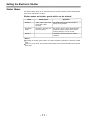
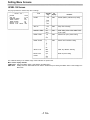
Setting Menu Configuration
Page
No.
Page name
Reference
Function outline
58
MARKER
Marker settings
Setting the Marker
Displays
56
VF DISPLAY
Selection of viewfinder screen
displays
Setting Display
Items
59
CAMERA ID
Camera ID display settings
Setting the Camera
ID Display
72
SHUTTER SPEED
Shutter speed/mode settings
Setting the
Electronic Shutter
73
SYNCHRO SCAN
Synchro scan shutter speed
settings
Setting the
Electronic Shutter
52
! LED
! lamp display settings
Setting the ! Lamp
Display
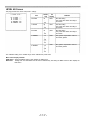
81
SET UP CARD
Setup card
Setup card
operations
107
MAIN FUNCTION
Used function settings
108-110 FUNCTION 1/5 to 5/5
Used function settings
Selecting Functions
62
TIME DATE
Time and date settings
Selecting Functions
64
SETTING LOW/MID/
HIGH
Camera settings
Selecting Functions
Camera settings
Recording
Adjustments
Viewfinder operations
Viewfinder
Lens adjustments
Lens
User menu ON/OFF settings
User Menu
115-119 LEVEL 1/6 to 6/6
120
121
121-123
VF OPERATION
LENS ADJ
MENU SELECT 1/3 to
3/3
124
AUTO SHADING
Automatic shading adjustments
Shading
50
124
DATA RESET
Resetting the setting menu
Returning to the
default settings
124
DIAGNOSTIC
See the corresponding pages for a detailed description of each page
<Note>
When connecting the AQ-EC1 extension control unit (option) and controlling the AJ-D700 externally, the engineer menu is always opened as the setting menu.
- 4 7-
Warning/Status Displays in the Viewfinder and Display Window
Changing the setting menu configuration
The setting menu can be configured by selecting only the pages necessary for the application.
Pages are selected using the MENU SELECT page of the engineer menu mode.
When using the engineer menu, switch the unit to engineer mode as described below.
The unit is switched to user mode by setting the MENU SET/OFF switch to “SET”.
The unit is switched to engineer mode by holding down the SHIFT/ITEM and UP buttons simultaneously and setting the MENU SET/OFF switch to SET.
The user and engineer modes differ as follows.
Only the selected pages the setting menu can be used. The data set on each
User mode:
page is written to the non-volatile memory, allowing it to be stored for extended
periods of time.
Engineer mode: All pages contained in the setting menu can be used. In addition, the data set at
each page is written to the non-volatile memory, allowing it to be stored for extended periods of time.
After completing the adjustments and settings with engineer mode, configuring a menu consisting
only of frequently used pages allows the necessary pages to be called quickly.
- 48 -
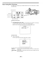
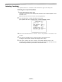
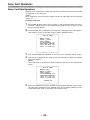
Basic Setting Menu Operations
The setting menu is operated using the MENU SET/OFF switch and the SHIFT/ITEM, UP, DOWN
and PAGE buttons.
SHIFT/ITEM Switch
UP Button
DOWN Button
PAGE Button
MENU SET/OFF Switch
Displaying the setting menu
1
Set the MENU SET/OFF switch to SET.
The status displays at the top and bottom of the viewfinder screen disappear, and the page
on which the previous setting menu operations were completed appears.
When the menu is used for the first time, the first of the selected pages appears.
- MARKER CENTER MARK : ON
SAFETY ZONE : 1
Changing the page
1
Press the PAGE button.
The menu page changes each time the PAGE button is pressed.
- ! LED *GAIN(0dB)
·GAIN(-3dB)
*SHUTTER
·WHITE PRESET
*EXTENDER
·FILTER
·SUPER V
The page can also be changed using the UP and DOWN buttons as follows.
The menu page is incremented continuously while the UP and PAGE buttons
PAGE+UP:
are held down.
PAGE+DOWN: The menu page is decremented continuously while the DOWN and PAGE
buttons are held down.
- 49 -
Warning/Status Displays in the Viewfinder and Display Window
Selecting the desired item
1
Press the SHIFT/ITEM switch.
Each time this button is pressed, the cursor (arrow) which indicates the selected item moves
to the next item.
– MARKER –
Cursor
Movement order
CENTER MARK : ON
SAFETY ZONE : 1
The item can also be selected using the UP and DOWN buttons as follows.
Changing the settings
Press the UP button to increase the setting.
The setting is incremented by 1 level each time
the UP button is pressed.
Press the DOWN button to decrease the setting.
The setting is decremented by 1 level each time
the DOWN button is pressed.
Changing the ON/OFF selection
The setting switches to ON or OFF each time the UP (or DOWN) button is pressed.
Returning to the default settings
The unit can be returned to the default settings (the settings when shipped from the factory or the
engineer mode settings) by pressing the UP (or DOWN) button at the DATA RESET page of engineer mode*.
However, care should be taken as the flare and shading adjustment values cannot be returned to
the default settings.
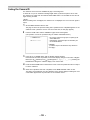
Quitting the menu
Set the MENU SET/OFF switch to OFF.
The setting menu disappears from the viewfinder screen and the displays indicating the units
current status appear at the top and bottom of the viewfinder screen.
*Engineer mode
The menu for this mode is opened by holding down the SHIFT/ITEM and UP buttons simultaneously and then setting the MENU SET/OFF switch to the “SET” position.
- 50 -
Lamp Displays Inside the Viewfinder
The viewfinder displays are as follows.
VTR SAVE
1. REC (recording) lamp
This lamp lights (red) during recording, and flashes when warnings are issued.
See “Warning System” (page 125) for a detailed description.
2. BATT (battery) lamp
When the battery voltage has dropped, this lamp begins flashing several minutes before the
unit can no longer be operated, and lights when the unit can no longer be operated.
To prevent operation from being interrupted, exchange the battery quickly before the battery
runs out.
3. ! (irregular operation status warning) lamp
This lamp lights when the unit enters irregular operation status for any of the items set to ON at
the ! LED page of the setting menu. Applicable items are as follows.
Setting contents
Setting item
Gain (0 dB)
The gain is set to a value other
than 0 dB.
Gain (–3 dB)
The gain is set to a value other
than –3 dB.
SHUTTER switch
The switch is set to ON.
WHITE PRESET switch
The switch is set to PRESET.
Lens extender
The lens extender is being used.
Filter control
The control is set to a value other
than 1.
SUPER V switch
The switch is set to ON.
See “Setting the ! Lamp Display” (next page) for selecting ! lamp display items.
4. VTR SAVE (VTR power saving) lamp
This lamp lights when the VTR SAVE/STBY switch is set to SAVE. It is not lighted during recording.
<Note>
Regardless of the VTR SAVE/STBY switch, the unit automatically enters the SAVE state and the
lamp lights either after two minutes when in the stopped state, or after the length of time set for the
pause timer (the pause time) when in the paused state.
- 5 1 -
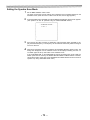
Lamp Displays Inside the Viewfinder
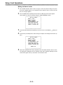
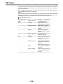
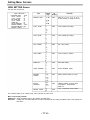
Setting the ! Lamp Display
Items subject to ! lamp display are selected at the ! LED page of the setting menu. (When shipped
from the factory, the unit is set so that the ! LED page is not displayed.) To operate the ! LED page,
switch the unit to engineer mode or select the ! LED page at the MENU SELECT page.
See “Setting Menu Configuration” (page 47) for engineer mode and selection of displayed
pages.
.
1
2
Set the MENU SET/OFF switch to SET.
The setting status displays disappear from the viewfinder screen, and the page on which the
previous setting menu operations were completed appears. (When the menu is used for the
first time, the first page appears.)
Press the PAGE button until the ! LED page shown below appears. (This operation can also
be performed using the PAGE+ UP/DOWN buttons.)
-
!LED
-
*GAIN(0dB)
·GAIN(-3dB)
*SHUTTER
·WHITE PRESET
*EXTENDER
·FILTER
·SUPER V
*GAIN (0 dB):
·GAIN (-3 dB):
*SHUTTER:
·WHITE PRESET:
* EXTENDER:
·FILTER:
·SUPER V:
3
4
<Note>
*: ON
·: OFF
This selects whether or not the ! lamp lights when the gain is set to
any value other than 0 dB.
This selects whether or not the ! lamp lights when the gain is set to
any value other than -3 dB.
This selects whether or not the ! lamp lights when the SHUTTER
switch is set to ON.
This selects whether or not the ! lamp lights when the white balance
memory channel is PRST.
This selects whether or not the ! lamp lights when the lens is in EXTENDER mode.
This selects whether or not the ! lamp lights when the filter is set to
any value other than 3200K.
This selects whether or not the ! lamp lights when SUPER V is set to
ON.
Repeatedly press the SHIFT/ITEM button to move the cursor to the position of the desired
item.
Press the UP and DOWN buttons to choose ! lamp lighted/not lighted for the selected item.
To select ON: Press the UP button. An asterix (*) appears to the left of the item name.
To select OFF: Press the DOWN button. A period (·) appears to the left of the item name.
Repeat steps 3 and 4 to continue making ON/OFF settings for other items.
5
When menu operations have been completed, set the MENU SET/OFF switch to OFF.
The setting menu disappears from the viewfinder screen and the displays indicating the unit’s
current status appear at the top and bottom of the viewfinder screen.
- 52 -
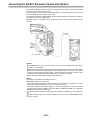
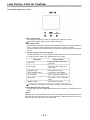
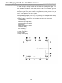
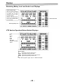
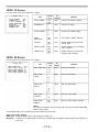
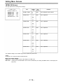
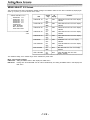
Status Displays Inside the Viewfinder Screen
In addition to images, messages indicating the unit’s settings and operating status appear on the
viewfinder screen, The center marker and safety zone marker, etc. are also displayed.
When the MENU SET/OFF switch is set to OFF, items set to SET at the VF DISPLAY page of the
setting menu and using related switches appear at the top and bottom of the screen.
Messages informing of the setting contents or of the adjustment course or results can also be
displayed for approximately 3 seconds when settings are changed, during the course of adjustments, or after adjustments have been completed.
See “Selecting Display Items” (page 56) for selecting display items, “Display Mode and Setting
Change Message” (page 57) for the setting change message, and “Setting the Marker Displays”
(page 58) for the marker displays.
The display positions of all items which can be displayed are shown in the figure below.
1. Extender display
2. Shutter speed/mode display
3. Remaining tape length display
4. Remaining battery level display
5. Filter display
6. White balance memory display
7. Gain value display
8. Audio level display
9. Iris value display
10. Warning display
11. Safety zone marker
12. Center marker
13. Super iris ON display
EX OFF
1
W:A
- 53 -
S
0dB
F-60
14.6V
F5.6
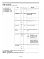
Status Displays Inside the Viewfinder Screen
1
2
3
Extender display
This is displayed when the lens extender is being used.
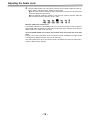
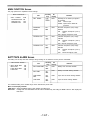
Shutter speed/mode display
This displays the shutter speed or shutter mode setting.
The shutter is not used.
OFF:
1/100, 1/120, 1/250, 1/500, 1/1000, 1/2000:
Shutter speeds (seconds) during standard mode.
1/30.4–1/250 (SYNCHRO SCAN):
Synchro scan mode is selected.
High vertical resolution mode is selected.
SUPER V:
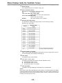
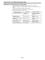
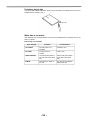
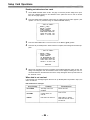
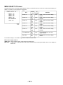
Remaining tape length display
This indicates the remaining tape length (minutes) for the VTR during recording.
Remaining tape length display
Display
4
5
6
7
Remaining tape
length
F–60
Full to 60 minutes
60–55
60 to 55 minutes
55–50
55 to 50 minutes
50–45
50 to 45 minutes
45–40
45 to 40 minutes
40–35
40 to 35 minutes
35–30
35 to 30 minutes
30–25
30 to 25 minutes
25–20
25 to 20 minutes
20–15
20 to 15 minutes
15–10
15 to 10 minutes
10–5
10 to 5 minutes
5–0
5 to 0 minutes
The “5–0” display flashes when there is
less than 3 minutes of tape remaining.
Remaining battery level display
When an Anton Bauer Digital Magnum Series battery is used to supply power to the unit,
the remaining battery level is displayed numerically (%).
Filter display
This displays the type of filter selected.
White balance memory display
This displays the selected white balance automatic adjustment memory.
A: The WHITE BAL switch is set to A.
B: The WHITE BAL switch is set to B.
P: The WHITE BAL switch is set to PRST.
Gain value display
This displays the image amplifier gain setting (dB) set by the GAIN switch.
<Note>
When using an Anton Bauer Digital Magnum Series battery, the remaining battery level display
continues to display the level for the Anton Bauer battery even if power supply is switched to an
external power source near the end of the battery’s power. However, note that the unit operates
according to the external power source.
- 54 -
8
Audio level display
This displays the audio CH1 level.
During sine wave input, the audio level display corresponds roughly to the VTR level meter
display as follows.
Audio Channel 1 Level Display
VTR Level Meter
9
10
11
12
13
-40 -30 -25 -20 -15 -8 0
Iris value display
This displays the approximate iris setting (F number).
Warning display
This displays the black balance, white balance, auto knee function, super iris, super high
gain and other warning displays.
Safety zone marker
This indicates the 80% or 90% (setting when shipped from the factory) range for the viewfinder screen area. The screen area percentage is selected at the MARKER page of the
setting menu.
See “Setting the Marker Displays” (page 58) for a detailed description.
Center marker
This indicates the center of the viewfinder screen. This marker is displayed when set to ON
at the MARKER page of the setting menu.
Super iris ON display
This indicates that the super iris is ON.
1) Iris value display
The iris value is displayed when using a lens with the iris value display function.
- 5 5 -
Status Displays Inside the Viewfinder Screen
Selecting Display Items
The items to be displayed on the viewfinder screen can be selected by switching the display ON/
OFF setting independently for each item at the VF DISPLAY page. The items which can be selected are as follows,
Display mode (See “Display Mode and Setting Change/Adjustment Course Message”.)
Extender display
Shutter speed/mode display
Remaining tape length display
Remaining battery level display
Filter display
White balance memory display
Gain value display
Level meter display
Iris value/super iris ON status display
Camera ID display
The camera ID is displayed when recording the color bar according to the OUTPUT/AUTO
KNEE switch setting. See “Setting the Camera ID” (page 59) for a detailed description.
Select the items to be displayed on the viewfinder screen.
1
2
Set the MENU SET/OFF switch to SET.
The page on which. the previous setting menu operations were completed appears on the
viewfinder screen. (When the menu is used for the first time, the first page appears,)
Press the PAGE button until the VF DISPLAY page shown below appears.
(This operation can also be performed using the PAGE+UP/DOWN function.)
Display mode
Extender display
Shutter speed/mode display
Remaining tape length display
Remaining battery level display
Filter display
White balance memory display
Gain value display
Level meter display
Iris value/super iris ON status display
Camera ID display
3
4
5
– VF DISPLAY –
:3
DISP MODE
:ON
EXTENDER
SHUTTER
:ON
:ON
TAPE
:ON
BATTERY
:ON
FILTER
:ON
WHITE
:ON
GAIN
LEVEL METER:ON
:S+IRIS
IRIS
:ON
CAMERA ID
Press the SHIFT/ITEM button to move the cursor to the position of the desired item.
Press the UP and DOWN buttons to choose whether to display (ON) or not display (OFF) the
selected item on the viewfinder screen.
The setting switches to ON or OFF each time the UP (or DOWN) button is pressed.
Repeat steps 3 and 4 when setting display ON/OFF for other items.
When menu operations have been completed, set the MENU SET/OFF switch to OFF.
The setting menu disappears from the viewfinder screen and the displays indicating the settings of the selected items appear.
- 5 6 -
Display Mode and Setting Change Message
Messages informing of the contents of changed settings and adjustment results can be limited to
part of the displayed items or not displayed for all items.
The conditions under which messages are displayed and the corresponding display modes are
shown in the table below.
Setting change/adjustment results messages and display modes
Conditions under which
messages are displayed
Display mode
setting
Message
1
When the filter selection is
changed.
ND: n (n=1, 2, 3, 4)
When the gain setting is
changed.
GAIN: n dB (n=–3, 0, 3, 6, 9, 12, 15, 18,
21, 24, 30)
When the WHITE BAL switch
setting is changed.
WHITE: n (n=ACH, BCH, PRESET)
When the OUTPUT/AUTO
KNEE switch is set to AUTO
KNEE or OFF*)
AUTO KNEE: ON (or OFF)
When the shutter speed/mode
setting is changed.
SS: 1/100 (or 1/120, 1/250, 1/500,
1/1000, 1/2000, S. SCAN, SUPER V)
When the white balance is
adjusted (AWB)
Ex.) AWB: OK
See “Adjusting the White Balance”
(page 66) for a detailed description.
When the black balance is
adjusted (ABB)
Ex.) ABB: OK
See “Adjusting the Black Balance”
(page 69) for a detailed description.
2
3
: Message displayed
: Message not displayed
*) The message is displayed for approximately 3 seconds immediately after the power for the unit is turned
on.
- 5 7 -
Status Displays Inside the Viewfinder Screen
Changing the Display Mode
The display mode setting appears on the VF DISPLAY page of the setting menu.
1
2
3
Perform the operations in steps 1 to 3 of “Selecting Display Items” (page 56) to display the VF
DISPLAY page of the setting menu on the viewfinder screen and align the cursor with the
DISP MODE item.
Press the UP or DOWN button to select the desired display mode.
When menu operations have been completed, set the MENU SET/OFF switch to OFF.
Setting the Marker Displays
Display ON/OFF switching for the center and safety zone markers and selection of 80% or 90% of
the screen area as the safety marker range are performed at the MARKER page of the setting
menu.
1
2
Set the MENU SET/OFF switch to SET.
The page on which the previous setting menu operations were completed appears on the
viewfinder screen. (When the menu is used for the first time, the first page appears.)
Press the PAGE button until the MARKER page shown below appears.
(This operation can also be performed using the PAGE+UP/DOWN function.)
– MARKER –
CENTER MARK : ON
SAFETY ZONE : 1
3
4
5
Press the SHIFT/ITEM button to move the cursor to the position of the desired item.
The setting switches to ON or OFF each time the UP (or DOWN) button is pressed.
When menu operations have been completed, set the MENU SET/OFF switch to OFF.
The setting menu disappears from the viewfinder screen and the displays indicating the units
current status appear at the top and bottom of the viewfinder screen.
- 58 -
Setting the Camera ID
The camera ID can be set at the CAMERA ID page of the setting menu.
A camera ID of up to ten characters including English letters, symbols and spaces can be used.
The camera ID is output when the OUTPUT/AUTO KNEE switch is set to BARS and the color bar
signal is being recorded.
<Note>
When the setting menu is displayed, the camera ID is not displayed even if the color bar signal is
output.
1
2
Set the MENU SET/OFF switch to SET.
The page on which the previous setting menu operations were completed appears on the
viewfinder screen. (When the menu is used for the first time, the first page appears.)
Press the PAGE button until the CAMERA ID page shown below appears.
(This operation can also be performed using the PAGE+ UP/DOWN function.)
– CAMERA ID –
ID:**********
: The cursor is moved to the right (max. 10 spaces) by the
SHIFT/ITEM button.
: English letters, symbols and space are switched by the
UP and DOWN buttons.
Camera ID
("*" indicates a space. This indication is only used at this
menu page.)
3
4
5
Press the UP (or DOWN) button until the desired character appears.
Each time the UP button is pressed, the character display changes in the order of English
letters (A to Z) numbers (0 to 9)
symbols [space, >, <, ), (, ‘, ‘, --, _, ~, /, !]. Pressing the
DOWN button changes the character display in the reverse order.
Press the SHIFT/ITEM button to advance the cursor to the next position and return to step 3
to set the characters.
When menu operations have been completed, set the MENU SET/OFF switch to OFF.
The setting menu disappears from the viewfinder screen and the displays indicating the unit’s
current status appear at the top and bottom of the viewfinder screen.
- 59 -
Displays
Remaining Battery Level and Audio Level Displays
Remaining tape length
When the amount remaining
on the tape is more than
30 minutes long, all seven
segments up to the "F" position appear lighted.
When it is less than 30 minutes long, one segment will go
off for every 5-minute reduction in the length.
Audio CH level meter
Remaining battery level
VTR Section Operation/Status-Related Displays
Lights
DF
SLAVE
TCG
HOLD
WIDE
Error code:
Indicated in the display
window.
Warning
RF:
SERVO:
HUMID:
SLACK:
display
Lights when video head clogging occurs.
Lights when the servo is out of order.
Lights when condensation occurs on the head drum.
Lights when tape wind-up trouble occurs.
See “Warning System” (page 125) for a detailed description.
- 60 -
Time Code-Related Displays
These lamps light to indicate the time code, CTL and real time displays.
This lamp lights during drop frame mode
DF:
SLAVE: This lamp lights when the time code is locked to an external source.
HOLD: This lamp lights when the time code generator is held (when the HOLD button is pressed).
Time counter display: This displays the time code, CTL, user bit and real time.
See below for the relationship between displayed items and switch settings.
Relationship between the TCG and DISPLAY switch setting positions and the time counter
display
The item displayed in the time counter display is determined by the TCG switch and DISPLAY
switch settings.
Time code-related switch settings and display items
DISPLAY switch
position
TCG switch
position
SET
F-RUN or R-RUN
Displayed item
TC or CTL
Time code
UB
User bit
CTL
CTL
TC
Time code
UB
User bit
- 6 1 -
Adjusting the Time and Date
Adjustment and setup using the setting menu
1. Hold down the SHIFT/ITEM and UP buttons and set the MENU SET/OFF switch to SET. The
unit switches to ENG mode.
The page on which the previous setting menu operations were completed appears on the
viewfinder screen.
(When the menu is used for the first time, the first page appears.)
2. Press the PAGE button until the TIME/DATE page shown below appears.
(This operation can also be performed using the PAGE+UP/DOWN function.)
– TIME/DATE –
YEAR
:95
MONTH :01
: 01
DAY
HOUR
:00
MINUTE:00
TIME/DATE SET
3. Press the SHIFT/ITEM button to select the item to be changed.
4. Press the UP (or DOWN) button to change the setting value.
The number is incremented by +1 each time the UP button is pressed and decremented by –1
each time the DOWN button is pressed.
– TIME/DATE –
YEAR
: 95
MONTH :01
: 01
DAY
HOUR
:00
MINUTE:00
TIME/DATE SET
5. When the settings have been completed, press the SHIFT/ITEM button to select TIME/DATE
SET and then press the UP (or DOWN) button. The time starts from when the button is
pressed.
TIME/DATE SET
6. When menu operations have been completed, set the MENU SET/OFF switch to OFF.
The setting menu disappears from the viewfinder screen and the displays indicating the unit’s
current status appear at the top and bottom of the viewfinder screen.
<Note>
The seconds cannot be set and always stat-t from 0 seconds.
- 62 -
Adjustments and Setup During Recording
Adjustments and Setup Using the Setting Menu
Adjustments and setup operations during recording are performed at the setting menu.
Setting menu operations are basically performed according to the procedures described on
page 49.
However, these procedures vary slightly according to the item.
Items which can be adjusted or set up at the setting menu are as follows.
Adjustment/setup items at the setting menu
Page name
Adjustment/setup item
Operation reference
Setting the gain selector value
SETTING
(LOW/MID/HIGH)
Setting the Gain Selector
Value, Setting the DTL and
gamma, etc.
Selecting the shutter
speed/mode to be used
SHUTTER SPEED
Setting the Electronic
Shutter
Setting the synchro scan mode
shutter speed
SYNCHRO SCAN
Setting the Electronic
Shutter
Selecting required functions
FUNCTION 1/5 to 5/5
Selecting Functions
Shading adjustment
AUTO SHADING
Shading Adjustment
Setup card data operations
SET UP CARD
Setup Card Operations
- 63 -
Adjustments and Setup During Recording
Setting the Gain Selector Value
When shooting in locations without sufficient brightness, bright images can be obtained by raising
the gain. However, care should be taken as raising the gain also increases the noise.
The gain value for the image amplifier is selected by the GAIN switch. The gain values corresponding to the L, M and H positions of the GAIN switch are set at the MASTER GAIN page of the
setting menu.
Setting the gain selector value
1
2
Set the MENU SET/OFF switch to SET.
The page on which the previous setting menu operations were completed appears on the
viewfinder screen.
(When the menu is used for the first time, the first page appears.)
Press the PAGE button to display the SETTING (LOW/MID/HIGH) page shown below.
(This operation can also be performed using the PAGE+ UP/DOWN function.)
– LOW SETTING –
: 0dB
MASTER GAIN
: 13
H.DTL LEVEL
: 10
V.DTL LEVEL
: 08
DTL CORING
: 03
H.DTL FREQ.
: 00
DARK DTL
LEVEL DEPEND :03
MASTER GAMMA :0.60
BLACK STRETCH:OFF
MATRIX TABLE :A
3
4
5
Press the SHIFT/ITEM button repeatedly to move the cursor to the MASTER GAIN position.
Press the UP or DOWN button to set the gain value.
The gain value can be set freely regardless of size from among -3, 0, 3, 6, 9, 12, 15, 18, 21,
24 and 30 dB.
When resetting the gain values to the settings when shipped from the factory (LOW=0 dB,
MID=9 dB, HIGH=18 dB), select MENU INIT. at the DATA RESET page of the setting menu
and press the UP or DOWN button.
When menu operations have been completed, set the MENU SET/OFF switch to OFF.
The setting menu disappears from the viewfinder screen and the displays indicating the unit’s
current status appear at the top and bottom of the viewfinder screen.
- 6 4 -
Selecting Functions
VTR operation functions can be selected at the FUNCTION 3/5 page of the setting menu.
Selecting the required functions
1
2
Set the MENU SET/OFF switch to SET.
The page on which the previous setting menu operations were completed appears on the
viewfinder screen.
(When the menu is used for the first time, the first page appears.)
Press the PAGE button to display the FUNCTION 3/5 page.
(This operation can also be performed using the PAGE+UP/DOWN function.)
– FUNCTION 3/5 –
HUMID OPE
26P CONTROL
REC START
TC MODE
UB MODE
PAUSE TIMER
BATTERY SEL
TCG VF DISP
3
4
5
:OFF
:OFF
: NORMAL
:DF
: USER
:30
:NiCd–12
:OFF
Press the SHIFT/ITEM button to move the cursor to the position of the function to be
changed.
Press the UP (or DOWN) button to change the setting of the selected function.
If settings for other functions are also to be changed, return to step 3.
When menu operations have been completed, set the MENU SET/OFF switch to OFF.
The setting menu disappears from the viewfinder screen and the displays indicating the unit’s
current status appear at the top and bottom of the viewfinder screen.
- 6 5 -
Adjusting the White Balance/Black Balance
Adjusting the White Balance
Adjusting the white balance and black balance in the order of AWB (white balance adjustment) ABB (black balance adjustment AWB will provide a better picture.
Normally, the white balance and black balance do not need to be readjusted even if the power is
turned off and then on again.
However, the white balance must be readjusted when the lighting conditions change.
If black balance and white balance adjustments are started when the display mode is set to “2” or
“3”, messages informing of the adjustment course and results will appear on the viewfinder
screen. Set the display mode to “1” to not display these messages.
See “Display Mode and Setting Change Message” (page 57) for a description of setting the display mode.
<Notes>
The white balance and black balance cannot be adjusted while the setting menu appears on the
viewfinder screen. Therefore, be sure to set the MENU SET/OFF switch to OFF.
ABB must be executed again when the MASTER GAIN values on the LOW SETTING, MID SETTING and HIGH SETTING pages of the setting menu are changed, the S IRIS SW item is set to
+30 dB at the FUNCTION 2/5 page of the setting menu, or the GAMMA (ON/OFF) item is
switched at the FUNCTION 1/5 page of the setting menu.
With artificial lights, particularly with fluorescent lights and mercury-arc lamps, the strength of the
R, G and B colors changes in synchronization with the power line frequency even if the brightness of these lights appears to be constant. Especially in areas where the power line frequency
is 50 Hz, the vertical synchronizing frequency (approx. 60 Hz) of the TV and the frequency
(50 Hz) of the lighting tend to interact. This gives rise to flicker and to a phenomenon where the
hue changes along with the passage of time, and it is it impossible to obtain the proper white
balance.
These phenomena can be reduced by setting the shutter speed to 1/100. For this reason, wherever the unit is used under fluorescent or mercury-arc lamps and at a frequency of 50 Hz, the
shutter speed must be set to 1/100 and the white balance obtained. This shutter speed of 1/100
should also be used during shooting.
1
Set the switches as shown in the figure.
MENU SET/OFF: OFF
FILTER knob
WHITE BAL: A or B
OUTPUT: CAM
GAIN: Set the smallest gain value possible.
If the settings of the GAIN and WHITE BAL switches are changed, a message informing of
the new setting will appear for about 3 seconds at the setting change message display position on the viewfinder screen. (However, the message appears only when the display mode is
set to "3".)
2
Select the FILTER knob setting in accordance with the lighting conditions.
See FILTER knob (page 15) in the Shooting (Recording)/Playback Function Section for examples of FILTER knob settings. If the setting of the FILTER knob is changed, a message
informing of the new setting will appear for about 3 seconds at the setting change message
display position on the viewfinder screen. (However, the message appears only when the
display mode is set to “3”.)
- 66 -
3
Place the white pattern over a location with the same conditions as the light source illuminating the subject and zoom up to project white on the screen.
A white object (white cloth, white wall) near the subject can also be used. The white area
required is as shown below.
1/4 or more of the screen width
1/4 or more of the screen height
<Note>
Take care not to allow high-intensity spots to
enter the screen.
White cloth
4
5
Adjust the iris of the lens.
Press the AUTO W/B BAL switch to the WHT side and release the switch.
The switch returns to the center and the white balance is automatically adjusted.
AUTO W/B BAL switch
6
During the adjustment, the following message appears on the viewfinder screen.
(However, the message appears only when the display mode is set to “2” or “3”.)
AWB ACTIVE
Message during adjustment
7
Adjustment is completed after approximately 1 second (the following message appears) and
the adjustment value is automatically stored in the memory (A or B) selected in step 1.
AWB OK
Message after adjustment is completed
<Note>
If a lens equipped with the automatic iris function is used, the iris may experience hunting1). In
these cases, adjust the iris gain knob (the knob marked IG, IS, S, etc.) on the lens.
See the Handling Instructions for the lens for a detailed description.
1) Hunting: The auto iris responds repeatedly causing the image to become darker and brighter.
- 6 7 -
Adjusting the White Balance/Black Balance
When the White Balance Cannot be Automatically Adjusted
An error message will appear on the viewfinder screen.
(The message appears when the display mode is set to “2” or “3”.)
The displayed messages are as follows.
Error messages related to white balance adjustment
Treatment
Meaning
Error message
COLOR TEMP. HIGH
The color temperature is too
high.
Select an appropriate filter.
COLOR TEMP. LOW
The color temperature is too
low.
Select an appropriate filter.
LOW LIGHT
There is insufficient
illumination.
Increase the illumination or
gain.
LEVEL OVER
There is too much illumination.
Decrease the illumination or
gain.
If the above error messages appear, carry out the respective treatment attempt to adjust the white
balance again.
If the error message continues to appear even after repeated attempts, consult your dealer.
<Note>
The white balance cannot be adjusted while the setting menu is displayed on the viewfinder
screen. Therefore, be sure to set the MENU SET/OFF switch to OFF.
When there is no Time to Adjust the White Balance
Set the WHITE BAL switch to PRST.
The white balance for the filter is automatically adjusted according to the setting position of the
FILTER knob (outside).
White balance memories
The white balance has two memory systems: A and B.
Adjustment values for each filter can automatically be stored in the memory corresponding to the
setting (A or B) of the WHITE BAL switch. The unit contains 4 filters, making a total of 8 (4X2)
adjustment values which can be stored.
If FILTER INH on the FUNCTION 2/5 page of the setting menu is set to ON, the A and B systems
can be limited to one memory each.
In this case, the memory contents are not linked to the filters.
- 6 8 -
The black balance must be adjusted in the following cases.
When the unit is used for the first time
When the unit is first used after an extended period of non-use
When the unit is used under conditions where the ambient temperature has changed by a wide
margin
When the gain selector value is changed
When the SUPER IRIS button setting is changed (when setting is changed to +30 dB)
When the gamma ON/OFF is changed
Adjusting the Black Balance
1
Set the switches as shown in the figure.
MENU SET/OFF: OFF
OUTPUT: CAM
2
Press the AUTO W/B BAL switch to the ABB side and then release the switch.
The switch returns to the center and the black balance is automatically adjusted.
AUTO W/B BAL switch
3
During the adjustment, the following message will appear on the viewfinder screen. (However, the message appears only when the display mode is set to “2” or “3”.)
ABB ACTIVE
.
Message during adjustment
The lens iris automatically goes to the ‘CLOSE” position during the adjustment.
- 69 -
Adjusting the White Balance/Black Balance
4
Adjustment is completed after a few seconds (the following message appears) and the adjustment value is automatically stored in the memory.
ABB OK
Message after adjustment is completed
<Notes>
Check that the lens connector is connected and that the iris of the lens is set to CLOSE.
During black balance adjustment, the iris automatically goes to the shaded status.
During black balance adjustment, the gain selector circuit switches automatically.
In addition, flicker and noise may appear on the viewfinder screen, but this does not indicate a
malfunction.
The black balance cannot be adjusted while the setting menu is displayed on the viewfinder
screen. Therefore, be sure to set the MENU SET/OFF switch to OFF.
If black shading is not satisfactory even when ABB is OK, open the AUTO SHADING page of the
setting menu and execute black shading adjustment. (See page 124.)
- 70 -
Setting the Electronic Shutter
Shutter Modes
The shutter modes which can be used with the unit’s electronic shutter and the shutter speeds
which can be selected are as follows.
Shutter modes and shutter speeds which can be selected
Mode
Shutter speed
Application
Standard
1/100, 1/120, 1/250, 1/500,
1/1000 and 1/2000
(seconds)
This mode is used to shoot clear images of
quickly moving subjects.
SYNCHRO
SCAN
248 steps in the range from
30.4 Hz to 250 Hz
This mode is used to reduce horizontal stripe
patterns for monitor screens with a vertical
scanning frequency of 30 Hz or more.
This mode is used to increase the vertical
resolution.
SUPER V
<Notes>
Increasing the shutter speed lowers the camera sensitivity regardless of electronic shutter
mode.
If the iris is set to AUTO, the iris opens and the depth of the focuses decreases as the shutter
speed rises.
- 7 1 -
Setting the Electronic Shutter
Setting the Shutter Mode/Speed
The shutter speed during shutter mode and standard mode is set by the SHUTTER switch.
During SYNCHRO SCAN mode, the shutter speed can be set beforehand at the SYNCHRO
SCAN page of the setting menu. The shutter speed can also be set by the UP and DOWN buttons during SYNCHRO SCAN mode. (In addition, if S. SCAN SEL on the FUNCTION 2/5 page
of the setting menu is set to ON, the shutter speed can also be varied by the SUPER IRIS and
MODE CHECK switches on the side panel. However, note that the SUPER IRIS and MODE
CHECK functions do not operate at this time.)
The shutter speed selection range can be limited to the required range and whether to use special operation modes (SYNCHRO SCAN or SUPER V) can be selected at the SHUTTER
SPEED page of the setting menu.
1
2
Perform the operations outlined in “Changing the Display Mode” (page 58) and set the display mode to “2” or “3” at the VF DISPLAY page of the setting menu.
Press the SHUTTER switch from the ON position to the SEL side. The current shutter setting
appears in the setting change message display position on the viewfinder screen.
Ex.: 1/120, 1/61.7, etc.
SHUTTER Switch
3
Press the SHUTTER switch to the SEL side repeatedly until the desired mode or speed appears. When all modes and speeds can be displayed, the display changes in the order shown
below. If the required shutter speeds and modes have been designated beforehand, only the
designated speeds or modes appear.
Standard Mode
1/100 1/120 1/250 1/500 1/1000 1/2000
SUPER V Mode
SYNCHRO SCAN Mode
When the unit is shipped from the factory, SUPER V mode is not specified and is therefore
not displayed.
- 72 -
Setting the Synchro Scan Mode
1
2
Set the MENU SET/OFF switch to SET.
The page on which the previous setting menu operations were completed appears on the
viewfinder screen. (When the menu is used for the first time, the first page appears.)
Press the PAGE button repeatedly until the SYNCHRO SCAN page shown below appears.
(This operation can also be performed using the PAGE+UP/DOWN function.)
– SYNCHRO SCAN –
1/61.7
3
4
Press the UP (the value increases) or DOWN (the value decreases) button repeatedly to display the desired frequency. The frequency can be switched continuously within the range of
30.4 Hz to 250.0 Hz.
When menu operations have been completed, set the MENU SET/OFF switch to OFF. The
setting menu disappears from the viewfinder screen and the displays indicating the unit’s current status appear at the top and bottom of the viewfinder screen.
(If S. SCAN MODE SEL on the FUNCTION 2/5 page of the setting menu is set to ON, the
shutter speed can be varied by the SUPER IRIS and MODE CHECK switches. However,
care should be taken at this time as the SUPER IRIS and MODE CHECK functions cannot be
operated only during SYNCHRO SCAN mode.)
- 73 -
Setting the Electronic Shutter
Changing the Shutter Speed/Mode Selection Range
The shutter speed selection range can be limited to the required range and whether to use a special operation mode can be selected at the SHUTTER SPEED page of the setting menu. The unit
is set so that the SHUTTER SPEED page is not displayed when shipped from the factory. To
operate the SHUTTER SPEED page, switch the unit to engineer mode or select the SHUTTER
SPEED page at the MENU SELECT page beforehand.
1
2
Set the MENU SET/OFF switch to SET.
The page on which the previous setting menu operations were completed appears on the
viewfinder screen. (When the menu is used for the first time, the first page appears.)
Press the PAGE button repeatedly until the SHUTTER SPEED page shown below appears.
(This operation can also be performed using the PAGE+ UP/DOWN function.)
– SHUTTER SPEED –
* SYNCHRO SCAN
. SUPER V
* 1/100
* 1/120
* 1/250
* 1/500
* 1/1000
* 1/2000
3
4
5
<Note>
The ON/OFF status for each item is
indicated by displaying an asterisk (*) or
period ( . ) in front of the item on the
screen.
Press the SHIFT/ITEM button repeatedly to move the cursor to the position of the mode or
shutter speed to be set.
The selected mode or speed changes from used (ON) to not used (OFF) and vice versa each
time the UP (or DOWN) button is pressed.
When menu operations have been completed, set the MENU SET/OFF switch to OFF. The
setting menu disappears from the viewfinder screen and the displays indicating the unit’s current status appear at the top and bottom of the viewfinder screen.
<Note>
When operating the unit from the AQ-EC1 extension control unit (option), even if the SHUTTER
SPEED page is operated from the unit, the switches of the AQ-EC1 have priority regarding the
actual shutter speed.
See “Setting Menu Configuration” (page 47) for a description of engineering mode and selecting
display pages.
Changing the Iris Automatic Adjustment Reference Value
To change the reference value, change the A. IRIS LEVEL value on the LEVEL 6/6 page of the
setting menu using the UP or DOWN button.
- 74 -
Adjusting the Audio Level
If the AUTO SELECT CH1/CH2 selector switch is set to AUTO, the input levels of audio CH1 and
CH2 are automatically adjusted. If are the level of audio channels 1 and 2 to be manually adjusted, perform the following operations.
3
1
2
Manually Adjusting the Audio Level
1
2
3
Set the AUTO SELECT CH1/CH2 selector switch to MAN.
Turn the AUDIO LEVEL CH1 control at the bottom of the front panel completely to the right.
Turn the AUDIO LEVEL CH1/CH2 controls to adjust the audio level so that the level meter
appears up to 0 dB at the maximum volume.
Limiter
When the audio level is adjusted manually, the limiter circuit operates with respect to excessive
input. Limiter circuit operation can be set to ON and OFF at the setting menu.
Adjusting the Audio CH1 Level from the Viewfinder
The audio CH1 level can be adjusted by the AUDIO LEVEL CH1 control at the bottom of the front
panel while watching the viewfinder.
2
1
4
1
2
3
Set the AUTO SELECT CH1 switch to MAN.
Turn the AUDIO LEVEL CH1 control on the side panel completely to the right.
Set LEVEL METER on the VF DISPLAY page of the setting menu to ON. The audio level
display appears on the viewfinder screen.
- 7 5 -
Adjusting the Audio Level
4
Turn the AUDIO LEVEL CH1 control at the bottom of the front panel to adjust the input volume so that the audio level display appears as shown below.
When the input volume is normal, the audio level display turns ON up to the sixth of the
seven level display bars from the left.
When the rightmost (0 dB) turns asterisk (*) mark, the input volume is excessive. Adjust the
level so that the seventh (0 dB) does not turn * mark.
When the optimal level cannot be set
The maximum attenuation of the AUDIO LEVEL CH1 control at the bottom of the front panel is
about 20 dB. When the optimal level cannot be set within this range, adjust the level using the
AUDIO LEVEL CH1 control on the side panel.
Using the AUDIO LEVEL CH1 controls at the bottom of the front panel and on the side
panel
Normally, the control at the bottom of the front panel is turned completely to the right and the
recording level is adjusted using the control on the side panel.
The control at the bottom of the front panel is used to throttle the level when the input level increases suddenly during recording.
- 76 -
Setting the Time Data
Setting the Time Code
When using both the user bit and the time code, set the user bit first. If the time code is set first, the
time code generator will stop while the user bit is being set, causing the set time code to become
inaccurate. The time code can be set within the range of 00:00:00:00 to 23:59:59:29.
1
2,5
4
1
2
3
4
5
Set the DISPLAY switch to TC.
Set the TCG switch to SET.
Set TC MODE on the FUNCTION 3/5 page of the setting menu to DF or NDF. Select DF
when the time code is to be advanced during drop frame mode, and NDF when the time code
is to be advanced during non-drop frame mode.
Set the time code using the SHIFT/ITEM, UP and DOWN buttons.
SHIFT/ITEM button: This is used to cause the digit which is to be set to flash. Each time it is
pressed, the flashing digit moves to the right.
This increments by 1 the figure of the flashing digit.
UP button:
This decrements by 1 the figure of the flashing digit.
DOWN button:
Set the TCG switch.
Set the switch to F-RUN when the time code is to be advanced regardless of the VTR’s operation.
Set the switch to R-RUN when the time code is to be advanced only while recording is in
progress.
Time code status during battery replacement
The back-up mechanism functions even while replacing the battery to allow the time code generator to continue operating for extended periods of time (approx. 1 year).
- 7 7 -
Setting the Time Data
Setting the User Bit
Setting the user bit allows up to 8 digits of hexadecimal data such as memos (date, time), etc. to
be recorded in the sub code track.
1
2,5
4
1
2
3
4
Set the DISPLAY switch to UB.
Set the TCG switch to SET.
Set UB MODE on the FUNCTION 3/5 page of the setting menu to REAL.
Set the user bit using the SHIFT/ITEM, UP and DOWN buttons.
SHIFT/ITEM button: This is used to cause the digit which is to be set to flash. Each time it is
pressed, the flashing digit moves to the right.
UP/DOWN buttons: These increment/decrement by 1 the figure of the flashing digit.
The hexadecimal characters A to F appear as follows.
Hexadecimal
A
B
C
D
E
F
Display
5
Set the F-RUN/R-RUN switch to F-RUN or R-RUN.
User bit memory function
The user bit setting (except for the real time) is automatically stored in the memory and held even
after the power is turned off. However, care should be taken as the settings are not stored in the
memory if the time from when the power was turned on until the setting operations are completed
and the power is turned off is less than 20 seconds.
- 78 -
Locking the Time Code to an External Source
The time code generator of the VTR section can be locked to an external generator.
Example of connections for external locking
Example 1: Locking the time code to an external signal
TC OUT
REF
TC IN
SLAVE
External REF
TC IN
(Multi-cable conversion cable)
Example 2: Connecting multiple units and using one unit as the reference
REF
GENLOCK IN
TC IN
TC IN
TC IN
TC REF
TC IN
TC OUT
SC OUT
TC OUT
MASTER
SLAVE
- 79 -
SLAVE
To the next unit
Setting the Time Data
External Lock Operation Procedure
3
2
1
1
2
3
4
Set the POWER switch to ON.
Set the F-RUN/R-RUN switch to F-RUN
Set the DISPLAY switch to TC.
Supply reference time code and reference video signals with a phase relationship which
meets the time code standards to the TC IN and GENLOCK IN connectors, respectively.
This locks the built-in time code generator to the reference time code. After about 10 seconds
have passed since the time code generator was locked, the external lock status is maintained
even if the external reference time code is disconnected. However, if the reference time code is
disconnected during recording (REC), the servo lock will be thrown out of order.
<Note>
When the external locking operation is performed, the time code is locked instantly to the external
time code and the same value as the external code value appears in the counter display position.
Do not set the VTR to recording mode for several seconds until the sync generator has stabilized.
Setting Time Data
User bit setting during external locking
When the time code is locked to an external source, only the time data is locked to the time data of
the time code from the external source. Accordingly, the user bit can be set independently for
each unit. The user bit can also be locked to the user bit of the time code from the external source.
Consult your dealer for a detailed explanation.
Releasing the external lock
Stop supplying the external time code and then set the F-RUN/R-RUN switch to R-RUN.
Switching the power supply from the battery to an external power supply during external
locking
In order to maintain power supply continuity for the time code generator, connect the external
power supply to the DC IN connector before unplugging the battery pack. If the battery pack is
unplugged first, the external locking continuity of the time code cannot be assured.
Synchronizing the camera section to an outside source during external locking
While the time code is locked to an external source, the camera section is genlocked by the reference video signal input to the GENLOCK IN connector.
- 80 -
Setup Card Operations
Setting menu contents can be stored using setup cards (option). This data can then be used to
quickly recreate the appropriate setup conditions. Subject data, etc. can also be stored on setup
cards. See the Setup Card Application Instructions for a detailed description.
Setup cards are optional, and general purpose memory cards (S RAM 64 Kbyte or more) can be
used.
Setup Card Handling
Setup cards can be inserted and ejected regardless of whether the power is on or off.
However, setup cards should not be inserted or ejected during recording as this may result in
misoperation.
Ejecting setup cards
Lift up on the lower edge of the cover to open the cover and remove the setup card.
<Note>
Take care not to touch the connectors at the front of the setup card.
Inserting setup cards
Position the unit so that the panel with the logo faces you, insert the setup card into the setup card
insertion slot and then close the cover.
<Note>
Check that the unit is positioned with the logo facing you and that the characters are facing the
correct direction, and then insert the card. Be sure to insert the card in the correct direction. If the
card is difficult to insert, the card may be backwards or upside-down. In these cases, do not attempt to force in the card, but check whether the card is backwards or upside-down and then
reinsert the card.
Usage and storage precautions
The following points should be observed when using and storing setup cards.
Avoid high temperatures and humidity.
Do not expose setup cards to water.
Avoid electrostatic charges.
Store setup cards inserted in the unit with the cover closed.
- 81 -
Setup Card Operations
Setup Card Data Operations
Operations to store setting data on setup cards and read out stored data are performed at the SET
UP CARD page of the setting menu.
<Note>
When operating the unit with a remote controller, the SET UP CARD page cannot be operated
from the unit.
Formatting setup cards
1
2
Set the MENU SET/OFF switch to SET. The page on which the previous setting menu operations were completed appears on the viewfinder screen. (When the menu is used for the first
time, the first page appears.)
Press the MENU switch repeatedly until the SET UP CARD page shown below appears.
(This operation can also be performed using the PAGE+ UP/DOWN function.)
– SET UP CARD –
READ ( CAM)
WRITE ( CARD)
CARD CONFIG.
ID READ/WRITE :ON
FUNCTION1~2R/W:ON
L/M/H SET R/W :ON
LEVEL 1~6 R/W :ON
3
4
Press the SHIFT/ITEM button repeatedly to move the cursor to the CARD CONFIG. position.
Press the UP (or DOWN) button. When the setup card has been formatted, the message
shown below appears.
<Note>
When setup cards are formatted, the setting conditions at that time are also input simultaneously.
– SET UP CARD –
READ ( CAM)
WRITE ( CARD)
CARD CONFIG.
ID READ/WRITE :ON
FUNCTION1~2R/W:ON
L/M/H SET R/W :ON
LEVEL 1~6 R/W :ON
FORMAT OK
5
When menu operations have been completed, return the MENU SET/OFF switch to OFF.
The setting menu disappears from the viewfinder screen and the displays indicating the unit’s
current status appear at the top and bottom of the viewfinder screen.
- 82 -
When data is not written
If the following error messages appear when the UP (or DOWN) button is pressed in step 4, the
data is not written.
Data format error messages
Condition
Countermeasure
WRITE PROTECT
The write protect switch on
the side of the card is set to
ON.
Set the write protect switch
on the side of the card to
OFF.
NO CARD
A setup card is not
inserted.
Insert a card.
ERROR
The disk cannot be
formatted.
The card may be defective.
Replace the card.
Error message
- 8 3 -
Setup Card Operations
Writing set data to cards
1
2
Set the MENU SET/OFF switch to SET. The page on which the previous setting menu operations were completed appears on the viewfinder screen. (When the menu is used for the first
time, the first page appears.)
Press the MENU switch repeatedly until the SET UP CARD page shown below appears.
(This operation can also be performed using the PAGE+UP/DOWN function.)
– SET UP CARD –
READ ( CAM)
WRITE ( CARD)
CARD CONFIG.
ID READ/WRITE :ON
FUNCTION1~2R/W:ON
L/M/H SET R/W :ON
LEVEL 1~6 R/W :ON
3
4
Press the SHIFT/ITEM button repeatedly to move the cursor to the WRITE (
tion.
CARD) posi-
Press the UP (or DOWN) button. When writing is complete, the message shown below appears.
– SET UP CARD –
READ ( CAM)
WRITE ( CARD)
CARD CONFIG.
ID READ/WRITE :ON
FUNCTION1~2R/W:ON
L/M/H SET R/W :ON
LEVEL 1~6 R/W :ON
WRITE OK
5
When menu operations have been completed, return the MENU SET/OFF switch to OFF.
The setting menu disappears from the viewfinder screen and the displays indicating the unit’s
current status appear at the top and bottom of the viewfinder screen.
- 8 4 -
Protecting stored data
If the setup card’s WRITE PROTECT switch is set to ON, data is not rewritten even if the UP (or
DOWN) button is pressed in step 4.
Set to ON.
When data is not written
If the following error messages appear when the UP (or DOWN) button is pressed in step 4, the
data is not written.
Data writing error messages
Error message
Condition
Countermeasure
NO CONFIG
The setup card is not
formatted.
Format the card.
NO CARD
A setup card is not
inserted.
Insert a card.
WRITE PROTECT
The write protect switch on
the side of the card is set to
ON.
Set the write protect switch
on the side of the card to
OFF.
ERROR
Data cannot be written on
the card.
The card may be defective.
Replace the card.
- 85 -
Setup Card Operations
Reading out data stored on cards
1
2
Set the MENU SET/OFF switch to SET. The page on which the previous setting menu operations were completed appears on the viewfinder screen. (When the menu is used for the first
time, the first page appears.)
Press the PAGE switch repeatedly until the SET UP CARD page shown below appears. (This
operation can also be performed using the PAGE+UP/DOWN function.)
– SET UP CARD –
READ ( CAM)
WRITE ( CARD)
CARD CONFIG.
ID READ/WRITE :ON
FUNCTION1~2R/W:ON
L/M/H SET R/W :ON
LEVEL 1~6 R/W :ON
3
4
Press the SHIFT/ITEM button to move the cursor to the READ ( CAM) position.
Press the UP (or DOWN) button. When readout is complete, the message shown below appears.
– SET UP CARD –
READ ( CAM)
WRITE ( CARD)
CARD CONFIG.
ID READ/WRITE :ON
FUNCTION1~2R/W:ON
L/M/H SET R/W :ON
LEVEL 1~6 R/W :ON
READ OK
5
When menu operations have been completed, set the MENU SET/OFF switch to OFF. The
setting menu disappears from the viewfinder screen and the displays indicating the unit’s current status based on the data read out from the setup card appear at the top and bottom of
the viewfinder screen.
When data is not read out
If the following error messages appear when the UP (or DOWN) button is pressed in step 4, the
data is not read out.
Data readout error messages
Error message
Condition
Countermeasure
NO CONFIG
The setup card is not
formatted.
Format the card.
NO CARD
A setup card is not
inset-ted.
Insert a card.
ERROR
Data cannot be read out.
Data written by devices
other than this unit cannot
be read out.
- 86 -
Cassettes
See “Cassettes” (page 135) for a description of cassettes which can be used with the unit.
Inserting and Ejecting Cassettes
Inserting cassettes
1
Check that there are no cables, etc. around the cassette holder and the top panel and then
set the POWER switch to ON.
Power: ON
If condensation has occurred inside the unit, the HUMID display lights. In these cases, wait
until the display goes off before proceeding to step 2.
2
Press the EJECT button. The cassette holder opens.
EJECT Button
Cassette Holder
3
Check that there is no slack in the tape, insert the cassette, and then firmly close the cassette
holder.
Checking that there is no slack in the tape
Press the reel in with your finger and turn it lightly in the direction of the arrow. If the reel does not
turn, there is no slack in the tape.
- 8 7 -
Cassettes
Ejecting cassettes
With the power turned on, press the EJECT button to open the cassette holder and eject the cassette. If a cassette is not to be inserted immediately after ejecting the cassette, close the cassette
holder.
Ejecting cassettes when the battery has run out
Set the POWER switch to OFF to turn off the power, then turn on the power again and immediately hold down the EJECT button. If there is still power remaining in the battery, the cassette will
be ejected. However, this operation should not be repeated.
Preventing Accidental Erasure
Set the tab on the cassette to the SAVE side to prevent the recorded contents of tapes from being
accidentally erased.
- 88 -
Recording
Basic Procedures
This section describes the basic operating procedures for shooting and recording. When starting
to shoot actual images, inspect the unit beforehand to check that all systems are functioning normally.
See the “Inspections Before Shooting” (page 129) for a description of inspection procedures.
Procedures from power supply preparations to inserting a cassette
2
1
2
3
4
Insert a charged battery pack.
Set the POWER switch to ON and check that the HUMID display does not appear and that
five or more bars of the remaining battery level display are lighted.
If the HUMID display appears, wait until the display goes off.
If five or more bars of the remaining battery level display are not lighted, replace the battery
pack with a sufficiently charged battery pack.
Check that there are no cables, etc. around the cassette holder and top panel and then press
the EJECT button to open the cassette holder.
Check the following items, and then insert a cassette and close the cassette holder.
The cassette is not set to write protect status.
There is no slack in the tape.
- 89 -
Recording
Procedures from adjusting the white balance and black balance to
stopping recording
Turn on the power, insert a cassette, and then set the various switches as follows.
AUDIO SELECT CH1/CH2: AUTO
TCG: F-RUN or R-RUN
OUTPUT: CAM/AUTO KNEE ON
GAIN: Set the smallest gain value possible.
Iris: AUTO
- 90 -
Shooting images
3
4,5 1-2
2
1-1
1-2
2
3
4
5
1-1,1-2
Select the filter in accordance with the lighting conditions, and when the white balance
has already been stored in the memory, set the WHITE BAL switch to “A” or “B”.
When the white balance and black balance have not been stored in the memory
and there is no time to adjust the white balance:
Set the WHITE BAL switch to PRST and set the FILTER knob to “1”: this will achieve a
3200 K white balance. (If the knob is set to any other position, a 5600 K white balance is
achieved.)
To adjust the white balance on site, select the filter which corresponds with the lighting
conditions, set the WHITE BAL switch to “A” or “B”, and adjust the white balance by following the steps below.
(1) Press the AUDIO W/B BAL switch to the AWB side to adjust the white balance.
(2) Press the AUTO W/B BAL switch to the ABB side to adjust the black balance.
(3) Press the AUTO W/B BAL switch to the AWB side to adjust the white balance.
For details on how to adjust the white balance, read through the section entitled
“Adjusting the white balance/black balance” (page 66).
Aim the camera at the subject and adjust the focus and zoom.
When using the electronic shutter, set the shutter speed and operation mode.
See “Setting the Electronic Shutter” (page 71) for a detailed description.
Press the VTR START button of the unit or the VTR button of the lens to start recording. The
REC lamp inside the viewfinder lights during recording.
Press the VTR START button again to stop recording. The REC lamp inside the viewfinder
goes off.
Tape operation buttons
The tape operation buttons (EJECT, REW, FF, PLAY, STOP) do not function during recording.
- 9 1 -
Recording
Successive Shooting
Successive shooting with an accuracy of within ±1 frame can be performed simply by pressing
the VTR START button of the unit or the VTR button of the lens while recording is paused.
While recording is paused
The unit automatically searches for the successive shooting point. However, the time until recording starts differs according to the setting of the VTR SAVE/STBY switch.
If the VTR SAVE/STBY switch is set to SAVE, recording starts about 2 seconds after the VTR
START button is pressed.
If the VTR SAVE/STBY switch is set to STBY, recording starts immediately after the VTR
START button is pressed.
Successive shooting when the power is turned off while recording is paused
2
1
2
1
Turn the power back on.
Press the VTR START button of the unit or the VTR button of the lens to start recording.
- 92 -
Successive Shooting in Other Cases
If successive shooting is to be performed after the tape has been run, the cassette has been
ejected, or when using a tape which has only been recorded part-way, follow the procedures outlined below.
1,2
3
4
Performing successive shooting after the tape has been run, the cassette has been ejected, or
when using a tape which has only been recorded part-way
1
2
3
4
Press the PLAY button while watching the viewfinder screen and play back the tape.
At the place where continuity between frames is to be provided, press the PLAY (or STOP)
button again to stop the tape.
Press the RET button on the lens. Preparations for frame-to-frame continuity are made about
two seconds later.
Press the VTR START button of the unit or the VTR button of the lens to start recording.
- 9 3 -
Playback— Checking Recorded Contents
Pressing the PLAY button allows black-and-white playback images to be viewed on the viewfinder. Playback images can also be viewed in two other ways.
Rec review: If the RET VIDEO switch is set to the INT side, black-and-white images of the last
2 seconds of the recorded contents can be seen on the viewfinder.
Color playback: Connecting a color monitor to the unit’s MONITOR OUT connector allows color
playback images to be viewed on the monitor.
The playback signal is output to the viewfinder even during rewind (REW) and fast forward (FF).
Audio output selection and volume adjustment for the playback signal are performed by the
MONITOR switches and knobs on page 13.
Rec Review
If recording is paused and the RET button on the lens is pressed, the tape is automatically rewound and the playback images for the last two seconds appear on the viewfinder. This allows the
recording status to be checked.
After playback, the unit returns to the recording start standby status. Holding down the RET button
rewinds and plays back up to 10 seconds of the tape.
See “Selecting Functions” (page 65) for a description of CAM RET. function settings.
<Note>
The rec review function cannot be used unless recording has been performed for more than
1 second.
Color Playback
Connecting a color monitor to the VIDEO OUT connector of the unit allows color playback images
to be viewed on the monitor.
- 94 -
Connection With an External VTR
The unit is equipped with an interface which enables recording to be performed by an external
VTR.
Mounting the AJ-YA700P 26-pin output adaptor (option) and connecting the 26-pin cable (option) to the unit allows recording to be performed by the VTR section (internal VTR) of the unit
and an external VTR. The component video signal is output from the 26-pin interface.
Precautions When Connecting an External VTR
Set 26P CONTROL on the FUNCTION 3/5 page of the setting menu to BOTH or ON. (The setting
is OFF when shipped from the factory.)
Power supply
Power is not supplied or received between the unit and the external VTR, so special power supplies should be provided for each unit. The BATT lamp and remaining battery level display function inside the viewfinder indicate the power supply status only for the internal VTR. The power
supply status for the external VTR should be checked at the external VTR.
TALLY lamp and REC lamp operation
The unit’s TALLY lamp and the REC lamp inside the viewfinder indicate the REC status of the unit
when 26P CONTROL is set to BOTH. When 26P CONTROL is set to ON, these lamps indicate
the REC status of the external VTR.
Warning tone
External VTR-related warning tones are not output from the unit’s speaker or PHONES jack.
Note on connecting cables
The signals may not be connected properly with some cables.
The signal assignments for the 26-pin output adaptor AJ-YA700P (optional) are shown in the following table. Use this table as a reference for connection with an external VTR.
Pin
No.
Signal
Pin
No.
Signal
1
Composite video signal
8
PB GND
2
Composite video GND
9
CAM MIC (H)
3
Y GND
10
CAM MIC (C)
4
Y signal
11
CAM MIC (GND)
5
PR signal
12
VTR START/STOP
6
PR GND
15
REC TALLY
7
PB signal
B
GND
- 95 -
Recording Simultaneously with the Internal VTR and an External VTR
Connections
Mount the AJ-YA700P 26-pin output adaptor (option) to the unit, connect the external VTR with
the 26-pin cable, and set the audio input level selector switch of the external VTR to “–60 dB”.
SW3101 and SW3102 on the CAM ENC Printed Circuit Board of the unit must be set to the 26P
side. (See page 98.)
Audio input level selector switch: –60 dB
Portable VTR
(Set the audio input level
selector switch to –60 dB.)
To the 26-pin connector of the AJ-YA700P
(See the following page for mounting the 26-pin
output adaptor)
Checking the Function Settings
Check that the settings of the functions which control the 26-pin interface are set to BOTH or ON
at the FUNCTION 3/5 page of the setting menu. See “Selecting Functions” for a description of the
various function settings.
Starting Recording
1
2
Operate the external VTR and set it to recording paused status.
Press the VTR START button of the unit or the VTR button of the lens. The internal and
external VTRs start recording simultaneously. Pressing the button again sets both VTRs to
the recording paused status.
If One VTR Comes to the End of its Tape During Recording
Even if one VTR comes to the end of its tape and stops, the other VTR continues recording operation.
Returning the VTRs to simultaneous recording status
If the internal VTR came to the end of its tape, replace the cassette and press the VTR START
button of the unit or the VTR button of the lens. The external VTR continues recording operation
during this time.
If the external VTR came to the end of its tape, replace the cassette and operate the external
VTR to restart recording. The internal VTR continues recording operation during this time.
<Note>
Care should be taken as the internal VTR will assume recording paused status if the VTR START
button of the unit or the VTR button of the lens is pressed after replacing the external VTR’s
cassette.
- 96 -
Functions of the Unit’s VTR SAVE/STBY Switch
Tape running mode
Pressing the unit’s STOP, REW or FF buttons sets the internal VTR to stop, rewind or fast forward
modes, respectively. However, the external VTR is set to recording paused status in all cases.
Viewing playback images on the viewfinder
Pressing the unit’s PLAY button allows black-and-white playback images from the internal VTR
tape to be viewed on the viewfinder. Playback images from the external VTR cannot be viewed.
- 97 -
Recording With an External VTR Instead of the Internal VTR
Using the 26-pin Output Adaptor
Connections
The method of connecting the external VTR is the same as that described in “Recording Simultaneously with the Internal VTR and an External VTR”.
See “Connections” on page 95.
Mounting the 26-pin output adaptor
Consult your local dealer when mounting the adaptor.
1
Set the unit’s internal switches.
1 Remove the side panel on the display window side.
2 Remove the Printed Circuit Board holder and remove the CAMERA ENC Printed Circuit
Board.
3 Set
SW101 and SW102 to the 26P side.
CAM ENC Printed Circuit Board
Printed Circuit
Board Holder
CAM ENC Printed Circuit Board
2
Mount the 26-pin output adaptor.
- 98 -
Controlling the external VTR with the unit’s switches
Setting the 26P CONTROL function as indicated below at the FUNCTION 3/5 page of the setting
menu prevents the internal VTR from being operated and enables only the external VTR to be
controlled by the VTR START button of the unit or the VTR button of the lens.
26P CONTROL: ON
See “Selecting Functions” (page 65) for a description of FUNCTION 3/5 page operations.
Switching from the internal VTR to the external VTR
If the internal VTR experiences problems (tapes becoming tangled, condensation, etc.) during
operation and becomes unable to operate, the VTR START button of the unit and the VTR button
of the lens will not function. In these cases, setting the 26P CONTROL function as noted above at
the FUNCTION 3/5 page allows the external VTR to be operated in place of the internal VTR
using the VTR START button of the unit or the VTR button of the lens.
Starting recording
Operate the external VTR to set it to recording paused status and press the VTR START button of
the unit or the VTR button of the lens. The external VTR starts recording. Pressing the button
again sets the VTR to the recording paused status.
Output level of the 26-pin output adaptor
When the unit is shipped from the factory, the audio level is set to –60 dBu balanced and the
component video level is set to Sony level (see page 98). The audio level can be set to –20 dBu
unbalanced and the component video level to MII level with an internal switch. Consult your dealer
for a detailed description.
- 99 -
RET Button
The images recorded on the VTR or return video signal which has been input to the VIDEO IN
connector can be seen on the viewfinder screen when the RET (return video) button is pressed or
while it is kept pressed in.
What is displayed on the viewfinder screen changes as indicated in the table below according to
the RET VIDEO switch setting and VTR mode.
<Note>
When the REC SIGNAL item is set to VIDEO (when recording external input) at the MAIN FUNCTION page of the setting menu, the external input appears on the viewfinder screen. However, the
camera image appears on the viewfinder screen while the RET button is held down.
Lens RET button functions
Description of what appears
on viewfinder screen
RET VIDEO switch
setting
Internal VTR mode
INT
Recording
Images shot by camera.
RET button does not function.
Recording paused
What has been recorded
(2-second rec review) can be
checked.
Playing
Internal VTR’s playback
images.
RET button does not function.
Playback paused
Search operation for
successive shooting.
Recording
Return video signal which has
been supplied to VIDEO IN
connector.
Recording paused
Return video signal which has
been supplied to VIDEO IN
connector.
Playing
Return video signal which has
been supplied to VIDEO IN
connector.
Playback paused
Return video signal which has
been supplied to VIDEO IN
connector.
EXT
- 100 -
Replacing the Backup Battery
The unit is shipped from the factory with a backup battery already mounted. When the battery runs
out, the TCG time code value indicates 00:00:00:00.
At this time, the time code value cannot be backed up.
In addition, the “BACK UP BATT EMPTY” display appears in the viewfinder for 3 seconds when
the POWER switch is set to ON to indicate that the battery must be replaced.
Consult your dealer when replacing the battery.
Backup Battery
-101-
Setting Menu Screens
MARKER Screen
This page sets the setting for the marker displays inside the viewfinder.
– MARKER –
CENTER MARK : ON
SAFETY ZONE : 1
Variable
range
Item
VF
display
Remarks
CENTER MARK ON
OFF
USER
ENG
Center mark display ON/OFF
SAFETY ZONE
USER
ENG
Safety zone switching/display OFF
OFF
1–6
The underlined setting in the Variable range column indicates the preset mode.
Menu screen display methods
USER menu: Setting the MENU switch to SET displays the USER menu.
ENG menu: Holding down the SHIFT/ITEM and UP buttons simultaneously and setting the MENU switch to SET displays the
ENG menu.
-102-
VF DISPLAY Screen
This page sets the setting for the display information inside the viewfinder.
– VF DISPLAY –
DISP MODE
:3
:ON
EXTENDER
:ON
SHUTTER
:ON
TAPE
:ON
BATTERY
:ON
FILTER
:ON
WHITE
:ON
GAIN
LEVEL METER:ON
:S+IRI
IRIS
:ON
CAMERA ID
Menu screen display methods
USER menu: Setting the MENU
switch to SET
displays the USER
menu.
ENG menu: Holding down the
SHIFT/ITEM and UP
buttons
simultaneously and
setting the MENU
switch to SET
displays the ENG
menu.
Variable
range
Item
1–3
DISP MODE
VF
display
Remarks
USER
ENG
Display
Change
1
2
3
FILTER
GAIN
AWB
AUTO KNEE
SW
SHUTTER
ABB STATUS
AWB STATUS
EXTENDER
ON
OFF
USER
ENG
Extender display ON/OFF
SHUTTER
ON
OFF
USER
ENG
Shutter speed display ON/OFF
TAPE
ON
OFF
USER
ENG
Remaining tape length display ON/OFF
BATTERY
ON
OFF
USER
ENG
Battery voltage display ON/OFF
USER
ENG
Filter No. display ON/OFF
USER
ENG
AWB PRE/A/B display ON/OFF
OFF
GAIN
ON
OFF
USER
ENG
Currently selected gain display ON/OFF
LEVEL METER
ON
OFF
USER
ENG
Audio level meter display ON/OFF
IRIS
IRIS
S+IRIS
USER
ENG
IRIS:
ON
FILTER
OFF
ON
WHITE
S
OFF
S+IRIS:
S:
OFF:
CAMERA ID
ON
OFF
The underlined setting in the Variable range column indicates the preset mode.
-103-
USER
ENG
Only the f-number is
displayed.
Both the super iris ON status
and f-number are displayed.
Only the super iris ON status
is displayed.
Neither the super iris ON
status nor f-number is
displayed.
Mix ON/OFF during color bar recording
Setting Menu Screens
CAMERA ID Screen
This page performs the camera ID settings. Each time the UP button is pressed, the character display changes in the order of
space, English letters (A to Z), numbers (0 to 9) and symbols [space, >, <, ), (,
changes the character display in the reverse order.
– CAMERA ID –
l D
* * * * * * * * *
Variable
range
Item
VF
display
USER
ENG
l D *********
Remarks
Camera ID input
SHUTTER SPEED Screen
This page performs the shutter speed settings. The ON/OFF status for each item is indicated by displaying an asterisk (*) or
period (.) in front of the item on the screen.
Variable
range
VF
display
SYNCHRO SCAN
ON
OFF
ENG
Synchro scan shutter speed setting
SUPER V
ON
OFF
ENG
SUPER V mode setting
1/100
ON
ENG
Shutter speed 1/100 setting ON/OFF
ENG
Shutter speed 1/120 setting ON/OFF
– SHUTTER SPEED –
* SYNCHRO SCAN
. SUPER V
* 1/100
* 1//120
* 1/25
* 1/500
* 1/1000
* 1/2000
Item
Remarks
OFF
1/120
ON
OFF
1/250
ON
OFF
ENG
Shutter speed 1/250 setting ON/OFF
1/500
ON
OFF
ON
ENG
Shutter speed 1/500 setting ON/OFF
ENG
Shutter speed 1/1000 setting ON/OFF
ENG
Shutter speed 1/2000 setting ON/OFF
1/1000
OFF
1/2000
ON
OFF
The underlined setting in the Variable range column indicates the preset mode.
Menu screen display methods
USER menu: Setting the MENU switch to SET displays the USER menu.
ENG menu: Holding down the SHIFT/ITEM and UP buttons simultaneously and setting the MENU switch to SET displays the
ENG menu.
-104-
SYNCHRO SCAN Screen
This page performs the synchro scan settings.
– SYNCHRO SCAN –
Variable
VF
display
range
Item
1/61.
SYNCHRO
SCAN
1/30.4
1/61.7
USER
ENG
Remarks
Synchro shutter speed selection
1/250
! LED Screen
This page sets the ON/OFF setting for the ! LED display inside the viewfinder. The ON/OFF status for each item is indicated by
displaying an asterisk (* ) or period ( . ) in front of the item on the screen.
– !LED –
Variable
Item
*. G A I N ( 0 d B
GAIN(–3dB)
*SHUTTER
. WHITE PRESET
*. EXTENDER
FILTE
. SUPER V
range
ON
GAIN (0 dB)
VF
display
ENG
This selects whether or not the LED is
lighted when the gain is any value other
than 0 dB.
OFF
* : ON
. : OFF
Remarks
GAIN (–3 db)
ON
OFF
ENG
This selects whether or not the LED is
lighted when the gain is any value other
than –3 dB.
SHUTTER
ON
OFF
ENG
This selects whether or not the LED is
lighted when the shutter is ON.
WHITE PRESET
ON
OFF
ENG
This selects whether or not the LED is
lighted when the AWB CH is PRESET.
EXTENDER
ON
OFF
ENG
This selects whether or not the LED is
lighted when the lens is in EXTENDER
mode.
FILTER
ON
OFF
ENG
This selects whether or not the LED is
lighted when the filter is any value other
than 3200K.
SUPER V
ON
OFF
ENG
This selects whether or not the LED is
lighted when SUPER V is ON.
<Note>
The ! LED lights when both GAIN (0 dB) and GAIN (–3 dB) are ON unless the gain is set to
–3 dB or 0 dB.
The underlined setting in the Variable range column indicates the preset mode.
Menu screen display methods
USER menu: Setting the MENU switch to SET displays the USER menu.
ENG menu: Holding down the SHIFT/ITEM and UP buttons simultaneously and setting the MENU switch to SET displays the
ENG menu.
- 105 -
Setting Menu Screens
SET UP CARD Screen
This page sets the loading, saving and formatting operations for setup cards. Align the “–” with the desired item and press the
UP or DOWN button to perform the corresponding processing.
– SET UP CARD –
READ ( CAM)
WRITE ( CARD)
CARD CONFIG.
ID READ/WRITE :ON
FUNCTION1~2R/W:ON
L/M/H SET R/W :ON
LEVEL 1~6 R/W :ON
Variable
range
Item
VF
display
Remarks
READ( CAM)
USER
ENG
Setup card data is written to the unit.
WRITE
( CARD)
USER
ENG
Camera data is written to the setup
card.
CARD CONFIG.
USER
ENG
The setup card is formatted.
ID READ/WRITE
ON
OFF
USER
ENG
CAMERA ID READ/WRITE is switched
ON or OFF when data is read from or
written on the set-up card.
ON:
Read/write is enabled.
OFF: Read/write is disabled.
FUNC1~2 R/W
ON
OFF
USER
ENG
READ/WRITE for FUNCTION1 and
FUNCTION2 is switched ON or OFF
when data is read from or written on the
set-up card.
ON:
Read/write is enabled.
OFF: Read/write is disabled.
L/M/H SET R/W
ON
OFF
USER
ENG
READ/WRITE for LOW SETTING, MID
SETTING and HIGH SETTING is
switched ON or OFF when data is read
from or written on the set-up card.
ON:
Read/write is enabled.
OFF: Read/write is disabled.
LEVEL1~6 R/W
ON
OFF
USER
ENG
READ/WRITE for LEVEL 1/6,2/6,3/6,
4/6, 5/6 and 6/6 is switched ON or OFF
when data is read from or written on the
set-up card.
ON:
Read/write is enabled.
OFF: Read/write is disabled.
*For example, so as not to change the CAMERA ID when reading from, or writing to the SET UP CARD, the ID READ/WRITE
should be selected to OFF.
The underlined setting in the Variable range column indicates the preset mode.
Menu screen display methods
USER menu: Setting the MENU switch to SET displays the USER menu.
ENG menu: Holding down the SHIFT/ITEM and UP buttons simultaneously and setting the MENU switch to SET displays the
ENG menu.
-106-
MAIN FUNCTION Screen
This page performs the adjustment function settings.
– MAIN FUNCTION –
REC. SIGNAL
Variable
VF
display
range
Item
:CAM
PHANTOM FRONT: ON
: OFF
PHANTOM CH1
: OFF
PHANTOM CH2
Remarks
REC. SIGNAL
CAM
VIDEO
ENG
Switching for the Video input signal to
be recorded
CAM:
Camera input
VIDEO: Input from the VIDEO IN
connector
PHANTOM
FRONT
ON
OFF
ENG
Phantom microphone (front) usage
selection
ON:
Phantom microphone (+48 V)
used.
OFF: Normal microphone used.
PHANTOM CH1
ON
OFF
ENG
Phantom microphone (CH1) usage
selection
ON:
Phantom microphone (+48 V)
used.
OFF: Normal microphone used.
PHANTOM CH2
ON
OFF
ENG
Phantom microphone (CH2) usage
selection
ON:
Phantom microphone (+48 V)
used.
OFF: Normal microphone used.
BATT/TAPE ALARM Screen
The battery end and tape end audio warnings during shooting can be switched off if they become undesirable.
– BATT/TAPE ALARM –
BATT
BATT
TAPE
TAPE
NEAR END
END
NEAR END
END
:ON
:ON
:ON
:ON
Variable
VF
display
range
Item
Remarks
BATT NEAR END
ON
OFF
ENG
Battery near end audio ON/OFF
BATT END
ON
OFF
ENG
Battery end audio warning ON/OFF
TAPE NEAR
END
ON
OFF
ENG
Tape near end audio warning ON/OFF
TAPE END
ON
OFF
ENG
Tape end audio warning ON/OFF
The underlined setting in the Variable range column indicates the preset mode.
Menu screen display methods
USER menu: Setting the MENU switch to SET displays the USER menu.
ENG menu: Holding down the SHIFT/ITEM and UP buttons simultaneously and setting the MENU switch to SET displays the
ENG menu.
-107-
Setting Menu Screens
FUNCTION 1/5 Screen
This page performs the adjustment function 1 settings. The ON/OFF status for each item is indicated by displaying an asterix (*)
or period (.) in front of the item on the screen.
– FUNCTION 1/5 –
*DETAIL
*2D LPF
SKIN TONE DTL
*MATRIX
*GAMMA
TEST SAW
*FLARE
Item
DETAIL
2D LPF
Variable
range
VF
display
ON
OFF
ON
ENG
Detail (H, V) ON/OFF switching
ENG
ON/OFF switching for 2-dimensional
LPF (Low Pass Filter) which reduces
color smear
OFF
*: ON
·:OFF
Remarks
SKIN TONE DTL
ON
OFF
ENG
Skin tone detail ON/OFF switching
MATRIX
ON
OFF
ENG
Color adjustment ON/OFF switching
GAMMA
ON
OFF
ENG
Gamma circuit ON/OFF switching
TEST SAW
ON
OFF
ENG
Test signal ON/OFF switching
FLARE
ON
OFF
ENG
Flare compensation ON/OFF switching
Variable
range
VF
display
OFF
FRM1
ENG
Super V ON/OFF switching
FRM1: Normal mode
FRM2: Lag reduction mode
ON
OFF
ENG
Switch that determines whether AWB
memory (Ach, Bch) data is stored for
each filter.
Ach and Bch memory only
ON:
(2 memory units), regardless of
the filter.
OFF: Data is stored for each filter.
(4x2=8 memory units)
OFF
NORMAL
ENG
Shockless AWB ON (NORMAL/SLOW/
FAST)/OFF switching
FUNCTION 2/5 Screen
This page performs the adjustment function 2 settings.
– FUNCTION 2/5 –
SUPER V
FILTER INH
SHOCKLESS AWB
S. IRIS SW
S. SCAN SEL
: FRM1
:OFF
:NORMAL
:S. IRIS
:ON
Item
SUPER V
FRM2
FILTER INH
SHOCKLESS
AWB
Remarks
SLOW
FAST
S.IRIS SW
S.IRIS
ENG
Super iris (SIRIS)/30dB/OFF
switching
S.SCAN SEL
30 dB
OFF
ON
ENG
Synchro scan ON/OFF switching
ON:
S.SCAN speed can be varied
by the SUPER IRIS/MODE
CHECK switch.
OFF: Normal mode
OFF
The underlined setting in the Variable range column indicates the preset mode.
Menu screen display methods
USER menu: Setting the MENU switch to SET displays the USER menu.
ENG menu: Holding down the SHIFT/ITEM and UP buttons simultaneously and setting the MENU switch to SET displays the
ENG menu.
-108 -
FUNCTION 3/5 Screen
This page performs the adjustment function 3 settings.
– FUNCTION 3/5 –
HUMID OPE
:OFF
26P CONTROL :OFF
:NORMAL
REC START
:DF
TC MODE
:USER
UB MODE
PAUSE TIMER :30
BATTERY SEL :NiCd-12
TCG VF DISP :OFF
Variable
range
Item
VF
display
Remarks
HUMID OPE
ON
OFF
ENG
VTR operation selection when
condensation occurs.
Operation continues normally.
ON:
OFF: All operations prohibited except
for POWER switch and EJECT
button.
26P CONTROL
OFF
ENG
26P remote control selection
Unit only (26P control does
OFF:
not function.)
BOTH: Unit and 26P remote control
(TALLY LED indicates unit
REC status.)
ON:
26P remote control only
(TALLY LED indicates 26P
VTR REC status.)
BOTH
ON
REC START
ALL
NORMAL
ENG
REC acceptance selection for VTR
START/STOP
ALL:
REC accepted regardless
of VTR mode.
NORMAL: REC accepted only during
STOP (POWER SAVE)
mode and REC PAUSE
mode.
TC MODE
DF
NDF
ENG
Time code DF/NDF switching
DF:
Drop frame mode
NDF: Non-drop frame mode
UB MODE
USER
ENG
LTC UB usage method selection
USER: User setting (fixed value)
REAL: Real-time operation according
to the TIME DATE time
EXT:
When there is external TC
input, the UBG value is slave
locked. (When there is no
external input, the user setting
is used .)
ENG
Selection for the recording/pause hold
time.
10: 10 minutes
20: 20 minutes
30: 30 minutes
ENG
Battery type selection*
NiCd-12: 12 V’Nicad battery
NiCd-13: 13 V Nicad battery
NiCd-14: 14 V Nicad battery
DIGITAL: Digital battery
ENG
Viewfinder time code display ON/OFF
ON:
Time code is displayed.
OFF: Time code is not displayed.
REAL
EXT
PAUSE TIMER
10
20
30
BATTERY SEL
NiCd-12
NiCd-13
NiCd-14
DIGITAL
TCG VF DISP
ON
OFF
*Even if the BATTERY SEL is selected to NiCd-12, 13 or 14, the camera automatically senses whether or not an Anton Bauer's Intelligent Battery
is fitted. In the case of an intelligent battery, a numerical indication (percentage) of power available is displayed in the viewfinder. If the camera is
usually used with an intelligent battery, BATTERY SEL should be set to DIGITAL.
-109-
Setting Menu Screens
FUNCTION 4/5 Screen
This page performs the adjustment function 4 settings.
– FUNCTION 4/5 –
FRONT MIC
:–40dB
:–60dB
REAR MIC CH1
:–60dB
REAR MIC CH2
:+4dB
LINE CH1/CH2
:STEREO
REAR AUDIO
MIC LOWCUT CH1:OFF
MIC LOWCUT CH2:OFF
EMPHASIS
:OFF
:CH1
CUE AUDIO
Variable
VF
range
display
Item
Remarks
FRONT MIC
–40/
–50/
–60 dB
ENG
Camera microphone input level
selection
REAR MIC CH1
–40/
–50/
–60 dB
ENG
Rear jack AUDIO CH1 input
microphone level selection
REAR MIC CH2
–40/
–50/
–60 dB
ENG
Rear jack AUDIO CH2 input
microphone level selection
LINE CH1/CH2
+ 4/0/
ENG
Rear jack AUDIO CH1/CH2, input line
input level selection
–6 dB
REAR AUDIO
STEREO ENG
MONO
Audio CH1/CH2 rear jack input
selection
STEREO: Selects stereo input (CH1
input is recorded in CH1
and CH2 input is recorded
in CH2.)
MONO:
Selects monaural input
(The signals of CH1 and
CH2 are mixed and
recorded in CHI1 and CH2
respectively.)
MIC LOWCUT
CH1
ON
OFF
ENG
CH1 microphone bypass filter ON/OFF
switching
MIC LOWCUT
CH2
ON
OFF
ENG
CH2 microphone bypass filter ON/OFF
switching
EMPHASIS
ON
OFF
ENG
Emphasis ON/OFF switching
CUE AUDIO
CH1
ENG
CUE AUDIO recording setting
CH1 : Records CH1 AUDIO
CH2: Records CH2 AUDIO
MIX: Records CH1 and CH2 mixed
AUDIO.
CH2
MIX
The underlined setting in the Variable range column indicates the preset mode.
Menu screen display methods
USER menu: Setting the MENU switch to SET displays the USER menu.
ENG menu: Holding down the SHIFT/ITEM and UP buttons simultaneously and setting the MENU switch to SET displays the
ENG menu.
-110-
FUNCTION 5/5 Screen
This page performs the adjustment function 5 settings.
AUDIO OUT
Variable
VF
display
range
CH1/
ENG
CH2/
MIX
LIMITER
ON
OFF
ENG
Audio limiter ON/OFF switching
Limiter ON
ON:
OFF: Limiter OFF
TEST TONE
ON
ENG
Audio test tone ON/OFF switching
during color bar output
– FUNCTION 5/5 –
AUDIO OUT
LIMITER
TEST TONE
:CH1
:ON
:ON
Item
OFF
Remarks
AUDIO
CH1:
CH2:
MIX:
OUT selection
CH1 output to AUDIO OUT
CH2 output to AUDIO OUT
CH1 and CH2 mixed and output
to AUDIO OUT
TIME DATE Screen
This page performs the date and time settings. After the date and time have been changed, pressing the UP or DOWN buttons
executes the settings.
– TIME/DATE –
YEAR
:95
MONTH :01
DAY
:01
HOUR :00
MINUTE :00
TIME/DATE SET
Variable
VF
display
range
Item
Remarks
YEAR
95 to 10
ENG
Year setting
MONTH
1 to 12
ENG
Month setting
DAY
1 to 31
ENG
Day setting
HOUR
0 to 23
ENG
Hour setting
MINUTE
0 to 59
ENG
Minute setting
ENG
Date/time confirmation
TIME/DATE SET
The underlined setting in the Variable range column indicates the preset mode.
Menu screen display methods
USER menu: Setting the MENU switch to SET displays the USER menu.
ENG menu: Holding down the SHIFT/ITEM and UP buttons simultaneously and setting the MENU switch to SET displays the
ENG menu.
-111-
Setting Menu Screens
LOW SETTING Screen
This page sets the low level.
– LOW SETTING –
MASTER GAIN
H.DTL LEVEL
V.DTL LEVEL
DTL CORING
H.DTL FREQ.
DARK DTL
LEVEL DEPEND
MASTER GAMMA
BLACK STRETCH
MATRIX TABLE
:0dB
:13
:10
:08
:03
:00
:03
:0.60
:OFF
:A
Item
MASTER GAIN
Variable
range
VF
display
–3 dB
ENG
Gains of –3,0, 3, 6, 9, 12, 15, 18, 21,
24 and 30 dB (S. H. GAIN) can be set.
ENG
H.DTL (detail) level setting
ENG
V.DTL (detail) level setting
.
.
.
Remarks
0 dB
.
.
.
30 dB
H.DTL LEVEL
0
.
.
.
13
.
.
.
31
V.DTL LEVEL
0
.
.
.
10
:.
31
DTL CORING
0.
:
8
.
:
15
ENG
DTL coring setting
H.DTL FREQ.
1
:.
3
ENG
H.DTL frequency selection
ENG
Dark detail setting
ENG
LEVEL DEPEND. setting
ENG
Master gamma setting 0.01 steps
.
.
.
5
0
DARK DTL
.
.
.
5
LEVEL DEPEND.
0
.
.
.
3
:
5
MASTER
GAMMA
0.35
:
0.60
:
0.75
BLACK
STRETCH
ON
OFF
ENG
ON/OFF switching for mode which
compensates low-illumination
black-out
MATRIX TABLE
A
B
ENG
Color compensation table selection
The underlined setting in the Variable range column indicates the preset mode.
Menu screen display methods
USER menu: Setting the MENU switch to SET displays the USER menu.
ENG menu: Holding down the SHIFT/ITEM and UP buttons simultaneously and setting the MENU switch to SET displays the
ENG menu.
-112-
MID SETTING Screen
This page sets the middle level.
– MID SETTING –
MASTER GAIN :9dB
: 13
H.DTL LEVEL
:10
V.DTL LEVEL
: 08
DTL CORING
: 03
H.DTL FREQ.
: 00
DARK DTL
LEVEL DEPEND :03
MASTER GAMMA :0.60
BLACK STRETCH :OFF
MATRIX TABLE :A
Variable
range
VF
display
MASTER GAIN
–3 dB
:.
9 dB
:.
30 dB
ENG
Gains of –3, 0, 3, 6, 9, 12, 15, 18, 21,
24 and 30 dB (S. H. GAIN) can be set.
H.DTL LEVEL
0
:.
13
:.
31
ENG
H.DTL (detail) level setting
V.DTL LEVEL
0
.
:
10
.
:
31
ENG
V.DTL (detail) level setting
DTL CORING
0
.
:
8
.
:
15
ENG
DTL coring setting
H.DTL FREQ.
.1
:
3
.
:
5
ENG
H.DTL frequency selection
DARK DTL
0
:.
5
ENG
Dark detail setting
LEVEL DEPEND.
0
:.
3
:.
5
ENG
LEVEL DEPEND. setting
MASTER
GAMMA
0.35
:.
0.60
ENG
Master gamma setting 0.01 steps
ENG
ON/OFF switching for mode which
compensates low-illumination
black-out
ENG
Color compensation table selection
Item
:.
0.75
ON
OFF
BLACK
STRETCH
MATRIX TABLE
A
Remarks
B
The underlined setting in the Variable range column indicates the preset mode.
Menu screen display methods
USER menu: Setting the MENU switch to SET displays the USER menu.
ENG menu: Holding down the SHIFT/ITEM and UP buttons simultaneously and setting the MENU switch to SET displays the
ENG menu.
-113-
Setting Menu Screens
HIGH SETTING Screen
This page sets the high level.
– HIGH SETTING –
MASTER GAIN
H.DTL LEVEL
V.DTL LEVEL
DTL COR I NG
H.DTL FREQ.
DARK DTL
LEVEL DEPEND
MASTER GAMMA
BLACK STRETCH
MATRIX TABLE
:18 dB
:10
:08
:10
:04
:00
:05
:0.60
:OFF
:A
Item
MASTER GAIN
Variable
range
VF
display
–3 dB
ENG
Gains of -3, 0, 3, 6, 9, 12, 15, 18, 21,
24 and 30 dB (S. H. GAIN) can be set.
ENG
H.DTL (detail) level setting
ENG
V.DTL (detail) level setting
ENG
DTL coring setting
ENG
H.DTL frequency selection
ENG
Dark detail setting
ENG
LEVEL DEPEND. setting
ENG
Master gamma setting 0.01 steps
0.75
ON
OFF
ENG
ON/OFF switching for mode which
compensates low-illumination
black-out
A
B
ENG
Color compensation table selection
Remarks
18 dB
30 dB
H.DTL LEVEL
0
10
31
V.DTL LEVEL
0
8
31
DTL CORING
0
10
15
H.DTL FREQ.
1
4
5
0
DARK DTL
5
LEVEL DEPEND.
0
5
MASTER
GAMMA
0.35
0.60
BLACK
STRETCH
MATRIX TABLE
The underlined setting in the Variable range column indicates the preset mode.
Menu screen display methods
USER menu: Setting the MENU switch to SET displays the USER menu.
ENG menu: Holding down the SHIFT/ITEM and UP buttons simultaneously and setting the MENU switch to SET displays the
ENG menu.
-114-
LEVEL 1/6 Screen
This page performs the camera setup level 1 settings.
– LEVEL 1/6 –
C DTL COMPE.
CHROMA DTL
C DTL CORING
KNEE APERTURE
SLIM DTL
SUPER COLOR
CORNER DTL
:OFF
:00
:00
:ON
:OFF
:ON
:OFF
Variable
Item
range
VF
display
Remarks
C DTL COMPE.
ON
OFF
ENG
Chroma DTL ON/OFF switching
CHROMA DTL
0
ENG
Chroma DTL setting
ENG
Chroma DTL CORING setting
15
C DTL CORING
0
KNEE
APERTURE
ON
OFF
ENG
Knee aperture ON/OFF switching
SLIM DTL
ON
OFF
ENG
ON/OFF switching for mode which
narrows detail
SUPER COLOR
ON
OFF
ENG
ON/OFF switching for color dynamic
range expansion
CORNER DTL
ON
OFF
ENG
ON/OFF switching for mode which
increases edge resolution
Variable
range
VF
display
103
ENG
Skin tone hue setting
ENG
Skin tone level setting
ENG
Skin tone width setting
ENG
Skin tone coring setting
ENG
Skin tone zebra ON/OFF switching
15
LEVEL 2/6 Screen
This page performs the camera setup level 2 settings.
– LEVEL 2/6 –
SKIN
SKIN
SKIN
SKIN
SKIN
:103
TONE HUE
TONE LEVEL :25
TONE WIDTH :15
TONE CORING :15
TONE ZEBRA :OFF
item
SKIN TONE HUE
Remarks
143
SKIN TONE
LEVEL
1
25
50
SKIN TONE
WIDTH
1
15
30
SKIN TONE
CORING
0
15
SKIN TONE
ZEBRA
ON
OFF
<Note>
Only numbers are displayed while the variable range of any item except SKIN TONE ZEBRA
ON/OFF is being changed.
The underlined setting in the Variable range column indicates the preset mode.
Menu screen display methods
USER menu: Setting the MENU switch to SET displays the USER menu.
ENG menu: Holding down the SHIFT/ITEM and UP buttons simultaneously and setting the MENU switch to SET displays the
ENG menu.
-115-
Setting Menu Screens
LEVEL 3/6 Screen
This page performs the camera setup level 3 settings.
– LEVEL 3/6 –
M.PED
SET UP
MANUAL KNEE
KNEE POINT
KNEE SLOPE
WHITE CLIP
WHITE CLIP LEVEL
Variable
VF
range
display
Item
:+000
:7.5%
:ON
:197
:12
:ON
:254
–128
M.PED
Remarks
ENG
M.PED (Master pedestal level) setting
+000
+127
SET UP
7.5%
0%
ENG
Setup level switching
MANUAL KNEE
ON
OFF
ENG
Mode setting when AUTO KNEE switch
is set to OFF
KNEE POINT
197
ENG
Manual knee point position setting
ENG
Manual knee inclination setting
219
KNEE SLOPE
0
12
25
WHITE CLIP
ON
OFF
White clip ON/OFF switching
WHITE CLIP
LEVEL
214
White clip level setting
254
The underlined setting in the Variable range column indicates the preset mode.
Menu screen display methods
USER menu: Setting the MENU switch to SET displays the USER menu.
ENG menu: Holding down the SHIFT/ITEM and UP buttons simultaneously and setting the MENU switch to SET displays the
ENG menu.
-116-
LEVEL 4/6 Screen
This page performs the camera setup level 4 settings.
– LEVEL 416 –
R
G
B
R
B
FLARE
FLARE
FLARE
GAMMA
GAMMA
:--:--:--:+00
:+00
Item
R FLARE
Variable
range
VF
display
00
ENG
Rch flare setting
The preset value differs according to
the camera.
ENG
Gch flare setting
The preset value differs according to
the camera.
ENG
Bch flare setting
The preset value differs according to
the camera.
ENG
Rch gamma compensation value for
the master gamma.
ENG
Bch gamma compensation value for
the master gamma.
100
G FLARE
00
100
B FLARE
00
100
R GAMMA
–15
Remarks
+00
+15
B GAMMA
–15
+00
+15
The underlined setting in the Variable range column indicates the preset mode.
Menu screen display methods
USER menu: Setting the MENU switch to SET displays the USER menu.
ENG menu: Holding down the SHIFT/ITEM and UP buttons simultaneously and setting the MENU switch to SET displays the
ENG menu.
-117-
Setting Menu Screens
LEVEL 5/6 Screen
This page performs the recording level 5 settings.
– LEVEL 516 –
MATRIX TABLE
MATRIX R-G
MATRIX R-6
MATRIX G-R
MATRIX G-B
MATRIX B-R
MATRIX B-G
:A
:+10
:+10
:+10
:+10
:+10
:+10
Variable
range
VF
display
MATRIX TABLE
A
B
ENG
Color adjustment table selection
MATRIX R-G
–31
ENG
Color adjustment
ENG
Color adjustment
ENG
Color adjustment
ENG
Color adjustment
ENG
Color adjustment
ENG
Color adjustment
Item
Remarks
+10
+31
MATRIX R-B
-31
+10
+31
MATRIX G-R
-31
+10
+31
MATRIX G-B
-31
+10
+31
MATRIX B-R
-31
+10
+31
MATRIX B-G
-31
+10
+31
The underlined setting in the Variable range column indicates the preset mode.
<Note>
All settings are “00” for the preset mode of MATRIX TABLE B.
Menu screen display methods
USER menu: Setting the MENU switch to SET displays the USER menu.
ENG menu: Holding down the SHIFT/ITEM and UP buttons simultaneously and setting the MENU switch to SET displays the
ENG menu.
-118-
LEVEL 6/6 Screen
This page performs the camera setup level 6 settings.
– LEVEL 6/6 –
:07
H PHASE COARSE
:128
H PHASE FINE
SC PHASE COARSE :0
:128
SC PHASE FINE
:078
A. lRlS LEVEL
A. lRlS PEAK/AVE :059
:NORM1
A. IRIS MODE
:073
S. lRlS LEVEL
Item
H PHASE
COARSE
Variable
range
VF
display
0
ENG
H phase rough adjustment during
GENLOCK mode.
ENG
H phase fine adjustment during
GENLOCK mode.
ENG
SC phase rough adjustment during
GENLOCK mode.
ENG
SC phase fine adjustment during
GENLOCK mode.
ENG
Auto iris target value setting
ENG
Auto iris peak: average value ratio
setting
ENG
Auto iris mode selection
NORM1: Light metering over entire
screen (except for edges).
NORM2: Light metering over entire
screen (except for top).
CENTR: Light metering which is
focused solely on the screen
center. The iris value which
matches the subject is set
for this mode even when the
brightness of the subject at
the center differs from that at
the screen edges.
ENG
Super iris target value setting
(Backlight compensation mode)
Remarks
7
15
H PHASE FINE
0
128
255
0
SC PHASE
COARSE
3
SC PHASE FINE
0
128
255
A.IRIS LEVEL
0
78
100
0
A.IRIS
PEAK/AVE.
59
A.IRIS MODE
S.IRIS LEVEL
100
NORM1
NORM2
CENTR
0
73
100
The underlined setting in the Variable range column indicates the preset mode.
Menu screen display methods
USER menu: Setting the MENU switch to SET displays the USER menu.
ENG menu: Holding down the SHIFT/ITEM and UP buttons simultaneously and setting the MENU switch to SET displays the
ENG menu.
-119-
Setting Menu Screens
VF OPERATION Screen
This page performs the viewfinder display settings.
– VF OPERATION –
VF OUT
VF DTL
ZEBRA1 DETECT
ZEBRA2 DETECT
ZEBRA2
:Y
:2
:070
:085
: SPOT
Variable
range
VF
display
VF OUT
Y
NAM
R
G
B
ENG
VF OUT selection
VF DTL
0
ENG
VF DTL selection
ENG
ZEBRA1 DETECT level (IRE value)
setting
ENG
ZEBRA2 DETECT level (IRE value)
setting
ENG
ZEBRA2 ON/OFF switching and SPOT
selection
*When ZEBRA2 is set to SPOT, set the
ZEBRA2 DETECT value higher than
the ZEBRA1 DETECT value. If the
ZEBRA2 DETECT value is less than
the ZEBRA1 DETECT value, the
ZEBRA pattern will not be displayed.
Item
Remarks
2
4
ZEBRA1
DETECT
50
70
110
ZEBRA2
DETECT
50
85
110
ZEBRA2
ON
OFF
SPOT
The underlined setting in the Variable range column indicates the preset mode.
Menu screen display methods
USER menu: Setting the MENU switch to SET displays the USER menu.
ENG menu: Holding down the SHIFT/ITEM and UP buttons simultaneously and setting the MENU switch to SET displays the
ENG menu.
-120-
LENS ADJ Screen
This page performs the lens adjustments. The ON/OFF status for each item is indicated by displaying an asterix (*) or period (.)
in front of the item on the screen.
– LENS ADJ –
Variable
VF
range
display
Item
*F2.8 ADJ
*F16 ADJ
*: ON
·: OFF
Remarks
F2.8 ADJ
ENG
Voltage is output only when selected by
the cursor (arrow).
F16 ADJ
ENG
Voltage is output only when selected by
the cursor (arrow).
<Note>
When using a lens which allows the lens iris open or close end to be adjusted, set
either “F2.8 ADJ” or “F16 ADJ” to ON and repeatedly adjust the lens iris until it is
“F2.8” or “F16”, respectively. (Fujinon S18 × 6.7 BRM4/BERM4 lenses do not have
this adjustment function.)
MENU SELECT 1/3 Screen
This page performs the menu page display ON/OFF settings. The ON/OFF status for each item is indicated by displaying an
asterix (*) or period (.) in front of the item on the screen.
Variable
range
VF
display
MARKER
ON
OFF
ENG
MARKER item user menu display
ON/OFF
VF DISPLAY
ON
OFF
ENG
VF DISPLAY item user menu display
ON/OFF
CAMERA ID
ON
OFF
ENG
CAMERA ID item user menu display
ON/OFF
SHUTTER
SPEED
ON
OFF
ENG
SHUTTER SPEED item user menu
display ON/OFF
SYNCHRO
SCAN
ON
OFF
ENG
SYNCHRO SCAN item user menu
display ON/OFF
!LED
ON
OFF
ENG
!LED item user menu display ON/OFF
SET UP CARD
ON
OFF
ENG
SET UP CARD item user menu display
ON/OFF
MAIN FUNCTION
ON
OFF
ENG
MAIN FUNCTION item user menu
display ON/OFF
BATT/TAPE
ALARM
ON
OFF
ENG
BATT/TAPE ALARM item user menu
display ON/OFF
ON:
This switches the display ON.
OFF: This switches the display OFF.
– MENU SELECT 1/3 –
*MARKER
*VF DISPLAY
*CAMERA ID
·SHUTTER SPEED
*SYNCHRO SCAN
·! LED
*SET UP CARD
*MAIN FUNCTION
·BATT/TAPE ALARM
*: ON
·: OFF
Item
Remarks
The underlined setting in the Variable range column indicates the preset mode.
Menu screen display methods
USER menu: Setting the MENU switch to SET displays the USER menu.
ENG menu: Holding down the SHIFT/ITEM and UP buttons simultaneously and setting the MENU switch to SET displays the
ENG menu.
-121-
Setting Menu Screens
MENU SELECT 2/3 Screen
This page performs the menu page display ON/OFF settings. The ON/OFF status for each item is indicated by displaying an
asterix (*) or period (.) in front of the item on the screen.
– MENU SELECT 2/3 –
.FUNCTION 1 / 5
.FUNCTION 2 / 5
.FUNCTION 3 / 5
.FUNCTION 4 / 5
.FUNCTION 5 / 5
.TIME/DATE
.LOW SETTING
.MID SETTING
.HIGH SETTING
*: ON
·: OFF
Variable
range
VF
display
FUNCTION 1/5
ON
OFF
ENG
FUNCTION 1/5 item user menu display
ON/OFF
FUNCTION 2/5
ON
OFF
ENG
FUNCTION 2/5 item user menu display
ON/OFF
FUNCTION 3/5
ON
OFF
ENG
FUNCTION 3/5 item user menu display
ON/OFF
FUNCTION 4/5
ON
OFF
ENG
FUNCTION 4/5 item user menu display
ON/OFF
FUNCTION 5/5
ON
OFF
ENG
FUNCTION 5/5 item user menu display
ON/OFF
TIME/DATE
ON
OFF
ENG
TIME/DATE item user menu display
ON/OFF
LOW SETTING
ON
OFF
ENG
LOW SETTING item user menu display
ON/OFF
MID SETTING
ON
OFF
ENG
MID SETTING item user menu display
ON/OFF
HIGH SETTING
ON
OFF
ENG
HIGH SETTING item user menu
display ON/OFF
Item
Remarks
The underlined setting in the Variable range column indicates the preset mode.
Menu screen display methods
USER menu: Setting the MENU switch to SET displays the USER menu.
ENG menu: Holding down the SHIFT/ITEM and UP buttons simultaneously and setting the MENU switch to SET displays the
ENG menu.
-122-
MENU SELECT 3/3 Screen
This page performs the menu page display ON/OFF settings. The ON/OFF status for each item is indicated by displaying an
asterix (*) or period (.) in front of the item on the screen.
– MENU SELECT 3/3 –
.LEVEL 1/6
.LEVEL 2/6
.LEVEL 3/6
.LEVEL 4/6
.LEVEL 5/6
.LEVEL 6/6
.VF OPERATION
.LENS ADJ
*: ON
·: OFF
Variable
range
VF
display
LEVEL 1/6
ON
OFF
ENG
LEVEL 1/6 item user menu display
ON/OFF
LEVEL 2/6
ON
OFF
ENG
LEVEL 2/6 item user menu display
ON/OFF
LEVEL 3/6
ON
OFF
ENG
LEVEL 3/6 item user menu display
ON/OFF
LEVEL 4/6
ON
OFF
ENG
LEVEL 4/6 item user menu display
ON/OFF
LEVEL 5/6
ON
OFF
ENG
LEVEL 5/6 item user menu display
ON/OFF
LEVEL 6/6
ON
OFF
ENG
LEVEL 6/6 item user menu display
ON/OFF
VF OPERATION
ON
OFF
ENG
VF OPERATION item user menu
display ON/OFF
LENS ADJ
ON
OFF
ENG
LENS ADJ item user menu display
ON/OFF
Item
Remarks
The underlined setting in the Variable range column indicates the preset mode.
Menu screen display methods
USER menu: Setting the MENU switch to SET displays the USER menu.
ENG menu: Holding down the SHIFT/ITEM and UP buttons simultaneously and setting the MENU switch to SET displays the
ENG menu.
-123-
Setting Menu Screens
AUTO SHADING Screen
This page performs the auto shading settings. Align the arrow with the desired BLACK or WHITE item and press the UP or
DOWN button to execute the setting.
– AUTO SHADING –
BLACK
WHITE(V.SAW)
BLACK COMPE
WHITE COMPE
:ON
:ON
Variable
VF
range
display
Item
Remarks
BLACK
ENG
Auto black shading (digital) activated
WHITE (V. SAW)
ENG
Auto white shading (V. SAW) activated
BLACK COMPE ON
OFF
ENG
Black compensation ON/OFF
WHTE COMPE ON
OFF
ENG
White compensation ON/OFF
The underlined setting in the Variable range column indicates the preset mode.
DATA RESET Screen
This page resets the menu display item settings. Aligning the cursor (arrow) with the item and pressing the UP or DOWN button
resets the settings.
– DATA RESET –
Variable
VF
display
range
Item
MENU INIT.
ENG
DATA RESET
Remarks
Sets the setting menu to the status
when shipped from the factory.
<Note>
The flare compensation value (LEVEL 4/6) and shading compensation value (AUTO
SHADING) do not return to the default settings.
DIAGNOSTIC Screen
This page displays the units operating conditions and software version.
– DIAGNOSTIC –
OPERATION
:00000
DRUM RUNNING :00000
THREADING
:00000
VTR SYSCON
CAM SYSCON
× 10h
× 10h
× 1
:Ver <1.0>
:Ver <1.0>
Variable
VF
range
display
Item
Remarks
OPERATION
ENG
Operating time with the power ON
DRUM RUNNING
ENG
Drum rotating time
Loading times
THREADING
VTR SYSCON
ENG
Software version display
CAM SYSCON
ENG
Software version display
Menu screen display methods
USER menu: Setting the MENU switch to SET displays the USER menu.
ENG menu: Holding down the SHIFT/ITEM and UP buttons simultaneously and setting the MENU switch to SET displays the
ENG menu.
-124-
Warning System
If trouble is detected immediately after the power is turned on or during operation, the display window (LCD), WARNING lamp,
lamps inside the viewfinder, and warning tones from the speaker and earphone inform the operator of trouble.
Display window (LCD)
Item
RF
SERVO
HUMID
SLACK
Warning
display
RF
SERVO
HUMID
SLACK
RemainWarning
display
status
ing
battery
level
display
Lighted
* 1)
Lighted
Lighted
Flashes
Remaining tape
length
display
Lamps
WARN- REC
ING
lamp
lamp
Flashes
4 times
per
second
Flashes
4 times
per
second
Lighted
Flashes
4 times
per
second
Flashes
4 times
per
second
Flashes
4 times
per
second
Flashes Flashes
4 times 4 times
per
per
second second
Warning
tone
Emitted
4 times
per
second
*1)
Emitted
4 times
per
second
Warning
contents
VTR (section)
operation
Countermeasures
Head clogging is
detected and a
warning tone
emitted. Images
may not be
recorded properly.
Clean the heads.
If images still
cannot be
recorded properly
after the heads
are cleaned,
consult your
dealer.
The servo is
out of order.
Recording
continues, but
images may not
be recorded
properly.
Turn off the power
and consult your
dealer. (Lamps
may flash briefly
and then go off
when tape running
starts, but this
does not indicate
trouble.)
Condensation
Recording
continues, but
stops if tape
sticking occurs.
Playback, fast
forward and
rewind operation
stops.
If tape running
stops and the
HUMID display
does not go off
even when the
power is turned off
and then on again,
wait until the
display goes off.
Tape wind-up
trouble
An error code
appears in the
time code display
position of the
display window
(LCD) and the
VTR stops.
Check the error
code in the display
window (see
page 127) and
consult your
dealer.
Video head
clogging,
recording
system trouble
Emitted
4 times
per
second
*1)
Continuous
tone*2)
Continuous
tone
*1) During recording
*2) During playback, fast forward or rewind
<Note>
If a cleaning tape is not available to deal with video head clogging, etc., first establish the STOP mode and then press the STOP button again while the RESET button on the side panel is kept depressed. While these buttons are held down, the
cleaning roller will clean the heads for a maximum of 10 seconds.
- 1 2 5-
Warning System
’
Display window (LCD)
Item
TAPE END
BATTERY
END
Warning
display
Warning
display
status
Remaining
battery
level
display
Remaining tape
length
display
Lamps
WARNING
lamp
REC
lamp
Warning
contents
Emitted
4 times
per
second
The tape is
nearing its end.
Operation
continues.
Replace the tape
as necessary.
The tape has
reached its
end.
Recording,
playback or fast
forward operation
stops.
Replace the
cassette or rewind
the tape.
Operation
continues.
Replace the
battery as
necessary.
Operation stops.
Replace the
battery.
Flashes
* 1)
1 of the
7 bars
displayed; Flashes
5-0
1 time
display
per
inside
second* 1)
the
viewfinder
flashes
Flashes
1 time
per
second
Flashes
All 7 bars Lighted
displayed
Flashes
Continu4 times
ous
per
tone
second
E TAPE
F
Flashes
1 of the
7 bars
displayed
Flashes
1 time
per
second
Flashes
All 7 bars
displayed
Flashes
ContinuThe battery
4 times ous
Lighted per
has run out.
second tone
E BATT
F
Flashes
1 time
per
second
VTR (section)
operation
Warning
tone
Emitted
The battery
4 times
has almost run
per
out.
second*1)
Countermeasures
*1) During recording
*2) During playback, fast forward or rewind
<Notes >
When trouble occurs with the external VTR connected to the unit, warnings are displayed only by the unit
lamps.
When connecting the external VTR to the 26-pin output adaptor and recording simultaneously with the internal and external
VTRs, the REC and TALLY lamps flash if trouble occurs in either VTR. Check the warning displays of each VTR to confirm the
error contents.
Warning system priorities are as follows.
1 SLACK
2 BATTERY END
3 TAPE END
4 BATTERY NEAR END
5 TAPE NEAR END
6 HUMID
7 SERVO
8 RF
-126-
Error Codes
When an error occurs in the unit for some reason or other, the following error codes appear in the
display window.
Code
No.
Contents
8
Solenoid trouble
9
The servo is not locked.
A
Condensation has occurred.
B
Supply reel trouble
C
Take-up reel trouble
D
Capstan trouble
E
Cylinder trouble
F
Loading trouble
Maintenance
Condensation
If the unit is moved from a cold location to a warm location or used in areas with high humidity, the
moisture in the air may adhere as water droplets on the head drum. This is called condensation,
and if the tape is run under these conditions, it will easily stick to the drum. Therefore, the following
points should be observed.
If the unit is moved under conditions where condensation may occur, eject the tape.
Before inserting the tape, set the POWER switch to ON and check that the HUMID display in the
display window is not lighted. If the HUMID display is lighted, do not insert the tape until the
display goes off.
The HUMID display
is not lighted.
-127-
Maintenance
Cleaning the Video Heads
Use the AJ-CL12MP cleaning cassette when head cleaning is required. Improper use of the
cleaning cassette may damage the video heads. Therefore, read the Handling Instructions for the
cleaning tape carefully before use.
Cleaning the Viewfinder
Do not use thinner or other solvents to remove dirt from the viewfinder.
Wipe the lens with lens cleaner available on the market.
Absolutely do not wipe the mirror. If dirt, etc. has adhered to the mirror, remove it using a air
blower available on the market.
Characteristic Phenomenon of CCD Cameras
Smear
Smear occurs when shooting high-intensity subjects, and occurs more easily as the electronic
shutter speed increases.
-128-
Inspections Before Shooting
Perform the following inspections before shooting to check that all systems are operating properly.
Checking the image with a color monitor is recommended.
Inspection Preparations
3
4
2
2
1
2
3
4
1
Insert a charged battery pack.
Set the POWER switch to ON and check that the HUMID display does not appear and that
five or more bars of the remaining battery level display are lighted.
If the HUMID display appears, wait until the display goes off.
If five or more bars of the remaining battery level display are not lighted, replace the battery
pack with a sufficiently charged battery pack.
Check that there are no cables, etc. around the cassette holder and top panel, and then press
the EJECT button to open the cassette holder.
Check the following items, and then insert a cassette and close the cassette holder.
The cassette is not set to the write protect status.
There is no slack in the tape.
Inspecting the Camera Section
Set the switches as follows.
Iris: AUTO
Zoom: AUTO
-129-
WHITE BAL: A or B
OUTPUT: BARS
Gain: Set the smallest gain value possible.
VTR SAVE/STBY: STBY
Inspections Before Shooting
Inspecting the Viewfinder
1
2
3
4
5
6
7
8
9
Adjust the position of the viewfinder.
Check that the color bar appears on the viewfinder screen, and then adjust the BRIGHT,
CONTRAST and PEAKING controls so that the color bar appears clearly on the viewfinder.
Check the following items.
(1) Set the MENU SET/OFF switch to SET and check that the setting menu appears on the
viewfinder screen.
(2) Press the PAGE button and check that the setting menu page changes.
(3) Press the SHIFT/ITEM switch and check that the cursor moves within the page.
(4) Press the UP or DOWN button to check that the setting or ON/OFF display of the item
selected with the cursor changes.
Set the OUTPUT/AUTO KNEE switch to CAM and switch the FILTER knob to 1, 2, 3 and 4.
Check that the number of the FILTER display on the viewfinder screen changes in accordance with the knob position.
Perform the following operations to check that the (!) lamp lights when the items set to ON at
the (!) LED page are operated.
(1) Set the gain to any value other than 0 dB with the GAIN switch.
(2) Set the SHUTTER switch to ON.
(3) Set the WHITE BAL switch to PRST.
(4) Insert the lens extender.
(5) Set the FILTER knob to any position other than “1”.
Press the SHUTTER switch repeatedly from the ON position to the SEL side and check that
the shutter setting on the viewfinder screen changes.
Aim the lens at an appropriate subject and turn the focus ring to bring the subject into focus.
Check the image appearing in the viewfinder.
Set both the AUDIO IN CH1 and CH2 switches to FRONT [MIC] and set LEVEL METER on
the VF DISPLAY page of the setting menu to ON. Check that the audio level appears on the
viewfinder screen when sound is input from the microphone connected to the MIC IN jack on
the front panel. Then, check that the audio level disappears from the viewfinder screen when
LEVEL METER on the VF DISPLAY page of the setting menu is set to OFF.
Check that the zebra pattern appears on the viewfinder screen when the ZEBRA switch is set
to ON, and disappears when the ZEBRA switch is set to OFF.
<Note>
The items and functions in steps 3 to 6 may not be displayed or may not operate depending on the
setting conditions. Set the unit to engineer mode, set DISPLAY MODE on the VF DISPLAY page
of the setting menu to “3”, and then set the required items at the SHUTTER SPEED, (!) LED and
MENU SELECT 1/3 to 3/3 pages.
-130-
Inspecting the Iris and Zoom Functions
1
2
3
4
5
6
7
Set the zoom to electric zoom mode and check the electric zoom operation. Check that the
image changes to telephoto and wide angle.
Set the zoom to manual zoom mode and check the manual zoom operation. Turn the manual zoom lever and check that the image changes to telephoto and wide angle.
Set the iris to automatic adjustment mode and aim the lens at subjects with differing brightness to check that the automatic iris adjustment functions.
Set the iris to manual adjustment mode and turn the iris ring to check the manual iris adjustment.
Hold down the instant iris automatic adjustment button and aim the lens at subjects with
differing brightness to check the instant iris automatic adjustment performance.
Return the iris to automatic adjustment mode and change the GAIN switch setting to L, M
and H to check the following items.
The iris is adjusted with respect to subjects with the same brightness in accordance with
the switch setting.
The gain value display on the viewfinder screen changes in accordance with the switch
setting.
When a lens with an extender is mounted, set the extender to the used position to check
that the extender functions properly.
Perform “(1) Tape Running Inspections” to “(4) Earphone and Speaker Inspections” below consecutively.
Inspecting the VTR Section
(1) Tape Running Inspections
1
2
3
4
5
6
7
8
9
10
11
Set the VTR SAVE/STBY switch to SAVE and check that the VTR SAVE lamp inside the
viewfinder lights.
Set the VTR SAVE/STBY switch to STBY and check that the VTR SAVE lamp goes off.
Set the F-RUN/R-RUN switch to R-RUN.
Set the DISPLAY switch to CTL.
Press the unit’s VTR START button and check the following items.
The tape reels turn.
The counter display number changes.
The REC lamp inside the viewfinder lights.
The RF and SERVO lamps in the display window do not light.
Press the unit’s VTR START button again. Check that the tape stops and the REC lamp
inside the viewfinder goes off.
Check the same operations as in steps 5 and 6 using the VTR button of the lens.
Press the RESET button and check that the counter display number changes to
“00:00:00:00”.
Set the LIGHT switch to ON and check that the display window is illuminated.
Press the REW button and then press the PLAY button after the tape has rewound for a
while. Check that the recording, playback and rewind operations are performed properly.
Press the FF button and check that fast forward operation is performed properly.
-131-
Inspections Before Shooting
(2) Inspection of Audio Level Automatic Adjustment Functions
1
2
3
Set the AUDIO SELECT CH/CH2 switch to AUTO.
Set the AUDIO IN CH1/CH2 switch to FRONT [MIC].
Aim a microphone connected to the MIC IN jack at an appropriate sound source and check
that the level display for both CH1 and CH2 changes in accordance with the sound level.
(3) Inspection of Audio Level Manual Adjustment Functions
1
2
3
Set the AUDIO IN CH1/CH2 switch to FRONT [MIC].
Set the AUDIO SELECT CH1/CH2 switch to MAN.
Turn the AUDIO LEVEL CH1/CH2 controls and check that the level display increases when
the controls are turned to the right.
(4) Earphone and Speaker Inspections
1
2
3
Turn the MONITOR control and check that the speaker volume changes.
4
Turn the MONITOR control and check that the earphone volume changes.
Set the VTR SAVE/STBY switch to STBY.
Connect an earphone to the PHONES jack. Check that the sound to the speaker is cut off and
that the microphone sound can be heard from the earphone.
(5) Inspections when Using an External Microphone
1
2
3
Connect an external microphone to the AUDIO IN CH1 and CH2 connectors.
Set the AUDIO IN CH1/CH2 switch to REAR [MIC].
Aim the microphone at a sound source and check that the audio level meter in the display
window and the audio level display inside the viewfinder change in accordance with the
sound level. Each channel can also be checked separately by connecting a single microphone to each channel.
(6) Time Code and User Bit-Related Inspections
1
2
3
4
5
6
7
Set the user bit as necessary.
See "Setting the User Bit" (page 78) for a description of setting methods.
Set the time code.
See "Setting the Time Code" (page 77) for a description of setting methods.
Set the F-RUN/R-RUN switch to R-RUN.
Press the VTR START button.
Check that the tape runs and the counter display number changes.
Press the VTR START button again.
Check that the tape stops and the counter display number stops changing.
Set the F-RUN/R-RUN switch to F-RUN.
Check that the counter display number changes regardless of the tape running status.
Set the DISPLAY switch to UB.
Check that the set user bit is displayed.
-132-
Specifications
General
Power supply voltage:
Power consumption:
Operating temperature:
Storage temperature:
Operating humidity:
Continuous operating time:
Weight:
Dimensions:
DC 12 V
23 W
32°F to 104°F
–4°F to 140°F
Less than 85% (relative humidity)
Approx. 90 min. (using 1 Anton Bauer Trimpak 14 battery)
Approx. 12.87 Ibs (5.85 kg) (incld. main unit, viewfinder, lens,
battery pack, tape and microphone)
(D)
(W)×
(includ. handle) (H)×
119.2×255.5×326.3 mm
Camera Section
Pick-up devices:
System:
Picture elements:
Spectral system:
Built-in filters:
Quantization:
Digital signal processing:
Programmable gains:
Shutter speeds:
Lens mount:
Sensitivity:
Minimum subject
brightness:
Image S/N ratio:
Horizontal resolution:
Vertical resolution:
Registration:
Geometric distortion:
1/2-inch on-chip FIT type of CCD
RGB 3-CCD system
410,000 pixel
F1.4 prism system
1; 3200K
2; 5600K+ 1/4 ND
3; 5600K
4; 5600K+1/16 ND
10-bit A/D (R, G and B channels), 14.3 MHz
16-bit long operation, 14.3 MHz/28.6 MHz
3 positions can be set from among –3, 0, 3, 6, 9, 12, 15, 18, 21,
24 and 30 dB.
1/100, 1/120, 1/250, 1/500, 1/1000 and 1/2000sec.
Synchro scan mode; 1/30.4–1/57.4 sec., 1/61.7–1/250 sec.
1/2” Bayonet type
F8 (2000 Iux, 89.9% reflection)
2 lux (F1.4, +30 dB)
62 dB
750 lines (center)
400 lines (normal mode)/450 lines (Super V mode)
Below 0.03% (entire range) (excld. lens)
Below measurable limit (excld. lens)
Viewfinder
CRT:
Resolution:
1.5” monochrome
600 lines (center)
-133-
Specifications
VTR Section
VTR Video
System (during playback on a standard playback unit)
Brightness; 30 Hz to 5.75 MHz +1.0 dB/–3.0 dB
55 dB
Within 2%
Within 20 ns
Bands:
S/N ratio:
K factor (2T pulse):
Y/C delay:
VTR Audio
System (during playback on a standard playback unit)
48 kHz (synchronized to video)
16-bits/sample
20 Hz to 20 kHz±1.0 dB (at reference level)
85 dB or more (at 1 kHz, AWTD)
Within 0.1% (at 1 kHz, operating level)
Below measurable limit
20 dB
(can be turned ON/OFF)
Ti = 50 , T2 = 15
Sampling frequency:
Quantization:
Frequency response:
Dynamic range:
Distortion:
Wow/flutter:
Head room:
Emphasis:
VTR Tape Running System
Tape speed:
Recording/playback time:
FF/REW time:
33.820 mm/s
Approx. 63 min. (using the AJ-P63MP)
Approx. 3 min. (using the AJ-P63MP)
Connectors
Input
AUDIO IN CH1/CH2
(XLR, 3-pin, female):
MIC IN (XLR, 3-pin, female):
GENLOCK IN (BNC):
TIME CODE IN (12-pin):
MIC/LINE switchable
MIC; Menu setting to –60/–50/–40 dBu
LINE; Menu setting to –6/0/+4 dBu
Menu setting to –60/–50/–40 dBu, balanced 3 kohm
1.0 Vp-p, 75 ohm
0.5 to 18 Vp-p
output
1.0 Vp-p, 75 ohm
1.0 Vp-p, 75 ohm
CAMERA OUT (BNC):
VIDEO OUT (BNC):
AUDIO OUT
(XLR, 3-pin, male):
+4 dBu, balanced, low-impedance
(Menu setting to CH1/CH2/MIX)
AUDIO CH1/CH2 OUT
(12-pin, TC IN/OUT
combined):
VTR (26-pin, option):
TIME CODE OUT (12-pin):
PHONES (mini-jack×2):
–20 dBu, unbalanced, low-impedance
1.0 Vp-p
Other
DC IN (XLR, 4-pin, male):
DC OUT (4-pin):
LENS (12-pin):
REMOTE (ECU, 6-pin):
DC 11 to 17 V
DC 11 to 17 V, maximum rated current; 0.1 A
Accessories
Shoulder belt (1)
Sony battery connector, NP-1 screw
Video input connector (1)
Weight and dimensions shown are approximate.
Specifications are subject to change without notice.
-134-
Related Components
Power supply related
AU-BP220, AU-BP402 battery packs
AG-B425 battery charger (for charging the AU-BP220 and AU-BP402 battery packs)
AU-M402H battery case
AU-B110 AC adaptor
Video cassette tapes
AJ-P6MP, AJ-P12MP, AJ-P23MP, AJ-P33MP, AJ-P63MP metal tapes
Viewfinder
5-inch viewfinder
External VTR-related
Portable video cassette recorder
AJ-YA710P time code input/output/video input adaptor
AJ-YA700P 26-pin output connector (for connecting an external VTR to the 26-pin interface)
AQ-EC1 extension control unit
Connection cables
for connecting an external VTR to the 26-pin interface
for connecting an external VTR to the 14-pin/26-pin interface
SHAN-C12TCA multi connector cable
Audio components
AJ-MC700P microphone kit
Stereo microphone
AJ-MH700P microphone holder
WX-RA700 wireless receiver
WX-R980 camera attachment
Maintenance products
AJ-CL12MP cleaning tape
AJ-SC700 soft carrying case
SHAN-B700 carrying case
SHAN-RC700 rain cover
-135-
Broadcast & Television Systems Company
Division of Matsushita Electric Corporation of America
Executive Office
One Panasonic Way (4B-7), Secaucus, NJ 07094
Service Centers
Eastern:
Southern:
Western:
One Panasonic Way, Panazip (2A-4), Secaucus, NJ 07094
(201)-348-7677 Fax (201)-348-7511
1225 Northbrook Parkway, Suite #170, Suwanee, GA 30174
(770)-338-6855 Fax (770)-338-6656
4001 West Alameda Ave., Suite 100, Burbank, CA 91505
(818)-562-1579 Fax (818)-562-6663
Parts Information & Ordering
9:00 am-5:00 pm (EST) (800)-334-488 1/24 hr. Fax (800)-334-4880
Technical Support
Emergency 24 hr. Parts & Support (800)-222-0741
Training Information
Digital System Products (201)-392-6076
Service Literature
(201)-392-6281
Panasonic Canada Inc.
5770 Ambler Drive, Mississauga, Ontario L4W 2T3 (905)-624-5010
Panasonic de Mexico S.A. de C.V.
Av angel Urraza Num. 1209 Col. de Valle 03100 Mexico, D.F. (52) 1 951 2127
Printed in Japan
VQT6268-6
F1295H6087
D
P