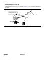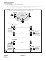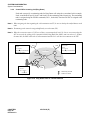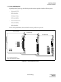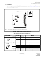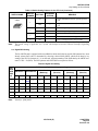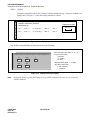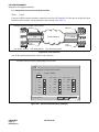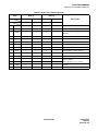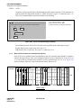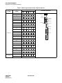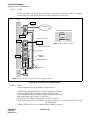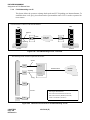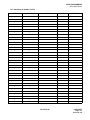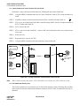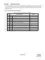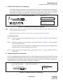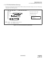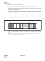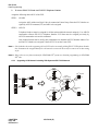
1
ND-70185 (E)
ISSUE 3
STOCK # 200869
®
Fusion Network System Manual
MAY, 2000
NEC America, Inc.
LIABILITY DISCLAIMER
NEC America, Inc. reserves the right to change the specifications, functions, or
features, at any time, without notice.
NEC America, Inc. has prepared this document for use by its employees and
customers. The information contained herein is the property of NEC America,
Inc. and shall not be reproduced without prior written approval from NEC
America, Inc.
NEAX and Dterm are registered trademarks of NEC Corporation.
All other brand or product names are or may be trademarks or registered
trademarks of, and are used to identify products or services of, their respective
owners.
MS-DOS and Microsoft are registered trademarks of Microsoft Corporation.
Microsoft Windows 95 and Windows NT are trademarks of Microsoft
Corporation.
Copyright 1998, 1999, 2000
NEC America, Inc.
Printed in the U.S.A
Issue No.
PAGE No.
4
5
Issue No.
PAGE No.
6
7
8
1
2
3
1
2
3
1
2
3
i
1
2
3
29
ii
1
2
3
30
1
2
3
iii
1
2
3
31
1
2
3
iv
1
2
3
32
1
2
3
v
1
2
3
33
1
2
3
vi
1
2
3
34
1
2
3
vii
1
2
3
35
1
2
3
viii
1
2
3
36
1
2
3
ix
1
2
3
37
1
2
3
x
1
2
3
38
1
2
3
1
1
2
3
39
1
2
3
2
1
2
3
40
1
2
3
3
1
2
3
41
1
2
3
4
1
2
3
42
1
2
3
5
1
2
3
43
1
2
3
6
1
2
3
44
1
2
3
7
1
2
3
45
1
2
3
8
1
2
3
46
1
2
3
9
1
2
3
47
1
2
3
10
1
2
3
48
1
2
3
11
1
2
3
49
1
2
3
12
1
2
3
50
1
2
3
13
1
2
3
51
1
2
3
14
1
2
3
52
1
2
3
15
1
2
3
53
1
2
3
16
1
2
3
54
1
2
3
17
1
2
3
55
1
2
3
18
1
2
3
56
1
2
3
19
1
2
3
57
1
2
3
20
1
2
3
58
1
2
3
21
1
2
3
59
1
2
3
22
1
2
3
60
1
2
3
23
1
2
3
61
1
2
3
24
1
2
3
62
1
2
3
25
1
2
3
63
1
2
3
26
1
2
3
64
1
2
3
27
1
2
3
65
1
2
3
28
1
2
3
66
1
2
3
ISSUE 1
DATE
JANUARY, 1998
ISSUE 2
DATE
ISSUE 5
DATE
MARCH, 1999
DATE
5
ISSUE 3
DATE
ISSUE 6
NEAX2400 IMX
Fusion Network System Manual
4
MAY, 2000
7
8
ISSUE 4
DATE
ISSUE 7
DATE
6
ISSUE 8
DATE
Issue Revision Sheet 1/3
ND-70185 (E) ISSUE 3
Issue No.
PAGE No.
Issue No.
PAGE No.
1
2
3
1
2
3
1
2
3
1
2
3
1
2
3
1
2
3
1
2
3
1
2
3
1
2
3
1
2
3
1
2
3
1
2
3
1
2
3
1
2
3
1
2
3
1
2
3
1
2
3
1
2
3
1
2
3
1
2
3
1
2
3
1
2
3
1
2
3
1
2
3
1
2
3
1
2
3
1
2
3
1
2
3
1
2
3
1
2
3
1
2
3
1
2
3
1
2
3
1
2
3
1
2
3
1
2
3
1
2
3
1
2
3
2
3
1
2
3
1
2
3
68
1
2
3
106
69
1
2
3
107
70
1
2
3
108
71
1
2
3
109
72
1
2
3
110
73
1
2
3
111
74
1
2
3
112
75
1
2
3
113
76
1
2
3
114
77
1
2
3
115
78
1
2
3
116
79
1
2
3
117
80
1
2
3
118
81
1
2
3
119
82
1
2
3
120
83
1
2
3
121
84
1
2
3
122
85
1
2
3
123
86
1
2
3
124
87
1
2
3
125
88
1
2
3
126
89
1
2
3
127
90
1
2
3
128
91
1
2
3
129
92
1
2
3
130
93
1
2
3
131
94
1
2
3
132
95
1
2
3
133
96
1
2
3
134
97
1
2
3
135
98
1
2
3
136
99
1
2
3
137
100
1
2
3
138
101
1
2
3
139
102
1
2
3
140
103
1
2
3
141
104
1
2
3
142
1
67
4
JANUARY, 1998
7
8
ISSUE 2
DATE
ISSUE 5
DATE
6
105
ISSUE 1
DATE
5
MARCH, 1999
NEAX2400 IMX
Fusion Network System Manual
5
ISSUE 3
DATE
ISSUE 6
DATE
4
MAY, 2000
7
8
ISSUE 4
DATE
ISSUE 7
DATE
6
ISSUE 8
DATE
Issue Revision Sheet 2/3
ND-70185 (E) ISSUE 3
Issue No.
PAGE No.
1
2
3
1
2
3
144
1
2
145
1
2
146
1
143
4
5
Issue No.
PAGE No.
6
7
1
8
2
3
181
3
3
182
3
3
183
3
2
3
184
3
147
2
3
185
3
148
2
3
186
3
149
2
3
187
3
150
2
3
188
3
151
2
3
189
3
152
2
3
190
3
153
2
3
191
3
154
2
3
192
3
155
2
3
193
3
156
2
3
194
3
157
2
3
195
3
158
2
3
196
3
159
2
3
197
3
160
2
3
198
3
161
3
162
3
163
3
164
3
165
3
166
3
167
3
168
3
169
3
170
3
171
3
172
3
173
3
174
3
175
3
176
3
177
3
178
3
179
3
180
3
ISSUE 1
DATE
JANUARY, 1998
ISSUE 2
DATE
ISSUE 5
DATE
MARCH, 1999
NEAX2400 IMX
Fusion Network System Manual
5
ISSUE 3
DATE
ISSUE 6
DATE
4
MAY, 2000
7
8
ISSUE 4
DATE
ISSUE 7
DATE
6
ISSUE 8
DATE
Issue Revision Sheet 3/3
ND-70185 (E) ISSUE 3
ND-70185 (E)
ISSUE 3
MAY, 2000
NEAX2400 IMX
Fusion Network System Manual
TABLE OF CONTENTS
Page
CHAPTER 1 INTRODUCTION . . . . . . . . . . . . . . . . . . . . . . . . . . . . . . . . . . . . . . . . . . . . . . . . . . . . . . . . . . .
1. General . . . . . . . . . . . . . . . . . . . . . . . . . . . . . . . . . . . . . . . . . . . . . . . . . . . . . . . . . . . . . . . . . . . . . . . . .
2. How to Follow This Manual . . . . . . . . . . . . . . . . . . . . . . . . . . . . . . . . . . . . . . . . . . . . . . . . . . . . . . . . . .
3. Related Manuals . . . . . . . . . . . . . . . . . . . . . . . . . . . . . . . . . . . . . . . . . . . . . . . . . . . . . . . . . . . . . . . . . .
1
1
1
2
CHAPTER 2 GENERAL . . . . . . . . . . . . . . . . . . . . . . . . . . . . . . . . . . . . . . . . . . . . . . . . . . . . . . . . . . . . . . . .
1. What is Fusion and its Advantages. . . . . . . . . . . . . . . . . . . . . . . . . . . . . . . . . . . . . . . . . . . . . . . . . . . .
1.1
Improved Inter-Office Service Features . . . . . . . . . . . . . . . . . . . . . . . . . . . . . . . . . . . . . . . . . .
1.2
Use of Telephone Numbers . . . . . . . . . . . . . . . . . . . . . . . . . . . . . . . . . . . . . . . . . . . . . . . . . . .
2. Free Numbering . . . . . . . . . . . . . . . . . . . . . . . . . . . . . . . . . . . . . . . . . . . . . . . . . . . . . . . . . . . . . . . . . .
2.1
Centralized Maintenance Administration Terminal (MAT) . . . . . . . . . . . . . . . . . . . . . . . . . . . .
3. Fusion System Configuration . . . . . . . . . . . . . . . . . . . . . . . . . . . . . . . . . . . . . . . . . . . . . . . . . . . . . . . .
4. Node . . . . . . . . . . . . . . . . . . . . . . . . . . . . . . . . . . . . . . . . . . . . . . . . . . . . . . . . . . . . . . . . . . . . . . . . . . .
5. Data Memory Configuration . . . . . . . . . . . . . . . . . . . . . . . . . . . . . . . . . . . . . . . . . . . . . . . . . . . . . . . . .
6. Fusion Network Examples . . . . . . . . . . . . . . . . . . . . . . . . . . . . . . . . . . . . . . . . . . . . . . . . . . . . . . . . . .
7. Tandem Connections via Fusion Link . . . . . . . . . . . . . . . . . . . . . . . . . . . . . . . . . . . . . . . . . . . . . . . . . .
3
3
3
3
4
4
5
6
7
8
10
CHAPTER 3 SYSTEM CONFIGURATION . . . . . . . . . . . . . . . . . . . . . . . . . . . . . . . . . . . . . . . . . . . . . . . . . .
1. Fusion System without FCH . . . . . . . . . . . . . . . . . . . . . . . . . . . . . . . . . . . . . . . . . . . . . . . . . . . . . . . . .
2. Fusion System with FCH . . . . . . . . . . . . . . . . . . . . . . . . . . . . . . . . . . . . . . . . . . . . . . . . . . . . . . . . . . .
2.1
System Configuration. . . . . . . . . . . . . . . . . . . . . . . . . . . . . . . . . . . . . . . . . . . . . . . . . . . . . . . .
2.2
Redundancy of Fusion Link . . . . . . . . . . . . . . . . . . . . . . . . . . . . . . . . . . . . . . . . . . . . . . . . . . .
3. System Considerations . . . . . . . . . . . . . . . . . . . . . . . . . . . . . . . . . . . . . . . . . . . . . . . . . . . . . . . . . . . . .
3.1
Fusion Network Conditions . . . . . . . . . . . . . . . . . . . . . . . . . . . . . . . . . . . . . . . . . . . . . . . . . . .
3.2
Centralized Billing - Fusion (Polling Method) . . . . . . . . . . . . . . . . . . . . . . . . . . . . . . . . . . . . . .
3.3
Centralized Management Report-Fusion . . . . . . . . . . . . . . . . . . . . . . . . . . . . . . . . . . . . . . . . .
3.4
Fusion Attendant/Desk Console . . . . . . . . . . . . . . . . . . . . . . . . . . . . . . . . . . . . . . . . . . . . . . .
3.4.1 Operator Call. . . . . . . . . . . . . . . . . . . . . . . . . . . . . . . . . . . . . . . . . . . . . . . . . . . . . . . .
3.4.2 Central Office Incoming Call (Ring Down) . . . . . . . . . . . . . . . . . . . . . . . . . . . . . . . . .
3.4.3 Day/Night Change. . . . . . . . . . . . . . . . . . . . . . . . . . . . . . . . . . . . . . . . . . . . . . . . . . . .
11
11
12
12
12
14
14
18
21
25
25
26
27
CHAPTER 4 INSTALLATION . . . . . . . . . . . . . . . . . . . . . . . . . . . . . . . . . . . . . . . . . . . . . . . . . . . . . . . . . . . .
1. Anti-Static Caution . . . . . . . . . . . . . . . . . . . . . . . . . . . . . . . . . . . . . . . . . . . . . . . . . . . . . . . . . . . . . . . .
1.1
Circuit Cards Required. . . . . . . . . . . . . . . . . . . . . . . . . . . . . . . . . . . . . . . . . . . . . . . . . . . . . . .
2. Key Setting on Circuit Cards . . . . . . . . . . . . . . . . . . . . . . . . . . . . . . . . . . . . . . . . . . . . . . . . . . . . . . . . .
2.1
PA-M96 (HUB) . . . . . . . . . . . . . . . . . . . . . . . . . . . . . . . . . . . . . . . . . . . . . . . . . . . . . . . . . . . . .
2.2
PA-FCHA (FCH) . . . . . . . . . . . . . . . . . . . . . . . . . . . . . . . . . . . . . . . . . . . . . . . . . . . . . . . . . . . .
2.3
PA-24DTR (DTI) . . . . . . . . . . . . . . . . . . . . . . . . . . . . . . . . . . . . . . . . . . . . . . . . . . . . . . . . . . . .
2.4
Digital PAD Setting. . . . . . . . . . . . . . . . . . . . . . . . . . . . . . . . . . . . . . . . . . . . . . . . . . . . . . . . . .
29
29
31
32
32
33
35
39
ND-70185 (E)
TABLE OF CONTENTS
Page i
Revision 3.0
TABLE OF CONTENTS (CONTINUED)
Page
3. Mounting Circuit Cards in PIM . . . . . . . . . . . . . . . . . . . . . . . . . . . . . . . . . . . . . . . . . . . . . . . . . . . . . . . 40
3.1
Mounting HUB (PA-M96) in a PIM. . . . . . . . . . . . . . . . . . . . . . . . . . . . . . . . . . . . . . . . . . . . . .
40
3.2
Mounting FCH (PA-FCHA) and DTI (PA-24DTR) Cards . . . . . . . . . . . . . . . . . . . . . . . . . . . . . 41
4. Connecting Cables. . . . . . . . . . . . . . . . . . . . . . . . . . . . . . . . . . . . . . . . . . . . . . . . . . . . . . . . . . . . . . . . 42
4.1
Connecting DTI-FCH Front Cables . . . . . . . . . . . . . . . . . . . . . . . . . . . . . . . . . . . . . . . . . . . . . 42
4.2
Connecting 10 BASE-T Cables. . . . . . . . . . . . . . . . . . . . . . . . . . . . . . . . . . . . . . . . . . . . . . . . 44
4.3
10 BASE-T Connection Procedure . . . . . . . . . . . . . . . . . . . . . . . . . . . . . . . . . . . . . . . . . . . . . 45
4.3.1 Procedure for 1-IMG System . . . . . . . . . . . . . . . . . . . . . . . . . . . . . . . . . . . . . . . . . . . 45
4.3.2 When using cable unit SR1201 ETIF CAU-n . . . . . . . . . . . . . . . . . . . . . . . . . . . . . . . 45
4.3.3 When not using the cable unit SR1201 ETIF CAU-n . . . . . . . . . . . . . . . . . . . . . . . . . 46
4.3.4 Procedure for 4-IMG System . . . . . . . . . . . . . . . . . . . . . . . . . . . . . . . . . . . . . . . . . . . 46
4.3.5 Procedure for IMX-U System . . . . . . . . . . . . . . . . . . . . . . . . . . . . . . . . . . . . . . . . . . . 47
CHAPTER 5 DATA PROGRAMMING . . . . . . . . . . . . . . . . . . . . . . . . . . . . . . . . . . . . . . . . . . . . . . . . . . . . . . 57
1. Network Data Programming Summary . . . . . . . . . . . . . . . . . . . . . . . . . . . . . . . . . . . . . . . . . . . . . . . . 58
1.1
Brand-new Fusion Network . . . . . . . . . . . . . . . . . . . . . . . . . . . . . . . . . . . . . . . . . . . . . . . . . . . 58
1.1.1 System Data. . . . . . . . . . . . . . . . . . . . . . . . . . . . . . . . . . . . . . . . . . . . . . . . . . . . . . . . 58
1.1.2 Numbering Plan Data. . . . . . . . . . . . . . . . . . . . . . . . . . . . . . . . . . . . . . . . . . . . . . . . .
58
1.1.3 Station Numbering . . . . . . . . . . . . . . . . . . . . . . . . . . . . . . . . . . . . . . . . . . . . . . . . . . . 58
1.1.4 Fusion Link Data . . . . . . . . . . . . . . . . . . . . . . . . . . . . . . . . . . . . . . . . . . . . . . . . . . . . 58
1.2
Upgrading a CCIS Network . . . . . . . . . . . . . . . . . . . . . . . . . . . . . . . . . . . . . . . . . . . . . . . . . . . 59
1.2.1 System Data. . . . . . . . . . . . . . . . . . . . . . . . . . . . . . . . . . . . . . . . . . . . . . . . . . . . . . . . 59
1.2.2 Numbering Plan Data. . . . . . . . . . . . . . . . . . . . . . . . . . . . . . . . . . . . . . . . . . . . . . . . .
59
1.2.3 Station Numbering . . . . . . . . . . . . . . . . . . . . . . . . . . . . . . . . . . . . . . . . . . . . . . . . . . . 59
1.2.4 Fusion Link Data . . . . . . . . . . . . . . . . . . . . . . . . . . . . . . . . . . . . . . . . . . . . . . . . . . . . 59
1.3
Fusion Link Data . . . . . . . . . . . . . . . . . . . . . . . . . . . . . . . . . . . . . . . . . . . . . . . . . . . . . . . . . . .
60
2. Assignment of System Data. . . . . . . . . . . . . . . . . . . . . . . . . . . . . . . . . . . . . . . . . . . . . . . . . . . . . . . . . 62
3. Assignment of FPC and MG and UNIT into Network . . . . . . . . . . . . . . . . . . . . . . . . . . . . . . . . . . . . . . 65
3.1
AFMU . . . . . . . . . . . . . . . . . . . . . . . . . . . . . . . . . . . . . . . . . . . . . . . . . . . . . . . . . . . . . . . . . . . 65
4. Assignment of Logical RT in Network DM (NDM) . . . . . . . . . . . . . . . . . . . . . . . . . . . . . . . . . . . . . . . . 66
4.1
ALRTN/ARTKN . . . . . . . . . . . . . . . . . . . . . . . . . . . . . . . . . . . . . . . . . . . . . . . . . . . . . . . . . . . . 66
5. Assignment of Numbering Data for Telephone Numbers . . . . . . . . . . . . . . . . . . . . . . . . . . . . . . . . . . . 67
6. Assignment of Telephone Numbers . . . . . . . . . . . . . . . . . . . . . . . . . . . . . . . . . . . . . . . . . . . . . . . . . . . 70
6.1
Assignment of Connection Route/Trunk Data . . . . . . . . . . . . . . . . . . . . . . . . . . . . . . . . . . . . . 72
6.1.1 When FCH is mounted in a Extended Density Slot . . . . . . . . . . . . . . . . . . . . . . . . . . 76
6.1.2 When FCH is Mounted in a High Density Slot . . . . . . . . . . . . . . . . . . . . . . . . . . . . . . 78
7. Assignment of FCH Related Data . . . . . . . . . . . . . . . . . . . . . . . . . . . . . . . . . . . . . . . . . . . . . . . . . . . . 81
7.1
Assignment of Access Code for Tandem Connection via FCCS - ACIS . . . . . . . . . . . . . . . . . 87
7.1.1 OGC . . . . . . . . . . . . . . . . . . . . . . . . . . . . . . . . . . . . . . . . . . . . . . . . . . . . . . . . . . . . . .
87
7.1.2 OGCA. . . . . . . . . . . . . . . . . . . . . . . . . . . . . . . . . . . . . . . . . . . . . . . . . . . . . . . . . . . . . 89
7.1.3 LCR/LCRS . . . . . . . . . . . . . . . . . . . . . . . . . . . . . . . . . . . . . . . . . . . . . . . . . . . . . . . . . 90
7.2
Data Assignment for 52M-SDH Interface . . . . . . . . . . . . . . . . . . . . . . . . . . . . . . . . . . . . . . . . 93
7.2.1 Data Programming . . . . . . . . . . . . . . . . . . . . . . . . . . . . . . . . . . . . . . . . . . . . . . . . . . . 94
7.3
FCCS Link via Internet/Intranet. . . . . . . . . . . . . . . . . . . . . . . . . . . . . . . . . . . . . . . . . . . . . . . . 97
7.3.1 External Router . . . . . . . . . . . . . . . . . . . . . . . . . . . . . . . . . . . . . . . . . . . . . . . . . . . . . 97
7.3.2 FCCS Networking over IP . . . . . . . . . . . . . . . . . . . . . . . . . . . . . . . . . . . . . . . . . . . . . 104
7.4
Flexible Routing - FCCS . . . . . . . . . . . . . . . . . . . . . . . . . . . . . . . . . . . . . . . . . . . . . . . . . . . . . 111
TABLE OF CONTENTS
Page ii
Revision 3.0
ND-70185 (E)
TABLE OF CONTENTS (CONTINUED)
Page
8. Office Data Sheets . . . . . . . . . . . . . . . . . . . . . . . . . . . . . . . . . . . . . . . . . . . . . . . . . . . . . . . . . . . . . . . . 112
8.1
Data Sheet for AFMUPL . . . . . . . . . . . . . . . . . . . . . . . . . . . . . . . . . . . . . . . . . . . . . . . . . . . . . 112
8.2
Data Sheet for ALRTN . . . . . . . . . . . . . . . . . . . . . . . . . . . . . . . . . . . . . . . . . . . . . . . . . . . . . . 113
8.3
Data Sheet for ANPD/ANPDL/ANDPN . . . . . . . . . . . . . . . . . . . . . . . . . . . . . . . . . . . . . . . . . . 114
8.4
Data Sheet for ASPA/ASPAL . . . . . . . . . . . . . . . . . . . . . . . . . . . . . . . . . . . . . . . . . . . . . . . . . . 115
8.5
Data Sheet for ALGNL . . . . . . . . . . . . . . . . . . . . . . . . . . . . . . . . . . . . . . . . . . . . . . . . . . . . . . 116
8.6
Data Sheet for ALGSL (TYPE1) . . . . . . . . . . . . . . . . . . . . . . . . . . . . . . . . . . . . . . . . . . . . . . . 117
8.7
Data Sheet for ALGSL (TYPE2) . . . . . . . . . . . . . . . . . . . . . . . . . . . . . . . . . . . . . . . . . . . . . . . 118
8.8
Data Sheet for ASDT. . . . . . . . . . . . . . . . . . . . . . . . . . . . . . . . . . . . . . . . . . . . . . . . . . . . . . . . 119
8.9
Data Sheet for ACRD . . . . . . . . . . . . . . . . . . . . . . . . . . . . . . . . . . . . . . . . . . . . . . . . . . . . . . . 120
8.10
Data Sheet for ACTK. . . . . . . . . . . . . . . . . . . . . . . . . . . . . . . . . . . . . . . . . . . . . . . . . . . . . . . . 122
8.11
Data Sheet for AFCH . . . . . . . . . . . . . . . . . . . . . . . . . . . . . . . . . . . . . . . . . . . . . . . . . . . . . . . 123
8.12
Data Sheet for AFPC. . . . . . . . . . . . . . . . . . . . . . . . . . . . . . . . . . . . . . . . . . . . . . . . . . . . . . . . 125
8.13
Data Sheet for ACAN . . . . . . . . . . . . . . . . . . . . . . . . . . . . . . . . . . . . . . . . . . . . . . . . . . . . . . . 127
8.14
Data Sheet for AFRT . . . . . . . . . . . . . . . . . . . . . . . . . . . . . . . . . . . . . . . . . . . . . . . . . . . . . . . . 128
8.15
Data Sheet for AETH. . . . . . . . . . . . . . . . . . . . . . . . . . . . . . . . . . . . . . . . . . . . . . . . . . . . . . . . 129
8.16
Data Sheet for AGIP . . . . . . . . . . . . . . . . . . . . . . . . . . . . . . . . . . . . . . . . . . . . . . . . . . . . . . . . 130
8.17
Data Sheet for AFIP . . . . . . . . . . . . . . . . . . . . . . . . . . . . . . . . . . . . . . . . . . . . . . . . . . . . . . . . 131
8.18
Data Sheet for AFRFL. . . . . . . . . . . . . . . . . . . . . . . . . . . . . . . . . . . . . . . . . . . . . . . . . . . . . . . 132
CHAPTER 6 POST INSTALLATION TEST . . . . . . . . . . . . . . . . . . . . . . . . . . . . . . . . . . . . . . . . . . . . . . . . .
1. How to Check Fusion Link by LEDs on FCH Card . . . . . . . . . . . . . . . . . . . . . . . . . . . . . . . . . . . . . . . .
1.1
How to check LYR LED . . . . . . . . . . . . . . . . . . . . . . . . . . . . . . . . . . . . . . . . . . . . . . . . . . . . . .
2. Repair Procedure When LED Indicates Abnormality . . . . . . . . . . . . . . . . . . . . . . . . . . . . . . . . . . . . . .
2.1
Front Cable . . . . . . . . . . . . . . . . . . . . . . . . . . . . . . . . . . . . . . . . . . . . . . . . . . . . . . . . . . . . . . .
2.2
How to Perform the Fusion Link Test. . . . . . . . . . . . . . . . . . . . . . . . . . . . . . . . . . . . . . . . . . . .
2.2.1 Fusion Link Test Mode Setting. . . . . . . . . . . . . . . . . . . . . . . . . . . . . . . . . . . . . . . . . .
2.2.2 Loopback Point Designation . . . . . . . . . . . . . . . . . . . . . . . . . . . . . . . . . . . . . . . . . . .
2.3
Test Procedure . . . . . . . . . . . . . . . . . . . . . . . . . . . . . . . . . . . . . . . . . . . . . . . . . . . . . . . . . . . .
3. FCCS Network Connection Test . . . . . . . . . . . . . . . . . . . . . . . . . . . . . . . . . . . . . . . . . . . . . . . . . . . . .
3.1
Station-to-Station Connection Test (via FCCS) . . . . . . . . . . . . . . . . . . . . . . . . . . . . . . . . . . . .
3.1.1 FCCS Call Origination Test . . . . . . . . . . . . . . . . . . . . . . . . . . . . . . . . . . . . . . . . . . . .
3.1.2 FCCS Call Termination Test . . . . . . . . . . . . . . . . . . . . . . . . . . . . . . . . . . . . . . . . . . .
3.2
ATTCON ConnectionTest (via FCCS) . . . . . . . . . . . . . . . . . . . . . . . . . . . . . . . . . . . . . . . . . .
3.2.1 ATTCON Call Origination Test. . . . . . . . . . . . . . . . . . . . . . . . . . . . . . . . . . . . . . . . . .
3.2.2 ATTCON Call Termination Test . . . . . . . . . . . . . . . . . . . . . . . . . . . . . . . . . . . . . . . . .
3.3
Line (LC, ELC, DLC Card) Connection Test (via FCCS). . . . . . . . . . . . . . . . . . . . . . . . . . . . .
3.3.1 Line Origination Test: Confirmation of Physical/Telephone STN Number . . . . . . . . .
3.3.2 Line Termination Test: Confirmation of Telephone STN Number . . . . . . . . . . . . . . .
3.3.3 Line Connection Test: Case of Hot Line/House Phone Involved . . . . . . . . . . . . . . . .
3.4
3-party Conference Trunk Function Test (via FCCS). . . . . . . . . . . . . . . . . . . . . . . . . . . . . . . .
3.5
FCCS Alternate RoutingTest . . . . . . . . . . . . . . . . . . . . . . . . . . . . . . . . . . . . . . . . . . . . . . . . .
3.5.1 Primary Route Trunk Test . . . . . . . . . . . . . . . . . . . . . . . . . . . . . . . . . . . . . . . . . . . . .
3.5.2 Alternate Route Trunk Test . . . . . . . . . . . . . . . . . . . . . . . . . . . . . . . . . . . . . . . . . . . .
4. Fusion and Non-Fusion Connection Tests . . . . . . . . . . . . . . . . . . . . . . . . . . . . . . . . . . . . . . . . . . . . . .
4.1
When Seizing a Trunk from a Station . . . . . . . . . . . . . . . . . . . . . . . . . . . . . . . . . . . . . . . . . . .
4.2
When Seizing a Trunk from an ATTCON. . . . . . . . . . . . . . . . . . . . . . . . . . . . . . . . . . . . . . . . .
5. SDT Card Loopback Test . . . . . . . . . . . . . . . . . . . . . . . . . . . . . . . . . . . . . . . . . . . . . . . . . . . . . . . . . . .
ND-70185 (E)
133
133
134
134
134
135
135
135
137
138
138
138
139
140
140
140
141
141
141
141
142
142
143
143
143
144
144
145
TABLE OF CONTENTS
Page iii
Revision 3.0
TABLE OF CONTENTS (CONTINUED)
Page
CHAPTER 7 TROUBLESHOOTING . . . . . . . . . . . . . . . . . . . . . . . . . . . . . . . . . . . . . . . . . . . . . . . . . . . . . . 147
1. List of Fusion-related System Messages . . . . . . . . . . . . . . . . . . . . . . . . . . . . . . . . . . . . . . . . . . . . . . . 147
2. 3-B PM C-level Infinite Loop (Permanent) . . . . . . . . . . . . . . . . . . . . . . . . . . . . . . . . . . . . . . . . . . . . . . 149
2.1
Repair Procedure . . . . . . . . . . . . . . . . . . . . . . . . . . . . . . . . . . . . . . . . . . . . . . . . . . . . . . . . . . 149
3. 3-C PM C-level Infinite Loop (Temporary) . . . . . . . . . . . . . . . . . . . . . . . . . . . . . . . . . . . . . . . . . . . . . . 151
3.1
Repair Procedure . . . . . . . . . . . . . . . . . . . . . . . . . . . . . . . . . . . . . . . . . . . . . . . . . . . . . . . . . . 151
4. 3-D PM Lockup Failure (Permanent) . . . . . . . . . . . . . . . . . . . . . . . . . . . . . . . . . . . . . . . . . . . . . . . . . . 151
4.1
Repair Procedure . . . . . . . . . . . . . . . . . . . . . . . . . . . . . . . . . . . . . . . . . . . . . . . . . . . . . . . . . . 152
5. 3-E PM Lockup Failure (Temporary) . . . . . . . . . . . . . . . . . . . . . . . . . . . . . . . . . . . . . . . . . . . . . . . . . . 152
5.1
Repair Procedure . . . . . . . . . . . . . . . . . . . . . . . . . . . . . . . . . . . . . . . . . . . . . . . . . . . . . . . . . . 152
6. 13-H/I/J Signaling Link Failure (Permanent)/(Temporary)/(Recovery) . . . . . . . . . . . . . . . . . . . . . . . . . 153
6.1
Repair Procedure . . . . . . . . . . . . . . . . . . . . . . . . . . . . . . . . . . . . . . . . . . . . . . . . . . . . . . . . . . 154
6.2
Repair Procedure . . . . . . . . . . . . . . . . . . . . . . . . . . . . . . . . . . . . . . . . . . . . . . . . . . . . . . . . . . 155
7. 23-S FCH Failure Notification (Detection) . . . . . . . . . . . . . . . . . . . . . . . . . . . . . . . . . . . . . . . . . . . . . . 155
7.1
Repair Procedure . . . . . . . . . . . . . . . . . . . . . . . . . . . . . . . . . . . . . . . . . . . . . . . . . . . . . . . . . . 156
8. 23-T FCH Fault Notification (Recovery) . . . . . . . . . . . . . . . . . . . . . . . . . . . . . . . . . . . . . . . . . . . . . . . . 159
9. 23-U FCH Status Information. . . . . . . . . . . . . . . . . . . . . . . . . . . . . . . . . . . . . . . . . . . . . . . . . . . . . . . . 160
9.1
FLTINF = 00H Initial Setting Failure . . . . . . . . . . . . . . . . . . . . . . . . . . . . . . . . . . . . . . . . . . . . 161
9.2
FLTINF = 18H Spanning Tree Abnormal Answer . . . . . . . . . . . . . . . . . . . . . . . . . . . . . . . . . . 162
9.2.1 Repair Procedure . . . . . . . . . . . . . . . . . . . . . . . . . . . . . . . . . . . . . . . . . . . . . . . . . . . . 163
9.3
FLTINF = 1DH ETHER Transfer Failure . . . . . . . . . . . . . . . . . . . . . . . . . . . . . . . . . . . . . . . . . 164
9.4
FLTINF = 1EH Spanning Tree Generation End . . . . . . . . . . . . . . . . . . . . . . . . . . . . . . . . . . . . 165
9.5
FLTINF = 1FH Spanning Tree Generation Start . . . . . . . . . . . . . . . . . . . . . . . . . . . . . . . . . . . 166
9.6
FLTINF = 85H Checksum Verification Failure . . . . . . . . . . . . . . . . . . . . . . . . . . . . . . . . . . . . . 166
10. 23-W FCH Alternate Routing Start Notification . . . . . . . . . . . . . . . . . . . . . . . . . . . . . . . . . . . . . . . . . . 167
11. 23-X FCH Alternate Routing End Notification . . . . . . . . . . . . . . . . . . . . . . . . . . . . . . . . . . . . . . . . . . . 167
CHAPTER 8 EX- FCCS . . . . . . . . . . . . . . . . . . . . . . . . . . . . . . . . . . . . . . . . . . . . . . . . . . . . . . . . . . . . . . . .
1. General . . . . . . . . . . . . . . . . . . . . . . . . . . . . . . . . . . . . . . . . . . . . . . . . . . . . . . . . . . . . . . . . . . . . . . . .
2. EX-FCCS Network Configuration. . . . . . . . . . . . . . . . . . . . . . . . . . . . . . . . . . . . . . . . . . . . . . . . . . . . .
2.1
Network Configuration. . . . . . . . . . . . . . . . . . . . . . . . . . . . . . . . . . . . . . . . . . . . . . . . . . . . . . .
2.2
Conditions for Network Establishment (NEAX2000 IVS2 to NEAX2400 IMX Connection) . . .
2.3
Conditions for Network Establishment (NEAX2400 IMX to NEAX2400 IMX Connection) . . .
2.4
Fusion Network Group (FUG) . . . . . . . . . . . . . . . . . . . . . . . . . . . . . . . . . . . . . . . . . . . . . . . . .
2.5
Interactions . . . . . . . . . . . . . . . . . . . . . . . . . . . . . . . . . . . . . . . . . . . . . . . . . . . . . . . . . . . . . . .
3. EX-FCCS Features . . . . . . . . . . . . . . . . . . . . . . . . . . . . . . . . . . . . . . . . . . . . . . . . . . . . . . . . . . . . . . .
3.1
Number Portability. . . . . . . . . . . . . . . . . . . . . . . . . . . . . . . . . . . . . . . . . . . . . . . . . . . . . . . . . .
3.2
Centralized-MAT for EX-FCCS . . . . . . . . . . . . . . . . . . . . . . . . . . . . . . . . . . . . . . . . . . . . . . . .
3.3
CCIS Features Activated with EX-FCCS. . . . . . . . . . . . . . . . . . . . . . . . . . . . . . . . . . . . . . . . .
3.4
Centralized Message Center Interface - EX-FCCS. . . . . . . . . . . . . . . . . . . . . . . . . . . . . . . . .
3.5
Centralized Billing - EX-FCCS (Polling Method) . . . . . . . . . . . . . . . . . . . . . . . . . . . . . . . . . . .
4. Data Programming . . . . . . . . . . . . . . . . . . . . . . . . . . . . . . . . . . . . . . . . . . . . . . . . . . . . . . . . . . . . . . . .
4.1
Brand-new EX-FCCS Network . . . . . . . . . . . . . . . . . . . . . . . . . . . . . . . . . . . . . . . . . . . . . . . .
4.1.1 To Log in to All Nodes in EX-FCCS Network . . . . . . . . . . . . . . . . . . . . . . . . . . . . . . .
4.1.2 To Access EX-FCCS Trunk via ACC + Telephone Number . . . . . . . . . . . . . . . . . . .
4.1.3 To Access EX-FCCS Trunk via EX-FCCS Telephone Number . . . . . . . . . . . . . . . . .
4.2
Upgrading CCIS Network to EX-FCCS Network. . . . . . . . . . . . . . . . . . . . . . . . . . . . . . . . . . .
4.2.1 Upgrading CCIS between FUGs to EX-FCCS Network . . . . . . . . . . . . . . . . . . . . . . .
4.2.2 Upgrading CCIS between FUG and IVS2 System to Enhanced CCIS Network . . . .
4.2.3 Upgrading CCIS Network including IVS2 System to EX-FCCS Network . . . . . . . . . .
TABLE OF CONTENTS
Page iv
Revision 3.0
ND-70185 (E)
169
169
170
170
171
172
173
174
175
175
177
180
182
184
185
186
186
191
192
193
193
195
196
LIST OF FIGURES
Figure
Title
Page
Figure 2-1
Figure 2-2
Figure 2-3
Figure 2-4
Figure 2-5
Figure 2-6
Figure 2-7
Figure 2-8
Figure 2-9
Figure 2-10
Figure 2-11
Figure 3-1
Figure 3-2
Figure 3-3
Figure 3-4
Figure 3-5
Figure 3-6
Figure 3-7
Figure 3-8
Figure 3-9
Figure 3-10
Figure 3-11
Figure 3-12
Figure 3-13
Figure 3-14
Figure 3-15
Figure 3-16
Figure 3-17
Figure 3-18
Figure 3-19
Figure 3-20
Figure 4-1
Figure 4-2
Figure 4-3
Figure 4-4
Figure 4-5
Figure 4-6
Figure 4-7
Figure 4-8
Figure 4-9
Figure 4-10
Figure 4-11
Figure 4-12
Figure 4-13
Figure 4-14
Figure 4-15
Figure 4-16
Figure 5-1
Telephone Number . . . . . . . . . . . . . . . . . . . . . . . . . . . . . . . . . . . . . . . . . . . . . . . . . . . . . . . . .
Free Location . . . . . . . . . . . . . . . . . . . . . . . . . . . . . . . . . . . . . . . . . . . . . . . . . . . . . . . . . . . . . .
Centralized MAT on Fusion Network . . . . . . . . . . . . . . . . . . . . . . . . . . . . . . . . . . . . . . . . . . . .
Fusion System Configuration (with FCH). . . . . . . . . . . . . . . . . . . . . . . . . . . . . . . . . . . . . . . . .
Fusion System Configuration (without FCH) . . . . . . . . . . . . . . . . . . . . . . . . . . . . . . . . . . . . . .
Maximum System Configuration . . . . . . . . . . . . . . . . . . . . . . . . . . . . . . . . . . . . . . . . . . . . . . .
Network Data Memory . . . . . . . . . . . . . . . . . . . . . . . . . . . . . . . . . . . . . . . . . . . . . . . . . . . . . . .
Network Data Memory Copy . . . . . . . . . . . . . . . . . . . . . . . . . . . . . . . . . . . . . . . . . . . . . . . . . .
Closed Numbering Fusion-CCIS Network . . . . . . . . . . . . . . . . . . . . . . . . . . . . . . . . . . . . . . . .
Open Numbering Fusion-CCIS Network . . . . . . . . . . . . . . . . . . . . . . . . . . . . . . . . . . . . . . . . .
Tandem Connections via Fusion Link . . . . . . . . . . . . . . . . . . . . . . . . . . . . . . . . . . . . . . . . . . .
Fusion System Configuration without FCH . . . . . . . . . . . . . . . . . . . . . . . . . . . . . . . . . . . . . . .
Fusion System Configuration with FCH . . . . . . . . . . . . . . . . . . . . . . . . . . . . . . . . . . . . . . . . . .
Redundant Configuration (LANI, HUB, FCH, and DTI) . . . . . . . . . . . . . . . . . . . . . . . . . . . . . .
Redundant Configuration (HUB, FCH, and DTI) . . . . . . . . . . . . . . . . . . . . . . . . . . . . . . . . . . .
Redundant Configuration (FCH and DTI). . . . . . . . . . . . . . . . . . . . . . . . . . . . . . . . . . . . . . . . .
Non-Redundant Configuration . . . . . . . . . . . . . . . . . . . . . . . . . . . . . . . . . . . . . . . . . . . . . . . . .
Fusion Network Topologies . . . . . . . . . . . . . . . . . . . . . . . . . . . . . . . . . . . . . . . . . . . . . . . . . . .
Leading Tandem Connections . . . . . . . . . . . . . . . . . . . . . . . . . . . . . . . . . . . . . . . . . . . . . . . . .
Maximum Number of Ports between Nodes . . . . . . . . . . . . . . . . . . . . . . . . . . . . . . . . . . . . . .
Connection Trunk Alternate Routing . . . . . . . . . . . . . . . . . . . . . . . . . . . . . . . . . . . . . . . . . . . .
Fusion Network on an Associated Basis . . . . . . . . . . . . . . . . . . . . . . . . . . . . . . . . . . . . . . . . .
Centralized Billing - Fusion (1/3) . . . . . . . . . . . . . . . . . . . . . . . . . . . . . . . . . . . . . . . . . . . . . . .
Centralized Management Report-Fusion . . . . . . . . . . . . . . . . . . . . . . . . . . . . . . . . . . . . . . . . .
Centralized Management Report-Fusion (Example 1). . . . . . . . . . . . . . . . . . . . . . . . . . . . . . .
Centralized Management Report-Fusion (Example 2). . . . . . . . . . . . . . . . . . . . . . . . . . . . . . .
Centralized Management Report-Fusion (Example 3). . . . . . . . . . . . . . . . . . . . . . . . . . . . . . .
Operator Calls on a Fusion Network . . . . . . . . . . . . . . . . . . . . . . . . . . . . . . . . . . . . . . . . . . . .
Ring Down Calls on a Fusion Network. . . . . . . . . . . . . . . . . . . . . . . . . . . . . . . . . . . . . . . . . . .
Day/Night Information Transfer by ATTCON/DESKCON. . . . . . . . . . . . . . . . . . . . . . . . . . . . .
Day/Night Information Transfer . . . . . . . . . . . . . . . . . . . . . . . . . . . . . . . . . . . . . . . . . . . . . . . .
Static Caution Indicator . . . . . . . . . . . . . . . . . . . . . . . . . . . . . . . . . . . . . . . . . . . . . . . . . . . . . .
How to Use the Anti-static Kit. . . . . . . . . . . . . . . . . . . . . . . . . . . . . . . . . . . . . . . . . . . . . . . . . .
Circuit Cards for Fusion . . . . . . . . . . . . . . . . . . . . . . . . . . . . . . . . . . . . . . . . . . . . . . . . . . . . . .
Switch Setting on HUB (PA-M96) Card . . . . . . . . . . . . . . . . . . . . . . . . . . . . . . . . . . . . . . . . . .
Switch Setting on FCH (PA-FCHA) Card . . . . . . . . . . . . . . . . . . . . . . . . . . . . . . . . . . . . . . . . .
Switch Locations on DTI (PA-24DTR) Card. . . . . . . . . . . . . . . . . . . . . . . . . . . . . . . . . . . . . . .
Mounting HUB Card in PIM 0. . . . . . . . . . . . . . . . . . . . . . . . . . . . . . . . . . . . . . . . . . . . . . . . . .
Mounting FCH and DTI Cards . . . . . . . . . . . . . . . . . . . . . . . . . . . . . . . . . . . . . . . . . . . . . . . . .
Connecting Front Cables . . . . . . . . . . . . . . . . . . . . . . . . . . . . . . . . . . . . . . . . . . . . . . . . . . . . .
FCH Cascade Connections . . . . . . . . . . . . . . . . . . . . . . . . . . . . . . . . . . . . . . . . . . . . . . . . . . .
Overall 10 BASE-T Connections . . . . . . . . . . . . . . . . . . . . . . . . . . . . . . . . . . . . . . . . . . . . . . .
Connecting 10 BASE-T Cables (example). . . . . . . . . . . . . . . . . . . . . . . . . . . . . . . . . . . . . . . .
Examples of Ethernet Cable Connection-FCH in PIM0 (1-IMG System) (1/2). . . . . . . . . . . . .
Examples of Ethernet Cable Connection-FCH in PIM1 (1-IMG System) . . . . . . . . . . . . . . . . .
Examples of Ethernet Cable Connection-FCH in PIM2 (1-IMG System) (1/2). . . . . . . . . . . . .
Examples of Ethernet Cable Connection-FCH in PIM3 (1-IMG System) (1/2). . . . . . . . . . . . .
Data Programming Flow Chart. . . . . . . . . . . . . . . . . . . . . . . . . . . . . . . . . . . . . . . . . . . . . . . . .
ND-70185 (E)
3
4
4
5
5
6
7
8
8
9
10
11
12
13
13
13
14
14
15
15
16
16
18
21
22
23
24
25
26
27
27
29
30
31
32
33
35
40
41
42
43
44
48
49
51
52
54
57
LIST OF FIGURES
Page v
Revision 3.0
LIST OF FIGURES (CONTINUED)
Figure
Title
Figure 5-2
Figure 5-3
Figure 5-4
Figure 5-5
Figure 5-6
Figure 5-7
Figure 5-8
Figure 5-9
Figure 5-10
Figure 5-11
Figure 5-12
Figure 5-13
Figure 5-14
Figure 5-15
Figure 5-16
Figure 5-17
Figure 5-18
Figure 5-19
Figure 5-20
Figure 5-21
Figure 5-22
Figure 5-23
Figure 5-24
Figure 5-25
Figure 5-26
Figure 5-27
Figure 5-28
Figure 5-29
Figure 5-30
Figure 5-31
Figure 5-32
Figure 5-33
Figure 5-34
Figure 5-35
Figure 5-36
Figure 5-37
Figure 5-38
Figure 5-39
Figure 5-40
Figure 5-41
Figure 5-42
Figure 5-43
Figure 5-44
Figure 5-45
Figure 5-46
Figure 5-47
Figure 5-48
Figure 5-49
Figure 5-50
Fusion-CCIS Network . . . . . . . . . . . . . . . . . . . . . . . . . . . . . . . . . . . . . . . . . . . . . . . . . . . . . . .
How to Upgrade the Numbering Plan Data of an Existing CCIS Network . . . . . . . . . . . . . . . .
Assignment of Memory Block. . . . . . . . . . . . . . . . . . . . . . . . . . . . . . . . . . . . . . . . . . . . . . . . . .
LDM and NDM Allocation (ASYDL) . . . . . . . . . . . . . . . . . . . . . . . . . . . . . . . . . . . . . . . . . . . . .
Self-FPC Assignment. . . . . . . . . . . . . . . . . . . . . . . . . . . . . . . . . . . . . . . . . . . . . . . . . . . . . . . .
ASYDN Command Display (example) . . . . . . . . . . . . . . . . . . . . . . . . . . . . . . . . . . . . . . . . . . .
Assignment of Module Accommodation Data . . . . . . . . . . . . . . . . . . . . . . . . . . . . . . . . . . . . .
AFMU Command Display. . . . . . . . . . . . . . . . . . . . . . . . . . . . . . . . . . . . . . . . . . . . . . . . . . . . .
Telephone Number Required. . . . . . . . . . . . . . . . . . . . . . . . . . . . . . . . . . . . . . . . . . . . . . . . . .
Assignment of Logical Route Number . . . . . . . . . . . . . . . . . . . . . . . . . . . . . . . . . . . . . . . . . . .
ALRTN Command Display . . . . . . . . . . . . . . . . . . . . . . . . . . . . . . . . . . . . . . . . . . . . . . . . . . . .
Telephone Number Allocation . . . . . . . . . . . . . . . . . . . . . . . . . . . . . . . . . . . . . . . . . . . . . . . . .
ANPDN Sample Data Sheet . . . . . . . . . . . . . . . . . . . . . . . . . . . . . . . . . . . . . . . . . . . . . . . . . .
ANPDN Command Display . . . . . . . . . . . . . . . . . . . . . . . . . . . . . . . . . . . . . . . . . . . . . . . . . . .
ASPAN Sample Data Sheet. . . . . . . . . . . . . . . . . . . . . . . . . . . . . . . . . . . . . . . . . . . . . . . . . . .
ASPAN Command Display. . . . . . . . . . . . . . . . . . . . . . . . . . . . . . . . . . . . . . . . . . . . . . . . . . . .
ALGSN Sample Data Sheet. . . . . . . . . . . . . . . . . . . . . . . . . . . . . . . . . . . . . . . . . . . . . . . . . . .
ALGSN Command Display (example) . . . . . . . . . . . . . . . . . . . . . . . . . . . . . . . . . . . . . . . . . . .
B-ch and D-ch . . . . . . . . . . . . . . . . . . . . . . . . . . . . . . . . . . . . . . . . . . . . . . . . . . . . . . . . . . . . .
ACRD Command Display (example) . . . . . . . . . . . . . . . . . . . . . . . . . . . . . . . . . . . . . . . . . . . .
ACTK Command Display (example) . . . . . . . . . . . . . . . . . . . . . . . . . . . . . . . . . . . . . . . . . . . .
Mounting FCH and DTI Cards in Regular Density Slots . . . . . . . . . . . . . . . . . . . . . . . . . . . . .
Mounting FCH and DTI Cards in High-Density Slots . . . . . . . . . . . . . . . . . . . . . . . . . . . . . . . .
How to Assign C_LEN Data (Type 2). . . . . . . . . . . . . . . . . . . . . . . . . . . . . . . . . . . . . . . . . . . .
MBCT Command Display. . . . . . . . . . . . . . . . . . . . . . . . . . . . . . . . . . . . . . . . . . . . . . . . . . . . .
Assignment of FCH Number . . . . . . . . . . . . . . . . . . . . . . . . . . . . . . . . . . . . . . . . . . . . . . . . . .
AFCH Command Display (example) . . . . . . . . . . . . . . . . . . . . . . . . . . . . . . . . . . . . . . . . . . . .
AFRT Sample Data Sheet . . . . . . . . . . . . . . . . . . . . . . . . . . . . . . . . . . . . . . . . . . . . . . . . . . . .
AFRT Command Display . . . . . . . . . . . . . . . . . . . . . . . . . . . . . . . . . . . . . . . . . . . . . . . . . . . . .
Fusion Network (example) . . . . . . . . . . . . . . . . . . . . . . . . . . . . . . . . . . . . . . . . . . . . . . . . . . . .
AFPC Command Display (example) . . . . . . . . . . . . . . . . . . . . . . . . . . . . . . . . . . . . . . . . . . . .
AFPC Sample Data Sheet . . . . . . . . . . . . . . . . . . . . . . . . . . . . . . . . . . . . . . . . . . . . . . . . . . . .
ACAN Sample Data Sheet . . . . . . . . . . . . . . . . . . . . . . . . . . . . . . . . . . . . . . . . . . . . . . . . . . . .
ACAN Command Display (example) . . . . . . . . . . . . . . . . . . . . . . . . . . . . . . . . . . . . . . . . . . . .
Example of OGC . . . . . . . . . . . . . . . . . . . . . . . . . . . . . . . . . . . . . . . . . . . . . . . . . . . . . . . . . . .
Example of OGCA . . . . . . . . . . . . . . . . . . . . . . . . . . . . . . . . . . . . . . . . . . . . . . . . . . . . . . . . . .
Example of LCR/LCRS . . . . . . . . . . . . . . . . . . . . . . . . . . . . . . . . . . . . . . . . . . . . . . . . . . . . . .
External Router - Overview . . . . . . . . . . . . . . . . . . . . . . . . . . . . . . . . . . . . . . . . . . . . . . . . . . .
Hardware Connections for External Router . . . . . . . . . . . . . . . . . . . . . . . . . . . . . . . . . . . . . . .
Connection Route Class Data Sample. . . . . . . . . . . . . . . . . . . . . . . . . . . . . . . . . . . . . . . . . . .
Sample Data Assignment (ACTK) . . . . . . . . . . . . . . . . . . . . . . . . . . . . . . . . . . . . . . . . . . . . . .
Assignment of FCHN (Example) . . . . . . . . . . . . . . . . . . . . . . . . . . . . . . . . . . . . . . . . . . . . . . .
Sample Data Assignment (AFPC) . . . . . . . . . . . . . . . . . . . . . . . . . . . . . . . . . . . . . . . . . . . . . .
Internal LAN Routing Data Assignment Image (Example) . . . . . . . . . . . . . . . . . . . . . . . . . . . .
Sample Data Assignment (AETH) . . . . . . . . . . . . . . . . . . . . . . . . . . . . . . . . . . . . . . . . . . . . . .
How to Assign Destination IP and Next IP . . . . . . . . . . . . . . . . . . . . . . . . . . . . . . . . . . . . . . . .
Sample Data Assignment (ACAN) . . . . . . . . . . . . . . . . . . . . . . . . . . . . . . . . . . . . . . . . . . . . . .
FCCS Networking over IP - Overview . . . . . . . . . . . . . . . . . . . . . . . . . . . . . . . . . . . . . . . . . . .
Hardware Connections for FCCS Networking over IP . . . . . . . . . . . . . . . . . . . . . . . . . . . . . . .
LIST OF FIGURES
Page vi
Revision 3.0
Page
ND-70185 (E)
60
61
62
62
63
64
65
65
66
66
67
67
68
68
69
69
70
71
72
72
76
76
78
79
81
82
82
83
83
84
84
85
86
86
87
89
90
97
97
98
99
100
101
101
102
102
103
104
104
LIST OF FIGURES (CONTINUED)
Figure
Title
Page
Figure 5-51
Figure 5-52
Figure 5-53
Figure 5-54
Figure 5-55
Figure 5-56
Figure 5-57
Figure 5-58
Figure 5-59
Figure 6-1
Figure 6-2
Figure 6-3
Figure 6-4
Figure 6-5
Figure 6-6
Figure 6-7
Figure 6-8
Figure 6-9
Figure 6-10
Figure 6-11
Figure 6-12
Figure 6-13
Figure 6-14
Figure 6-15
Figure 7-1
Figure 7-2
Figure 7-3
Figure 7-4
Figure 7-5
Figure 7-6
Figure 7-7
Figure 7-8
Figure 7-9
Figure 7-10
Figure 7-11
Figure 7-12
Figure 7-13
Figure 7-14
Figure 7-15
Figure 7-16
Figure 7-17
Figure 7-18
Figure 7-19
Figure 7-20
Figure 7-21
Figure 7-22
Figure 7-23
Figure 7-24
Figure 7-25
Sample Data Assignment (ACRD) . . . . . . . . . . . . . . . . . . . . . . . . . . . . . . . . . . . . . . . . . . . . . .
Sample Data Assignment (ACTK) . . . . . . . . . . . . . . . . . . . . . . . . . . . . . . . . . . . . . . . . . . . . . .
Assignment of FCHN (Example) . . . . . . . . . . . . . . . . . . . . . . . . . . . . . . . . . . . . . . . . . . . . . . .
Sample Data Assignment (AETH) . . . . . . . . . . . . . . . . . . . . . . . . . . . . . . . . . . . . . . . . . . . . . .
How to Assign Destination IP and Next IP . . . . . . . . . . . . . . . . . . . . . . . . . . . . . . . . . . . . . . . .
Sample Data Assignment (ACAN) . . . . . . . . . . . . . . . . . . . . . . . . . . . . . . . . . . . . . . . . . . . . . .
Sample Data Assignment (AFRT) . . . . . . . . . . . . . . . . . . . . . . . . . . . . . . . . . . . . . . . . . . . . . .
Sample Data Assignment (AGIP). . . . . . . . . . . . . . . . . . . . . . . . . . . . . . . . . . . . . . . . . . . . . . .
“Basic LENS Data” Assignment of Speech Channels (AFIP) . . . . . . . . . . . . . . . . . . . . . . . . .
Fusion Network . . . . . . . . . . . . . . . . . . . . . . . . . . . . . . . . . . . . . . . . . . . . . . . . . . . . . . . . . . . .
LED Indications on Fusion Link Related Circuit Cards . . . . . . . . . . . . . . . . . . . . . . . . . . . . . .
Fusion Link Test Mode. . . . . . . . . . . . . . . . . . . . . . . . . . . . . . . . . . . . . . . . . . . . . . . . . . . . . . .
Loopback Points of DTI Card . . . . . . . . . . . . . . . . . . . . . . . . . . . . . . . . . . . . . . . . . . . . . . . . . .
How to Set the Fusion Link Test Mode . . . . . . . . . . . . . . . . . . . . . . . . . . . . . . . . . . . . . . . . . .
Loopback Point Designation . . . . . . . . . . . . . . . . . . . . . . . . . . . . . . . . . . . . . . . . . . . . . . . . . .
Fusion Link-Test Results . . . . . . . . . . . . . . . . . . . . . . . . . . . . . . . . . . . . . . . . . . . . . . . . . . . . .
Station-to-Station Connection Test (origination) via FCCS . . . . . . . . . . . . . . . . . . . . . . . . . . .
ATTCON Connection Test (origination) via FCCS. . . . . . . . . . . . . . . . . . . . . . . . . . . . . . . . . .
Line Connection Test (origination) via FCCS. . . . . . . . . . . . . . . . . . . . . . . . . . . . . . . . . . . . . .
3-party Conference Trunk Function Test via FCCS . . . . . . . . . . . . . . . . . . . . . . . . . . . . . . . . .
Fusion Alternate Routing Test . . . . . . . . . . . . . . . . . . . . . . . . . . . . . . . . . . . . . . . . . . . . . . . . .
CCIS-FCCS Outgoing Call Test. . . . . . . . . . . . . . . . . . . . . . . . . . . . . . . . . . . . . . . . . . . . . . . .
Loopback Points of SDT Card . . . . . . . . . . . . . . . . . . . . . . . . . . . . . . . . . . . . . . . . . . . . . . . . .
Loopback Setting by P-SW key on PA-SDTA Card . . . . . . . . . . . . . . . . . . . . . . . . . . . . . . . . .
Related Hardware . . . . . . . . . . . . . . . . . . . . . . . . . . . . . . . . . . . . . . . . . . . . . . . . . . . . . . . . . .
3-B PM C-level Infinite Loop (Permanent) . . . . . . . . . . . . . . . . . . . . . . . . . . . . . . . . . . . . . . . .
How to Initialize the FCH (PA-FCHA) Card . . . . . . . . . . . . . . . . . . . . . . . . . . . . . . . . . . . . . . .
How to Replace the FCH (PA-FCHA) Card . . . . . . . . . . . . . . . . . . . . . . . . . . . . . . . . . . . . . . .
3-C PM C-level Infinite Loop (Temporary) . . . . . . . . . . . . . . . . . . . . . . . . . . . . . . . . . . . . . . . .
3-D PM Lockup Failure (Permanent) . . . . . . . . . . . . . . . . . . . . . . . . . . . . . . . . . . . . . . . . . . . .
3-E PM Lockup Failure (Temporary) . . . . . . . . . . . . . . . . . . . . . . . . . . . . . . . . . . . . . . . . . . . .
Fusion Link (Signaling Link) Failure . . . . . . . . . . . . . . . . . . . . . . . . . . . . . . . . . . . . . . . . . . . . .
13-H/13-I/13-J Signaling Link Failure System Message . . . . . . . . . . . . . . . . . . . . . . . . . . . . .
FCH-DTI Connection . . . . . . . . . . . . . . . . . . . . . . . . . . . . . . . . . . . . . . . . . . . . . . . . . . . . . . . .
23-S FCH Failure Notification . . . . . . . . . . . . . . . . . . . . . . . . . . . . . . . . . . . . . . . . . . . . . . . . .
10 BASE-T Cable Connection Check . . . . . . . . . . . . . . . . . . . . . . . . . . . . . . . . . . . . . . . . . . .
How to Check 10 BASE-T Cables . . . . . . . . . . . . . . . . . . . . . . . . . . . . . . . . . . . . . . . . . . . . . .
How to Replace HUB (PA-M96) Card . . . . . . . . . . . . . . . . . . . . . . . . . . . . . . . . . . . . . . . . . . .
23-T FCCH Fault Recovery Notification. . . . . . . . . . . . . . . . . . . . . . . . . . . . . . . . . . . . . . . . . .
23-U FCCH Status Information . . . . . . . . . . . . . . . . . . . . . . . . . . . . . . . . . . . . . . . . . . . . . . . .
23-U FCCH Status Notification - Initial Setting Failure. . . . . . . . . . . . . . . . . . . . . . . . . . . . . . .
23-U FCCH Status Notification - Spanning Tree Abnormal Answer . . . . . . . . . . . . . . . . . . . .
Spanning Tree Abnormal Answer . . . . . . . . . . . . . . . . . . . . . . . . . . . . . . . . . . . . . . . . . . . . . .
23-U ETHER Transfer Failure . . . . . . . . . . . . . . . . . . . . . . . . . . . . . . . . . . . . . . . . . . . . . . . . .
23-U FCCH Status Notification - Spanning Tree Generation End . . . . . . . . . . . . . . . . . . . . . .
23-U FCCH Status Notification - Spanning Tree Generation. . . . . . . . . . . . . . . . . . . . . . . . . .
23-U FCCH Status Notification - Checksum Verification Failure . . . . . . . . . . . . . . . . . . . . . . .
23-W FCCH Alternate Routing Start Notification . . . . . . . . . . . . . . . . . . . . . . . . . . . . . . . . . . .
23-X FCCH Alternate Routing End Notification . . . . . . . . . . . . . . . . . . . . . . . . . . . . . . . . . . . .
ND-70185 (E)
105
105
106
107
107
108
108
109
110
133
134
135
136
137
137
138
139
140
141
142
143
144
145
145
148
149
149
150
151
151
152
153
153
154
155
156
157
158
159
160
161
162
163
164
165
166
166
167
167
LIST OF FIGURES
Page vii
Revision 3.0
LIST OF FIGURES (CONTINUED)
Figure
Title
Figure 8-1
Figure 8-2
Figure 8-3
Figure 8-4
Figure 8-5
Figure 8-6
Figure 8-7
Figure 8-8
Figure 8-9
Network Connection Type . . . . . . . . . . . . . . . . . . . . . . . . . . . . . . . . . . . . . . . . . . . . . . . . . . . .
NEAX2000 IVS2 to NEAX2400 IMX Connection . . . . . . . . . . . . . . . . . . . . . . . . . . . . . . . . . . .
NEAX2400 IMX to NEAX2400 IMX Connection. . . . . . . . . . . . . . . . . . . . . . . . . . . . . . . . . . . .
Allowable SPAN from the Center FUG . . . . . . . . . . . . . . . . . . . . . . . . . . . . . . . . . . . . . . . . . .
Patterns of Number Portability . . . . . . . . . . . . . . . . . . . . . . . . . . . . . . . . . . . . . . . . . . . . . . . . .
Centralized Maintenance - EX-FCCS . . . . . . . . . . . . . . . . . . . . . . . . . . . . . . . . . . . . . . . . . . .
PC Assignment in EX-FCCS Network . . . . . . . . . . . . . . . . . . . . . . . . . . . . . . . . . . . . . . . . . . .
Port Allocation and Related Command for CCIS Trunk . . . . . . . . . . . . . . . . . . . . . . . . . . . . . .
CIC Number Assignment . . . . . . . . . . . . . . . . . . . . . . . . . . . . . . . . . . . . . . . . . . . . . . . . . . . . .
LIST OF FIGURES
Page viii
Revision 3.0
Page
ND-70185 (E)
170
171
172
173
176
179
181
187
189
LIST OF TABLES
Table
Title
Page
Table 4-1
Table 4-2
Table 4-3
Table 4-4
Table 4-5
Table 5-1
Table 5-2
Table 5-3
Table 7-1
Table 8-1
Table 8-2
Table 8-3
Table 8-4
SENSE Switch Setting . . . . . . . . . . . . . . . . . . . . . . . . . . . . . . . . . . . . . . . . . . . . . . . . . . . . . . . . 32
MODE Switch Setting. . . . . . . . . . . . . . . . . . . . . . . . . . . . . . . . . . . . . . . . . . . . . . . . . . . . . . . . . 34
DIP Switch (SW14) Setting . . . . . . . . . . . . . . . . . . . . . . . . . . . . . . . . . . . . . . . . . . . . . . . . . . . . 34
Switch Setting Patterns for the DTI Card . . . . . . . . . . . . . . . . . . . . . . . . . . . . . . . . . . . . . . . . . . 35
Digital Pad Setting . . . . . . . . . . . . . . . . . . . . . . . . . . . . . . . . . . . . . . . . . . . . . . . . . . . . . . . . . . . 39
Route Class Data Assignment . . . . . . . . . . . . . . . . . . . . . . . . . . . . . . . . . . . . . . . . . . . . . . . . . . 73
Data Programming Sheet for Regular Density Slot . . . . . . . . . . . . . . . . . . . . . . . . . . . . . . . . . . 77
Data Programming Sheet for High Density Slot. . . . . . . . . . . . . . . . . . . . . . . . . . . . . . . . . . . . . 80
List of Fusion-related System Messages . . . . . . . . . . . . . . . . . . . . . . . . . . . . . . . . . . . . . . . . . . 147
EX-FCCS Network Type Classification . . . . . . . . . . . . . . . . . . . . . . . . . . . . . . . . . . . . . . . . . . . 170
Patterns of Number Portability . . . . . . . . . . . . . . . . . . . . . . . . . . . . . . . . . . . . . . . . . . . . . . . . . 176
.
NEAX2000 IVS2 Fault Information . . . . . . . . . . . . . . . . . . . . . . . . . . . . . . . . . . . . . . . . . . . . . . 178
.
CCIS Service in EX-FCCS Network. . . . . . . . . . . . . . . . . . . . . . . . . . . . . . . . . . . . . . . . . . . . . . 180
ND-70185 (E)
LIST OF TABLES
Page ix
Revision 3.0
This page is for your notes.
LIST OF TABLES
Page x
Revision 3.0
ND-70185 (E)
CHAPTER 1
INTRODUCTION
1. General
This manual covers the installation of the Fusion system.
2. How to Follow This Manual
This manual consists of the following chapters.
•
CHAPTER 1 (INTRODUCTION)
Explains how to use this manual.
•
CHAPTER 2 (GENERAL)
Outlines the Fusion system configuration and lists available service features.
•
CHAPTER 3 (SYSTEM CONFIGURATION)
Explains the hardware configuration of the Fusion system.
•
CHAPTER 4 (INSTALLATION)
Consists of the following topics:
•
•
Static Cautions
•
Switch Settings (PA-M96, PA-FCHA, PA-24DTR)
CHAPTER 5 (DATA PROGRAMMING)
Provides basic data assignment procedures using the following examples.
•
•
Installing a new Fusion network
•
Upgrading a CCIS network
CHAPTER 6 (POST INSTALLATION TEST)
Explains how to perform installation tests, focusing on the Fusion link connection test.
•
CHAPTER 7 (TROUBLESHOOTING)
Explains Fusion-related system messages and the repair procedures.
•
CHAPTER 8 (EX-FCCS)
Consists of the following EX-FCCS topics:
•
Network Configuration
•
Feature Descriptions
•
Data Programming
ND-70185 (E)
CHAPTER 1
Page 1
Revision 3.0
INTRODUCTION
Related Manuals
3. Related Manuals
To complete the installation of the Fusion system, the following manuals are required:
•
NEAX2400 IMX Circuit Card Manual
•
NEAX2400 IMX Installation Manual
•
NEAX2400 IMX Office Data Specification
This manual assumes that the reader has sufficient knowledge of the installation of both the CCIS No. 7 and the
ACIS systems. For more information on these systems, refer to the related manuals.
CHAPTER 1
Page 2
Revision 3.0
ND-70185 (E)
CHAPTER 2
GENERAL
1. What is Fusion and its Advantages
The main advantages of the Fusion network are as follows:
1.1 Improved Inter-Office Service Features
The Fusion system can eliminate the constraints normally associated with network services that are offered
using Common Channel Inter-Office Signaling (CCIS).
1.2 Use of Telephone Numbers
A Fusion system allows you to use Telephone Numbers in addition to the existing station numbers. (In the
remainder of this manual, the existing station numbers are referred to as Physical Station Numbers.) Fusion
service features are activated when a Telephone Number is dialed. The Telephone Number, which can be
assigned on a station basis, is a unique number on a Fusion network. If required, numbering plan data,
which is identical to that of an existing station number, can be used to maintain consistency of the numbering plan. When this plan is adopted, you can use the same numbering plan data after introducing the Fusion
system.
Note:
A maximum of 16 digits can be used as a Telephone Number.
Telephone Number can be assigned to a station using the LENs or by the Physical Station Number depending on the programming
as shown below.
• When using LENs
STN: 2000
LENS: 000010
STN: 2000
LENS: 000010
LENS: 000010
410000
LENS
Telephone Number: 410000
• When using Physical Station Number
STN: 2000
LENS: 000010
STN: 2000
LENS: 000010
STN: 2000
Physical Staion Number
410000
Telephone Number: 410000
Note: For more information, see "Assignment of Telephone Numbers" in this manual.
STN a
Fusion features are activated when a Telephone Number is dialed.
STN: 2000
Telephone Number: 410000
Telephone Number
410001
Fusion Network
Fusion features are activated.
STN b
dialing a Telephone Number.....
STN: 2500
STN: Physical Station Number
Telephone Number: 410001
Figure 2-1 Telephone Number
ND-70185 (E)
CHAPTER 2
Page 3
Revision 3.0
GENERAL
Free Numbering
2. Free Numbering
A Telephone Number can be assigned to a desired station on the Fusion network using the simple command
operation shown below.
In this figure, the user is changing the location of Telephone Number "411111" to Node B.
Chan
ge
loc
a
Telephone Number
411111
MAT
Node C
n
tio
Telephone #: 411111
Node A STN: 2000
Node A
Telephone #: 411111
Node B STN: 2000
STN 2000
STN 2000
Node B
Note
LN
NCN
Fusion Network
STN 2000
LN
NCN: Network Control Node
LN: Local Node
STN: Physical Station Number
user
Note: The ALGSN command is used for assigning Telephone Numbers. See 5.6 "Assignment of Telephone Numbers" for more detail.
Figure 2-2 Free Location
2.1 Centralized Maintenance Administration Terminal (MAT)
A Fusion network has one Network Control Node (NCN) and Local Nodes (LNs). The NCN has the Centralized-MAT, which runs on Windows 95/NT. The MAT can collect fault information from all nodes on
the network. The NCN has Network Data Memory, which stores the data related to network level. The Telephone Numbers, for example, can be changed using the Centralized-MAT at the NCN. The MAT also allows the user to manage network-level office data.
Fault information can be collected at NCN via Fusion Link.
Node C
Node A
Fault Information
Node B
December 12 1997
AM 3:12:13
Fusion Link
Node B
Node B
FCH Failure
MG: 00
U : 02
G : 11
Note:
Note
PRT MAT
13-H
1. xxxx xxxx 0010 1222
4. x0010 1110 10110 1FFF
7. E23C CAAB12 000 0000
NEC
LN
13-H
1. xxxx xxxx 0010 1222
4. x0010 1110 10110 1FFF
7. E23C CAAB12 000 0000
Fusion Network
NCN
Fault Information
:
:
:
FCH fault....
LN
Actual system message is indicated in a different format.
NCN: Network Control Node
Figure 2-3 Centralized MAT on Fusion Network
CHAPTER 2
Page 4
Revision 3.0
ND-70185 (E)
LN: Local Node
GENERAL
Fusion System Configuration
3. Fusion System Configuration
The Fusion system can be divided into the following two types. Figure 2-4 shows a Fusion system with Fusion
Call Control Handler (FCH) cards.
Node A
Node B
DTI
DTI
Fusion Link
DTI
Node C
DTI
1.5M
4.9 ft.
FCH
FCH
Dch: 64K-1.5M
FCH
Dch: 64K-1.5M
4.9 ft.
4.9 ft.
HUB
DTI
1.5M
4.9 ft.
FCH
DTI
Fusion Link
HUB
HUB
HUB
CPU
CPU
CPU
LANI
LANI
LANI
10BASE-T
TI: Digital Trunk Interface
10BASE-T
FCH: Fusion Call Control Handler
10BASE-T
LANI: LAN Interface
Figure 2-4 Fusion System Configuration (with FCH)
Figure 2-5 shows a Fusion system without Fusion Call Control Handler (FCH) cards.
Node B
Node A
DTI
DTI
DTI
Node C
T1 Link
DTI
DTI
DTI
T1 Link
CPU
CPU
CPU
LANI
LANI
LANI
Fusion Link
Fusion Link
HUB
10BASE-T
DTI: Digital Trunk Interface
10BASE-T
LANI: LAN Interface
Figure 2-5 Fusion System Configuration (without FCH)
ND-70185 (E)
CHAPTER 2
Page 5
Revision 3.0
GENERAL
Node
4. Node
A Fusion network consists of the following types of nodes:
•
Network Control Node
Network Control Node, which must be assigned on a Fusion network, manages other nodes on the network.
This node has the Centralized-MAT to collect fault information from other nodes on the network. Multiple
nodes cannot be assigned as a Network Control Node.
•
Local Node
All nodes other than Network Control Node are called Local Node. Fault information generated at a Local
Node is sent to the Network Control Node via a Fusion Link, allowing the Network Control Node to collect
the fault information. A Fusion network can have a maximum of 16 nodes on the network. (See Figure 2-6.)
Note:
•
The actual number of nodes varies with system configurations.
Center Node (for Centralized Billing - Fusion)
This node collects the billing information from other nodes as well as the self-node. For this reason, the
node is called Center Node for Centralized Billing - Fusion. Multiple Center Nodes can be assigned on the
network by specifying the polling destinations, which can be set by the ASYDL command - SYS 1 Indexes
608 through 639. At the Center Node, the user can select “polling destinations” by setting 1 to the FPC of
the corresponding nodes. For more information, see the NEAX2400 IMX Office Data Specification.
A Fusion network can have a maximum of 16 nodes.
N16
N2
N3
N15
N4
N14
N5
N1
N13
N6
N12
N11
N: Node
N7
N10
N9
N8
Fusion network
Figure 2-6 Maximum System Configuration
CHAPTER 2
Page 6
Revision 3.0
ND-70185 (E)
GENERAL
Data Memory Configuration
5. Data Memory Configuration
Each node on a Fusion network has the following three kinds of Data Memory:
•
Data Memory (DM)
•
Local Data Memory (LDM)
•
Network Data Memory (NDM) - Programmable only by the NCN.
When the contents of the NDM are changed at NCN, the new data is automatically copied to the NDM of each
node. The NDM of the NCN functions as master memory. Figure 2-7 shows how a Telephone Number change
is performed in a Fusion network.
When Telephone Numbers are changed, the change at the NCN will affect all nodes on the network. In this figure, data change at Node
A is automatically transferred to each node.
Note
420000
Node B
420001
copy
410000
NDM
LN
410001
NCN
Node A
Centralized
MAT
430000
Node C
TCP/IP
NDM
LN
Data Change...
430001
copy
updating NDM
at each node
NDM (master)
Telephone Number Change
410000
420000
430000
440000
410001 (for self-Node)
420001 (for Node B)
430001 (for Node C)
440001 (for Node D)
440001
copy
LN
Note:
440000
Node D
NDM
The data must be manually transferred using the CBCN command when the Fusion system is
configured for the first time or the system is once initialized at the NCN.
Figure 2-7 Network Data Memory
ND-70185 (E)
CHAPTER 2
Page 7
Revision 3.0
GENERAL
Fusion Network Examples
When the NDM (master) is modified, the new data is automatically copied.
NCN
LN
LN
DM
DM
DM
LDM
LDM
LDM
NDM
(master)
NDM
NDM
Change...
copy
copy
Fusion Link
The standard size of each memory is as follows:
NCN: Network Control Node
DM (Data Memory): 4M Bytes
LDM (Local Data Memory): 2M Bytes
NDM (Network Data Memory): 2M Bytes
LN: Local Node
Figure 2-8 Network Data Memory Copy
6. Fusion Network Examples
Figure 2-9 and Figure 2-10 show examples of Fusion networks. When incorporating the Fusion system with the
existing CCIS network, all nodes must be connected via CCIS links.
Note:
To connect a CCIS network and Fusion network, use STNs and TELNs respectively.
3xxx: CCIS for Node C
2xxx: CCIS for Node B
1xxx: self-Node
4xxxxx: FUSION access
5xxx: CCIS access for
CCIS Network
[Closed Numbering]
CC
FCCS
LN
Node C
FPC= 3
CCIS
Network
"5xxx"
IS
NCN
Node A
FPC = 1
FCCS
PC =10
CCIS
CCIS
LN
Node B
FPC = 2
PC = 12
...
...
...
...
...
...
...
...
...
...
...
...
...
...
...
...
...
...
...
...
TELN
410001
TELN
410000
TELN
430000
...
...
...
...
...
...
...
...
...
...
...
...
...
...
...
...
...
...
...
...
...
...
...
...
...
...
...
...
...
...
...
...
...
...
...
...
...
...
...
...
...
...
...
...
...
...
...
...
...
...
...
STN: 2000
STN: 1000
TELN: Telephone Number
STN: 1001
FPC: Fusion Point Code
PC: Point Code (CCIS)
Figure 2-9 Closed Numbering Fusion-CCIS Network
CHAPTER 2
Page 8
Revision 3.0
...
...
...
STN: 3000
STN: Physical Station Number
TELN
420000
...
...
...
...
...
...
PC = 11
ND-70185 (E)
GENERAL
Fusion Network Examples
81: CCIS for Node B
82: CCIS for Node C
8x: CCIS access for
CCIS Network
4x...: Fusion access
[Open Numbering]
CCIS
Network
"8x"
IS
CC
NCN
FCCS
LN
Node C
"82"
FPC= 3
Node A
"80"
FPC = 1
FCCS
PC =10
CCIS
CCIS
LN
Node B
"81"
FPC = 2
TELN
PC = 12
TELN
...
...
...
...
...
...
...
...
...
...
...
...
...
...
...
...
...
430000
420000
PC = 11
410001
410000
...
...
...
TELN
TELN
...
...
...
...
...
...
...
...
...
...
...
...
...
...
...
...
...
...
...
...
...
...
...
...
...
...
...
...
...
...
...
...
...
...
...
...
...
...
...
...
...
...
...
...
...
...
...
...
...
...
...
...
...
...
...
...
...
...
...
...
STN: 2000
STN: 2000
STN: 2000
STN: Physical Station Number
TELN: Telephone Number
STN: 2001
FPC: Fusion Point Code
PC: Point Code (CCIS)
Figure 2-10 Open Numbering Fusion-CCIS Network
[conditions for Telephone Number Digits]
When incorporating the Fusion system with the CCIS network, consider the following conditions as to the available
Telephone Number digits:
SMDR
Display
Telephone Number
Composition
Dterm
ATTCON/
DESKCON
Inter-Office
Service
MCI
CCIS
Fusion
4 digits or less
Note
×
×
×
×
×
×
4~8digits
Note
×
-
×
-
×
×
9 digits or more
Note
-
-
-
-
-
×
×: Available
Note:
-: Not available
When the network is Open Numbering, the “digits” in the table above must be the number of “Office Code
digits + Telephone Number digits”.
ND-70185 (E)
CHAPTER 2
Page 9
Revision 3.0
GENERAL
Tandem Connections via Fusion Link
7. Tandem Connections via Fusion Link
Tandem connections via FCCS-ACIS can be established. In Figure 2-11, STN (A) can place a tandem call via
FCCS-ACIS.
Tandem connection FCCS
ACIS is established.
ACIS
T
CO
FCCS
NCN
FCCS
Node B
LN
Node A
calling party
...
...
...
...
...
...
...
...
...
...
...
...
...
...
...
...
...
...
...
...
TELN
TELN
410000
430000
...
...
...
...
...
...
...
...
...
...
...
...
...
...
...
...
...
...
...
...
STN (A)
STN (B)
Figure 2-11 Tandem Connections via Fusion Link
CHAPTER 2
Page 10
Revision 3.0
ND-70185 (E)
CO
CHAPTER 3
SYSTEM CONFIGURATION
Fusion systems can be divided into the following two types:
•
Fusion system with FCH
•
Fusion system without FCH
Fusion Call Control Handler (FCH): PA-FCHA
Note:
This chapter explains the system configuration of each Fusion system.
1. Fusion System without FCH
A sample Fusion system configuration that does not use a DTI to carry D-channel is shown below. In this configuration, the Fusion link is established between nodes using Ethernet. The DTI card carries B-channels only
in this example. Figure 3-1 shows a Fusion System Configuration without FCH.
This figure shows a Fusion System Configuration without FCH.
Node B
Node A
TSW/INT
TSW/INT
MUX
MUX
DTI
DTI
B-channel
Max. 328 ft.
Max.
m
Max. 100
100m
Max. 328 ft
Max.
m
Max. 100
100m
D-channel
Fusion Link
Note
HUB
10 Base T
CPU
10 Base T
LANI
LANI
PCI Bus
CPU
PCI Bus
TSW (Time Division Switch): PH-SW 10
MUX: PH-PC36
LANI (LAN Interface): PZ-PC19
DTI (Digital Trunk Interface): PA-24DTR
Note:
A maximum of 4 HUBs can be cascaded per route.
Figure 3-1 Fusion System Configuration without FCH
ND-70185 (E)
CHAPTER 3
Page 11
Revision 3.0
SYSTEM CONFIGURATION
Fusion System with FCH
2. Fusion System with FCH
2.1 System Configuration
A sample Fusion system configuration that uses a DTI to carry D-channel is shown below. In this configuration, the Fusion link is established between nodes via the T1 link. Figure 3-2 shows a Fusion system configuration with FCH.
This figure shows a Fusion System Configuration with FCH.
Node B
Node A
D-channel (example)
TSW/INT
TSW/INT
ch 23
ch 0
MUX
MUX
Fusion Link
DTI
DTI
D/I
B-channel / D-channel
D/I
FCH
FCH
10 Base T
10 Base T
FCH
FCH
......
......
HUB
HUB
10 Base T
10 Base T
LANI
CPU
LANI
PCI Bus
CPU
PCI Bus
TSW (Time Division Switch): PH-SW 10
HUB: PA-M96
MUX: PH-PC36
LANI (LAN Interface): PZ-PC19
FCH (Fusion Call Control Handler): PA-FCHA
DTI (Digital Trunk Interface): PA-24DTR
Figure 3-2 Fusion System Configuration with FCH
2.2 Redundancy of Fusion Link
The FCH (PA-FCHA) card handles a Fusion link, occupying one time slot of a frame by D/I function located
on the DTI card. In terms of redundancy, the Fusion system (with FCH) can have one of the following configurations.
•
Redundant Configuration (LANI, HUB, FCH, and DTI)
•
Redundant Configuration (HUB, FCH, and DTI)
•
Redundant Configuration (FCH and DTI)
•
Non-Redundant Configuration
CHAPTER 3
Page 12
Revision 3.0
ND-70185 (E)
SYSTEM CONFIGURATION
Fusion System with FCH
In Figure 3-3 LANI, HUB, FCH, and DTI are shown in a fully redundant configuration. This configuration is
available for Release 3 or later software.
n this case, LANI, HUB, FCH, and DTI are composed in a fully redundant configuration. Note that this configuration is available for elease 3 or later software.
LANI#0-A
CPU#0
DTI
FCH0
....
LANI#0-B
10 Base T
HUB0
to the same route
HUB1
....
LANI#1-A
LANI#1-B
CPU#1
DTI
FCH1
10 Base T
Redundancy
Figure 3-3 Redundant Configuration (LANI, HUB, FCH, and DTI)
In Figure 3-4 HUB, FCH, and DTI are shown in a redundant configuration.
In this case, HUB , FCH, and DTI are composed in a redundant configuration.
CPU#0
LANI#0
DTI
FCH
....
10 Base T
PCI Bus
10 Base T
HUB
to the same route
10 Base T
HUB
....
CPU#1
LANI#1
DTI
FCH
10 Base T
PCI Bus
10 Base T
Redundancy
Figure 3-4 Redundant Configuration (HUB, FCH, and DTI)
In Figure 3-5 FCH and DTI are shown in a redundant configuration.
In this case, FCH and DTI are composed in a redundant configuration.
CPU#0
10 Base T
10 Base T
PCI Bus
DTI
FCH
LANI#0
....
HUB
CPU#1
LANI#1
PCI Bus
to the same route
10 Base T
DTI
FCH
10 Base T
Redundancy
Figure 3-5 Redundant Configuration (FCH and DTI)
ND-70185 (E)
CHAPTER 3
Page 13
Revision 3.0
SYSTEM CONFIGURATION
System Considerations
In Figure 3-6, no redundancy is shown in the Fusion link.
In this case, no redundancy is taken as to Fusion link.
10 Base T
10 Base T
PCI Bus
DTI
FCH
LANI#0
CPU#0
....
HUB
CPU#1
LANI#1
10 Base T
PCI Bus
Figure 3-6 Non-Redundant Configuration
3. System Considerations
3.1 Fusion Network Conditions
This section explains how to design a Fusion network. In the following diagram, a Fusion Link is printed
in a thick line while a CCIS link is printed in a dotted line.
Condition 1:
The maximum number of nodes on a Fusion network is sixteen (16) nodes.
example 1
example 2
FCCS
Node A
Node B
3
FC
CS
2
2
Node D
Routing from Node A
Node B
Node D
Node B
Node C
FC
Node D
FCCS
Node A
Node A
Node A
Node A
Node C
CS
FCCS
FCCS
FCCS
4
1
2
3
4
Node B
1
S
C
FC
Node C
FCCS
1
Node A
Routing from Node D
Node C
Node D
Node C
Node C
Node C
1 Node D
2 Node D
Node A
Node B
Node C
Node B Node C
Node C
example 3
example 4
Node B
FCCS
Node A
FCCS
Node C
FCCS
Node A
FCCS
Node B
Node D
FCCS
Node E
Figure 3-7 Fusion Network Topologies
CHAPTER 3
Page 14
Revision 3.0
ND-70185 (E)
FCCS Node C
FCCS
Node D
SYSTEM CONFIGURATION
System Considerations
Condition 2:
A maximum of four (4) nodes can be connected as tandem nodes.
max 4 nodes
FCCS
Node A
FCCS
Node B
Node C
FCCS
Node D
Tandem Connection over FCCS links
Figure 3-8 Fusion Tandem Connections
Condition 3:
The available connection-route number ranges from 1 to 1023.
Condition 4:
The available connection-trunk number of each route ranges from 1 to 4095.
IMX
IMX
IMX
DTI card
T1
::
::
DTI DTI
card
card
T1
DTI card
DTI card
::
::
::
::
DTI card
DTI card
C_RT
B ch
T1
DTI card
::
::
T1
DTI card
A maximum of 4095 ports can be assigned on a connection-route basis between nodes.
D ch
max 4095 ch
D ch
D ch: Data Link
B ch: Connection Trunk
Max 4095 trunks per connection-route
Figure 3-9 Maximum Number of Ports between Nodes
ND-70185 (E)
CHAPTER 3
Page 15
Revision 3.0
SYSTEM CONFIGURATION
System Considerations
Condition 5:
Up to eight (8) routes can be assigned as alternate routes for a connection trunk.
A maximum of eight (8) alternate routes can be assigned for Connection Trunks.
Node
Alt-C_RT1
Node
Alt-C_RT2
Node A
Alt-C_RT3
Node B
Node
Alt-C_RT4
Node
Alt-C_RT8
:
:
:
:
Node
Alt-C_RT: Alternate Connection Route
Figure 3-10 Connection Trunk Alternate Routing
Condition 6:
Connection trunks and the Fusion data link must be assigned on an “associated” basis.
B ch: Connection Trunk
D ch: Fusion Data Link
Node B
Node B
B ch
B ch
D ch
D ch
Node A
D ch
B ch
Node C
Node A
D ch
Node C
network on a "quasi-associated" basis
network on an "associated" basis
Figure 3-11 Fusion Network on an Associated Basis
Condition 7:
One fusion data link must be assigned on each T1 link.
Condition 8:
A maximum of eight (8) data links can be used for a connection trunk for redundancy.
CHAPTER 3
Page 16
Revision 3.0
ND-70185 (E)
SYSTEM CONFIGURATION
System Considerations
Condition 9:
The maximum of data link speed is “1.5 Mbps.”
Condition 10: Connection Trunks (B ch) conform to the following specifications:
•
Existing external trunk cannot be used as alternate routes for connection trunks.
•
Billing information on connection trunks cannot be output.
•
Under the following conditions, “connection trunk seizure NG” will occur:
Data Link Failure
Connection Trunk all busy
LANI (built-in) - FCH failure
•
Connection test for connection trunks is not provided.
•
Nailed Down connection is not provided for connection trunks.
Specifications on Release 2 or earlier software:
•
PAD value for connection trunks is fixed to 0 db.
•
Echo canceller (EC) / MPC control is not provided.
•
Nailed Down connection is not provided for connection trunks.
Condition 11: If a “ layer 2 failure” occurs, the connections are released.
Condition 12: When fusion links and CCIS links coexist on a Fusion network, the following conditions
should be considered:
A Fusion link may be used as a CCIS link through data programming. In this instance, if the other node
accommodates a dedicated CCIS card, CCIS will not work even if the self-node accommodates a FusionLink-Card. Therefore, the same Fusion-Link-Card must be accommodated at both nodes. Figure 3-13
shows an example of CCIS-FUSION networks.
ND-70185 (E)
CHAPTER 3
Page 17
Revision 3.0
SYSTEM CONFIGURATION
System Considerations
3.2 Centralized Billing - Fusion (Polling Method)
This section explains the conditions of Centralized Billing - Fusion, focusing on when CCIS links are involved. To use this feature, select Center Node(s) on the Fusion network.
- Example 1
- Node A (Fusion - Center Node) collects the billing information of Nodes B and C via FCCS using polling method.
Fusion Network
Fusion - Center Node
IMX
IMX
12345566
451566465
876464646
646522130
0221313131
654654654
SMDR equipment
FCCS
Node A
polling
FCCS
billing information
of Node B
polling
12
45 345
87 156 566
64 646 646 02 652 464 5
65 213 213 6
46 13 0
54 13
65 1
4
IMX
Node B
FCCS
billing information
of Node C
Node C
- Example 2
In either case, "Centralized Billing - CCIS" is used. (The size of call base table is 144 Bytes.)
CCIS - Center Node
non IMX
IMX
CCIS
Billing Format: CCIS
144 Bytes Call Base Table
0!KK01090010030020210
100100100202070010010
0000000004111106341997
1225223209199712252314
010112345000000000008
.................
Node A
Node B
CCIS - Center Node
non IMX
IMX
CCIS
Node B
Node A
Billing Format: CCIS
144 Bytes Call Base Table
0!KA01090010030020210
100100100202070010010
0000000004111106341997
1225223209199712252314
010112345000000000008
.................
- Example 3
In either case, "Centralized Billing - CCIS" is used. (The size of call base table is 144 Bytes.)
CCIS - Center Node
IMX
IMX
CCIS
Node A
Node B
Billing Format: CCIS
144 Bytes Call Base Table
0!KK01090010030020210
100100100202070010010
0000000004111106341997
1225223209199712252314
010112345000000000008
.................
CCIS - Center Node
IMX
IMX
CCIS
: :Fusion
FusionCall
CallControl
Control Signal
Signal(FCCS)
(FCCS)
CommonChannel
Chanel ::Common
Inter-Office
Inter-OfficeSignaling
Signaling(CCIS)
(CCIS)
Figure 3-12 Centralized Billing - Fusion (1/3)
CHAPTER 3
Page 18
Revision 3.0
ND-70185 (E)
Billing Format: CCIS
144 Bytes Call Base Table
0!KK01090010030020210
100100100202070010010
0000000004111106341997
1225223209199712252314
010112345000000000008
.................
SYSTEM CONFIGURATION
System Considerations
- Example 4
• Node A tries to collect the billing information of Node B, and Node C via FCCS using polling method.
(Node A cannot collect the billing information of Node C via FCCS.)
• Node C sends the billing information via CCIS, ignoring polling from Node A.
• Node C deletes the self-Point Code (CCIS) when requiring to send billing information for polling from Node A.
Fusion - Center Node
CCIS - Center Node
Fusion Network
12345566
451566465
876464646
646522130
0221313131
654654654
IMX
IMX
Billing Information
of Node B
polling
FCCS
Node B
polling
SMDR equipment Node A
IMX
ignores
CCIS
FCCS
12
45 345
87 156 566
64 646 646 02 652 464 5
65 213 213 6
46 13 0
54 13
65 1
4
DPC0: Node A
Billing Information
of Node C
Node C
- Example 5
• Node A tries to collect the billing information of Node B via FCCS using polling method.
(Node A cannot collect the billing information of Node B via FCCS.)
• Node B sends the billing information to Node C via CCIS, ignoring polling from Node A.
• Node B deletes the self-Point Code (CCIS) when requiring to send billing information for polling from Node A.
Fusion - Center Node
Fusion Network
IMX
IMX
DPC0: Node C
ignores
polling
FCCS
SMDR equipment
Node B
Node A
CCIS - Center Node
CCIS
non IMX
66 55 65 34 64 46
12 156 646 30 45 64 221 131
87 65 313 54
64 21 546
02 46
65
n
io
at
rm B
o
f
In ode
ng N
illi of
CCIS
B
Node C
SMDR equipment
- Example 6
• Node A collects the billing information of Node B and Node C via FCCS using polling method.
• Node A sends the billing information of Node A, Node B, and Node C to Node D.
Fusion - Center Node
CCIS - Center Node
non IMX
12345566
451566465
12345566
876464646
451566465
12345566
646522130
876464646
451566465
0221313131
646522130
876464646
654654654
0221313131
646522130
654654654
0221313131
654654654
Fusion Network
IMX
IMX
DPC0: Node D
FCCS
Billing Information
of Nodes A, B, C
Node D
CCIS
polling
12345566
451566465
876464646
646522130
0221313131
654654654
Node A
Node B
Billing Information
of Node B
g
llin
po
SMDR equipment
FCCS
IMX
SMDR equipment
5 46
34 66 46
n
12 15 646 30
45 64 221 131
io
87 65 313 54
at
64 1 546
2
02 46
65
rm C
fo e
In d
g No
llin of
6
56
Bi
FCCS
5
Node C
Figure 3-12 Centralized Billing - Fusion (2/3)
ND-70185 (E)
CHAPTER 3
Page 19
Revision 3.0
SYSTEM CONFIGURATION
System Considerations
- Example 7
• Node A collects billing information of Node B and Node C via FCCS by polling method.
(Billing information of Node B cannot be collected.)
• Node B sends billing information to Node D via CCIS, ignoring polling from Node A.
• Node B deletes the self-Node Point Code (CCIS) when Node B wants to send billing information.
Fusion - Center Node
CCIS - Center Node
Fusion Network
polling
non IMX
Billing Information
of Node B
ignores
CCIS
FCCS
Node A
12345566
451566465
876464646
646522130
0221313131
654654654
IMX
IMX
Node B
po
g
SMDR equipment
Node D
DPC0: Node D
llin
SMDR equipment
IMX
66 55 465
34 6 46
12 156 646 30
n
1 31
45 4
2
6
1
io
87 652 313 54
64 1 46
at
2
02 465
65
rm C
fo
In de
g No
llin of
Bi
FCCS
FCCS
Node C
- Example 8
• Node A collects the billing information of Node B, Node C, and Node D which are stored in Node B and Node C by polling method.
• Node D sends billing information to Node B.
Fusion Network
Fusion - Center Node
CCIS - Center Node
12345566
451566465
876464646
646522130
0221313131
654654654
IMX
IMX
Billing Information
of Node B
12345566
451566465
876464646
646522130
0221313131
654654654
non IMX
DPC0: Node B
Billing Information
of Node D
CCIS
FCCS
Node B
Node A
SMDR equipment
Node D
SMDR equipment
IMX
6
56 5
45 646 46
6 6
23
1 15 64 30
n
1
1
45 4
3
2
6
1
io
87 652 313 54
64 1 46
at
2
02 465
65
rm C
fo
In de
g No
llin of
Bi
FCCS
DPC
FCCS
: : Destination
Point
Code
Destination
Point
Code
:: Fusion
FusionCall
CallControl
Control Signal (FCCS)
Signal (FCCS)
:: Common
CommonChannel
Chanel Inter-Office
Signaling
(CCIS)
Inter-Office
Signaling
(CCIS)
Node C
Figure 3-12 Centralized Billing - Fusion (3/3)
CHAPTER 3
Page 20
Revision 3.0
ND-70185 (E)
SYSTEM CONFIGURATION
System Considerations
3.3 Centralized Management Report-Fusion
To collect fault information in a Fusion network, the Centralized Management Report-Fusion is used. This
feature provides automatic reporting of fault occurrence from Local Nodes to Center Node. Service conditions for this feature are shown below.
Node B
FCCS
Node D
FCCS
Fault!
Node A
FCCS
13-H
1. xxxx xxxx 0010 1222
4. x0010 1110 10110 1FFF
7. E23C CAAB12 000 0000
NEC
FCCS
Centralized MAT
Fusion
Node C
Figure 3-13 Centralized Management Report-Fusion
•
Center Node for Centralized Management Report-Fusion is specified in the following system data:
ASYDL, SYS1, Index 532 (FPC of Center Node for Centralized Management Report-Fusion).
•
At Center Node, system messages received from the other nodes are stored in the buffer memory for
Centralized Management Report-Fusion.
•
The MAT connected to Center Node polls only the self-node.
•
Office Name (ASYD, Index 96 through 115) is used for identification of each node.
•
When a system message printer is connected to a node other than Center Node, system messages sent
to Center Node are also output to the system message printer.
•
When a system message has been sent to Center Node, the message is regarded as an old message.
•
When the system fails transmission of a system message to Center Node, retry operation is executed.
When the retry operation also fails, transmission is aborted and the message is to be sent together with
the next system message.
ND-70185 (E)
CHAPTER 3
Page 21
Revision 3.0
SYSTEM CONFIGURATION
System Considerations
The following explains service conditions for the network including both FCCS and CCIS links.
Example: 1
When the network comprises FCCS and CCIS links
NEC
PRT
Node B
PC=11
FPC=2
Node C
FCCS
13-H
1. xxxx xxxx 0010 1222
4. x0010 1110 10110 1FFF
7. E23C CAAB12 000 0000
PC=12
FPC=3
NEC
Centralized MAT
Fusion
CCIS
FCCS
PC=10
FPC=4
Node A
Node D
Center Node: Node C
Figure 3-14 Centralized Management Report-Fusion (Example 1)
Node A: To send system messages to Node C via Office B, assign Point Code of Node C (12) to ASYD, SYS
1, Indexes 184 and 185.
Node B: To send system messages to Node C, assign Fusion Point Code of Node C (3) to ASYDL, SYS1, Index
532. When this system data is assigned, system messages received from Node A are also transferred
to Node C. However, when data is not assigned (0), system messages received from Node A are ignored and not transferred to Node C.
System messages received from Node A are not output to the system message printer connected to
Node B.
Node C: Received system messages are stored in the memory area for Centralized Management Report-Fusion.
Node D: To send system messages to Node C, assign Fusion Point Code of Node C (3) to ASYDL, SYS1, Index
532.
CHAPTER 3
Page 22
Revision 3.0
ND-70185 (E)
SYSTEM CONFIGURATION
System Considerations
Example: 2
When both FCCS and CCIS links are established between two nodes
Node B
PC=11
FPC=2
Node C
FCCS
13-H
1. xxxx xxxx 0010 1222
4. x0010 1110 10110 1FFF
7. E23C CAAB12 000 0000
PC=12
FPC=3
Centralized MAT
Fusion
FCCS
CCIS
NEC
CCIS
PC=10
FPC=4
Node A
Node D
Center Node: Node C
Figure 3-15 Centralized Management Report-Fusion (Example 2)
Node A/B/C:Refer to Example 1 on the previous page.
Node D:
When Point Code of Node C (12) is assigned to ASYD, SYS 1, Indexes 184 and 185, System messages are sent to Node C using CCIS. When this system data is not assigned (0) and Fusion Point
Code of Node C (3) is assigned to ASYDL, SYS 1, Index 532, system messages are sent to Node C
using FCCS.
ND-70185 (E)
CHAPTER 3
Page 23
Revision 3.0
SYSTEM CONFIGURATION
System Considerations
Example: 3
When a node is linked with LAN interface
NEC
PRT
Node B
PC=3
FPC=11
CCIS
CCIS
Node C
FCCS
FPC=10
FCCS with LAN
PC=2
FPC=12
Node A
Node D
Center Node: Node E
13-H
1. xxxx xxxx 0010 1222
4. x0010 1110 10110 1FFF
7. E23C CAAB12 000 0000
PC=1
NEC
Centralized MAT
Fusion
Node E
Figure 3-16 Centralized Management Report-Fusion (Example 3)
Node A:
To send system messages to Node E, assign Point Code of Node C (1) to ASYD, SYS 1, Indexes
184 and 185.
Node B:
To send system messages to Node E, assign Point Code of Node C (1) to ASYD, SYS1, Indexes
184 and 185. When this system data is assigned, system messages received from Nodes C and D
are also transferred to Node E. However, when this data is not assigned (0), system messages received from Nodes C and D are ignored and not transferred to Node E.
System messages received from Nodes C and D are not output to the system message printer connected to Node B.
Node C/D: To send system messages to Node E via Node B and Node A, assign Fusion Point Code of Node B
(11) to ASYDL, SYS 1, Index 532.
Node E:
CHAPTER 3
Page 24
Revision 3.0
Received system messages are stored in the memory area for Centralized Management Report-Fusion.
ND-70185 (E)
SYSTEM CONFIGURATION
System Considerations
3.4 Fusion Attendant/Desk Console
3.4.1
Operator Call
An operator call can be placed from each node by assigning the access code using the ASPAL/ASPAN
command, which allows the user to specify an appropriate node on the Fusion network by entering the
FPC. In this example, a station user at Node B can call up an operator at Node C or Node E by dialing
“90” or “91.”
Note 1: As regards the following data (Waiting Call Display data), be sure to develop the unified data at each node:
ASYD, SYS2, INDEX 8
ASYD, SYS2, INDEX 9
Note 2: When the connection routes (C_RT) are all busy, the operator call becomes in Night ATT mode.
ASPAL - Node D
ASPAL - Node A
ACC: 90 SRV: SSC
SID: 2 (operator call)
FPC = 3 (Node C) ACC: 91 SRV: SSC
SID: 2 (operator call)
FPC = 5 (Node E) Fusion Network
Node A
Node D
Data Programming (Node D)
Data Programming (Node A)
"90"
Operator Call
"91"
Operator Call
Node B
"91"
Operator Call
"90"
Operator Call
Node C
"90"
Node E
ASPAL - Node B
"91"
ACC: 90 SRV: SSC
SID: 2 (operator call)
FPC = 3 (Node C) ACC: 91 SRV: SSC
SID: 2 (operator call)
FPC = 5 (Node E)
: Node having ATTCON/DESKCON
: Node w/o ATTCON/DESKCON
Data Programming (Node B)
Figure 3-17 Operator Calls on a Fusion Network
ND-70185 (E)
CHAPTER 3
Page 25
Revision 3.0
SYSTEM CONFIGURATION
System Considerations
3.4.2
Central Office Incoming Call (Ring Down)
Each node can specify a terminating node for Ring Down calls using the system data. In this example,
Node A and Node D specify Node C and Node E as the terminating node respectively. The terminating
node is assigned using the ASYDL command (SYS 1, Index 640). Note that self-FPC is assigned at the
terminating node.
Note 1: When assigning the data regarding the call termination to ATT, be sure to develop the unified data at each
node.
Note 2: Terminating node cannot be assigned differently at each tenant (TN).
Note 3: When the connection routes (C_RT) are all busy, any attempted call via C.O. Line is not connected to the
ATT. As a result, the calling party is provided with the Ring Back Tone (RBT), and even when a C_RT later
becomes idle, the RBT connection is still maintained and the C.O. call does not terminate to the ATT.
PSTN
ASYDL - Node A
ASYDL - Node D
PSTN
Index 640
Index 640
FPC = 3 (Node C) FPC = 5 (Node E) Node providing ATTCON/DESKCON
Node A
FPC = 1
Fusion Network
Node providing ATTCON/DESKCON
Node D
FPC = 4
Data Programming (Node A)
Ring Down Call
Node B
Node C
FPC = 3
Data Programming (Node D)
Ring Down Call
Node E
FPC = 5
Ring Down Call
ASYDL - Node C
PSTN
Index 640
FPC = 3 (Node C) : Node having ATTCON
self-node FPC
: Node w/o ATTCON
Data Programming (Node C)
Figure 3-18 Ring Down Calls on a Fusion Network
CHAPTER 3
Page 26
Revision 3.0
ND-70185 (E)
SYSTEM CONFIGURATION
System Considerations
3.4.3
Day/Night Change
Day/Night information is transferred from an ATTCON/DESKCON to predetermined nodes. In this example,
Node C specifies Node A and Node B as destination nodes by assigning FPCs 1 and 2 in Indexes 704-735. Node
A and Node B specifies Node C as a terminating node for Ring Down calls from PSTN by assigning FPC 3 in
Index 640. Node E specifies Node D as a destination.
Note 1: When assigning ATTCON/DESKCON on the Fusion network, be sure to develop the unified System Data
at each node.
Note 2: Terminating node cannot be assigned differently at each tenant (TN).
by ATTCON/DESKCON
Data Programming (Node C)
Fusion System with ATTCON/DESKCON
ASYDL - Node E
ASYDL - Node C
Index 704 - 735
Node A
Index 704 - 735
Node D
FPC = 1
D/N information are
transferred: FPC: 4
FPC = 4
D/N information are
transferred: FPC: 1, 2
Node B
D/N information
D/N information
FPC = 2
Node C
Data Programming (Node E)
Node E
FPC = 3
FPC = 5
Day
Night
: Day mode
: Night mode
Figure 3-19 Day/Night Information Transfer by ATTCON/DESKCON
When an ATTCON/DESKCON is not provided on the Fusion network, Day/Night information is effective for
node accommodating an external key box.
by External Key Box
Node A
Node D
Node B
External Key Box
Key Box
Key Box
Node C
Node E
ATTCON
Day
NOCTTA
Fusion System without
ATTCON/DESKCON
Night
: Day mode
: Night mode
Figure 3-20 Day/Night Information Transfer
ND-70185 (E)
CHAPTER 3
Page 27
Revision 3.0
This page is for your notes.
CHAPTER 3
Page 28
Revision 3.0
ND-70185 (E)
CHAPTER 4
INSTALLATION
This chapter covers the installation of the Fusion system. The following topics are covered:
•
How to set switches on the following circuit cards:
PA-M96 (HUB)
PA-FCHA (FCH)
PA-24DTR (DTI)
•
How to mount the circuit cards
•
How to run the 10 BASE-T cables
1. Anti-Static Caution
This manual provides Static Caution indicators on pages where work involving static-sensitive components is
described. When performing work accompanied by this mark, be sure to use the anti-static kit. Figure 4-1 shows
the Static Caution indicator.
ATTENTION
Contents
Static Sensitive
Handling
Precautions Required
Figure 4-1 Static Caution Indicator
ND-70185 (E)
CHAPTER 4
Page 29
Revision 3.0
INSTALLATION
Anti-Static Caution
Figure 4-2 shows the anti-static kit that is provided. Use the kit as shown below when handling static-sensitive
components such as circuit cards and cables.
Connect the ground wire to the earth terminal of the frame.
PBX
Earth Terminal
Ground Wire
Conductive Sheet
Wrist Strap
Ground Cable
Figure 4-2 How to Use the Anti-static Kit
CHAPTER 4
Page 30
Revision 3.0
ND-70185 (E)
INSTALLATION
Anti-Static Caution
1.1 Circuit Cards Required
Depending on the system type, the following circuit cards are required to install the Fusion system:
•
Fusion with FCH
HUB (PA-M96)
FCH (PA-FCHA)
DTI (PA-24DTR)
•
Fusion without FCH
DTI (PA-24DTR)
HUB (PA-M96)
Before starting installation, make sure that all necessary cards are at your site.
DTI (PA-24DTR)
HUB (PA-M96)
FCH (PA-FCHA)
OPE
N-OPE
SW00
2
1
4
3
7
6
5
8
2
1
PCM
FRM
BER
RMT
AIS
4
3
OFF
OFF
1
2
3
4
5
6
7
SW01
OFF
BL23
4
5
6
7
8
1
2
3
4
5
6
7
8
2
3
4
5
6
7
8
22
33
44
55
66
77
88
2
3
246
E0
3
SW13
C
A
2
1
OFF
OFF
1
SW12
1
2
3
4
5
6
7
OFF
8
11
OFF
SW11
1 2 3 4 5 6
OFF
OFF
4
5
6
7
8
1 2 3 4
SW10
246
E0
1 2 3 4
OFF
C
BL00
4 5 6 7 8
1 2 3 OFF
2
1
4
3
AC
246
0
OFF
A
1
1 2 3 4 5 6 7 8
OFF
OFF
SW15 SW14
1
2
3
4
1
2
3
4
4 5 6 7 8
1 2 3 OFF
CN2
1 2 3 4 5 6 7 8
OFF
OFF
4 5 6 7 8
1 2 3 OFF
OFF
1 2 3 4 5 6 7 8
OFF
1 2 3 OFF
4 5 6 7 8
1 2 3 4 5 6 7 8
OFF
OFF
DTI: Digital Trunk Interface
FCH: Fusion Call Control Handler
Figure 4-3 Circuit Cards for Fusion
ND-70185 (E)
CHAPTER 4
Page 31
Revision 3.0
INSTALLATION
Key Setting on Circuit Cards
2. Key Setting on Circuit Cards
2.1 PA-M96 (HUB)
Set the SEL switch on the HUB (PA-M96) card(s), after referring to Figure 4-4 and Table 4-1.
OPE
ATTENTION
Card
-M96)
UB (PA
MB
Contents
Static Sensitive
Handling
Precautions Required
H
ST7
CR7
~
~
CR0
ST0
246
E0
AC
246
0E
C
A
SENSE
TP7-X
TP6-X
TP5-X
TP4-X
TP2-X
C
A
TP3-X
6
E0
2 4
ch
wit
.
.
ES
NS
SE
TP1-X
TP0-X
Set the SENSE Switch arrow to the proper direction, referring to Table 4-1.
1 and 4 to F of the SENSE Switch are not available in this version.
Note:
Figure 4-4 Switch Setting on HUB (PA-M96) Card
Table 4-1 SENSE Switch Setting
STANDARD
SETTING
SWITCH NAME
SETTING
SENSE
0
Polarity indication on the STn lamps for TPn-Xports.
1
Not used.
2
×
TPn-X ports operate as a repeater HUB. (Standard setting)
4
6
C
A
E0
2
DESCRIPTION
3
4-F
CHAPTER 4
Page 32
Revision 3.0
Data-Packet-Collision indication on the STn lamps for TPn-X
ports.
Not used.
ND-70185 (E)
INSTALLATION
Key Setting on Circuit Cards
2.2 PA-FCHA (FCH)
Set the switches on the FCH (PA-FCHA) card(s) as shown below. This card has DIP switches, whose key
settings determine the time slots of the Fusion link. In Figure 4-5, CH3 is designated as the D/I channel in
an example.
D / I channel = CH3 (example)
1
2
3
4
6
5
7
8
ATTENTION
Contents
Static Sensitive
Handling
Precautions Required
SW13
OFF
CH: 16 17 18 19 20 21 22 23
1
2
3
4
6
5
7
FCH (PA-FCHA) Card
8
SW12
OFF
CH:
8 9 10 11 12 13 14 15
1
2
3
4
5
6
7
Make-busy-request
8
0
1
SW11
OFF
CH:
1 2 3 4 5 6 7
2
3
OPE
4
3
2
MB
1
SW14
OFF
OFF
Note: Multiple choices are available.
EST3
EST2
EST1
EST0
PWALM
LYR
LB
LOAD
Refer to Table 4-3.
Not Used
0
MNT
MNT
10-BASE-T
SW14
4
MODE
OFF
2
4 6
0
3
4
E
2
3
C
C A
0 E
1
2
A
1
2
OFF
1
1
2
3
4
5
6
7
8
SW13
2
3
4
5
6
7
8
SW12
2
3
4
5
6
7
8
2
3
4
5
6
7
8
2
3
4
5
6
7
8
4 6
OFF
OFF
1
1
DTI
OFF
3
4
5
6
7
8
SW11
FCH
OFF
OFF
1
1
2
3
4
5
6
7
8
2
E0
1
2
2
3
4
5
6
7
4
6
1
C
A
OFF
.
.
8
SW10
OFF
OFF
MODE
Refer to Table 4-2.
ON: T203 Timer = Variable
OFF: T203 Timer = 10 secs. (Standard Setting)
1
2
3
4
5
6
7
8
SW10
OFF
Not Used
Figure 4-5 Switch Setting on FCH (PA-FCHA) Card
ND-70185 (E)
CHAPTER 4
Page 33
Revision 3.0
INSTALLATION
Key Setting on Circuit Cards
Table 4-2 MODE Switch Setting
SWITCH NAME
SETTING
MODE
0-7
DESCRIPTION
Not used
×
8
4
6
A
E0
2
C
STANDARD
SETTING
Standard setting
(When the DTI is connected with the card’s front cable)
Fusion link test mode
(When the DTI is connected with the card’s front cable)
9
A-F
Not used
Table 4-3 DIP Switch (SW14) Setting
SWITCH NAME
SW14
1
2
3
SWITCH
NUMBER
SETTING
STANDARD
SETTING
ON
×
1
OFF
DESCRIPTION
Positive logic for the D/I CONT
Negative logic for the D/I CONT
4
OFF
ON
2
Note 1
×
SW14-2
OFF
ON
3
Note 1
×
OFF
4
The fusion data link speed inserted onto the T1
interface Note 3
SW14-3
SPEED (Note 2)
ON
ON
64Kbps × n (1~24)
ON
OFF
48Kbps × n (1~24)
OFF
ON
56Kbps × n (1~24)
OFF
OFF
Not used
ON
LAPD signal link performs as “network.”
OFF
LAPD signal link performs as “user.”
Note 1: 64Kbps is used for T1 or E1 interface.
56Kbps is used for T1 interface with bit stealing.
48Kbps is used for T1 interface with both bit stealing and Zero Code Suppression (or Bit 7 Stuffing).
Note 2: When n is bigger than 1, Time Slot Sequence Integrity (TSSI) must be guaranteed at the network side.
Note 3: The following is an example key setting when n = 2.
SW11-1 = ON
SW11-2 = ON
ON
1 2 3 4 5 6 7 8
OFF
CH 0 1 2 3 4 5 6 7
SW11
CHAPTER 4
Page 34
Revision 3.0
ON
1 2 3 4 5 6 7 8
OFF
CH 8 9 10 11 12 13 14 15
SW12
ND-70185 (E)
ON
1 2 3 4 5 6 7 8
OFF
CH 16 17 18 19 20 21 22 23
SW13
INSTALLATION
Key Setting on Circuit Cards
2.3 PA-24DTR (DTI)
There are two types of the PA-24DTR (DTI) card as shown below. Refer to Figure 4-6 and Table 4-4 to set
each switch to the proper positions.
DTI (PA-24DTR) Card
ATTENTION
OPE
N-OPE
SW4D
1
2
3
4
5
6
7
SW5D
1
8
2
3
1 2 3 4 5 6 7 8
OFF
MB
4
1 2 3 4
PCM
FRM
BER
RMT
AIS
OFF
OFF
1
2
OFF
3 4
Contents
Static Sensitive
Handling
Precautions Required
5
6
7
8
SW6C
1 2 3 4 5 6 7
OFF
SW13B
OFF
SW39
1
2
3
4
5
6
7
8
BL23
1 2 3 4 5 6 7 8
OFF
OFF
SW58
1
2
3
4
5
6
7
8
1 2 3 4 5 6 7 8
OFF
OFF
SW25
1
2
3
BL00
4
1 2 3 4
OFF
OFF
CN2
Note:
Dots printed in DIP switches represent the standard settings.
Figure 4-6 Switch Locations on DTI (PA-24DTR) Card
Table 4-4 Switch Setting Patterns for the DTI Card
SWITCH NAME
SWITCH
NUMBER
MB
SETTING
STANDARD
SETTING
UP
DOWN
0
SW13B
1
Circuit card make busy
×
ON
OFF
Circuit card make busy cancel
Internal Loopback: Set
×
ON
OFF
MEANING
Internal Loopback: Cancel
External Loopback: Set
×
External Loopback: Cancel
3
2
1
0
2
3
ON
OFF
Payload Loopback: Set
×
ON
OFF
Payload Loopback: Cancel
All Channel Make Busy: Set
×
ND-70185 (E)
Note
All Channel Make Busy: Cancel
CHAPTER 4
Page 35
Revision 3.0
INSTALLATION
Key Setting on Circuit Cards
Table 4-4 Switch Setting Patterns for the DTI Card (Continued)
SWITCH NAME
1
SW4D
1
3
2
4
5
6
SWITCH
NUMBER
7
8
2
OFF
3
SETTING
STANDARD
SETTING
ON
OFF
Transmission Signal A Logic: Negative
×
ON
OFF
6
×
ON
1
SW25
1
2
OFF
3
4
OFF
×
RMT Alarm Sending: To be sent out
ON
×
Simultaneous Seizure Supervision: Not to be
controlled
OFF
Simultaneous Seizure Supervision: To be controlled
ON
Data Link Control: MOS
OFF
×
Multiframe Selection: 12-Multiframe
OFF
Multiframe Selection: 24-Multiframe
ON
Signal Selection: AMI (Alternate Mark Inversion)
OFF
Signal Selection: B8ZS (Bipolar with 8 Zeros
Substitution)
ON
×
Fixed
ON
×
Impedance setting: 100 Ω
OFF
Impedance setting: 110 Ω
ON
Transformer at Middle Point – Transmission:
Ground
OFF
4
CHAPTER 4
Page 36
Revision 3.0
Data Link Control: BOS
ON
2
3
Receiving Signal A Logic: Positive
RMT Alarm Sending: Not to be sent out
7
8
Transmission Signal A Logic: Positive
Receiving Signal A Logic: Negative
4
5
MEANING
×
ON
OFF
Transformer at Middle Point Receive: Ground
×
ON
OFF
Transformer at Middle Point – Transmission:
Open
Transformer at Middle Point Receive: Open
Idle Code: To be sent out
×
ND-70185 (E)
Idle Code: Not to be sent out
INSTALLATION
Key Setting on Circuit Cards
Table 4-4 Switch Setting Patterns for the DTI Card (Continued)
SWITCH NAME
SWITCH
NUMBER
1
2
SETTING
STANDARD
SETTING
ON
OFF
×
ON
×
OFF
SW39
1
2
3
4
5
6
7
8
3
OFF
ON
5
7
×
OFF
ON
PAD CONTROL
ON
ON
Both directions
OFF
ON
Receiving only
ON
OFF
Sending only
OFF
OFF
ARTD is fixed
SW39-3
SW39-4
DATA PAD
ON
ON
64K
OFF
ON
56K
ON
OFF
48K
OFF
OFF
64K INV.
×
OFF
OFF
ON
SW39-5
×
SW39-6
T SIG CONTROL
ON
ON
ABCD
OFF
ON
ABAB
ON
OFF
Bit steal is inhibited
OFF
OFF
AAAA
×
OFF
SW39-7
ON
8
SW39-2
×
ON
6
SW39-1
OFF
ON
4
MEANING
OFF
×
ND-70185 (E)
SW39-8
R SIG CONTROL
ON
ON
ABCD
OFF
ON
ABAB
ON
OFF
Bit steal is inhibited
OFF
OFF
AAAA
CHAPTER 4
Page 37
Revision 3.0
INSTALLATION
Key Setting on Circuit Cards
Table 4-4 Switch Setting Patterns for the DTI Card (Continued)
SWITCH NAME
SW6C
1
2
3
4
5
6
7
SWITCH
NUMBER
SETTING
STANDARD
SETTING
1
ON
×
Fixed
2
ON
×
Fixed
3
ON
×
Fixed
4
ON
×
Fixed
5
ON
×
Fixed
6
ON
×
Fixed
7
ON
×
Fixed
8
ON
×
Fixed
8
OFF
1
SW58
2
1
2
3
4
5
6
7
ON
Equalizer Setting
OFF
ON
OFF
ON
8
OFF
3
MEANING
OFF
SW
58-1
SW
58-2
SW
58-3
DISTANCE
ON
ON
ON
0 - 131 ft
(0 - 040 m)
ON
ON
OFF
131 - 262 ft
(40 - 080 m)
ON
OFF
ON
262 - 393 ft
(80 - 120 m)
ON
OFF
OFF
393 - 524 ft
(120 - 160 m)
OFF
ON
ON
524 - 656 ft
(160 - 200 m)
Other Combinations
Not Allowed
PAD Pattern Selection
ON
SW
58-4
4
OFF
ON
×
×
5
OFF
ON
×
CHAPTER 4
Page 38
Revision 3.0
PAD PATTERN
ON
ON
PAD Pattern 1
OFF
ON
OFF
PAD Pattern 2
ON
OFF
ON
A→ µ Loss
(Bothway)
ON
OFF
OFF
A→ µ Loss (Receive)
OFF
OFF
ON
µ→A Loss
(Bothway)
OFF
OFF
OFF
µ→A Loss (Receive)
Other Combinations
OFF
8
SW
58-6
OFF
6
7
SW
58-5
Note:
Not Allowed
When setting this key, refer to Digital
PAD Setting Table (Table 4-5).
ON
OFF
×
ON
×
OFF
ND-70185 (E)
Alarm Sending when this circuit card is in NOPE state.
INSTALLATION
Key Setting on Circuit Cards
Table 4-4 Switch Setting Patterns for the DTI Card (Continued)
SWITCH NAME
SWITCH
NUMBER
SETTING
STANDARD
SETTING
Digital PAD ROM selection: Special specification
ON
SW5D
1
1
2
3
2
3
×
Digital PAD ROM selection: Standard specification
ON
×
LAYER2 signal logic: Positive
OFF
LAYER2 signal logic: Negative
ON
Line fault is not notified to the upper CPU
×
OFF
4
Note:
OFF
4
OFF
MEANING
Line fault is notified to the upper CPU
ON
Zero Code Suppression is not provided
This switch setting is applicable for a system which adopts Associated Channel Interoffice Signalling
(ACIS).
2.4 Digital PAD Setting
The PA-24DTR card is equipped with a mask ROM in which the following typical PAD patterns have been
already written. PAD value is determined by selecting a desired PAD pattern, which can be done by key
setting of the SW 58 (elements 4, 5, 6) on the card, and programming of the PAD data by the ARTD command - CDN = 30 (PAD). The PAD patterns and ARTD data correspond as follows.
Table 4-5 Digital Pad Setting
PAD Pattern [dB] (Selected by key setting)
PAD
DATA
A→µ Loss
A→µ Loss
µ→A Loss
ARTD PAD Pattern 1 PAD Pattern 2
(Bothway)
(Receive)
(Bothway)
CDN=
30
SEND RECEIVE SEND RECEIVE
SEND
RECEIVE
SEND
RECEIVE
SEND
RECEIVE
µ→A Loss
(Receive)
SEND
RECEIVE
1
2
2
-3
Note
3
0
0
0
0
0
0
0
0
2
4
4
3
3
4
4
0
4
4
4
0
4
3
6
6
0
6
6
6
0
12
6
6
0
12
4
8
8
3
9
8
8
0
8
8
8
0
8
Key setting of SW 39-3,4 correspond to PAD values. (Regardless of PAD patterns)
5
7
Note:
0
0
0
0
Through Through Through Through Through Through Through Through
Stands for 3[dB] GAIN.
ND-70185 (E)
CHAPTER 4
Page 39
Revision 3.0
INSTALLATION
Mounting Circuit Cards in PIM
3. Mounting Circuit Cards in PIM
3.1 Mounting HUB (PA-M96) in a PIM
Mount the HUB (PA-M96) card in an appropriate slot of a PIM as shown below. When the MAT is connected via a HUB card, be sure to use a dedicated HUB for the Fusion link.
Note:
HUB (PA-M96) can be mounted wherever in a PIM of any IMG stack. However, if your system is 1-IMG
type, mount the HUB in PIM0.
Mount a HUB card in an appropriate slot providing the anti-static kit.
PIM
1
ATTENTION
Contents
Static Sensitive
Handling
Precautions Required
HUB
HUB
PA-M96
PIM
0
Anti-static Kit
Figure 4-7 Mounting HUB Card in PIM 0
CHAPTER 4
Page 40
Revision 3.0
ND-70185 (E)
INSTALLATION
Mounting Circuit Cards in PIM
3.2 Mounting FCH (PA-FCHA) and DTI (PA-24DTR) Cards
Mount the FCH (PA-FCHA) and the DTI (PA-24DTR) card in appropriate slots in a PIM. Mount the two
cards in adjacent slots since these cards must be connected on the front connectors. Figure 4-8 shows an
example with the FCH and DTI cards mounted in PIM 1.
This figure shows an example where FCH and DTI cards are mounted in PIM 1.
ATTENTION
DTI (PA-24DTR)
Contents
Static Sensitive
Handling
Precautions Required
DTI (PA-24DTR)
FCH (PA-FCHA)
FCCH(PA-FCCHA)
PIM 1
Anti-static Kit
HUB
HUB
PIM 0
HUB
HUB
Figure 4-8 Mounting FCH and DTI Cards
ND-70185 (E)
CHAPTER 4
Page 41
Revision 3.0
INSTALLATION
Connecting Cables
4. Connecting Cables
4.1 Connecting DTI-FCH Front Cables
Connect the furnished front cable to the connectors on the DTI and FCH cards. Use DTI and CN2 connectors on the FCH and DTI cards respectively. Since an FCH card is equipped with one Handler circuit, a
maximum of five FCH cards can be connected to a DTI card. (See Figure 4-10.) However, if a DCH card
is also cascaded, a maximum of three FCH cards can be added to the DTI card. (DCH is equipped with two
Handler circuits per card.)
Connect "10AL(10)FLT CA" to the connectors.
ATTENTION
FCH (PA-FCHA)
DTI (PA-24DTR)
OPE
OPE
MB
MB
Contents
Static Sensitive
Handling
Precautions Required
10AL(10)FLT CA
2
2
10AL(10)FLT CA
DTI
FCH
CN2
10AL(10)FLT CA
FRONT VIEW
FRONT VIEW
Figure 4-9 Connecting Front Cables
CHAPTER 4
Page 42
Revision 3.0
ND-70185 (E)
Anti-static Kit
INSTALLATION
Connecting Cables
Since a maximum of five Handler circuits can be used, five FCH cards can be cascaded. Figure 4-10 shows an
example where three FCH cards are cascaded.
Since a maximum of five " Handler" circuits can be used, five FCH cards can be cascaded. This figure shows an example where three FCH cards are cascaded.
FCH(PA-FCHA)
FCH x 3
DTI
ATTENTION
Contents
Static Sensitive
Handling
Precautions Required
DTI (PA-24DTR)
2
2
2
DTI
10AL(10)FLT CA
10AL(10)FLT CA
CN2
OVERVIEW
FCH
FRONT VIEW
Figure 4-10 FCH Cascade Connections
ND-70185 (E)
CHAPTER 4
Page 43
Revision 3.0
INSTALLATION
Connecting Cables
4.2 Connecting 10 BASE-T Cables
Figure 4-11 shows sample cable connections, where HUB (PA-M96) cards are provided in a dual configuration and the FCH (PA-FCHA) card is located in PIM 1 (1-IMG system/IMG0). When HUB cards are provided in a dual configuration, the two HUB cards must be connected on each front edge connector using a
10 BASE-T cross cable. However, when dual LANIs (LANI-A and LANI-B) are used for each CPU, the
cross cable connection between HUBs for FCH#0 and #1 is not necessary.
Note:
The Ethernet cables shown in the examples in this section are NOT available from NEC. These cables must
be provided by the customer, depending on the system configuration. See “Chapter 6 Connecting 10 BASET Cables.”
DTI (PA-24DTR)
FCH (PA-FCHA)
ATTENTION
Contents
Static Sensitive
Handling
Precautions Required
DTI
P
IM
1
10 BASE T
(cross)
P
IM
0
(P H
A U
-M B
96
cable
)
10 BASE T cable
(straight)
(P H
A U
-M B
96
)
(P H
A U
-M B
96
)
GT
LANI (PZ-PC19)
MAT
GT
LANI (PZ-PC19)
REAR VIEW
10 BASE T cable
(straight)
to MAT
Note
: 10 BASE-T cable (for Fusion Link)
Note:
: 10 BASE-T cable (for MAT)
When connecting the MAT using a HUB card, be sure to use a dedicated HUB for the MAT.
Figure 4-11 Overall 10 BASE-T Connections
CHAPTER 4
Page 44
Revision 3.0
ND-70185 (E)
INSTALLATION
Connecting Cables
4.3 10 BASE-T Connection Procedure
The pattern for 10 BASE-T cable connections may vary, depending on the system configuration (such as
number of IMG stacks or the mounting location/number of the FCH/HUB cards, etc.). According to your
system configuration, connect necessary Ethernet cables:
4.3.1
Procedure for 1-IMG System
If your system is 1-IMG type, the 10 BASE-T connection should use either of the following cables:
1. Cable unit specified as SR1201 ETIF CAU-n
2. Cables, other than those of SR1201 ETIF CAU-n, that are provided by the user
Based on the cable type, perform the following:
4.3.2
When using cable unit SR1201 ETIF CAU-n
1. Referring to any of Figure 4-13 through Figure 4-15, connect the 10 BASE-T straight cables, between the LANI (PZ-PC19) and HUB (PA-M96) cards, and between the HUB and FCH (PAFCHA) cards. If the HUB is in a dual configuration, also connect the 10 BASE-T cross cable between HUB#0 and HUB#1.
When dual LANIs are used in both Slot 00 and 03 of CPR#0/CPR#1, be sure to use at least two
HUB cards. Use one HUB for the internal LANI (in Slot 00) and use the other HUB for external
LANI (in Slot 03, available for Series 7300 Release 3 software or later). If FCH is also in a dual
configuration, the 10 BASE-T cross connection between the two HUBs is not required.
2. If your system needs more FCH (PA-FCHA) and/or HUB (PA-M96) cards, provide the required
Ethernet connection(s) for the added card(s) using the following cables:
Note:
•
When adding FCH card in PIM0: UTP CTG5 ST CA-D
•
When adding HUB card in PIM0: UTP CTG5 CRS CA-D
•
When adding FCH card in PIM1: UTP CTG5 ST CA-K
•
When adding HUB card in PIM1: UTP CTG5 CRS CA-K
•
When adding FCH card in PIM2: UTP CTG5 ST CA-M
•
When adding HUB card in PIM2: UTP CTG5 CRS CA-M
•
When adding FCH card in PIM3: UTP CTG5 ST CA-N
•
When adding HUB card in PIM3: UTP CTG5 CRS CA-N
The cables, cited above and used in Figure 4-13 through Figure 4-15, are for the 1-IMG system only (not
available in the 4-IMG/IMX-U system).
ND-70185 (E)
CHAPTER 4
Page 45
Revision 3.0
INSTALLATION
Connecting Cables
4.3.3
When not using the cable unit SR1201 ETIF CAU-n
When your system doesn’t use the cable unit classified as SR1201 ETIF CAU-n, perform the 10 BASET connections as instructed below:
1. Depending on your system configuration, connect the 10 BASE-T straight cable(s) between the
HUB (PA-M96) and LANI (PZ-PC19) cards. Use the cable UTP CTG5 ST CA-O, which must be
provided by the user.
When a single LANI is used for each CPR (Slot 00 only) and the HUB is in a dual configuration,
connect HUB#0 to LANI#0 and HUB#1 to LANI#1, using two 10 BASE-T cables.
When dual LANIs are used in both Slot 00 and 03 of CPR#0/CPR#1, use at least two HUB cards
as separate 10 BASE-T connection terminals: One HUB for the internal LANI (LANI-A in Slot 00
0f each CPR) and the other for the external LANI (LANI-B: in Slot 03 of each CPR) The external
LANI is available for Series 7300 Release 3 software or later.
2. When HUB is in a dual configuration, connect the 10 BASE-T cross cable between the HUB cards.
Use the cable UTP CTG5 CRS CA-F, which must be provided by the user.
When using more than two HUB cards, connect the cross cable(s) for the remaining HUB cards,
except the HUB card used for the MAT connection.
3. Connect the 10 BASE-T straight cable(s) between the HUB and FCH (PA-FCHA) cards. Use the
following cables, which must be provided by the user.
UTP CTG5 ST CA-F: When the HUB and FCH are in the same PIM (PIM0)
UTP CTG5 ST CA-O: When the HUB and FCH are in different PIMs
When FCH is in a dual configuration, connect FCH#0 to the HUB#0 side, and FCH#1 to the HUB#1
side.
4.3.4
Procedure for 4-IMG System
When your system is 4-IMG type, the procedure for 10 BASE-T connection is as follows. Because the
HUB (PA-M96) can be mounted anywhere in a PIM of any IMG, the Ethernet cables must be arranged
by the user, depending on the system configuration.
1. Depending on your system configuration, connect the 10 BASE-T straight cable(s) between the
HUB (PA-M96) and LANI (PZ-PC19) cards. Use the following cable, prepared by the user.
UTP CTG5 ST CA-O: When the HUB and LANI are in the same IMG (IMG0)
UTP CTG5 ST CA-X: When the HUB and LANI are in different IMGs
When a single LANI is used for each CPR (Slot 00 only) and the HUB is in a dual configuration,
connect HUB#0 and HUB#1 to LANI#1 using two 10 BASE-T cables.
CHAPTER 4
Page 46
Revision 3.0
ND-70185 (E)
INSTALLATION
Connecting Cables
When dual LANIs are used in both Slot 00 and 03 of CPR#0/CPR#1, be sure to use at least two
HUB cards as separate 10 BASE-T connection terminals. Use one HUB for the internal LANI
(LANI-A: in Slot 00 of each CPR) and use the other for the external LANI (LANI-B in Slot 03 of
each CPR).
2. When the HUB is in a dual configuration, connect the 10 BASE-T cross cable between the HUB
cards. Use the following cables, which are provided by the user.
UTP CTG5 CRS CA-F:When the HUB and HUB are in the same PIM
UTP CTG5 CRS CA-O:When the HUB and HUB are in different PIMs but in the same IMG
UTP CTG5 CRS CA-X:When the HUB and HUB are in different IMG stacks
When using more than two HUB cards, also connect the cross cable(s) for the remaining HUB
card(s), except the HUB for the MAT connection.
This step is not necessary when your system uses dual LANIs for CPU#0/CPU#1 and FCH is also
in a dual configuration.
3. Connect the 10 BASE-T straight cable(s) between the HUB and FCH (PA-FCHA) cards. Use the
following cable, which must be provided by the user.
UTP CTG5 ST CA-F: When the HUB and FCH are in the same PIM
UTP CTG5 ST CA-O: When the HUB and FCH are in different PIMs but in the same IMG
UTP CTG5 ST CA-X: When the HUB and FCH are in different IMG stacks
When FCH is in a dual configuration, connect FCH#0 to the HUB#0 side, and FCH#1 to the HUB#1
side.
4.3.5
Procedure for IMX-U System
When your system is the IMX-U type (configured to a maximum of 4 Local Nodes + 1ISW), the procedure for the 10 BASE-T connection is as follows. Because this system already has a Fusion Link via
the HUB (PA-M96) cards, this section gives details related only to the connection between the HUB and
FCH (PA-FCHA) cards.
1. Refer to the NEAX2400 IMX Installation Manual (IMX-U Type) to make sure that the necessary
10 BASE-T (both straight and cross) connections between the ISW and each LN (Local Node) are
all securely provided.
2. Connect the 10 BASE-T straight cable(s) between the HUB (PA-M96) and FCH (PA-FCHA) cards.
Use the following cable, which must be provided by the user.
UTP CTG5 ST CA-F: When the HUB and FCH are in the same PIM
UTP CTG5 ST CA-O:When the HUB and FCH are in different PIMs but in the same IMG
UTP CTG5 ST CA-X:When the HUB and FCH are in different IMG stacks but in the same LN
UTP CTG5 ST CA-A0:When the HUB and FCH are in different LNs
ND-70185 (E)
CHAPTER 4
Page 47
Revision 3.0
INSTALLATION
Connecting Cables
When dual FCH is provided for the HUB dedicated to each internal LANI card (LANI-A: in Slot
00 of each CPR), connect FCH#0 to HUB#0 and FCH#1 to HUB#1.
When your system also uses the external LANI cards (LANI-B in Slot 03 of each CPR), prepare
another set of FCH cards for the HUB dedicated to the external LANI cards. Then, if the FCH is in
dual configuration, connect one FCH to the HUB for No. 0 system of the external LANI, and the
other to the HUB for the No. 1 system of the external LANI.
Figure 4-12 shows an example of a HUB in a dual configuration and the FCH card mounted in PIM
1 of the 1 IMG system.
This figure shows an example where HUB is provided in a dual configuration and FCH card is mounted in PIM1 of 1-IMG system.
DTI
P
IM
DTI
FCH
1
ATTENTION
3
Contents
Static Sensitive
Handling
Precautions Required
Connect HUB and FCH using a
10 BASE-T straight cable. Refer to figures listed on the following pages.
3
(P H
A U
-M B
96 )
2
Connect two HUB cards using (P H
A U
a 10 BASE-T cross cable. -M B
96 (When HUB is in dual )
configuration.) Note
2
P
IM
0
Note
1
Connect the LANI and the HUB card using a 10 BASE-T
straight cable. Eight 10 BASE-T connectors
(TP0-X -- TP7-X) are
furnished on the front edge
of the HUB card. Use one of the connectors.
Note:
1
GT
LANI
GT
LANI
1
Note
This step can be skipped when dual LANIs (LANI-A and LANI-B) are used for each CPU and FCH is
provided in a dual configuration.
Figure 4-12 Connecting 10 BASE-T Cables (example)
CHAPTER 4
Page 48
Revision 3.0
ND-70185 (E)
INSTALLATION
Connecting Cables
Figure 4-13 shows some typical examples, where 10 BASE-T cables are connected to the FCH card(s) mounted
in PIM0 of 1-IMG system, under the following conditions:
Configuration
of CPU
Configuration
of LAN
Single
Single
Pattern 1
Pattern 2
Dual
Single
Pattern 3
Single
Dual
Pattern 4
Dual
Dual
Used Cable Unit
(Note 1, Note 2)
Number of HUB/
FCH
SR1201 ETIF CAU-A × 1
HUB× 1, FCH× 1
SR1201 ETIF CAU-A × 1
SR1201 ETIF CAU-DA × 1
SR1201 ETIF CAU-A × 2
HUB× 2, FCH× 2
HUB× 2, FCH× 2
SR1201 ETIF CAU-A × 2
SR1201 ETIF CAU-DA × 2
HUB× 2, FCH× 2
Note 1: Cables Contained in each cable unit are as follows.
SR1201 ETIF CAU-A: UTP CTG5 ST CA-D, UTP CTG5 ST CA-J
SR1201 ETIF CAU-DA: UTP CTG5 ST CA-D, UTP CTG5 ST CA-J, UTP CTG5 CRS CA-F
Note 2: The cables cited in Figure 4-13 can be used in the 1-IMG system only. Refer to Page 45 through Page 48
for more details.
HUB (PA-M96) FCH (PA-FCHA)
ATTENTION
Contents
Static Sensitive
Handling
Precautions Required
CN
<FCH in PIM0 (Pattern 1)>
= 10 BASE-T Connector
<FCH in PIM0 (Pattern 2)>
Use 10 BASE-T connectors.
Connectors for 10 BASE-T
TP7-X
TP6-X
TP5-X
TP4-X
TP3-X
TP2-X
TP1-X
TP0-X
TOPU
TOPU
PIM 3
PIM 3
PIM 2
PIM 2
10 BASE-T
FRONT
FRONT VIEW
VIEW
FANU
FANU
PIM 1
PIM 1
UTP CTG5 CRS CA-F
CN
CN
CN
CN
CN
FCH
CN HUB
UTP CTG5 ST CA-D
FCH
CN HUB
FCH
HUB
CN
PIM 0
CN
CN
CN
UTP CTG5 ST CA-D
00 01 02 03 04 05 06
PIM 0
00 01 02 03 04 05 06
BSCM
BSCM
CN
UTP CTG5 ST CA-J
00 01 02 03 04 05 06
LPM
UTP CTG5 ST CA-J
LPM
CN
CN
BASEU
00 01 02 03 04 05 06
BASEU
Figure 4-13 Examples of Ethernet Cable Connection-FCH in PIM0 (1-IMG System) (1/2)
ND-70185 (E)
CHAPTER 4
Page 49
Revision 3.0
INSTALLATION
Connecting Cables
ATTENTION
Contents
Static Sensitive
Handling
Precautions Required
<FCH in PIM0 (Pattern 3)>
<FCH in PIM0 (Pattern 4)>
TOPU
TOPU
PIM 3
PIM 3
PIM 2
PIM 2
FANU
FANU
PIM 1
PIM 1
UTP CTG5 ST CA-J
UTP CTG5 ST CA-D
CN
CN
CN
CN
CN HUB
FCH
FCH
CN HUB
HUB
FCH
FCH
HUB
00 01 02 03 04 05 06
00 01 02 03 04 05 06
CN
BSCM
BSCM
CN
LPM
CN
CN
CN
CN
CN
CN
CN
CN
UTP CTG5 ST CA-D
CN
CN
CN
CN
PIM 0
PIM 0
UTP CTG5 ST CA-J
00 01 02 03 04 05UTP
06
00 01 02 03 04 05 06
CN
CN
BASEU
CTG5 ST CA-J
CN
CN
UTP CTG5 ST CA-J
LPM
BASEU
Note: When dual LANIs are used in both slot 00 and 03 of CPR (Pattern 3 or 4), be sure to use at least two HUB cards: One HUB for internal LANI (in slot 00) and the other for external LANI (in slot 03: available for Release 3 or later software). However, if this is the case and FCH is also in a dual configuration, the 10 BASE-T “cross” connection between the HUBs is not required.
Figure 4-13 Examples of Ethernet Cable Connection-FCH in PIM0 (1-IMG System) (2/2)
CHAPTER 4
Page 50
Revision 3.0
ND-70185 (E)
INSTALLATION
Connecting Cables
Figure 4-14 shows some typical examples, where 10 BASE-T cables are connected to the FCH card(s) mounted
in PIM1 of 1-IMG system, under the following conditions:
Configuration
of CPU
Configuration
of LAN
Single
Single
Pattern 1
Pattern 2
Dual
Single
Pattern 3
Single
Dual
Pattern 4
Dual
Dual
Used Cable Unit
(Note 1, Note 2)
Number of HUB/
FCH
SR1201 ETIF CAU-B × 1
HUB× 1, FCH× 1
SR1201 ETIF CAU-B × 1
SR1201 ETIF CAU-DB × 1
SR1201 ETIF CAU-B × 2
HUB× 2, FCH× 2
HUB× 2, FCH× 2
SR1201 ETIF CAU-B × 2
SR1201 ETIF CAU-DB × 2
HUB× 2, FCH× 2
Note 1: Cables contained in each cable unit are as follows.
SR1201 ETIF CAU-B: UTP CTG5 ST CA-K, UTP CTG5 ST CA-J
SR1201 ETIF CAU-DB: UTP CTG5 ST CA-I, UTP CTG5 ST CA-J, UTP CTG5 CRS CA-F
Note 2: The cables cited in Figure 4-14 can be used in the 1-IMG system only. Refer to Page 45 through Page 48
for more details.
HUB (PA-M96) FCH (PA-FCHA)
ATTENTION
Contents
Static Sensitive
Handling
Precautions Required
CN
<FCH in PIM1 (Pattern 1)>
= 10 BASE-T Connector
<FCH in PIM1 (Pattern 2)>
Use 10 BASE-T connectors.
Connectors for 10 BASE-T
TOPU
TOPU
TP7-X
TP6-X
TP5-X
TP4-X
TP3-X
TP2-X
TP1-X
TP0-X
10 BASE-T
FRONT
FRONT VIEW
VIEW
PIM 3
PIM 3
PIM 2
PIM 2
FANU
FANU
CN
UTP CTG5 ST CA-I
CN
CN
PIM 1
FCH
FCH
FCH
UTP CTG5 ST CA-K
PIM 0
CN
CN
CN
PIM 0
CN
CN
CN
UTP CTG5 ST CA-K
PIM 1
CN HUB
CN HUB
HUB
UTP CTG5 CRS CA-F
00 01 02 03 04 05 06
00 01 02 03 04 05 06
BSCM
BSCM
CN
UTP CTG5 ST CA-J
00 01 02 03 04 05 06LPM
00 01 02 03 04 05 06LPM
UTP CTG5 ST CA-J
CN
CN
BASEU
BASEU
Figure 4-14 Examples of Ethernet Cable Connection-FCH in PIM1 (1-IMG System)
ND-70185 (E)
CHAPTER 4
Page 51
Revision 3.0
INSTALLATION
Connecting Cables
Figure 4-15 shows some typical examples, where 10 BASE-T cables are connected to the FCH card(s) mounted
in PIM2 of 1-IMG system, under the following conditions:
Configuration
of CPU
Configuration
of LAN
Pattern 1
Single
Single
Pattern 2
Dual
Single
Pattern 3
Single
Dual
Pattern 4
Dual
Dual
Used Cable Unit
(Note 1, Note 2)
Number of HUB/
FCH
SR1201 ETIF CAU-C × 1
HUB× 1, FCH× 1
SR1201 ETIF CAU-C × 1
SR1201 ETIF CAU-DC × 1
SR1201 ETIF CAU-C × 2
HUB× 2, FCH× 2
HUB× 2, FCH× 2
SR1201 ETIF CAU-C × 2
SR1201 ETIF CAU-DC × 2
HUB× 2, FCH× 2
Note 1: Cables contained in each cable unit are as follows.
SR1201 ETIF CAU-C: UTP CTG5 ST CA-M, UTP CTG5 ST CA-J
SR1201 ETIF CAU-DC: UTP CTG5 ST CA-K, UTP CTG5 ST CA-J, UTP CTG5 CRS CA-F
Note 2: The cables cited in Figure 4-15 can be used in the 1-IMG system only. Refer to Page 45 through Page 48
for more details.
HUB (PA-M96) FCH (PA-FCHA)
ATTENTION
Contents
Static Sensitive
Handling
Precautions Required
CN
<FCH in PIM2 (Pattern 1)>
= 10 BASE-T Connector
<FCH in PIM2 (Pattern 2)>
Use 10 BASE-T connectors.
Connectors for 10 BASE-T
TP7-X
TP6-X
TP5-X
TP4-X
TP3-X
TP2-X
TP1-X
TP0-X
TOPU
TOPU
PIM 3
PIM 3
10 BASE-T
UTP CTG5 ST CA-K
CN
CN
CN
PIM 2
FRONT
FRONT VIEW
VIEW
FCH
FCH
FCH
FANU
PIM 2
FANU
PIM 1
CN
CN
CN
PIM 0
CN
CN
CN
UTP CTG5 ST CA-M
PIM 1
UTP CTG5 ST CA-M
00 01 02 03 04 05 06
PIM 0
CN HUB
HUB
CN HUB
UTP CTG5 CRS CA-F
00 01 02 03 04 05 06
BSCM
BSCM
CN
UTP CTG5 ST CA-J
00 01 02 03 04 05 06LPM
00 01 02 03 04 05 06LPM
UTP CTG5 ST CA-J
CN
CN
BASEU
BASEU
Figure 4-15 Examples of Ethernet Cable Connection-FCH in PIM2 (1-IMG System) (1/2)
CHAPTER 4
Page 52
Revision 3.0
ND-70185 (E)
INSTALLATION
Connecting Cables
A T T E N T IO N
C ontents
Static S ens itive
H andling
Prec autions R equired
<FC H in PIM 2 (Pattern 3)>
<FC H in PIM 2 (Pattern 4)>
TO PU
TO PU
PIM 3
PIM 3
U TP C TG 5 ST C A -K
CN
CN
CN
CN
P IM 2
P IM 2
FAN U
UTP C TG 5 S T C A-M
PIM 1
P IM 1
U TP CTG 5 ST CA -M
UTP C TG 5 S T C A-J
CN
CN
CN
CN
CN
CN
CN
CN
HUB
HUB
HUB
HUB
00 01 02 03 04 05 06
00 01 02 03 04 05 06
CN
BS C M
B SC M
CN
LPM
UTP C TG 5 S T C A-J
U TP C TG 5 ST C A -J
00 01 02 03 04 05 06
00 01 02 03 04 05 06
CN
CN
LPM
CN
CN
U TP C TG 5 ST C A-J
BA S EU
Note:
P IM 0
CN
CN
CN
CN
P IM 0
FCH
FC H
FC H
FC H
FA N U
BA SE U
When dual LANIs are used in both Slot 00 and 03 of CPR (Pattern 3 or 4), be sure to use at least
two HUB cards: One HUB for internal LANI (in Slot 00) and the other for external LANI (in Slot
03). However, if this is the case and FCH is also in a dual configuration, the 10 BASE-T “cross”
connection between the HUBs is not required.
Figure 4-15 Examples of Ethernet Cable Connection-FCH in PIM2 (1-IMG System) (2/2)
ND-70185 (E)
CHAPTER 4
Page 53
Revision 3.0
INSTALLATION
Connecting Cables
Figure 4-16 shows some typical examples, where 10 BASE-T cables are connected to the FCH card(s) mounted
in PIM3 of 1-IMG system, under the following conditions:
Configuration
of CPU
Configuration
of LAN
Pattern 1
Single
Single
Pattern 2
Dual
Single
Pattern 3
Single
Dual
Pattern 4
Dual
Dual
Used Cable Unit
(Note 1, Note 2)
Number of HUB/
FCH
SR1201 ETIF CAU-D × 1
HUB× 1, FCH× 1
SR1201 ETIF CAU-D × 1
SR1201 ETIF CAU-DD × 1
SR1201 ETIF CAU-D × 2
HUB× 2, FCH× 2
HUB× 2, FCH× 2
SR1201 ETIF CAU-D × 2
SR1201 ETIF CAU-DD × 2
HUB× 2, FCH× 2
Note 1: Cables contained in each cable unit are as follows.
SR1201 ETIF CAU-D: UTP CTG5 ST CA-N, UTP CTG5 ST CA-J
SR1201 ETIF CAU-DD: UTP CTG5 ST CA-L, UTP CTG5 ST CA-J, UTP CTG5 CRS CA-F
Note 2: The cables cited in Figure 4-16 can be used in the 1-IMG system only. Refer to Page 45 through Page 48
for more details.
HUB (PA-M96) FCH (PA-FCHA)
ATTENTION
Contents
Static Sensitive
Handling
Precautions Required
CN
<FCH in PIM3 (Pattern 1)>
= 10 BASE-T Connector
<FCH in PIM3 (Pattern 2)>
Use 10 BASE-T connectors.
TOPU
10 BASE-T
UTP CTG5 ST CA-L
CN
FCH
FCH
FCH
PIM 3
CN
CN
Connectors for 10 BASE-T
TOPU
TP7-X
TP6-X
TP5-X
TP4-X
TP3-X
TP2-X
TP1-X
TP0-X
PIM 3
PIM 2
FRONT
FRONT VIEW
VIEW
PIM 2
FANU
FANU
PIM 1
PIM 1
UTP CTG5 ST CA-N
CN
CN
CN
PIM 0
CN
CN
CN
UTP CTG5 ST CA-N
00 01 02 03 04 05 06
PIM 0
CN HUB
HUB
CN HUB
UTP CTG5 CRS CA-F
00 01 02 03 04 05 06
BSCM
BSCM
CN
UTP CTG5 ST CA-J
00 01 02 03 04 05 06LPM
00 01 02 03 04 05 06
LPM
UTP CTG5 ST CA-J
CN
CN
BASEU
BASEU
Figure 4-16 Examples of Ethernet Cable Connection-FCH in PIM3 (1-IMG System) (1/2)
CHAPTER 4
Page 54
Revision 3.0
ND-70185 (E)
INSTALLATION
Connecting Cables
ATTENTIO N
C o nte nts
S tatic S en sitive
H a nd ling
P re cau tio ns R eq uired
<FC H in PIM 3 (Pattern 3)>
<FCH in PIM 3 (Pattern 4)>
TO PU
TO PU
CN
CN
CN
CN
PIM 3
PIM 3
FC H
FC H
FCH
FC H
P IM 2
P IM 2
U TP C TG5 ST C A-N
U TP C TG5 ST CA-N
P IM 1
U TP C TG 5 ST C A-L
FANU
FANU
P IM 1
U TP C TG5 ST C A-J
CN
CN
CN
CN
CN
CN
CN
CN
CN
CN
CN
CN
P IM 0
P IM 0
HUB
HUB
HUB
HUB
00 01 02 03 04 05 06
00 01 02 03 04 05 06
B SCM
CN
B SC M
CN
LPM
00 01 02 03 04 05 06
00 01 02 03 04 05 06
CN
CN
UTP C TG 5 ST C A-J
LPM
CN
CN
BA SE U
Note:
U TP C TG5 ST C A-J
U TP C TG5 ST C A-J
BA SE U
When dual LANIs are used in both Slot 00 and 03 of CPR (Pattern 3 or 4), be sure to use at least two
HUB cards: One HUB for internal LANI (in Slot 00) and the other for external LANI (in Slot 03).
However, if this is the case and FCH is also in a dual configuration, the 10 BASE-T ”cross”
connection between the HUBs is not required.
Figure 4-16 Examples of Ethernet Cable Connection-FCH in PIM3 (1-IMG System) (2/2)
ND-70185 (E)
CHAPTER 4
Page 55
Revision 3.0
This page is for your notes.
CHAPTER 4
Page 56
Revision 3.0
ND-70185 (E)
CHAPTER 5
DATA PROGRAMMING
This chapter explains how to set Fusion Network data, using the following data categories:
•
System Data
•
Numbering Plan Data
•
Station Data
•
Fusion Link Data
Figure 5-1 shows the overall data programming procedure:
System Data
NCN:
ASYDN
LN:
ASYDL
Numbering Plan Data
AFMU
ALRTN
ANPD
ANPDL
ASPA
ANPDN
ASPAL
STN
SSC
SSCA
OGC
OGCA
LCR
LCRS
UNIF
:
:
:
------
------
SSC
------
OGC
OGCA
LCR
LCRS
:
: :
TELN
ASPAN
Note
Note: Telephone Number is
available only in self
node.
-----
SSC
SSCA
OGC
OGCA
LCR
LCRS
:
:
:
:
TELN
Station Number Data
Telephone Number
Telephone Number
Physical Number
ALGNL
ALGNN
ALGSL
ALGSN
ASDT
Fusion Link Data
with FCH
ACRD
ACTK
w/o FCH
ACRD
AFPC
MBCT
AFCH
AFRT
AFPC
ACAN
: Available command at NCN.
Figure 5-1 Data Programming Flow Chart
ND-70185 (E)
CHAPTER 5
Page 57
Revision 3.0
DATA PROGRAMMING
Network Data Programming Summary
1. Network Data Programming Summary
This section explains a summary of the data programming of Fusion systems.
1.1 Brand-new Fusion Network
To install the Fusion network as a brand-new system, the overall data programming procedure is as follows.
1.1.1
Note:
•
Decide an NCN, and LN on the network.
•
Assign System Data for each node. Use the ASYDN command for the NCN and the ASYDL command for all nodes. The system data includes the size of LDM, NDM, Fusion Point Code (FPC), etc.
The data becomes effective by executing “Non-Load Initial” after setting the FPC.
1.1.2
Note:
System Data
•
Assign unit data using the AFMU command for each node which exists on the network. Note that
the AFMU command is available at NCN only.
•
Assign Logical Route Numbers for all routes (external trunk) on the network using the ALRTN
command. Note that the ALRTN command is available at NCN only.
Numbering Plan Data
•
ANPDN → ASPAN (for NCN only): Assign numbering plan data for Telephone Number.
•
ANPDL → ASPAL (for NCN and LN): Assign numbering plan data for Service Codes, Trunk Access Codes, etc. other than STN (physical station) and TELN.
•
ANPD → ASPA (for NCN and LN): Assign numbering plan data for Physical Station Number
using STN.
The Numbering Plan data for the LDM and/or NDM cannot use separate Tenant Numbers (TN). Therefore,
be sure to assign the following data on the ASYDL command.
•
1.1.3
Station Numbering
•
1.1.4
ASYDL command, SYS1, INDEX 800
b1 = 1 (ASPAL command tenant data table development on LDM = Common)
b2 = 1 (ANPDL command tenant data table development on LDM = Common)
Assign Telephone and/or Physical Station Numbers using the following command:
ALGNN → ALGSN: Assign Telephone Number on the network. (NCN only)
ASDT: Assign Physical Number for each node as required. (available for NCN and LN)
Fusion Link Data
•
CHAPTER 5
Page 58
Revision 3.0
Assign the Fusion Link data using the following commands:
Fusion with FCH:ACRD → ACTK → ACAN → MBCT → AFCH → AFPC → AFRT
Fusion w/o FCH:ACRD → ACTK → ACAN → MBCT →
AFPC
ND-70185 (E)
DATA PROGRAMMING
Network Data Programming Summary
1.2 Upgrading a CCIS Network
To install the Fusion system to an existing CCIS network, the overall programming procedure is as follows:
1.2.1
Note:
•
Decide an NCN and LN on the network.
•
Assign System Data for each node. Use the ASYDN command for NCN and the ASYDL command
for LN. The system data includes the size of LDM, NDM, Fusion Point Code (FPC), etc.
The data becomes effective by executing “Non-Load Initial” after setting the FPC.
1.2.2
Note:
System Data
•
Assign unit data using the AFMU command for each node which exists on the network. Note the
AFMU command is available at NCN only.
•
Assign Logical Route Numbers of all routes (external trunk) on the network using the ALRTN command. Note that the ALRTN command is available at NCN only.
Numbering Plan Data
•
ANPDN → ASPAN (for NCN only): Assign numbering plan data for Telephone Number.
•
When “Operator Call” or “Priority Call (ATT)” is used on the Fusion network, replace the existing
numbering plan data for these features using the ANPDL and ASPAL commands.
The Numbering Plan data for the LDM and/or NDM cannot use separate Tenant Numbers (TN). Therefore,
be sure to assign the following data on the ASYDL command.
•
1.2.3
Station Numbering
•
1.2.4
Assign Telephone Numbers using the following commands:
ALGNN → ALGSN: Assign Telephone Number at network level. (NCN only)
Fusion Link Data
•
Note:
ASYDL command, SYS1, INDEX 800
b1 = 1 (ASPAL command tenant data table development on LDM = Common)
b2 = 1 (ANPDL command tenant data table development on LDM = Common)
Assign the Fusion Link data using the following commands:
Fusion with FCH: ACRD → ACTK → ACAN → MBCT → AFCH → AFPC → AFRT
Fusion w/o FCH: ACRD → ACTK → ACAN → MBCT →
AFPC
When the Fusion system is incorporated in an existing CCIS network, all nodes must be linked via CCIS on
the network.
If there are any nodes linked via ACIS alone, add the CCIS link before the installation of the Fusion link
(See Figure 5-2.) Please refer to CCIS-related manuals for more detailed information.
ND-70185 (E)
CHAPTER 5
Page 59
Revision 3.0
DATA PROGRAMMING
Network Data Programming Summary
1.3 Fusion Link Data
•
Assign the Fusion Link data using the following commands:
Fusion with FCH: ACRD ➔ ACTK ➔ MBCT ➔ AFCH ➔ AFRT ➔ AFPC ➔ ACAN
Fusion w/o FCH: ACRD ➔ AFPC
Note:
When the Fusion system is incorporated in an existing CCIS network, all nodes must be linked via CCIS on
the network.
If there are any nodes linked via ACIS alone, add the CCIS link before the installation of the Fusion link
(See Figure 5-2 below.) Please refer to CCIS-related manuals for more detailed information.
PSTN
Add CCIS link.
Node A
PC=10
"80"
Node C
PC=12
"82"
...
...
...
ACIS
...
CCIS
Node B
PC=11
"81"
...
...
...
...
...
...
...
...
...
...
...
...
...
...
...
...
...
...
...
...
...
...
...
...
...
...
...
...
...
...
...
...
...
...
...
...
...
PC: Point Code (CCIS)
Figure 5-2 Fusion-CCIS Network
CHAPTER 5
Page 60
Revision 3.0
ND-70185 (E)
...
...
...
...
...
...
...
...
...
...
...
...
...
...
...
...
...
...
...
DATA PROGRAMMING
Network Data Programming Summary
Figure 5-3 shows how to upgrade an existing CCIS network, focusing on the Numbering Plan. The example data
setting assumes the existing network uses this particular numbering. For more detailed information on how to assign
Telephone Numbers, please see Assignment of Telephone Numbers.
Before Upgrading
CCIS network
Numbering Plan Data of Node A
(before upgrading)
PSTN
"9"
ATTCON "0"
A
CCIS
PC=10
CCIS
13-H
1. xxxx xxxx 0010 1222
4. x0010 1110 10110 1FFF
7. E23C CAAB12 000 0000
"80"
"81"
C
PC=12
100: Priority Call 1 (ATT)
101: Priority Call 2 (ATT)
102: Priority Call 3 (ATT)
"2xxx": Physical STN
"8x": CCIS access code
"9": CO call
0: Operator Call
B
PC=11
MAT
STN: 2000
"82"
STN: 2000
STN: 2000
PC: Point Code
- Numbering Data (example)
Numbering Plan (Example) before Upgrading
Numbering Plan Data of Node A
(after upgrading)
After Upgrading
CCIS-Fusion network
PSTN
ATTCON "0"
"9"
FCCS
FPC=1
FCCS
"80" PC=10
CCIS
CCIS
FPC=3
FPC=2
PC=11
"81"
13-H
1. xxxx xxxx 0010 1222
4. x0010 1110 10110 1FFF
7. E23C CAAB12 000 0000
100: Priority Call 1
101: Priority Call 2
102: Priority Call 3
0: Operator Call
Assign these codes using ANPDL
and ASPAL commands if these features
are provided on the Fusion network.
"2xxx": Physical STN
"8x": CCIS access code
"9": CO call
4xxxxx: Telephone Number
Assign this using the ANPDN
and ASPAN commands.
- Numbering Data (example)
PC=12
MAT
"82"
STN: 2000
TELN: 410000
STN: 2000
TELN:
LSTN:420000
430000
STN: 2000
TELN: 430000
PC: Point Code
FPC: Fusion Point Code
Numbering Plan (Example) after Upgrading
Numbering Plan Data for Telephone Numbers
To assign Telephone Numbers "4xxxxx," set the Numbering Plan data at Network Control Node (in this instance Node A) as follows:
ANPDN
1st DC = 4
ASPAN
NND = 6
1st DC = 4
SSC = 16 (Logical Number)
Figure 5-3 How to Upgrade the Numbering Plan Data of an Existing CCIS Network
ND-70185 (E)
CHAPTER 5
Page 61
Revision 3.0
DATA PROGRAMMING
Assignment of System Data
2. Assignment of System Data
STEP 1: ASYDL and ASYDN
Assign the number of data memory blocks for the Network Data Memory (NDM) and the Local Data
Memory (LDM). Use the ASYDN command for the NCN. Use the ASYDL command for all nodes.
Figure 5-4 shows ASYDL Indexes 513 and 514 as an example.
The ASYDN command is used at NCN only. Use the ASYDL command at all nodes.
NCN: Network Control Node
LN: Local Node
LN
LN
LN
NCN
ASYDL
LN
LN
Note
ASYDN
Index 513 (LDM)=01H
Index 514 (NDM)=01H
Index 514 (NDM)=01H
LN
ASYDL
LN
LN
Index 513 (LDM)=01H
Index 514 (NDM)=01H
Note:
ASYDL must be assigned at each node on the network.
Figure 5-4 Assignment of Memory Block
(1) Assign the following data to all nodes.
•
ASYDL, Index 513
Local Data Memory (LDM) usage
Assign 1 for bit(s) corresponding to the data memory block to be used as Local Data Memory (LDM).
Assign 01H for systems having 2M-LDM.
•
ASYDL, Index 514
Network Data Memory (NDM) usage
Assign 1 for bit(s) corresponding to the data memory block to be used as Network Data Memory (NDM).
Assign 01H for systems having 2M-NDM.
Allowable memory block of LDM and NDM assigned by ASYD are shown in Figure 5-5.
Each bit corresponds to one block having 2M Bytes.
Relationship between Bit and Block Number
INDEX
block #4
block #3
block #2
block #1
block #0
block #2
block #1
block #0
513
(LDM)
NDM blocks
(INDEX 514)
514
(NDM)
LDM blocks
(INDEX 513)
Bit (Setting)
0
1
2
3
4
5
6
7
0
1
2
3
4
5
6
7
(1)
(0) Note
(0) Note
(0)
(0)
(0)
(0)
(0)
(1)
(0) Note
(0) Note
(0) Note
(0) Note
(0)
(0)
(0)
Meaning
Memory Block #0
Memory Block #1
Memory Block #2
Not used
Memory Block #0
Memory Block #1
Memory Block #2
Memory Block #3
Memory Block #4
Not used
Note: These bits are normally assigned as "0" (i.e. "01H" is normally set for both INDEX 513 and 514). The flagging of the bit(s)
is possible, but only in case that your system should use the bit-corresponding Memory Block(s) for some reasons.
Figure 5-5 LDM and NDM Allocation (ASYDL)
(2) Assign the data to NCN only.
•
ASYDN, Index 514
Network Data Memory (NDM) usage
Assign 1 for bit(s) corresponding to the data memory block to be used as Network Data Memory (NDM).
Assign 01H for systems having 2M-DM.
CHAPTER 5
Page 62
Revision 3.0
ND-70185 (E)
DATA PROGRAMMING
Assignment of System Data
STEP 2: ASYDL
Assign the self-Fusion Point Code (self-FPC) at each node. FPC ranges from 1 to 253. Use the ASYDL command. (Index 512 b0-b7)
•
Index 512 self-Fusion Point Code
Assign a unique FPC for each node.
This figure shows an example of FPC assignment. Assign a unique FPC for each node.
LN
ASYDL Index 512 (b0-b7)
NCN: Network Control Node
LN: Local Node
21
11
LN
10
1
LN
22
2
NCN
LN
LN
12
LN
24
23
LN
LN
Figure 5-6 Self-FPC Assignment
STEP 3: ASYDL and ASYDN
Assign other system data using the ASYDL/ASYDN command.
When Timing Start is used, assign the following data.
Index 161
b6 : 0/1=-/Timing Start using “#” code
b7 : 0/1=-/Timing Start using “*” code
Index 170
b4 : 0/1=Timing Start out of Service/Timing Start in Service Note 1
Index 640
Fusion Point Code (FPC) of node providing ATTCON Note 2
Index 704~735
(ASYDL)
FPC of the node to which ATTCON transfers the Day/Night changeover
information. Note 3
Assign FPC of a terminating node for House Phone, Off-Hook Alarm and Ring Down (IC) calls from
PSTN. Day/Night information is transferred from the terminating node.
Note 1: When Timing Start is in service, Called Sub Address for ISDN Network cannot be dialed.
Note 2: This data is necessary at each node. Assign the self-FPC at the terminating node.
Note 3: This data is necessary at the node providing ATTCON.
ND-70185 (E)
CHAPTER 5
Page 63
Revision 3.0
DATA PROGRAMMING
Assignment of System Data
Index 800
For ASYDL
b0 : 0/1 = ALGNL, ALGSL on a UGN (TN) basis/b1 : 0/1 = ASPAL on a TN basis/b2 : 0/1 = ANPDL on a TN basis/b4 : 0/1 = AFRSL, ASTPL, AUNEL on a TN basis/b5 : 0/1 = ASTPL on a TN basis/b7 : 0/1 = AAEDL on a TN basis/-
For ASYDN
b0 : 0/1 = ALGNN, ALGSN on a UGN (TN) basis/b1 : 0/1 = ASPAN on a TN basis/b2 : 0/1 = ANPDN on a TN basis/b4 : 0/1 = AFRSN, ASTPN on a TN basis/b5 : 0/1 = ASTPN on a TN basis/b6 : 0/1 = ARSCN on a TN basis/b7 : 0/1 = AAEDN on a TN basis/-
When “different numbering development on a TN basis ” is not required, set the above bits.
This figure shows the display of the ASYDN command Index 514 as an example.
1
Figure 5-7 ASYDN Command Display (example)
Note 4: Be sure to execute “Non-Load Initial” after setting the FPC data. The assigned FPC becomes effective by
this operation.
CHAPTER 5
Page 64
Revision 3.0
ND-70185 (E)
DATA PROGRAMMING
Assignment of FPC and MG and UNIT into Network
3. Assignment of FPC and MG and UNIT into Network
3.1 AFMU
Assign the module accommodation data by giving Module Group Number and Unit Number on an FPC
basis. This data is necessary to allocate unique Network ID (NID) to each MG/UNIT of the whole Fusion
network nodes. Note This data can be set at the NCN only.
Note:
A unique NID is assigned to each MG/UNIT, automatically by entering the AFMU data.
• When the Fusion network is configured for the first time :
Enter the AFMU command data for all the Fusion network nodes (FPCs). Then, a unique NID is
assigned automatically to each MG/UNIT in the assigned order.
• When the Fusion network is already configured and a module/unit is to be expanded:
Enter the AFMU command data related to the expanded module/unit. Then, a unique NID number, just
next to the last existing NID number, is automatically assigned to the expanded module/unit.
This figure shows an example data assignment for this particular network.
PBX
MG=1
MG=0
PBX
U2 U3
LN
U0 U1
U2 U3
Node
C
U2 U3
LN
U0 U1
FPC=11
Data Assignment at NCN
MG=0
FPC = 1,
U0 U1
FPC=12
FPC = 11, MG = 0, UNIT = 0
UNIT = 1
UNIT = 2
UNIT = 3
MG = 1, UNIT = 0
UNIT = 1
UNIT = 2
UNIT = 3
Node B
FPC = 12, MG = 0, UNIT = 0
UNIT = 1
UNIT = 2
UNIT = 3
Node C
FPC = 13, MG = 0, UNIT = 0
UNIT = 1
UNIT = 2
UNIT = 3
MG = 1, UNIT = 0
UNIT = 1
Node D
Node
B
Node
A
NCN
PBX
U2 U3
U0 U1
U2 U3
MG=0
FPC=1
Node
D
U0 U1
U2 U3
MG=1
U0 U1
LN
PBX
MG=0
Node A
MAT
MG=1
MG = 0, UNIT = 0
UNIT = 1
UNIT = 2
UNIT = 3
MG = 1, UNIT = 0
UNIT = 1
UNIT = 2
UNIT = 3
U0 U1
FPC=13
Figure 5-8 Assignment of Module Accommodation Data
The AFMU command display should look similar to the following.
AFMU (Assignment of FPC and MG and UNIT for Network Data Memory)
FPC
1
MG
0
UNIT
1
MG (Module Group Number): 0 - 7
FPC (Fusion Point Code): 1- 253
WRT?
Y
Note:
FPC (Fusion Point Code): 1- 253
U (Unit Number): 0 - 3
MG (Module Group Number): 0 - 7
For more information on each parameter, please see the “Office Data Specification” manual.
Figure 5-9 AFMU Command Display
ND-70185 (E)
CHAPTER 5
Page 65
Revision 3.0
DATA PROGRAMMING
Assignment of Logical RT in Network DM (NDM)
4. Assignment of Logical RT in Network DM (NDM)
4.1 ALRTN/ARTKN
This command is used to assign Logical Route Numbers to all external trunks used on a Fusion network.
Assign unique Telephone Numbers to the whole route for external trunks on the network (including COT,
DAT, Dummy Route, etc.) using this command. The data can be set at the NCN only and should be set for
every external route in every node.
The "Logical Route Numbers" should be alloted to the whole external trunks, such as the Non-Fusion trunks including COT, TLT, DAT and LCR as well as DTI's B ch and D ch (used for Fusion). Assign the necessary data by using the ALRTN command.
Internal
Fusion-Related
Trunk
External
DTI
B ch
D ch
COT
Logical Route Number
should be allotted to
all the trunks shaded here.
TLT
Non-Fusion
DAT
LCR
....
Figure 5-10 Telephone Number Required
This figure shows an example data assignment of this "Logical Route" data.
Data Assignment at NCN
Node A
COT: RT 3
LGRT: 100 -- FPC = 1, RT = 2 (COT)
LGRT: 101 -- FPC = 1, RT = 27 (DAT)
COT: RT 25
....
DAT: RT 23
LCN
TLT: RT 15
Node B
Node C
LGRT: 200 -- FPC = 11, RT = 25 (COT)
LGRT: 201 -- FPC = 11, RT = 15 (TLT)
LGRT: 202 -- FPC = 11, RT = 7 (DAT)
FPC=12
....
LCN
Node C
DAT: RT 7
Node B
LGRT: 300 -- FPC = 12, RT = 3 (COT)
LGRT: 301 -- FPC = 12, RT = 23 (DAT)
....
FPC=11
Node D
LGRT: 400 -- FPC = 13, RT = 255 (LCR)
LGRT: 401 -- FPC = 13, RT = 1 (DAT)
....
DAT: RT 27
NCN
Node A
FPC=1
DAT: RT 1
LCR: 255
LCN
COT: RT 2
Node D
MAT
FPC=13
Figure 5-11 Assignment of Logical Route Number
CHAPTER 5
Page 66
Revision 3.0
ND-70185 (E)
DATA PROGRAMMING
Assignment of Numbering Data for Telephone Numbers
The ALRTN command display should look similar to the following:
ALRTN (Assignment of Logical RT in Network DM (NDM))
FPC (Fusion Point Code): 1 - 253
LGRT
1
LGRT (Logical Route Number): 1 - 899
RT
4
FPC
3
RT (External Route Number): 1 - 899 (Maximum)
WRT?
Y
Figure 5-12 ALRTN Command Display
5. Assignment of Numbering Data for Telephone Numbers
STEP 1: ANPDN
Make a Telephone Numbering plan on the network. The explanation is given here on the assumption
that the network adopts the numbering plan shown below. Therefore, make modifications to the data
assignment explained here when you assign the data on your network.
FPC=12
LN
White numerals on black background are Telephone Numbers.
FPC=11
LN
Node B
TELN:420000
STN 2000
...
...
...
...
...
...
...
...
...
...
...
...
...
...
...
...
...
...
...
...
Node
C
FPC =1
NCN
...
...
...
...
...
...
...
...
...
...
...
...
...
...
...
...
...
...
...
...
TELN:430000
Node
A
STN 2000
FPC=13
LN
ANPDN
ASPAN
Node
D
TELN:440000
...
...
...
...
...
...
...
...
...
...
...
...
...
...
...
...
...
...
...
...
...
...
...
...
...
...
...
...
...
...
...
...
...
...
...
...
...
...
...
...
...
...
STN 2000
...
...
...
...
...
...
...
...
...
...
...
...
...
...
...
...
...
...
TELN:410001
TELN:410000
STN: Physical Station Number
TELN: Telephone Number
STN 2001
STN 2000
Figure 5-13 Telephone Number Allocation
ND-70185 (E)
CHAPTER 5
Page 67
Revision 3.0
DATA PROGRAMMING
Assignment of Numbering Data for Telephone Numbers
STEP 2: ANPDN
Assign Pre-translation Data for the Telephone Numbers planned in Step 1 using the ANPDN command at NCN. In Figure 5-14, the data setting should be as follows:
- ANPDN Data Sheet (example)
- NCN (Node A)
Telephone Number
4xxxxx
TN = 1
1st DC = 4
CI = N (Normal)
NND = 6
BLF = 0
TN = 1
1st DC = 4
CI = H (Hooking)
NND = 6
BLF = 0
6 digits
Figure 5-14 ANPDN Sample Data Sheet
The ANPDN command display should look similar to the following:
1stDC (1st Digit Code): ASCII 0 - 9, *, #
ANPDN (Assignment of Numbering Plan for Network Data Memory)
TN
1stDC
CI
1
4
N
NND
BLF
6
1
CI (Connection Index)
N: Normal
H: Hooking
B: Busy
NND (Necessary Digit): 1 - 16 digits
BLF (Busy Lamp Field):
0: Out of Service
1: In Service
Figure 5-15 ANPDN Command Display
Note:
Perform the Numbering Plan data setting by using ANPD command in the same way as assigned by
ANPDN command.
CHAPTER 5
Page 68
Revision 3.0
ND-70185 (E)
DATA PROGRAMMING
Assignment of Numbering Data for Telephone Numbers
STEP 3: ASPAN
Assign special access code data for the Telephone Numbers using the ASPAN command.
SRV=TELN is the data for Telephone Numbers.
- ASPAN Data Sheet (example)
- NCN (Node A)
Telephone Number
SRV (Kind of Service)
TELN: Telephone Number
4xxxxx
TN = 1
ACC = 4
CI = N (Normal)
SRV = TELN
NND = 6
TN = 1
ACC = 4
CI = H (Hooking)
SRV = TELN
NND = 6
6 digits
Figure 5-16 ASPAN Sample Data Sheet
ACC (Access Code): max 6 digits
ASPAN (Assignment of Special Access Code Data for Network
Data Memory)
TN
1st DC
CI
1
4
N
SRV
NND
TELN
6
CI (Connection Index)
N: Normal
H: Hooking
B: Busy SRV (Kind of Service) Note
TELN: Telephone Number
NND (Maximum Number of Digits):
1 - 16 (digits)
Note:
Available SRV is Telephone Number only. For more information, see the “Office Data Specification”.
Figure 5-17 ASPAN Command Display
Note:
The Numbering Plan data for the LDM and/or NDM cannot use separate Tenant Numbers (TN). Therefore,
be sure to assign the following data on the ASYDL command.
•
ASYDL command, SYS1, INDEX 800
b1 = 1 (ASPAL command tenant data table development on LDM = Common)
b2 = 1 (ANPDL command tenant data table development on LDM = Common)
ND-70185 (E)
CHAPTER 5
Page 69
Revision 3.0
DATA PROGRAMMING
Assignment of Telephone Numbers
6. Assignment of Telephone Numbers
This section explains how to program Telephone Numbers. To program Telephone Numbers, use ALGSN command. Telephone Number can be assigned to a station using the LENs or the Physical Station Number depending on programming.
Note:
The Fusion Link must be operational before programming telephone numbers in the Fusion Network.
COMMAND: ALGSN/ATSTN
Assign Telephone Numbers to Physical Station Number (Type 2) or to physical LENS (Type 1) using
the ALGSN/ATSTN command. An example data sheet-Type 2 follows.
Telephone Number
- ALGSN Data Sheet (example)
- NCN (Node A)
Type = 2
Type = 2
Type = 2
Type = 2
Type = 2
Note:
UGN = 1
UGN = 1
UGN = 1
UGN = 1
UGN = 1
:
:
TELN = 410000
TELN = 410001
TELN = 420000
TELN = 430000
TELN = 440000
:
:
FPC = 1
FPC = 1
FPC = 11
FPC = 12
FPC = 13
TN = 1
TN = 1
TN = 1
TN = 1
TN = 1
Physical Station Number
STN = 2000
STN = 2000
STN = 2000
STN = 2000
STN = 2000
Node A
Node B
Node C
Node D
This data is a sample when the Telephone Number is assigned by the ALGSN command.
Figure 5-18 ALGSN Sample Data Sheet
CHAPTER 5
Page 70
Revision 3.0
ND-70185 (E)
DATA PROGRAMMING
Assignment of Telephone Numbers
ALGSN (Assignment of Telephone Station Data In Network)
TYPE
UGN
1
1
Telephone Number
TELN
41000
FPC
LENS
1
000100
WRT?
Physical LENS
Y
For Help, press F1
NUM
ALGSN (Assignment of Telephone Station Data In Network)
TYPE
UGN
2
1
TELN
Telephone Number
41000
FPC
1
TN
1
STN
2000
WRT?
Y
Physical Station Number
For Help, press F1
NUM
Figure 5-19 ALGSN Command Display (example)
ND-70185 (E)
CHAPTER 5
Page 71
Revision 3.0
DATA PROGRAMMING
Assignment of Telephone Numbers
6.1 Assignment of Connection Route/Trunk Data
STEP 1: ACRD
Using the ACRD command, assign the connection route data of Fusion link. The data must be assigned for both
B-channel and D-channel. Assign appropriate data referring to the Table 5-1.
This figure shows an example of route number.
NEC
NEAX 2400 IMS
Route 10
Route 12
NEC
Node A
FPC = 1
Node B
:: B ch
:: B ch
Fusion Network
D ch
Route 11
B-ch: Bearer Channel
D ch
Route 13
D-ch: Data Channel
FPC: Fusion Point Code
Figure 5-20 B-ch and D-ch
The ACRD command should look similar to the following.
This figure shows an example of data setting for a B-ch route.
ACRD (Assignment of Connection Route Class Data)
C_RT
C_RT: 1-1023
10
CDN
1
FUNC
TF
DT
CDN
FUNC
DT
CDN
FUNC
DT
3
7
TRKS
0
13
STSEQ
0
TCL
4
8
TC/EC
0
14
FGH
0
3
RLP
2
9
FINT
0
15
MMN
0
4
SMDR
0
10
FPEG
0
16
LKIND
0
5
LSG
12
11
TC
0
17
IPLYR
0
PAD
7
12
MTC
0
2
6
For Help, press F1
Figure 5-21 ACRD Command Display (example)
CHAPTER 5
Page 72
Revision 3.0
NEAX 2400 IMS
ND-70185 (E)
FPC = 2
DATA PROGRAMMING
Assignment of Telephone Numbers
Table 5-1 Route Class Data Assignment
CDN
Node A
Node B
type
B-channel
D-channel
B-channel
D-channel
RT
C_RT: 10
C_RT: 11
C_RT: 12
C_RT: 13
Description
1
TF
3
3
3
3
Trunk Kind 3: Bothway (fixed)
2
TCL
4
4
4
4
Trunk Class: 4 (fixed)
3
RLP
2
2
2
2
Release Method : Assign 2-First Party
Release.
4
SMDR
0
0
0
0
Assign 0.
5
LSG
12
13
12
13
B-ch: 12, D-ch: 13
6
PAD
7
TRKS
0 (1)
0
0 (1)
0
0: FIFO (1: LIFO)
8
TC/EC
9
FINT
0
0
0
0
Fusion Interface Kind: Assign 0.
10
FPEG
0
0
0
0
Fusion Trunk Peg Count: Assign 0.
11
TC
0
0
0
0
Timer Class
12
MTC
0
0
0
0
13
STSEQ
0
0
0
0
Timer Counter:
Status Enquiry: 0 0/1=-/cancel
14
FGH
0
0
0
0
Assign 0.
15
MMN
ND-70185 (E)
CHAPTER 5
Page 73
Revision 3.0
DATA PROGRAMMING
Assignment of Telephone Numbers
Note:
CDN 1:
Trunk Kind
0-2: 3: Bothway Trunk
CDN 2:
TCL (Trunk Class)
0-3: 4: Fusion Trunk
5-31: -
CDN 3:
RLP (Release Pattern)
0: Calling Party Release
1: 2: First Party Release
3: -
CDN 4:
SMDR (SMDR for station-to-station call)
Assign 0.
CDN 5:
LSG (Line Signal)
12: B channel for No.7 CCIS/ISDN
13: D channel for No.7 CCIS/ISDN
CDN 6:
PAD Note
0: Depending Key Setting of Circuit Card
1: Send 8 dB, Receive 0 dB
2: Send 4 dB, Receive 4 dB
3: Send 8 dB, Receive 12 dB
4: Send 8 dB, Receive 8 dB
5-6: 7: 0 dB
When PAD data is assigned by AFPD command, AFPD data takes precedence over this data. For more information on AFPD command, see the “Office Data Specification.”
CDN 7:
TRKS (Trunk Select)
0: FIFO
1: LIFO
CDN 8:
TC/EC
0: No MPC/EC
1: EC
2: MPC
3: -
CDN 9:
FINT (Fusion Interface Kind)
0: Fusion
1-15: Not used
CHAPTER 5
Page 74
Revision 3.0
ND-70185 (E)
DATA PROGRAMMING
Assignment of Telephone Numbers
CDN 10:
FPEG (Fusion Trunk Peg Count)
Assign 0.
CDN 11:
TC (Timer Class)
0: 1: 1 sec
2: 2 sec
3: 8 sec
4: 20 sec
5-7: -
CDN 12:
MTC (Miscellaneous Timer Counter)
CDN 13:
STSEQ (Status Enquiry)
0: 1: cancel
CDN 14:
FGH (Fusion Gateway Handler)
Assign 0.
CDN 15:
MMN (Kind of Multiple Equipment)
0: TDM
1: MM-Node
2-3: -
CDN 16:
Fusion Link
0: via DTI
1: via ISW
2: Fusion over IP (Router)
3-15: Not used
CDN 17:
IPLYR (Voice over IP)
0: DTI interface 1.5 Mbps
1: DTI interface 2.0 Mbps
ND-70185 (E)
CHAPTER 5
Page 75
Revision 3.0
DATA PROGRAMMING
Assignment of Telephone Numbers
STEP 2: ACTK
Assign the connection trunk data of both B-channel and D-channel using the ACTK command. Assign the Connection Equipment Number (C_LENS) referring to Figure 5-22 through Figure 5-25.
The ACTK command display should look similar to the following.
C_RT: Connection Route (1-1023)
C_TK: Connection Trunk (1-4095)
C_LENS: Connection Line Equipment Numbers
ACTK (Assignment of Connection Trunk Data for Local Data Memory)
C_RT
C_TK
10
1
C_LENS
000010
WRT?
Y
Figure 5-22 ACTK Command Display (example)
The mounting location of the FCH, DTI cards can be classified into the following two types.
Regular Density Slot (16-port slot) -See Figure 5-23.
High Density Slot (32-port slot) -See Figure 5-24 and Figure 5-25.
6.1.1
When FCH is mounted in a Extended Density Slot
If the FCH is to be mounted in the Extended Density Slot, the connection trunk should be assigned as
shown in the figures below. If the card’s mounting location is in any of the Slot Nos. 04, 06, 08, or 15,
17, 19, the following extended Group should be used for the Dch trunk: G27, 29, or 31. Figure 5-23
shows an example where the cards are mounted in density Slots 04 or 05.
example
00
02
04 05 06 07 08 09 10 11 12 13 14 15 16 17 18 19 20 21 22 23
15 19 23
13 17 21
TSW/MUX
DPWR
PWR
14 18 22
15 19 23
TSW/MUX
05 07 09 11
01 03 05 07 09 11
14 18 22
13 17 21
00 02 04 06 08 10
04 06 08 10
12 16 20
16 Port
32 Port
12 16 20
16 Port
FRONT VIEW
Figure 5-23 Mounting FCH and DTI Cards in Regular Density Slots
CHAPTER 5
Page 76
Revision 3.0
ND-70185 (E)
32 Port
PIM
DATA PROGRAMMING
Assignment of Telephone Numbers
Table 5-2 Data Programming Sheet for Regular Density Slot
C_RT
(1-1023)
C_LENS
C_TK(1-4095)
MG
U
Time Slot Allocation
G
LV
1
0
0
0
0
1
0
2
0
0
0
0
1
1
3
0
0
0
0
1
2
4
0
0
0
0
1
3
5
0
0
0
0
1
4
6
0
0
0
0
1
5
7
0
0
0
0
1
6
8
0
0
0
0
1
7
9
0
0
0
0
2
0
10
0
0
0
0
2
1
11
0
0
0
0
2
2
12
0
0
0
0
2
3
13
0
0
0
0
2
4
14
0
0
0
0
2
5
15
0
0
0
0
2
6
16
0
0
0
0
2
7
17
0
0
0
0
3
0
18
0
0
0
0
3
1
19
0
0
0
0
3
2
20
0
0
0
0
3
3
21
0
0
0
0
3
4
22
0
0
0
0
3
5
23
0
0
0
0
3
6
1
0
0
0
0
3
7
2
0
0
0
2
7
0
Example
mounting slot
Slot No.
Group No.
FCH
DTI
04
01
05
03
Dch (TK1)
Bch (TK23)
Bch (TK8)
Bch (TK1)
10 (B-ch)
11 (D-ch)
ND-70185 (E)
00
02
Bch (TK9)
27
Extended Group
Dch (TK2)
Specify Dch -TS by setting switch on FCH.
CHAPTER 5
Page 77
Revision 3.0
DATA PROGRAMMING
Assignment of Telephone Numbers
6.1.2
When FCH is Mounted in a High Density Slot
If the FCH is to be mounted in the High Density Slot, the connection trunk data should be assigned as
shown in the figures below. Figure 5-24 shows an example where these cards are mounted in Slots 11
and 12.
The figure below shows an example where these cards are mounted in slots 11, and 12.
00
02
04 05 06 07 08 09 10 11 12 13 14 15 16 17 18 19 20 21 22 23
15
13
00 02
04 06 08 10
TSW/MUX
DPWR
PWR
14
15 19 23
TSW/MUX
01 03 05 07 09 11
01 03 05 07 09 11
14 18 22
13 17 21
00 02 04 06 08 10
12
Figure 5-24 Mounting FCH and DTI Cards in High-Density Slots
CHAPTER 5
Page 78
Revision 3.0
ND-70185 (E)
12 16 20
DATA PROGRAMMING
Assignment of Telephone Numbers
When the DTI cards is mounted in a double density slot, the C_LEN data for the FCH and DTI cards
are as follows.
Universal Slots
Universal Slots
00
02
04 05 06 07 08 09 10 11 12 13 14 15 16 17 18 19 20 21 22 23
19
23
DTI
15 19 23
01 03 05 07 09 11
15
01 03 05 07 09 11
DPWR
PWR
18
21
13
17
00 02 04 06 08 10
TSW/MUX
TSW/MUX
22
14
FCH
20
12
14 18 22
PIM
13 17 21
00 02 04 06 08 10
16
12 16 20
Example
FCH
DTI
Figure 5-25 How to Assign C_LEN Data (Type 2)
ND-70185 (E)
CHAPTER 5
Page 79
Revision 3.0
DATA PROGRAMMING
Assignment of Telephone Numbers
Table 5-3 Data Programming Sheet for High Density Slot
C_RT
(1-1023)
10 (B-ch)
11 (D-ch)
CHAPTER 5
Page 80
Revision 3.0
C_LENS
C_TK
(1-4095)
MG
U
Time Slot Allocation
G
LV
1
0
0
0
2
1
0
2
0
0
0
2
1
1
3
0
0
0
2
1
2
4
0
0
0
2
1
3
5
0
0
0
2
1
4
6
0
0
0
2
1
5
7
0
0
0
2
1
6
8
0
0
0
2
1
7
9
0
0
0
2
2
0
10
0
0
0
2
2
1
11
0
0
0
2
2
2
12
0
0
0
2
2
3
13
0
0
0
2
2
4
14
0
0
0
2
2
5
15
0
0
0
2
2
6
16
0
0
0
2
2
7
17
0
0
0
2
3
0
18
0
0
0
2
3
1
19
0
0
0
2
3
2
20
0
0
0
2
3
3
21
0
0
0
2
3
4
22
0
0
0
2
3
5
23
0
0
0
2
3
6
1
0
0
0
2
3
7
2
0
0
0
1
9
0
ND-70185 (E)
mounting slot
FCH
Slot No.
11
Group No. 19
DTI
12
23
Dch (TK1)
Bch (TK23)
Bch (TK17)
Dch (TK2)
22
Bch (TK16)
Bch (TK9)
21
Bch (TK8)
Bch (TK1)
20
DATA PROGRAMMING
Assignment of FCH Related Data
STEP 4: MBCT
Unbusy the connection trunk data assigned in the previous step using MBCT (Make Busy of Connection Trunk) command. This step is required for both B-channel and D-channel trunk. The MBCT
command should look similar to the following.
MBCT (Make Busy of Connection Trunk Data)
MBCT (Make Busy of Connection Trunk for Local)
C_RT
1
C_RT: 1-1023
C_TK: 1- 4095
C_TK
5
Make Busy Information
0: Make Idle
1: Make Busy (Outgoing)
MB
0
WRT?
Y
Figure 5-26 MBCT Command Display
7. Assignment of FCH Related Data
STEP 1: For Fusion with FCH only:
•
Assign FCH Number on an FCH (PA-FCHA) circuit card basis.
•
The FCH Number must conform to the following conditions:
•
FCH Number range must be between 1 and 255.
•
At the network level, the same FCH Numbers can be assigned. However, they must be unique at the
node level.
•
Use sequential numbers starting from 1 as FCH Numbers.
ND-70185 (E)
CHAPTER 5
Page 81
Revision 3.0
DATA PROGRAMMING
Assignment of FCH Related Data
Figure 5-29 shows a sample data assignment when FCH cards are located in the PIM 0 slot 4 and PIM 2 slot 11.
As an example, data assignment when FCH cards are accommodated in the following slots is shown here.
PIM 0, slot 4 and PIM 2, slot 11
NEC
Use "odd number" as the Group No. and "Level 0" for the FCHN.
NEAX 2400 IMS
FCH card
example 1
(Regular-density slot 04)
example 2
(High-density slot 11)
FCHN=2
LENS 011190
PIM 2 Slot 11
DTI
Slot No.
04
01
Group No.
Slot No.
05
03
11
Group No. 19
12
23
Dch (TK1)
Bch (TK23)
Bch (TK8)
FCHN=1
LENS: 000270
DTI
Dch (TK1)
Bch (TK23)
Dch (TK2)
Bch (TK17)
PIM 0 Slot 04
22
Bch (TK1)
00
PBX
Bch (TK16)
02
FCH
Bch (TK9)
Bch (TK9)
Use this LENS.
21
Bch (TK8)
27
Extended Group
Data Assignment
FCHEN
xx x 19 0
MG U Gr Lv
Bch (TK1)
20
AFCH (Assignment of FCH Number for.....)
Dch (TK2)
FCHN: 1 FCHEN: 00 0 27 0
FCHN: 2 FCHEN: 01 0 19 0
FCH
Use this LENS.
odd No.
Lv=0
FCHEN
xx x 27 0
MG U Gr Lv
Figure 5-27 Assignment of FCH Number
The AFCH command display should look similar to the following:
Untitled - EclipseCmd
File View Help
FCHN (1-255)
FCHEN
x x x x x x
MG U Gr Lv
AFCH (Assignment of FCCH Number for.....)
FCHN
MG: 0-7
U: 0-3
Group: 00 - 31
Lv: 0-7
1
FCHNEN
000270
WRT?
Y
Note:
Before assigning FCHN, the trunk data must have been assigned using the ACTK command.
Figure 5-28 AFCH Command Display (example)
CHAPTER 5
Page 82
Revision 3.0
ND-70185 (E)
DATA PROGRAMMING
Assignment of FCH Related Data
STEP 2: AFRT (Fusion with FCH only)
Assign connection route numbers as shown below using the AFRT command.
LN
LN
LN
FCHN = 1
CNT = 1
Node A
C_RT : 10
NCN
Self-Node
1
FCIC=1
FCIC=2
FCIC=n
FCHN=1
TRK 1
TRK 3
:
:
TRK 10
TRK 31
FCIC=1
TRK 32
FCIC=2
:
:
FCIC=n
TRK 40
Node B
LN
2
C_RT=10
LN
LN
Figure 5-29 AFRT Sample Data Sheet
The AFRT command display should look similar to Figure 5-30.
Untitled - EclipseCmd
File View Help
AFRT (Assignment of FCCH Controlled Connection Route Data for Local)
Assign FCHN (1-255)
WRT?
FCHN
Y
1
CNT
1
C_RT
CNT
10
5
2
6
3
7
4
8
Connection Route
C_RT
For Help, press F1
Figure 5-30 AFRT Command Display
ND-70185 (E)
CHAPTER 5
Page 83
Revision 3.0
DATA PROGRAMMING
Assignment of FCH Related Data
STEP 3: AFPC
Assign FCH routing data using the AFPC command. A maximum of 8 connection routes and FCHN/
FPCN can be assigned on a node basis. FCHN is used for Fusion System with FCH. FPCN is used
for Fusion System without FCH. The list box labeled FCH on the AFPC command determines the
system type. Assign “0” for Fusion System without FCH and “1” for Fusion System with FCH. In
this step, the explanation is given using the following network as an example. Figure 5-31 shows a
sample Fusion network. Each number in the circle represents the Fusion Point Code (FPC).
This figure shows an example of Fusion network. Each number in the circle stands for Fusion Point Code (FPC).
Node C
11
Node A
10
NCN
LN
LN
LN
1
FCHN=1
LN
21
22
LN
Node B
C_RT=10
12
LN 24
LN
Node F
2
Node D
23 LN
Node E
NCN: Network Control Node
LN: Local Node
Figure 5-31 Fusion Network (example)
The AFPC command display (Fusion with FCH) should look similar to the following:
AFPC (Assignment of FCCH Routing Data for Local)
Assign Destination FPC (far end FPC).
FCCH
0: Fusion without FCH / 1: Fusion with FCH
FPC
22
1
FCH number (1-255)
CNT C_RT
1
10
FCHN/FPCN
CNT
C_RT
FCHN/FPCN
5
2
6
3
7
4
8
For Help, press F1
Figure 5-32 AFPC Command Display (example)
WARNING:
CHAPTER 5
Page 84
Revision 3.0
The AFPC command affects communications between nodes. Change the data
with extreme care.
ND-70185 (E)
DATA PROGRAMMING
Assignment of FCH Related Data
The table in Figure 5-33 shows a sample data sheet for Node A on a Fusion network with FCH. Assign the data
for all nodes including the nodes which are not directly connected on the network. For example, in this figure
Node C and Node D are not directly connected to the network.
AFPC (at Node A) - Fusion with FCH
Node
B
FPC 2(to Node B) FCCH 1(with FCH)
-To Node B-
CNT
1
C_RT
10
FCHN
1
Node A
Node B
1
2
C_RT=10
FCHN=1
Node C
FPC 21(to Node C) FCCH 1(with FCH)
-To Node C-
Node C
CNT
1
C_RT
10
FCHN
1
Node A
21
Node B
1
2
C_RT=10
FCHN=1
Assign all nodes' data in the same manner.
This table shows a sample data sheet for Node A on the fusion network without FCH. Assign the data for all nodes including the nodes which are not directly connected on the network. (i.e.Node C, Node D.....)
AFPC (at Node A) - Fusion without FCH
Node B
FPC 2(to Node B) FCCH 0(without FCH )
-To Node B-
CNT
1
C_RT
10
FPCN
2
Node A
Node B
1
Assign adjacent Node's FPC
C_RT=10
2
FCHN=1
Assign destination (far end) Node's FPC
Node C
-To Node C-
FPC 21 (to Node C) FCH 0 (without FCH0)
CNT
1
C_RT
10
Node C
FPCN
2
21
Node A
Node B
1
Assign adjacent Node's FPC
C_RT=10
2
FCHN=1
Assign all nodes' data in the same manner.
Figure 5-33 AFPC Sample Data Sheet
ND-70185 (E)
CHAPTER 5
Page 85
Revision 3.0
DATA PROGRAMMING
Assignment of FCH Related Data
STEP 4: ACAN
Assign the Fusion Connection Index Code (FCIC) and the LENs on an adjacent FPC basis. Figure 534 shows a sample data sheet for Node A.
Note:
It is not necessary to assign the same number as trunk and FCIC. However, FCIC numbers between adjacent nodes must be identical.
A sample data sheet at Node A is as follows.
LCN
LCN
LCN
Node A
FPC = 2
FPC = 2
FPC = 2
FPC = 2
:
FCIC = 1
FCIC = 2
FCIC = 3
FCIC = 4
:
NCN
C_LENS = 000010
C_LENS = 000011
C_LENS = 000012
C_LENS = 000013
:
1
TRK 1
TRK 3
:
:
TRK 10
FCIC=1
FCIC=2
FCIC=n
TRK 31
FCIC=1
TRK 32
FCIC=2
:
:
FCIC=n
TRK 40
Node B
LCN
2
Adjacent-Node
Self-Node C_RT=10
LCN
LCN
FCIC number must be identical
Figure 5-34 ACAN Sample Data Sheet
The ACAN command display should look similar to the following:
ACAN (Assignment of CIC Number between Adjacent Node for Network)
FPC
2
C_LENS
FCIC
Assign Adjacent FPC
Fusion Circuit Identification Code
1
C_LENS
000011
WRT?
For Help, press F1
Figure 5-35 ACAN Command Display (example)
CHAPTER 5
Page 86
Revision 3.0
ND-70185 (E)
DATA PROGRAMMING
Assignment of FCH Related Data
7.1 Assignment of Access Code for Tandem Connection via FCCS - ACIS
For Release 3 or later software, tandem connection via FCCS - ACIS link can be established. Using LDM,
appropriate routing data for each node can be assigned as shown in the following example.
Example of Fusion Network
LGRT:200
COT
ACIS
LGRT:100
COT
LGRT:300
ACIS
COT
FCCS
...
...
...
...
...
...
...
...
...
...
...
...
...
...
...
...
...
FCCS
...
...
...
...
...
...
...
...
...
...
...
...
...
...
...
...
...
...
...
...
...
...
...
...
...
...
...
...
...
...
...
...
...
...
...
...
...
...
...
...
...
...
...
Node A
STN (A)
(in "91202" area)
ACIS
Node C
Node B
STN (B)
(in "91303" area)
STN (C)
Logical route to be seized
Note:
Access code
STN (A)
STN (B)
STN (C)
9-1-202
LGRT: 200
1st LGRT: 200
2nd LGRT: 100
1st LGRT: 200
2nd LGRT: 100
3rd LGRT: 300
9-1-303
1st LGRT: 100
2nd LGRT: 200
LGRT: 100
1st LGRT: 100
2nd LGRT: 200
3rd LGRT: 300
When the related data is assigned to DM, outgoing connection is available only for external routes in self
node (i.e. FCCS - ACIS link cannot be established).
To initiate seizure of an external trunk, one of four methods - OGC, OGCA, LCR, LCRS - can be used (See
the following sections).
7.1.1
OGC
A procedure for assigning the OGC access code is explained using the following example.
Node A
Node B
FCCS
...
...
...
...
LGRT:200
COT
PSTN
...
...
...
...
...
...
...
...
...
...
...
...
...
...
...
...
STN (B)
1-202-345-6789
Station B dials
9-1-202-345-6789
Figure 5-36 Example of OGC
ND-70185 (E)
CHAPTER 5
Page 87
Revision 3.0
DATA PROGRAMMING
Assignment of FCH Related Data
STEP 1: ANPDN/ANPDL Note
Assign the first digit of the OGC access code. When the access code is common to all nodes, use the
ANPDN command. When the access code is assigned for each node, use the ANPDL command.
1st DC=9
CI=N (Normal)
NND=1
1st DC=9
CI=H (Hooking)
NND=1
STEP 2: ASPAN/ASPAL Note
Assign the OGC access code. When the access code is common to all nodes, use the ASPAN command. When the access code is assigned for each node, use the ASPAL command.
ACC=9
CI=N (Normal)
SRV=OGC
LGRT=200
ACC=9
CI=H (Hooking)
SRV=OGC
LGRT=200
STEP 3: ANNDL/AMND
Assign the necessary number of digits using the ANNDL or the AMND command depending on the
route data.
•
When the ARTD command OSGS is 2 (Second Dial Tone), use the ANNDL (Necessary Digits
Data) command.
RT=200
•
OG
NND=12
When the ARTD command OSGS is 4/6/7 (Sender Immediate Start/Sender Delay Dial Start/
Sender Wink Start), use the AMND command.
DC=9
MND=12
STEP 4: ARSCN
Assign the Route Restriction Class (RSC) that allows RRIs for the external trunk route. The same
route restriction data must be assigned for each node.
Note:
When entering the data in STEP 1 and STEP 2, do not mix the commands for LDM and NDM. Write the
data on the same data memory as shown below:
•
When writing the data on the LDM:
ANPDL (STEP 1) → ASPAL (STEP 2)
•
When writing the data on the NDM:
ANPDN (STEP 1) → ASPAN (STEP 2)
CHAPTER 5
Page 88
Revision 3.0
ND-70185 (E)
DATA PROGRAMMING
Assignment of FCH Related Data
7.1.2
OGCA
A procedure for assigning OGCA access code is explained using the following example.
Node B
Node C
BUSY
FCCS
...
...
...
...
...
...
...
...
...
...
...
...
...
...
...
...
...
...
...
...
COT
LGRT:100
STN (C)
FCCS
Station C dials
9-1-303-456-7890
PSTN
LGRT:200
COT
Node A
1-303-456-7890
Figure 5-37 Example of OGCA
STEP 1: ANPDN/ANPDL Note
Assign the first digit of the OGCA access code. When the access code is common to all nodes, use
the ANPDN command. When the access code is assigned for each node, use the ANPDL command.
1st DC=9
CI=N (Normal)
NND=1
1st DC=9
CI=H (Hooking)
NND=1
STEP 2: ASPAN/ASPAL Note
Assign the OGCA access code. When the access code is common to all nodes, use the ASPAN command. When the access code is assigned for each node, use the ASPAL command.
Note:
ACC=9 CI=N (Normal)
SRV=OGCA COUNT=2
1st LGRT=100
2nd LGRT=200
ACC=9 CI=H (Hooking)
SRV=OGCA COUNT=2
1st LGRT=100
2nd LGRT=200
When entering the data in STEP 1 and STEP 2, do not mix the commands for LDM and NDM. Write the
data on the same data memory as shown below:
•
When writing the data on the LDM:
ANPDL (STEP 1) → ASPAL (STEP 2)
•
When writing the data on the NDM:
ANPDN (STEP 1) → ASPAN (STEP 2)
ND-70185 (E)
CHAPTER 5
Page 89
Revision 3.0
DATA PROGRAMMING
Assignment of FCH Related Data
STEP 3: ANNDL/AMND
Assign the necessary number of digits using the ANNDL or the AMND command depending on the
route data.
•
When the ARTD command OSGS is 2 (Second Dial Tone), use the ANNDL (Necessary Digits
Data) command.
RT=100
OG
NND=12
RT=200
OG
NND=12
•
When the ARTD command OSGS is 4/6/7 (Sender Immediate Start/Sender Delay Dial Start/
Sender Wink Start), use the AMND command.
DC=9
MND=12
STEP 4: ARSCN
Assign the Route Restriction Class (RSC) that allows RRIs for the external trunk route. The same
route restriction data must be assigned for each node.
7.1.3
LCR/LCRS
A procedure for assigning LCR/LCRS access code is explained using the following example.
Node B
Node C
FCCS
...
...
...
...
...
...
...
...
...
...
...
...
...
...
...
...
...
...
...
...
Destination Node
BUSY
TLT
ACIS
LGRT:10
STN (C)
Station C dials
8110-3500
FCCS
LGRT:200
COT
Node A
1-202-567-8901
Figure 5-38 Example of LCR/LCRS
CHAPTER 5
Page 90
Revision 3.0
ND-70185 (E)
PSTN
DATA PROGRAMMING
Assignment of FCH Related Data
STEP 1: ANPDN/ANPDL Note
Assign the first digit of the LCR/LCRS access code. When the access code is common to all nodes,
use the ANPDN command. When the access code is assigned for each node, use the ANPDL command.
TN=1
1st DC=8
CI=N (Normal)
NND=1
TN=1
1st DC=8
CI=H (Hooking)
NND=1
STEP 2: ASPAN/ASPAL Note
Assign the LCR/LCRS access code for a dummy route number. When the access code is common to
all nodes, use the ASPAN command. When the access code is assigned for each node, use the ASPAL
command.
ACC=8
CI=N (Normal)
SRV=LCR/LCRS
LGRT=Dummy route number
ACC=8
CI=H (Hooking)
SRV=LCR/LCRS
LGRT=Dummy route number
STEP 3: AMND
Using AMND, assign the Maximum Necessary Digits to be received by Register (ORT) circuit.
DC=8110
MND=8
STEP 4: ARNPL
Using ARNPL, assign the access code for each external trunk route, but not for a dummy route.
Note:
RT=10
ACC=8
RT=200
ACC=9
When entering the data in STEP 1, 2, 6, 7 and 8, do not mix the commands for LDM and NDM. Write the
data on the same data memory as shown below:
•
When writing the data on the LDM:
ANPDL → ASPAL
(STEP 1)
•
→ AFRSL → AOPRL → AADCL
(STEP 2)
(STEP 6)
(STEP 7)
(STEP8)
When writing the data on the NDM:
ANPDN → ASPAN → AFRSN → AOPRN → AADCN
(STEP 1)
(STEP 2)
(STEP 6)
ND-70185 (E)
(STEP 7)
(STEP8)
CHAPTER 5
Page 91
Revision 3.0
DATA PROGRAMMING
Assignment of FCH Related Data
STEP 5: ARTD/ARTDN
Using ARTD, assign the following CDN data for the dummy route number. Note 1
CDN 6 (TCL)=1 or 4 (depending on requirement)
CDN 7 (L/T)=1
CDN 13 (AC)=1
The other CDNs may be left default (data 0) for the dummy route.
STEP 6: AFRSL/AFRSN Note 2
Using AFRSL, assign the Number Pattern Code (NPC) and the Outgoing Route Selection Pattern
Number (OPR) for the dummy route number.
LGRT=Dummy route number
NPC=8110
OPR=1
STEP 7: AOPRL/AOPRN Note 2
Using AOPRL, assign the external route number to OPR assigned in the AFRSL command.
TDPTN=0
OPR=1
RA=0
E=1
LGRT=10
SKIP=4
PNL=0
OVFT=0
OPR=1
RA=1
E=0
LGRT=200
SKIP=8
PNL=128 OVFT=0
PRSC=0
TDPTN=0
PRSC=0
STEP 8: AADCL/AADCN Note 2
Using AADCL, assign the additional Digit Code to PNL assigned in the AOPRL command.
PNL=128
DC=12025678901
STEP 9: ARSCN
Using ARSCN, assign the Route Restriction Class (RSC) that allows RRIs for the external trunk
route. The same route restriction data must be assigned for each node.
Note 1: The dummy route must be assigned to all nodes (including a node which does not have external routes).
Note 2: When entering the data in STEP 1, 2, 6, 7 and 8, do not mix the commands for LDM and NDM. Write the
data on the same data memory as shown below:
•
When writing the data on the LDM:
ANPDL → ASPAL
(STEP 1)
•
→ AFRSL → AOPRL → AADCL
(STEP 2)
(STEP 6)
(STEP 7)
(STEP8)
When writing the data on the NDM:
ANPDN → ASPAN → AFRSN → AOPRN → AADCN
(STEP 1)
CHAPTER 5
Page 92
Revision 3.0
(STEP 2)
(STEP 6)
ND-70185 (E)
(STEP 7)
(STEP8)
DATA PROGRAMMING
Assignment of FCH Related Data
7.2 Data Assignment for 52M-SDH Interface
This section explains the Fusion Connection with 52M-SDH interface, which is available for Release 4 or
later software.
The figures below explain the connection pattern.
Fusion Link with FCCH
Fusion
Node-A
FCH
Node-B
Optical Fiber Cable
SDTA
S
D
T
B
Connection Link (Data Link)
+
Connection Trunk (Speech Path)
SDTA
Optical Fiber Cable
SDTA
FCH
S
D
T
B
SDTA
For Dual Configuration
Internal LAN
Link
without FCCH
) SDT:
SDH/SONET
Digital Trunk
*Fusion
FCH: Fusion Call Control Handler
Internal LAN
Fusion
ND-70185 (E)
CHAPTER 5
Page 93
Revision 3.0
DATA PROGRAMMING
Assignment of FCH Related Data
Specifications for the SDH data setting are described below.
1.
When FCCS and CCIS links are used together in the network, the different route number must be assigned
to each Connection Trunk (B-ch), Connection Link (D-ch), Speech Line for CCIS and Signal Line for
CCIS.
Example:
× Not Available
Available
Network
Route
Connection Trunk
Connection Link
Speech Line
Signal Line
FCCS
CCIS
Route
Number
RT=10
RT=11
RT=20
RT=21
Network
FCCS
CCIS
Route
Connection Trunk
Connection Link
Speech Line
Signal Line
Route
Number
RT=10
RT=11
RT=10
RT=11
The same route number can not be used for the different route.
2.
System data (SYS1, INDEX 531) must be assigned prior to the trunk data assignment for the SDT.
3.
When the SDT card is used to replace with the DTI card, and the trunk data has already been assigned for
the DTI, perform the circuit card initialization after setting system data.
4.
When assigning Connection Links to the SDT card, a maximum of 512kbps (8ch) TS (Time slot) can be
used as Connection Link (data link). Assignment order of TSs used for Connection Link between SDT
and FCH must be identical. Any TS can be used for Connection link.
7.2.1
Data Programming
STEP 1: ASYDL
Designate the MG of accommodating the SDT circuit card.
b0-b7
Note:
Assign “1” to the bit number corresponding to the mounted MG number.
SDT can be mounted in the odd MG only.
STEP 2: ACRD
Assign the Connection Route Class data.
•
Connection trunk (for Voice)
C_RT: 10
TF=3
CHAPTER 5
Page 94
Revision 3.0
TCL=4
RLP=2
ND-70185 (E)
LSG=12
DATA PROGRAMMING
Assignment of FCH Related Data
•
Connection Link (for Data)
C_RT: 11
TCL=4
LSG=13
STEP 3: ACTK
Assign the Connection Trunk data for B-ch and D-ch.
Example: (When using 512kbps (8ch) TS as Connection link)
•
Connection trunk (B-ch)
C_RT: 10
•
Note:
TK: 1-664
CLENS: LEN for the SDT
Connection Link (D-ch)
C_RT: 11
TK: 1-8
CLENS: LEN for the FCH
C_RT: 11
TK: 9-16
CLENS: LEN for the SDT
Set the switch on the FCH card depending on the transmission speed.
See “CHAPTER 4 INSTALLATION” for more information on switch settings.
STEP 4: AFCH
Assign the FCCH number for each FCCH.
FCHN: 2 (FCCH number)
FCHEN: LEN of FCCH
STEP 5: AFPC
Assign the FCCS routing data.
FPC: 1 (FPC of the adjacent node)
FCCH: 1 (with FCCH)
CRT: 10
FCHN: 2
STEP 6: ACAN
Assign the CIC number to the connection trunk.
FPC: 1
FCIC: 1-664
CLENS: LEN of the connection trunk
STEP 7: AFRT
Assign the FCCH Controlled Connection Route data.
FCHN: 2
CRT: 10
ND-70185 (E)
CHAPTER 5
Page 95
Revision 3.0
DATA PROGRAMMING
Assignment of FCH Related Data
STEP 8: AFPC
Assign the FCCS routing data.
FPC: 1 (FPC of the adjacent node)FCCH: 1 (with FCCH)
CRT: 10
FCHN: 2
STEP 9: ACAN
Assign the CIC number to the connection trunk.
FPC: 1
FCIC: 1-664
CLENS: LEN of the connection trunk
STEP 10: AFCD
Assign NAILED DOWN CONNECTION for the connection link established between FCCH and
SDT.
CHAPTER 5
Page 96
Revision 3.0
LENS-A: LEN of SDT
EAD-A: 07 (pad off)
LENS-B: LEN of FCCH
EAD-B: 07 (pad off)
ND-70185 (E)
DATA PROGRAMMING
Assignment of FCH Related Data
7.3 FCCS Link via Internet/Intranet
The system can exchange FCCS data via the Internet/Intranet. As shown below, an FCCS Link can be established by using the following features:
7.3.1
External Router
Fusion over IP
External Router
This feature allows the system to exchange the FCCS data via the Internet/Ethernet. For this feature, an
FCCS link is connected to an external router.
FCCS signaling is exchanged via the Internet/Intranet.
Node A
Node B
Speech Data for Fusion
Fusion
Network
POWER
POWER
Internet/
Intranet
Router
Signaling data for Fusion
Router
FCCS link
Figure 5-39 External Router - Overview
Speech
Fusion Network
DTI
FCH
ROUTER
ACRD
ACTK
AGIP
AETH
Internet/
Intranet
10BASE-T
HUB
POWER
signaling
FGH
PBX
ACRD
ACTK
AFCH
AFPC
ACAN
DTI
DTI
LoopBack
•
•
FCH
<Procedure>
1. Using two DTI cards, make a loop connection.
2. Mount FCH, FGH cards. Then, connect the DTI and FCH/FGH cards, respectively, by using the front cable.
3. Connect two LANI cards and HUB cards, respectively.
HUB
DTI: Digital Trunk Interface
FCH: Fusion Control Handler (PA-FCHA)
CPU
LANI
(slot 00 / 03)
FGH: Fusion Gateway Handler (PA-FCHA)
LANI: LAN Interface (PZ-PC19)
Figure 5-40 Hardware Connections for External Router
ND-70185 (E)
CHAPTER 5
Page 97
Revision 3.0
DATA PROGRAMMING
Assignment of FCH Related Data
STEP 1: ACRD
Assign Route Class Data of Speech Route, FCH, FGH routes, respectively. A sample data assignment
is shown below.
See 6.1 Assignment of Connection Route/Trunk Data for more detailed information.
PBX
RT10
Speech
DTI
Fusion Network
FCH
Sample Data Assignment
Type
Speech
FCCH
FCCH
FGH
10
11
14
15
TF
3
3
3
3
2
TCL
4
4
4
4
3
RLP
2
2
2
2
4
SMDR
0
0
0
0
5
LSG
12
13
13
13
6
PAD
7
TRKS
0(1)
0
0
0
8
TC/EC
9
FINT
0
0
0
0
10
FPEG
0
0
0
0
11
TC
0
0
0
0
12
MTC
0
0
0
0
13
STSEQ
0
0
0
0
FGH
0
0
0
1
2
0
0
0
RT11
Signal
RT15
CDN
1
HUB
ROUTER
External LAN
FGH
DTI
RT14
DTI
MDF
FCH
HUB
CPU
LANI
Internal LAN
14
RT
15
MMN
16
LKIND
ote: This data setting is an example.
Figure 5-41 Connection Route Class Data Sample
CHAPTER 5
Page 98
Revision 3.0
ND-70185 (E)
DATA PROGRAMMING
Assignment of FCH Related Data
STEP 2: ACTK
Assign the connection trunk data of DTI, FCH, and FGH cards, using the ACTK command. When
assigning FCH, FGH trunk data, eight trunks must be set. A sample data assignment of FCH, FGH
card is as follows.
When FCH and FGH cards are mounted in the following slots with the specified RT numbers, data setting is as follows.
FCH(RT14)
FGH(RT15)
FCH(RT14)
PWR
PWR
LV7
LV0
slot05
slot21
23
19
15
23
19
15
11
09
07
05
03
01
11
09
07
05
03
01
21
17
13
21
17
13
10
08
06
04
02
00
10
08
06
04
02
00
20
16
12
20
16
12
FGH(RT15)
22
18
14
22
18
14
PWR
PWR
slot05
slot21
C_LENS
C_RT
C_TK
(1-1023)
(1-4095)
MG
00-07
U
0-3
G
L
00-23 0-7
1 4
1
0
0
0
0
3
0
1 4
2
0
0
0
0
3
1
1 4
3
0
0
0
0
3
2
1 4
4
0
0
0
0
3
3
1 4
5
0
0
0
0
3
4
1 4
6
0
0
0
0
3
5
1 4
7
0
0
0
0
3
6
1 4
8
0
0
0
0
3
7
1 5
1
0
0
1
1
5
0
1 5
2
0
0
1
1
5
1
1 5
3
0
0
1
1
5
2
1 5
4
0
0
1
1
5
3
1 5
5
0
0
1
1
5
4
1 5
6
0
0
1
1
5
5
1 5
7
0
0
1
1
5
6
1 5
8
0
0
1
1
5
7
Figure 5-42 Sample Data Assignment (ACTK)
ND-70185 (E)
CHAPTER 5
Page 99
Revision 3.0
DATA PROGRAMMING
Assignment of FCH Related Data
STEP 3: AFCH
Assign FCH number on an FCH circuit card basis. In the following example, FCHN=1 is assigned
for the FCH circuit card. For the FGH card, FCHN assignment is not necessary.
PBX
RT10
Speech
DTI
Fusion Network
AFCH command display
FCH
FCHN
1
RT11
Signal
FCHEN
000030 Note 1
IP address: xxx.xxx.xxx.x
RT15
HUB
ROUTER
Note 1 : This setting is a sample.
FGH
IP address: aaa.aaa.aaa.a
DTI
RT14
External LAN
DTI
MDF
FCH
HUB
CPU
FCHN=1
Note 2
FCHEN: 000030
Internal LAN
LANI
Note 2: This card cannot be used as a CCIS #7 signaling channel.
Figure 5-43 Assignment of FCHN (Example)
STEP 4: AGIP
Assign IP addresses of FGH card and its connected router.
FCHEN (FCH Equipment Number): Assign LV0 data of FGH LENs.
FGH_IP (FGH IP Address): Assign IP address of the FGH card.
DG_IP (Default Gateway IP address): Assign IP address of the router.
ARP (ARP Frame Type): Assign "2 (=DIX spec.)".
CONTTYP (Voice Channel Control Type): Assign "1 (=Server)".
LINK_NUM (Qsig-Prime Link Number) : Assign the number (1-32) of interfaces for speech (=total
DTI card number).
CSLINK_NUM (Client /Server Connection Max. Number): Assign "0".
CHAPTER 5
Page 100
Revision 3.0
ND-70185 (E)
DATA PROGRAMMING
Assignment of FCH Related Data
STEP 5: AFPC
Assign internal LAN routing data.
FPC (Fusion Point Code): Assign FPC number (1-253) of the Destination Node.
FCCH: Assign "1".
C_RT (Connection Router): 1-1023
FCHN/FPCN (FCH/FPC Number): Assign the FCH Number, specified in STEP 3.
USE_GATE: Assign "1 (=Gateway function is used)".
P_ROUTE (Priority Route): 0/1 = FCH/FGH
Example data assignment is shown in Figure 5-44 and Figure 5-45:
FPC
FCCH
FPC
FCCH
FCCH
11
1
12
1
1
CNT
C_RT
10
2
CNT
1
2
10
C_RT
10
10
1
1
FCHN
(FCH Number)
1
1
FCHN
(FCH Number)
USE_GATE
1
1
USE_GATE
1
1
P_ROUTE
1
1
P_ROUTE
1
1
A total of 8 routings (CNT=1 - 8) must be assigned. When alternative routing is not required,
assign the same routing data for each CNT.
Figure 5-44 Sample Data Assignment (AFPC)
Internet/
Intranet
Router
Router
Router
POWER
POWER
POWER
FGH
FGH
aaa.aaa.aaa.a
bbb.bbb.bbb.b
FGH
ccc.ccc.ccc.c
FCHN=1
FCH
FCH
FCH
FPC=11
FPC=12
C_RT=10
FPC=10
self-Node
speech
Figure 5-45 Internal LAN Routing Data Assignment Image (Example)
ND-70185 (E)
CHAPTER 5
Page 101
Revision 3.0
DATA PROGRAMMING
Assignment of FCH Related Data
STEP 6: AETH
Assign the external router routing data.
FPC (Fusion Point Code): Assign FPC number (1-253) of the Destination Node.
USE_GATE: Assign "1 (=use Gateway)".
FCHN (FCH Number): Assign the FCH Number, specified in STEP 3.
C_RT (Connection Route): 1-1023
DST_IP (Destination IP Address): Assign FGH IP address of the Destination Node.
NEXT_IP (Next IP Address): Assign FGH IP address of the Next Node (Node to be passed to).
Example data assignment is shown in Figure 5-46 and Figure 5-47.
FPC
USE_GATE
FPC
USE_GATE
11
1
12
1
CNT
1
CNT
1
C_RT
10
2
C_RT
10
2
FCHN
(FCH Number)
1
FCHN
(FCH Number)
1
DST_IP
bbb.bbb.bbb.b
DST_IP
ccc.ccc.ccc.c
NEXT_IP
bbb.bbb.bbb.b
NEXT_IP
bbb.bbb.bbb.b
A maximum of 8 routings are available.
Figure 5-46 Sample Data Assignment (AETH)
destintaion information embedded in the packet
Internet/
Intranet
ccc.ccc.ccc.c
DST_IP
ccc.ccc.ccc.c
NEXT_IP
ccc.ccc.ccc.c bbb.bbb.bbb.b
DST_IP
NEXT_IP
Router
Router
Router
POWER
POWER
POWER
FGH
FGH
aaa.aaa.aaa.a
NEXT_IP
FCH=1
FGH
bbb.bbb.bbb.b
ccc.ccc.ccc.c
DST_IP
FCH
FCH
FCH
C_RT=10
FPC=10
FPC=11
FPC=12
speech
Destination Node does not change.
Address of Node to be passed to.
DST_IP
Destination IP
NEXT_IP
Next IP
Figure 5-47 How to Assign Destination IP and Next IP
CHAPTER 5
Page 102
Revision 3.0
ND-70185 (E)
DATA PROGRAMMING
Assignment of FCH Related Data
STEP 7: ACAN
Assign the Fusion Connection Index Code (FCIC) for the Next Node.
FPC (Fusion Point Code): Assign FPC number of the Next Node (Node to be passed to).
FCIC (Fusion Connection Index Code): Assign Fusion CIC of the Next Node (Node to be passed to).
C_LENS (Connection_LENS): Assign DTI LENS data (Bch data), specified in STEP 2.
speech
PBX
RT10
FCIC1: 002010
FCIC2: 002011
FCIC3: 002012
FCIC10: 002022
DTI
Speech
Fusion Network
FCH
RT11
ACAN command parameters
Signal
RT15
FPC
HUB
ROUTER
11
FPC
(Next Node)
FCIC
FGH
FCHN is not required for FGH
C_LENS
DTI
RT14
1
External LAN
DTI
002010
Note
FCHN=1
MDF
Note: This setting is a sample.
FCH
HUB
CPU
FCHEN: 000030
Internal LAN
LANI
Figure 5-48 Sample Data Assignment (ACAN)
STEP 8: MBCT
Unbusy the connection trunk data assigned in the previous steps, by using the MBCT command, This
is required for FCH, FGH trunks as well as speech channels.
ND-70185 (E)
CHAPTER 5
Page 103
Revision 3.0
DATA PROGRAMMING
Assignment of FCH Related Data
7.3.2
FCCS Networking over IP
This feature allows the system to exchange both speech and FCCS signaling over Internet/Intranet. To
establish/release a call, Q-sig is used between the system and the router. H.323 is used as a protocol between routers.
Fusion network is realized via the Internet/Intranet.
PBX
PBX
Speech
H.323
Internet/
Intranet
POWER
Router
POWER
Router
Signaling
Node A
Node B
Figure 5-49 FCCS Networking over IP - Overview
The following circuit cards are required for this feature.
PBX
Speech
DTI
T1
H.323 Protocol
signaling
Nail Down Connection
FGH
ROUTER
Q-sig
FCH
10 BASE-T
LANI
CPU
DTI: Digital Trunk Interface
FCH: Fusion Control Handler (PA-FCHA)
FGH: Fusion Gateway Handler (PA-FCHA)
LANI: LAN Interface (PZ-PC19)
(Slot 00/03)
Figure 5-50 Hardware Connections for FCCS Networking over IP
CHAPTER 5
Page 104
Revision 3.0
Internet/
Intranet
ND-70185 (E)
DATA PROGRAMMING
Assignment of FCH Related Data
STEP 1: ACRD
Assign Route Class Data of Speech Route, FCH, FGH routes, respectively. A sample data assignment
is shown below.
PBX
Type
speech
RT1
RT
CDN
DTI
T1
Nail Down Connection
signaling
FGH
RT14
ROUTER
Q-sig
FCH
RT13
to CPU
Speech
FCCH
FGH
1
13
14
1
TF
3
3
3
2
TCL
4
4
4
3
RLP
2
2
2
4
SMDR
0
0
0
5
LSG
12
13
13
0(1)
0
0
6
PAD
7
TRKS
8
TC/EC
9
FINT
0
0
0
10
FPEG
0
0
0
11
TC
0
0
0
12
MTC
0
0
0
13
STSEQ
0
0
0
14
FGH
0
0
1
15
MMN
16
LKIND
2
0
0
Note: This data setting is an example.
Figure 5-51 Sample Data Assignment (ACRD)
STEP 2: ACTK
Assign the connection trunk data of DTI, FCH, and FGH cards, using the ACTK command. When
assigning FCH, FGH trunk data, eight trunks must be set. A sample data assignment of FCH, FGH
card is as follows.
When FCH and FGH cards are mounted in the following slots with the specified RT numbers, data setteing is as follows:
FCH(RT13)
FGH(RT14)
FCH(RT13)
PWR
PWR
LV7
LV0
slot05
slot21
23
19
15
23
19
15
11
09
07
05
03
01
11
09
07
05
03
01
22
18
14
22
18
14
21
17
13
21
17
13
10
08
06
04
02
00
10
08
06
04
02
00
20
16
12
20
16
12
FGH(RT14)
PWR
PWR
slot05
slot21
C_LENS
C_RT
C_TK
(1-1023)
(1-4095)
MG
00-07
U
0-3
G
L
00-23 0-7
1 3
1
0
0
0
0
3
0
1 3
2
0
0
0
0
3
1
1 3
3
0
0
0
0
3
2
1 3
4
0
0
0
0
3
3
1 3
5
0
0
0
0
3
4
1 3
6
0
0
0
0
3
5
1 3
7
0
0
0
0
3
6
1 3
8
0
0
0
0
3
7
1 4
1
0
0
1
1
5
0
1 4
2
0
0
1
1
5
1
1 4
3
0
0
1
1
5
2
1 4
4
0
0
1
1
5
3
1 4
5
0
0
1
1
5
4
1 4
6
0
0
1
1
5
5
1 4
7
0
0
1
1
5
6
1 4
8
0
0
1
1
5
7
Figure 5-52 Sample Data Assignment (ACTK)
ND-70185 (E)
CHAPTER 5
Page 105
Revision 3.0
DATA PROGRAMMING
Assignment of FCH Related Data
STEP 3: MBCT
Unbusy the connection trunk data assigned in the previous step, by using the MBCT command. This
is required for FCH, FGH trunks as well as speech channels.
STEP 4: AFCH
Assign FCH number on an FCH circuit card basis. In the following example, FCHN=1 is assigned
for the FCH circuit card. For the FGH card, FCHN assignment is not necessary.
PBX
speech
RT1
DTI
T1
AFCH command display
FGH
FCHN
signaling
1
RT14
ROUTER
Nail Down Connection
FCHEN
000030
Q-sig
FCHN=1
Note: This setting is a sample.
FCHEN: 000030
FCH
RT13
to CPU
Figure 5-53 Assignment of FCHN (Example)
CHAPTER 5
Page 106
Revision 3.0
Note
ND-70185 (E)
DATA PROGRAMMING
Assignment of FCH Related Data
STEP 5: AETH
Assign the FCCS routing data, when external router is used by specifying IP address.
FPC (Fusion Point Code): Assign FPC number (1 - 253) of the Destination Node.
USE_GATE: Assign "0 (= not use gateway)".
FCHN (FCH Number): Assign the FCH Number, specified in STEP 4.
C_RT (Connection Route): 1 - 1023
DST_IP (Destination IP Address): Assign FGH IP address of the Destination Node.
NEXT_IP (Next IP Address): Assign FGH IP address of the Next Node (Node to be passed to).
Example data assignment is shown in Figure 5-54 and Figure 5-55.
FPC
USE_GATE
FPC
USE_GATE
11
0
12
0
CNT
1
CNT
1
C_RT
1
2
C_RT
1
2
FCHN
(FCH Number)
1
FCHN
(FCH Number)
1
DST_IP
bbb.bbb.bbb.b
DST_IP
ccc.ccc.ccc.c
NEXT_IP
bbb.bbb.bbb.b
NEXT_IP
bbb.bbb.bbb.b
A maximum of 8 routings are available.
Figure 5-54 Sample Data Assignment (AETH)
destination
information
embedded
in in
thethe
packet
destintaion
information
embedded
packet
Internet/
Intranet
ccc.ccc.ccc.c
DST_IP
ccc.ccc.ccc.c
NEXT_IP
ccc.ccc.ccc.c bbb.bbb.bbb.b
DST_IP
NEXT_IP
Router
Router
Router
POWER
POWER
POWER
FGH
FGH
aaa.aaa.aaa.a
NEXT_IP
ccc.ccc.ccc.c
DST_IP
FCH
FPC=10
FGH
bbb.bbb.bbb.b
FCH
C_RT=1
FCH
FPC=11
FPC=12
speech
placing a call via FCCS
Destination Node does not change.
Address of node to be passed to.
DST_IP
Destination IP
NEXT_IP
Next IP
Figure 5-55 How to Assign Destination IP and Next IP
ND-70185 (E)
CHAPTER 5
Page 107
Revision 3.0
DATA PROGRAMMING
Assignment of FCH Related Data
STEP 6: ACAN
Assign the Fusion Connection Index Code (FCIC) for the Next Node.
FPC (Fusion Point Code): Assign FPC number of the Self-node.
FCIC (Fusion Connection Index Code): Assign Fusion CIC of the Self-node.
C_LENS (Connection_LENS): Assign DTI LENS data (Bch data), specified in STEP 2.
speech
FCIC1: 002010
FCIC2: 002011
FCIC3: 002012
FPC=10
FCIC10: 002022
RT1
ACAN command parameters
DTI
T1
FPC
(Self-node)
FPC
Nail Down Connection
10
FGH
FCIC
RT14
ROUTER
1
C_LENS
FCH
002010
RT13
Note
Note: This setting is a sample.
to CPU
Figure 5-56 Sample Data Assignment (ACAN)
STEP 7: AFRT
Set Connection Route Numbers of the Speech Channels for the FCHN which was assigned in STEP 4.
FCHN (FCH Number): Assign FCHN, specified in STEP 4.
C_RT (Connection Route): Assign Connection Route of the Speech Channels, specified in STEP 2.
PBX
speech
RT1
AFRT command parameters
DTI
T1
FCHN
1
Nail Down Connection
FGH
CNT
RT14
ROUTER
1
FCHN=1
C_RT
1
2
FCH
Note 1
Note 2
RT13
to CPU
Note 1: This setting is a sample.
Note 2: A maximum of 8 C_RT can be programmed.
Figure 5-57 Sample Data Assignment (AFRT)
CHAPTER 5
Page 108
Revision 3.0
assigned in STEP 4
ND-70185 (E)
DATA PROGRAMMING
Assignment of FCH Related Data
STEP 8: AGIP
Assign IP addresses of FGH card and its connected router.
FCHEN (FCH Equipment Number): Assign LV0 data of FGH LENs.
FGH_IP (FGH IP Address): Assign IP address of the FGH card.
DG_IP (Default Gateway IP Address): Assign IP address of the router.
ARP (ARP Frame Type): Assign "2 (= DIX spec.)".
CONTTYP (Voice Channel Control Type): Assign "1 (= Server)".
LINK_NUM (Qsig-Prime Link Number): Assign the number (1 - 32) of interfaces for speech (= total
DTI card number).
CSLINK_NUM (Client/Server Connection Max. Number): Assign "0".
DG_IP: xxx.xxx.xxx.x
FPC=10
Speech
RT1
LV0
DTI
T1
RT14
Assign LV0 data of FGH LENS.
11
09
07
05
03
01
11
09
07
05
03
01
22
18
14
PWR
22
18
14
FGH_IP: aaa.aaa.aaa.a
23
19
15
23
19
15
ROUTER
PWR
10
08
06
04
02
00
20
16
12
20
16
12
RT13
21
17
13
21
17
13
FCH
10
08
06
04
02
00
Nail Down Connection
FGH
slot 21
Note: This setting is a sample.
to CPU
Figure 5-58 Sample Data Assignment (AGIP)
ND-70185 (E)
CHAPTER 5
Page 109
Revision 3.0
DATA PROGRAMMING
Assignment of FCH Related Data
STEP 9: AFIP
Assign the FCCS Networking over IP data for controlling Speech Channels between PBX and router.
FCHN (FCH Number): Assign FCHN specified in STEP 4.
FGHEN (FGH Equipment Number): Assign LV0 data of FGH LENs.
LENS (Equipment Number of Qsig-Prime B channel): Assign basic LENS of the Speech Channels.
Note 2
RT-ACC (Router Access Number): Assign the Router Access Number (max. 16 digits).
Note 1: Assign "LENS" and "RT_ACC" corresponding to the router port.
Note 2: Assign the “Basic LENS data” of the Speech Channels (1st LEN of the HW block where the DTI card is
mounted).
The following shows "basic LENS data" for assigning Q-sig-Prime B channel data. Assign the 1st LEN of the
HW block where the DTI card is mounted.
PWR
PWR
HW:Highway Block
PIM
HW0
HW1
HW2 HW3 HW5
HW4
HW6 HW7 HW8 HW9 HW11
HW10
indicates "basic LENS data."
Figure 5-59 “Basic LENS Data” Assignment of Speech Channels (AFIP)
STEP 10: ASYD
Assign the data for nailed-down connection between FCH and FGH cards.
SYS 1, Index 60, b4 = 1 (Nailed-down connection: In service)
STEP 11: AFCD
Assign the detailed nailed-down connection data.
LENS-A: Assign the LENS data of FCH card.
EAD-A: Assign "0".
LENS-B: Assign the LENS data of FGH card.
EAD-B: Assign "0".
Note:
Assign all the data for FCH/FGH LENS (LV0-LV7).
CHAPTER 5
Page 110
Revision 3.0
ND-70185 (E)
DATA PROGRAMMING
Assignment of FCH Related Data
7.4 Flexible Routing - FCCS
A Fusion trunk call can be routed via "non-Fusion" trunk (C.O. or Tie Line), if the Fusion trunks are all
busy or Data Link Failure occurs at the FCH card, etc. This feature can be used since program software
Release 5.
Service Conditions
•
This feature may be activated when the Fusion trunks are all busy or FCCS Link Failure (Layer 2 down)
occurs at the FCH card.
•
This feature is available when the called party is an analog station, Dterm or ISDN terminal. (When the
called party is wireless terminal or DAT/Paging Trunk, the feature is not activated.)
•
Use LCR/LCRS for this feature.
•
The access code of this feature (ACC: max. 24 digits) is assigned by the AFRFL command.
•
When the selected "non-Fusion" trunks (LCR/LCRS) are also busy, route selection is performed
according to the LCR/LCRS table. The same is performed when the selection encounters a Fusion
trunk "busy" again.
STEP 1: Basic Data
Make sure that the following data has been already assigned for the Fusion network.
Flexible Route Numbering Plan Data (LCR/LCRS data)
Station-to-Station connection data
STEP 2: AFRFL
Assign Flexible Route data (tenant number, destination node FPC and feature access code) by the
AFRFL command.
TN:
Tenant Number of the Calling Party
FPC:
Fusion Point Code of the destination node
ACC:
Access Code for Flexible Routing (to C.O. or Tie Line), the same number assigned by
ASPA command for LCR/LCRS
ND-70185 (E)
CHAPTER 5
Page 111
Revision 3.0
DATA PROGRAMMING
Office Data Sheets
8. Office Data Sheets
8.1 Data Sheet for AFMUPL
FUSION POINT CODE
(FPC)
1-253
MODULE GROUP
(MG)
0/1
UNIT
0-3
0
0
1
1
0
0
1
1
0
0
1
1
0
0
1
CHAPTER 5
Page 112
Revision 3.0
ND-70185 (E)
1
REMARKS
DATA PROGRAMMING
Office Data Sheets
8.2 Data Sheet for ALRTN
LOGICAL ROUTE
NUMBER
(LGRT)
1-899
FUSION POINT
CODE
(FPC)
1-253
EXTERNAL ROUTE
NUMBER
(RT)
1-255
ND-70185 (E)
REMARKS
CHAPTER 5
Page 113
Revision 3.0
DATA PROGRAMMING
Office Data Sheets
8.3 Data Sheet for ANPD/ANPDL/ANDPN
TENANT
NUMBER
(TN)
CHAPTER 5
Page 114
Revision 3.0
1ST DIGIT
(1ST DC)
CONNECTION STATUS INDEX
(CI)
ND-70185 (E)
BUSY LAMP FIELD
(BLF)
DATA PROGRAMMING
Office Data Sheets
8.4 Data Sheet for ASPA/ASPAL
TENANT
NUMBER
(TN)
CONNECTION
ACCESS
KIND OF
STATUS
CODE
SERVICE
INDEX
(ACC)
(SRV)
(CI) 1/2
MAX. 6 DIGITS
N
H
N
H
N
H
N
H
N
H
N
H
N
H
N
H
N
H
N
H
N
H
N
2
N
H
N
H
N
H
N
H
N
H
N
H
N
H
Normal
Hooking
Normal
Hooking
Normal
Hooking
Normal
Hooking
Normal
Hooking
Normal
Hooking
Normal
Hooking
Normal
Hooking
Normal
Hooking
Normal
Hooking
Normal
Hooking
Normal
Hooking
Normal
Hooking
Normal
Hooking
Normal
Hooking
Normal
Hooking
Normal
Hooking
Normal
Hooking
Normal
Hooking
ANNOUNCEMENT ANNOUNCEMENT
EQUIPMENT
TENANT
NUMBER
REMARKS
NUMBER
(EQP)
(TN)
122-125
1-125
10
10
10
10
10
10
10
10
10
10
10
10
10
10
10
10
10
10
10
ND-70185 (E)
CHAPTER 5
Page 115
Revision 3.0
DATA PROGRAMMING
Office Data Sheets
8.5 Data Sheet for ALGNL
USER GROUP NUMBER
(UGN)
CHAPTER 5
Page 116
Revision 3.0
LOGICAL STATION NUMBER
(LSTN)
MAX. 16 DIGITS
ND-70185 (E)
REMARKS
DATA PROGRAMMING
Office Data Sheets
8.6 Data Sheet for ALGSL (TYPE1)
TYPE
UGN
1
1
1
1
1
1
1
1
1
1
1
1
1
1
1
1
1
1
1
1
1
1
1
1
1
1
1
1
1
1
1
1
1
1
1
1
1
1
1
1
1
1
1
1
1
1
1
1
1
1
1
1
1
1
1
1
1
1
1
1
1
1
1
1
1
1
1
1
LSTN
ND-70185 (E)
LENS
REMARKS
CHAPTER 5
Page 117
Revision 3.0
DATA PROGRAMMING
Office Data Sheets
8.7 Data Sheet for ALGSL (TYPE2)
TYPE
UGN
2
1
2
1
2
1
2
1
2
1
2
1
2
1
2
1
2
1
2
1
2
1
2
1
2
1
2
1
2
1
2
1
2
1
2
1
2
1
2
1
2
1
2
1
2
1
2
1
2
1
2
1
2
1
2
1
2
1
2
1
2
1
2
1
2
1
2
1
CHAPTER 5
Page 118
Revision 3.0
LSTN
ND-70185 (E)
TN
LENS
REMARKS
DATA PROGRAMMING
Office Data Sheets
8.8 Data Sheet for ASDT
TENANT
NUMBER
(TN)
STATION
NUMBER
(STN)
LINE EQUIPMENT
NUMBER
(LENS)
MG
U
G
SERVICE
ROUTE
TELEPHONE
EQUIPMENT RESTRICTION FEATURE
CLASS REMARKS
CLASS
CLASS
(SFC)
(RSC)
(TEC)
LV
0-15
0-15
1-31
ND-70185 (E)
CHAPTER 5
Page 119
Revision 3.0
DATA PROGRAMMING
Office Data Sheets
8.9 Data Sheet for ACRD
CONNECTION RT No.
(C_RT) 1-1023
CDN
FUNCTION (FUNC)
1
TF - Type of Trunk
0-2 = 3 = Bothway Trunk (BWT)
3
3
3
3
3
3
2
TCL - Trunk Class (Fixed “4”)
0-3 = 4 = Fusion Trunk
5-31 = -
4
4
4
4
4
4
3
RLP - Trunk Release Pattern (Fixed
“2”)
0-1 = 2 = First party Release
3 = -
2
2
2
2
2
2
4
SMDR Detailed Billing Information (Fixed
“0”)
0 = SMDR is out of service
1 = SMDR is in service
0
0
0
0
0
0
5
LSG - Line Signal
0-11 = 12 = B-channel
13 = D-channel
14, 15 = -
6
PAD - PAD control (Fixed “7”)
0=0bB (Default)
1 = Send 8bD, Receive 0dB
2 = Send 4dB, Receive 4dB
3 = Send 8dB, Receive 12dB
4 = Send 8dB, Receive 8dB
5-6= 7 = 0dB
0
0
0
0
0
0
7
TRKS - Trunk Selection Sequence
0 = LIFO
1 = FIFO
0
0
0
0
0
0
8
TC/EC (Fixed “0”)
0 = No MPC/EC
1 = EC
2 = MPC
3 = Not used
0
0
0
0
0
0
9
FINT - Fusion Interface Specification
0 = Fusion standard
1-15 = -
0
0
0
0
0
0
CHAPTER 5
Page 120
Revision 3.0
ND-70185 (E)
DATA PROGRAMMING
Office Data Sheets
CDN
CONNECTION RT No.
(C_RT) 1-1023
FUNCTION (FUNC)
10
FPEG - Fusion-PEG (Fixed “0”)
0 = Nothing of FUSION-PEG
1 = Exist of FUSION-PEG
0
0
0
0
0
0
11
TC - Timer Class (Fixed “0”)
1 = 1 sec.
2 = 2 sec.
3 = 8 sec.
4 = 30 sec.
0
0
0
0
0
0
12
MTC - Miscellaneous Timer Counter
(Fixed “0”)
Timer value = (TC) × (MTC)
0
0
0
0
0
0
13
STSEQ - Status ENQ (Fixed “0”)
Fusion link status check
0 = Available 1 = Unavailable
0
0
0
0
0
0
14
FGH - Fusion Gateway Handler
(Fixed “0”)
0
0
0
0
0
0
15
MMN - Kind of Multiple Equipment
0 = TDM
1 = MM - Node
2-3 = -
0
0
0
0
0
0
ND-70185 (E)
CHAPTER 5
Page 121
Revision 3.0
DATA PROGRAMMING
Office Data Sheets
8.10 Data Sheet for ACTK
CONNECTION ROUTE
NUMBER
(C_RT)
1-1023
CHAPTER 5
Page 122
Revision 3.0
CONNECTION TRUNK
NUMBER
(C_TK)
1-4095
CONNECTION EQUIPMENT
NUMBER
(C_LENS)
ND-70185 (E)
REMARKS
DATA PROGRAMMING
Office Data Sheets
8.11 Data Sheet for AFCH
FCCH NUMBER
(FCHN)
1-255
LENS OF FCCH (FCHEN)
REMARKS
MG
U
G
L
1
0
2
0
3
0
4
0
5
0
6
0
7
0
8
0
9
0
10
0
11
0
12
0
13
0
14
0
15
0
16
0
17
0
18
0
19
0
20
0
21
0
22
0
23
0
24
0
25
0
26
0
27
0
28
0
29
0
30
0
31
0
32
0
33
0
ND-70185 (E)
CHAPTER 5
Page 123
Revision 3.0
DATA PROGRAMMING
Office Data Sheets
FCCH NUMBER
(FCHN)
1-255
CHAPTER 5
Page 124
Revision 3.0
LENS OF FCCH (FCHEN)
REMARKS
MG
U
G
L
34
0
35
0
36
0
37
0
38
0
39
0
40
0
41
0
42
0
43
0
ND-70185 (E)
DATA PROGRAMMING
Office Data Sheets
8.12 Data Sheet for AFPC
FUSION POINT CODE
(FPC)
1-253
FCCH USE OR
NOT USE (FCCH)
0/1
1
2
3
4
5
6
7
8
1
2
3
4
5
6
7
8
1
2
3
4
5
6
7
8
CONNECTION ROUTE
(C_RT)
1-1023
FCCH NUMBER/FUSION
POINT CODE NUMBER
(FCHN/FPCN) 1-255/1-253
FUSION POINT CODE
(FPC)
1-253
FCCH USE OR
NOT USE (FCCH)
0/1
CONNECTION ROUTE
(C_RT)
1-1023
FCCH NUMBER/FUSION
POINT CODE NUMBER
(FCHN/FPCN) 1-255/1-253
FUSION POINT CODE
(FPC)
1-253
FCCH USE OR
NOT USE (FCCH)
0/1
CONNECTION ROUTE
(C_RT)
1-1023
FCCH NUMBER/FUSION
POINT CODE NUMBER
(FCHN/FPCN) 1-255/1-253
ND-70185 (E)
CHAPTER 5
Page 125
Revision 3.0
DATA PROGRAMMING
Office Data Sheets
FUSION POINT CODE
(FPC)
1-253
FCCH USE OR
NOT USE (FCCH)
0/1
1
2
CONNECTION ROUTE
(C_RT)
1-1023
FCCH NUMBER/FUSION
POINT CODE NUMBER
(FCHN/FPCN) 1-255/1-253
CHAPTER 5
Page 126
Revision 3.0
ND-70185 (E)
3
4
5
6
7
8
DATA PROGRAMMING
Office Data Sheets
8.13 Data Sheet for ACAN
FUSION POINT CODE
(FPC)
1-253
FUSION CIC NUMBER
(FCIC)
1-4095
CONNECTION EQUIPMENT
NUMBER
(C_LENS)
ND-70185 (E)
REMARKS
CHAPTER 5
Page 127
Revision 3.0
DATA PROGRAMMING
Office Data Sheets
8.14 Data Sheet for AFRT
FCCH NUMBER
(FCHN)
1-255
CHAPTER 5
Page 128
Revision 3.0
CONNECTION ROUTE (C_RT) 1-1023
1
2
3
ND-70185 (E)
4
5
6
7
8
DATA PROGRAMMING
Office Data Sheets
8.15 Data Sheet for AETH
DESTINATION
FPC
(FPC)
1-253
GATEWAY
USING FLAG
(USE_GATE)
0/1
FCCH
NUMBER
(FCHN)
1-255
CONNECTION
ROUTE
(C_RT)
1-1023
ND-70185 (E)
DESTINATION
IP ADDRESS
(DST_IP)
NEXT IP
ADDRESS
(NEXT_IP)
CHAPTER 5
Page 129
Revision 3.0
DATA PROGRAMMING
Office Data Sheets
8.16 Data Sheet for AGIP
LINE EQUIPMENT
NUMBER OF FCCH
(FCHEN)
MG
U
CHAPTER 5
Page 130
Revision 3.0
G
LV
CLIENT/
VOICE
FRAME
IP ADDRESS
SERVER
CHANNEL QSIG-PRIME
TYPE OF
FGH IP
FOR DEFAULT
CONTROL LINK NUMBER CONNECTION
ARP
ADDRESS
(LINK_NUM) MAX. NUMBER
GATEWAY
TYPE
(ARP)
(FGH_IP)
0-32
(DG_IP)
(CSLINK_NUM)
(CONTTYP)
1/2
0-15
0/1
ND-70185 (E)
DATA PROGRAMMING
Office Data Sheets
8.17 Data Sheet for AFIP
FCH
NUMBER
(FCHN)
LINE EQUIPMENT
NUMBER OF FGH
(FGHEN)
MG
U
G
LV
LINE EQUIPMENT
NUMBER OF
QSIG-PRIME Bch
(LENS)
MG
U
G
ND-70185 (E)
ROUTER ACCESS NUMBER
(RT_ACC)
Max. 16 digits
LV
CHAPTER 5
Page 131
Revision 3.0
DATA PROGRAMMING
Office Data Sheets
8.18 Data Sheet for AFRFL
TN
FPC (1-253)
CHAPTER 5
Page 132
Revision 3.0
ACC
MAX. 24 digits
ND-70185 (E)
CHAPTER 6
POST INSTALLATION TEST
This chapter covers how to perform installation tests focusing on the Fusion Call Control Signal (denoted in the
remainder of this manual as FCCS) connections, after hardware installation and data assignment. This chapter
describes the following tests:
•
How to Check Fusion Link by LEDs on an FCH Card
•
Repair Procedure When LED Indicates Abnormality
•
FCCS Network Connection Test
•
FCCS Alternate Routing Test
•
Fusion and Non-Fusion Connection Test
At the end of this chapter, the Fusion Link Test Sheet is attached. Make photo-copies of the sheet to record the
test results.
In this chapter, explanations are given using the following network numbering as an example.
Node
B
NodeB
(other Node)
Node
A
NodeA
(self-Node)
STNB
...
...
...
...
...
...
...
...
...
...
...
...
...
...
...
...
...
...
...
...
TELN: 420000
STN: 2000
STNA
...
...
...
...
...
...
...
...
...
...
...
...
...
...
...
...
...
...
...
...
FUSION Network
FCCS
Fusion
Link
TELN: 410000
STN: 2000
FCCS: Fusion Call Control Signal
STN: Physical Station Number
TELN: Telephone Number
Figure 6-1 Fusion Network
Note:
The Individual Trunk Access feature is not available for Fusion Trunks. To seize a specific Fusion Trunk,
use the MBCT command to make busy trunks which are not being tested. This command leaves the Fusion
trunk to be tested in an idle state.
1. How to Check Fusion Link by LEDs on FCH Card
Before performing the Fusion link test, be sure to check the Fusion Link LEDs. Refer to Figure 6-2. When the
Fusion link is established, the LYR lamp lights green on the FCH (PA-FCHA) circuit card. However, if it remains off, the layer 2 (Link Layer) is not established. If this is the case, follow the repair procedure listed here.
ND-70185 (E)
CHAPTER 6
Page 133
Revision 3.0
POST INSTALLATION TEST
Repair Procedure When LED Indicates Abnormality
1.1 How to check LYR LED
1.
Confirm the LYR LED lights green on the front edge of the FCH (PA-FCHA) circuit card. (See “LED
Indication (A)” in Figure 6-2.) When the LED lights green, the fusion link is established.
2.
Make sure that any alarm LED is not ON (red/yellow). (See LED Indication (B) in Figure 6-2.)
When all alarm LEDs are OFF, the DTI (PA-24DTR) card is in normal operation.
If any abnormal state is detected, please see the NEAX2400 IMX Circuit Card Manual.
DTI
PA-24DTR
FCH
PA-FCHA
OPE
OPE
LED Indication (A)
LYR
Remains ON
when Fusion Link is established
LYR
LB
LOAD
PCM
FRM
BER
RMT
AIS
EST3
EST2
EST1
EST0
EST3 Send
Remains ON LB
when available
for Ethernet
Receive Polarity of
EST2 pairwire is normal
LED Indication (B)
Payload
Line
Internal
EST1 Receive
ON
LOAD
EST0 Link is
established
Remains ON
when ready to broadcast
data packets Note
8
Mode
If any LED is ON, refer to the "Circuit
Card Manual."
PCM : On when PCM loss occurs.
FRM : On when Frame Loss occurs.
BER : On when Bit Error occurs.
RMT : On when Remote Alarm is received.
AIS : On when AIS signal is detected.
DTI
Front Cable
FCH
FRONT
Note:
When the FCH is a Root Bridge, the LOAD LED remains ON.
When the FCH is Backup Bridge, the LOAD LED flashes (60INT).
Figure 6-2 LED Indications on Fusion Link Related Circuit Cards
2. Repair Procedure When LED Indicates Abnormality
If the LED indication appears abnormal, check the following items again:
2.1 Front Cable
Make sure that front cable 10AL (10) FLT CA is securely inserted into the connectors.
CHAPTER 6
Page 134
Revision 3.0
ND-70185 (E)
POST INSTALLATION TEST
Repair Procedure When LED Indicates Abnormality
•
FCH (PA-FCHA) switch setting
Make sure that the following keys are set properly:
•
•
Dch TS designation (0ch - 23ch: SW11, SW12, SW13)
•
Data Link Signal Logic (positive/negative: SW14-1)
•
Fusion Data Link Speed (48/56/64 kbps: SW14-2, 3)
•
LAPD Signal Link (user/network: SW14-4)
24DTI (PA-24DTR) switch setting
Make sure that the keys are properly set on the card. See the NEAX2400 IMX Circuit Card Manual.
If the Fusion link is not established using this repair procedure, perform the Fusion Link Test.
2.2 How to Perform the Fusion Link Test
2.2.1
Fusion Link Test Mode Setting
To set the FCH card in Fusion Link Test Mode, set the Mode Switch to 9. Initialize the FCH card using
the MB key. When the Mode is 9, the Fusion Link Controller on the FCH card sends a test data pattern.
When the same pattern is received again the PM activates the LYR LED, flashing the LED at 60-INT,
which means the test result is OK.
To perform a Fusion link test, set the Mode switch to 9.
Fusion Link Controller sends test data pattern.
FCH
PA-
FCHA
Loopback
Note
to DTI card
front cable
LYR
DTI Interface
Send Test Data Pattern
D/I
Receive Test Data Pattern
Fusion Link Controller
FCH card
Mode
9
Test is OK
9: Fusion Link Test Mode
8: Standard Setting
LYR LED flashes.
Flow of Test
FRONT VIEW
Loopback points are set by a DTI card.
Note:
Figure 6-3 Fusion Link Test Mode
Note:
Be sure to initialize the FCH (PA-FCHA) card, after changing the setting of the Mode Switch.
2.2.2
Loopback Point Designation
The DTI card can be set at one of the following loopback points:
1. Internal Loopback
ND-70185 (E)
CHAPTER 6
Page 135
Revision 3.0
POST INSTALLATION TEST
Repair Procedure When LED Indicates Abnormality
All 24 B-channels sent from the TSW are looped back to the TSW at Interface on the card. At this
time, the adjacent node detects AIS signals. (See ① in the figure below.)
2. Line Loopback
All 24 B-channels sent from the line are looped back to the line at Line Interface on the card. (See
② in the figure below.)
3. Payload Loopback
All 24 B-channels sent from the line are looped back to the line at Speech Path Control Block on
the card. (See ➂ in the figure below.)
Self-Node
1 Internal
Loopback
2 External loopback
(Line Loopback)
PAD
TDSW Interface
Framer
Sending Test
Data Pattern
FUSION
Network
Speech Path
Control Block
FCH card
Line Interface
Line Interface
Framer
PAD
Speech Path
Control Block
TDSW Interface
DTI pkg
front cable
Analysis Method
Result of ➀
Result of ➀
Result of ➀
NG:
OK, ➁
OK, ➁
NG:
OK: ➂
NG:
Self-Node has errors
Line has errors
Other Node has errors
Figure 6-4 Loopback Points of DTI Card
CHAPTER 6
Page 136
Revision 3.0
3 Payload
loopback
ND-70185 (E)
Other Node
POST INSTALLATION TEST
Repair Procedure When LED Indicates Abnormality
2.3 Test Procedure
STEP 1: Set the MODE switch to 9 (Fusion Link Test) from 8 (standard setting) on the FCH card and initialize
the circuit card by turning the MB switch ON→OFF
(1) Change the mode switch (8
9).
(2) Initialize the FCH card.
FCH card
FCH
PA-
FCHA
Mode Switch
8: standard setting
DTI
ATTENTION
MB
Contents
Static Sensitive
Handling
Precautions Required
9: Fusion Link Test Mode
8
(i) UP
(ii) DOWN
4
6
E0
2
C
A
Mode:
8 9
screw driver
PA-
24DTR
.
.
Anti-static Kit
Front View
Front View
Note:
Be sure to initialize the FCH (PA-FCHA) card after changing the setting of the Mode Switch.
Figure 6-5 How to Set the Fusion Link Test Mode
STEP 2: Select an appropriate loopback point by setting the switch (SW01/SW13B).
Select a loopback point by setting the switch.
To set "Internal Loopback"
DTI (PA-24DTR)
OPE
N-OPE
4
3
SW00
ATTENTION
2
Contents
Static Sensitive
Handling
Precautions Required
1
PCM
FRM
BER
RMT
AIS
DTI
ON
SW01
BL23
1
2
3
4
5
6
7
8
2
3
4
5
6
7
8
2
3
4
5
6
7
8
SW01/SW13B
OFF
1
MB
OFF
1
Payload
Anti-static Kit
OFF
Line (External)
Setting a Loopback point......
Internal
Figure 6-6 Loopback Point Designation
STEP 3: When the LYR LED flashes at 60-INT, the loopback in the block specified in Step 2 is OK.
ND-70185 (E)
CHAPTER 6
Page 137
Revision 3.0
POST INSTALLATION TEST
FCCS Network Connection Test
Make sure that the LYR LED flashes at 60-INT.
FCH (PA-FCHA) card
When the result of test
is OK, the LYR LED
flashes.
MB
Flash
LYR
MNT
EST3 Send
Remains ON LB
when available
for Ethernet
Receive Polarity of
EST2 pair-wire is normal
EST1
Receive
Mode
8
DTI
EST0 Link is
established
LOAD
Remains ON
when ready to broadcast
data packets Note
FCH
Front View
Front View
Note:
When the FCH is a “Root Bridge”, the LOAD LED remains ON.
Figure 6-7 Fusion Link-Test Results
STEP 4: Return Mode to 8 (standard setting) when the test is complete.
STEP 5: Initialize the FCH (PA-FCHA) card using the MB switch.
Note:
Be sure to initialize the FCH (PA-FCHA) card, after changing the setting of the Mode Switch.
3. FCCS Network Connection Test
This section explains how to perform the following connection tests within the Fusion network:
•
Station-to-Station Connection Test (via FCCS)
•
ATTCON Connection Test (via FCCS)
•
Line (LC, ELC, DLC card) Connection Test (via FCCS)
•
3-party Conference Trunk Function Test (via FCCS)
3.1 Station-to-Station Connection Test (via FCCS)
Perform the station-to-station connection test, following the procedure listed below.
Check
3.1.1
FCCS Call Origination Test
STEP 1: Using the MBCT command, make busy all trunks in the route except the trunk to be tested.
STEP 2: Lift the handset of STN A in Node A.
STEP 3: Dial a Telephone Number (STN B) which belongs to another node.
CHAPTER 6
Page 138
Revision 3.0
ND-70185 (E)
POST INSTALLATION TEST
FCCS Network Connection Test
STEP 4: The call terminates on STN B.
STEP 5: Confirm the speech condition is sufficient (no noise, not one-way speech, etc.).
STEP 6: Replace the handset of STN A.
STEP 7: Repeat the above steps for all Fusion links.
Check
3.1.2
FCCS Call Termination Test
STEP 1: Using the MBCT command, make busy all trunks in the origination route except the trunk to be tested
at Node B.
STEP 2: Lift the handset of STN B in Node B.
STEP 3: Dial a Telephone Number (STN A) which belongs to the self-node.
STEP 4: The call terminates on STN A.
STEP 5: Confirm the speech condition is sufficient (no noise, not one-way speech, etc.).
STEP 6: Replace the handset of STN B.
STEP 7: Repeat the above steps for all Fusion links
.
Dial TELN
"420000"
Node A (Self-Node)
Node B
RINGING
LC
LC
FCCS
STN A
STN B
TELN: 410000
STN: 2000
RG
TELN: 420000
STN: 2000
MBCT Command
(Make Busy Information)
0: Make idle
B ch: busy
1: Make Busy
B ch: idle
.....
.....
Call Origination
B ch: busy
B ch: busy
Note:
Using the MBCT command, make busy all B-channels in the route except the trunk to be tested.
Figure 6-8 Station-to-Station Connection Test (origination) via FCCS
ND-70185 (E)
CHAPTER 6
Page 139
Revision 3.0
POST INSTALLATION TEST
FCCS Network Connection Test
3.2 ATTCON Connection Test (via FCCS)
Perform the ATTCON connection test, using the following procedure.
Check
3.2.1
ATTCON Call Origination Test
STEP 1: Dial the operator access code (normally “0”), from STN A in Node A.
STEP 2: Confirm that the ATT lamp flashes and ringer sounds at each ATTCON in Node B.
STEP 3: Answer the call by pressing the ATND key.
STEP 4: Confirm the speech condition is sufficient (no noise, not one-party speech, etc.).
STEP 5: Release the call by pressing the CANCEL key.
STEP 6: Replace the handset of STN A in Node A.
Check
3.2.2
ATTCON Call Termination Test
STEP 1: Press a LOOP key on an ATTCON in Node B.
STEP 2: Dial the Telephone Number of STN A.
STEP 3: Confirm the ringer sounds properly at STN A.
STEP 4: Answer the call and confirm the speech condition is sufficient (no noise, not one-way speech, etc.).
STEP 5: The operator at the ATTCON releases the call by pressing the CANCEL key.
STEP 6: Replace the handset of STN A in Node A.
Operator Access Code "0"
Node A (Self-Node)
Node B
RINGING
STN A
ATI
LC
TELN: 410000
STN: 2000
FCCS
TELN: Telephone Number STN: Physical Station Number
Figure 6-9 ATTCON Connection Test (origination) via FCCS
CHAPTER 6
Page 140
Revision 3.0
ND-70185 (E)
ATTCON
POST INSTALLATION TEST
FCCS Network Connection Test
3.3 Line (LC, ELC, DLC Card) Connection Test (via FCCS)
Perform the Line (LC, ELC, DLC Card) connection test, following the procedures listed below.
Check
3.3.1
Line Origination Test: Confirmation of Physical/Telephone STN Number
STEP 1: Connect the line circuit card to be tested to a telephone set in Node A (self-Node).
STEP 2: Lift the handset of STN A and confirm DT (Dial Tone).
STEP 3: Place a call to an ATTCON or Dterm in Node B.
STEP 4: Answer the call and confirm the speech condition and Physical/Telephone (station) number of the
calling station.
STEP 5: Release the call.
Check
3.3.2
Line Termination Test: Confirmation of Telephone STN Number
STEP 1: Place a call from ATTCON/Dterm in Node B using the Telephone Number of STN A.
STEP 2: Answer the call.
STEP 3: Confirm the number dialed and that the Telephone Number of STN A are the same on the display of
the ATTCON/Dterm.
STEP 4: Release the call.
Check
3.3.3
Line Connection Test: Case of Hot Line/House Phone Involved
STEP 1: The Station to be tested goes off-hook and confirms Ring Back Tone (RBT).
STEP 2: Check whether the call is routed to the predetermined station/ATTCON.
STEP 3: Answer the calls and confirm the speech condition.
STEP 4: Release the call.
Node A (Self-Node)
Node B
STN A
ATTCON
LC / ELC
Line to be tested
ATI
FCCS
D
(XXXX)
term
ELC
Figure 6-10 Line Connection Test (origination) via FCCS
ND-70185 (E)
CHAPTER 6
Page 141
Revision 3.0
POST INSTALLATION TEST
FCCS Network Connection Test
3.4 3-party Conference Trunk Function Test (via FCCS)
Perform the 3-party conference trunk function test, following the procedures listed below.
STEP 1: Using the MBTK Command, make busy all 3-party Conference Trunk (CFTs) except the trunk to be
tested.
Check
STEP 2: Establish a station-to-station connection between STNs A and B in self node (Node A).
STEP 3: STN A goes to Switch Hook Flash (SHF), and after hearing SPDT, dials the Telephone Number of
STN C in other node (Node B).
STEP 4: STN C answers the call.
STEP 5: STN A, after a brief talk with STN C, makes a SHF, and confirms that a three-way connection has
been set up.
STEP 6: Release the call.
STEP 7: Repeat the above steps for all CFTs.
STEP 8: Using the MBTK command, cancel the make-busy status of the trunk.
Node A (Self-Node)
SHF
+
TELN: 420000
Node B
RBT,
SPDT
LC
LC
FCCS
STN A
TELN: 410000
STN: 2000
STN C
TELN: 420000
STN: 2000
RG
LC
C
STN
B
TELN: 410001
STN: 2001
F
T
TSW / MUX Card
Figure 6-11 3-party Conference Trunk Function Test via FCCS
Note:
When a station activates this feature, CFT in Self-Node is used. In this case, CFT in Node A is used.
3.5 FCCS Alternate Routing Test
This section explains how to perform the test for Fusion-link alternate routing. Following the procedures
below, make sure that the connection and alternate routing to all FCCS lines are normal and correctly established.
CHAPTER 6
Page 142
Revision 3.0
ND-70185 (E)
POST INSTALLATION TEST
Fusion and Non-Fusion Connection Tests
3.5.1
Primary Route Trunk Test
Check
STEP 1: Using the MBCT command, make busy all trunks in the primary route except the trunk to be tested.
STEP 2: Lift the handset of STN A in self-node (Node A).
STEP 3: Dial the Telephone Number of STN B which belongs to other node (STN B).
STEP 4: Confirm the speech condition is sufficient (no noise, not one-way speech, etc.).
STEP 5: Replace the handset of STN A.
STEP 6: Make idle all the trunks which were placed in make-busy state in STEP 1.
Check
3.5.2
Alternate Route Trunk Test
STEP 1: Using the MBCT command, make busy all trunks in the primary route.
STEP 2: Using the MBCT command, make busy all trunks in the alternate route except the trunk to be tested.
STEP 3: Lift the handset of STN A.
STEP 4: Dial the Telephone Number of STN B.
STEP 5: Confirm the speech condition is sufficient (no noise, not one-way speech, etc.).
STEP 6: Replace the handset of STN A.
STEP 7: Make idle all the trunks which were placed in make-busy state in STEP 1 and STEP 2.
Primary Route
Node C
CS
FC
Node A
(Self-Node)
STN A
TELN: 410000
STN: 2000
Alternate Route
Node B
STN B
TELN: 420000
STN: 2000
FC
CS
Node D
Figure 6-12 Fusion Alternate Routing Test
4. Fusion and Non-Fusion Connection Tests
Use the following procedures to perform the connection test between the FCCS and non-Fusion Common Channel Interoffice Signaling (CCIS) or Associated Channel Interoffice Signaling (ACIS):
ND-70185 (E)
CHAPTER 6
Page 143
Revision 3.0
POST INSTALLATION TEST
Fusion and Non-Fusion Connection Tests
4.1 When Seizing a Trunk from a Station
Check
STEP 1: Using the MAT command, make busy all trunks in the route except the trunk to be tested.
STEP 2: Station A in self-node (Node A) dials the Physical Station Number for Station B in Node C.
STEP 3: The call terminates to Station B via FCCS and non-FCCS.
STEP 4: Confirm the speech condition is sufficient (no noise, not one-way speech, etc.).
STEP 5: Replace the handset of STN A.
STEP 6: Repeat the above steps for all Fusion links.
Check
4.2 When Seizing a Trunk from an ATTCON
STEP 1: The operator at the ATTCON in Self-Node (Node A) dials Physical Station Number for Station B in
Node C.
STEP 2: The call terminates to Station B via FCCS and non-FCCS.
STEP 3: Confirm the speech condition is sufficient (no noise, not one-way speech, etc.)
STEP 4: The operator at the ATTCON releases the call by pressing the CANCEL key.
Node A (Self-Node)
LC
Node B
FCCS
Node C
Non-FCCS
STN A
TELN: 410000
STN: 2000
STN B
TELN: 420000
STN: 2000
ATI
ATTCON
Figure 6-13 CCIS-FCCS Outgoing Call Test
CHAPTER 6
Page 144
Revision 3.0
LC
ND-70185 (E)
POST INSTALLATION TEST
SDT Card Loopback Test
5. SDT Card Loopback Test
The patterns for loopback test, which can be set by the SDT card, are as follows:
1.
Local Loopback
Loopback tests are performed only on the SDT card at the self-node.
2.
Remote Loopback
Loopback tests are performed between different nodes. The result of this test can be confirmed not at the
self-node, but at the distant node.
Self-Node
NEC
NEAX 2400 IMS
1 Local
Loopback
Distant Node
2 Remote
Loopback
NEC
NEAX 2400 IMS
SDT PKG
Fusion
Networking
SDT PKG
Diagnosis
Test Result (1)
Test Result (1)
NG: Error detection at self-node.
OK, (2) NG: Error detection on optical fiber line or distant node side.
Figure 6-14 Loopback Points of SDT Card
•
Test Procedure
STEP 1: Designate the loopback test pattern by setting the P-SW key on the SDT (PA-SDTA) card (see Figure
6-15).
Operate switch 1 or 2 of the P-SW key to designate the loopback pattern.
SDT (PA-SDTA)
SW11 SW12
Figure 6-15 Loopback Setting by P-SW key on PA-SDTA Card
ND-70185 (E)
CHAPTER 6
Page 145
Revision 3.0
POST INSTALLATION TEST
SDT Card Loopback Test
STEP 2: Make sure that the “LPB” lamp on the PA-SDTA card, or the “SYCxx” lamp on the PA-SDTB card
lights steady-green.
STEP 2.5: When the loopback pattern is “local loopback,” confirm that the “OPT” and “SYNC” lamps are both
OFF on the PA-SDTA card.
(“OPT” and “SYNC” lamps are OFF = Result of loopback test is fine)
STEP 3: Return the key settings of the P-SW key (on PA-SDTA card: see Figure 6-15) to the original position.
CHAPTER 6
Page 146
Revision 3.0
ND-70185 (E)
CHAPTER 7
TROUBLESHOOTING
This chapter explains the Fusion-related system messages that may be displayed, together with procedures on
how to repair the indicated failure. If the message is displayed, follow the procedure described in each system
message. For more information on the other system messages, see the NEAX2400 IMX System Operations and
Maintenance Manual.
1. List of Fusion-related System Messages
Table 7-1 List of Fusion-related System Messages
No.
System Message
1
3-B
PM C-level Infinite Loop (Permanent)
2
3-C
PM C-level Infinite Loop (Temporary)
3
3-D
PM Lockup Failure (Permanent)
4
3-E
PM Lockup Failure (Temporary)
5
13-H
Signaling Link Failure (Permanent)
6
13-I
Signaling Link Failure (Temporary)
7
13-J
Signaling Link Failure (Recovery)
8
23-S
FCH Failure Notification (Detection)
9
23-T
FCH Fault Notification (Recovery)
10
23-U
FCH Status Information
11
23-W
FCH Alternate Routing Start Notification
12
23-X
FCH Alternate Routing End Notification
ND-70185 (E)
Remarks
CHAPTER 7
Page 147
Revision 3.0
TROUBLESHOOTING
List of Fusion-related System Messages
Figure 7-1 shows a sample system configuration. The number of cards and cables may vary depending on the
system.
This figure shows an example of system configuration. Note that the number of cards and cables may vary depending
on the system.
TOPU
: 10 BASE-T cable
: Front Cable
FCH DTI
CN
FCH
CN
System Message
CN
DTI
CN
CN
PIM 1
13-H
"Signaling Link Failure"
1. 0001 0000 0000 0000
2. 0000 0000 0000 0000
HUB
CN
CN
PIM 0
00 01 02 03 04 05 06
BSCM
LPM
00 01 02 03 04 05 06
CN
CN
MAT
BASEU
FRONT VIEW
Figure 7-1 Related Hardware
CHAPTER 7
Page 148
Revision 3.0
ND-70185 (E)
TROUBLESHOOTING
3-B PM C-level Infinite Loop (Permanent)
2. 3-B PM C-level Infinite Loop (Permanent)
This message is displayed when a C-level program abnormal state has been detected as permanent. When
the abnormal state is detected by the Port Microprocessor (PM) on an FCH card, the PM places the card
into make-busy status. If the failure occurs more than 15 times an hour, the system judges the failure as
permanent, issuing 3-B system message.
1. xx00 0000 0000 0000
2. 0000 0000 0000 0000.........
FCH Mounting Location
MG
U
MG: Module Group U: Unit (0-3)
G: Group (00-23)
G
FCH Mounting Location
Figure 7-2 3-B PM C-level Infinite Loop (Permanent)
2.1 Repair Procedure
STEP 1: Initialize the indicated FCH (PA-FCHA) card using the MB key. (MB key: Down➔ Up ➔ Down)
When the LED on the FCH card lights green and the related system messages are not displayed, monitor the system for a while. Otherwise move to STEP 2.
Flip the MB key as follows to initialize the FCH card.
ATTENTION
OPE
FCH (PA-FCHA)
OPE LED lights GREEN again.
OPE LED is OFF.
OPE
MB
Contents
Static Sensitive
Handling
Precautions Required
OPE
MB
MB
Anti-static Kit
FRONT VIEW
Figure 7-3 How to Initialize the FCH (PA-FCHA) Card
STEP 2: Replace the FCH card, following the procedure listed in Figure 7-4 “How to Replace the FCH (PAFCHA) card.”
ND-70185 (E)
CHAPTER 7
Page 149
Revision 3.0
TROUBLESHOOTING
3-B PM C-level Infinite Loop (Permanent)
[How to Replace FCH card]
1) Provide the anti-static kit.
ATTENTION
2) Turn ON the MNT 3 switch. (make-busy-request)
Contents
Static Sensitive
Handling
Precautions Required
3) Make sure that system message (23-W) "FCH Alternate Routing (Start)"
is displayed.
4) Turn the MB key upward. (make-busy)
FCH (PA-FCHA)
5) Disconnect the front cable from the FCH card with care.
MB
6) Extract the FCH card from the slot.
MBR
(MNT 3)
0
2
10) Mount the new FCH card in the same slot.
11) Connect the disconnected front cable again with care.
12) Turn the MB key downward.
13) Turn OFF the MNT 3 switch. (make idle)
14) Make sure that system message (23-X) "FCH Alternate Routing (Stop)"
is displayed.
FCH DTI
FCH
FCH DTI
DTI
OPE
OPE
MB
MB
MNT 3
MNT 3
MNT 3
8
Anti-static Kit
Front Cable
MBR key operation
MB key operation
Cable Disconnection
Figure 7-4 How to Replace the FCH (PA-FCHA) Card
CHAPTER 7
Page 150
Revision 3.0
ND-70185 (E)
4 6
0
9) Turn the MB key upward on the new FCH card.
E
2
1
Not Used
8) Turn ON the MNT 3 switch on the new FCH card. (make-busy-request)
C
A
7) Set key settings on the new FCH card.
MNT
TROUBLESHOOTING
3-C PM C-level Infinite Loop (Temporary)
3. 3-C PM C-level Infinite Loop (Temporary)
This message is displayed when the C-level program has been detected as abnormal by the Port Microprocessor (PM) mounted on the FCH (PA-FCHA) card. In this instance, the system performs an appropriate
restart (B-monitor/Initial restart) according to the frequency of the failures. If the frequency exceeds 15
times an hour, it is judged as permanent. See "3-B PM C-level Infinite Loop (Permanent)".
1. xx0x 0000 0000 0000
2. 0000 0000 0000 0000.........
PM Restart Type
0/1 = B-monitor / Initial Restart Note
FCH Mounting Location
PM Restart Type
MG
MG: Module Group U: Unit (0-3)
G: Group (00-23)
G
U
FCH Mounting Location
Figure 7-5 3-C PM C-level Infinite Loop (Temporary)
Note:
B-monitor Restart: Ports whose link has already been established remain connected, while ports processing
a call-origination may be released.
Initial Restart: All ports on the circuit card are force released to be placed in idle state.
3.1 Repair Procedure
STEP 1: If the 3-C message has been displayed only once or twice, monitor the failure for a while. Otherwise,
move to STEP 2.
STEP 2: Initialize the indicated FCH (PA-FCHA) card using the MB key. See Figure 7-3 “How to Initialize
the FCH (PA-FCHA) card.”
When the LED on the FCH card lights green, and the related system messages are not displayed, monitor the system for a while. Otherwise move to STEP 3.
STEP 3: Replace the FCH card, following the procedure listed in Figure 7-4 “How to Replace FCH (PAFCHA) card.”
4. 3-D PM Lockup Failure (Permanent)
The CPU sends diagnosis data at periodic intervals to the Port Microprocessor (PM) on FCH (PA-FCHA) cards
in order to monitor the PM. If the CPU cannot receive the return data within a predetermined time period, the
system displays this data. When the failure is detected more than 15 times per hour, the failure is judged as permanent. Otherwise, 3-E PM Lockup Failure (Temporary) is displayed.
1. xx00 0000 0000 0000
2. 0000 0000 0000 0000.........
FCH Mounting Location
MG: Module Group U: Unit (0-3)
G: Group (00-23)
FCH Mounting Location
MG
U
G
Figure 7-6 3-D PM Lockup Failure (Permanent)
ND-70185 (E)
CHAPTER 7
Page 151
Revision 3.0
TROUBLESHOOTING
3-E PM Lockup Failure (Temporary)
4.1 Repair Procedure
STEP 1: Make sure that station-to-station connections can be established in the PIM containing the indicated
FCH (PA-FCHA) card.
If the station-to-station connections cannot be established, the PIM is faulty. Repair the PIM. Otherwise, move to STEP 2.
STEP 2: Initialize the FCH card using the MB key. See Figure 7-3 “How to Initialize FCH (PA-FCHA) Card.”
When the LED lights green and no system message related to this failure displays again, monitor the
system for a while. Otherwise, move to STEP 3.
STEP 3: Replace the FCH card. Refer to Figure 7-4 “How to Replace FCH (PA-FCHA) Card.”
5. 3-E PM Lockup Failure (Temporary)
The CPU sends diagnosis data at periodic intervals to the Port Microprocessor (PM) on the FCH (PA-FCHA)
cards in order to monitor the PM. If the CPU cannot receive the return data within a predetermined time period,
the system displays this data. When the failure is detected more than 15 times per hour, the failure is judged as
permanent. Otherwise, 3-E “PM Lockup Failure (Temporary)” is displayed.
1. xx0x 0000 0000 0000
2. 0000 0000 0000 0000.........
PM Restart Type
Note
0/1 = B-monitor / Initial Restart
PM Restart Type
FCH Mounting Location
MG
U
MG: Module Group
U: Unit (0-3)
G: Group (00-23)
G
FCH Mounting Location
Figure 7-7 3-E PM Lockup Failure (Temporary)
Note:
B-monitor Restart: Ports whose link have already been established remain connected, while ports processing a call-origination may be released.
Initial Restart: All ports on the circuit card are force released to be placed in idle state.
5.1 Repair Procedure
STEP 1: If this system message has been displayed only once or twice, monitor the failure for a while. Otherwise, move to STEP 2.
STEP 2: Initialize the FCH (PA-FCHA) card using the MB key. See Figure 7-3 “How to Initialize FCH Card.”
If this message is not displayed any more, monitor the FCH card for a while. Otherwise, move to
STEP 3.
STEP 3: Replace the FCH card, referring to Figure 7-4 “How to Replace FCH (PA-FCHA) Card.”
CHAPTER 7
Page 152
Revision 3.0
ND-70185 (E)
TROUBLESHOOTING
13-H/I/J Signaling Link Failure (Permanent)/(Temporary)/(Recovery)
6. 13-H/I/J Signaling Link Failure (Permanent)/(Temporary)/(Recovery)
This message is displayed when the Fusion link (D-ch) has a failure. If the failure occurs frequently, the system
displays 13-H Signaling Link Failure (Permanent). The shaded area in the figure listed below is related to this
message.
other Node
self-Node
D-channel (example)
TSW/INT
TSW/INT
ch 23
ch 0
MUX
MUX
Fusion Link
DTI
DTI
B-channel / D-channel
D/I
Faulty
FCH
FCH
D/I
10 Base T
PCI Bus
CPU
10 Base T
......
......
HUB
HUB
10 Base T
10 Base T
LANI
CPU
LANI
PCI Bus
PCI Bus
LANI
13-H
"Signaling Link Failure"
1. 0001 0000 0000 0000
2. 0000 0000 0000 0000
TSW (Time Division Switch): PH-SW 10
HUB: PA-M96
MUX: PH-PC36
LANI (LAN Interface): PZ-PC19
FCH (Fusion Call Control Handler): PA-FCHA
DTI (Digital Trunk Interface): PA-24DTR
MAT
Figure 7-8 Fusion Link (Signaling Link) Failure
1. xx0x 0000 0000 0000
2. 0000 0000 0000 0000.........
Circuit Number of FCH (0 - 7)
FCH CKT No.
FCH Mounting Location
MG
U
G
MG: Module Group U: Unit (0-3)
G: Group (00-23)
FCH Mounting Location
Figure 7-9 13-H/13-I/13-J Signaling Link Failure System Message
ND-70185 (E)
CHAPTER 7
Page 153
Revision 3.0
TROUBLESHOOTING
13-H/I/J Signaling Link Failure (Permanent)/(Temporary)/(Recovery)
6.1 Repair Procedure
•
13-H (Permanent)
STEP 1: Make sure that the front cable is securely inserted. See Figure 7-10 below.
FCH
Firmly insert the connector on the front edge of the indicated FCH card.
DTI
DTI (PA-24DTR)
LED
MB
FCH(PA-FCHA)
ATTENTION
Contents
Static Sensitive
Handling
Precautions Required
DTI
10AL(10)FLT CA
10AL(10)FLT CA
DTI
DTI
FCH
10A L (
10-) F L T
CN2
FCH
indicated FCH card
FRONT VIEW
Figure 7-10 FCH-DTI Connection
STEP 2: Initialize the indicated FCH (PA-FCHA) card using the MB key. (MB key: Down➔ Up ➔ Down)
See Figure 7-3. When the LED on the FCH card lights green and the related system messages are not
displayed anymore, monitor the system for a while. Otherwise, move to STEP 3.
STEP 3: Replace the FCH card, following the procedure listed in Figure 7-4. If the failure exists after card replacement, move to STEP 4.
STEP 4: Replace the front cable labeled 10AL (10) FLT CA, since the cable is suspected as faulty.
CHAPTER 7
Page 154
Revision 3.0
ND-70185 (E)
TROUBLESHOOTING
23-S FCH Failure Notification (Detection)
6.2 Repair Procedure
•
13-I (Temporary)
STEP 1: Make sure that the front cable is securely inserted. (See Figure 7-10.)
STEP 2: If this message has been displayed once or twice, monitor the failure for a while. Otherwise, move to
STEP 3.
STEP 3: If 13-J (Recovery) has been displayed after this message, monitor the failure for a while. Otherwise,
move to STEP 4.
STEP 4: Initialize the indicated FCH (PA-FCHA) card using the MB key. (MB key: Down ➔ Up ➔ Down)
See Figure 7-3. When the LED on the FCH card lights green and the related system messages are not
displayed any more, monitor the system for a while. Otherwise, move to STEP 5.
STEP 5: Replace the FCH card, following the procedure listed in Figure 7-4. If the failure exists after card replacement, move to STEP 6.
STEP 6: Replace the front cable labeled 10AL (10) FLT CA, since the cable is suspected as faulty.
7. 23-S FCH Failure Notification (Detection)
This message is displayed when the FCH (PA-FCHA) card is faulty due to the problems such as an Ethernet
controller initial failure.
The message is displayed in the following format. If this message is displayed, check the related Ethernet cables,
following the procedure listed on the next page.
1. xx0x xx00 0000 0000
2. 0000 0000 0000 0000.........
FLTINF: Fault Information
Note
Circuit Number of FCH (0 - 7)
FLTINF
FCH Mounting Location
MG: Module Group U: Unit (0-3)
G: Group (00-23)
FCH CKT No.
MG
U
G
FCH Mounting Location
Note: FLTINF = 01H: ETHER Controller Initial NG (If this is indicated, replace the FCH (PA-FCHA) card.)
FLTINF = 02H: ETHER Link Failure
Figure 7-11 23-S FCH Failure Notification
ND-70185 (E)
CHAPTER 7
Page 155
Revision 3.0
TROUBLESHOOTING
23-S FCH Failure Notification (Detection)
7.1 Repair Procedure
STEP 1: Make sure that the related Ethernet cables are securely inserted into the connectors. (See the example
shown below.) If not, securely insert the cable. In this instance, confirm whether System Message 23T FCH Fault Recovery Notification is displayed as the result of cable insertion. If no fault is found
in this step, move to STEP 2.
STEP 2: The following equipment is suspected to be faulty. Check for each item:
•
Ethernet cables (10 BASE-T cables) ← See Figure 7-13 “How to Check 10 BASE-T cables.”
•
HUB (PA-M96) ← See Figure 7-14 “How to Replace HUB (PA-M96) card.”
•
FCH (PA-FCHA) ← See Figure 7-4 “How to Replace FCH (PA-FCHA) card.”
DTI
FCH (PA-FCHA)
DTI
ATTENTION
Contents
Static Sensitive
Handling
Precautions Required
PIM 1
FCH card indicated by system message
HUB
(PA-M96)
HUB
(PA-M96)
PIM 0
LANI
LANI
: 10 BASE-T cable
Note: 10 BASE-T cable connections may differ depending on system configuration.
Figure 7-12 10 BASE-T Cable Connection Check
CHAPTER 7
Page 156
Revision 3.0
ND-70185 (E)
TROUBLESHOOTING
23-S FCH Failure Notification (Detection)
B
HUB-HUB Cable Connection Test
1) Turn ON the MNT switch of the FCH cards which are connected
to the both HUB cards.
2) Make sure that system message (23-W) "FCH Alternate Routing (start)" is displayed for each FCH.
ATTENTION
3) Turn ON the MB key on the both HUB cards.
Contents
Static Sensitive
Handling
Precautions Required
4) Unplug and plug the modular connector a few times at each conne-
ctor since the connection may be a poor contact.
DTI(PA-24DTR)
5) If the above procedure does not result in normal operation, perform the conductive test of the 10 BASE-T cable.
FCH (PA-FCHA)
MB
MB
HUB (PA-M96)
HUB (PA-M96)
MNT 3
MNT
MB
MB
modular connector
A
HUB - FCH Cable Connection Test
A
B
C
to LANI (PZ-PC19)
C
: 10 BASE-T cable
1) Turn ON the MNT 3 switch on the FCH card. (make-busy-request) 2) Make sure that system message (23-W) "FCH
Alternate Routing (start)" is displayed.
3) Turn ON the MB key on the FCH card.(make-busy)
4) Turn ON the MB key on the HUB card.(make-busy)
5) Unplug and plug the modular connector a few
times at each connector since the connection may
be a poor contact. 6) If the above procedure does not result in normal operation,
perform the conductive test of the 10 BASE-T cable. HUB-LANI Cable Connection Test
OPE
1) Turn ON the MNT3 switch of the FCH cards which are connected
to the both HUB cards.
2) Make sure that system message (23-W) "FCH Alternate Routing (start)"
is displayed for each FCH.
MB
modular connector
2
3) Turn ON the MB key on the HUB card.
4) Unplug and plug the modular connector a few times at each connector
since the connection may be a poor contact.
5) If the above procedure does not result in normal operation, perform the conductive test of the 10 BASE-T cable.
10 BASE-T
Unplug and plug the modular connector
Figure 7-13 How to Check 10 BASE-T Cables
WARNING:
When a HUB card is placed in make-busy, all BASE-T interfaces connected to the
HUB card become inoperative.
ND-70185 (E)
CHAPTER 7
Page 157
Revision 3.0
TROUBLESHOOTING
23-S FCH Failure Notification (Detection)
DTI (PA-24DTR)
FCH(PA-FCHA)
ATTENTION
HUB(PA-M96)
Contents
Static Sensitive
Handling
Precautions Required
MNT 3
HUB(PA-M96)
MB
When this MB key is set in up position
(Make-busy), all 10 BASE-T interfaces
connected to this card become inoperative.
MB
: 10 BASE-T cable
[How to Replace HUB card]
1) Provide anti-static kit.
2) Turn ON the MNT3 switch of the FCH cards which are connected
to the HUB card to be replaced.
3) Make sure that system message (23-W) "FCH Alternate Routing
(start)" is displayed for the FCH cards.
4) Turn ON the MB key on the HUB card. (make-busy)
5) Disconnect the 10 BASE-T cables from the card.
6) Extract the HUB card from the slot.
7) Set key settings on the new HUB card.
8) Turn ON the MB key on the new HUB card.
HUB
9) Mount the new HUB card in the slot.
10) Turn OFF the MB key on the card.
to LANI (PZ-PC19)
HUB
OPE
OPE
MB
MB
2
2
10 BASE-T
Anti-static Kit
10 BASE-T
MB key operation
10 BASE-T Cable Disconnection
Figure 7-14 How to Replace HUB (PA-M96) Card
WARNING:
CHAPTER 7
Page 158
Revision 3.0
When a HUB card is placed in make-busy, all BASE-T interfaces connected to the
HUB card become inoperative.
ND-70185 (E)
TROUBLESHOOTING
23-T FCH Fault Notification (Recovery)
8. 23-T FCH Fault Notification (Recovery)
This message is displayed when the FCH (PA-FCHA) card that was detected as faulty is recovered. The message
is displayed in the following format.
1. xx0x xx00 0000 0000
2. 0000 0000 0000 0000.........
FLTINF: Fault Information Note
Circuit Number of FCH (0 - 7)
FLTINF
FCH Mounting Location
MG: Module Group U: Unit (0-3)
G: Group (00-23)
FCH CKT No.
MG
U
G
FCH Mounting Location
Note: FLTINF = 01H: ETHER Controller Initial NG
FLTINF = 02H: ETHER Link Failure
Figure 7-15 23-T FCCH Fault Recovery Notification
ND-70185 (E)
CHAPTER 7
Page 159
Revision 3.0
TROUBLESHOOTING
23-U FCH Status Information
9. 23-U FCH Status Information
This message is displayed when the status change of FCH (PA-FCHA) card is detected, which includes “FCH
Initial Setting Failure,” “ETHER Transfer Failure.” When this message is displayed, follow the procedure explained on a fault information basis. The figure below shows the general format of this message.
1. xx0x xxxx xxxx xxxx
2. xxxx xxxx xxxx xxxx.........
b7
b0
DATA*
:
:
:
:
b7
FLTINF: Fault Information Note 1
Circuit Number of FCH (0 - 7)
b0
FCH Mounting Location
DATA*
* The contents vary depending on FLTINF.
b7
MG: Module Group U: Unit (0-3)
G: Group (00-23)
b0
FLTINF
b7
b0
0
TRC RS
Note 2
FCH CKT No.
b7
MG
b0
U
G
FCH Mounting Location
Note 1: FLTINF (Fault Information) consists of the following:
OOH:
18H
1DH
1EH
1FH
85H
Initial Setting Failure Notification
Spanning Tree Abnormal Answer Notification
ETHER Transfer Failure Notification
Spanning Tree Generation End Notification
Spanning Tree Generation Start Notification
Check Sum Verify Failure Notification
Note 2: When TRC = 1, the subsequent data indicates “Date Information” + “Primitive Contents”
* The detailed fault information is explained on the following pages.
Figure 7-16 23-U FCCH Status Information
CHAPTER 7
Page 160
Revision 3.0
ND-70185 (E)
TROUBLESHOOTING
23-U FCH Status Information
9.1 FLTINF = 00H Initial Setting Failure
This message is displayed when the Ethernet Controller Initial Setting ends in failure. The detailed information
is indicated in the following format.
"Initial Setting Failure"
1. xx 0x 00 xx xx xx xx xx
2. xx xx
xx xx 0000 0000.........
b7
b0
:
:
:
:
b7
6 Bytes
b0
MAC Address of FCH
b7
b0
Other Results: 00H = Normal
Other Results
b7
b0
ETHER Results: See below.
ETHER Results
b7
b0
HDLC Results: 00H = Normal
HDLC Results
b7
b0
FLTINF: 00H = Initial Setting Failure
00
b7
0
b0
TRC: Trace Confirmation Bit
(0/1 = Status Notification / Primitive Trace)
RS: Receive / Send Primitive Trace (not effective)
FCH CKT No. = Circuit No. of FCH
0
TRC RS
FCH CKT No.
b7
MG
b0
U
G
FCH Mounting Location
MG: Module Group U: Unit (0-3)
G: Group (0-23)
Figure 7-17 23-U FCCH Status Notification - Initial Setting Failure
ETHER Results
00H: Normal
01H: ETHER Controller Reset Impossible
03H: ETHER Controller Initial NG
02H: Configuration Error
04H: ETHER Controller Initial NG
ND-70185 (E)
CHAPTER 7
Page 161
Revision 3.0
TROUBLESHOOTING
23-U FCH Status Information
9.2 FLTINF = 18H Spanning Tree Abnormal Answer
This message is displayed when Spanning Tree Abnormal Answer is detected. The detailed information is indicated in the following format.
"Spanning Tree Abnormal Answer"
1. xx 0x 18 xx xx xx xx xx
2. xx xx
xx xx xx xx xx xx
3. xx xx xx xx xx xx
xx xx
4. xx xx xx xx xx xx xx xx
5. xx xx xx 00 0000 0000
6. 00 00 00 00 00 00
00 00
b7
b0
7
6
5
4
3
2
1
-
15
14
13
12
11
10
9
8
23
22
21
20
19
18
17
16
239
238 237
236
235
234 233
232
247
246 245
244
243
242 241
240
255
254 253
252
251
250 249
248
........
........
b7
b0
* Each bit represents abnormal FPC (Fusion Point Code). When "1" is set, the FPC has not been assigned. (Use the AFPC command.)
:
:
:
:
32 Bytes
b7
b0
Abnormal FPC Information
b7
b0
FLTINF: 18H = Spanning Tree Abnormal
Answer Notification
18
b7
0
b0
0
TRC RS
FCH CKT No.
TRC: Trace Confirmation Bit
(0/1 = Status Notification / Primitive Trace)
RS: Receive / Send Primitive Trace (not effective)
FCH CKT No. = Circuit No. of FCH
b7
MG
b0
U
G
FCH Mounting Location
MG: Module Group U: Unit (0-3)
G: Group (0-23)
Figure 7-18 23-U FCCH Status Notification - Spanning Tree Abnormal Answer
CHAPTER 7
Page 162
Revision 3.0
ND-70185 (E)
TROUBLESHOOTING
23-U FCH Status Information
9.2.1
Repair Procedure
A Fusion Point Code (FPC) is assigned using the AFPC command. If any FPC data has not been assigned
properly, this message is displayed. Make sure that the indicated FPC data is properly assigned. See the
sample below.
Assign all nodes' FPCs including nodes which are not directly connected.
11
self-Node
10
This FPC has not
been assigned.
21
Node C
Node H
1
22
Node G
Node B
2
Node D
Spanning Tree Abnormal FPC = 2l
12
Node I
24
23
Node F
Node E
MAT
Figure 7-19 Spanning Tree Abnormal Answer
ND-70185 (E)
CHAPTER 7
Page 163
Revision 3.0
TROUBLESHOOTING
23-U FCH Status Information
9.3 FLTINF = 1DH ETHER Transfer Failure
This message is displayed when an FCH card discards an abnormal Ethernet packet (i.e. abnormal IP address
destination) that was received from other node on the network.
"ETHER Transfer Failure"
1. xx 0x 1D xx xx xx xx xx
2. xx xx
xx xx
xx xx xx xx
3. xx xx xx xx
xx xx
xx xx
4. xx xx xx xx xx xx xx xx
5. xx xx
xx xx
xx xx xx xx
6. xx xx xx xx
xx xx
xx xx
7. xx xx xx xx xx xx xx xx
8. xx 00
00 00 00 00 00 00
9. 00 00 00 00 00 00
00 00
b7
b0
:
:
:
:
b7
53 Bytes
b0
IP Header Part: 42 Bytes
IP User Part: 11 Bytes
Discarded IP Packet Information
b7
b0
Transfer Failure Status
b7
b0
FLTINF: 1D H = ETHER Transfer Failure Notification
1D
b7
0
b0
TRC: Trace Confirmation Bit
(0/1 = Status Notification / Primitive Trace)
RS: Receive / Send Primitive Trace (not effective)
FCH CKT No. = Circuit No. of FCH
0
TRC RS
FCH CKT No.
b7
MG
b0
U
G
FCH Mounting Location
MG: Module Group U: Unit (0-3)
G: Group (0-23)
Figure 7-20 23-U ETHER Transfer Failure
CHAPTER 7
Page 164
Revision 3.0
ND-70185 (E)
TROUBLESHOOTING
23-U FCH Status Information
9.4 FLTINF = 1EH Spanning Tree Generation End
This message is displayed when Spanning Tree Generation is complete. The detailed information is indicated
in the following format.
"Spanning Tree Generation End"
1. xx 0x 1E xx xx xx xx xx
2. xx xx
xx xx xx xx xx xx
3. xx xx xx xx xx xx
xx xx
4. xx xx xx xx xx xx xx xx
5. xx xx xx 00 0000 0000
6. 00 00 00 00 00 00
00 00
b0
b7
7
6
5
4
3
2
1
-
15
14
13
12
11
10
9
8
23
22
21
20
19
18
17
16
..............
........
b7
239
238
237 236
235
234 233
232
247
246 245 244
243
242 241
240
255
254 253 252
251
250 249
248
b0
* Each bit represents FPC (Fusion Point Code). When "1" is set, the FPC has joined the spanning tree configuration.
:
:
:
:
32 Bytes
b7
b0
Spanning Tree Configuration Results
b7
b0
FLTINF: 1EH = Spanning Tree Generation
End Notification
1E
b7
0
b0
0
TRC RS
FCH CKT No.
TRC: Trace Confirmation Bit
(0/1 = Status Notification / Primitive Trace)
RS: Receive / Send Primitive Trace (not effective)
FCH CKT No. = Circuit No. of FCH
b7
b0
MG
U
G
FCH Mounting Location
MG: Module Group U: Unit (0-3)
G: Group (0-23)
Figure 7-21 23-U FCCH Status Notification - Spanning Tree Generation End
ND-70185 (E)
CHAPTER 7
Page 165
Revision 3.0
TROUBLESHOOTING
23-U FCH Status Information
9.5 FLTINF = 1FH Spanning Tree Generation Start
This message is displayed when Spanning Tree Generation starts.
"Spanning Tree Generation Start"
1. xx 0x 1F xx 00 00 00 00
2. 00 00 00 00 00 00 00 00.........
b7
b0
Spanning Tree Generation Start: 00H = Normal
b7
b0
FLTINF: 1FH = Spanning Tree Generation Start
1F
b7
b0
0
TRC: Trace Confirmation Bit
(0/1 = Status Notification / Primitive Trace)
RS: Receive / Send Primitive Trace (not effective)
FCH CKT No. = Circuit No. of FCH
0
TRC RS
FCH CKT No.
b7
b0
MG
MG: Module Group U: Unit (0-3)
G: Group (0-23)
G
U
FCH Mounting Location
Figure 7-22 23-U FCCH Status Notification - Spanning Tree Generation
9.6 FLTINF = 85H Checksum Verification Failure
This message is displayed when Checksum verification has resulted in failure between the PBX and the firmware.
"Checksum Verification Failure"
1. xx 0x 85 xx xx 00 00 00
2. 00 00 00 00 00 00 00 00.........
b7
b0
Checksum of Firmware
b7
b0
Checksum of PBX
b7
b0
FLTINF: 85 H = Checksum Verification Failure
85
b7
0
b0
TRC: Trace Confirmation Bit
(0/1 = Status Notification / Primitive Trace)
RS: Receive / Send Primitive Trace (not effective)
FCH CKT No. = Circuit No. of FCH
0
TRC RS
FCH CKT No.
b7
MG
b0
U
G
FCH Mounting Location
MG: Module Group U: Unit (0-3)
G: Group (0-23)
Figure 7-23 23-U FCCH Status Notification - Checksum Verification Failure
CHAPTER 7
Page 166
Revision 3.0
ND-70185 (E)
TROUBLESHOOTING
23-W FCH Alternate Routing Start Notification
10. 23-W FCH Alternate Routing Start Notification
This message is displayed when the indicated FCH card of self-Node becomes inoperative. This message is also
displayed when the card is placed in make busy status by MNT 3 switch operation. In addition, when the FCH
of the adjacent node becomes inoperative, this message is displayed.
1. xx0x 0000 0000 0000
2. 0000 0000 0000 0000
b7
3. 0000 .........
b0
Circuit Number of FCH (0 - 7)
FCH CKT No.
b7
MG
FCH Mounting Location
b0
U
G
MG: Module Group U: Unit (0-3)
G: Group (00-23)
FCH Mounting Location
Figure 7-24 23-W FCCH Alternate Routing Start Notification
11. 23-X FCH Alternate Routing End Notification
This message is displayed when an inoperative FCH card of self-Node resumes its operation. Therefore, when
the card is placed in make idle status by MNT 3 switch operation, this message is also displayed.
1. xx0x 0000 0000 0000
2. 0000 0000 0000 0000
b7
3. 0000 .........
b0
Circuit Number of FCH (0 - 7)
FCH CKT No.
b7
MG
FCH Mounting Location
b0
U
G
MG: Module Group U: Unit (0-3)
G: Group (00-23)
FCH Mounting Location
Figure 7-25 23-X FCCH Alternate Routing End Notification
ND-70185 (E)
CHAPTER 7
Page 167
Revision 3.0
This page is for your notes.
CHAPTER 7
Page 168
Revision 3.0
ND-70185 (E)
CHAPTER 8
EX- FCCS
1. General
This feature provides the following functions (they are activated when connecting multiple Fusion networks) or
a NEAX2000 IVS2 system to a Fusion Network using the Enhanced CCIS feature. The network connected by
EX-FCCS function is referred as EX-FCCS Network in this manual. The network connected via Enhanced CCIS
function is referred to as Enhanced CCIS network in the manual.
1.
Number Portability
See Section 3.1 “Number Portability”.
The Telephone Number data in a Fusion Network can be moved to another different Fusion Network by a
simple command operation from the sole Centralized-MAT in multiple Fusion Networks connected
through EX-FCCS link or Enhanced CCIS link. See “Centralized Maintenance (Centralized-MAT for EXFCCS)” for explanation of the Centralized-MAT.
2.
Centralized Maintenance (Centralized-MAT for EX-FCCS)
See Section 3.2 “Centralized-MAT for EX-FCCS”
All nodes (NEAX2400 IMX system) in the multiple Fusion Networks and NEAX2000 IVS2 systems connected through Enhanced CCIS link can be maintained from one MAT. The MAT used for Centralized
Maintenance is called as “Centralized-MAT for EX-FCCS”.
3.
Inter-network service equivalent to CCIS features
For details of CCIS features activated through EX-FCCS networks and Enhanced CCIS networks, see 3.3
“CCIS Features Activated with EX-FCCS”.
For the basic operation or the data programming for NEAX2000 IVS2, see other manuals specified the
NEAX2000 IVS2 system.
ND-70185 (E)
CHAPTER 8
Page 169
Revision 3.0
EX- FCCS
EX-FCCS Network Configuration
2. EX-FCCS Network Configuration
2.1 Network Configuration
The summary of network configuration classified into two types are shown in Table 8-1. See Table 8-1 in
conjunction with Figure 8-1 for easy understanding of network configuration. The following items and sections explain more details.
× : Available
Table 8-1 EX-FCCS Network Type Classification
CONNECTION
TYPE
TYPE
IMX to
IMX
Note:
A MAXIMUM
NUMBER OF
IVS2 to TELEPHONE NUMBER
IMX
SERVICE
CENTRALIZED FUNCTION
IMX to
IMX
IVS2 to
IMX
MAINTENANCE
BILLING
MCI
1
FCCS
Enhanced
CCIS
120,000
FCCS
service
CCIS
service
×
×
×
2
EXFCCS
Enhanced
CCIS
120,000
CCIS
service
CCIS
service
×
×
×
[Hardware Configuration]
For IMX to IMX connection type, both FCH and CCH cards are available.
For IVS2 to IMX connection type, FCH card is not available. Use CCH card.
*PA-SC18 (CCH) card is not available for the EX-FCCS network establishment.
There are two connection types.
(1) NEAX2000 IVS2 to NEAX2400 IMX connection (Enhanced CCIS)
(2) NEAX2400 IMX to NEAX2400 IMX connection (EX-FCCS)
FCCS NETWORK 1
IMX
IMX
IMX
IMX
IVS2
IVS2
(1) NEAX2000 IVS2 to
NEAX2400 IMX
FCCS NETWORK 2
IMX
IMX
Legend
: EX-FCCS
: FCCS
: Enhanced CCIS
(2) NEAX2400 IMX to
NEAX2400 IMX
Figure 8-1 Network Connection Type
CHAPTER 8
Page 170
Revision 3.0
ND-70185 (E)
EX- FCCS
EX-FCCS Network Configuration
2.2 Conditions for Network Establishment (NEAX2000 IVS2 to NEAX2400 IMX Connection)
Conditions for connecting the NEAX2000 IVS2 to NEAX2400 IMX are described below.
1. All IVS2 systems must be directly connected to an IMX. See Figure 8-2.
NEAX2000 IVS2 (B) cannot be added to NEAX2000 IVS2 (A) which is already connected with
NEAX2400 IMX.
UNAVAILABLE
Enhanced CCIS
IVS2 (A)
IVS2 (B)
IMX
Figure 8-2 NEAX2000 IVS2 to NEAX2400 IMX Connection
2. The number of logical routes available (899) in the FCCS network is reduced by one for every route
provide in the NEAX2000 IVS2 when connected via Enhanced CCIS.
Note:
The above is a condition of data assignment in the NEAX2400 IMX system. The NEAX2000 IVS2 system
accommodates up to 255 nodes (including NEAX2400 IMX and NEAX2000 IVS2 systems). The number of
point codes assignable in the NEAX2000 IVS2 system is a maximum of 255, including Enhanced CCIS networks.
3. When directly connecting a NEAX2000 IVS2 to a NEAX2400 IMX, one signal channel may support
multiple voice routes. However, when the Enhanced CCIS function is provided with EVENT BASEDCCIS, a signal route must be provided per voice route.
ND-70185 (E)
CHAPTER 8
Page 171
Revision 3.0
EX- FCCS
EX-FCCS Network Configuration
2.3 Conditions for Network Establishment (NEAX2400 IMX to NEAX2400 IMX Connection)
Conditions for establishing a FCCS network (NEAX2400 IMX to NEAX2400 IMX) are shown below.
1. Each Fusion Network can accommodate a maximum of 253 network IDs.
2. Each Fusion Network can accommodate a maximum of 899 logical routes.
3. The NCN and NDM exist individually in each Fusion Network.
Network configuration of the NEAX2400 IMX to NEAX2400 IMX connection is as follows.
Network configuration of the NEAX2400IMX to NEAX2400IMX connection is as follows.
In this Fusion Network,
NDM (a) is used.
Fusion Network (A)
LGRT899
FPC1
(NCN)
FPC2
Fusion Network (B)
LGRT1, 2
LGRT200
FPC1
(NCN)
FPC2
FPC3
FPC4
LGRT1, 2
FPC3
FPC4
LGRT4
LGRT3
LGRT3
In this Fusion Network,
NDM (b) is used.
Fusion Network (C)
FPC1
(NCN)
FPC2
FPC3
FPC4
In this Fusion Network,
NDM (c) is used.
LGRT100
: FCCS
LGRT899
: EX-FCCS
: Fusion Group (FUG)
Figure 8-3 NEAX2400 IMX to NEAX2400 IMX Connection
CHAPTER 8
Page 172
Revision 3.0
ND-70185 (E)
EX- FCCS
EX-FCCS Network Configuration
2.4 Fusion Network Group (FUG)
[Fusion Network Group (FUG)]
When connecting multiple Fusion networks using EX-FCCS, a Fusion Network group number is required
to distinguish different Fusion Network groups. A Fusion Network Group is called as “Fusion Group
(FUG)”. A maximum of 4 FUGs can be connected via EX-FCCS.
[Center Fusion Group (Center FUG)]
Identify the Center Fusion Group (Center FUG) from the FUGs in the EX-FCCS network. This is the sole
node allowed to assign or delete Telephone Numbers within the self FUG and the other FUG.
1. An EX-FCCS network may consist of FUGs (connected via EX-FCCS) and NEAX2000 IVS2 systems (connected via Enhanced CCIS). All FUGs must be connected to the Center FUG within a range
of 1 or 2 EX-FCCs links or 1 or 2 Enhanced CCIS links from the Center FUG. In order for an end-toend connection to be established, no more than 4 EX-FCCS or Enhanced CCIS links may be used. See
Figure 8-4.
A n exam p le of E X -F C C S N etw ork configuration is show n in this figure. In this exa m ple, F U G 2 is the
C ente r F U G .
FUG1
IV S 2
IV S 2
IV S 2
FUG2
FUG3
C en te r F U G
FUG4
IV S 2
IV S 2
IV S 2
LE G E N D
: FCCS
: E X -F C C S
: E n hanced C C IS
: F usion G roup (F U G )
Figure 8-4 Allowable SPAN from the Center FUG
ND-70185 (E)
CHAPTER 8
Page 173
Revision 3.0
EX- FCCS
EX-FCCS Network Configuration
2.5 Interactions
1. Conditions for PS Service
Roaming and Hand-over feature cannot be activated between FUG-FUG in an EX-FCCS network and
FUG-IVS2 in an Enhanced CCIS network. To execute roaming service, connect other Q.931a/IS11572 lines.
2. Conditions for OAI/ACD Service
The OAI/ACD service in EX-FCCS Network is executed on the same condition in CCIS Network.
CHAPTER 8
Page 174
Revision 3.0
ND-70185 (E)
EX- FCCS
EX-FCCS Features
3. EX-FCCS Features
3.1 Number Portability
[Operating Procedure]
1. Log in to the NCN of the Center FUG from the Centralized-MAT for EX-FCCS.
2. Assign the Telephone Number data using AELGN command. The new data is automatically copied to
the NDM in the self-FUG and the other FUG in an EX-FCCS network. AELGN command is also
used to delete or change Telephone Number data in addition to assignment.
Note 1: AELGN command is used to operate Number Portability for Telephone Numbers used in NEAX2400 IMX
systems. For the NEAX2000 IVS2 system, several commands are required for assignment. For details, see
related NEAX2000 IVS2 manuals.
Note 2: When logging in to the node other than the NCN of the Center FUG (LN in Center FUG or LN/NCN in
other FUGs), only reading out the AELGN command data is available.
Note 3: If the center FUG group is not “0” and FUG no.“0” is assigned to another group, AELGN command data
assignment is available for the node to be logged in only.
[Service Conditions]
1. A closed numbering network is recommended for numbering plan of the EX-FCCS network.
2. Only Telephone Number (max. 8 digits) is allowed for the extension number used in an EX-FCCS
network.
ND-70185 (E)
CHAPTER 8
Page 175
Revision 3.0
EX- FCCS
EX-FCCS Features
3. The node that requires the data programming or data change for Number Portability depends on the
pattern. See Figure 8-5 and Table 8-2 that explain the eight patterns.
6
IVS 2
FUG(A)
IVS 2
FUG(B)
7
FPC1
NCN(A)
5
8
FPC1
NCN(B)
FPC2
FPC2
3
1
FPC3
FPC4
FPC3
FPC4
2
LEGEND
: FCCS
: EX-FCCS
4
: Enhanced CCIS
: Fusion Group (FUG)
Figure 8-5 Patterns of Number Portability
Table 8-2 Patterns of Number Portability
NO.
PATTERN
(Telephone Number is moved from A to B)
NODE REQUIRED DATA CHANGE
1
Moving a number within the same FUG
NCN in Center FUG
2
Moving a number in an FUG to another FUG
NCN in Center FUG
3
Moving a number in a FUG to a NEAX2000 IVS2
NCN in Center FUG + NEAX2000 IVS2 Note 1
4
Adding a new number to an FUG
NCN in Center FUG + NEAX2000 IVS2 Note 2
5
Moving a number in a NEAX2000 IVS2 to an FUG
NCN in Center FUG + NEAX2000 IVS2 Note 3
6
Moving a number from a NEAX2000 IVS 2 to another
NEAX2000 IVS2
NCN in Center FUG + a NEAX2000 IVS2 Note 3
+ another NEAX2000 IVS 2 Note 1
7
Moving a number within the same NEAX2000 IVS 2
NEAX2000 IVS2 Note 1, Note 3
8
Adding a new number in an NEAX2000 IVS2
NCN in Center FUG + NEAX2000 IVS2 Note 1
Note 1: Destination node
Note 2: Node to be connected to the FUG where the new number is added
Note 3: Node where Telephone Number is located before the Number Portability activation
4. Telephone Numbers used in the other FUG and the connected NEAX2000 IVS2 system are managed
in the new table in NDM (the table differs from the existing table for Telephone Numbers used in self
FUG).
(a) Telephone Number data in a NEAX2000 IVS2 is managed in the NDM of NCNs within all
FUGs and the NEAX2000 IVS2.
(b) Telephone Number data in a NEAX2400 IMX is managed in the NDM of NCN within all
FUGs.
CHAPTER 8
Page 176
Revision 3.0
ND-70185 (E)
EX- FCCS
EX-FCCS Features
5. Up to a maximum of 120,000 Telephone Numbers may be assigned in the entire Enhanced CCIS/EXFCCS network (including Telephone Numbers in the NEAX2000 IVS2) and a maximum of 48,000
per FUG (not to exceed 120,000 per total network).
3.2 Centralized-MAT for EX-FCCS
[Centralized Maintenance]
(a) NEAX2000 IVS2
1. MAT software for NEAX2400 IMX system and NEAX2000 IVS2 system are installed on a PC called
the “MAT.” Depending on the system logged into determines the MAT software used.
2. To log in the NEAX2000 IVS2 system, Point Code of the system is designated.
3. See the manual describing NEAX2000 IVS2 for the method of checking the log-in user.
4. The data transmission speed between NEAX2000 IVS2 and NEAX2400 IMX may be a maximum of
64Kbps since the CCH card is used.
(b) NEAX2400 IMX
1. All systems in the EX-FCCS network can be maintained by one MAT.
2. To log in to the NEAX2400 IMX system, assign FUG no. to designate the desired Fusion Network
Group (FUG) and FPC to designate the desired node in the FUG.
3. The user ID and password written in the NDM of each FUG is checked when logging into the
NEAX2400 IMX. This data is programmed using the AUIDN command.
4. When any of the conditions below are met, the MAT is logged into the node designated by the FPC,
but within the FUG where the MAT is installed regardless of entered FUG no. data.
•
No data is assigned to SELF_ FUG (Fusion Group number in the self-FUG) in AFUGN command.
•
FUG requested by the MAT is 0
•
FUG requested by the MAT is the FUG number of self-FUG
5. The existing system (not NEAX2400 IMX) can not be maintained via the Centralized-MAT for EXFCCS.
6. Time required for transmitting the 1Mbyte data (1 block of DM) is 2 hours at 64Kbps data speed/1
hour at 128Kbps data speed/15 minutes at 512Kbps data speed.
Note:
The number of MAT to be installed may vary depending on the customer specification (one or two MAT can
be used to centralize the MAT operation or three or more MATs can be used to separate the MAT
operation).
ND-70185 (E)
CHAPTER 8
Page 177
Revision 3.0
EX- FCCS
EX-FCCS Features
[Centralized Traffic Collecting]
1. The feature to collect traffic information of NEAX2000 IVS 2 system is activated by logging in to the
NEAX2000 IVS2 node with Centralized-MAT for EX-FCCS using the traffic collecting command
dedicated for NEAX2000 IVS2 system.
2. For IMX systems, logging in to the NCN of each FUG with Centralized-MAT activates the feature to
collect traffic information.
[Centralized System Management Report]
1. This function is controlled by the Centralized-MAT for EX-FCCS only.
2. The Centralized-MAT for EX-FCCS connected to Center Office collects fault information by polling
all of the nodes (NEAX2400 IMX and NEAX2000 IVS2 ).
3. When a fault occurrs at a NEAX2000 IVS2 system, only basic fault information is collected by the
Center Office using the polling method. To collect more detail information, log in to the system where
the fault has occurred.
4. The buffer for fault information of the NEAX2400 IMX and NEAX2000 IVS2 systems is separate.
There are a maximum of 64 buffers per site. Therefore, the fault that occurrs when the buffer is full
can not be stored at the center system. The center system sends a NACK signal to the system with the
fault. After a predetermined time, the system with the fault attempts to resend the information.
5. Table 8-3 shows the controllability of the fault information indication received from the NEAX2000
IVS2 system: (1) alarm indication LED of the TOPU, (2) “IMX MAT Menu” displayed on the MAT,
(3) DFTD command operation
Table 8-3 NEAX2000 IVS2 Fault Information
× : Controllable – : Not controllable
Connection
Method
SMJ/SMN Lamp
on TOPU
Menu Display
on MAT
DFTD
command
IVS2 to IMX
Enhanced CCIS
–
–
Note
–
IMX (A) to IMX (B) within an FUG
FCCS
–
×
×
FUG (A) to FUG (B)
EX-FCCS
×
×
×
Note:
Available when the alarm grade is changed via ALMG command.
6. The fault information of the NEAX2000 IVS 2 received at the Center Office is cleared by the RALM/
RALMN command.
CHAPTER 8
Page 178
Revision 3.0
ND-70185 (E)
EX- FCCS
EX-FCCS Features
7. When the fault information occurring at all FUGs is managed by the Centralized-MAT for EX-FCCS,
the destination for the output of the fault message must be changed to the designated Center Office
(for example, NCN) at each LN (including NEAX2000 IVS2 System). See Figure 8-6.
W hen collecting the fault inform ation of nodes (including the connected N E A X 2000IV S 2) at each F U G ,
[E xam ple D ata]
FU G (A )
P C 1- the node of C entralized M anagem ent R eport-C C IS is P C 2
N E X T1,3,4-A S Y D L,S Y S 1,IN D E X 532 (the C N of C entralized M aintenance-Fusion) is FP C of N E X T2
N E X T2-A S Y D L,S Y S 1,IN D E X 532 (the C N of C entralized M aintenance-Fusion) is 0
FU G (B )
P C 6-the node of C entralized M anagem ent R eport-C C IS is P C 5
N E X T5~7-A S Y D L,S Y S 1,IN D E X 532 (the C N of C entralized M aintenance-Fusion) is FP C of N E X T 8
N E X T2-A S Y D L,S Y S 1,IN D E X 532 (the C N of C entralized M aintenance-Fusion) is 0
FU G (A )
IV S 2
P C =1
FU G (B )
P C =2
N E XT
1
PC =3
N E XT
2
N E XT
3
N E XT
4
PC =4
NE X T
5
Alarm Info.
A larm Info.
IV S 2
P C =5
NE X T
6
NE X T
7
NE X T
8
A larm Info.
C entralized-M A T-FC C S
P C =6
Alarm Info.
C entralized-M A T-FC C S
W hen collecting the fault inform ation of all FU G s and connected N E A X 2000IV S 2 s at one M A T in FU G (A ),
[E xam ple D ata]
F U G (A )
P C 1-the node of C entralized M anagem ent R eport-C C IS is P C 2
N E X T1,3,4-A S Y D L,S Y S 1,IN D E X 532 (the C N of C entralized M aintenance-Fusion) is FP C of N E X T 2
N E X T2-A S Y D L,S Y S 1,IN D E X 532 (the C N of C entralized M aintenance-Fusion) is 0
F U G (B )
P C 6-the node of C entralized M anagem ent R eport-C C IS is P C 3
N E X T6~ 8-A S Y D L,S Y S 1,IN D E X 532 (the C N of C entralized M aintenance-Fusion) is FP C of N E X T5
N E X T5-A S Y D ,S IS 1,IN D E X 184 and 185 (the node of C entralized M anagem ent R eport-C C IS ) is P C 3
A S Y D L,S Y S 1,IN D E X 532 (the C N of C entralized M aintenance-F usion) is 0
FU G (A )
IV S 2
P C =1
P C =2
N E XT
1
FU G (B )
PC =3
N E XT
2
N E XT
3
N E XT
4
PC =4
NE X T
5
A larm Info.
A larm Info.
P C =5
NE X T
6
NE X T
7
A larm Info.
IV S 2
NE X T
8
P C =6
Alarm Info.
C entralized-M A T for E X -F C C S
LE G E N D
: FC C S
: E X -F C C S
: E nhanced C C IS
: F usion G roup (FU G )
: A Iarm O ccurrence
Figure 8-6 Centralized Maintenance - EX-FCCS
ND-70185 (E)
CHAPTER 8
Page 179
Revision 3.0
EX- FCCS
EX-FCCS Features
3.3 CCIS Features Activated with EX-FCCS
1. CCIS features in Table 8-4 are available in EX-FCCS network.
Table 8-4 CCIS Service in EX-FCCS Network
FEATURE
CODE
A-44
A-45
B-9
C-44
C-45
C-46
C-47
C-50
C-52
C-54
C-55
C-56
C-57
D-68
D-71
D-72
D-74
D-75
D-76D
E-8
H-12
M-34
M-34D
M-38
N-37
S-52
S-53D
S-57
S-59
S-60
S-73
T-26
V-7
NETWORK CONFIGURATION
FEATURE NAME
without
NEAX2000 IVS2
with
NEAX2000 IVS2
ASYNCHRONOUS DATA SWITCHING - CCIS
ATTENDANT CAMP-ON WITH TONE INDICATION - CCIS
BUSY VERIFICATION - CCIS
CALL BACK - CCIS
CALL FORWARDING-ALL CALLS - CCIS
CALL FORWARDING-BUSY LINE - CCIS
CALL FORWARDING-DON’T ANSWER - CCIS
CALL TRANSFER-ALL CALLS - CCIS
CALLING/CALLED NUMBER DISPLAY - CCIS
CALL TRANSFER-ATTENDANT - CCIS
CENTRALIZED BILLING - CCIS
Note: Message Format is the same as before.
×
×
×
×
×
×
×
×
×
×
× Note 1
× Note 1
× Note 1
×
×
×
×
× Note 2
× Note 1
×
× Note 1
×
×
×
×
×
×
×
×
×
×
×
×
×
×
×
×
×
×
×
×
×
×
× Note 1
×
CENTRALIZED DAY/NIGHT MODE CHANGE - CCIS
CENTRALIZED SYSTEM MANAGEMENT REPORT - CCIS
DATA PRIVACY ON DEMAND - CCIS
DIAL ACCESS TO ATTENDANT - CCIS
DIGITAL DISPLAY-STATION - CCIS
DIRECT-IN TERMIANTION - CCIS
DISTINCTIVE RINGING - CCIS
DO NOT DISTURB-Dterm - CCIS
EXECUTIVE RIGHT-OF-WAY - CCIS
HOTLINE - CCIS
MESSAGE REMINDER - CCIS
MESSAGE REMINDER-Dterm - CCIS
MISCELLANEOUS TRUNK RESTRICTION - CCIS
NAME DISPLAY - CCIS
SERIAL CALL - CCIS
SERVICE DISPLAY-Dterm - CCIS
STATION-TO-STATION-CALLING - CCIS
STEP CALL - CCIS
SYNCHRONOUS DATA SWITCHING - CCIS
SUPERVISORY CALL - CCIS
TOLL RESTRICTION-3/6DIGIT - CCIS
VOICE CALL - CCIS
Note: Telephone Numbers should be used for activating CCIS services through the network.
Note 1: This feature is available on the condition that the NEAX2000 IVS2 is the satellite office.
Note 2: This feature is available for calling number display only
CHAPTER 8
Page 180
Revision 3.0
ND-70185 (E)
× Note 1
×
×
×
×
×
×
×
EX- FCCS
EX-FCCS Features
2. Unique PCs (Point Codes) in the CCIS network connected with EX-FCCS are required.
All PCs used in the network must be different.
(For the system to be connected with the next system via CCIS link or the large sized network, this assignment is
required.)
PC13
PC14
IVS2
FUG1
IVS2
FUG2
FPC1
FPC2
FPC1
FPC2
PC1
PC2
PC5
PC6
FPC3
FPC4
FPC3
FPC4
PC3
PC4
PC7
PC8
FUG3
FPC1
FPC2
PC9
PC10
FPC3
FPC4
PC11
PC12
LEGEND
: FCCS
: Enhanced CCIS
: EX-FCCS
: Fusion Group (FUG)
Figure 8-7 PC Assignment in EX-FCCS Network
3. The CCH to be used is selected as follows.
1) when the call is processed using the speech line (Bch), the outgoing/incoming route, Logical Route
(LRT), decides CCH.
LRT → PC → CSCG → CCH
2) when the call is processed without speech line (Bch) - inter-office service such as CALL BACK,
MESSAGE WAITING service, MCI, etc., the called party’s number or PC of the destination decides
CCH.
(a) the called party’s number → LRT → PC → CSCG → CCH
(b) PC → CSCG → CCH
3) when logging into NEAX2000 IVS2 or remote FUG from the Centralized-MAT, PC of the node to
be logged in decides CCH.
(a) NEAX2000 IVS2
PC → CSCG → CCH
(b) Remote FUG
FUG+FPC → PC → CSCG → CCH
*FUG and FPC to be designated for log-in are converted automatically within the system.
ND-70185 (E)
CHAPTER 8
Page 181
Revision 3.0
EX- FCCS
EX-FCCS Features
3.4 Centralized Message Center Interface - EX-FCCS
This section explains the conditions of Centralized Message Center Interface feature within EX-FCCS Network. This feature provides an interface to the external CPU for Message Center (MC) information when
a specified UCD group in the network is called. This interface allows external control of Message Waiting
Lamp (MWL) indications on equipped PBX stations.
Note:
Calls terminated to a UCD hunt group within a FUG will output MCI data to the Centralized MCI output
port for that FUG if assigned. Each FUG that requires a message center interface must have a message
center interface assigned within the FUG,
•
Note:
The number of digits to be indicated for MCI message (in case 7 or 8-digit Telephone Number is used)
is determined by the following system data.
ASYD SYS1, INDEX246, b3. Maximum valid number of MCI digits is, 0/1=6 digits/8 digits.
MCI equipment must be able to support 8-digit numbers.
•
Centralized MCI feature is activated by assigning MCI equipment and UCD group at Centralized Office for the specific FUG. (MCI message cannot be transferred to the Centralized Office via EX-FCCS.)
UCD
FUG1 (Center FUG)
IVS 2
(a)
Node
A
Node
B
UCD
Node
C
Node
D
Node
E
(b)
UCD
MCI
FUG2
Node
F
(c)
Node
G
Node
H
IVS 2
(d)
MCI
EX-FCCS
Direction of MCI message
FCCS (Fusion Call Control Signal)
Direction of a call
Enhanced CCIS
(a) Message data is transferred to the offered MCI (connected to Node B) in FUG1, given that a call from
a station in IVS2 node terminates to a UCD station (in Node A shown in the figure) within FUG1 via
EX-FCCS.
(b) Message data is transferred to the offered MCI (connected to Node B) in FUG1, given that a call from
any station within FUG2 terminates to a UCD station within FUG1 via EX-FCCS.
(c) If a call from Node F terminates to a UCD station in Node E, the message cannot be transferred to the
MCI connected to the Centralized Office. In this case, the message is sent to the MCI connected to
Node H within FUG2.
(d) Message data is transferred to the shared MCI (connected to Node H) in FUG2 when a call from any
station terminates to a UCD station in the same Fusion Group.
CHAPTER 8
Page 182
Revision 3.0
ND-70185 (E)
EX- FCCS
EX-FCCS Features
•
Call Waiting Lamp Controll information is sent from the MCI within Center FUG to other Fusion
Groups and NEAX2000 IVS2 system via CCIS.
IVS 2
Node
A
Node
B
Node
C
UCD
FUG2
FUG1 (Center FUG)
Node
D
Node
E
Node
F
Node
G
Node
H
IVS 2
UCD
UCD
MCI
MCI
EX-FCCS
FCCS (Fusion Call Control Signal)
Enhanced CCIS
Direction of MCI message
Direction of a call
Call Waiting Lamp Controlling
•
When the Centralized Office adopts the ICS MCI format method, the receiving message field is output
as it is. When in the IMX MCI format method, the originating information field is also output to Telephone Number field.
ND-70185 (E)
CHAPTER 8
Page 183
Revision 3.0
EX- FCCS
EX-FCCS Features
3.5 Centralized Billing - EX-FCCS (Polling Method)
This section explains the conditions of Centralized Billing feature within EX-FCCS Network.
•
Two methods of administering Centralized Billing information are available: either the CCIS billing
method or the FCCS billing method.
•
When a 7-digit or 8-digit EX-FCCS Telephone Number is used in the network, for the NEAX2000
IVS2 system, the EX-FCCS Telephone Number is output to Station Number field and the Office Code
field of the originating party.
As Telephone Number is not used in ICS text format, when 7 or 8 digits Telephone Number is used in
the network, the number is converted to Office Code and Station Number, then the Station Number is
output to Station Number field of originating party, and the Office Code is output to Office Code field
of originating party.
ICS Format
0
1
2
3
4
S S U
T K A
X A A
5
8
RT
12
TK
TN
14
19
98
Station Number of
Originating Party Office Code
of Origina- ting Party last 6 digits of
Telephone Number
first 2 digits
of Telephone
Number
E
T
X
•
When the Centralized Billing Office adopts the CCIS billing method, receiving message field is output
as it is.
•
When the Centralized Billing Office adopts the Fusion billing method, the information field of originating call is also output to Telephone Number field.
CHAPTER 8
Page 184
Revision 3.0
ND-70185 (E)
EX- FCCS
Data Programming
4. Data Programming
This section explains how to assign a brand-new EX-FCCS network data.
There are some conditions for data programming to be required for EX-FCCS.
1.
When connecting a stand-alone NEAX2400 IMX, non-fusion system (via EX-FCCS) or a NEAX2000
IVS2 using Enhanced CCIS feature to an existing FUG:
(a) The system must be the NCN.
(b) The system is programmed as the Fusion Network configured by one NCN only.
(c) Use the NDM of the system to program the network data.
2.
When connecting the NEAX2400 IMX system and the NEAX2000 IVS2 system, CIC (Circuit Identification Code) =1 should always be assigned using ACIC2 command.
3.
ACSCL command data (CCH location per CSCG) must be programmed against the PC of the connected
NEAX2400 IMX or NEAX2000 IVS2 system using ACIC1 command.
ND-70185 (E)
CHAPTER 8
Page 185
Revision 3.0
EX- FCCS
Data Programming
4.1 Brand-new EX-FCCS Network
To install EX-FCCS network as a brand-new system between two Fusion Groups (when no CCIS data has
been assigned), the overall data programming procedure is as follows.
[Example EX-FCCS Network]
FUG2
FUG1(Center FUG)
NCN2
NCN1
EX-FCCS
FCCS
FCCS
PC1
FPC1
PC4
FPC1
FCCS PC3
FPC3
FCCS
Centralized MAT
PC6
FPC3
FCCS
FCCS
PC2
FPC2
4.1.1
PC5
FPC2
To Log in to All Nodes in EX-FCCS Network
Assign the following system data for all the nodes in the network. According to the condition of each
node, perform necessary data programming as follows.
<Node which accommodates CCIS Trunk (PC3 in the example)>
STEP 1: ASYD
Assign the Point Code for all the Nodes in the network uniquely. Since Point Code is used to identify each office
in the EX-FCCS network, any identical PCs are not allowed in the same network.
Originating Point Code (OPC) assigned by Indexes 180 and 181:
The OPC is a self-office code, which should be assigned without exception. 14 bits can be used for specifying
OPC. Note that available PC ranges from 1 to 16367 (PCs 16368~16383 are used for Loop Back Test). FPC3
in FUG1 whose OPC is 3, for example, should be assigned as follows.
b5
b4
b3
b2
b1
b0
b7
b6
b5
b4
b3
b2
b1
b0
0
0
0
0
0
0
0
0
0
0
0
0
1
1
Index 181
PC 3
Index 180
Miscellaneous Data
Index 186:
b6 must be assigned as 1 (CCIS is in service). The remaining data should be determined depending on customer’s requirements.
CHAPTER 8
Page 186
Revision 3.0
b7
b6
b5
b4
b3
b2
b1
b0
0
1
0
1
0
0
1
1
ND-70185 (E)
Example (Index 186)
EX- FCCS
Data Programming
STEP 2: ARTD
Assign the following three routes for this feature:
• Speech Path Route (Traffic Route)
• Signaling Route
• Dummy Route (Flag Route)
Assign each route data in accordance with the table shown below. Note that data assignment in this table is a
typical example.
CDN
Route
2
4
5
6
7
8
13
15
28
30
43
49
50
Speech
2
2
3
4
1
2
0
12
1
0
1
0/1
1
Signaling
2
2
0
4
1
0
0
13
0
7
0
0
0
Dummy
0
0
0
4
1
0
1
0
0
0
0
0
0
The other data than above should be set “0” (default data).
STEP 3: ATRK
Assign the LENs data of the trunks. See Figure 8-8.
(Reference 1)
• 24CCT is mounted in slot 10.
• Last TS (CH) is used for CCIS signal CH.
• RTx = Speech CH, RTy = Signal CH.
(Reference 2)
• 24DTI is mounted in slot 10.
• 2CCH is mounted in slot 9.
• Last TS (CH) is used for CCIS signal CH.
• RTx = Speech CH, RTy = Signal CH.
24DTI
2CCH
24CCT
ATRK
G11
ATRK
G15
(CCH#1)
G15
RTy TK1 (Signal CH)
RTy TK1 (Signal CH)
G14
ATRK
G14
ATRK
RTx (Speech CHs)
RTx (Speech CHs)
Note
ACSC
G10
G13
(CCH#0)
G13
(CCH Location)
G
MG U
XX X 10
G12
ACSC
G12
(CCH Location)
MG U G
XX X 12
ATRK
ATRK
RTy TK2 (CCH)
Slot
RTy TK2 (CCH)
Slot
10
Note:
9
10
Only one CCH (CCH#0/CCH#1) can be assigned.
This example is applicable when CCH#0 is used.
Figure 8-8 Port Allocation and Related Command for CCIS Trunk
ND-70185 (E)
CHAPTER 8
Page 187
Revision 3.0
EX- FCCS
Data Programming
STEP 4: MBTC
Assign IDLE status of trunks by designating Route Number and Trunk Number.
STEP 5: ADPC
Assign the destination PC (Point Code) on RT (for speech path) number basis for all the nodes in the
EX-FCCS network.
STEP 6: ACSC
Assign the location of the CCH in CSCG (Common Channel Signaling Controller Group).
Assign thue location of the CCH using the ACSC command. The following is sample data assignment. In this
sample, PC 3 is equipped with three DTI cards. Note that if the system employs one CCIS link, enter the same
data in CSCG130 and CSCG131.
CSCG
130
(Basic/
Primary
Route)
MG
U
G
CICG
AA
A
AA
0
BB
B
BB
1
BB
B
BB
2
CSCG
CCH 0
131
(Alternate
Route)
MG
U
G
CICG
CC
C
CC
0
CC
C
CC
1
CC
C
CC
2
CC
C
CC
3
CC
C
CC
4
BB
B
BB
3
BB
B
BB
4
BB
B
BB
5
CC
C
CC
5
C
CC
6
C
CC
7
CCH 1
BB
B
BB
6
CC
BB
B
BB
7
CC
CCH 2
Note 1: In the case of actual data entry, enter corresponding LEN numbers instead of letters such as “AAAAA”.
Note 2: Refer to Figure 8-8 “Port Allocation and Related Command for CCIS Trunk”.
CHAPTER 8
Page 188
Revision 3.0
ND-70185 (E)
EX- FCCS
Data Programming
STEP 7: ACIC1
Assign CSCG for Basic/Primary Route. The odd numbered CSCG for Alternate Route assignment.
PC
CSCG
4
130
STEP 8: ACIC2
Assign CICs (Circuit Identification Codes) corresponding to trunk number. Although trunk number
and the CIC may not be identical, the same CIC must be given to one speech line between two nodes
as illustrated in Figure 8-9. Be sure to assign PCs of all the nodes in the EX-FCCS network corresponding to ADPC/ACIC1 command.
Relationship between CICG and CIC
PC
CIC
LEN
4
1
X
X
X
X
X
X
2
X
X
X
X
X
X
N
X
X
X
X
X
X
CICG
0
1
2
3
4
5
6
7
CIC (1 ~ 999)
1
2
3
4
5
6
7
16
17
18
19
20
21
22
23
8
9
10
11
12
13
14
15
24
25
26
27
28
29
30
31
992
993
994
995
996
997
998
999
-
The CIC number must be identical between two nodes as shown below.
CCH0
CIC=1
CIC=1
CCIS line
TK4
PC3
CCH1
CCH0’
TK7
CIC=2
CIC=2
CCIS line
TK5
CCH1’
PC4
TK8
Figure 8-9 CIC Number Assignment
ND-70185 (E)
CHAPTER 8
Page 189
Revision 3.0
EX- FCCS
Data Programming
<Node which uses CCIS Trunk via Fusion Link (PC1 and PC2 in the example)>
STEP 1: ASYD
Assign the Point Code to all the nodes in the network uniquely as described on Page 163.
STEP 2: ADPCL
Assign the destination PC (Point Code) on LGRT (for speech path) number basis for all the nodes in
the network.
STEP 3: ACSCL
Assign the location of the CCH and FPC of the node which accommodates CCIS trunk in CSCG
(Common Channel Signaling Controller Group) for all the nodes in the network.
•
Assign the location of the CCH using the ACSC command. The following is sample data assignment. In
this sample, PC 3 is equipped with three DTI cards. Note that if the system employs one CCIS link, enter
the same data in CSCG130 and CSCG131.
CSCG
130
(Basic/
Primary
Route)
MG
U
G
CICG
AA
A
AA
0
BB
B
BB
1
BB
B
BB
2
CSCG
CCH 0
131
(Alternate
Route)
MG
U
G
CICG
CC
C
CC
0
CC
C
CC
1
CC
C
CC
2
CC
C
CC
3
CC
C
CC
4
BB
B
BB
3
BB
B
BB
4
BB
B
BB
5
CC
C
CC
5
C
CC
6
C
CC
7
CCH 1
BB
B
BB
6
CC
BB
B
BB
7
CC
CCH 2
Note 1: In the case of actual data entry, enter corresponding LEN numbers instead of letters such as “AAAAA”.
Note 2: Refer to Figure 8-8 “Port Allocation and Related Command for CCIS Trunk”.
STEP 4: ACIC1
Assign CSCG for Basic/Primary Route. The odd numbered CSCG for alternate Route assignment.
PC
CSCG
4
130
<Network Control Node (PC1 in the example)>
STEP 1: ALRTN
Assign the Logical Route Numbers to all external trunks used in the EX-FCCS network. Assign
unique Logical Route Numbers to the whole routes for external trunks on the network (including
COT, DAT, Dummy route, etc.) using this command. The data must be set at the NCN in each Fusion
Group and is to be set for every external route in all the nodes.
STEP 2: ARSCN
Assign route restriction information according to the Route Restriction Class (RSC) of the Logical
Route Number in the network.
CHAPTER 8
Page 190
Revision 3.0
ND-70185 (E)
EX- FCCS
Data Programming
STEP 3: AFUGN
Assign EX-FCCS Fusion Group data. Designate Self-FUG Number, Connection FUG Number and
Fusion Point Code (FPC) of the NCN within each FUG. Either of FUG is set as the Center FUG by
checking the “CENTER” parameter.
STEP 4: AEXFN
Assign the EX-FCCS CCH Selection Data by designating all the Fusion Point Code (FPC) and the
Point Code (PC) in the connected Fusion Group.
Note:
Confirm whether the data assignment is correctly performed by logging in to each node with Centralized
MAT. Reexamine the assigned system data if log-in can’t be activated. There may be some error in data
setting so far.
4.1.2
To Access EX-FCCS Trunk via ACC + Telephone Number
Assign the data at all the nodes in the EX-FCCS network. For each NCN, perform the data setting from
STEP 1 through STEP 7. For other Local Nodes, the assignment of STEP 5 and STEP 6 is required. Just
for the NCN of the Center Fusion Group, assign EX-FCCS Telephone Number data using AELGN command.
<NCN/LN>
STEP 1: ANPDN
Assign Numbering Plan Data referring to the following example using ANPDN command.
TN: 1
1st DC: 8
CI: N/H
NND: 3
BLF:0
STEP 2: ASPAN
Assign Special Access Code, using the ASPAN command referring to the following example. Note
that “LCR” must be selected in the ASPAN command to activate EX-FCCS features.
TN: 1
RT: 31
Note:
ACC: 820
2nd DT: 0
C1: N/H
AH: 0
SRV: LCR
SUB: 0
In this example, RT31 is dummy route.
STEP 3: AFRSN
Assign NPC (Number Pattern Code) and OPR (Outgoing Route Selection Number) for dummy route
number.
STEP 4: AOPRN
Assign the routes and in what order these routes will be selected corresponding to the data assigned
by AFRSN command.
ND-70185 (E)
CHAPTER 8
Page 191
Revision 3.0
EX- FCCS
Data Programming
STEP 5: ARNPL
Assign the access code for LCR/LCRS as assigned in ASPAN associated with the logical routes for
each external trunk assigned in ARTD/ARTDN.
STEP 6: AMND
Assign the Maximum Necessary Digit (MND).
Note 1: The MND is the total number of ACC + Telephone Number.
Note 2: Refer to CHAPTER 5, Section 7.1 “Assignment of Access Code for Tandem Connection via FCCS - ACIS“
for more detail data programming related to LCR/LCRS such as AFRSN, AOPRN, ARNPL and AMND command.
STEP 7: AEADN
Assign the ADC (Abbreviate Digit Code) for Connection Fusion Group. Enter the FUG Number assigned by AFUGN command, TN, and ADC to be assigned.
Note:
Check whether the trunk originating call via CCIS can be executed by dialing ACC + Telephone Number
here. Reexamine the assigned numbering plan data if the call cannot be connected. There may be some error in data setting so far.
4.1.3
To Access EX-FCCS Trunk via EX-FCCS Telephone Number
<NCN of the Center Fusion Group>
AELGN: Telephone Numbers must be assigned for all the station within the network uniquely. Use AELGN
command to allocate EX-FCCS Telephone Number. FUG data must be assigned previously by
AFUGN command to activate this command.
Only readout function can be used by this command in case both the Self FUG Number and the Connection FUG Number are assigned, if the Self FUG is not the Center FUG.
Note:
Check whether the trunk originating call via CCIS can be executed by dialing EX-FCCS Telephone Number. Reexamine the assigned numbering plan data if the call cannot be connected. There may be some error
in data setting.
CHAPTER 8
Page 192
Revision 3.0
ND-70185 (E)
EX- FCCS
Data Programming
4.2 Upgrading CCIS Network to EX-FCCS Network
This section explains the way to assign the data when upgrading a CCIS Network to an EX-FCCS Network.
Perform the necessary data programming using the following upgrading patterns:
•
Upgrading CCIS between FUGs to EX-FCCS Network
•
Upgrading CCIS between FUG and IVS2 system to Enhanced CCIS Network
•
Upgrading CCIS between IMX system and IVS2 systems to Enhanced CCIS Network
4.2.1
Upgrading CCIS between FUGs to EX-FCCS Network
FCCS
FCCS
CCIS
FCCS
FCCS
FCCS
FCCS
FUG2
FUG1(Center FUG)
NCN2
NCN1
EX-FCCS
FCCS
PC1
FPC1
FCCS
FCCS
Centralized MAT
PC3
FPC3
FCCS
PC6
FPC3
PC4
FPC1
FCCS
FCCS
PC2
FPC2
PC5
FPC2
ND-70185 (E)
CHAPTER 8
Page 193
Revision 3.0
EX- FCCS
Data Programming
1.
To Log-in to All Nodes in EX-FCCS Network
Perform the following data programming at each NCN of all the Fusion Groups.
STEP 1: AFUGN
Assign EX-FCCS Fusion Group data. Designate Self FUG Number, connection FUG Number and
Fusion Point Code of the NCN within each FUG. Either of the FUGs assigned as the Center FUG by
clicking the “CENTER” check box.
STEP 2: AEXFN
Assign the CCH Selection Data by designating all the Fusion Point Code (FPC) and the Point Code
(PC) in the connected Fusion Group.
Note:
2.
Confirm whether the Centralized MAT can log in to each node here. Reexamine the assigned data so far if
log in can’t be executed. There may be some error in data setting.
To Access EX-FCCS Trunk via EX-FCCS Telephone Number
Assign the data at the NCN of each Fusion Group. Abbreviate Digit Code (ADC) data must be set by AEADN
command at each NCN of all the FUGs. Assign the EX-FCCS Telephone Number data by using AELGN command at the NCN of the Center FUG only.
<NCN of each FUG>
AEADN: Assign the Abbreviate Digit Code (ADC) for connection Fusion Group. Enter the FUG Number assigned by AFUGN command, TN, and ADC to be assigned.
<NCN of the Center FUG>
AELGN: Telephone Numbers must be assigned for all the station within the network uniquely. Use AELGN
command to allocate EX-FCCS Telephone Number. FUG data must be assigned previously by
AFUGN command to activate this command.
Only readout function can be used by this command in case both the Self FUG Number and the Connection FUG Number are assigned, if the Self FUG is not the Center FUG.
Note:
Check whether the trunk originating call via CCIS can be executed by dialing EX-FCCS Telephone Number
here. Reexamine the assigned data if the call cannot be connected. There may be some error in data setting
up to now.
CHAPTER 8
Page 194
Revision 3.0
ND-70185 (E)
EX- FCCS
Data Programming
4.2.2
Upgrading CCIS between FUG and IVS2 System to Enhanced CCIS Network
FUG (Center FUG)
IMX
IMX
IVS 2 System
FCCS
NCN
PC1
FPC1
Enhanced CCIS
PC3
FPC3
FCCS
IMX
PC4
FCCS
PC2
FPC2
FCCS
CCIS
FCCS
1.
FCCS
To Log-in to All Nodes in EX-FCCS Network
Assign the following data at the NCN of FUG with Centralized MAT for Fusion.
STEP 1: AFUGN
Assign EX-FCCS Fusion Group data. Designate Self-FUG Number, Connection FUG Number and
Fusion Point Code (FPC) of the NCN within each FUG. Assign the FplUG as the Center by clicking
the check box in the “CENTER” parameter.
STEP 2: AEXFN
Assign the CCH Selection Data by designating all the Fusion Point Code (FPC) and the Point Code
(PC) in the connected Fusion Group.
Note:
Confirm the Centralized MAT can log in to each node here. Reexamine the assigned data if log-in can not
be executed. There may be some error in data setting so far.
ND-70185 (E)
CHAPTER 8
Page 195
Revision 3.0
EX- FCCS
Data Programming
2.
To Access EX-FCCS Trunk via EX-FCCS Telephone Number
Assign the following data at NCN of the FUG.
STEP 1: AEADN
Assign the ADC (Abbreviate Digit Code) for connection Fusion Group. Enter the FUG Number assigned by AFUGN command, TN, and ADC to be assigned.
STEP 2: AELGN
Telephone Numbers must be assigned for all the station within the network uniquely. Use AELGN
command to allocate EX-FCCS Telephone Number. FUG data must be assigned previously by
AFUGN command to activate this command.
Only readout function can be used by this command in case both the Self FUG Number and the Connection FUG Number are assigned, if the Self FUG is not the Center FUG.
Note 1: Check whether the trunk originating call via CCIS can be executed by dialing EX-FCCS Telephone Number
here. Reexamine the assigned data if the call cannot be connected. There may be some error in data setting
so far.
Note 2: Refer to the service feature manual for NEAX2000 IVS2 system as to the data programming on NEAX2000
IVS2 side.
4.2.3
Upgrading CCIS Network including IVS2 System to EX-FCCS Network
FUG2
IMX
IVS2 System
CCIS
CCIS
FUG1
(Center FUG)
IMX
PC2
NCN2
Enhanced
CCIS
PC1
NCN1
CCIS
CCIS
FUG3
IMX
PC3
NCN3
CHAPTER 8
Page 196
Revision 3.0
PC4
Enhanced
CCIS
ND-70185 (E)
Enhanced
CCIS
Enhanced
CCIS
PC5
IVS 2 System
EX- FCCS
Data Programming
1.
To Log-in to All Nodes in EX-FCCS Network
To upgrade CCIS network to EX-FCCS Network as shown in the figure on the previous page, all the IMX systems are set as NCNs respectively. To construct a EX-FCCS Network including stand-alone IMX system, the
node must be assigned as a Fusion Network configured by the NCN only, and handled by the NDM data. Assign
the following data at all the NCNs (that is, all the IMX systems of each node) within the EX-FCCS Network.
STEP 1: AFUGN
Assign EX-FCCS Fusion Group data such as Self FUG Number and connection FUG Number designating Fusion Point Code of the NCN within FUG. Assign one of the IMX systems as the Center
Fusion Group by clicking the check box in the “CENTER” parameter.
STEP 2: AEXFN
Assign the CCH Selection Data by designating all the Fusion Point Code (FPC) and the Point Code
(PC) in the connected Fusion Group.
Note:
2.
Confirm the Centralized MAT can log in to each node here. Reexamine the assigned data if log-in can not
be executed. There may be some error in data setting so far.
To Access to EX-FCCS Trunk via EX-FCCS Telephone Number
Assign the following data to activate originating calls via EX-FCCS trunk. EX-FCCS Abbreviated Digit Code
(ADC) must be assigned by using AEADN command at all the IMX nodes in the network. Only at the NCN of
the Center Fusion Group, allocate EX-FCCS Telephone Numbers for all the stations in the network uniquely.
<All the nodes consist of IMX system>
AEADN: Assign the ADC (Abbreviate Digit Code) for connection Fusion Group. Enter the FUG Number assigned by AFUGN command, TN, and ADC to be assigned.
<NCN of the Center FUG>
AELGN: Telephone Numbers must be assigned for all the station within the network uniquely. Use AELGN
command to allocate EX-FCCS Telephone Number. FUG data must be assigned previously by
AFUGN command to activate this command.
Only readout function can be used by this command in case both the Self FUG Number and the Connection FUG Number are assigned, if the Self FUG is not the Center FUG.
Note 1: Refer to the service feature manual for NEAX2000 IVS2 system as to the data programming on NEAX2000
IVS2 side.
Note 2: Check whether the trunk originating call via CCIS can be executed by dialing EX-FCCS Telephone Number
here. Reexamine the assigned numbering plan data if the call cannot be connected. There may be some error in the data setting so far.
ND-70185 (E)
CHAPTER 8
Page 197
Revision 3.0
This page is for your notes.
CHAPTER 8
Page 198
Revision 3.0
ND-70185 (E)