1
Pedion
Owner's Handbook
in
cl
ud
in
g
rt
a
t
S e
k
c id
ui Gu
Q
QUICK START GUIDE
MITSUBISHI PEDION QUICK START GUIDE
This Quick Start Guide gives you the minimum amount
of information needed to start working with your new
Pedion.
More detailed in formation is provided in the Owner’s
Handbook (the second part of this book).
Throughout this book “Windows” means Microsoft
Windows 95. If Windows 98 or Windows NT is
installed on your Pedion, certain procedural details may
change. Consult your Windows documentation
(manual or help files) for assistance.
For your own safety
Read through the Safety & Regulatory Notices section at the
start of this manual before using the computer for the first time.
1
QUICK START GUIDE
Connecting to the AC power supply
Begin by connecting the Pedion to the AC power supply.
This is necessary becuase the Pedion's internal battery is
initially uncharged.
1.
Connect the AC adapter to the DC-IN connector on
the rear of the Pedion.
2.
Connect the power cord to the AC adapter, and plug
the power cord into a nearby AC outlet.
Warning
Use only the AC adapter that comes with your Pedion. Do not
attempt to use an adapter from any other equipment.
Caution
Use only with a 120-240 volt AC power supply.
Place both the computer and the Pedion on a stable surface (e.g.
desktop or floor). If the AC adapter becomes detached from the
system because, for example, the adapter falls off of a desktop, the
power will be cut off, which may cause data loss.
2
QUICK START GUIDE
Charging the internal battery
The Pedion's internal battery begins to charge as soon as
you connect the Pedion to the AC power supply.
We recommend that you let the battery fully charge
before using the Pedion for the first time. This should
take about 3 hours. (If you use the Pedion while the
battery is charging, it could take up to 12 hours.)
Note
The batteries in the optional Battery Pack are also initially
uncharged. If the Battery Pack is attached to the Pedion, both
the Battery Pack and the Pedion's internal battery can be
recharged at the same time.
A fully charged battery should enable the computer to be
used without an AC power supply for about 1.8 hours.
The Pedion's Battery Status light (the middle of three lights
on the right-hand side) is orange while the battery is
charging, green when it is charged.
A new battery may run down relatively quickly. This is
quite normal. If you fully recharge the battery each time it
runs down, it will soon achieve its optimum performance.
For more information, see the chapter on “Battery and
Power Management” in the Owner’s Handbook.
3
QUICK START GUIDE
Attaching the Multimedia Pack
Once the Pedion’s battery has been fully charged, you
can connect the Multimedia Pack.
1.
Ensure the Pedion is turned off.
2.
Close the LCD panel and turn the Pedion over.
3.
Slide open the battery and multimedia connector
covers on the underside of the Pedion.
4.
Align the two small holes on the rear of the Pedion
with the two raised catches on the rear edge of the
Multimedia Pack.
5.
Gently press down on the front edge of the Pedion
until it clicks into place. Do not use excessive force.
For more information, see the “Welcome” chapter in
the Owner’s Handbook.
4
QUICK START GUIDE
Starting the Pedion
To start the Pedion
1.
Slide the latches on the sides of the Pedion forward
to release the LCD panel, then open it.
2.
Adjsut the angle of the LCD panel until you can
view the display comfortably.
3.
Press the Power button. The Power Status light
turns green and Windows starts.
5
QUICK START GUIDE
Using the touchpad
The touchpad consists of a touch-sensitive tablet and
two buttons, which together perform the same function
as a mouse. The left and right touchpad buttons
correspond to left and right mouse buttons.
For more information, see the chapter on “Touchpad
and Keyboard” in the Owner’s Handbook.
Be careful!
Don’t use the touchpad if your fingers are wet.
Don’t press too hard on the tablet’s surface. You could break it or
hurt yourself.
To move the cursor
♦ Slide your fingertip over the surface of the tablet.
To move the cursor a large distance, move your
finger in the required direction several times in
succession. Only slight movement is needed for
more accurate positioning of the cursor.
To left-click
♦ Tap once with your finger tip.
To double-left-click
♦ Tap twice with your finger tip.
To click-and-drag
♦ Tap twice, but hold your finger on the tablet’s surface
on the second tap, then slide your finger tip across
the tablet’s surface.
OR
♦ Press and hold down the left touchpad button, then
slide your finger tip accross the tablet’s surface
6
QUICK START GUIDE
Registering and configuring Windows
Registering Windows
Your computer has the Microsoft Windows operating
system already in place or pre-installed, so that it is ready for
you to set up when you turn the computer on.
The first time you start the Pedion you must tell Windows
your name (and the name of the company for which you
work, if applicable) and agree to the legal terms and
conditions of the Windows Licence Agreement.
Windows then spends a few minutes analysing your
computer and configuring itself to take full advantage of
your computer’s components. It also gives you the
opportunity to install a printer. However, you do not have
to install a printer at this time if you don’t want to.
You only register once
All of this only happens the first time you turn on your computer.
After that Windows starts normally, except that you may be
reminded if you haven’t made any back-up diskettes yet.
Increasing the resolution and colours
displayed by the LCD panel
At first, Windows is configured for a display setting of 800
by 600 pixels in High Colour (16 bit).
The Pedion’s LCD panel can do better than this setting.
You should therefore change the display setting to get
the best performance from your system.
1.
Move the cursor into an unoccupied area of the
Windows desktop and press the right touchpad
button, then select Properties from the pop-up
menu.
2.
Click the Settings tab of the Display Properties dialog.
3.
You can now select the Desktop Area (resolution)
and Colour Palette (number of colours). We
suggest 800 by 600 pixels in True Colour (24 bit).
7
QUICK START GUIDE
Conserving battery power
Tips on conserving battery power
♦ Whenever possible, work with the AC adaptor
connected and plugged in to the supply. That way,
the Pedion’s internal battery recharges while you
work.
♦ To pause briefly when working, close the LCD
panel. This puts the Pedion to sleep (Memory
Suspend mode). To resume working, open the
LCD panel and press the Power button.
♦ For more lengthy interruptions in your work, press
the Power button and wait for everything to be
saved to disk (Disk Suspend mode). To resume
working, press the Power button again.
♦ When you’ve finished work, shut down Windows
in the normal way. This automatically turns off
the Pedion.
For more information, see the chapter on “Battery and
Power Management” in the Owner’s Handbook.
8
How long can I work on battery
power?
Internal battery only
Lasts for up to ................................................ 1.8 hours
Recharge (while working) ............................. 12.0 hours
Recharge (while turned off ) ............................ 3.0 hours
Internal battery plus optional Battery Pack
Lasts for up to ................................................ 7.2 hours
Recharge via Pedion (while working) ............. 30.0 hours
Recharge via Pedion (while turned off ) ............ 8.0 hours
Recharge directly via AC adaptor .................... 8.0 hours
These times depend on the programs you are running and
how much use you make of the hard disk and CD-ROM
drive.
QUICK START GUIDE
Shutting down the Pedion
Normal shutdown
Emergency shutdown
To shut down the Pedion safely:
In exceptional circumstances you can insert the tip of a
pencil (or similar non-metallic object) into the
Emergency OFF hole below the left side of the keyboard.
This turns off the Pedion without shutting down
Windows first. Any unsaved work will be lost.
1.
Wait until all the activity indicators on the Pedion
and Multimedia Pack show ‘not busy’.
2.
Remove any diskettes and CDs from the
Multimedia Pack.
3.
Turn off any attached peripherals.
4.
Click the Start button in the Windows task bar,
then click Shutdown.
5.
Select Shut down the computer and click Yes.
Windows shuts down. The Power Status light goes
out.
Use the emergency shutdown procedure only if the
Pedion stops responding, and pressing Ctrl + Alt + Del
doesn’t restart Windows.
Make sure it is an emergency!
In an emergency shutdown, you may lose any recent changes
made to the files you are working on. The Microsoft ScanDisk
program will run automatically when the computer next
starts, to check for disk errors.
9
QUICK START GUIDE
Where to get more information
There are various help files available on the computer.
In particular, you should use Windows Help, which
can be accessed from the Start menu, to help with
Windows-related problems. We also recommend that
you double-click the Important Apricot User
Information icon on the Windows desktop for latebreaking information relating to your computer.
10
MITSUBISHI PEDION OWNER’S HANDBOOK
Intel, Pentium and Pentium II are registered trademarks, and MMX™ is a trademark, of Intel Corporation. Pedion™ is a trademark of Mitsubishi Electric
Corporation. IrDA is a registered trademark of the Infrared Data Association. Microsoft, MS-DOS, and Windows are registered trademarks of Microsoft
Corporation in the US and other countries. JEIDA is a registered trademark of the Japan Electric Industry Development Association. PCMCIA is a registered
trademark of the Personal Computer Memory Card International Association. Sound Blaster Pro is a registered trademark of Creative Labs Incorporated, a
subsidiary of Creative Technologies Limited.
Other trademarks mentioned within this document and not listed above are the properties of their respective owners.
Information contained in this document is subject to change without notice and does not represent a commitment on the part of Apricot Computers Limited. Any
software described in this manual is furnished under a license agreement. The software may be used or copied only in accordance with the terms of this agreement.
It is against the law to copy any disk supplied for any purpose other than the purchaser’s personal use.
No part of this manual may be reproduced or transmitted in any form or by any means electronic or mechanical including photocopying and recording, for any
purpose, without the express written permission of the publishers.
Copyright © Apricot Computers Limited 1998. All rights reserved.
Published by:
Apricot Computers Limited
3500 Parkside
Birmingham Business Park
Birmingham, England
B37 7YS
http://www.mitsubishi-computers.com
Printed in the United Kingdom
OWNER’S HANDBOOK
SAFETY AND REGULATORY NOTICES
General
Electrical safety
The system uses a safety ground and must be
earthed.
The AC adapter and power cord is a ‘disconnect
device’. Ensure that the AC adapter is positioned close
to the AC power outlet and that the plug is easily
accessible.
The AC adapter and power cord packed with the
computer comply with the safety standards applicable
in the country in which it is first sold. Use only this
AC adapter and power cord. Do not substitute an AC
adapter or power cord from any other equipment. Do
not use the AC adapter with any other equipment.
Do not short-circuit the terminals of the AC adapter.
Do not attempt to disassemble the computer, its
accessories or the AC adapter. If a fault occurs,
contact your Mitsubishi Electric PC supplier or
maintainer.
To prevent fire and electric shock, do not expose the
computer, its accessories or the AC adapter to rain or
moisture. Do not use the AC adapter outdoors.
Do not let metal or other conductive items (for
example, paperclips) drop into the computer via either
a port or a connector opening.
Avoid forcibly bending, pulling or twisting cables.
Unplug the power cord by grasping the plug, not the
cord. Avoid treading on or putting any weight on the
power cord. Unplug the AC adapter when not in use.
Do not attempt to remove the computer’s internal
battery or dispose of it by incineration.
Do not touch the naked connectors of either the
computer or its accessories. Doing so can result in an
electric shock or a damaging electrostatic discharge.
Do not use the computer if it is producing smoke or
unusual noises.
Safety & Regulatory Notices
1
OWNER’S HANDBOOK
Laser and LED products
Liquid Crystal Display
Any CD-ROM drive used in this system is classified
as a CLASS 1 LASER PRODUCT according to
IEC825 Radiation Safety of Laser Products (Equipment
Classification: Requirements and User's Guide). The
CLASS 1 LASER PRODUCT label is located on the
underside of the CD-ROM unit.
Do not attempt to disassemble the LCD panel. If
damage to the LCD panel allows some of the liquid
crystal to leak out, do not ingest any of the liquid or
breath its vapour.
CLASS 1 LASER PRODUCT
LASER KLASSE 1 PRODUKT
2
If you do ingest liquid crystal, immediately rinse out
your mouth with water. If liquid crystal gets in your
eyes, immediately douse your eyes with water for at
least 15 minutes, then seek urgent medical attention.
If liquid crystal gets onto your skin or clothing,
immediately wash it off with soap and water.
The CD-ROM drive contains a laser system which is
harmful to the eyes if exposed. Do not attempt to
disassemble the CD-ROM drive; if a fault occurs, call
an authorised maintainer.
Ergonomics
Use the CD-ROM drive only as described in this
manual. Failure to do so may result in exposure to
hazardous radiation.
Do not use the touchpad if your fingers are wet. Do
not press too hard on the touchpad’s surface; you
could break it or hurt yourself
This computer is a CLASS 1 LED PRODUCT. To
avoid eye injury, do not stare into the infrared
transceiver lens when it is in use.
Do not attempt to use a CD music player program
while a data CD-ROM is in the drive. This may
damage your ears or the computer’s speakers.
Safety & Regulatory Notices
Avoid using the computer when placed directly on
your lap for long periods; it can generate enough heat
to cause low-temperature burns.
OWNER’S HANDBOOK
When positioning the system, take into account any
local or national regulations relating to ergonomic
requirements.
Maintenance
Anti-static precautions
Do not use sprays, solvents or abrasives that might
damage the computer’s surface. Do not use cleaning
fluids or sprays near air vents, ports, or the diskette
and CD-ROM drives.
Warning
Static electricity can cause permanent damage to
electronic components. You should be aware of this risk,
and take precautions against the discharge of static
electricity into the computer.
The computer is at risk from static discharge while the
connector covers on the underside are open. This is
because the electronic components are exposed.
Ideally, the connector covers should be opened only
in an area completely free of static electricity. It is also
a good idea to use an ionizer or humidifier to remove
static from the air.
Do not open the connector covers until you need to.
Do not touch the exposed connectors.
Keep all conductive material, and food and drink,
away from your work area and the open connectors.
Switch off and disconnect all cables before attempting
to clean the computer.
Occasionally clean the diskette and CD-ROM drives
using a proprietary head cleaner.
Transporting
Always handle the computer gently. Take care not to
drop or knock the computer, its accessories, or the AC
adapter.
If you are planning to use the computer in another
country, check first with your Mitsubishi Electric
supplier to ensure the availability of the correct AC
power cords and/or AC adapter.
Note
Any existing maintenance or warranty agreement may
not be supportable in another country. The system may
have to be returned to the supplier.
Safety & Regulatory Notices
3
OWNER’S HANDBOOK
Standards
Safety
This product complies with the European safety
standard EN60950 which will, when applicable,
include the national deviations for the country in
which it is sold.
Electro-magnetic Compatibility (EMC)
This product complies with the following European
EMC standards:
Legalities
This equipment complies with the relevant clauses of
the following European Directives (and all subsequent
amendments):
Low Voltage Directive
73/23/EEC
Emissions
EN50022 Class B
EMC Directive
89/336/EEC
Immunity
EN50082
CE Marking Directive
93/68/EEC
Notes
All interconnecting cables (for example, signal and
communication cables) should be less than 2 metres
in length. If cable extensions are used, ensure
adequate earth connections are provided and screened
cables are used.
If any metal casework components are removed,
during upgrade work for example, ensure that all
4
metal parts are correctly re-assembled and all internal
and external screws are re-fitted and correctly
tightened.
Safety & Regulatory Notices
Important
This system complies with the CE Marking Directive
and its strict legal requirements. Use only parts tested
and approved by Mitsubishi Electric PC Division.
Failure to do so may result in invalidating both the
compliance and your warranty. All expansion cards,
drives and peripherals must carry the CE mark to ensure
continued compliance.
OWNER’S HANDBOOK
Power Connection
Typical AC plugs
L
250V
250V
E
E
N
N
250V
125V
L
N
L
N
E
L
250V
E
BS1363A
SHUCO
NEMA 5-15P
SRAF 1962/DB16/87
ASE 1011
U. K.
Austria Belgium
Taiwan
Denmark
Switzerland
Finland France
Thailand
Italy Germany
Japan
Sweden Norway
USA
Holland
Canada
Checking the AC power supply
When this product is delivered, it is ready for the
commercial AC power supply generally available in
the country in which it is first sold. It is supplied with
an AC power cord and plug which comply with the
relevant safety standards.
Before using the product in a country other than that in
which it was originally sold, you must check the voltage
and frequency of that country’s AC power supply, and
the type of power cord required there. Check the power
rating labels on the underside of the computer to ensure
that they are compatible with the AC power supply.
Safety & Regulatory Notices
5
OWNER’S HANDBOOK
Connecting to the AC power supply
Power Cable Connections - UK ONLY
Important
Any peripheral equipment that requires an AC power
cord must be earthed.
This product is supplied with an AC power cord that
has a non-removable moulded plug.
Use the following guidance to connect the
components together. It is important that you take
each step in the order indicated.
6
1.
Before connecting any components, ensure that
the AC power supply is switched off or
disconnected, and that the computer, and any
peripherals are turned off.
2.
Connect the AC adapter to the DC-IN
connector on the rear of the computer.
3.
Connect the power cord to the AC adaptor.
4.
Plug the computer’s power cord, and the power
cords of any other peripherals, into nearby,
grounded AC power outlets. Switch on or
connect the AC power supply.
5.
Turn on any peripherals first, then the
computer.
Safety & Regulatory Notices
Always replace the fuse with one of the same type and
rating which is BSI or ASTA approved to BS1362.
Always refit the fuse cover, never use the plug with the
fuse cover omitted.
OWNER’S HANDBOOK
CONTENTS
1 Welcome
4 Battery and Power Management
Pictorial guide to the Pedion................................. 1/2
Using battery power ..............................................4/1
Pictorial guide to the Multimedia Pack ................. 1/5
Options for power management ............................4/6
Backing up the pre-installed software.................... 1/8
More about Disk Suspend mode............................4/8
General advice...................................................... 1/9
More about Memory Suspend mode....................4/10
2 Touchpad and Keyboard
5 Connecting Optional Devices
Using the touchpad .............................................. 2/1
Installing a PC Card..............................................5/2
Using the keyboard............................................... 2/3
Connecting an infrared device ...............................5/4
3 Diskette, CD-ROM and Audio
Using the diskette (floppy disk) drive.................... 3/1
Using the CD-ROM drive.................................... 3/3
Using the audio features ....................................... 3/5
Connecting a USB device ......................................5/8
Connecting a printer (parallel port device).............5/9
Connecting a serial port device ............................5/10
Connecting an external keyboard or mouse .........5/11
Connecting an external monitor ..........................5/12
Contents
i
OWNER’S HANDBOOK
6 BIOS Setup
Infrared communication........................................7/9
Using the Setup utility......................................... .6/1
Microphones, headphones and audio...................7/10
The most useful options within Setup................... 6/5
USB device..........................................................7/10
7 Troubleshooting
Appendix
Pedion.................................................................. 7/2
Diskette drive (FDD) ........................................... 7/2
Hard disk drive (HDD)........................................ 7/3
CD-ROM ............................................................ 7/3
Internal battery or Battery Pack ............................ 7/4
LCD panel ........................................................... 7/4
Serial port device .................................................. 7/5
PC Cards.............................................................. 7/5
External keyboard, numeric keypad or mouse ....... 7/6
Printer.................................................................. 7/7
Touchpad............................................................. 7/7
External monitor .................................................. 7/8
ii
Contents
OWNER’S HANDBOOK
1
WELCOME
This first chapter gives you a quick tour of your new
Mitsubishi Pedion mobile computer. It lists the
special features of the computer and has pictorial
guides to help you identify the various parts.
If you want to get started working with your Pedion
straight away, follow the instructions given in the
Quick Start Guide at the front of this manual.
Use the page at the end of this manual to make a note
of the manufacturer’s data recorded on the various
components (product codes, serial numbers, etc.). A
service engineer may need this information if the
computer develops a fault.
For your own safety
Read the Safety & Regulatory Notices section at the start
of this manual before using the computer for the first
time.
Features
18 mm thick with the LCD panel closed.
Weighs 1.5 kg.
233 MHz Mobile Pentium processor with
MMX technology. 12.1” TFT display, 2 GB
hard disk, 64 MB EDO memory.
Multimedia Pack (docking station) with CDROM, diskette drive and peripheral ports.
Two Type I/II PC Card slots (PCMCIA
2.1/JEIDA 4.2). Zoomed Video (ZV) and
CardBus support. IrDA 1.1 FIR infrared port.
Universal Serial Bus port (with a second USB
port on the Multimedia Pack).
Sound Blaster Pro compatible 16-bit audio
system.
1.8 hours battery life extendible to 7.2 hours
with optional Battery Pack.
Welcome
1/1
OWNER’S HANDBOOK
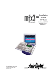
Pictorial guide to the Pedion
1
6
7
8
2
3
1/2
9
10
4
11
5
12
Welcome
OWNER’S HANDBOOK
1
LCD panel
2
1
Num Lock light
A
Caps Lock light
Scroll Lock light
3
PC Card Slot 0 (CardBus/Zoomed Video)
4
PC Card Slot 1 (CardBus)
5
Emergency OFF hole (if the Pedion stalls, insert
a non-metallic probe such as a pencil tip)
6
Power button
7
Power Status light
The Power button alternately turns on the Pedion
and puts it into Disk Suspend mode.
Power Status light is green when the Pedion is
The
working normally, orange in Memory Suspend mode,
and unlit when the Pedion is shut down or in Disk
Suspend mode.
The
Battery Status light is green when the
internal battery is fully charged, orange when it is
recharging, and unlit when the Pedion is running on
battery power.
For more information about the Pedion’s powersaving modes, see the chapter on “Battery & Power
Management”.
Battery Status light
Hard disk activity light
8
Speaker (mono)
9
Touchpad
10 Microphone (mono)
11 Right touchpad button
12 Left touchpad button
Welcome
1/3
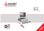
OWNER’S HANDBOOK
2
1
3
4
6
7
1/4
Welcome
5
1
DC-IN connector (for AC adapter)
2
Security notch (for attaching an anti-theft chain)
3
Infrared communication port
4
USB port (behind protective rubber cover)
5
Audio output jack (stereo)
6
Battery connector (cover closed)
7
Multimedia connector (cover closed)
OWNER’S HANDBOOK
Pictorial guide to the Multimedia Pack
By attaching the Multimedia Pack to your Pedion,
you can use diskettes and CD-ROMs, and connect
various peripheral devices.
Caution
Do not open the battery connector cover on the underside
of the Pedion unless you intend to install either the
Multimedia Pack (or the Battery Pack) straight away.
Note
You must shut down the Pedion before attaching or
removing the Multimedia Pack.
Welcome
1/5
OWNER’S HANDBOOK
1
2
3
4
5
6
1
Stereo speaker (left)
2
Line/microphone input jack
3
Audio output jack (stereo)
4
Diskette (floppy disk) drive
5
Diskette eject button
6
Pedion release lever
7
CD tray
8
CD eject button
9
CD activity light
10 CD emergency eject hole
11 Stereo speaker (right)
7
12 Security notch (for attaching an anti-theft chain)
8
17
9
10
15
14
11
13
12
18
13 Keyboard port
16
14 Mouse port
15 Serial port
16 Parallel port
17 Monitor port
18 USB port
1/6
Welcome
OWNER’S HANDBOOK
To attach the Multimedia Pack
1.
Shut down the Pedion.
2.
Close the LCD panel and turn the Pedion over.
3.
Slide open the battery and multimedia
connector covers on the underside of the
Pedion.
5.
Gently press down on the front edge of the
Pedion until it clicks into place. Do not use
excessive force.
To remove the Multimedia Pack
4.
Align the two small holes on the rear of the
Pedion with the two raised catches on the rear
edge of the Multimedia Pack.
1.
Remove any CD or diskette from the drives.
2.
Shut down the Pedion.
3.
Close the LCD panel.
4.
Slide the lever on the front of the Multimedia
Pack to the left, then lift the Pedion off the
Multimedia Pack (front edge first).
5.
Turn the Pedion over and close the multimedia
and battery connector covers on the underside.
Welcome
1/7
OWNER’S HANDBOOK
Backing up the pre-installed software
Creating an emergency startup disk
We strongly recommend that you create an emergency
startup disk. This will enable you to start Windows in
the event of your existing Windows software
becoming corrupted.
1.
On the Start menu, point at Settings, then click
Control Panel.
2.
In the Control Panel, double click the
Add/Remove Programs icon.
3.
On the Startup Disk tab of the Add/Remove
Programs Properties dialog, click Create Disk.
4.
Insert a formatted, 1.44 Mbyte diskette into the
diskette drive. Follow the on-screen instructions.
Backing up your system
We also recommend that you copy or ‘back-up’
Windows and any other pre-installed software soon
after setting up the system. This is particularly
important for systems supplied without installation
disks for the software on the hard disk. A back-up
1/8
Welcome
copy will safeguard the pre-installed software against
loss if the hard disk fails or if you accidentally
overwrite or delete files.
The Microsoft Create System Disks utility
allows you to create installation diskettes from
disk images pre-installed on the hard disk.
To back up other pre-installed software (and
your own files) use the Backup tool. Click the
Start button in the Windows taskbar, then
Programs, Accessories, System Tools and
Backup.
In general, any copy you make of pre-installed
software must be used only as a back-up copy, in case
the pre-installed version is lost. You are not allowed to
use installation diskettes created from disk images to
install the software onto another computer.
OWNER’S HANDBOOK
General advice
As a portable computer, this machine is designed to
be used in various environments. The following
paragraphs contain guidelines in caring for yourself
and your computer.
Place the computer on a firm, level surface if
possible, away from vibration.
Use the computer away from moisture, direct
sunlight, and extremes of heat and cold. Avoid
situations in which the surrounding temperature
or humidity may change rapidly. When the
computer is in use, the temperature should be
o
between 10 and 35 C and humidity between
20% and 80% (with no condensation).
Ensure that you maintain a healthy posture
when using the computer. Ideally, your feet
should be on the floor and your legs at right
angles, with your upper legs approximately
horizontal. Your back should be kept straight,
and your elbows should be about the same
height as the keyboard. Also, your eyes should
generally be approximately 0.5m from the
display, with the top of the screen as close to
your direct line of vision as possible.
0.5m
In winter, moving the computer from outdoors
to the warm indoors can cause moisture to
condense inside the system. Allow time for the
computer to dry out before turning it on.
Make sure there is adequate space around the
computer for ventilation.
Always handle the computer gently.
Welcome
1/9
OWNER’S HANDBOOK
1/10
Avoid using the computer when placed directly
on your lap for long periods. It can generate
enough heat to cause low-temperature burns.
(redness or blisters)
When positioning the computer, take into
account any local or national regulations relating
to ergonomic requirements. For example, you
should ensure that little or no light is reflected
off the screen as glare, and that the keyboard is
placed in a comfortable position for typing.
You should be aware that in some places, the use
of a portable computer is strictly forbidden. For
example, you should check before using your
portable computer inside a hospital, or before
boarding an aircraft.
Make sure that any sensitive information on
your computer is protected by using access
passwords.
Keep the computer away from strong magnetic
fields, such as stereo speakers.
Do not use the computer near liquids or
corrosive chemicals
Welcome
Ensure all cables, particularly power cords, do
not trail across the floor where people walking
past can snag them.
Keep the computer unit clean, using a nonabrasive cloth.
OWNER’S HANDBOOK
2
TOUCHPAD & KEYBOARD
Using the touchpad
The touchpad consists of a touch-sensitive tablet and
two buttons, which together perform the same
function as a mouse. The left and right touchpad
buttons correspond to left and right mouse buttons.
Touchpad gestures
The basic touchpad gestures are as follows
How to use the touchpad
Touch the tablet only with your finger tip.
Don’t use your fingernails or a pen, or wear a
glove.
Touch only one place on the tablet’s surface.
Touching two or more places at the same time
confuses the software.
Tapping the tablet’s surface acts like clicking a
left mouse button.
Caution
Don’t use the touchpad if your fingers are wet. Don’t
press too hard on the tablet’s surface; you could break it
or hurt yourself.
To move the cursor: Slide your finger tip across
the surface of the tablet. To move the cursor a
large distance, move your finger in the required
direction several times in succession. Only slight
movement is needed for more accurate
positioning of the cursor.
To left-click: Tap once with your finger tip.
To double-left-click: Tap twice with your finger
tip.
To click-and-drag: Tap twice, but hold your
finger on the tablet’s surface on the second tap,
then slide your finger tip across the tablet’s
surface.
Touchpad & Keyboard
2/1
OWNER’S HANDBOOK
Mouse Properties
Double-click the Touchpad icon in the Windows
taskbar to open the Mouse Properties dialog.
Touchpad icon
You can use this dialog to configure many additional
features of the touchpad. For example, you can add a
tapping gesture that mimics a right-click.
For more information, click the Help button in the
Mouse Properties dialog.
2/2
Touchpad & Keyboard
OWNER’S HANDBOOK
Using the keyboard
The Pedion’s keyboard works just like a full-sized
computer keyboard, but some keys have additional
functions.
Blue numeric keypad
Locking keys
When you press any key on the numeric keypad with
the Shift key held down, the definition of that key
changes to a cursor control key, as shown below.
The keyboard has some locking keys whose status is
indicated by the lights on the upper left edge of the
computer.
Num Lock. Press the NL/SL key to turn on
numeric locking. With the Num Lock light on,
the keys marked in blue on the keyboard work
as a numeric keypad.
Caps Lock. Press the Caps Lock key to turn on
capitals locking. With the Caps Lock light on,
the characters you type are displayed in
uppercase.
Scroll Lock. Hold down the Fn key then press
the NL/SL key to turn on scroll locking. The
effect usually depends on the specific software
you are using.
When the 1 Num Lock light is on, you can type the
numerals or symbols marked in blue.
Home
^
&
6
7
Y
*8
7
U
(
H
O
P
5
6
K
J
1
PgUp
0
9
I
4
End
)
9
8
L
2
3
:{
;
PgDn
When the Num Lock light is on, pressing any key on
the numeric keypad with the Fn key held down allows
you to type the normal character associated with that
key (that is, as if the Num Lock light were off).
Touchpad & Keyboard
2/3
OWNER’S HANDBOOK
2/4
Orange function keys
Windows keys
Some keys have additional functions, marked in
orange. Hold down the Fn key while pressing the
required “orange” key to access these functions.
The keyboard has two keys dedicated to Windows
functions: the
Windows logo key (WIN) and the
Application key (APP).
Fn + F2
Backslash “\” character. (Shift + Fn + F2
produces the vertical bar “|” character.)
WIN
Opens the Start menu.
WIN + Tab
Fn + F9
Increases the brightness of the screen.
Fn + F8
Decreases the brightness of the screen.
Makes applications active in the
order they are indicated on the task
bar.
Fn + F10
Turns audio output on and off.
WIN + E
Activates Windows Explorer.
WIN + F
Starts the Find function (equivalent
to Start, Find, Files or Folders).
WIN + M
Minimises all windows (Shift + WIN
+ M restores all windows).
WIN + R
Starts the Run function (equivalent
to Start, Run).
APP
Displays a context menu (as if you
had clicked the right-hand touchpad
or mouse button).
Touchpad & Keyboard
OWNER’S HANDBOOK
3
DISKETTE, CD-ROM & AUDIO
Using the diskette (floppy disk) drive
You can use either 1.44 Mbyte (2HD) or 720 Kbyte
(2DD) 3.5-inch diskettes in the Multimedia Pack’s
diskette drive.
Advice on handling diskettes
Never touch the disk surface beneath the metal
shutter.
Keep diskettes away from dust, direct sunlight,
heat, moisture, high humidity, magnetic objects
and electrical equipment that may generate
magnetic fields.
Write on the disk label before you attach it to the
diskette, or use a soft felt-tip pen. Make sure the
label fits within the slightly recessed area on the
face of the diskette.
Note
Do not place a diskette on top of the Pedion’s internal
speaker. The magnetic field from the speaker can damage
the data on the diskette
Diskette, CD-ROM & Audio
3/1
OWNER’S HANDBOOK
To insert a diskette
To write-protect a diskette
Push the diskette into the drive, metal shutter
foremost, and with the label side facing
upwards, until it clicks into place.
To eject a diskette
1.
Ensure that the diskette activity light is off.
2.
Press the diskette eject button.
If a diskette becomes stuck in the drive, perhaps
because its label has peeled back, do not attempt to
remove it with tweezers or any similar implement; you
risk damaging the drive. Call an authorised
maintainer.
3/2
Diskette, CD-ROM & Audio
Slide the small plastic tab on the reverse of the
diskette to uncover the hole beneath it.
You can read, copy or print the files on a writeprotected diskette, but you cannot create,
rename or delete any files.
OWNER’S HANDBOOK
Using the CD-ROM drive
You can use either audio or data compact discs (CDs)
in the Multimedia Pack’s CD-ROM drive.
Advice on handling CDs
Make sure the CD drive is empty before turning
off the Pedion.
Avoid touching the disc’s surface. Hold the CD
by its edges.
Keep CDs away from direct sunlight, heat,
humidity, dust and moisture.
To clean a CD, wipe the surface radially
outwards from the centre using a soft cloth. Do
not use any cleaning agent.
Warning
The CD-ROM drive contains a laser system which is
harmful to the eyes if exposed. Do not attempt to
disassemble the CD-ROM drive; if a fault occurs, call an
authorised maintainer.
Caution
Do not attempt to use the Windows CD player program
while a data CD-ROM is in the drive. This may
damage your ears or the speakers.
Note
Do not move or nudge the Pedion while a CD is in the
drive, particularly while the CD activity light is on. This
can damage the CD or the drive.
Diskette, CD-ROM & Audio
3/3
OWNER’S HANDBOOK
To load a CD
To remove a CD normally
1.
Turn on the Pedion.
1.
2.
Press the CD eject button. The CD tray comes
out about 1.5 cm.
Ensure that the Pedion is turned on and that the
CD activity light is off.
2.
Press the CD eject button.
3.
Pull the CD tray out to its fullest extent.
4.
Set the CD on the CD tray, with the label side
uppermost. Press down on the CD gently but
firmly so that it is held securely in position.
5.
3/4
Push in the CD tray until it clicks into place.
The CD activity light flashes as the drive comes
up to speed.
Diskette, CD-ROM & Audio
To remove a CD when there is no
power
1.
Ensure that the Pedion is turned off.
2.
Insert a thin non-metallic probe, such as a pencil
tip, into the CD emergency eject hole. The CD
tray comes out about 1.5 cm.
OWNER’S HANDBOOK
Using the audio features
The Pedion has a 3.5 mm stereo mini-jack for audio
output, plus an internal microphone and mono
speaker.
The Multimedia Pack has a line/microphone input
and a stereo audio output jack, plus internal stereo
speakers.
If the Pedion is docked with the Multimedia Pack, the
Pedion’s audio output jack and internal speaker are
automatically disabled.
To extend the stereo speakers
Press gently on the left speaker to release it, then pull
it out. Repeat for the right speaker.
Diskette, CD-ROM & Audio
3/5
OWNER’S HANDBOOK
Audio input
The line/microphone input jack on the Multimedia
Pack can accept input from a cassette, CD, mini-disk
or DAT player, hi-fi equipment or a self-powered
microphone.
When using an external self-powered microphone,
you must enable the line-in input for recording and
disable the (internal) microphone, as follows:
1.
Double-click the Loudspeaker icon in the
taskbar to open the Volume Control dialog.
2.
From the Options menu, click Properties.
3.
Select Recording, and make sure that the
Line-In option is ticked. Click OK.
4.
Make sure the Microphone Balance Select
option is not ticked.
Audio output
The audio output jack on the Pedion or the
Multimedia Pack can be used to connect cassette,
mini-disk or DAT recorders, headphones, selfpowered speakers, or hi-fi equipment.
3/6
Diskette, CD-ROM & Audio
When anything is attached to an output jack, the
system’s speakers are muted automatically.
TEAC CD Player
The TEAC CD player program is pre-installed on the
Pedion’s hard disk as an alternative to the Microsoft
CD Player.
Click Start, point at Programs, Teac CD
Player, then click CD Player 95.
For more information, refer to the player’s on-line
help.
OWNER’S HANDBOOK
4
BATTERY & POWER MANAGEMENT
Using battery power
The Pedion can operate from its internal battery for
up to 1.8 hours, depending on the programs you are
running and how much use you make of the hard disk
and CD-ROM drive.
An optional Battery Pack can be attached to the base
of either the Pedion or the Multimedia Pack,
extending the operating time to up to 7.2 hours.
You can recharge the internal battery and the Battery
Pack 300 to 500 times before their performance starts
to degrade. At this point you should contact your
Mitsubishi Electric PC dealer or maintainer.
General advice
At first, the internal battery is not charged.
Before using your Pedion for the first time, you
must charge the battery. The same applies to the
optional Battery Pack.
A new battery may be discharged in an
unexpectedly short time. Fully recharge it before
using it again.
You should recharge and discharge fully each
time. Partial recharges/discharges will shorten
the battery’s lifetime.
Extreme temperatures (high or low) will shorten
the battery’s lifetime.
Neither the Pedion’s internal battery nor the
batteries in the Battery Pack can be removed. If
they become worn out, contact your Mitsubishi
Electric PC supplier.
Battery & Power Management
4/1
OWNER’S HANDBOOK
Recharging the internal battery
The Pedion’s internal battery begins to recharge as
soon as you connect the Pedion to the AC power
supply.
The Pedion’s Battery Status light
is orange while
the battery is recharging, green when it is recharged.
The time to recharge depends on the method you use:
Recharge (while working) ............................12 hours
Recharge (while turned off) ...........................3 hours
Checking the battery level (1)
You can quickly check the battery level by positioning
the cursor over the Battery Meter icon on the
Windows taskbar. A “tool-tip” appears showing the
amount of battery life remaining, expressed either in
time or as a percentage of full charge. (The Battery
Meter icon looks like a battery when the Pedion is on
battery power, or like a power cord when the Pedion
is connected to the AC power supply.)
Battery Meter icons
4/2
Battery & Power Management
If you want more information, you can double-click
the icon to open the Battery Meter dialog.
OWNER’S HANDBOOK
Low-battery warning
Windows displays a low-battery warning when the
battery is almost exhausted. The Pedion switches to
Disk Suspend mode about three minutes later.
When you see a low-battery warning, you should
immediately connect the AC adapter. If the AC
adapter is not available, you must shut down the
Pedion until it is.
4.
Align the two small holes on the rear of the
Pedion (or Multimedia Pack) with the two
raised catches on the rear edge of the Battery
Pack.
To attach the optional Battery Pack
5.
Slide apart the two latches on the front of the
Battery Pack and gently press down on the front
edge of the Pedion until it clicks into place. Do
not use excessive force.
1.
Shut down or suspend the Pedion.
2.
Close the LCD panel and turn the system over.
3.
Slide open the battery connector cover on the
underside of the Pedion (or Multimedia Pack).
Caution
Do not open the battery connector cover on the
underside of the Pedion or Multimedia Pack unless
you intend to install the Battery Pack straight
away.
Battery & Power Management
4/3
OWNER’S HANDBOOK
To remove the Battery Pack
1.
If the Multimedia Pack is attached, remove any
CD or diskette from the drives.
2.
Shut down or suspend the Pedion.
3.
Close the LCD panel.
4.
Slide apart the two latches on the front of the
Battery Pack, then lift the Pedion off the Battery
Pack.
5.
Turn the system over and slide closed the
battery connector cover on the underside of the
Pedion (or Multimedia Pack).
Recharging the Battery Pack
If the Battery Pack is attached to the Pedion (or
Multimedia Pack), it will begin to recharge as soon as
you connect the Pedion to the AC power supply. In
fact the Battery Pack will recharge first, followed by
the Pedion’s internal battery.
If the Battery Pack is separated from the Pedion, it
can be recharged by connecting the AC adapter to it
directly (see diagram).
4/4
Battery & Power Management
The Battery Pack’s Charge Status light
is orange
while the pack is recharging, green when it is
recharged. The time to recharge depends on the
method you use:
Recharge via Pedion (while working)...........30 hours
Recharge via Pedion (while turned off) ..........8 hours
Recharge directly via AC adapter ...................8 hours
Important
You must not connect the AC adapter to the Battery
Pack while the pack is attached to the Pedion or
Multimedia Pack.
OWNER’S HANDBOOK
Checking the battery level (2)
Pressing the Battery Level button on the right-hand
side of the Battery Pack illuminates a row of four
battery level indicators. The number of indicators lit
shows the current battery level: four indicators means
100% charge, three: 75%, two: 50%, one: 25%, and
no indicators lit means the pack is discharged.
If the Battery Pack is attached to the Pedion, you can
check the battery level with the Battery Meter, as
described earlier in this chapter. If the Show the
status of all batteries option is ticked, the Battery
Meter shows the levels of the internal battery and the
Battery Pack separately.
2
1
3
1
Charge Status light
2
Battery level indicator lights
3
Battery Level button
Battery & Power Management
4/5
OWNER’S HANDBOOK
Options for power management
The Pedion has several modes that can be used to
conserve power.
The Pedion can also suppress power to components
that are idle or unused for longer than a certain
interval. This includes the keyboard, touchpad, hard
disk, LCD panel, audio system, and peripherals
connected to the serial or parallel ports.
Disk Suspend mode
To enter Disk Suspend mode, press the Power
button, or choose Suspend from the Windows Start
menu. To resume, press the Power button again.
In this mode, your unsaved work and the Windows
environment are first saved onto a special area of the
hard disk, then the Pedion is turned off. It takes about
30 seconds to save the system, and 30-50 seconds to
restore it.
With BIOS Setup, you can configure the Pedion to
enter Disk Suspend mode after a specified period of
inactivity.
4/6
Battery & Power Management
Memory Suspend mode
To enter Memory Suspend mode, close the LCD
panel. To resume, open the LCD panel and press the
Power button.
In this mode, your unsaved work and the Windows
environment are kept in the Pedion's memory. This
mode uses more power than Disk Suspend, but you
can resume working in only a few seconds.
“Energy Star” energy-saving features
The Display Properties of the LCD panel can be
configured under Windows to suppress or shut off
power to the LCD panel after specified periods of
inactivity. The Pedion arrives with these features
turned off.
Note
As an Energy Star partner, Mitsubishi Electric
Corporation has determined that this product meets the
international Energy Star program for energy efficiency.
OWNER’S HANDBOOK
Disk drive low power mode
Idle mode
The Power Properties of the hard disk can be
configured under Windows to suppress power after
specified periods of inactivity, depending on whether
or not the Pedion is running from the AC power
supply or its own batteries. The Pedion arrives with
these timeouts set to 30 and 3 minutes respectively.
The Pedion can slow its Pentium processor during
brief periods when the system is not busy.
Standby mode
The Pedion can automatically suppress power to idle
components, including the LCD panel, after a
specified period of inactivity. To restore the system,
press any key or use the touchpad.
The Pedion arrives with this feature turned off. If you
want to use it, you must set a Standby timeout period
with the BIOS Setup utility.
The Pedion arrives with this feature turned off. If you
want to use it, you must enable it with the BIOS
Setup utility.
Hard Disk and Video Timeouts
The Pedion can suppress power to the hard disk and
the LCD panel after specified periods of inactivity.
The Pedion arrives with the hard disk inactivity
timeout set to 1 minute and the video (LCD) timeout
disabled. You can change these settings with the BIOS
Setup utility.
Note for Windows NT users
Neither Disk Suspend nor Memory Suspend mode should
be attempted with Windows NT.
Battery & Power Management
4/7
OWNER’S HANDBOOK
More about Disk Suspend mode
In Disk Suspend mode your unsaved work and the
Windows environment are written to the Pedion’s
hard disk before the power is turned off. A special
area of the hard disk is reserved for this purpose.
While in this mode, the Power Status light is unlit.
It can take up to 30 seconds to write the information
onto the hard disk. Do not press the Power button
during this time or move the Pedion before it has
turned itself off.
You can enter Disk Suspend mode manually
whenever you want to. With BIOS Setup, you can
also configure the Pedion to enter Disk Suspend
mode after a specified period of inactivity (the “Auto
Suspend timeout”).
The Pedion automatically enters Disk Suspend mode
three seconds after a low-battery warning.
To enter Disk Suspend mode
1.
Press the Power button or choose Suspend from
the Windows Start menu.
2.
Wait until the Pedion’s Power Status light
goes out.
Caution
Do not use a disk compression utility such as DriveSpace.
It will cause the Disk Suspend operation to fail.
Holding down the Power button for more than three
seconds puts the Pedion into an abnormal state. If you
press the Power button again, the system will be restarted
and any unsaved work will be lost.
Note
The function of the Power button can be changed with
the BIOS Setup utility.
Pedion cannot go into Suspend mode while the Infrared
Monitor is searching for infrared devices.
Do not use Suspend mode when connected to a network;
the system may not resume correctly.
4/8
Battery & Power Management
OWNER’S HANDBOOK
To restore the system from Disk
Suspend mode
Press the Power button (if there has been a lowbattery warning, connect the AC adapter first).
To set up an Auto Suspend timeout
1.
Start the Setup utility.
2.
Select the Power Saving menu.
3.
Set Power Management to “Customized”.
4.
Make sure that Suspend Mode is set to “Save
To Disk”.
5.
Set the Auto Suspend Timeout to the desired
value.
6.
Exit the Setup utility, saving changes.
To change the function of the Power
button
Normally, pressing the Pedion’s Power button puts
the system into Disk Suspend mode. You can change
the function of the Power button so that it either
turns the Pedion on and off or causes Memory
Suspend mode instead.
1.
Start the Setup utility.
2.
Select the Power Saving menu.
3.
To make the Power button turn the Pedion on
and off, set Switch Button to “On/Off”.
Otherwise, leave it set to “Sus/Res”.
4.
To make the Power button put the Pedion in
Memory Suspend mode, set Suspend Mode to
“Suspend”. For Disk Suspend mode (the default
setting), set it to “Save To Disk”.
5.
Exit the Setup utility, saving changes.
For more information, refer to the chapter on “BIOS
Setup”.
Battery & Power Management
4/9
OWNER’S HANDBOOK
More about Memory Suspend mode
In Memory Suspend mode your unsaved work and
the Windows environment are written to the Pedion’s
memory before the power is suppressed. While in this
mode, the Power Status light is orange.
To enter Memory Suspend mode
You can enter Memory Suspend mode manually,
simply by closing the LCD panel.
To restore the system from Memory
Suspend mode
Note
The function of the Power button can be changed with
the BIOS Setup utility (see previous page).
Pedion cannot go into Suspend mode while the Infrared
Monitor is searching for infrared devices.
If the Resume On Modem Ring or Resume On Time
options are enabled in the BIOS Setup utility, the system
can resume automatically, either on serial port activity
(not PC Card modem) or at a specified time.
Do not use Suspend mode when connected to a network;
the system may not resume correctly.
4/10
Battery & Power Management
Close the LCD panel (without first pressing the
Power button).
Press the Power button.
OWNER’S HANDBOOK
5
CONNECTING OPTIONAL DEVICES
It is possible to connect various optional devices,
either directly to the Pedion or to the Multimedia
Pack. This chapter provides advice on the types of
devices that can be connected, and how to connect
them.
Suspend or shut down?
In some cases, you must suspend or shut down the Pedion
before connecting an optional device. The procedure for
the device in question makes this clear.
PC Cards (also called PCMCIA cards)
Infrared devices
Universal Serial Bus (USB) devices
Printer (or some other parallel port device)
Serial port device
External keyboard or numeric keypad
Mouse
External colour monitor
Connecting optional devices
5/1
OWNER’S HANDBOOK
Installing a PC Card
There are two PC Card slots on the left side of the
Pedion. Each slot can accommodate either a Type I
(3.3 mm) or a Type II (5.0 mm) card.
Slot 0 (towards the rear) can accept PC Cards with
either CardBus or Zoomed Video (ZV) functions;
Slot 1 accepts CardBus only.
To install a PC Card
1.
Hold the PC Card with the logo side facing up.
2.
Insert the PC Card carefully into the chosen
slot.
3.
When the slot’s eject button pops out, fold it
back into its recess on the side of the Pedion.
CardBus is the 32-bit version of PC Card
technology. CardBus allows speeds of up to 133
Mbps at 33 MHz.
Zoomed Video allows the PC Card to write
unbuffered data directly to the Pedion’s video
controller.
Note for Windows NT users
You must shut down the Pedion before inserting or
removing a PC Card when using Windows NT.
CardBus and Zoomed Video cards cannot be used with
Windows NT 4.0.
5/2
Connecting optional devices
OWNER’S HANDBOOK
The two eject buttons fold in different
directions.
To remove a PC Card
1.
Follow the procedure for terminating card
operations under Windows.
2.
Fold the slot’s eject button out of its recess, then
push it firmly.
1
2
4.
Connect any necessary cable to the PC Card.
2
1
3.
Pull the PC Card completely out of the slot.
The PC Card may become hot. This is normal and
not a problem.
5.
Configure the PC Card software.
Connecting optional devices
5/3
OWNER’S HANDBOOK
Connecting an infrared device
The Pedion can use the same kind of infrared signal
as that used by a TV or video remote control to
communicate with another computer or peripheral
device. The Pedion supports the IrDA 1.0 and IrDA
1.1 Fast Infrared (FIR) standards promoted by the
Infrared Data Association.
When using the infrared port, it is important to
ensure that the two devices about 1 metre apart and
within an angle of 15 degrees of a clear line-of-sight
between the two ports.
IR device
15
15
1m
Pedion
IR port
5/4
Connecting optional devices
General advice on IR communication
Communication is one-to-one only.
Communication under a fluorescent lamp may
decrease the speed of data transfer.
Keep TV or VCR remote controls away from
the effective range of the infrared ports.
During communication, do not move the two
communicating devices.
The Pedion is configured at the factory to use
the IrDA 1.0 standard. If necessary, you can
change this to Fast Infrared with the BIOS
Setup utility and the Windows Control Panel.
OWNER’S HANDBOOK
Infrared Monitor
An Infrared Monitor program is provided to help you
keep track of the Pedion’s infrared activity. The
Infrared Monitor can normally be opened by doubleclicking the Infrared icon in the Windows taskbar.
Infrared icon
The default settings of the Infrared Monitor ensure
that the Pedion searches for infrared devices within
range every 3 seconds. If a suitable device is found,
and provided that it is Plug and Play aware, its
associated software can be installed automatically and
communication can begin.
With the Infrared Monitor, you can:
Find out what infrared devices are within range.
Find out if the Pedion is currently
communicating with an infrared device, and if it
is, how well it is communicating.
Control how Infrared Monitor reports status on
the infrared activity it detects.
For more information, click the Help button in the
Infrared Monitor dialog.
Decide what type of infrared activity to allow.
Connecting optional devices
5/5
OWNER’S HANDBOOK
To display the Infrared icon
To change to Fast Infrared mode
Follow this procedure if the Infrared icon is not
present in the Windows taskbar.
1.
Start the BIOS Setup utility.
2.
Select the Advanced menu.
3.
Select the I/O Device Configuration sub-menu.
4.
Change the Mode option of Serial Port B to
“FIR”.
5.
Exit the Setup utility, saving changes.
1.
Click the Start button in the Windows taskbar,
point at Settings and then click Control Panel.
2.
Double-click the Infrared icon.
3.
Click the Preferences tab.
4.
Make sure that Display the infrared icon in the
taskbar is ticked.
When Windows restarts, it detects the change in
configuration and starts the Update Device
Driver wizard.
To turn off searching
The Pedion cannot go into Suspend mode while the
Infrared Monitor is searching for infrared devices.
1.
Right-click the Infrared icon in the Windows
taskbar.
2.
Make sure that Search for devices in range is
not ticked.
6.
Click Next to search for updated drivers, then
click Other Locations.
7.
In the Select Other Locations dialog, type
c:\windows\options\cabs and then click OK.
8.
Click Finish. (If the Welcome To Windows
dialog appears, close it.)
9.
Click the Start button in the Windows taskbar,
point at Settings and then click Control Panel.
10. Double-click the Add New Hardware icon.
5/6
Connecting optional devices
OWNER’S HANDBOOK
11. In the Add New Hardware wizard, click Next.
12. Click No in answer to the question “Do you
want Windows to search for your new
hardware?”, and then click Next.
13. Select the Infrared entry in the Hardware Types
list, and click Next.
14. In the Add Infrared Device wizard, click Next,
and then click Have Disk. In the Install From
Disk dialog, type c:\windows\options\cabs and
then click OK.
15. Make sure that the Add Infrared Device wizard
shows the infrared device model as (FIR) Built-in
Infrared port on laptop or desktop, and then
click Next.
16. Select Fast Infrared Communications Port
(COM2), click Next twice, and then click
Finish.
17. In the Control Panel, double-click the Infrared
icon.
18. On the Identification tab, type a suitable
computer name and description, and then click
OK.
19. Click Yes to restart the Pedion.
When Windows restarts, follow the procedure given
earlier in this chapter to display the Infrared icon in
the taskbar.
Connecting optional devices
5/7
OWNER’S HANDBOOK
Connecting a USB device
The Pedion and the Multimedia Pack each have one
USB (Universal Serial Bus) port. If the Pedion is
docked with the Multimedia Pack, both ports can be
used simultaneously.
To connect a USB device
About the Universal Serial Bus (USB)
1.
The USB is a relatively new way of connecting
peripherals to your computer. It has several
advantages over existing serial and parallel ports.
If connecting to the Pedion, peel back the
rubber cover from the USB port.
2.
Plug the USB cable into the USB port on the
Pedion or the Multimedia Pack.
Several USB devices can be “daisy-chained”
together.
USB devices are “hot-pluggable”; that is, they
can be plugged in and disconnected without
turning off the computer.
The USB can supply DC power to certain
devices, so that they do not need an independent
power supply.
USB is also quite fast, operating at 12 megabits per
second, which is appropriate for a wide range of
applications including video conferencing cameras.
5/8
Before connecting any USB device, we recommend
that you read all documentation provided with the
device.
Connecting optional devices
Windows should automatically recognise the USB
device.
OWNER’S HANDBOOK
Connecting a printer (or other parallel port device)
You can connect a printer to the parallel port of the
Multimedia Pack.
The Pedion arrives with the parallel port is set to BiDirectional mode. Extended Capabilities Port (ECP)
and Enhanced Parallel Port (EPP) functionality is also
supported, and can be configured with the BIOS
Setup utility.
To connect a printer
1.
Shut down the Pedion.
2.
Plug the printer cable into the parallel port on
the rear of the Multimedia Pack. Tighten both
the screws to secure the connection.
3.
Connect the printer cable to the printer as
described in the printer’s manual.
4.
Turn on the printer.
5.
Turn on the Pedion.
ECP is good at transferring big blocks of data
quickly (e.g. scanners, printers). The parallel
port in ECP mode uses a DMA channel.
EPP is good for links that switch directions
frequently (e.g. drives).
Note
When disconnecting a parallel port device, turn off the
printer before shutting down the Pedion.
Connecting optional devices
5/9
OWNER’S HANDBOOK
Connecting a serial port device
5/10
You can connect a device such as a modem or barcode
scanner to the serial port of the Multimedia Pack.
To connect a serial device
1.
Shut down the Pedion.
Note
When disconnecting the serial device, turn off the device
before you shut down the Pedion.
2.
Plug the serial cable into the serial port on the
rear of the Multimedia Pack. Tighten both the
screws to secure the connection.
3.
Connect the serial cable to the device as
described in the device’s manual.
4.
Turn on the serial device (if applicable).
5.
Turn on the Pedion.
Connecting optional devices
OWNER’S HANDBOOK
Connecting an external keyboard or mouse
To connect a keyboard
To connect a mouse
1.
Shut down the Pedion.
1.
Shut down the Pedion.
2.
Plug the keyboard (or numeric keypad) into the
keyboard port on the rear of the Multimedia
Pack.
2.
Plug the mouse into the mouse port on the rear
of the Multimedia Pack.
3.
Turn on the Pedion.
3.
Turn on the Pedion.
Note
Before disconnecting a keyboard or mouse, shut down the
Pedion.
Note
When a mouse is connected, the touchpad doesn't work.
Connecting optional devices
5/11
OWNER’S HANDBOOK
Connecting an external monitor
You can connect an external colour monitor to the
monitor port of the Multimedia Pack.
To connect a monitor
1.
Shut down the Pedion.
Note
The screen resolution and refresh rate of the LCD panel
must be supported by the external monitor.
2.
Plug the monitor’s signal cable into the monitor
port on the rear of the Multimedia Pack.
3.
Tighten both the screws to secure
connection. Turn on the monitor.
4.
Turn on the Pedion.
5.
Click Start, point at Settings, then click Control
Panel.
6.
Double-click the Display icon to open the
Display Properties dialog.
When disconnecting the monitor, turn off the monitor
before shutting down the Pedion.
5/12
Connecting optional devices
the
OWNER’S HANDBOOK
7.
Click the NeoMagic tab.
8.
Click Display Options.
9.
Select Monitor, LCD Panel or Monitor/LCD
according to whether you want to display
Windows on the external monitor, the LCD
panel, or both at the same time.
Connecting optional devices
5/13
OWNER’S HANDBOOK
5/14
Connecting optional devices
OWNER’S HANDBOOK
6
BIOS SETUP
Using the Setup utility
The BIOS (Basic Input/Output System) mediates
between the computer’s hardware – the processor,
memory, and so on – and its software – the operating
system and your programs. The BIOS program is kept
in permanent, read-only memory or ROM.
Whenever the computer is turned on, the BIOS
power-on self-test (POST) routine tests various
hardware components, including memory, and
compares the actual configuration of the computer
with that recorded in permanent (CMOS) memory.
Setup is a helpful utility that forms part of the BIOS
program. It allows you to view and alter the
computer’s hardware configuration. Configuring the
computer may be necessary to ensure that the software
you use can recognise and exploit the hardware’s
capabilities.
Using the Setup utility is fairly straightforward; all of
the options and control keys available are constantly
displayed at the bottom of the screen, and there is
item-specific help displayed on the right of the screen
for whichever item is currently selected.
The current configuration is kept in a special area of
memory, called CMOS memory, and maintained by a
battery so that the configuration is preserved even
while the computer is switched off.
Your computer arrives already configured, but may
need to be configured again in certain circumstances.
The Setup utility contains the following main menu
screens:
Main
Advanced
Security
Power Saving
Exit
BIOS Setup
6/1
OWNER’S HANDBOOK
There are many parameters which can be changed in
the Setup utility. These can easily be reviewed by
browsing through the Setup utility itself, and are
therefore not covered in detail here.
If Setup starts on its own
Setup might start on its own for the following reasons:
Getting help in Setup
You can get general help about the control keys at any
time by pressing the F1 key.
The Help window on the right-hand side of each
screen displays help text for the currently-selected
field. It changes as you move the cursor from one field
to another.
To start the Setup utility
6/2
1.
Turn on or restart the Pedion.
2.
Wait until the “Pedion Mobile Computer” logo
appears on the screen.
3.
Press the F2 key.
4.
If you have previously defined a Supervisor
password, you are prompted for it before Setup
starts.
BIOS Setup
The power-on self-test (POST) detects a
configuration error or fault. This may be
signalled by one or more POST error messages.
If a persistent fault is indicated, make a note of
any error messages and the current Setup
configuration settings before calling an
authorised maintainer.
The CMOS battery may be running down. This
may cause spurious POST error messages. If this
happens every time you turn on the computer,
you may have to change the battery. Contact
your Mitsubishi Electric PC supplier or
maintainer to have the CMOS battery renewed.
OWNER’S HANDBOOK
Press
To
Control keys
F1 or Alt-H
View a general help topic. Press Esc to
close the help window.
Use the keys listed in the legend bar at the bottom of
the Setup screen to make your selections or exit the
current menu.
Esc
Exit the current menu.
Left or Right arrow
Select a different menu.
Up or Down arrow
Select fields on the current menu.
Plus (+) or F6 or Spacebar
Select the next value for the current field.
Minus (–) or F5
Select the previous value for the current
field.
Enter
Execute a command or enter a submenu.
Home or End
Move the cursor to the top or bottom of
the current menu.
PgUp or PgDn
Move the cursor to the next or previous
page of the current menu.
F9
Restore the default settings for all menus
(this does not restore the original factory
settings).
F10
Save any changes you’ve made and exit
Setup.
Sub-menus are marked by a triangular pointer. To
display a sub-menu, use the arrow keys to move the
cursor to the sub-menu you want, then press Enter.
Changeable fields are enclosed in square brackets. To
select an item, use the arrow keys to move the cursor
to the field you want. Then use the Plus (+) and
Minus (–) keys to select a value for that field.
Caution
The default BIOS settings are not necessarily the same as
the original factory settings, and therefore may not be
appropriate for your particular system. Make a note of
the current settings before pressing F9 or using the Load
Setup Defaults command of the Exit menu.
BIOS Setup
6/3
OWNER’S HANDBOOK
Saving changes and exiting Setup
To exit Setup, without saving changes
To save changes, without exiting Setup
1.
Press ESC to make the Exit screen appear.
1.
Press ESC to make the Exit screen appear.
2.
2.
Select the Save Changes option and press the
Enter key. The Setup Confirmation dialog
appears.
Select the Exit Discarding Changes option and
press the Enter key. The Setup Warning dialog
appears.
3.
Press Spacebar to select No, then press Enter.
3.
Press Spacebar to select Yes, then press Enter.
To exit Setup, saving changes
6/4
1.
Press ESC to make the Exit screen appear.
2.
Select the Exit Saving Changes option and press
the Enter key. The Setup Confirmation dialog
appears.
3.
Press Spacebar to select Yes, then press Enter.
BIOS Setup
OWNER’S HANDBOOK
The most useful options within Setup
Advanced, I/O Device Configuration
Power Saving
Use the options in this sub-menu to configure the
serial, infrared and parallel ports.
You can use these options to configure the Pedion’s
power saving modes and features, although the
factory settings will serve for most situations. You
can redefine the action of the Power button, and set
automatic timeouts for Disk Suspend and Standby
modes, and hard disk and video activity.
The IR port (Serial Port B) is initially set to IrDA
1.0 mode; if necessary, you can change this to
IrDA 1.1 Fast Infrared (FIR) mode, which requires
DMA1 or DMA3.
The parallel port is initially set to Bi-Directional
mode; you can change this to Extended Capabilities
Port or Enhanced Parallel Port mode (ECP requires
DMA1, DMA2 or DMA3). The parallel port can
be disabled to save power.
DMA requirements mean that the Pedion cannot
use the diskette drive and the FIR, ECP and audio
features at the same time. If necessary, you can
disable the diskette drive to free DMA2. The audio
system requires DMA0 and DMA1 and cannot be
disabled.
Security
You can use these options to define a Supervisor
password that is required every time you start the
Setup utility. Optionally, the password can also be
required every time you start the Pedion.
To set a Supervisor password
1.
Start the Setup utility.
2.
Select the Security menu.
3.
Select Set Supervisor Password them press
Enter.
BIOS Setup
6/5
OWNER’S HANDBOOK
4.
In the Set Supervisor Password dialog, type
the password, press Enter, type it again for
confirmation, then press Enter again.
5.
Press Enter to save the password and continue.
6.
If you want the password to be requested every
time you start the Pedion, set Password on
boot to “Enabled”.
7.
Exit from Setup, saving changes.
You can use this procedure to change the password,
except that you will have to type the old password
before you type the new password (or press Enter, if
you want to delete the old password).
6/6
BIOS Setup
Once you define a Supervisor password, you can
also define a User password. This works like the
Supervisor password except that certain critical
options in the Setup utility are not available.
If a password is typed incorrectly three times in a
row, the message SYSTEM DISABLED is displayed
and the system halts. In this situation, you must
insert a non-metallic probe into the Emergency
OFF hole to turn off the Pedion, then press the
Power button to turn it on again.
If you forget the password, contact your Mitsubishi
Electric PC supplier or authorised maintainer.
OWNER’S HANDBOOK
7
TROUBLESHOOTING
This chapter offers advice if you suspect a fault with
your computer. It is concerned mainly with problems
caused by the computer itself; problems more often
arise from other sources such as your operating system
or application software.
If you are apprehensive
Make a note of any of the symptoms, error codes,
displayed messages and so on, then turn off the computer
and unplug all power cords before consulting your
supplier or maintenance provider.
If something goes wrong …
Read this chapter.
Review the rest of this manual to make sure you
are operating the computer correctly.
Read the Important Apricot User Information
help file located on the Windows desktop.
Consult your Mitsubishi Electric PC supplier or
authorised maintainer.
Troubleshooting
7/1
OWNER’S HANDBOOK
Pedion
Problem
Cannot turn system on
Hot keys fail to work
Possible solutions
If using the internal battery, it may need to be charged.
If using the AC adapter, check that it is connected properly and that the
power supply is turned on at the AC outlet.
The computer may simply be busy. Wait until all hard disk activity or
data transfer has ceased, then try again.
Diskette Drive (FDD)
Problem
Drive does not work
Diskette cannot be read
7/2
Troubleshooting
Possible solutions
Check that diskette is properly inserted.
Check that diskette is properly formatted.
Check that the Pedion is properly connected to the Multimedia Pack.
Use BIOS Setup to check that the diskette controller is enabled and that
there are no security settings which prevent access to the drive.
If the system has recently been subject to extreme or rapidly changing
temperatures, allow at least one hour for the system to reach the new
ambient temperature and for any condensation to evaporate.
OWNER’S HANDBOOK
Hard Disk Drive (HDD)
Problem
System does not boot from
disk
Possible solutions
Windows does not start
correctly from the hard disk
Disk contents cannot be read
Use BIOS Setup to check that the hard disk drive (primary master) is
defined correctly and that the boot options are also correct.
Certain Windows system files may have become corrupted. Use the
emergency startup diskette mentioned in the “Welcome” chapter.
Make sure that the diskette drive does not have a diskette in it.
Restart Windows in Safe Mode by pressing F8 at the Starting Windows
prompt.
If the system has recently been subject to extreme or rapidly changing
temperatures, allow at least one hour for the system to reach the new
ambient temperature and for any condensation to evaporate.
CD-ROM
Problem
Drive does not work or CD
cannot be read
Possible solutions
Check that the CD is inserted correctly.
Check that the CD is free from fingerprints and dust.
Check that the Pedion is properly connected to the Multimedia Pack.
Troubleshooting
7/3
OWNER’S HANDBOOK
Internal battery or Battery Pack
Problem
Battery will not fully charge,
or battery life is very short
Possible solutions
Make sure you are charging the battery correctly. Refer to the chapter
on “Battery and Power Management”.
The battery may be exhausted and need replacing. Contact your
Mitsubishi Electric PC supplier or maintainer.
LCD panel
Problem
Possible solutions
Screen appears blank
7/4
Troubleshooting
The Pedion may be in a power-saving mode, as discussed in the chapter
on “Battery and Power Management”. Try pressing any keyboard key or
the Power button.
If an external monitor is attached, Windows’ Display Properties may be
configured to use that rather than the LCD, as described in the chapter
on “Connecting Optional Devices”.
OWNER’S HANDBOOK
Serial port device
Problem
Serial device does not work
Possible solutions
Check that the serial device is turned on.
Check the cable connection.
Check that the Pedion is properly connected to the Multimedia Pack.
Use BIOS Setup to check that the serial port is enabled.
Use BIOS Setup and the Windows Control Panel to check that there
are no resource conflicts with PC Cards.
PC Cards
Problem
PC card does not work
Possible solutions
Check that the card is inserted properly.
If the PC card requires an external cable e.g. for connection to the
telephone network, check that this is connected correctly. Refer to the
documentation that came with the PC Card.
Check that the PC Card device driver software is properly installed.
Again, refer to the relevant documentation.
Troubleshooting
7/5
OWNER’S HANDBOOK
Problem
PC Card stops working after
Pedion has been suspended
Possible solutions
Suspend mode should not be used with communication PC Cards, as it
affects the remote connection. If a Suspend mode has been activated,
this may cause a PC Card to operate incorrectly. Restart the computer
and use BIOS Setup to make sure that a Suspend mode cannot be
entered automatically.
External keyboard, numeric keypad or mouse
Problem
Possible solutions
External device does not work
7/6
Troubleshooting
Check that the device is properly connected. Refer to the chapter on
“Connecting Optional Devices”.
Check that the Pedion is properly connected to the Multimedia Pack.
If using a mouse, remove the ball from inside the mouse, and clean it.
OWNER’S HANDBOOK
Printer
Problem
Printer does not print
Possible solutions
Check the printer cables and connections.
Make sure the printer was turned on before turning on the Pedion.
Check that the Pedion is properly connected to the Multimedia Pack.
Use BIOS Setup to make sure the parallel port is configured correctly
for the type of printer; e.g. some printers require ECP mode.
Check that the printer driver software is properly installed. Refer to the
documentation that came with your printer.
Touchpad
Problem
Touchpad does not work at
all
Touchpad responds slowly
Possible solutions
If an external mouse is connected, the touchpad is automatically
disabled.
Make sure there is nothing metallic on or near the touchpad.
Make sure both the touchpad and your finger are clean and dry.
Troubleshooting
7/7
OWNER’S HANDBOOK
External monitor
Problem
Nothing appears
external monitor
Possible solutions
on
the
Cannot switch from the LCD
panel to the external monitor
The display is skewed or
distorted
7/8
Troubleshooting
Check that the monitor cable is properly connected. Check that the
display is turned on.
Check that the Pedion is not in a power-saving mode.
Make sure the monitor’s brightness and contrast controls are adjusted
properly.
Check that the Pedion is properly connected to the Multimedia Pack.
Use the Display Properties dialog in the Windows Control Panel to
ensure that the display appears on the external monitor. See the chapter
on “Connecting Optional Devices”.
Check that the external monitor can support the resolution and refresh
rate of the LCD panel. These can be adjusted in the Display Properties
dialog in the Windows Control Panel.
Adjust the monitor’s display dimensions, position or pincushion
distortion according manual that came with the monitor.
OWNER’S HANDBOOK
Infrared communication
Problem
Possible solutions
The infrared feature does not
work
Erroneous data is transmitted
or received
Make sure the surface of the infrared port is clean.
Make sure there is a clear line-of-sight between the Pedion and the
infrared device and that there is nothing obstructing the infrared beam.
Check the settings in the Infrared Monitor in the Windows Control
Panel.
Use BIOS Setup to make sure that the infrared port is enabled.
Make sure that the Pedion and the infrared device are no more than one
metre apart.
Make sure that bright artificial light or sunlight is not interfering with
the infrared beam.
Make sure that other domestic TV or VCR remote controls are not
operating near the Pedion.
Use BIOS Setup to make sure that the infrared port is using the correct
communication standard.
Troubleshooting
7/9
OWNER’S HANDBOOK
Microphones, headphones and audio
Problem
No sound comes from the
Pedion’s audio output speaker
or internal speaker
No sound comes from the
Multimedia Pack’s stereo
speakers
The record audio facility does
not work properly
Possible solutions
When the Pedion is docked with the Multimedia Pack, these things are
disabled.
Adjust the Windows Volume Control (double-click the Loudspeaker
icon in the Windows taskbar).
Check that there are no headphones plugged into the Multimedia Pack’s
audio output jack, as this automatically disables the speakers.
If you are using an external microphone or audio source, make sure that
it is properly connected, and switched on. An external microphone must
be self-powered.
USB device
Problem
A USB device does not work
7/10
Troubleshooting
Possible solutions
Make sure the USB cable is connected properly.
Make sure the device is turned on.
Check that the Pedion is properly connected to the Multimedia Pack.
OWNER’S HANDBOOK
A
APPENDIX
I/O Address map
You can change the settings used by the serial, parallel and infrared ports with the BIOS Setup utility.
Address
Device
000 – 00F
DMA controller 1
020 – 021
Interrupt controller 1
040 – 043
System timer
060
Keyboard
061
System speaker
064
Keyboard
070 – 071
Real time clock
081 – 08F
DMA page register
0A0 – 0A1
Interrupt controller 2
0C0 – 0DF
DMA controller 2
0F0 – 0FF
Numeric data processor
170 – 177
CD-ROM select
Appendix
A/1
OWNER’S HANDBOOK
A/2
Address
Device
1F0 – 1F7
Hard disk select
201
Joystick
220 – 22F
Audio (default)
274 – 277
ISA Plug & Play
2F8 – 2FF
Infrared port (COM2)
330 – 331
MPU-401 port
376
CD-ROM select
378 – 37F
Parallel port
388 – 38B
FM synthesizer
3B0 – 3BB
Video subsystem
3C0 – 3DF
Video subsystem
3F0 – 3F5, 3F7
Diskette drive controller
3F6
Hard disk select
3F8 – 3FF
Serial port (COM1)
CF8 – CFF
PCI configuration register
Appendix
OWNER’S HANDBOOK
IRQ table
You can change the interrupt used by the serial, parallel and infrared ports with the BIOS Setup utility.
Priority
IRQ
Cause of interrupt
1
SMI
Power management unit
2
NMI
Parity error, I/O channel error
3
IRQ0
Timer, Counter 0 output
4
IRQ1
Keyboard
IRQ2
Cascade connection from interrupt controller 2
5
IRQ8
Real time clock
6
IRQ9
CardBus controller, PCI-to-USB Universal Host Controller and NeoMagic
MagicGraph 128XD
7
IRQ10
Reserved
8
IRQ11
Reserved
9
IRQ12
Mouse
10
IRQ13
Co-processor
11
IRQ14
Hard disk controller
12
IRQ15
CD-ROM drive controller
13
IRQ3
Infrared port @ 2F8h (factory default)
Appendix
A/3
OWNER’S HANDBOOK
Priority
IRQ
Cause of interrupt
14
IRQ4
Serial port @ 3F8h (factory default)
15
IRQ5
Audio (factory default)
16
IRQ6
Diskette drive controller
17
IRQ7
Parallel port @ 378h (factory default)
DMA channels
The parallel port in ECP mode requires either DMA1, DMA2 or DMA3. The infrared port in IrDA 1.1 Fast
Infrared (FIR) mode requires either DMA1 or DMA3.
DMA requirements mean that the Pedion cannot use the diskette drive and the FIR, ECP and audio features at
the same time. If necessary, you can use the BIOS Setup utility to disable the diskette drive and free DMA2. The
audio system requires DMA1 and DMA3 and cannot be disabled.
A/4
Channel
Function
1
Audio
2
Diskette drive
3
Audio
4
DMA controller
Appendix