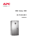
1
w w w. m g e u p s . c o m
Standard Features
◗ Emergency Power Off
button with safety cover.
◗ Interactive Display Panel.
Galaxy 4000
40 – 75KVA
Uninterruptible Power Systems
Installation and User Manual
Installation and User Manual
Galaxy 4000
40 – 75KVA
Uninterruptible Power Systems
Installation and User Manual
Revision History
Galaxy 4000 Installation and User Manual 86-173010-00
Revision: A00 ECN#: 004540 12/2005
Copyright © 2005 MGE UPS SYSTEMS, INC.
All rights reserved. Printed in U.S.A.
MGE UPS SYSTEMS, INC.
1660 Scenic Avenue
Costa Mesa, CA 92626
(714) 557-1636
Customer Care Center: 1-800-438-7373 (Hours: 24/7)
86-173010-00 A00
i
Galaxy 4000
IMPORTANT SAFETY INSTRUCTIONS
SAVE THESE INSTRUCTIONS – This manual contains important instructions for Galaxy
4000 that must be followed during operation and maintenance of the equipment.
WARNING
Opening enclosures expose hazardous voltages. Always refer service to qualified
personnel only.
ATTENTION
L'ouverture des cabinets expose des tensions dangereuses. Assurez-vous
toujours que le service ne soit fait que par des personnes qualifiees.
WARNUNG!
Das öffnen der Gehäuse legen gefährliche Spannungen bloss. Service sollte
immer nur von qualifizierten Personal durchgeführt werden.
WARNING
As standards, specifications, and designs are subject to change, please ask for
confirmation of the information given in this publication.
ATTENTION
Comme les normes, spécifications et produits peuvent changer, veuillez
demander confirmation des informations contenues dans cette publication.
WARNUNG!
Normen, Spezifizierungen und Pläne unterliegen Anderungen. Bitte verlangen Sie
eine Bestätigung über alle Informationen, die in dieser Ausgabe gemacht wurden.
NOTE
This equipment has been tested and found to comply with the limits for a Class
A digital device, pursuant to part 15 of the FCC rules. These limits are designed
to provide reasonable protection against harmful interference when the
equipment is operated in a commercial environment.
This equipment generates, uses, and can radiate radio frequency energy and, if
not installed and used in accordance with the instruction manual, may cause
harmful interference to radio communications. Operation of this equipment in a
residential area is likely to cause harmful interference in which case the user will
be required to correct the interference at user's own expense.
WARNING
To reduce the risk of fire or electric shock, install in a controlled indoor environment free of conductive contaminants.
This equipment is intended only for installations in a RESTRICTED ACCESS
LOCATION.
ATTENTION
Pour réduire le riske d'inccendie ou d'électrocution, installer dans une enciente
intérieure contrôlée en température et humidité et sans contaminants conducteurs.
Ce matériel est destiné seulement pour des installations dans un EMPLACEMENT
RESTREINT D'ACCES.
WARNUNG!
Um die Gefahr von Feuer und elektrischem Schock zu reduzieren, muss das
Gerät in einem temperatur – und feuchtigkeitskontrollierten Raum, frei von
leitungsfähigen Verunreinigungen, installiert werden. Dieses Gerät ist nur für die
Installation an einem Ort mit qeingeschränkter Zugangserlaubnis vorgesehen.
Diese Ausrüstung ist nur für Anlagen in einem EINGESCHRäNKTEN ZUGRIFF
STANDORT bestimmti.
ii
Important Safety Instructions
86-173010-00 A00
Installation and User Manual
WARNING
HIGH LEAKAGE CURRENT. Earth connection essential before connecting
supply.
ATTENTION
COURANT DE FUITE ELEVE. Raccordement a la terre indispensable
avant le raccordement au reseau.
WARNUNG!
Hoher Ableitstrom Vor Inbetriebnahme Schutzleiterverbindung herstellen.
Certification Standards – Three Phase UPS
◗
◗
◗
◗
◗
◗
IEC1004/ANSI C62.41 Standards for Surge Withstand Ability.
FCC Part 15, Subpart J, Class A.
UL/CUL 1778, Standards for Uninterruptible Power Supply Equipment.
NEMA PE 1 - Uninterruptible Power Systems.
NFPA 70 – National Electrical Code.
ISO 9001.
Safety of Persons
◗
◗
◗
The UPS has its own internal power source (the battery). Consequently, the power terminals may be energized
even if the UPS is disconnected from the AC power source.
The UPS must be properly grounded.
The battery supplied with the UPS contains small amounts of toxic materials. To avoid accidents, the directives
listed below must be observed:
- Never burn the battery (risk of explosion).
- Do not attempt to open the battery (the electrolyte is dangerous for the eyes and skin).
- Comply with all applicable regulations for the disposal of the battery.
- Batteries constitute a danger (electrical shock, burns). The short-circuit current may be very high.
- Precautions must be taken for all handling: remove watches, rings, bracelets and any other metal objects,
use tools with insulated handles.
- Do not lay tools or metal parts on top of batteries.
Product Safety
◗
◗
◗
◗
◗
Upstream protection must be installed and be easily accessible.
The UPS can be disconnected from the AC power source by opening the input protective devices.
UPS must be connected to a nearby power source that is easily accessible.
Never block the ventilation openings of the UPS.
The UPS must be installed in a controlled environment.
Special Precautions
◗
◗
◗
The UPS connection instructions and operation described in the manual must be followed in the indicated order.
Check that the indications on the rating nameplate correspond to your AC powered system and to the actual
electrical consumption of all the equipment to be connected to the UPS.
Before and after the installation, if the UPS remains de-energized for a long period, the UPS must be energized
for a period of 24 hours, at least once every 3 months (for a normal storage temperature less than 25°C). This
charges the battery, thus avoiding possible irreversible damage.
Environment
This product has been designed to respect the environment; It does not contain any Chlorofluorocarbon (CFC) or
Hydrochlorofluorocarbon (HCFC).
UPS recycling at the end of service life; MGE UPS SYSTEMS, INC. undertakes to recycle, by certified companies
and in compliance with all applicable regulations, all UPS products recovered at the end of their service life (contact
your MGE UPS SYSTEMS, INC. branch office).
Packing; UPS packing materials must be recycled in compliance with all applicable regulations.
WARNING: This product contains lead-acid batteries. Lead is a dangerous substance for the environment if it is not
properly recycled by specialized companies.
86-173010-00 A00
Certification Standards, Safety of Persons
iii
Galaxy 4000
iv
86-173010-00 A00
Contents
section
description . . . . . . . . . . . . . . . . . . . . . . . . . . . . . . . . . . . . . . . . . . .page
Revision History . . . . . . . . . . . . . . . . . . . . . . . . . . . . . . . . . . . . . . . . . . .i
IMPORTANT SAFETY INSTRUCTIONS . . . . . . . . . . . . . . . . . . . . . . . ii
Certification Standards - Three Phase UPS . . . . . . . . . . . . . . . . . . . . iii
Safety of Persons . . . . . . . . . . . . . . . . . . . . . . . . . . . . . . . . . . . . . . . . iii
Product Safety . . . . . . . . . . . . . . . . . . . . . . . . . . . . . . . . . . . . . . . . . . iii
Special Precautions . . . . . . . . . . . . . . . . . . . . . . . . . . . . . . . . . . . . . . iii
Environment . . . . . . . . . . . . . . . . . . . . . . . . . . . . . . . . . . . . . . . . . . . . .iii
Symbol Usage . . . . . . . . . . . . . . . . . . . . . . . . . . . . . . . . . . . . . . . . . . . V
Section Descriptions . . . . . . . . . . . . . . . . . . . . . . . . . . . . . . . . . . . . . .V
Section 1
Introduction
1.0
1.1
1.2
1.3
1.4
1.5
1.6
1.7
1.8
1.9
1.10
1.11
Section 2
Scope . . . . . . . . . . . . . . . . . . . . . . . . . . . . . . . . . . . . . . . . . . . . . .1 — 1
General Description . . . . . . . . . . . . . . . . . . . . . . . . . . . . . . . . . . .1 — 1
Major Components . . . . . . . . . . . . . . . . . . . . . . . . . . . . . . . . . . . .1 — 2
Single Line Diagram . . . . . . . . . . . . . . . . . . . . . . . . . . . . . . . . . . .1 — 2
Galaxy 4000 Standard Cabinets . . . . . . . . . . . . . . . . . . . . . . . . .1 — 3
Preparation for Operation . . . . . . . . . . . . . . . . . . . . . . . . . . . . . . .1 — 3
Cabinet Placement . . . . . . . . . . . . . . . . . . . . . . . . . . . . . . . . . . . .1 — 3
Heat Rejection and Air Flow . . . . . . . . . . . . . . . . . . . . . . . . . . . . .1 — 3
Cabinet Clearances . . . . . . . . . . . . . . . . . . . . . . . . . . . . . . . . . . .1 — 4
Conduit Plate Locations for Bottom Entry . . . . . . . . . . . . . . . . . .1 — 4
Conduit Plate Locations for Top Entry . . . . . . . . . . . . . . . . . . . . .1 — 5
Preparation for Storage . . . . . . . . . . . . . . . . . . . . . . . . . . . . . . . .1 — 6
Setup and Installation
2.0
2.1
2.2
2.2.1
2.2.2
2.3
2.3.1
2.3.2
2.2.3
2.3.4
2.3.5
2.3.6
2.3.7
2.3.8
2.3.9
86-173010-00 A00
Scope . . . . . . . . . . . . . . . . . . . . . . . . . . . . . . . . . . . . . . . . . . . . . .2 — 1
Installation Steps . . . . . . . . . . . . . . . . . . . . . . . . . . . . . . . . . . . . .2 — 1
Environmental and Electrical Specifications . . . . . . . . . . . . . . . . .2 — 1
Environmental Recommendations . . . . . . . . . . . . . . . . . . . . . . . .2 — 1
Electrical Specifications . . . . . . . . . . . . . . . . . . . . . . . . . . . . . . . .2 — 2
Electrical Connections . . . . . . . . . . . . . . . . . . . . . . . . . . . . . . . . .2 — 2
UPS Connections . . . . . . . . . . . . . . . . . . . . . . . . . . . . . . . . . . . . .2 — 3
Main AC Input Connections . . . . . . . . . . . . . . . . . . . . . . . . . . . . .2 — 3
Bypass AC Input Connections (optional) . . . . . . . . . . . . . . . . . . .2 — 3
AC Output Connections . . . . . . . . . . . . . . . . . . . . . . . . . . . . . . . .2 — 3
Battery Connections . . . . . . . . . . . . . . . . . . . . . . . . . . . . . . . . . . .2 — 4
Remote Emergency Power Off Connections . . . . . . . . . . . . . . . .2 — 4
Battery Control Connections . . . . . . . . . . . . . . . . . . . . . . . . . . . .2 — 4
External Maintenance Bypass Control Connections (optional) . .2 — 5
Accessories Outlets . . . . . . . . . . . . . . . . . . . . . . . . . . . . . . . . . . .2 — 5
Contents
I
Galaxy 4000
Section 2
Setup and Installation
section
description
2.4
Relay Communication Card Contacts . . . . . . . . . . . . . . . . . . . . .2
Relay Communication Card Connections . . . . . . . . . . . . . . . . . .2
Characteristics of the Output Contacts . . . . . . . . . . . . . . . . . . . .2
Characteristics of the Input Contacts . . . . . . . . . . . . . . . . . . . . . .2
2.4.1
2.4.2
2.4.3
Section 3
3.1.1
3.1.2
3.1.3
3.2
3.3
3.4
3.4.1
3.4.2
3.4.3
3.4.4
3.4.5
3.4.6
3.5
3.6
3.7
3.8
3.9
4.1.1
4.2
4.3
4.4
4.5
4.6
5
6
7
7
Scope . . . . . . . . . . . . . . . . . . . . . . . . . . . . . . . . . . . . . . . . . . . . . .3 — 1
Operator Interface Keys and Indicators . . . . . . . . . . . . . . . . . . . .3 — 1
LED Indicator Functions . . . . . . . . . . . . . . . . . . . . . . . . . . . . . . . .3 — 2
Screen Saver . . . . . . . . . . . . . . . . . . . . . . . . . . . . . . . . . . . . . . . .3 — 2
Operational Summary Screen . . . . . . . . . . . . . . . . . . . . . . . . . . .3 — 2
Display Menu Structure . . . . . . . . . . . . . . . . . . . . . . . . . . . . . . . .3 — 3
Main Menu Screen . . . . . . . . . . . . . . . . . . . . . . . . . . . . . . . . . . . .3 — 4
Measurements . . . . . . . . . . . . . . . . . . . . . . . . . . . . . . . . . . . . . . .3 — 4
Battery Measurements Screen . . . . . . . . . . . . . . . . . . . . . . . . . . .3 — 4
Power Measurements Screen . . . . . . . . . . . . . . . . . . . . . . . . . . .3 — 5
Current Measurements Screen . . . . . . . . . . . . . . . . . . . . . . . . . .3 — 5
Voltage Measurements Screen . . . . . . . . . . . . . . . . . . . . . . . . . .3 — 6
Frequency Measurements Screen . . . . . . . . . . . . . . . . . . . . . . . .3 — 6
Ratios Screen . . . . . . . . . . . . . . . . . . . . . . . . . . . . . . . . . . . . . . . .3 — 6
Mimic Diagrams . . . . . . . . . . . . . . . . . . . . . . . . . . . . . . . . . . . . . .3 — 7
Status Screen . . . . . . . . . . . . . . . . . . . . . . . . . . . . . . . . . . . . . . . .3 — 7
Settings Screen . . . . . . . . . . . . . . . . . . . . . . . . . . . . . . . . . . . . . .3 — 8
Commands Screen . . . . . . . . . . . . . . . . . . . . . . . . . . . . . . . . . . . .3 — 9
Startup Procedure Screen . . . . . . . . . . . . . . . . . . . . . . . . . . . . . .3 — 9
Scope . . . . . . . . . . . . . . . . . . . . . . . . . . . . . . . . . . . . . . . . . . . . . .4 — 1
Preparing for Startup . . . . . . . . . . . . . . . . . . . . . . . . . . . . . . . . . .4 — 1
Pre-Startup Safety Check List . . . . . . . . . . . . . . . . . . . . . . . . . . .4 — 1
Normal Startup Procedure . . . . . . . . . . . . . . . . . . . . . . . . . . . . . .4 — 3
Post Startup Safety Check List . . . . . . . . . . . . . . . . . . . . . . . . . .4 — 4
Shutdown Procedure . . . . . . . . . . . . . . . . . . . . . . . . . . . . . . . . . .4 — 4
Shutdown Using EPO . . . . . . . . . . . . . . . . . . . . . . . . . . . . . . . . . .4 — 4
Recovery from EPO . . . . . . . . . . . . . . . . . . . . . . . . . . . . . . . . . . .4 — 4
Maintenance
5.0
5.1
II
—
—
—
—
Operation
4.0
4.1
Section 5
page
Display Panel
3.0
3.1
Section 4
(continued)
Scope . . . . . . . . . . . . . . . . . . . . . . . . . . . . . . . . . . . . . . . . . . . . . .5 — 1
Servicing Batteries . . . . . . . . . . . . . . . . . . . . . . . . . . . . . . . . . . . .5 — 1
Contents
86-173010-00 A00
Installation and User Manual
Section 6
Warranty, Registration & Customer Support
description
page
MGE Warranty & Proprietary Rights for Three Phase Products . . . . . . . . . . . . . .6 – 1
MGE Standard Three Phase Warranty
Proprietary Rights Statement
Warranty and Product Registration . . . . . . . . . . . . . . . . . . . . . . . . . . . . . . . . . . . .6 – 2
User Information
Product information
Warranty Extension (Warranty+)
MGE Customer Care Center . . . . . . . . . . . . . . . . . . . . . . . . . . . . . . . . . . . . . . . .6 – 3
Technical Support and Product Services
Who To Contact
Scheduling Field Service Engineer Support
Return Policy for Repair of Three Phase Products (RGA)
Caution: Record All Serial Numbers! . . . . . . . . . . . . . . . . . . . . . . . . . . . . . . . . . .6 – 4
Glossary
Reorder Form
86-173010-00 A00
Contents
III
Galaxy 4000
Figures
figure description
page
1-1
1-2
1-3
1-4
1-5
Galaxy 4000 UPS System . . . . . . . . . . . . . . . . . . . . . . . . . . . . . . . . . . . .1 — 1
Galaxy 4000 UPS System - Single Line Diagram . . . . . . . . . . . . . . . . . .1 — 2
Cabinet Placement, Airflow and Recommended Clearances . . . . . . . . .1 — 4
Configuration for Bottom Entry . . . . . . . . . . . . . . . . . . . . . . . . . . . . . . . . .1 — 5
Configuration for Top Entry . . . . . . . . . . . . . . . . . . . . . . . . . . . . . . . . . . . .1 — 5
2-1
2-3
Typical Power Connections . . . . . . . . . . . . . . . . . . . . . . . . . . . . . . . . . . .2 — 4
Relay Communication Card . . . . . . . . . . . . . . . . . . . . . . . . . . . . . . . . . . .2 — 6
3-1
3-2
3-3
3-4
3-5
3-6
3-7
3-8
3-9
3-10
3-11
3-12
3-13
3-14
3-15
Display Panel Keys and Indicators . . . . . . . . . . . . . . . . . . . . . . . . . . . . . .3 — 1
Screen Saver . . . . . . . . . . . . . . . . . . . . . . . . . . . . . . . . . . . . . . . . . . . . . .3 — 2
Operational Summary screen . . . . . . . . . . . . . . . . . . . . . . . . . . . . . . . . . .3 — 2
UPS Display Menu Structure . . . . . . . . . . . . . . . . . . . . . . . . . . . . . . . . . .3 — 3
Main Menu screen . . . . . . . . . . . . . . . . . . . . . . . . . . . . . . . . . . . . . . . . . .3 — 4
Battery Measurements screen . . . . . . . . . . . . . . . . . . . . . . . . . . . . . . . . .3 — 4
Power Measurements screen . . . . . . . . . . . . . . . . . . . . . . . . . . . . . . . . . .3 — 5
Current Measurements screen . . . . . . . . . . . . . . . . . . . . . . . . . . . . . . . . .3 — 5
Voltage Measurements screen . . . . . . . . . . . . . . . . . . . . . . . . . . . . . . . . .3 — 6
Frequency Measurements screen . . . . . . . . . . . . . . . . . . . . . . . . . . . . . .3 — 6
Ratios screen . . . . . . . . . . . . . . . . . . . . . . . . . . . . . . . . . . . . . . . . . . . . . .3 — 6
Mimic Diagrams screen . . . . . . . . . . . . . . . . . . . . . . . . . . . . . . . . . . . . . .3 — 7
Status screen . . . . . . . . . . . . . . . . . . . . . . . . . . . . . . . . . . . . . . . . . . . . . .3 — 7
Settings screens . . . . . . . . . . . . . . . . . . . . . . . . . . . . . . . . . . . . . . . . . . . .3 — 8
Commands screens . . . . . . . . . . . . . . . . . . . . . . . . . . . . . . . . . . . . . . . . .3 — 9
4-1
Galaxy 4000 Device Locations . . . . . . . . . . . . . . . . . . . . . . . . . . . . . . . . .4 — 2
Tables
table description
IV
page
1-1
Heat Rejection Data . . . . . . . . . . . . . . . . . . . . . . . . . . . . . . . . . . . . . . . . .1 — 4
2-1
2-2
Electrical Specifications for the Galaxy 4000 . . . . . . . . . . . . . . . . . . . . . .2 — 2
Relay Contacts (communication card) . . . . . . . . . . . . . . . . . . . . . . . . . . .2 — 5
3-1
Three LED Indicators . . . . . . . . . . . . . . . . . . . . . . . . . . . . . . . . . . . . . . . .3 — 2
Contents
86-173010-00 A00
Installation and User Manual
Symbol Usage
This manual uses five icon symbols with text to convey important information and tips.
WARNING
Indicates information provided to protect the user and service personnel against
safety hazards and/or possible equipment damage.
CAUTION
Indicates information provided to protect the user and service personnel against
possible equipment damage.
ELECTRICAL
Indicates information provided to protect the user and service personnel against
possible electrical hazard and equipment damage.
IMPORTANT
Indicates information provided as an operating instruction, or as an operating tip.
NOTE
Indicates information provided as an operating tip or an equipment feature.
Section Descriptions
1
Introduction
Provides a general description of the Galaxy 4000 systems intended use, major components, mechanical and
environmental specifications.
2
Setup and Installation
Guides the user through tools and equipment required for unpacking and performing connections required for initial
installation. Included are the electrical specifications, environmental recommendations and connection details.
3
Display Panel
Describes the operator interface screens, keys, and mimic diagram.
4
Operation
Provides startup, shutdown, and normal operation of the Galaxy 4000 UPS. Included are pre and post startup safety
checklists.
5
Maintenance
Describes maintenance and safety information on servicing batteries for the Galaxy 4000.
A Glossary provides definitions of abbreviations and terms used in this manual.
86-173010-00 A00
Symbol Usage and Section Descriptions
V
Galaxy 4000
VI
86-173010-00 A00
Introduction
1.0
Scope
Provides a general description of the Galaxy 4000 systems intended use, major components, mechanical and
environmental specifications.
1.1
General Description
The Galaxy 4000 is the world’s first data center grade Uninterruptible Power Supply system designed specifically
for mid-range enterprise level applications. The Galaxy 4000 family consists of units available in power ratings from
40 - 75KVA, and are optimized for compatibility with nonlinear computer-type loads.
By incorporating the Ultra High Availability Topology (UHAT), the Galaxy 4000 family of UPS systems are designed
to provide the optimal level of reliability and to react to any power disturbance in an inherently safe way to protect
the critical load. The Galaxy 4000 all-in-one design incorporates every feature into one compact cabinet, including
a graphical user interface, power factor corrected input, and communication cards that support network based
power management.
The Galaxy 4000 UPS and its auxiliary equipment are designed for installation in a room where humidity and
temperature can be controlled.
The Galaxy 4000 UPS and auxiliary equipment is listed for safety by Underwriters Laboratories, Inc. (UL) under UL
Standard 1778 – Uninterruptible Power Systems; and also listed by Underwriters Laboratories (CUL) under Canadian
Standards Association (CSA) standard C22.107.
Figure 1-1: Galaxy 4000 UPS System.
86-173010-00 A00
Introduction
1—1
Galaxy 4000
1.2
1.3
Major Components
Rectifier
Converts AC input voltage to DC voltage. The rectifier uses IGBT (Insulated G a t e
Bipolar Transistor) power transistors and a Pulse Width Modulated (PWM)
technique to provide input power factor correction and to minimize any harmonic
reflected onto the input power lines.
Inverter
Converts DC voltage from the rectifier or from the batteries into AC output voltage
to maintain the attached load. This module uses the IGBT technology to provide
digital power quality.
Static Switch
Automatically supplies the attached load from the bypass source when the inverter
is off.
Battery System
Stores energy for utilization by the inverter and attached load in the event that utility
AC power is lost or is of unacceptable quality.
Single Line Diagram
During normal operation, the utility power (Main input) is supplied to the UPS rectifier. The rectifier converts the AC
power to DC that is supplied to the inverter. The inverter converts the DC voltage to three-phase regulated AC
voltage, which is supplied to the attached load.
During power failure conditions, the inverter is supplied by the stored energy in the battery system, and the load is
powered continuously with no interruption.
The Galaxy 4000 UPS is designed for internal operation of 208VAC input and output. External batteries, and an
output distribution panel may be contained in auxiliary cabinets similar in design to the Galaxy 4000 cabinet.
Batteries or external maintenance bypass circuit breakers may also be contained in third party cabinets or wall
mounted units.
Figure 1-2: Galaxy 4000 UPS System – Single Line Diagram.
KA
Q3BP (OPTIONAL)
OPTIONAL
BYPASS
INPUT
208YVAC
MAIN
INPUT
208YVAC
A
B
C
A
B
C
BYPASS
INPUT
TB3
MAIN
INPUT
TB1
BYPASS
STATIC
SWITCH
Q4S
Q1
INPUT
STATIC
INPUT
SWITCH
FUSES
PFC
BOOST
RECTIFIER
OUTPUT
STATIC
INVERTER SWITCH
OUTPUT A
TB2 B
C
OUTPUT
CB
42 POLE
PANELBOARD
Q5N
KB
(OPTIONAL)
(OPTIONAL)
TO
CRITICAL
LOAD
BATTERY
STATIC SWITCH
N
G
N
G
BATTERY
CHARGER
UPS
TB4
7 8 9 10
SUPPLIED BY MGE &
CON NECTED BY CUSTOMER
(ADJACENT VERSION)
SUPPLIED & CONNECTED
BY CUSTOMER
(STAND ALONE VERSION)
CONTROL CONNECTIONS
(SEE UPS INSTALLATION DWG)
TB4
REPO ON MBS
CB1
CB1
CB1
DISTRIBUTION
SUPPLIED BY MGE &
CONNECTED BY CUSTOMER
CB1
BATTERY
1—2
Introduction
86-173010-00 A00
Installation and User Manual
1.4
Galaxy 4000 Standard Cabinets
The Galaxy 4000 individual cabinet dimensions are:
◗
UPS cabinet: 72.1in (1831mm) H x 33.5in (851mm) W x 35.6in (904mm) D.
◗
External battery cabinet: 72.1in (1831mm) H x 26.5in (673mm) W x 33.5in (851mm) D OR –
◗
External battery cabinet: 72.1in (1831mm) H x 33.5in (851mm) W x 33.5in (851mm) D.
◗
Distribution cabinet: 72.1in (1831mm) H x 19.5in (495mm) W x 33.5in (851mm) D.
The UPS cabinet is designed to provide for top and bottom entry of the utility power feed. An output voltage of
208VAC is standard with the Galaxy 4000 and does not require any additional cabinetry. The complete list of
additional cabinets that could be included with your Galaxy 4000 system are: external maintenance bypass wall
cabinet, external battery cabinet, and distribution cabinet.
The external battery cabinets are provided in two different cabinet sizes depending upon the battery type selected.
Up to four battery cabinets may be provided. The cabinets may be installed adjacent to the UPS or remotely and
are designed for top and bottom entry. The distribution cabinet provides a 42 pole panelboard, with an optional
submain circuit breaker. The cabinet is designed for top and bottom entry.
1.5
Preparation for Operation
Several items must be considered when preparing the Galaxy 4000 UPS system for operation.
First
The UPS cabinet and its auxiliary cabinets must be arranged in the required configuration to insure that
the interconnection cables are located in the correct adjacent cabinets.
Second The cabinets must be in a location that provides for proper air flow and heat rejection.
Third
The room in which the Galaxy 4000 UPS system is located must maintain environmental conditions within
recommended tolerances.
Forth
All electrical connections must utilize the top or bottom conduit entries provided.
The following sections discuss these items in more detail.
1.6
Cabinet Placement
The complete UPS system may consist of one to three cabinets depending on the options selected. The UPS
cabinet allows system options to be selected based on the application. When facing the Galaxy 4000 UPS from the
front, the standard arrangement provides for any external batteries to be located on the right hand side, and the
distribution cabinet to be located on the left hand side of the UPS. Refer to Figure 1-3 for cabinet placement.
1.7
Heat Rejection and Air Flow
The Galaxy 4000 UPS cabinets generate heat and exhaust air through the top portion of its enclosures. Air intake
is through the bottom and front of the cabinet. All other cabinets are convection cooled. To assist you in planning for
your HVAC needs, heat rejection data is provided in Table 1-1. The cabinet airflow and recommended top clearance
are provided in Figure 1-3. The Galaxy 4000 is intended for use in an environment where control of temperature
and humidity is provided.
86-173010-00 A00
Introduction
1—3
Galaxy 4000
Figure 1-3: Cabinet Placement, Airflow and Recommended Clearances.
DISPLAY PANEL
ALLOW 36" TOP CLEARANCE
FOR FAN EXHAUST AND SERVICE MAINTENANCE
AIR EXHAUST
?
(1
!
2
3
4
(
!
AIR INTAKE
LEVELING
JACKS
DISTRIBUTION
CABINET
UPS CABINET
Galaxy 4000
EXTERNAL BATTERY
CABINET (Optional)
CASTERS
(Optional)
FRONT VIEW
Table 1-1: Heat Rejection Data.
Heat Rejection Data @ 208/208VAC
UPS cabinet
40KVA
50KVA
65KVA
75KVA
BTU/Hr
14,900
18,700
24,200
28,000
NOTE:
1.8
To provide for adequate ventilation, a minimum of 36 inches clearance should
be maintained above the top of the Galaxy 4000 cabinet.
Cabinet Clearances
The Galaxy 4000 UPS cabinet top clearance of 36 inches for fan exhaust is recommended. Additionally, adequate
space must be included in the front and top of each cabinet (approx. 36 inches) to allow the doors/panels of the
cabinet to be opened for service and maintenance procedures.
For an installation where seismic requirements must be met, additional clearance at the side of the cabinet must be
included to accommodate the seismic anchors. Contact your local MGE Sales Representative to order. See Figure 1-4.
1.9
Conduit Plate Locations for Bottom Entry
Cable entry through the bottom is the standard preferred design for the Galaxy 4000 UPS cabinet. The bottom entry
conduit plate provides space for up to five (5) separate conduit entries. The plate is secured with screws which
should be retained for the conduit plate after the power connections are made. See Figure 1-4 for the location of
the bottom entry conduit plates.
1—4
Introduction
86-173010-00 A00
Installation and User Manual
Figure 1-4: Configuration for Bottom Entry.
AIR INTAKE
DO NOT BLOCK
2.4
18.0
25.0
(32.0)
28.8
3.2
9.6
15.7
14.0
SEISMIC BRACKET (optional)
(4 PLCS)
2.9
38.1
CABLE ENTRY PLATE
46.6
(53.6)
1.10
Conduit Plate Locations for Top Entry
The UPS cabinet for the Galaxy 4000 is capable of accepting power input and output cables through a top entry.
The conduit plate on the top of the cabinet provides provisions for knockouts for conduit and is secured to the
cabinet with screws. See Figure 1-5.
Figure 1-5: Configuration for Top Entry.
76.5
(83.5)
18.8
25.0
(32.0)
9 x 20.5
CONDUIT
32.0
10 x 20.5
CONDUIT
16.7
16.5
33.5
8.9
AIR EXHAUST
DO NOT BLOCK
(16) x 1.125 K.O.
(34) .857 K.O.
DISTRIBUITION
26W BATTERY
(33W BATTERY)
UPS
86-173010-00 A00
Introduction
1—5
Galaxy 4000
1.11
Preparation for Storage
If the equipment is to be stored prior to installation, it should be stored in a cool, dry, well-ventilated location that is
protected against rain, splashing water, chemical agents, etc. The equipment should be covered with a tarpaulin or
plastic wrapper to protect it against dust, dirt, paint, or other foreign materials. See the section of this manual titled
"Environmental Recommendations" for recommended storage environmental conditions.
NOTE
1—6
Batteries should be stored no longer than three (3) months at 25°C (77°F) or lower
prior to recharging. Exceeding the recommended ambient storage temperature
will reduce battery back-up time and may adversely affect battery life.
Introduction
86-173010-00 A00
Setup and Installation
2.0
Scope
Guides the user through tools and equipment required for unpacking and performing connections required for initial
installation. Included are the electrical specifications, environmental recommendations and connection details.
2.1
Installation Steps
MGE recommends correct installation verification and unit startup to be performed by a qualified MGE Field
Service Engineer.
CAUTION
Scheduling of the MGE Field Service Engineers typically should be done 7 to 10
days before they are required on-site. If the startup of the UPS is critical to
maintaining your schedule, please call the MGE toll free telephone number at
1-800-438-7373 for assistance.
To insure a successful installation, each of these (5) steps should be followed in their correct sequence.
Note that any unauthorized installation may cause damage to the UPS(s).
First steps by an on-site qualified Technical Engineer
Step 1. Unpack and position the unit.
Step 2. Connect the main (utility) power.
Step 3. Connect the output to the load.
Final steps by MGE Field Service Engineer
Step 4. Call MGE and wait for the MGE Field Service Engineer to approve the installation.
Step 5. The MGE Field Service Engineer finalizes installation and the startup process.
2.2
Environmental and Electrical Specifications
2.2.1
Environmental Recommendations
Recommended environment 20° to 25°C (68° to 77°F.); 50% relative humidity; computer room or other
temperature, and humidity-controlled environment.
Operating temperature
0° to 30°C (32° to 86°F) except battery.
Storage
-20° to 40°C (-4° to 113°F) except battery.
Humidity
up to 90% non-condensing (operating).
Altitude
sea level to 3,000 feet without derating.
Acoustic noise
69 dBA at rated load as measured 5 feet from the front of the UPS cabinet.
86-173010-00 A00
Installation
2—1
Galaxy 4000
2.2.2
Electrical Specifications
Table 2-1: Electrical Specifications for the Galaxy 4000.
Output Power Rating (0.8) PF
40KVA
50KVA
65KVA
75KVA
UPS Voltage (input/output)
208/208
208/208
208/208
208/208
Input/Output Requirements & Frequency
Three phase, Three wire + N + G, 60Hz
Input Phase Rotation
A,B,C Clockwise
Input Power Factor
>.98
Input Current
102A
127A
166A
191A
Maximum Input Current(at low line -15%)
120A
150A
195A
225A
Bypass Current
111A
139A
180A
208A
Output Current
111A
139A
180A
208A
Battery Voltage
198 VDC End Voltage 240VDC Nominal 282VDC Max. Maintenance Voltage
Max. Battery Current at Nominal Battery Voltage (240 VDC at 100% Load)
157A
Max. Battery Current at Nominal End- Voltage (198 VDC at 100% Load)
190A
196A
255A
238A
309A
294A
357A
Battery Disconnect Circuit Breaker Rating
250A
400A
Input, Bypass, and Maintenance Bypass (optional) Switch Rating
150A
250A
Input Fuse Rating
200A
300A
Output Isolation Circuit Breaker Rating
175A
300A
NOTE: Interrupted Transfer to Bypass Source:
If the bypass source is beyond the conditions stated below, the UPS will make an interrupted transfer (not more than 100 msec. in duration).
1. Bypass voltage greater than +15%, -15% from the UPS rated output voltage.
2. Bypass frequency greater than ±2 Hz from the UPS rated output frequency.
2.3
Electrical Connections
CAUTION
Only an authorized electrical professional should access electrical connections.
A severe shock hazard exists.
The ONLY user serviceable items in the Galaxy 4000 unit are:
A.
The main and bypass power connections.
B.
The load connection.
C.
Any cable connection to external or auxiliary modules.
D.
The communication card options.
The access method for connections made to the communication cards is clearly seen when the front right door to
the Galaxy 4000 unit is opened. However, access to the main, bypass and load connections is made through the
removal of the safety panel located in the lower right of the Galaxy 4000 (with the right door open). This safety panel
is removed by first removing the screws securing the panel. It can then be removed by lifting the safety panel away
from the unit.
CAUTION
2—2
Before making any electrical connections, verify that all battery disconnect circuit
breakers (CB1) are in the "off" position. Customer-supplied upstream protective
devices and distribution circuits should be OFF.
Installation
86-173010-00 A00
Installation and User Manual
2.3.1
UPS Connections
Electrical connections and cabinet interconnection will vary depending upon the configuration and options selected
with your Galaxy 4000 UPS system. Refer to the installation drawings supplied with your equipment.
Connecting Power Cable Connections:
To access the connection terminal blocks, open the right door to the Galaxy 4000 UPS. Remove the safety panel
located in the lower right hand section of the unit. See Figure 2-1.
a.
The ground and neutral conductors must be connected to the ground and neutral busbars, respectively. The
input and output neutral are connected at the neutral busbar.
b.
Connect the three conductors of the main AC source to terminal block TB1.
c.
If bypass source is present, connect the conductors of the bypass AC source to terminal block TB3.
If bypass source is not present, verify jumpers in place between TB1 and TB3.
d.
Connect the three conductors supplying the load to terminal block TB2.
e.
Connect the battery conductors to the positive and negative busbars.
f.
Secure all cables with cable ties.
g.
Put all panels and covers back in place.
2.3.2
Main AC Input Connections
The connections to be made are the three phases, neutral, and ground cables from the utility AC power source to
the UPS. The main AC input cables are terminated at the main input terminal block (TB1). See Figure 2-1.
IMPORTANT
2.3.3
For single input (optional configuration), jumper cables are provided from terminal
blocks TB1 to TB3.
Bypass AC Input Connections (optional)
The bypass AC input cables are terminated at the bypass input terminal block (TB3). This option provides a separate
AC input source for bypass operation. See Figure 2-1.
2.3.4
AC Output Connections
The connections to be made are the three phases, neutral, and ground cables from the load to the UPS. The output
cables are terminated at the output terminal block (TB2). See Figure 2-1.
86-173010-00 A00
Installation
2—3
Galaxy 4000
Figure 2-1: Typical Power Connections.
FRONT VIEW
TB4 Control
A
B
REAR AREA
Output
TB2
C
C
A
B
B
C
A
TB3 Bypass
Input
TB1 Main
Input
TB4
Ground
FRONT
Neutral
TB1
Battery Positive
TB2
Battery Negative
GROUND
BUSBARS
NEUTRAL
NEGATIVE
POSITIVE
BUSBARS
2.3.5
Battery Connections
The connections to be made are the positive, negative, and ground cables from the battery cabinet to the UPS. The
battery cables are terminated at the positive, negative, and ground busbars. See Figure 2-1.
2.3.6
Remote Emergency Power Off Connections
The control connections are available for Remote Emergency Power Off (REPO) through a customer-supplied
(normally closed) pushbutton. With REPO connected, the jumper on the REPO terminal blocks must be removed.
See Figure 2-1.
1.
Remove the jumper from terminal block TB4 located across terminals 7 and 8.
2.
Connect the remote emergency power off NC contact to terminals 7 and 8.
IMPORTANT
2.3.7
The UPS is also equipped with a local Emergency Power Off (EPO) button on the
front of the UPS cabinet. This switches all UPS critical power off. EPO or REPO
should be used for emergency only!
Battery Control Connections
The battery control connections are made with the battery control cables from the external battery cabinet to the
UPS terminal block TB4-1 to TB4-4. See Figure 2-1.
2—4
Installation
86-173010-00 A00
Installation and User Manual
2.3.8
External Maintenance Bypass Control Connections (optional)
The external maintenance bypass (MBP) control connections are made with the MBP control cable from the external
MBP to the UPS terminal block TB4-9 to TB4-10. See Figure 2-1.
ELECTRICAL
2.3.9
These wires carry HIGH VOLTAGE 120VAC.
Accessories Outlets
The 120VAC outlets to be used on MGE authorized accessories only. The outlets total current not to exceed 2 amps.
CAUTION
2.4
Improper use of outlets may cause failure or damage to UPS.
Relay Communication Card Contacts
The relay communication card contains six programmable dry contact outputs and two programmable dry inputs
and is standard on the Galaxy 4000. The inputs and outputs are factory programmed according to functions listed
in Table 2-2.
Table 2-2: Relay Contacts (communication card).
INPUTS
Factory Settings
Options (available on both contacts)
1.A
UPS ON
1.B
UPS OFF
-Room temperature fault.
-Transfer to bypass disabled.
-Transfer to bypass disabled if bypass AC source out of tolerance.
-Desynchronize UPS from bypass AC source.
OUTPUTS
Factory Settings
Options (available on all contacts)
1.1
General alarm
1.2
Battery fault
1.3
Load on UPS
1.4
Load on automatic bypass
1.5
Load on battery power
1.6
Low battery warning
-Overload.
-PFC Fault.
-Inverter fault.
-Charger fault.
-Automatic bypass fault.
-Bypass AC source out of tolerance.
-Battery-temperature fault.
-Emergency power off activated.
-Battery circuit breaker(s) open.
-Phase-sequence fault on normal or bypass.
-AC source.
-Blown fuse(s).
-Transfer to bypass AC source disabled.
-Operation in ECO mode.
-UPS on bypass AC source.
The output contacts numbers for a second relay board installed will be 2.1 to 2.6. Contacts are of the NO
(normally open) type. For dry contacts setting see section 3.7
86-173010-00 A00
Installation
2—5
Galaxy 4000
CAUTION
2.4.1
Isolate and lock-out all power sources for this card before making connections.
Never connect ELSV (extra low safety voltage) and non-ELSV circuits to the
different outputs of the same card.
Relay Communication Card Connections
Refer to Figure 2-3 for relay communication card, cover and hardware details. See Figure 4-1 for communication
card port location in the unit.
1.
Remove the cover “3” secured by the screws “1”.
2.
Run the communication cables through the cable entry holes “4”.
3.
Connect the conductors to the input “6” and output “5” terminal blocks (refer to Figure 2-3 for a
connection example.)
4.
Put the cover back in place and secure it with the screws “1”.
5.
Tighten the screws “7” to clamp the cables.
6.
Indicate the locations of the power sources on the labels.
7.
Insert the card in its slot.
8.
Secure the card with two screws “2”.
Figure 2-3: Relay Communication Card.
Revmove Cover
1
2
3
2
4
6
1
BA
2
3 4
5
1
6
5
6
2
3
4
5
6
5
4
BA
3
7
Replace Cover
1
2
2
7
2—6
Installation
86-173010-00 A00
Installation and User Manual
2.4.2
Characteristics of the Output Contacts
Relay Type
Normally Open.
Max. voltage
250VAC, 30VDC.
Max. current
2 A.
Cable
4 x 0.93 mm, 6.6 ±0.3 mm.
2.4.3
Characteristics of the Input Contacts
Switched voltage
5VDC.
Consumption
10 mA.
Cable
4 x 0.34 mm, 5 ±0.5 mm.
Output alarms are always activated on the conditions stated unless requested by customer to operate on
other conditions.
Input contacts are designed for remote UPS operation. Use extreme caution when using these contacts so as not
to endanger persons or compromise the UPS load.
86-173010-00 A00
Installation
2—7
Galaxy 4000
(This page left blank intentionally)
2—8
86-173010-00 A00
Display Panel
3.0
Scope
Describes the operator display panel, interface screens, keys, and mimic diagram.
3.1
Operator Interface Keys and Indicators
The operator interface screens contained on the Galaxy 4000 display panel provide an easy to use method to
access and control the Galaxy 4000 features.
The Soft Keys are programmed to allow you to scroll up and down through the list of alarms (soft keys #1 and #2).
Soft key #3 allows you to delete a specific alarm message. Soft key #4 allows you to examine in further detail a
specific alarm message. Although slightly different in operation, the detail key (soft key #4) must be held down to
examine the message details. See Figure 3-1.
The four dedicated purpose keys are the main menu, online help, ON (green), and OFF (gray) buttons. For inverter
OFF a confirmation will always be requested.
Figure 3-1: Display Panel Keys and Indicators.
Galaxy 4000
COLOR DISPLAY
(Screen Saver shown)
?
(
MAIN MENU KEY
!
1
2
3
4
(
ONLINE HELP KEY
!
INVERTER OFF BUTTON
LOAD PROTECTED (green) LED INDICATOR
MINOR FAULT (orange) LED INDICATOR
MAJOR FAULT (red) LED INDICATOR
86-173010-00 A00
SOFT KEYS
1 = Scroll up
2 = Scroll down
3 = View Alarm messages
4 = Detail of Alarm message
INVERTER ON BUTTON
Display Panel
3—1
Galaxy 4000
3.1.1
LED Indicator Functions
The three LED indicators (see Figure 3-1) provide the following information as shown in Table 3-1:
Table 3-1: Three LED Indicators.
Green LED
Orange LED
ON
Load on UPS
Flashing
Load is on battery power
OFF
Inverter not connected to load
Red LED
Minor fault such as:
ON
Major fault such as:
ON
Loss of AC input power
Internal fault
Battery problem
Rectifier fault
Overload
Inverter fault
Bypass static switch fault
Load on bypass
Battery not connected
IMPORTANT
3.1.2
When the Red LED is ON, the load is not protected.
Figure 3-2: Screen Saver.
Screen Saver
When the Galaxy 4000 system has been in continuous
operation, the operator interface will present a screen saver
display. See Figure 3-2.
Galaxy 4000
The product name, "Galaxy 4000", will be moving around
the screen to provide an indication that the unit is
functional.
Galaxy 4000
Galaxy 4000
3.1.3
Operational Summary Screen
Figure 3-3: Operational Summary screen.
Pressing any of the keys will cause the unit to provide an
operational summary display with the following information.
This display will quickly show the operator the time/date, the
KVA load on all three phases, as well as the battery level.
See Figure 3-3.
NORM Load Protected
03/30/2004
09:30
KVA
0.6
0.6 0.6
Battery
volt
3—2
Display Panel
86-173010-00 A00
Installation and User Manual
3.2
Display Menu Structure
This display menu structure is provided below for the Galaxy 4000 system in Figure 3-4.
Figure 3-4: UPS Display Menu Structure.
UPS MAIN MENU
UPS
MAIN MENU
MEASUREMENTS
MIMIC DIAGRAMS
STATUS
SETTINGS
COMMANDS
STARTUP PROCEDURE
MEASUREMENTS
MEASUREMENTS
BATTERY
MEASUREMENTS
POWER
MEASUREMENTS
CURRENT
MEASUREMENTS
MIMIC DIAGRAMS
VOLTAGE
MEASUREMENTS
FREQUENCY
MEASUREMENTS
RATIOS
STATUS
STATUS
MIMIC DIAGRAMS
MIMIC
STATUS AND
ALARMS
EVENT LOG
STATISTICS
HISTORY
SETTINGS
SETTINGS
LANGUAGE
DATE/TIME
CONTRAST
BUZZER
PERSONALIZATION
OUTPUT VOLTAGE
DRY CONTACTS
PASSWORD
COMMANDS
COMMANDS
FAULT RESET
BATTERY
EQUALIZATION
FORCED TRANSFER
TO UPS
FORCED TRANSFER
TO BYPASS
DESYNCHRONIZE
AC BYPASS
STARTUP PROCEDURE
STARTUP
PROCEDURE
STARTUP
86-173010-00 A00
UPS SHUTDOWN
TRANSFER TO
MANUAL BYPASS
Display Panel
3—3
Galaxy 4000
3.3
Figure 3-5: Main Menu screen.
Main Menu Screen
The Main Menu screen allows the operator to access many
displays to monitor the operating performance of Galaxy
4000, obtain alarm information, change operational settings
as well as issue software based commands.
Main Menu
vo lt
Measurements
Mimic Diagrams
The Main Menu conveniently displays groups of items
according to function. By using one of the first two soft keys
the selection cursor may be moved up and down until the
desired display group is selected. Then by pressing the
fourth soft key, the selected display (or display group) will
be summoned. See Figure 3-5.
3.4
O IO IO
IO IO I I
O IO IO
Status
Settings
Commands
Measurements
Selecting the Measurements option from the main menu
provides the following screen selections: battery, power,
current, voltage, frequency measurements, and ratios.
3.4.1
Battery Measurements Screen
Figure 3-6: Battery Measurements screen.
The Battery Measurements screen provides a rapid
assessment of the available battery voltage, current,
battery charge, temperature as well as expected service
life. See Figure 3-6.
Battery measurements
Voltage
257 V
Current
0.0 A
The backup time measurement will be calculated if the
following battery parameter identification (BPI) requirements are met:
Backup Time
not avail.
Battery Charge
100%
Temperature
21* c
Required Conditions to Initiate BPI:
Service Life
60 Mth
◗
BPI set to automatic in personalization.
◗
Battery charge level = 100%.
◗
UPS On-line (Inverter Coupled).
◗
Mains 2 within tolerance.
◗
Percent load is >15%.
◗
Battery temperature 0-40°C (32-104°F).
◗
No battery faults.
◗
No rectifier or inverter overload condition.
If the above conditions are met and maintained then the UPS will run a successful BPI. A normal BPI will drain the
batteries to a level of 80% capacity. When the BPI is completed successfully, the backup time will be displayed when
the batteries are 100% charged. If the load does not change by more than ±20%, then a BPI will be run again in one
year. Another BPI will run only if, the load changes by ±20% or the BPI is a year old.
If one of the conditions below occurs during the performance of the BPI, the BPI will be aborted.
Factors Leading to Abort a BPI:
3—4
◗
Inverter to mains 2 source transfer.
◗
Load percent drops to <15%.
◗
Battery temperature outside 0-40°C (32-104°F).
◗
Percent load changes more than +/-5% from starting power level.
Display Panel
86-173010-00 A00
Installation and User Manual
◗
Battery temperature does not stay within ±10°C from the starting temperature point.
◗
Communication fault.
◗
Input current 0 amps or > 100% load current.
◗
Rectifier or inverter overload.
◗
Mains 1 or Mains 2 failure.
In case the BPI cannot be done, a simplified autonometer will be used. This autonometer will start and display
backup time when the batteries are 100% charged. Because the calculation used is more simplified than the one
used for calculating backup time using a BPI, these will be less accurate. Therefore it is preferable to use the BPI
whenever possible. This provides an option for example, when less than 15% load or cannot run a BPI.
NOTE
3.4.2
Any of the displayed items Ï be examined further by using the soft key with the
double arrows to select the item of interest and then pressing the soft key with the
magnifying glass.
Power Measurements Screen
Figure 3-7: Power Measurements screen.
The Power Measurements screen displays the load
power on each phase in KVA and in KW. Additionally,
the AC "normal" (AC N) source is shown with the KVA.
See Figure 3-7.
3.4.3
Power measurements
Load Load
kVA
kW
kVA
Ph1
0.6
0.5
1.1
Ph2
0.6
0.5
1.1
Ph3
0.6
0.5
1.0
Figure 3-8: Current Measurements screen.
Current Measurements Screen
The Current Measurements screen displays the
current on the load, AC “normal” (AC N), and AC
“bypass” (AC BP) on each of the three phases and
neutral. See Figure 3-8.
86-173010-00 A00
AC N
Display Panel
Current measurements
Load
AC N
AC BP
I1
5A
5A
0A
I2
5A
6A
0A
I3
5A
5A
0A
IN
7A
0A
3—5
Galaxy 4000
3.4.4
Voltage Measurements Screen
Figure 3-9: Voltage Measurements screen.
The Voltage Measurements screen displays the voltage
presently on any one of the input phases (AC N and AC BP)
and each phase of the load, as well as the differential
voltage as measured between any two phases of the inputs
and the load. See Figure 3-9.
3.4.5
Load
AC N
V1 120 V 121 V
V2 120 V 121 V
V3 121 V 121 V
U12 207 V 209 V
U23 207 V 209 V
U31 207 V 209 V
Ratios Screen
Frequency measurements
Load
AC N
AC BP
60.0 Hz
59.9 Hz
59.9 Hz
Figure 3-11: Ratios screen.
The Ratios screen displays the crest factor for each phase,
the present percentage of load for each phase and for the
total unit. Additionally, the load in KVA/KW is provided. See
Figure 3-11.
Ratios
Crest Factor
%Load
Ph1
1.5
13 %
Ph2
1.5
13 %
Ph3
1.5
13 %
Load
kW/kVA
0.8
kW percent load
3—6
AC BP
120 V
120 V
120 V
209 V
209 V
209 V
Figure 3-10: Frequency Measurements screen.
Frequency Measurements Screen
The Frequency Measurements screen displays the
frequency presently on any one of the input lines (AC N and
AC BP) and the load. See Figure 3-10.
3.4.6
Voltage measurements
Display Panel
12 %
86-173010-00 A00
Installation and User Manual
3.5
Figure 3-12: Mimic Diagrams screen.
Mimic Diagrams
The Mimic Diagrams screen is unlike any of the other
screens we have examined. This screen is actually two
screens in one. The top half of the screen contains a
single line representation of the current operating
condition of the Galaxy 4000 unit. Through the use of
color changes in the screen, it will indicate whether the
unit is operating normally, is on bypass, or is currently
running on batteries. Segments are green when the
function is active, orange when not active, and red
when a fault has occurred. See Figure 3-12.
NORM Load Protected
DE
The lower half of the screen will show any existing
alarm conditions.
L
Soft Keys
1&2
Soft keys are now programmed to allow the
user to scroll up and down through the list. See
Figure 3-12.
?
(1
3
To delete a specific alarm message.
4
To further examine a specific alarm message.
2
3
4
(
The detail key (#4) must be held down to examine the
message details. To exit this display, it is necessary to
press the Main Menu key.
3.6
Status Screen
Figure 3-13: Status screen.
Selecting the Status option from the Main Menu provides
the following screen selections: Status and Alarms, Event
log, Statistics, and History. See Figure 3-13.
Status and Alarms
Status and Alarms
Event log
Provides the user with the present list of alarms and
warnings.
Statistics
Event Log
History
Select type of list
Provides the user with the history of events with date
and time stamp.
Statistics
Provides total time:
- on battery power.
- on AC Bypass (AC BP).
- on UPS (AC N or battery).
- with battery temperature (TBatt) >25°C.
History
Provides history after 60 days for:
- battery capacity.
- backup time.
- % of load.
86-173010-00 A00
Display Panel
3—7
Galaxy 4000
3.7
Figure 3-14: Settings screens.
Settings Screen
The Settings screen provides a variety of options for the
operation of the Galaxy 4000 system. See Figure 3-14.
Settings
The Settings screen provides the following:
Language
Language
Date / Time
With an opportunity for the Galaxy 4000 unit to be located
in any country, it is possible to select the language of
preference from several options.
Date/Time
Contrast
Buzzer
Personalization
Can be set to insure that the time stamps on the event
and alarm logs reflect the current local time and date.
Contrast
Allows the contrast of the operator interface unit to be
adjusted to maximize its visibility in the current ambient
lighting conditions.
Settings
Output Voltage
Dry Contacts
Buzzer
Password
Allows the volume of the buzzer to be set.
Personalization
Allows the operator to select any number of operating
parameters for the UPS.
Output Voltage
Factory set. Requires a password.
Dry Contacts
Factory set. Requires a password.
Password
Factory set. Requires a password (factory default 000).
CAUTION
3—8
Do NOT adjust any parameters in the personalization section without a clear understanding of the implications to your operation. Should there be any questions about a
factory or present setting, please do not hesitate to contact the Customer Support Center
at MGE UPS Systems, Inc.
Display Panel
86-173010-00 A00
Installation and User Manual
3.8
Figure 3-15: Commands screens.
Commands Screen
The Commands screen presents options that impact
the operation of the UPS system. Extreme care should
be exercised when selecting ANY of these menu
options. See Figure 3-15.
The Commands screen provides the following:
Commands
Fault reset
Batt. equalization
Fault reset
Forced transfer to UPS
Allows the user to reset a fault condition.
Forced transfer to BP
Battery equalization
Desynchronize / AC BP
Turns the charger on to the maximum battery voltage.
Forced transfer to UPS
Allows transfer to UPS when bypass is not
available. Use of this command will drop load.
Forced transfer to BP (Bypass)
Commands
Resynchronize / AC BP
Allows transfer to bypass with 100ms break. Use of
this command will drop load.
Lamp Test
Buzzer Off
Desynchronize / AC BP
To desynchronize the Inverter from the AC bypass.
Transfer inhibit will not allow transfer to and from
inverter.
Close AC Bypass SS
Open AC Bypass SS
Resynchronize / AC BP
To resynchronize the Inverter to the AC bypass.
Lamp Test
Commands
Allows the user to test the backlight.
Validate LCM Signalization
Buzzer Off
Inhibit LCM Signalization
Allows the user to disable the buzzer.
Close AC Bypass SS (static switch)
Closes the bypass static switch. Normally closed.
Open AC Bypass SS
Disconnects the bypass source.
Validate LCM Signalization
Factory set. Requires password.
Inhibit LCM Signalization
Factory set. Requires password.
3.9
Startup Procedure Screen
The Startup Procedure screen provides the user
general information for startup, shutdown and transferring to manual bypass.
86-173010-00 A00
Display Panel
3—9
Galaxy 4000
(This page left blank intentionally)
3 — 10
Display Panel
86-173010-00 A00
Operation
4.0
Scope
Provides startup, shutdown, and normal operation of the Galaxy 4000 UPS. Included are pre and post startup
safety checklists.
The Galaxy 4000 system is simple to operate and yet provides a wealth of continuous monitoring and diagnostic
features to ensure the proper operation. Operators gain access to information in the Galaxy 4000 system through
the display panel. See section 3 for operation of the display panel.
4.1
Preparing for Startup
Before being able to use the display panel to monitor and control your Galaxy 4000 system, a number of items
should be verified to insure that all conditions will provide for safe operation. The following check lists are provided
to aid in the successful pre and post startup of the Galaxy 4000. They include items to verify prior to applying power,
and then tests that should be performed (when appropriate) after startup to verify the health and functionality of all
critical modules within the system.
Before starting the Galaxy 4000, read this Installation and User Manual thoroughly. Be certain that you fully understand the operation of the indicators, controls, and operational sequences. MGE UPS SYSTEMS offers professional
startup services in most countries. It is strongly suggested that before applying power to your Galaxy 4000, you
contact MGE Field Services to properly commission your system.
4.1.1
Pre-Startup Safety Check List
◗
Ensure all power and control wires have been properly connected and securely tightened.
◗
Check to see that the upstream and downstream protective devices are not tripped, and have been sized
properly for the UPS and load requirements.
◗
Check that the input voltage is the same as indicated on the UPS nameplate, located inside the door of the
Galaxy 4000 UPS.
◗
Make certain that nothing is blocking the air intake underneath and around the front bottom of the UPS and
that the air exhaust on the top of the UPS is free of all obstructions.
◗
If present, check to see that the external optional maintenance bypass circuit breakers CB1, CB2, and CB3
(optional breaker) are in the OFF (open) position.
◗
Check to see that the battery disconnect circuit breaker(s) CB1 (in battery cabinet) is in the OFF
(open) position.
◗
Check to see that the cabinet is resting on its lifting leveler jacks and are not on the 4 casters.
◗
Check that the load-circuit breakers (where applicable) are in the OFF position.
86-173010-00 A00
Operation
4—1
Galaxy 4000
Figure 4-1: Galaxy 4000 Device Locations.
QUALIFIED TECHNICIAN ACCESS ONLY
CUSTOMER ACCESS
COMMUNICATION
CARD PORTS
ACCESSORIES
OUTLETS
Q1
INPUT SWITCH
EMERGENCY
POWER OFF
Q3BP
MAINTENANCE
BYPASS SWITCH
(optional)
Q4S
BYPASS SWITCH
ELECTRICAL
INTERLOCK
(optional)
Q5N
OUTPUT
CIRCUIT BREAKER
4—2
Operation
86-173010-00 A00
Installation and User Manual
4.2
Normal Startup Procedure
With all of the initial safety check lists verified, the Galaxy 4000 UPS system can now be powered.
The following startup procedure should be performed during the initial startup following installation and commissioning of the system (typically by a MGE Field Engineer), and this sequence should be followed any time that the
Galaxy 4000 UPS is being restarted from an off condition (i.e., after the UPS has been powered down by removing
the upstream AC input power and opening all the circuit breakers of the UPS). For device locations refer to Figure 4-1.
a.
Apply power to the UPS bypass by closing the upstream circuit breaker supplying Q4S (mains 2).
b.
Apply power to the UPS input by closing the upstream circuit breaker supplying the main AC input Q1 (mains 1).
c.
Close the maintenance bypass switch Q3BP in the UPS cabinet or in an external cabinet if present. Power is
now available at the UPS output (the load is energized) via maintenance bypass.
d.
Close the bypass switch Q4S. The static switch will come on-line; the fans will start and the display will illuminate.
e.
Close the output isolation circuit breaker Q5N.
f.
Open the maintenance bypass switch Q3BP in the UPS cabinet or in an external cabinet if present. The load is
now supplied via the static bypass.
g.
NOTE
If your UPS configuration does not include the maintenance bypass option,
startup requires only closing Q4S and Q5N to supply the bypass source to the
attached load.
IMPORTANT
If the UPS is programmed for automatic restart the inverter will automatically start.
Close the input switch Q1. Verify that the following conditions exist:
The red “load not protected” LED is on.
– The rectifier automatically starts.
–
If either condition is not present, there is a fault. Open Q1 and contact MGE Field Services.
h.
Close the battery disconnect circuit breakers CB1. The batteries are now connected to the battery charger, and
have begun charging.
i.
If the UPS is programmed for manual restart, press the “inverter on” green pushbutton.
j.
The UPS will automatically transfer the load to the UPS inverter output. The green “load protected” LED will turn
on and remain on.
k.
Close the optional output distribution circuit breakers (if present).
NOTE
86-173010-00 A00
If the transfer conditions are not satisfied (bypass AC input source is out of
tolerance, or some other reason), a forced transfer is required.
Operation
4—3
Galaxy 4000
4.3
Post Startup Safety Check List
After initial startup of the system, normal operation should be tested. At the minimum, the following tests should be
performed as applicable to your installation.
◗
Emergency Power Off (EPO) test.
◗
Remote Emergency Power Off (REPO) test (if applicable).
◗
Inverter start and stop.
◗
Battery transfer test.
◗
Maintenance bypass procedure.
CAUTION
4.4
As soon as AC input power is supplied to the Galaxy 4000 (customer supplied
upstream circuit breaker is in the "ON" position), the load is initially supplied via
the "Static Switch". Verify that no error indications are present on the operator
interface display panel.
Shutdown Procedure
Proceed as follows:
1.
Press the gray, Inverter OFF button.
2.
Confirm by pressing the function key.
The load is no longer protected by the UPS. It is supplied via the bypass.
4.5
3.
Set the battery circuit breakers CB1 (in battery cabinet) to the OFF position.
4.
Close Q3BP, open input switch Q1, bypass switch Q4S, and output breaker Q5N.
5.
To completely remove power from the UPS, open Q3BP and open the upstream circuit breakers supplying AC
power to switches Q1 and Q4S. Attention: There is no power to the load.
Shutdown Using EPO
During an emergency situation the UPS and all downstream devices can be instantly shutdown by pressing the red
emergency power off (EPO) pushbutton on the front door of the UPS cabinet, or pressing the remote emergency
power off (REPO) pushbutton (if applicable) located within the room.
IMPORTANT
4.6
Pressing the EPO button disconnects the attached load. The emergency power off
(EPO) is to be used during emergency situations only, where a hazard to
personnel or equipment exists.
Recovery from EPO
To recover from an emergency power off press the EPO pushbutton again. Follow the normal startup procedure in
Section 4.2.
NOTE
4—4
The EPO pushbutton is a latching device. The EPO condition will remain until the
EPO button is depressed a second time.
Operation
86-173010-00 A00
Maintenance
5.0
Scope
Describes maintenance and safety information on servicing batteries for the Galaxy 4000.
5.1
Servicing Batteries
IMPORTANT SAFETY INSTRUCTIONS FOR SERVICING BATTERIES
Servicing of batteries should be performed or supervised by personnel knowledgeable of batteries and the required
precautions. Keep unauthorized personnel away from batteries.
When replacing batteries, use the same model and manufacturer of batteries.
CAUTION
Do not dispose of battery or batteries in a fire. The battery may explode. Do not
open or mutilate the battery or batteries. Released electrolyte is harmful to the
skin and eyes. It may be toxic. A battery can present a risk of electrical shock and
high short-circuit current.
The following precautions should be observed when working with batteries:
◗
Remove watches, rings, or other metal objects.
◗
Use tools with insulated handles.
◗
Wear rubber gloves and boots.
◗
Do not lay tools or metal parts on top of batteries.
◗
Disconnect charging source prior to connecting or disconnecting battery terminals.
◗
Determine if the battery is inadvertently grounded. If inadvertently grounded, remove the source of ground.
Contact with any part of a grounded battery can result in electrical shock. The likelihood of such shock will be
reduced if such grounds are removed during installation and maintenance.
86-173010-00 A00
Maintenance
5—1
Galaxy 4000
(This page left blank intentionally)
5—2
86-173010-00 A00
Installation and User Manual
MGE Warranty & Proprietary Rights Statement for Three Phase Products
(Applicable within the United States, Canada and Mexico)
MGE Standard Three Phase Warranty
MGE UPS SYSTEMS, INC. (“MGE”) warrants three phase products it manufactures to be free from defects in
materials and workmanship for a period of three hundred sixty five (365) days counting from the date of purchase by
or for the first end user (“Purchaser”), or, if applicable, the date of MGE’s completion of initial startup of the subject
product, provided however said warranty shall not exceed eighteen (18) months from the date of delivery of the
subject product to Purchaser (the “Warranty Period”). MGE’s liability hereunder is limited to replacing or repairing at
MGE’s factory or on the job site, at MGE’s option, any part or parts that are defective and reported to MGE during
the Warranty Period. MGE shall have the sole right to determine if the parts are to be repaired at the job site or
whether they are to be returned to the factory for repair or replacement. All items returned to MGE for repair or
replacement must be sent freight prepaid to its factory. Purchaser must obtain MGE’s Return Goods Authorization
(“RGA”) prior to returning items. The conditions stated herein must be met for MGE’s warranty to be valid. MGE will
not be liable for any damage done by unauthorized repair work, unauthorized replacement parts, from any misapplication of the subject product, for damage due to accident, abuse, or act of God (such as earthquake, flood, inclement
weather, rain or fire), or relating to Purchaser’s failure to follow proper environmental conditions for the product.
In no event shall MGE be liable for loss, damage, or expense directly or indirectly arising from the use of or any
defects in the subject product, or from any other cause, except as expressly stated in this warranty. EXCEPT AS
EXPRESSLY STATED IN THIS WARRANTY, MGE UPS SYSTEMS, INC. MAKES NO WARRANTIES, EXPRESS OR
IMPLIED, INCLUDING ANY WARRANTY AS TO MERCHANTABILITY OR FITNESS FOR A PARTICULAR
PURPOSE OR USE OR NON-INFRINGEMENT. MGE is not liable for and Purchaser waives any right of action it
has or may have against MGE for any consequential or special damages arising out of any breach of warranty, and
for any damages Purchaser may claim for damage to any property or injury or death to any person arising out of its
purchase or the use, operation or maintenance of the subject product. The warranty stated herein includes parts and
labor; however, MGE will not be liable for any labor subcontracted or performed by Purchaser for preparation of the
warranted item for return to MGE’s factory or for preparation work for field repair or replacement, and MGE will not
be responsible to pay any invoice therefore.
This warranty shall be exclusive of any and all other warranties express or implied and may be modified only by a
writing signed by an authorized officer of MGE UPS SYSTEMS, INC. This warranty shall extend to the Purchaser
but to no one else. Accessories supplied by MGE, but manufactured by others, carry any warranty the manufacturers
have made to MGE, and which can be passed on to Purchaser.
MGE UPS SYSTEMS, INC. makes no warranty with respect to whether the products sold hereunder infringe any
patent, U.S. or foreign, and Purchaser represents that any specially ordered products do not infringe any patent.
Purchaser agrees to indemnify and hold MGE UPS SYSTEMS, INC. harmless from any liability by virtue of any
patent claims where Purchaser has ordered a product conforming to Purchaser’s specifications, or conforming to
Purchaser’s specific design.
Purchaser has not relied and shall not rely on any oral representation regarding any products sold hereunder and
any oral representation shall not bind MGE UPS SYSTEMS, INC. and shall not be part of any warranty.
There are no warranties which extend beyond the description on the face hereof. In no event shall MGE UPS SYSTEMS,
INC. be responsible for consequential damages or for any other damages except as expressly stated herein.
Proprietary Rights Statement
The information in this manual is the property of MGE UPS SYSTEMS, INC., and represents a proprietary article in
which MGE UPS SYSTEMS, INC. retains any and all intellectual property rights, including exclusive rights of use
and/or manufacture and/or sale. Possession of this information does not convey any permission to reproduce, print,
manufacture or have made the article or articles shown herein. Such permission may be granted only by specific
written authorization signed by an authorized officer of MGE UPS SYSTEMS, INC.
IBM, PC-AT, ES/9000, and AS/400 are trademarks of International Business Machines Corporation. MGE and MGE
UPS SYSTEMS are trademarks of MGE UPS SYSTEMS, INC. Other trademarks that may be used herein are owned
by their respective companies and are referred to in an editorial fashion only.
For Three Phase Warranty outside of the United States, Canada and Mexico, refer to Three Phase International Warranty.
January 2005 Rev C00
86-173010-00 A00
Warranty, Registration, & Customer Support
6—1
Galaxy 4000
Warranty and Product Registration
Thank you for choosing MGE UPS SYSTEMS, INC. for your power protection, distribution, and quality
requirements. We are pleased to have you join our increasing family of users.
In order to maximize the value you receive from this product, and to ensure that you are kept informed of
product or software updates, we recommend that you take a few minutes to register your new purchase.
You may register online at the URL noted below. Should you not have Internet access, you may mail or fax
this form back (attn: Warranty Registration) as indicated at the bottom of the page.
Register your product at: http://www.mgeups.com/email/warranty/menu.htm
Please be prepared with the following information to register and validate your product’s warranty, keep
informed on software and product updates, and register your extension "Warranty+" if purchased with
the product.
User Information
Last name
________________________________________
First name
________________________________________
Company name
________________________________________
Address
________________________________________
Zip code
________________________________________
City
________________________________________
State/Province
________________________________________
Country
________________________________________
Tel
________________________________________
Fax
________________________________________
Email
________________________________________
Product Information
Model
________________________________________
Serial Number
________________________________________
Date of purchase
________________________________________
Warranty Extension (Warranty+)
I have purchased a warranty extension (Warranty+)
Reference: _____________________
Contract Number: _________________
Thank you from all of us at MGE.
MGE UPS SYSTEMS, INC., 1660 Scenic Avenue, Costa Mesa, CA 92626, USA
Tel: 714-557-1636
Fax: 714-557-9788
41-000154-53 Rev B02 8/2005
6—2
Warranty, Registration, & Customer Support
86-173010-00 A00
Installation and User Manual
MGE Customer Care Center – Three Phase Products
Technical Support and Product Services
?
Technical questions? If you encounter a problem while following the instructions in this manual, or have
questions about the operation, repair, or servicing of your equipment, please direct calls to MGE UPS SYSTEMS,
INC. Customer Care Center or visit our web site www.mgeups.com for complete service information.
To insure that your questions are correctly answered, please obtain the serial number of the unit and include them
in any discussions or correspondence.
Serial number:
_____________________________________________________________________
Who To Contact
Customer Care Center:
1-800-438-7373 (Hours: 24/7)
Customer FAQ
or International calls:
1-714-557-1636
Commitment: MGE UPS SYSTEMS, INC. is committed to providing easy to access factory trained experts that
will provide responses to any questions that you might have.
Scheduling Field Service Engineer Support
Scheduling of the MGE Field Service Engineers typically should be done 7 to 10 days before they are required
on-site. If the startup of the product is critical to maintaining your schedule, please call the MGE toll free telephone
number at 1-800-438-7373 for assistance.
Return Policy for Repair of Three Phase Products (RGA)
Should you require factory service for your equipment, contact MGE Customer Care Center and obtain a Return
Goods Authorization (RGA) prior to shipping your unit. Never ship equipment to MGE without first obtaining an
RGA number.
Date:
______________________________________________________
RGA Number:
______________________________________________________
Contact Name: ______________________________________________________
Rev B00 8/2005
86-173010-00 A00
Warranty, Registration, & Customer Support
6—3
Galaxy 4000
CAUTION: Record All Serial Numbers!
RECORD ALL SERIAL NUMBERS FOR THE GALAXY 4000 AND ACCESSORIES.
THESE SERIAL NUMBERS WILL BE REQUIRED IF YOUR SYSTEM NEEDS SERVICE.
KEEP THIS MANUAL IN A PLACE WHERE YOU CAN REFERENCE THE SERIAL NUMBERS
IF SERVICE IS REQUIRED!
UPS SERIAL NUMBER:__________________________________________________________
BATTERY SERIAL NUMBER:_____________________________________________________
AUXILIARY SERIAL NUMBER:____________________________________________________
ADDITIONAL SERIAL NUMBERS:
____________________________
______________________________
____________________________
______________________________
____________________________
______________________________
____________________________
______________________________
____________________________
______________________________
____________________________
______________________________
NOTE:
6—4
Caution: Record All Serial Numbers!
86-173010-00 A00
Glossary
Term used
Definition / Meaning
@
At.
/
And/or.
+/-
Plus or Minus.
≤
Equal to or less than.
#
Number.
°C
Degree Celsius.
°F
Degree Fahrenheit.
Ø
Phase angle.
Ω
Ohm; unit of resistance.
®
Trade Mark.
2nd
Second.
ABC
Normal sequence of phases in three phase power.
AC or ac
Alternating current, also implies root-mean-square (rms).
Ambient Temp.
Temperature of surrounding air.
Ambient noise
Acoustical noise of surrounding environment.
ANSI
American National Standard Institute.
AWG
American Wire Gauge. A standard unit for measuring wire cross-sectional area.
Breaker
Electrical circuit interrupter.
BTU or Btu
British thermal unit. Defined as the amount of heat required to raise the temperature
of one pound of water by 1°F.
BYPASS mode
Load is powered by the bypass input line through the static switch.
Carrier
The company or individual responsible for delivering goods from one location to another.
CB
Circuit breaker.
CB1
Battery disconnect circuit breaker.
Conduit
A flexible or rigid tube enclosing electrical conductors.
Current rating
The maximum current that a conductor or equipment can carry reliably without damage.
86-173010-00 A00
Glossary
G—1
Galaxy 4000
G—2
dB
Decibels.
dBA
Decibel Adjusted.
DC or dc
Direct current, or voltage.
Digital Meter
The LCD display on the front panel of inverter system.
Earth ground
A ground circuit that has contact with the earth.
Electrician
Refers to an installation electrician qualified to install high-energy electrical components in
accordance with national and local codes and regulations. Not necessarily qualified to
maintain or repair electrical or electronic equipment. Compare to Technician.
EPO
Emergency Power Off. Used to switch all UPS/critical power OFF. For emergency power
shutdown only.
Frequency slew rate
The change in frequency per unit of time. Given in term of Hz per second (Hz/sec.).
GND
Electrical ground.
Hz
Hertz, frequency measurement unit, 1Hz is one cycle per second.
Inverter mode
See “on-line” mode.
I
Current.
IEC
International Electrotechnical Commission.
IEEE
Institute of Electrical and Electronic Engineers.
Input branch circuit
The input circuit from the building power panel to the equipment.
Inverter
An electrical circuit that generates an AC voltage source from a DC voltage source.
IGBT
Insulated gate bipolar transistors.
I/O
Input/Output.
I/T or IT
Information Technology.
KVA
KiloVolt-Ampere; is equal to 1000 Volt-Ampere.
KW
True power. Kilo-Watt = 1000 Watt.
L
Line.
LCD
Liquid-Crystal Display.
LED
Light Emitting Diode.
Mains or Mains 1
Main AC input source.
Mains 2
Bypass AC input source.
mA
Milliampere.
MAX.
Maximum.
MCM
Thousand circular mil; standard wire sizes for multiple stranded conductors over 4/0 AWG
in diameter. M is from Roman numerical system indicating 1000.
Glossary
86-173010-00 A00
Installation and User Manual
Module
Refers to individual power inverter module.
N
Neutral.
NC
Normally closed.
NO
Normally open.
NEC
National Electrical Code.
NFPA
National Fire Protection Association.
PN
Part number.
On-line mode
Inverter output power is the primary energy source to load.
OSHA
Occupational Safety and Health Agency.
PCA
Printed circuit assembly.
PCB
Printed circuit board.
PWM
Pulse Width Modulation.
Q1
UPS input isolation switch.
Q3BP
Optional maintenance bypass switch.
Q4S
UPS bypass switch.
Q5N
UPS isolation circuit breaker.
Remote Emergency
Power Off
A switch used for shutting down electrical equipment from a location away from
the equipment.
REPO
Remote Emergency Power Off.
SCR
Silicon controlled rectifier.
Shipping damage
Any damage done to an article while it is in transit.
SCR
Silicon controlled rectifier.
Shipping Pallet
A platform on which articles are fixed for shipping.
Static Transfer
A solid state switching mechanism electronically controlled to pass AC power directly
from the utility to an output load.
Technician
Refers to an electronic technician qualified to maintain and repair electronic
equipment. Not necessarily qualified to install electrical wiring.
Test connector
DB-9 type connector on the LCD panel allowing MGE UPS SYSTEMS Customer Support
Service technician to access programmable and diagnostic features of the system.
UL
Underwriter’s Laboratories, Inc.
V
Volts
VA
Volt-amperes, unit for apparent power measurement, equal V x I.
VAC
Voltage of AC type.
Vdc
Voltage of DC type.
86-173010-00 A00
Glossary
G—3
Galaxy 4000
(This page left blank intentionally)
G—4
86-173010-00 A00
Reorder Form
1660 Scenic Avenue
Costa Mesa, CA 92626
Use this form to report any errors, omissions, or other problems you have experienced, or to order additional
hardcopies of this document. A free copy of this document may be downloaded from the proprietary MGE Rep Web
site. Please contact your MGE UPS SYSTEMS, INC. Representative for assistance.
NAME
_____________________________________________________________________________________
COMPANY ___________________________________________________________________________________
STREET ADDRESS ____________________________________________________________________________
CITY ________________________________________ STATE __________________ ZIP ___________________
I would like to order______ (quantity @ $75.00 each) additional copies of the:
Galaxy 4000
40 - 75KVA
Installation and User Manual
86-173010-00 A00
I would like to report the following problems with this document:
w w w. m g e u p s . c o m
Contact MGE
United States
MGE UPS SYSTEMS
1660 Scenic Ave.
Costa Mesa, CA 92626
Tel: (714) 557-1636
Fax: (714) 557-9788
email: [email protected]
www: mgeups.com
Canada
MGE UPS SYSTEMS
#9, 2789 Thamesgate Drive
Mississauga, ON L4T 4E8
Tel: (905) 672-0990
(877) 672-0990
Fax: (905) 672-7667
email: [email protected]
www: mgeups.com
Latin America and
Other International
MGE UPS SYSTEMS
1660 Scenic Ave.
Costa Mesa, CA 92626
Tel: (714) 513-7831
Fax: (714) 434-0199
email: [email protected]
www: mgeups.com
1660 Scenic Avenue, Costa Mesa, California 92626 • (714) 557-1636