1
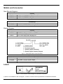
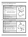
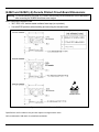
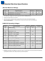
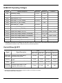
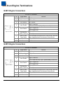
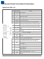
IS4813, IS4815, IS4823, and IS4825 Single-Line Laser Scan Engine Integration Guide Disclaimer Metrologic Instruments Inc. (Metrologic) reserves the right to make changes in specifications and other information contained in this document without prior notice, and the reader should in all cases consult Metrologic to determine whether any such changes have been made. The information in this publication does not represent a commitment on the part of Metrologic. Metrologic shall not be liable for technical or editorial errors or omissions contained herein: nor for incidental or consequential damages resulting from the furnishing, performance, or use of this manual. This document contains propriety information that is protected by copyright. All rights reserved. No part of this document may be photocopied, reproduced, or translated into another language without the prior written consent of Metrologic. © 2009 Metrologic Instruments Inc. All rights reserved. Web Address: www.metrologic.com Trademarks Metrologic and MetroSelect are trademarks or registered trademarks of Metrologic Instruments, Inc. or Honeywell International Inc. 3M is a trademark of 3M and/or its subsidiaries worldwide Other product names mentioned in this manual may be trademarks or registered trademarks of their respective companies and are the property of their respective owners. Patents Refer to page 38 for a list of patents. Table of Contents Introduction Product Overview ...........................................................................................................................................1 Models and Accessories Non-Decode Engines................................................................................................................................2 Decode Engines........................................................................................................................................2 Labels .............................................................................................................................................................2 Components of the IS4800 Engine Series IS4813 and IS4815 Non-Decode Engine..................................................................................................3 IS4823 and IS4825 (-0) Decode Engine Assembly ..................................................................................3 IS4823 and IS4825 Bracketed (-1 and -2) Decode Engine Assembly ......................................................4 Assembly IS4823-2 and the IS4823-2.............................................................................................................................5 Mounting Specifications IS4813 and IS4815 Scan Engine Dimensions ................................................................................................6 IS4823 and IS4825 Bracketed (-1 and -2) Dimensions ..................................................................................7 IS4823 and IS4825 (-0) Decode Printed Circuit Board Dimensions ...............................................................8 Exit Beam Specifications ................................................................................................................................9 Enclosure Specifications Electrostatic Discharge (ESD) Cautions .................................................................................................10 Grounding ...............................................................................................................................................10 Power Supply..........................................................................................................................................10 Power Sequencing..................................................................................................................................10 Host Flex Cable ......................................................................................................................................11 Thermal Considerations..........................................................................................................................11 Printed Circuit Board Component Clearance..........................................................................................11 Magnetic Sensitivity ................................................................................................................................11 Airborne Contaminants and Foreign Materials .......................................................................................11 Beam Clearance .....................................................................................................................................12 Output Window Properties ......................................................................................................................12 Output Window Coatings ........................................................................................................................13 Output Window Angle .............................................................................................................................13 Field of View and Depth of Field ............................................................................... 16 Description Of IS4823 and IS4825 Operating Modes Activation Modes ..........................................................................................................................................17 Common Activation Mode Features..............................................................................................................17 Continuous Blinky Mode ...............................................................................................................................18 ii Sleep Mode...................................................................................................................................................18 Serial Configuration Mode......................................................................................... 19 Abbreviated ASCII Table ..............................................................................................................................20 General Design Specifications.................................................................................. 21 Operational ...................................................................................................................................................21 Mechanical....................................................................................................................................................21 Electrical .......................................................................................................................................................22 Environmental ...............................................................................................................................................22 Detailed Electrical Specifications Absolute Maximum Ratings ..........................................................................................................................23 IS4823 DC Operating Voltages.....................................................................................................................23 IS4825 DC Operating Voltages.....................................................................................................................24 Current Draw @ 25°C...................................................................................................................................24 Scan Engine Terminations IS4813 Pinout Connections ..........................................................................................................................25 IS4815 Pinout Connections ..........................................................................................................................25 Decode Printed Circuit Board Terminations USB Decode PCB, 3.3V ...............................................................................................................................26 USB Decode PCB, 5V ..................................................................................................................................27 TTL, RS232 3.3V / 5V...................................................................................................................................28 Flex Cable Specifications and Installation Guidelines ........................................... 29 Timing Diagrams Startup Condition Timing Diagram................................................................................................................30 Scan Sense Timing Diagram ........................................................................................................................31 Bar Code Element Time Calculation......................................................................... 32 Regulatory Compliance ............................................................................................. 33 Limited Warranty ........................................................................................................ 37 Patents ........................................................................................................................ 38 Index ............................................................................................................................ 39 Contact Information ................................................................................................... 41 Product Service and Repair ...................................................................................... 42 iii Introduction Product Overview The non-decode IS4813 and IS4815 laser scan engines are designed for direct integration into custom OEM devices equipped with a decoder. The engine’s small size is ideal for integration into mobile computers, handheld scanners, medical/diagnostic equipment, mobile printers, lottery terminals, ATMs and access control devices. For customer applications requiring decode functionality in addition to solid scan engine performance, the IS4823 and IS4825 models combine the miniature IS4813 and IS4815 engines with a decoder and an optional mounting bracket for a complete small package that provides integration flexibility to meet a variety of OEM applications. The IS4823 and IS4825 deliver aggressive scanning with a decoded output on all standard 1D bar code symbologies — including UPC, EAN, Code 39 and I 2 of 5 — as dense as 4 mil. The IS4823 and IS4825 models support TTL level RS232 or USB system interfaces. They can operate in standard trigger mode, as well as “blinky” mode for hands-free scanning. The laser scan engine series is equipped with a multitude of features including: • 100 Scans per second • Support for 3.3VDC input voltage (IS4813, IS4823) • Support for 5VDC input voltage (IS4815, IS4825) • A 650 nm bright laser diode • A narrow exit angle to provide precise beam positioning • Automatic (hardware) scan sense • A rugged die cast engine chassis with threaded mounting holes • An optional mounting bracket for integration flexibility (IS4823, IS4825) • A 10-pin (IS4813, IS4815) or 12-pin (IS4823, IS4825) ZIF connector with industry standard pinout for seamless integration into portable devices • Low mass property (see page 21) in an industry standard size • A wide sweep angle for scanning big bar codes up close For ease of integration and optimum engine performance, Metrologic has designed a Software Development Kit (SDK) for the IS4813 and the IS4815. Contact a customer service representative or sales representative for additional information (see page 41). Notes: The manufacturer of the end equipment must register with agencies such as the Food and Drug Administration (FDA). The specifications required for registration are not obtainable until the OEM manufacturer uses the IS4800 series scan engine in its final configuration. Therefore, it becomes the responsibility of the manufacturer who incorporates the scan engine into their product to comply with all federal laser safety regulations. The manufacturer must submit a Laser Product Report for the FDA in the US. THIS DEVICE DOES NOT COMPLY WITH 21 CFR 1040. USE ONLY AS COMPONENT. 1 Models and Accessories Non-Decode Engines Options Model IS4813 IS4815 Description Non-Decode, 3.3VDC Scan Engine Non-Decode, 5VDC Scan Engine Accessories Part Number 19-07335 Description Flex Cable, 10-POS, 67.5 mm Length Decode Engines Options Base Model IS4823 IS4825 Description 3.3VDC Scan Engine with Decode PCB 5VDC Scan Engine with Decode PCB Model and Kit Delineation Figure 1. IS4823/IS4825 Model and Kit Delineation Accessories Part Number 19-00329 19-07335 Description Flex Cable, 12-POS, 80 mm Length Flex Cable, 10-POS, 67.5 mm Length Labels Figure 2. Serial Number Label (Enlarged For Illustration Purposes) † Option is not available for sale in all regions. Contact a customer service representative for additional information. 2 Components of the IS4800 Engine Series IS4813 and IS4815 Non-Decode Engine Item Description 1 Pin Locator Holes (see page 6) 2 Threaded Mounting Points (see page 6) Item Location Exit Beam Location, Laser Light Aperture 3 AVOID EXPOSURE! – LASER LIGHT IS EMITTED FROM THIS APERTURE. 4 Flex Cable, 10-POS 5 ZIF Connector, 10-Pin 6 Printed Circuit Board and Shield 7 Die Cast Chassis Figure 3. IS4813/IS4815 IS4823 and IS4825 (-0) Decode Engine Assembly Item Description 1 Decode Printed Circuit Board 2 ZIF Connector, 12-PIN 3 Flex Cable, 12-POS 4 Pin Locator Holes (see page 6) 5 IS4813 or IS4815 Laser Scan Engine Item Location Exit Beam Location, Laser Light Aperture 6 AVOID EXPOSURE! – LASER LIGHT IS EMITTED FROM THIS APERTURE. 7 Threaded Mounting Points (see page 6) 8 Flex Cable, 10-POS Figure 4. IS4823-0/IS4825-0 3 IS4823 and IS4825 Bracketed (-1† and -2) Decode Engine Assembly Item Description 1 Flex Cable, 12-POS 2 Flex Cable, 10-POS 3 ZIF Connector, 10-PIN 4 Exit Beam Location, Laser Light Aperture AVOID EXPOSURE! – LASER LIGHT IS EMITTED FROM THIS APERTURE 5 IS4813 or IS4815 Laser Scan Engine Item Location Figure 5. IS4823-1/IS4825-1 Assembled† 6 ZIF Connector, 12-PIN 7 Decode Printed Circuit Board 8 0.10 Dia. Clearance Holes for Mounting, 2 Pls. 9 M2 x 0.4 Threaded Bosses for Mounting, 3 Pls. 10 Bracket 11 Screw, M1.2 – 6.36 mm T3, Thread Forming 12 Screw, M1.6 x 35 – 5 mm Philips, Stainless Steel with Patch, 2 Pls. Figure 6. IS4823-2/IS4825-2 Unassembled † Option is not available for sale in all regions. Contact a customer service representative for additional information. 4 Assembly IS4823-2 and IS4825-2 Figure 7. IS4823-2/IS4825-2 Assembly Item 1 2 3 4 5 6 7 8 Description Bracket, Base Screw, M1.6 x 35 – 5 mm, Philips Stainless Steel with Patch IS4813 or IS4815 Scan Engine Flex Cable, 10-POS Decode Printed Circuit Board Flex Cable, 12-POS Bracket, PCB Locking Bar Screw, M1.2 – 6 mm, T3, Thread Forming Tools Required ® Torx Screw Driver Phillips Screw Driver Qty. 1 2 1 1 1 1 1 2 Size T3 00 5 Mounting Specifications IS4813 and IS4815 Scan Engine Dimensions The engine has two M1.6 tapped holes on the bottom of the chassis for mounting the engine with screws. Two additional blind holes are provided on the bottom of the engine for keying purposes to assist with engine alignment (see figure below). Warning: The limited warranty (on page 37) is void if the following recommendations are not adhered to when mounting the IS4800 series laser scan engine. Follow the guidelines listed below when securing the engine to non-metallic or metallic mounting surfaces. For a non-metallic mounting surface: • Use non-magnetic M1.6 x .35 stainless steel screws. • Do not exceed 1.35 ± .09 cm-kg [ 1.17 ± .08 in-lbs. ] of torque during screw installation. • Use a minimum mount thickness of 3 mm. • Use safe ESD practices when handling and mounting the engine. For a metallic mounting surface: • The die-cast engine chassis is at +Vcc. Use an insulator between the engine chassis and the host (.005" thick PR4, or equivalent). • Use non-metallic nylon or equivalent M1.6 x .35 screws. • Do not exceeding 1.35 ± .09 cm-kg [ 1.17 ± .08 in-lbs. ] of torque. • Use a minimum mount thickness of 3 mm. • Use safe ESD practices when handling and mounting the engine. Figure 8. IS4813 and IS4815 Engine Dimensions Specifications are for reference only and are subject to change without notice. 6 IS4823 and IS4825 Bracketed (-1 and -2) Dimensions The engine bracket has three M2 x 0.4 threaded inserts on the bottom for mounting the assembly with screws. Two through holes are also provided as an alternative mounting method. Warning: The limited warranty (on page 37) is void if the following recommendations are not adhered to when mounting the IS4800 series laser scan engine. When securing the engine by utilizing the three M2 threaded inserts: • Use M2 x 0.4 Phillips Pan Head, Type AB, Steel, Zinc Clear or equivalent screws. • Do not exceed 2.88 cm-kg [ 2.5 in-lb ] of torque when securing the engine assembly to the host. • Use a minimum mount thickness of 3 mm. • Use safe ESD practices when handling and mounting the engine assembly. Figure 9. IS4823/IS4825 Bracketed (-1 and -2) Dimensions Specifications are for reference only and are subject to change without notice. 7 IS4823 and IS4825 (-0) Decode Printed Circuit Board Dimensions Warning: The limited warranty (on page 37) is void if the following recommendations are not adhered to when mounting the IS4800 series laser scan engine. When securing the decode board: • 3M™ 4032 1/32" double-coated urethane foam tape (or equivalent). • Use safe ESD practices when handling and mounting the decode board. Figure 10. IS4823/IS4825 Decode PCB Dimensions Specifications are for reference only and are subject to change without notice. 3M is a trademark of 3M and/or its subsidiaries worldwide. 8 Exit Beam Specifications Figure 11. IS4800 Series Exit Beam Specifications See page see pages 12 - 15 for information on window material specifications and enclosure design considerations. Specifications are subject to change without notice. 9 Enclosure Specifications The IS4800 laser scan engine series was specifically designed for integration into custom housings for OEM applications. The scan engine’s performance will be adversely affected or permanently damaged when mounted in an unsuitable enclosure. Note: THIS DEVICE DOES NOT COMPLY WITH 21 CFR 1040. USE ONLY AS COMPONENT. The limited warranty (on page 37) is void if the following considerations are not adhered to when integrating an IS4800 series scan engine into a system. Electrostatic Discharge (ESD) Cautions ESD has the ability to modify the electrical characteristics of a semiconductor device, possibly degrading or even destroying the device. ESD also has the potential to upset the normal operation of an electronic system, causing equipment malfunction or failure. The scan engine has exposed electrical components. • DO NOT touch the leads of the visible laser diode (VLD) or other components. • ALWAYS use grounding wrist straps and a grounded work area when handling the engine. • Mount the engine in a housing that is designed for ESD protection and stray electric fields. Grounding If the scan engine is going to be installed in a grounded host: • The die-cast engine chassis is at +Vcc. Use an insulator between the engine chassis and host. • Use non-metallic nylon or equivalent screws. Power Supply The IS4813/IS4815 non-decode engines are powered from the host device through the 3.3V or 5V and GND pins of the engine’s 10-Pin ZIF connector. IS4823/IS4825 decode engine assemblies are powered from the host device through the 3.3V or 5V and GND pins of the 12-Pin ZIF connector on the decode board. This voltage must be maintained within the specified voltage range (see electrical specifications on page 22) at the engine’s PCB. Voltage drops in the host flex cable must be taken into account (see Flex Cables on page 11). Power Sequencing The IS4813/IS4815 non-decode engines are powered from the 3.3V or 5V power signal on the 10-Pin ZIF connector and the IS4823/IS4825 decode engine assemblies are powered from the 3.3V or 5V power signal on the decode board. Most of the host signals (signals present on the ZIF connector) are relative to this voltage. Not all of these signals are overvoltage tolerant. Care must be taken to ensure that the relationship between 3.3V or 5V and the host signals are always met (see electrical specifications on page 22). See page 23 - 24 for additional electrical specifications. See page 26 - 28 for additional pinout information. 10 Flex Cables Note: To ensure optimum engine stability, use the flex cables shipped with the scan engine. The host flex cable is used to carry power and data signals between the engine and the host system. The flex cable should allow for a minimal voltage drop and maintain a good ground connection between the host and the engine. In terms of grounding and voltage drop, a shorter cable is better. The 10-POS flex cable used to connect the engine to the host or the engine to the decode PCB must be equal to or less than 67.5 mm in length. The 12-POS flex cable used to connect the decode PCB to the host must be equal to or less than 80 mm in length. In addition to power, the flex cable also carries the digital signals required for communication. The cable design is especially important in USB interface applications due to the relative high speed of the USB signals. The impedance of the cable should match, or be as close as possible to the impedance of the USB driver (approximately 45 ohms per trace). The routing of the flex cables plays a critical role in the system design. The host flex cable should be routed away from high frequency devices that have frequencies that can couple onto the flex cable and cause potential data corruption or unwanted electromagnetic inference (EMI). Thermal Considerations The IS4800 laser scan engine series is qualified over the specified operational temperatures (0°C to 40°C) for all operating modes. Make sure ambient temperatures do not exceed this range in order to guarantee operation. Operating the IS4800 in continuous mode for an extended period may produce considerable heating. This mode should be limited and sufficient airflow should be provided whenever possible to minimize internal heating. Excessive heating may potentially damage the IS4800 engine. Printed Circuit Board (PCB) Component Clearance Warning: When designing the IS4800 into the final product, eliminate all possible dangers of shorting sensitive electronic components in the IS4800 engine. A short could enable the scan engine to emit Class 3R radiation. Any CDRH filing will require a disclosure of the design ensuring a method to mitigate a potential short. Magnetic Sensitivity The scan engine can be negatively affected by magnetic fields: • Use only non-magnetic screws and locating pins. • Do not mount the engine within 1.00" (25.4 mm) of any magnetic materials. Airborne Contaminants and Foreign Materials The scan engine has very sensitive miniature electrical and optical components that must be protected from airborne contaminants and foreign materials. In order to prevent permanently damaging the scan engine and voiding the limited warranty (on page 37), the scan engine enclosure must be: • Sealed to prevent infiltration by airborne contaminants and foreign materials such as dust, dirt, smoke, and smog. • Sealed to protect against water, humidity and be non-condensing. See page 23 - 24 for additional electrical specifications. See page 26 - 28 for additional pinout information. 11 Beam Clearance • Keep the scan engine’s beam sweep free from obstructions. For detailed information on the exit beam angle and location, please refer to Exit Beam Specifications on page 9. • A dark matte-finish on the internal walls of the housing can be utilized to avoid internal beam reflections. Output Window Properties Note: Contact a customer service representative to coordinate the best window material required to maintain laser safety requirements for your application. An improperly placed window has the serious potential to reduce the scan engine’s performance. Careful consideration must be made when designing the output window’s distance and angle placement relative to the scan engine’s exit beam and chassis. Follow these guidelines when designing the output window. • Acceptable window materials include; Acrylic (cast or molded), float glass, CR-39, and Polycarbonate. Note: Molded polycarbonate is high in strength; however, it might exhibit a phenomenon called birefringence. Birefringence refers to multiple indices of refraction within one material. This condition will induce polarization effects that can be detrimental to scan performance of the engine. Check with a representative before utilizing a transparent polycarbonate material for the output window. 12 • The exit window material should have a spectral transmission of at least 85% from 640 nm to 690 nm and should block shorter wavelengths. • Red cell-cast acrylic is recommended. • The exit window should exhibit a wavefront distortion (transmission) of no more than 0.2 wavelengths peak-to-valley maximum over any 0.08" diameter within the clear aperture. • The clear aperture of the output window should extend beyond the 54° beam sweep (see Exit Beam Specifications on page 9). • It should have a 60-40 surface quality and be optically flat, clear, and free of scratches, pits, or seeds. If possible, recess the window into the housing for protection or apply a scratch resistance coating (see Output Window Coatings on page 13). • Apply an anti-reflective coating to the window surfaces to reduce the possibility of reflective light interfering with the engine’s performance due to the window angle (see Output Window Coatings on page 13). Output Window Coatings • Anti-Reflection An anti-reflective coating can be applied to the inside and/or outside of the window to reduce the possibility of internal beam reflections interfering with the scan performance of the engine. If an antireflective coating is applied, it is recommended that it be on both sides of the window providing a 0.5% maximum reflectivity on each side from 640 to 690 nanometers at the nominal window tilt angle. The coating must also meet the hardness adherence requirements of MIL-M-13508. • Polysiloxane Coating Apply a polysiloxane coating to the window surface to help protect the window from surface scratches and abrasions that may interfere with the scan performance of the engine. Recessing the window into the housing can also provided added protection against surface damage such as scratches and chips. If an anti-reflective coating is used, there is no need to apply a polysiloxane coating. Output Window Angle Note: An improperly placed window has the serious potential to reduce the scan engine’s performance. Careful consideration must be made when designing the output window’s distance and angle placement relative to the scan engine’s exit beam and chassis. It is important that angle of the window not be perpendicular to the exit beam of the scan engine. The angle of the window can cause the beam’s laser light to reflect off the inside of the window back into the scan engine’s optics ultimately degrading the engine’s performance. Refer to the Figure 12 on page 14 and Figure 13 on page 15 for specifications on the minimum allowable window angle required to avoid reflective beam interference. 13 Minimum Allowable Window Position Required To Avoid Detrimental Internal Reflective Beam Interference at Positive Exit Beam Angle Tolerance +2.5° Minimum Projected Distance (mm) from the Engine’s Base to the Window’s Internal Surface (L) 5.0 +2.5° 10.0 14.5° +2.5° 15.0 10.5° +2.5° 20.0 8.0° +2.5° 25.0 7.0° +2.5° 30.0 6.5° +2.5° 35.0 6.0° +2.5° 40.0 5.5° +2.5° 45.0 5.0° +2.5° 50.0 5.0° Exit Beam Elevation Angle α Figure 12. Specifications are subject to change without notice. 14 Minimum Window Angle θ 28.0° Minimum Allowable Window Position Required To Avoid Detrimental Internal Reflective Beam Interference at Negative Exit Beam Angle Tolerance Exit Beam Depression Angle β Minimum Projected Distance (mm) from the Engine’s Base to the Window’s Internal Surface (M) Minimum Window Angle θ -2.5° 5.0 23.5° -2.5° 10.0 16.5° -2.5° 15.0 12.5° -2.5° 20.0 10.5° -2.5° 25.0 9.0° -2.5° 30.0 8.0° -2.5° 35.0 7.5° -2.5° 40.0 7.0° -2.5° 45.0 6.5° -2.5° 50.0 6.0° Figure 13. Specifications are subject to change without notice. 15 Scan Engine Field of View and Depth of Field Field of View Distance from Engine Face Width of Field of View 50 mm (2") 57 mm (2.2") 254 mm (10") 264 mm (10.4") See page 9 for detailed information on the engine's exit beam specifications. Based on a .33 mm (13.0 mil) bar code. Figure 14. Typical Field of View Depth of Field vs. Minimum Bar Code Element Bar Code Element Width 1D Depth of Field* (In the Field of View) .13 mm 5.2 mil Start (From Engine Face) 70 mm (2.75") End (From Engine Face) 95 mm (3.75") Total 25 mm (1.00") .19 mm 7.5 mil 57 mm (2.25") 171 mm (6.75") 114 mm (4.50") .26 mm 10.4 mil 50 mm (2.00") 210 mm (8.25") 160 mm (6.25") .33 mm 13.0 mil 50 mm (2.00") 254 mm (10.00") 204 mm (8.00") .49 mm 19.5 mil 75 mm (2.95") 300 mm (11.81") 225 mm (8.86") * For non-decode IS4813 and IS4815 engines, depth of field data is for reference only. Actual values may vary depending on environmental conditions, host hardware, and decoding software. Depth of field data was measured at 25°C under typical indoor lighting. Performance may vary depending on testing conditions. Specifications are subject to change without notice. 16 Descriptions of IS4823 and IS4825 Operating Modes Activation Modes The following activation modes initiate the engine’s laser and motor drive circuitry for bar code scanning. Activate Scanning with the External Trigger (Default). An external I/O pin is used to enable the scanning cycle. A High-to-Low transition on the I/O signal is used to activate scanning. The signal must be deactivated (HIGH) and re-activated for subsequent scanning cycles. The scanning cycle is terminated based on the default period of time (2 seconds), a variable period of time, when the I/O signal is deactivated (Low-to-High), or when a bar code is scanned and transmitted. Activate Scanning on Receipt of the <DC2> Character A received <DC2> character initiates the scanning cycle. The scanning cycle is terminated based on the default period of time (2 seconds), variable laser timeout selected, or when a bar code is scanned and transmitted. Activate/Deactivate Scanning Using D/E A received ‘E’ character initiates the scanning cycle. The scanning cycle is terminated based on the default period of time (2 seconds), variable laser timeout selected, or receipt of a ‘D’ or when a bar code is scanned and transmitted. Activate Scanning with Address A configurable address character is used to initiate scanning. The scanning cycle is terminated based on the default period of time (2 seconds), variable laser timeout selected, or when a bar code is scanned and transmitted. Common Activation Mode Features The following configurable activation mode features are available for the IS4823 and IS4825. Variable Laser-On Timeout (1-second Increments) A configurable time increment selected as the scanning laser–on time. Allow Full Laser-On Cycle The laser stays on for a full cycle even when a bar code is scanned and transmitted. Blinky Mode The scanner will blink for 60 cycles (approximately 30 seconds) once the scanning cycle is activated. 17 Transmit “NO READ” Message on Laser Timeout If the scanning cycle terminates without scanning a bar code during the cycle, a “NO READ” message is transmitted with the termination of the scanning cycle. Activate the LED During the “NO READ” Transmission The LED is activated with the “NO READ” message. The LED is also activated after a successful scan. Enable RTS “NO READ” Pulse A configurable RTS pulse width transmitted after the “NO READ” message has been transmitted. Detect and Notify Mode The external I/O pin used in the default activation mode is monitored during the inactive laser cycles. An <SI> is transmitted when the I/O is active and an <SO> when it is inactive. Once the scanning activation cycle is started, the external I/O monitoring status is maintained until the scanning cycle is terminated regardless of the actual I/O level. Continuous Blinky Mode The scanner will continuously blink on and off, turning the scanning cycle on and off for all normal scanner operations. If a bar code is scanned and transmitted, the same symbol timeout is maintained throughout the cycle preventing additional scans of the same bar code when the scanner is in default mode. Sleep Mode Sleep Mode is a power saving mode that can be configured to occur in 10-second increments. 18 Serial Configuration Mode The IS4823/IS4825 can be configured by scanning configuration bar codes† or by serial commands sent from the host device. With serial configuration, each command sent to the engine is the ASCII representation of each numeral in the configuration bar code (see Figure 15). The entire numeric string is framed with an ASCII [stx] and an ASCII [etx]. Do Not Include in the Command ³ 1 0 0 1 0 4 Include in the Command Figure 15. Example 1: Feature Host Command String Sent to the Engine ASCII Representation (Hexadecimal Values) Disable Codabar [stx]100104[etx] 02h 31h 30h 30h 31h 30h 34h 03h [ack] If the command sent to the engine is valid, the engine will respond with an [ack]. [nak] If the command sent to the engine is invalid, the engine will respond with a [nak] then automatically exit serial configuration mode. All the settings chosen in the failed serial configuration session will be lost. There is a 20-second window between commands. If a 60-second timeout occurs, the engine will send a [nak]. Enter Serial Configuration Mode To enter serial configuration mode, send the following command, [stx]999999[etx]. The engine will not scan bar codes while in serial configuration mode. Note: Serial configuration mode uses the current Baud Rate, Parity, Stop Bits and Data Bits settings that are configured in the engine. The default settings of the engine are 9600 bits-per-second, space parity, 2 stop bits, 7 data bits, and no flow control. If a command is sent to the engine to change any of these settings, the change will not take effect until after serial configuration mode is exited. Exit Serial Configuration Mode To exit serial configuration mode, send the following command, [stx]999999[etx]. The engine will respond with an [ack]. † Configuration bar codes are located in the MetroSelect Single-Line Guide, PN 00-02544 and the Supplemental MetroSelect Configuration Guide, PN 00-05268. 19 Example 2: The following sample illustrates the serial command sequence for configuring the engine for the factory default settings, disabling Code 128 scanning, and adding a “G” as a configurable prefix. Commands for features that require sequences of multiple bar codes for activation (i.e. prefixes, suffixes, and timeout features) should be sent in the same order that they are normally scanned. Feature Host Command ASCII Representation Engine Response Enter Configuration Mode [stx]999999[etx] 02h 39h 39h 39h 39h 39h 39h 03h [ack] or 06h Load Defaults [stx]999998[etx] 02h 39h 39h 39h 39h 39h 38h 03h [ack] or 06h Disable Code 128 [stx]100103[etx] 02h 31h 30h 30h 31h 30h 33h 03h [ack] or 06h Configure Prefix #1 [stx]903500[etx] 02h 39h 30h 33h 35h 30h 30h 03h [ack] or 06h Code Byte 0 [stx]0[etx] 02h 30h 03h [ack] or 06h Code Byte 7 [stx]7[etx] 02h 37h 03h [ack] or 06h Code Byte 1 [stx]1[etx] 02h 31h 03h [ack] or 06h Exit Configuration Mode [stx]999999[etx] 02h 39h 39h 39h 39h 39h 39h 03h [ack] or 06h Abbreviated ASCII Table 20 Character Hex Value Decimal Value [STX] 02h 2 [ETX] 03h 3 [ACK] 06h 6 [NAK] 15h 21 0 30h 48 1 31h 49 2 32h 50 3 33h 51 4 34h 52 5 35h 53 6 36h 54 7 37h 55 8 38h 56 9 39h 57 General Design Specifications Operational Light Source: Visible Laser Diode (VLD) @ 650 nm Laser Power: 1 mW Depth of Scan Field: 50 mm – 254 mm (2" – 10") for 0.33 mm (13 mil) bar codes Width of Scan Field: 57 mm (2.2") @ 50 mm (2") from engine face 264 mm (10.4") @ 254 mm (10") from engine face Scan Speed: 100 Scan Lines per Second Typical Scan Pattern: Single Scan Line Minimum Bar Width: 0.10 mm (4.0 mil) Symbologies Supported: IS4813 and IS4815 Software Dependent IS4823 and IS4825 Autodiscriminates All Standard 1D Symbologies System Interface: IS4823 and IS4825 USB, TTL RS232 Print Contrast: 35% Minimum Reflectance Difference Number of Characters IS4813 and IS4815 Read: IS4823 and IS4825 Decode Dependent Up to 80 data characters (Maximum) Roll, Pitch, Yaw 42°, 68°, 52° Mechanical Dimensions: See pages 6 – 8 for detailed specifications. IS4813 / IS4815 Non-Decode Engine Weight (Maximum): IS4823 / IS4825 Bracketed (-1) Assembly Termination: 8 g (0.282 oz) 15 g (0.529 oz) IS4823 / IS4825 Non-Bracketed (-1) Assembly 10 g (0.353 oz) IS4813 / IS4815 Non-Decode Engine 10-PIN ZIF Connector IS4823 / IS4825 Decode PCB 12-PIN ZIF Connector Enclosure and See pages 6 – 13 for detailed specifications on enclosure and Mounting: mounting guidelines. Specifications are subject to change without notice. 21 Electrical IS4813 IS4815 Input Voltage: 3.3VDC ± 0.3VDC 5.0VDC ± 5% Power Consumption: 400 mW 350 mW Typical Operating Current: < 120 mA @ 3.3VDC < 70 mA @ 5.0VDC Standby Current: < 30 mA @ 3.3VDC < 15 mA @ 5.0VDC IS4823 IS4825 USB TTL USB TTL, RS232 Peak Operating Current: 170 mA 150 mA 135 mA 135 mA Idle Current: 75 mA 50 mA 72 mA 45 mA Sleep Current: 65 mA 5.5 mA 53 mA 15 mA Suspend Current (USB): 5.5 mA N/A 0.30 mA N/A Power Down Current (TTL): 5.5 mA See pages 33 - 36 for regulatory compliance information. Environmental Operating Temperature: -0°C to 40°C (32°F to 104°F) Storage Temperature: -40°C to 70°C (-40°F to 158°F) Humidity: 5% to 95% relative humidity, non-condensing Vibration Protection: 7G over 10 – 500 Hz Specifications are subject to change without notice. 22 15 mA Detailed Electrical Specifications Absolute Maximum Ratings Signal * Signal Description Minimum Maximum Vinput † Voltage Applied to Any input pin (except D+ and D-) * -0.3V Vin Voutput Voltage Applied to Any output pin ** -0.3V Vin + 0.3V For USB version, Voltages on D+ and D- signal must conform to USB Specification ** Voutput must be less than 5.5V for all pins † If the Vinput signal is greater than VIN, current will flow from the input to the VIN pin through the pull up resistors on the engine. In Suspend Mode, this may cause current to flow into the USB power. This is not recommended. IS4823 DC Operating Voltages Signal Minimum Maximum Operating Voltage 3.0V 3.6V VIH(1) Input High (RX, CTS) 2.5V VIL(1) Input Low (RX, CTS) VIH(2) Input High (TTL_INV, nWake) VIL(2) Input Low (TTL_INV, nWake) VIH(3) Input High (EXT. Trigger) VIL(3) Input Low (EXT. Trigger) VIN Signal Description VOH(1) Output High Voltage (TX,RTS) VOL(1) Output Low Voltage (TX,RTS) VOH(2) Output High Voltage (nBeeper, nGoodRead) VOL(2) Output Low Voltage (nBeeper, nGoodRead) VOH(3) Output High Voltage (Power down) VOL(3) Output Low Voltage (Power down) Condition 0.8V 0.8 x Vin 0.8V 0.8 x Vin 0.8V 0.8 x Vin Isource = 16 mA 0.14 x Vin *** 3.6V 1.6V *** Isink = 16 mA Isink = 25 mA 3.6V 0.2V Isink = 8 mA *** PWRDWN, nGoodRead, and nBeeper are open drain outputs w/ 100K pull-ups to VIN. Actual VOH will be determined by the parallel resistance of the 100K pull up and any external impedance. 23 IS4825 DC Operating Voltages Signal Minimum Maximum Operating Voltage 4.75V 5.25V VIH(1) Input High (RX, CTS) 2.5V VIL(1) Input Low (RX, CTS) VIH(2) Input High (TTL_INV, nWake) VIL(2) Input Low (TTL_INV, nWake) VIH(3) Input High (EXT. Trigger) VIL(3) Input Low (EXT. Trigger) VIN Signal Description Condition 0.8V 0.8 x Vin 0.8V 0.8 x Vin 0.8V VOH(1) Output High Voltage (TX,RTS) 0.8 x Vin VOL(1) Output Low Voltage (TX,RTS) VOH(2) Output High Voltage (nBeeper, nGoodRead) VOL(2) Output Low Voltage (nBeeper, nGoodRead) VOH(3) Output High Voltage (Power down) VOL(3) Output Low Voltage (Power down) Isource = 16 mA 0.14 x Vin Isink = 16 mA 3.6V or 5.5V *** 1.6V Isink = 25 mA 3.6V or 5.5V *** 0.2V Isink = 8 mA *** PWRDWN, nGoodRead, and nBeeper are open drain outputs w/ 100K pull-ups to VIN. Actual VOH will be determined by the parallel resistance of the 100K pull up and any external impedance. Current Draw @ 25°C USB Signal Continuous Scan mode Stand By Sleep Suspend Mode (USB) Signal Description Average current draw during continuous scan mode* Average current draw while in idle mode Average current draw while in sleep mode Average current draw in USB suspend (USB version only) TTL VIN = 3.3V VIN = 5V VIN = 3.3V VIN = 5V 150 mA 130 mA 130 mA 130 mA 60 mA 72 mA 50 mA 45 mA 50 mA 53 mA 5.5 mA 15 mA 5.5 mA 0.3 mA N/A N/A * Continuous Scan Mode current will vary based on object size, distance, and type. The numbers listed above are typical. 24 Scan Engine Terminations IS4813 Engine Connections 10-Pin ZIF Connector Figure 16. IS4813 Pin Signal Name Function 1 No Connect No Connect 2 Power, VCC 3.3V ± 0.3V 3 No Connect No Connect 4 Laser Enable* 5 Scan Enable* 6 Digitized Bar Pattern, Data Out 7 Start of Scan, Scan Sense 8 and 9 Ground 10 No Connect High = Laser OFF Low = Laser ON, only if pin 5 (scan enable) is also Low High = Engine OFF Low = Engine ON High = Bar Low = Space Level changes from high to low, or low to high, when the laser changes direction at the start of the scan line. Power Ground No Connect IS4815 Engine Connections 10-Pin ZIF Connector Pin Signal Name 1 No Connect No Connect 2 Power, VCC 5.0V ± 5% 3 No Connect No Connect 4 Laser Enable* 5 Scan Enable* 6 Digitized Bar Pattern, Data Out 7 Start of Scan, Scan Sense 8 and 9 Ground 10 No Connect Figure 17. IS4815 Function High = Laser OFF Low = Laser ON, only if pin 5 (scan enable) is also Low High = Engine OFF Low = Engine ON High = Bar Low = Space Level changes from high to low, or low to high, when the laser changes direction at the start of the scan line. Power Ground No Connect * See Timing Diagrams on page 30. 25 Decode Printed Circuit Board Terminations USB Decode PCB, 3.3V 12-Pin ZIF Connector Pin Signal Name Function 1 No Connect 2 +3.3V Power: Supply Voltage Input, +3.3V ± 0.3V 3 GND Ground: Power and Signal Ground 4 D- 5 <reserved> 6 D+ 7 <reserved> Pin Function Reserved 8 PWRDWN Output: Active High = IS4823 is in Power Down Mode 9 nBEEPER Output: Active Low, Signal Capable of Sinking Current See Detailed Electrical Specifications starting on page 23. 10 nGood Scan 11 nEXT Wake 12 EXT Trig No Connection Input: USB D- Signal Pin Function Reserved Input: USB D+ Signal Output: Active Low, Signal for Sinking Current (Good Scan) See Detailed Electrical Specifications starting on page 23. Input: Active Low, Wakes Engine From Suspend or Sleep Mode Input: Active Low, Signal Used as Trigger Input to Activate the Engine 10-Pin ZIF Connector Pin Figure 18. 26 Signal Name 1 SDA 2 GND Function I C Data (Bi-Directional) – Devices Function as Auxiliary Devices Ground: Power and Signal Ground 3 GND Ground: Power and Signal Ground 4 Scan Sense 5 Data 6 Scan Enable 7 Laser Enable 8 NC 9 +3.3V 10 SCL 2 Level changes from High to low or low to high when the laser changes direction at the start of the scan line High = Bar Low = Space High = Engine OFF Low = Engine ON High = Laser OFF Low = Laser ON No Connection Power: Supply Voltage Input, +3.3V ± 0.3V I2C Data (Bi-Directional) – Devices Function as Auxiliary Devices USB Decode PCB, 5V 12-Pin ZIF Connector Pin Signal Name Function 1 No Connect 2 +5.0V Power: Supply Voltage Input, +5.0V ± 5% 3 GND Ground: Power and Signal Ground 4 D- 5 <reserved> 6 D+ 7 <reserved> Pin Function Reserved 8 PWRDWN Output: Active High = Engine is in Power Down Mode 9 nBEEPER Output: Active Low, Signal Capable of Sinking Current See Detailed Electrical Specifications starting on page 23. 10 nGood Scan Output: Active Low, Signal for Sinking Current (Good Scan) See Detailed Electrical Specifications starting on page 23. 11 nEXT Wake Input: Active Low, Wakes Engine from Power Down or Sleep Mode 12 EXT Trig No Connection Input: USB D- Signal Pin Function Reserved Input: USB D+ Signal Input: Active Low, Signal Used as Trigger Input to Activate the Engine 10-Pin ZIF Connector Pin Figure 19. Signal Name Function 2 1 SDA I C Data (Bi-Directional) – Devices Function as Auxiliary Devices 2 GND Ground: Power and Signal Ground 3 GND Ground: Power and Signal Ground 4 Scan Sense 5 Data 6 Scan Enable 7 Laser Enable 8 NC 9 +5.0V 10 SCL Level changes from High to low or low to high when the laser changes direction at the start of the scan line High = Bar Low = Space High = Engine OFF Low = Engine ON High = Laser OFF Low = Laser ON No Connection Power: Supply Voltage Input, +5.0V ± 5% I2C Data (Bi-Directional) – Devices Function as Auxiliary Devices 27 TTL, RS232, 3.3V / 5V 12-Pin ZIF Connector Pin Signal Name 1 TTLINV 2 Function Input: TTL RS232 Polarity Control with 33.2k ohm Pull-Up +3.3V or 5.0V Power: Supply Voltage Input, +3.3V ± 0.3V or +5.0V ± 5% 3 GND Ground: Power and Signal Ground 4 RxD Input: TTL Level RS232 Receive Data 5 TxD Output: TTL Level RS232 Transmit Data 6 CTS Input: TTL Level Clear to Send 7 RTS Output: TTL Level RS232 Request to Send 8 PWRDWN Output: Active High = IS4823 is in Power Down Mode 9 nBEEPER Output: Active Low, Signal Capable of Sinking Current See Detailed Electrical Specifications starting on page 23. 10 nGood Scan Output: Active Low, Signal for Sinking Current (Good Scan) See Detailed Electrical Specifications starting on page 23. 11 nEXT WAKE Input: Active Low, Signal Used to Bring Engine Out of Power Down 12 EXT Trig Input: Active Low, Signal Used as Trigger Input to Activate the Engine 10-Pin ZIF Connector Pin Figure 20. 1 SDA 2 GND Function I C Data (Bi-Directional) – Devices Function as Auxiliary Devices Ground: Power and Signal Ground 3 GND Ground: Power and Signal Ground 4 Scan Sense 5 Data 6 Scan Enable 7 Laser Enable 8 NC 9 10 28 Signal Name 2 Level changes from High to low or low to high when the laser changes direction at the start of the scan line High = Bar Low = Space High = Engine OFF Low = Engine ON High = Laser OFF Low = Laser ON No Connection +3.3V or 5.0V Power: Supply Voltage Input, +3.3V ± 0.3V or +5.0V ± 5% I2C Data (Bi-Directional) – Devices Function as Auxiliary SCL Devices Flex Cable Specifications and Installation Guidelines Figure 21. Flex Cable Specifications and Installation Guidelines Specifications are subject to change without notice. 29 Timing Diagrams Startup Condition Timing Diagram The timing diagram below illustrates the correct power up procedure for the IS4813 and IS4815 engines. Scan Enable and Laser Enable are host driven signals. The Scan Enable and Laser Enable signals should be kept LOW (ON) at power up. Scan Control and Laser Control are engine driven signals. The engine's onboard microcontroller drives the Scan Control and Laser Control signals so the engine's laser will not turn ON before the scan mirror starts moving. This allows the onboard microcontroller to sense immediately any malfunction with the engine's scan mirror, turning OFF the laser automatically regardless of the state of Laser Enable signal being received from the Host. To ensure scan data integrity the Scan Sense pulses are delayed for approximately 55 ms after the Laser Enable signal goes LOW (ON). To save power, turn OFF power to the engine after the scan is complete or when the engine is not scanning. To turn the engine's power OFF, the Laser Enable signal from the host should be held HIGH (OFF) before turning OFF power to the engine. Figure 22. IS4813/IS4815 Timing Diagram, Startup Condition 30 Scan Sense Timing Diagram The Scan Sense signal is a 50% duty cycle square wave with the transitions from HIGH to LOW indicating a change in the scan direction of the scanning beam (see Figure 22). Valid scan data occurs between the HIGH to LOW transitions. Figure 23 illustrates the condition in which power to the engine stays ON. Scan Enable and Laser Enable signals are controlled separately by the host. The onboard microcontroller is programmed to ensure the engine's scan mirror is moving before the laser is turned ON. This allows the host to turn ON Scan Enable and Laser Enable signals simultaneously without worrying about laser safety. The Laser Enable signal can even be set LOW (ON) before the Scan Enable signal goes LOW (ON). If the scan mirror is moving and Laser Enable signal goes LOW (ON), the onboard microcontroller immediately turns ON the laser. If Laser Enable signal is LOW (ON) and Scan Enable signal is HIGH (OFF) then the onboard microcontroller waits for the Scan Enable signal to go LOW (ON) and ensures the scan mirror has started moving before turning the laser ON. The Scan Sense line remains HIGH until the Scan Enable signal goes LOW (ON). After approximately 55 ms, it toggles with a 50% duty cycle representing the scan sweep direction. Valid scan data appears within these pulses. Figure 23. Timing Diagram Scan Enable and Laser Enable Controlled Separately 31 Bar Code Element Time Calculation Realization of the full depth of field for all bar codes given in the specification is based on the ability of the decoding hardware to resolve a varying range of minimum element times. The minimum element time calculation for a given bar code size at a given distance is shown in Equation 1 (below). Minimum Element Time = (Element Size / Spot Speed) Equation 1. Example: Bar code Size = 5.2 mil Spot Speed @ 95 mm from face = 650 inches/second Minimum Element Time = (0.0052 inches/ (650 inches/second)) = 8.0 µsec 32 Regulatory Compliance THIS DEVICE DOES NOT COMPLY WITH 21 CFR 1040. USE ONLY AS COMPONENT. The IS4800 Series Laser Scan engines are designed to meet the requirements of IEC Class 2 in accordance with IEC 60825-1:1993+A1:1997+A2:2001. IEC Class 2 is defined as follows: Emission Duration: Greater than 0.25 seconds Accessible Emission Limit: Less than 0.001 W (1.0 milliwatt) average radiant power The IS4800 laser scan engine series is registered with the Center for Devices and Radiological Health as a laser “component”. The addition of shutdown controls, labeling and informational requirements are necessary to achieve compliance with the performance standard published in the Code of Federal Regulations (CFR), Title 21 Parts 1040.10 and 1040.11. It is the responsibility of the manufacturer who incorporates the scan engine into their product to provide the additional performance, labeling, and informational requirements necessary to comply with all federal laser safety regulations. The specifications required for agency approval are not obtainable until the IS4800 engine is used in its final configuration. Metrologic is unable to fulfill these requirements because the scan engine will operate differently depending upon where it is used as a component. The following information concerning the scan engine appears on the shipping label: THIS DEVICE DOES NOT COMPLY WITH 21 CFR 1040. USE ONLY AS A COMPONENT. Manufacturers incorporating unmodified IS4800 engines into their product may reference the following accession number on items in their Laser Product Report that request information concerning features inherent in the IS4800 engine design. Accession Number: 0620138-00 It is the responsibility of the manufacturer who incorporates the scan engine into their product to obtain country specific regulatory compliance prior to the sale of the product. Refer to one of the following sections for further explanation. United States: Refer to page 34 for more information. Canada: Refer to page 35 for more information. Europe: Refer to page 35 for more information. 33 United States Laser Safety To assist with the FDA filing requirements (refer to Regulatory Requirements), Metrologic has registered the scan engine with the FDA as a component. Customers can contact CDRH at the following address: Food and Drug Administration Center for Devices and Radiological Health Light Products Branch (HFX-312) Office of Compliance 2098 Gaither Road Rockville, MD 20850 Tel: 301-594-4654 www.fda.gov/cdrh Requirements for laser products are described in CFR (Code of Federal Regulation) Title 21, part 1040.10 & 1040.11 from the Government Printing Office. Copies can be ordered by calling 202-512-1800, ordering on line from www.access.gpo.gov or writing to: Superintendent of Documents PO Box 371954 Pittsburgh, PA 15250-7954 Note: State and local governments may regulate the use products containing lasers. The manufacturer should consult the applicable government regulations for more information. Copies of Product Reporting Guides, other guides, and related documents are available as PDF documents from the CDRH website at: www.fda.gov/cdrh/comp/eprc.html. Additional resources include the Division of Small Manufacturers, International and Consumer Assistance (DSMICA) in Rockville, Maryland at 1-800-638-2041. EMC Certain combinations of scan engines and associated electronics may require testing to insure compliance with the following Federal Communications Commission regulation: 47 CFR Part 15 Note: When using the scan engine with RF equipment, modems, etc. may require examination(s) to the standard(s) for the specific equipment combination. It is the manufacturers’ responsibility to comply with the applicable federal regulation(s). The IS4800 series laser scan engine is designed to meet EN55022 Radiated Class B emission limits. The engine was installed in a representative system and tested for compliance. 34 Canada Laser Safety The Radiation Protection Bureau currently accepts products meeting the FDA standards in Canada. For more information contact: Radiation Protection Bureau 775 Brookfield Road Ottawa, Ontario K1A 1C1 EMC Products meeting FCC 47 CFR Part 15 will meet Industry Canada interference-causing equipment standard for digital apparatus, ICES-003. Additional testing is not required. A written notice indicating compliance must accompany the apparatus to the end user. The notice shall be in the form of a label that is affixed to the apparatus. The notice may be in the form of a statement included in the user’s manual if, because of insufficient space or other restrictions, it is not feasible to affix a label to the apparatus. Europe The CE Mark is required on products, which incorporate the IS4813, and the IS4815 scan engines if the products are to be imported into European Economic Area (EEA) countries. Use of the CE Mark requires compliance with directives and standards dependent upon the type of product. Information may be found at http://europa.eu.int/comm/enterprise/newapproach/. Laser Safety IEC 60825-1:1993+A1:1997+A2:2001, EN 60825-1:1994+A2:2001+A1:2002 “Safety of Laser products” Compliance with either of the standards listed above is required for the product to bear the CE mark. Note: Non EEA countries may impose additional testing/certification requirements. EMC Certain combinations of IS4800 scan engines and associated electronics may require certification of compliance with the European EMC Directive. EMC compliance of finished products in Europe can be accomplished by the following method: • The manufacturer may certify to the EC’s Electromagnetic Compatibility Directive 89/336/EEC. Compliance is required for the product to bear the CE Mark. Note: Non EEA countries may impose additional testing/certification requirements. The IS4800 series laser scan engine is designed to meet EN55022 Radiated Class B emission limits. The engine was installed in a representative system and tested for compliance. Electrical Safety The scan engines are built to conform to the European Low Voltage Directive 73/23/ EEC. 35 Caution Use of controls or adjustments or performance of procedures other than those specified herein may result in hazardous laser light exposure. Under no circumstances should the customer attempt to service the laser scanner. Never attempt to look at the laser beam, even if the scanner appears to be nonfunctional. Never open the scanner in an attempt to look into the device. Doing so could result in hazardous laser light exposure. The use of optical instruments with the laser equipment will increase eye hazard. Atención La modificación de los procedimientos, o la utilización de controles o ajustes distintos de los especificados aquí, pueden provocar una luz de láser peligrosa. Bajo ninguna circunstancia el usuario deberá realizar el mantenimiento del láser del escáner. Ni intentar mirar al haz del láser incluso cuando este no esté operativo. Tampoco deberá abrir el escáner para examinar el aparato. El hacerlo puede conllevar una exposición peligrosa a la luz de láser. El uso de instrumentos ópticos con el equipo láser puede incrementar el riesgo para la vista. Attention L'emploi de commandes, réglages ou procédés autres que ceux décrits ici peut entraîner de graves irradiations. Le client ne doit en aucun cas essayer d'entretenir lui-même le scanner ou le laser. Ne regardez jamais directement le rayon laser, même si vous croyez que le scanner est inactif. N'ouvrez jamais le scanner pour regarder dans l'appareil. Ce faisant, vous vous exposez à une rayonnement laser qú êst hazardous. L'emploi d'appareils optiques avec cet équipement laser augmente le risque d'endommagement de la vision. Achtung Die Verwendung anderer als der hier beschriebenen Steuerungen, Einstellungen oder Verfahren kann eine gefährliche Laserstrahlung hervorrufen. Der Kunde sollte unter keinen Umständen versuchen, den LaserScanner selbst zu warten. Sehen Sie niemals in den Laserstrahl, selbst wenn Sie glauben, daß der Scanner nicht aktiv ist. Öffnen Sie niemals den Scanner, um in das Gerät hineinzusehen. Wenn Sie dies tun, können Sie sich einer gefährlichen Laserstrahlung aussetzen. Der Einsatz optischer Geräte mit dieser Laserausrüstung erhöht das Risiko einer Sehschädigung. Attenzione L’utilizzo di sistemi di controllo, di regolazioni o di procedimenti diversi da quelli descritti nel presente Manuale può provocare delle esposizioni a raggi laser rischiose. Il cliente non deve assolutamente tentare di riparare egli stesso lo scanner laser. Non guardate mai il raggio laser, anche se credete che lo scanner non sia attivo. Non aprite mai lo scanner per guardare dentro l’apparecchio. Facendolo potete esporVi ad una esposizione laser rischiosa. L’uso di apparecchi ottici, equipaggiati con raggi laser, aumenta il rischio di danni alla vista. 36 Limited Warranty The IS4800 series laser scan engines are manufactured by Metrologic at its Suzhou, China facility. The IS4800 series scan engines have a two (2) year limited warranty from the date of manufacture. Metrologic warrants and represents that all IS4800 series scan engines are free of all defects in material, workmanship and design, and have been produced and labeled in compliance with all applicable US Federal, state and local laws, regulations and ordinances pertaining to their production and labeling. This warranty is limited to repair, replacement of product or refund of product price at the sole discretion of Metrologic. Faulty equipment must be returned to one of the following Metrologic repair facilities: Blackwood, New Jersey, USA; Madrid, Spain; or Suzhou, China. To do this, contact the appropriate Metrologic Customer Service/Repair Department to obtain a Returned Material Authorization (RMA) number. In the event that it is determined that the equipment failure is covered under the warranty, Metrologic shall, at its sole option, repair the Product or replace the Product with a functionally equivalent unit and return such repaired or replaced Product without charge for service or return freight, whether distributor, dealer/reseller, or retail consumer, or refund an amount equal to the original purchase price. This limited warranty does not extend to any Product, which, in the sole judgment of Metrologic, has been subjected to abuse, misuse, neglect, improper installation or handling or is damaged as a result of a failure to follow instructions contained in this manual or other documentation provided with the Product. The warranty is void if the Product is not encased in a properly designed enclosure (sealed to: (a) prevent infiltration by airborne contaminants; (b) protect against ESD, humidity and mechanical shocks; and (c) be non-condensing) or Product is opened by anyone other than Metrologic’s repair department or authorized repair centers. For additional information on enclosure design, see pages 10 -15 of the Installation Guide. THIS LIMITED WARRANTY, EXCEPT AS TO TITLE, IS IN LIEU OF ALL OTHER WARRANTIES OR GUARANTEES, EITHER EXPRESS OR IMPLIED, AND SPECIFICALLY EXCLUDES, WITHOUT LIMITATION, WARRANTIES OF MERCHANTABILITY AND FITNESS FOR A PARTICULAR PURPOSE UNDER THE UNIFORM COMMERCIAL CODE, OR ARISING OUT OF CUSTOM OR CONDUCT. THE RIGHTS AND REMEDIES PROVIDED HEREIN ARE EXCLUSIVE AND IN LIEU OF ANY OTHER RIGHTS OR REMEDIES. IN NO EVENT SHALL METROLOGIC BE LIABLE FOR ANY INDIRECT OR CONSEQUENTIAL DAMAGES, INCIDENTAL DAMAGE, DAMAGES TO PERSON OR PROPERTY, OR EFFECT ON BUSINESS OR PROPERTY, OR OTHER DAMAGES OR EXPENSES DUE DIRECTLY OR INDIRECTLY TO THE PRODUCT, EXCEPT AS STATED IN THIS WARRANTY. IN NO EVENT SHALL ANY LIABILITY OF METROLOGIC EXCEED THE ACTUAL AMOUNT PAID TO METROLOGIC FOR THE PRODUCT. METROLOGIC RESERVES THE RIGHT TO MAKE ANY CHANGES TO THE PRODUCT DESCRIBED HEREIN. North America Metrologic Instruments, Inc. 90 Coles Rd. Blackwood, NJ 08012-4683 Customer Service Department Tel: 1-800-436-3876 Fax: 856-228-6673 Email: [email protected] Metrologic European Repair Center (MERC) Metrologic Eria Ibérica, SL C/Alfonso Gomez, 38-40, 1D 28037 Madrid Tel: +34 913 751 249 Fax: +34 913 270 437 MTLG Auto ID Instruments (Shanghai) Co., Ltd Suzhou Sales Office BLK A, Room# 03/03-04 No.5 Xinghan Street, Xinsu Industrial Square China-Singapore Suahou Industrial Park, Suzhou, PRC Tel: 86-512-67622550 Fax: 86-512-67622560 Email: [email protected] 37 Patents Worldwide patents pending. 38 Index A G Accessories ........................................................... 2 Activate .................................................. See Modes ASCII ............................................................. 19, 20 Assignments pin ..................................................................... 25 Ground............................................................10, 25 B Beam aperture .............................................................. 9 clearance .................................................... 10, 12 exit angle ...................................................... 9, 13 specifications ...................................................... 9 Bracket....................................................... 2, 4, 5, 7 assembly............................................................. 5 C CMOS .................................................................. 25 Connector 10-Pin ZIF ......................................................... 25 pin assignments................................................ 25 Contaminants....................................................... 11 Current................................................................. 22 operating........................................................... 22 standby ............................................................. 22 D D/E....................................................................... 17 DC2...................................................................... 17 Decode ........................................ 1, 2, 3–4, 5, 8, 16 Depth of Field ...................................................... 16 Design specifications .............................................. 21, 22 Dimensions .......................................................... 21 E Electrical Current Draw .................................................... 23 DC voltages ...................................................... 23 Max Ratings...................................................... 23 safety ................................................................ 22 Electrostatic Discharge ........................................ 10 EMC............................................................... 33–36 EMI ...................................................................... 11 Enclosure............................................................. 10 F Field of View ........................................................ 16 Flex Cable............................................ 2, 3–4, 5, 11 I I/O.........................................................................17 Interface TTL, RS232 ...............................................2, 8, 21 USB .....................................................2, 8, 11, 21 L Labels .....................................................................2 Laser aperture ...........................................................3–4 beam..................................................................10 class ..................................................................22 enable ................................................................25 mode..................................................................17 power .................................................................21 safety ...................................................3–4, 33–36 VLD....................................................................10 LED.......................................................................17 Light Source .........................................................21 M Magnetic Sensitivity........................................10, 11 Mode serial ..................................................................19 Modes.............................................................17–18 N Non-Decode .........................................1, 2, 3, 6, 16 P PCB ........................................................................8 Pin ....................................................................3, 25 Power .............................................................10, 25 R Regulatory Compliance ..................................33–36 RTS ......................................................................17 S Safety .............................................................33–36 Scan enable ................................................................25 Scan Field depth..................................................................21 width ..................................................................21 Scan Sense ....................................................25, 31 39 Scan Speed ......................................................... 21 Screws ............................................................... 6–8 Serial Configuration ............................................. 19 Signals ................................................................. 23 V T Weight ..................................................................21 Window angle ............................................................13–15 coatings .......................................................12, 13 materials ............................................................12 specifications ...............................................12–15 transmission.......................................................12 Tape....................................................................... 8 Temperature .................................................. 11, 22 Thermal Temperature .......................................... 11 Timeout................................................................ 17 Timing .................................................................. 31 Torque ............................................................... 6–8 Trigger ................................................................. 17 Voltage .....................................................10, 11, 22 W Z ZIF ..........................................................3–4, 21, 25 40 Contact Information The Americas (TA) Germany USA Tel: 49-89-89019-0 Fax: 49-89-89019-200 Email: [email protected] Tel: 866.460.8033 (Customer Service) 888.633.3762 (Technical Support) 856.228.8100 (Corporate) Fax: 856.228.6673 (Sales) 856.228.1879 (Marketing) 856.228.0653 (Legal/Finance) Italy Tel: +39 0 51 6511978 Fax: +39 0 51 6521337 Email: [email protected] Brazil Tel: 55.11.5185.8222 Fax: 55.11.5185.8225 Email: [email protected] Poland Russia Tel: 852-2331-9133 (main line) Fax: 852-2511-3557 Tel: +7 (495) 737 7273 Fax: +7 (495) 737 7271 Email: [email protected] Spain Tel: +34 913 272 400 Fax: +34 913 273 829 Email: [email protected] United Kingdom South America (Outside Brazil) Tel: 55.11.5182.7273 Fax: 55.11.5182.7198 Email: [email protected] Tel: +44 (0) 1256 365900 Fax: +44 (0) 1256 365955 Email: [email protected] Asia Pacific Omniplanar, Inc. Tel: 856.374.5550 Fax: 856.374.5576 Email: [email protected] Australia Tel: 1 800 99 88 38 Fax: +61 2 8916-6471 Email: [email protected] NOVODisplay China Tel: 856.537.6139 Fax: 856.537.6116 Email: [email protected] Europe, Middle East and Africa France Tel: +33 (0) 1 48.63.78.78 Fax: +33 (0) 1 48.63.24.94 Email: [email protected] Chengdu Sales Office Tel: 028-66135066/86786348 Fax: 028-86787061 Email: [email protected] Hong Kong North America Tel: 856.537.6400 866.460.8033 (Customer Service) 888.633.3762 (Technical Support) Fax: 856.537.6474 Email: [email protected] Beijing Sales Office Tel: 010-82253472/84583280 Fax: 010-82253648/84583102 Email: [email protected] Tel: +48 (22) 545 04 30 Fax: +48 (22) 545 04 31 Email: [email protected] Mexico Tel: 55.5365.6247 Fax: 55.5362.2544 Email: [email protected] Guangzhou Sales Office Tel: 86-20-38823476 Fax: 86-20-38823477 Email: [email protected] Tel: 86-21-58356616 86-21-58358830 Fax: 86-21-58358873 Email: [email protected] Suzhou Sales Office Tel: 86-512-67622550 Fax: 86-512-67622560 Email: [email protected] India India Sales Office Tel: +91 80 4125 6718 Fax: +91 80 4125 6719 Email: [email protected] Japan Tel: 81-3-3839-8511 Fax: 81-3-3839-8519 Email: [email protected] Korea Korea Sales Office Tel: (82) 2-6205-5379 (82) 11-9363-5379 (mobile) Fax: (82)-2-3444-3980 Email: [email protected] Singapore Tel: (65) 6842-7155 Fax: (65) 6842-7166 Email: [email protected] Thailand Tel: +662-610-3787 Fax: +662-610-3601 Email: [email protected] 41 Product Service and Repair North America Suzhou Sales Office European Repair Center Tel: 800.436.3876 (Customer Service) 866.460.8033 (Customer Support) 888.633.3762 (Technical Support) Fax: 856.228.6673 (Sales) Email: [email protected] Tel: 86-512-67622550 Fax: 86-512-67622560 Email: [email protected] Tel: +34 913 751 249 Fax: +34 913 270 437 42 Metrologic Instruments, Inc. 90 Coles Road Blackwood, NJ 08012 00-02019 Rev G April 2009