1
MERLIN
MAGIX™
Integrated Network
Access (INA) Module
Installation and
Configuration Guide
Lucent Technologies
October 1999
7820-1000-001
Notice
Every effort has been made to ensure that the information in this guide is complete and accurate at the time of
printing. Information, however, is subject to change.
Your Responsibility for Your System’s Security
LUCENT DOES NOT WARRANT UNINTERRUPTED OR ERROR-FREE OPERATION OF THE
PRODUCTS, INCLUDING MERLIN® INA. ALSO, LUCENT DOES NOT WARRANT THAT THE
PRODUCTS, INCLUDING MERLIN INA, WILL PREVENT, AND LUCENT WILL NOT BE RESPONSIBLE
FOR, UNAUTHORIZED USE (OR CHARGES FOR SUCH USE) OF COMMON CARRIER
TELECOMMUNICATION SERVICES OR FACILITIES ACCESSED THROUGH OR CONNECTED TO
PRODUCTS ("TOLL FRAUD"). MERLIN INA SUPPORTS TELEPHONY AND DATA TRANSMISSION
OVER INTERNET PROTOCOL (IP) FACILITIES. YOU COULD EXPERIENCE COMPROMISES IN
PERFORMANCE, RELIABILITY AND SECURITY, EVEN WHEN THIS PRODUCT PERFORMS AS
WARRANTED. THESE COMPROMISES MAY BECOME MORE ACUTE IF YOU FAIL TO FOLLOW
LUCENT'S RECOMMENDATIONS FOR CONFIGURATION, OPERATION AND USE OF THIS PRODUCT.
YOU ACKNOWLEDGE THAT YOU ARE AWARE OF THESE RISKS AND THAT YOU HAVE
DETERMINED THEY ARE ACCEPTABLE FOR YOUR APPLICATION OF THE PRODUCT. YOU ALSO
ACKNOWLEDGE THAT, UNLESS EXPRESSLY PROVIDED IN ANOTHER AGREEMENT, YOU ARE
SOLELY RESPONSIBLE FOR: (1) ENSURING THAT YOUR NETWORKS AND SYSTEMS ARE
ADEQUATELY SECURED AGAINST UNAUTHORIZED INTRUSION; AND (2) BACKING UP YOUR
DATA AND FILES.
Federal Communications Commission Statement
This equipment has been tested and found to comply with the limits for a Class A digital device, pursuant to Part
15 of the FCC Rules. These limits are designed to provide reasonable protection against harmful interference
when the equipment is operated in a commercial environment. This equipment generates, uses, and can radiate
radio frequency energy and, if not installed and used in accordance with the instruction manual, may cause
harmful interference to radio communications. Operation of this equipment in a residential area is likely to cause
harmful interference, in which case the user will be required to correct the interference at their own expense. For
further FCC information, see Appendix A, “Customer Support Information,” in System Programming.
Canadian Department of Communications (DOC) Interference Information
This digital apparatus does not exceed the Class A limits for radio noise emissions set out in the radio interference
regulations of the Canadian Department of Communications.
Le Présent Appareil Numérique n’émet pas de bruits radioélectriques dépassant les limites applicables
auxappareils numériques de la classe A préscrites dans le réglement sur le brouillage radioélectrique édicté par
leministère des Communications du Canada.
Year 2000 Compliance
The MERLIN MAGIX Integrated System is certified to be Year 2000 compliant. Additional information on this
certification, and other issues regarding Year 2000 compliance, is available online at
http://www.lucent.com/enterprise/sig/yr2000.
Contents
Safety Instructions
Important Safety Instructions —SAVE THESE INSTRUCTIONS . . . . . . . . . . . . . . . . .
ix
About This Guide
Audience . . . . . . . . . . . . . . . . . . . . . . . . . . . . . . . . . . . . . . . . . . . . . . . . . . . . . . . . . . .
xi
Related Documentation . . . . . . . . . . . . . . . . . . . . . . . . . . . . . . . . . . . . . . . . . . . . . . .
xi
MERLIN MAGIX Documentation . . . . . . . . . . . . . . . . . . . . . . . . . . . . . . . . . . . . .
xi
PortMaster Documentation . . . . . . . . . . . . . . . . . . . . . . . . . . . . . . . . . . . . . . . . . .
xiii
Additional References . . . . . . . . . . . . . . . . . . . . . . . . . . . . . . . . . . . . . . . . . . . . . . . . .
xiii
Document Conventions . . . . . . . . . . . . . . . . . . . . . . . . . . . . . . . . . . . . . . . . . . . . . . .
xiv
Document Advisories . . . . . . . . . . . . . . . . . . . . . . . . . . . . . . . . . . . . . . . . . . . . . . . . .
xiv
Limited Warranty . . . . . . . . . . . . . . . . . . . . . . . . . . . . . . . . . . . . . . . . . . . . . . . . . . . .
xv
Technical Support . . . . . . . . . . . . . . . . . . . . . . . . . . . . . . . . . . . . . . . . . . . . . . . . . . . .
xv
INA Module Training Courses . . . . . . . . . . . . . . . . . . . . . . . . . . . . . . . . . . . . . . . . . . .
xv
PortMaster Training Courses . . . . . . . . . . . . . . . . . . . . . . . . . . . . . . . . . . . . . . . . . . . .
xv
Subscribing to PortMaster Mailing Lists . . . . . . . . . . . . . . . . . . . . . . . . . . . . . . . . . . .
xv
1. INA Module
INA Module Description . . . . . . . . . . . . . . . . . . . . . . . . . . . . . . . . . . . . . . . . . . . . . . .
1-1
INA Administration . . . . . . . . . . . . . . . . . . . . . . . . . . . . . . . . . . . . . . . . . . . . . . . .
1-1
On the MERLIN MAGIX . . . . . . . . . . . . . . . . . . . . . . . . . . . . . . . . . . . . . . . . . . . .
1-1
On the INA Module . . . . . . . . . . . . . . . . . . . . . . . . . . . . . . . . . . . . . . . . . . . . . . .
1-2
INA Front Panel . . . . . . . . . . . . . . . . . . . . . . . . . . . . . . . . . . . . . . . . . . . . . . . . . . . . .
1-2
Installation and Configuration Steps . . . . . . . . . . . . . . . . . . . . . . . . . . . . . . . . . . . . . .
1-4
2. Getting Ready for Configuration
T1/PRI Provisioning . . . . . . . . . . . . . . . . . . . . . . . . . . . . . . . . . . . . . . . . . . . . . . . . . .
2-1
Set Up T1/PRI on the MERLIN MAGIX . . . . . . . . . . . . . . . . . . . . . . . . . . . . . . . .
2-1
Assign T1/PRI Channels . . . . . . . . . . . . . . . . . . . . . . . . . . . . . . . . . . . . . . . . . . . .
2-2
Network Settings . . . . . . . . . . . . . . . . . . . . . . . . . . . . . . . . . . . . . . . . . . . . . . . . . . . . .
2-2
3. Installing the INA Module
Install the INA Module in a Carrier . . . . . . . . . . . . . . . . . . . . . . . . . . . . . . . . . . . . . .
3-1
Connect Cables . . . . . . . . . . . . . . . . . . . . . . . . . . . . . . . . . . . . . . . . . . . . . . . . . . . . . .
3-1
v
Contents
Connect a Serial Passthrough Cable . . . . . . . . . . . . . . . . . . . . . . . . . . . . . . . . . . .
3-1
Set DIP Switches . . . . . . . . . . . . . . . . . . . . . . . . . . . . . . . . . . . . . . . . . . . . . . . . . .
3-2
Connect a Console (Optional) . . . . . . . . . . . . . . . . . . . . . . . . . . . . . . . . . . . . . . .
3-3
Connect a T1/PRI Cable . . . . . . . . . . . . . . . . . . . . . . . . . . . . . . . . . . . . . . . . . . . .
3-3
Connect an Ethernet Cable . . . . . . . . . . . . . . . . . . . . . . . . . . . . . . . . . . . . . . . . . .
3-4
Observe LED Behavior . . . . . . . . . . . . . . . . . . . . . . . . . . . . . . . . . . . . . . . . . . . . . . . .
3-4
T1/PRI LEDs . . . . . . . . . . . . . . . . . . . . . . . . . . . . . . . . . . . . . . . . . . . . . . . . . . . . .
3-4
System LED . . . . . . . . . . . . . . . . . . . . . . . . . . . . . . . . . . . . . . . . . . . . . . . . . . . . .
3-5
Ethernet LEDs . . . . . . . . . . . . . . . . . . . . . . . . . . . . . . . . . . . . . . . . . . . . . . . . . . . .
3-6
4. Using the INAWizard
Install the Wizard . . . . . . . . . . . . . . . . . . . . . . . . . . . . . . . . . . . . . . . . . . . . . . . . . . . .
4-1
Connect the Workstation to the INA Module . . . . . . . . . . . . . . . . . . . . . . . . . . . . . . .
4-1
Over a LAN . . . . . . . . . . . . . . . . . . . . . . . . . . . . . . . . . . . . . . . . . . . . . . . . . . . . . .
4-1
Using a Crossover Cable . . . . . . . . . . . . . . . . . . . . . . . . . . . . . . . . . . . . . . . . . . . .
4-2
Run the Wizard . . . . . . . . . . . . . . . . . . . . . . . . . . . . . . . . . . . . . . . . . . . . . . . . . . . . . .
4-2
5. Using the Command Line Interface
vi
Connect a Console . . . . . . . . . . . . . . . . . . . . . . . . . . . . . . . . . . . . . . . . . . . . . . . . . . .
5-1
Using the C0 Console Port . . . . . . . . . . . . . . . . . . . . . . . . . . . . . . . . . . . . . . . . . .
5-1
Using a Telnet Session . . . . . . . . . . . . . . . . . . . . . . . . . . . . . . . . . . . . . . . . . . . . . .
5-2
Using the Passthrough Serial Connection . . . . . . . . . . . . . . . . . . . . . . . . . . . . . . .
5-2
Log In . . . . . . . . . . . . . . . . . . . . . . . . . . . . . . . . . . . . . . . . . . . . . . . . . . . . . . . . . . . . .
5-2
Set the Administrative Password . . . . . . . . . . . . . . . . . . . . . . . . . . . . . . . . . . . . . . . .
5-2
Set the Ether0 Network Address
........................................
5-3
Set the IP Address and Netmask . . . . . . . . . . . . . . . . . . . . . . . . . . . . . . . . . . . . . .
5-3
Set the Broadcast Address . . . . . . . . . . . . . . . . . . . . . . . . . . . . . . . . . . . . . . . . . . .
5-3
Set the System Name . . . . . . . . . . . . . . . . . . . . . . . . . . . . . . . . . . . . . . . . . . . . . . . . .
5-4
Set the Default Route Gateway . . . . . . . . . . . . . . . . . . . . . . . . . . . . . . . . . . . . . . . . .
5-4
Use Name Resolution (Optional) . . . . . . . . . . . . . . . . . . . . . . . . . . . . . . . . . . . . . . . .
5-4
Set Up a Local Host Table . . . . . . . . . . . . . . . . . . . . . . . . . . . . . . . . . . . . . . . . . . .
5-4
Set a Name Service . . . . . . . . . . . . . . . . . . . . . . . . . . . . . . . . . . . . . . . . . . . . . . . .
5-4
Configure the WAN Port . . . . . . . . . . . . . . . . . . . . . . . . . . . . . . . . . . . . . . . . . . . . . . .
5-5
Set the Channel Rate . . . . . . . . . . . . . . . . . . . . . . . . . . . . . . . . . . . . . . . . . . . . . .
5-6
Set Up Additional WAN Ports . . . . . . . . . . . . . . . . . . . . . . . . . . . . . . . . . . . . . . . .
5-6
Set the Port IP Address (Optional) . . . . . . . . . . . . . . . . . . . . . . . . . . . . . . . . . . . .
5-6
INA Module Installation and Configuration Guide
Contents
Set the Destination IP Address . . . . . . . . . . . . . . . . . . . . . . . . . . . . . . . . . . . . . . .
5-7
Set the Netmask . . . . . . . . . . . . . . . . . . . . . . . . . . . . . . . . . . . . . . . . . . . . . . . . . .
5-7
Set the Transport Protocol . . . . . . . . . . . . . . . . . . . . . . . . . . . . . . . . . . . . . . . . . .
5-7
Apply Filters to the WAN Port (Optional) . . . . . . . . . . . . . . . . . . . . . . . . . . . . . .
5-7
6. Using PMVision
Install PMVision . . . . . . . . . . . . . . . . . . . . . . . . . . . . . . . . . . . . . . . . . . . . . . . . . . . . .
6-1
Connect the Workstation to the INA Module . . . . . . . . . . . . . . . . . . . . . . . . . . . . . . .
6-1
Over a LAN . . . . . . . . . . . . . . . . . . . . . . . . . . . . . . . . . . . . . . . . . . . . . . . . . . . . . .
6-1
Using a Crossover Cable . . . . . . . . . . . . . . . . . . . . . . . . . . . . . . . . . . . . . . . . . . . .
6-2
Run PMVision . . . . . . . . . . . . . . . . . . . . . . . . . . . . . . . . . . . . . . . . . . . . . . . . . . . . . . .
6-2
Communicate with the INA Module . . . . . . . . . . . . . . . . . . . . . . . . . . . . . . . . . . . . . .
6-3
Selecting PMVision Functions . . . . . . . . . . . . . . . . . . . . . . . . . . . . . . . . . . . . . . . . . . .
6-4
Using Configuration Functions . . . . . . . . . . . . . . . . . . . . . . . . . . . . . . . . . . . . . . .
6-4
Enter Basic Settings . . . . . . . . . . . . . . . . . . . . . . . . . . . . . . . . . . . . . . . . . . . . . . .
6-5
Set Up Additional WAN Ports . . . . . . . . . . . . . . . . . . . . . . . . . . . . . . . . . . . . . . . .
6-7
Using the Backup and Restore Functions . . . . . . . . . . . . . . . . . . . . . . . . . . . . . . .
6-7
A. Troubleshooting
Observing LED Behavior . . . . . . . . . . . . . . . . . . . . . . . . . . . . . . . . . . . . . . . . . . . . . .
A-1
Observing Boot Messages . . . . . . . . . . . . . . . . . . . . . . . . . . . . . . . . . . . . . . . . . . . . . .
A-2
Using the DS-1 Test Jacks . . . . . . . . . . . . . . . . . . . . . . . . . . . . . . . . . . . . . . . . . . . . . .
A-5
B. Cable Specifications
Cables Specified . . . . . . . . . . . . . . . . . . . . . . . . . . . . . . . . . . . . . . . . . . . . . . . . . . . . .
B-1
Console Cable
......................................................
B-1
T1/PRI Cable
.......................................................
B-2
Ethernet Interface
C.
...................................................
B-2
Crossover Cable . . . . . . . . . . . . . . . . . . . . . . . . . . . . . . . . . . . . . . . . . . . . . . . . . . . . .
B-3
MERLIN MAGIX Administration
INA Module System Programming Summary . . . . . . . . . . . . . . . . . . . . . . . . . . . . . . .
C-1
INA Module Administration Options . . . . . . . . . . . . . . . . . . . . . . . . . . . . . . . . . . . . .
C-1
Activate or Deactivate the Onboard CSU . . . . . . . . . . . . . . . . . . . . . . . . . . . . . . .
C-2
DSU Channel Selection . . . . . . . . . . . . . . . . . . . . . . . . . . . . . . . . . . . . . . . . . . . . .
C-2
INA Module Maintenance Options . . . . . . . . . . . . . . . . . . . . . . . . . . . . . . . . . . . . . . .
C-3
Error Events . . . . . . . . . . . . . . . . . . . . . . . . . . . . . . . . . . . . . . . . . . . . . . . . . . . . .
C-3
24 Hour Event Totals . . . . . . . . . . . . . . . . . . . . . . . . . . . . . . . . . . . . . . . . . . . . . .
C-4
vii
Contents
Current Events . . . . . . . . . . . . . . . . . . . . . . . . . . . . . . . . . . . . . . . . . . . . . . . . . . .
C-5
Selected Interval Events . . . . . . . . . . . . . . . . . . . . . . . . . . . . . . . . . . . . . . . . . . . .
C-5
Clearing Error Events . . . . . . . . . . . . . . . . . . . . . . . . . . . . . . . . . . . . . . . . . . . . . .
C-5
Demand Tests . . . . . . . . . . . . . . . . . . . . . . . . . . . . . . . . . . . . . . . . . . . . . . . . . . . .
C-6
INA Module System Interactions . . . . . . . . . . . . . . . . . . . . . . . . . . . . . . . . . . . . . . . .
C-7
Backup and Restore . . . . . . . . . . . . . . . . . . . . . . . . . . . . . . . . . . . . . . . . . . . . . . .
C-7
Surrogate Operation . . . . . . . . . . . . . . . . . . . . . . . . . . . . . . . . . . . . . . . . . . . . . . .
C-7
Board Renumbering . . . . . . . . . . . . . . . . . . . . . . . . . . . . . . . . . . . . . . . . . . . . . . .
C-8
Print Reports . . . . . . . . . . . . . . . . . . . . . . . . . . . . . . . . . . . . . . . . . . . . . . . . . . . . .
C-8
PCMCIA Flash Memory Card-Based Upgrade Operation . . . . . . . . . . . . . . . . . . .
C-8
Other System Interactions . . . . . . . . . . . . . . . . . . . . . . . . . . . . . . . . . . . . . . . . . .
C-8
Index
viii
INA Module Installation and Configuration Guide
Safety Instructions
Important Safety Instructions —SAVE THESE INSTRUCTIONS
To reduce the risk of fire, electrical shock, and injury to persons, follow these basic
safety precautions when installing telephone equipment:
•
Read and understand all instructions.
•
Follow all warnings and instructions marked on or packed with the product.
•
Never install telephone wiring during a lightning storm.
•
Never install a telephone jack in a wet location unless the jack is specifically
designed for wet locations.
•
Never touch uninsulated telephone wires or terminals unless the telephone wiring
has been disconnected at the network interface.
•
Use only Lucent Technologies-manufactured MERLIN MAGIX™ Integrated System
circuit modules, carrier assemblies, and power units in the MERLIN MAGIX
Integrated System control unit.
•
Use only Lucent Technologies-recommended or approved MERLIN MAGIX
Integrated System accessories.
•
Do not install this product near water—for example, in a wet basement location.
•
Do not overload wall outlets, as this can result in the risk of fire or electrical shock.
•
The MERLIN MAGIX Integrated System requires a supplementary ground.
•
Slots and openings in the module housings are provided for ventilation. To protect
this equipment from overheating, do not block these openings.
•
Never push objects of any kind into this product through module openings or
expansion slots, as they may touch dangerous voltage points or short out parts,
which could result in a risk of fire or electrical shock. Never spill liquid of any kind
on this product.
•
Unplug the product from the wall outlet before cleaning. Use a damp cloth for
cleaning. Do not use cleaners or aerosol cleaners.
•
Do not operate telephones if chemical gas leakage is suspected in the area. Use
telephones located in some other safe area to report the trouble.
ix
Important Safety Instructions —SAVE THESE INSTRUCTIONS
x
INA Module Installation and Configuration Guide
About This Guide
The MERLIN MAGIX Integrated Network Access (INA) Installation and Configuration Guide
provides installation and configuration instructions for the MERLIN MAGIX Integrated
System (IS) Integrated Network Access (INA) module. The routing functions of the
module are based on Lucent Technology’s PortMaster® series of products. The operating
software for the module is the PortMaster ComOS® operating system.
The operating software for the router is the PortMaster ComOS release 4.1.5 and later
releases.
Audience
This guide is designed to be used by qualified system administrators, network managers
and qualified MERLIN MAGIX vendors and installers. Knowledge of basic networking
concepts is required to successfully install the INA module.
Related Documentation
The following MERLIN MAGIX and PortMaster documentation provides additional
information about those products.
MERLIN MAGIX Documentation
The documents listed in the following table are part of the MERLIN MAGIX
documentation set. To order, contact the Lucent Technologies BCS Publications Center
by calling 1 800 457-1235 within the continental United States..
Document No.
Title
555-710-100
Customer Documentation Package:
Consists of paper versions of the System Manager’s Quick
Reference, the Feature Reference, and System Programming
555-710-110
Feature Reference
555-710-111
System Programming
555-670-112
MERLIN LEGEND® Communications System, Release 7.0,
System Planning
555-710-112
System Planning Supplement
555-710-113
System Planning Forms
555-710-119
System Manager’s Quick Reference
xi
Related Documentation
Document No.
Title
555-610-150
MERLIN LEGEND<Superscript>® Communications System, Release 6.1,
Network Reference
555-710-800
Customer Reference CD-ROM:
Consists of the System Manager’s Quick Reference, the Feature
Reference, System Programming, and the Network Reference
xii
555-710-123
(U.S. English)
4400/4400D Telephone User’s Guide
555-710-123FRC
(Canadian
French)
4400/4400D Telephone User’s Guide
555-710-127
(U.S. English)
4406D+, 4412D+, 4424D+, and 4424LD+ Telephone User’s Guide
555-710-127FRC
(Canadian
French)
4406D+, 4412D+, 4424D+, and 4424LD+ Telephone User’s Guide
555-660-122
MLX Display Telephone User’s Guide
555-630-150
MLX- 5D®, MLX-10D ®and MLX-10DP® Display Telephone Tray
Cards (5 cards)
555-630-152
MLX-28D® and MLX-20L® Telephone Tray Cards (5 cards)
555-660-124
MLX-5 and MLX-10® Nondisplay Telephone User’s Guide
555-630-151
MLX-5 and MLX-10 Nondisplay Telephone Tray Cards (6 cards)
555-630-155
MLX-16DP® Display Telephone Tray Cards (5 cards)
555-670-151
MLS and ETR Telephone Tray Cards
555-670-152
MLS and ETR Telephone Tray Cards (16 cards)
555-660-126
Single-Line Telephones User’s Guide
555-660-138
MDC and MDW Telephones User's Guide
555-710-134
Digital Direct Line Console Operator’s Guide
555-710-136
Digital Queued Call Console Operator’s Guide
555-661-130
Calling Group Supervisor and Service Observer User Guide
555-650-105
Data and Video Reference
555-661-140
MERLIN LEGEND Communications System, Release 6.1, Installation,
SPM, Maintenance and Troubleshooting
INA Module Installation and Configuration Guide
Additional References
Document No.
Title
555-710-142
Installation, SPM, Maintenance and Troubleshooting Supplement
555-710-116
Pocket Reference
555-025-600
BCS Products Security Handbook
PortMaster Documentation
The following manuals are available from Lucent. Paper copies of these manuals can be
ordered directly from Lucent.
The manuals are also provided as PDF and PostScript files on the INA Module Software CD
shipped with your module.
In addition, you can download PortMaster information and documentation from
http://www.livingston.com.
•
PMVision User’s Guide
This guide provides complete instructions for installing, configuring, and using the
PMVision™ graphical user’s interface (GUI) to ComOS.
•
PortMaster Command Line Reference
This reference provides the complete description and syntax of each command in
the ComOS command set.
•
PortMaster Configuration Guide
This guide provides a comprehensive overview of networking and configuration for
PortMaster products.
•
PortMaster Routing Guide
This guide describes routing protocols supported by PortMaster products, and how
to use them for a wide range of routing applications.
•
PortMaster Troubleshooting Guide
This guide can be used to identify and solve software and hardware problems in the
PortMaster family of products.
Additional References
Additional references to Internet Requests for Comments (RFCs) and a list of useful
reference books can be found in the PortMaster Configuration Guide. A copy of the guide is
included on the INA Module Software CDROM.
About This Guide
xiii
Document Conventions
Document Conventions
The following conventions are used in this guide:
Convention
Use
Examples
Bold font
Indicates a user
entry—a
command, menu
option, button, or
key—or the name
of a file, directory,
or utility, except
in code samples.
• Enter version to display the version
number.
Identifies a
command-line
placeholder.
Replace with a
real name or
value.
• set Ether0 address Ipaddress
Enclose optional
keywords and
values in
command syntax.
• set nameserver [2] Ipaddress
Curly braces ({ })
Enclose a
required choice
between
keywords and/or
values in
command syntax.
set syslog Logtype {[disabled]
[Facility.Priority]}
Vertical bar (|)
Separates two or
more possible
options in
command syntax.
• set S0|W1 ospf on|off
Italic font
Square brackets ([ ])
• Press Enter.
• Open the permit_list file.
• Replace Area with the name of the
OSPF area.
• set S0 destination Ipaddress
[Ipmask]
• set S0 host
default|prompt|Ipaddress
Document Advisories
!
Note – means take note. Notes contain information of importance or special interest.
Caution – means be careful. You might do something—or fail to do something—that
results in equipment failure or loss of data.
Warning – means danger. You might do something—or fail to do something—that
results in personal injury or equipment damage.
xiv
INA Module Installation and Configuration Guide
Limited Warranty
Limited Warranty
Lucent Technologies provides a limited warranty on the INA module. Refer to “Limited
Warranty and Limitation of Liability” in Appendix A, “Customer Support Information,”
of System Programming manual (555-710-111).
Technical Support
In the USA Only. Lucent Technologies provides a toll-free customer Helpline
(1-800-628-2888) 24 hours a day. If you need assistance when installing, programming,
or using your system, call the Helpline or your Lucent Technologies representative.
Consultation charges may apply. Lucent recommends that customers first contact their
dealer for support.
USA Dealers and Value-Added Resellers (VARS). Call 877-295-0099.
Outside the USA. If you need assistance when installing, programming, or using your
system, contact your Lucent Technologies representative.
INA Module Training Courses
Lucent Global Learning Solutions (GLS) offers training specifically for the INA module.
For course information, schedules, and pricing visit the Lucent GLS site at
http://training.gbcset.lucent.com.
Information on training for Business Partners can be found at
http://ddm.lucenttraining.com/.
PortMaster Training Courses
The INA module is based on Lucent’s PortMaster series of products. Users planning
advanced network applications of their INA module can take advantage of hands-on,
technical training courses on PortMaster products and their applications from Lucent
INS. For course information, schedules, and pricing, visit the Lucent website at
http://www.livingston.com/tech/training/.
Subscribing to PortMaster Mailing Lists
Advanced INA module users can subscribe to the following Internet mailing lists for
PortMaster users:
•
portmaster-users—a discussion of general and specific PortMaster issues, including
configuration and troubleshooting suggestions. To subscribe, send email to
[email protected] with subscribe portmaster-users in the body of
the message.
The mailing list is also available in a daily digest format. To receive the digest, send
email to [email protected] with subscribe portmaster-users-digest
in the body of the message.
About This Guide
xv
Subscribing to PortMaster Mailing Lists
•
portmaster-radius—a discussion of general and specific RADIUS issues, including
configuration and troubleshooting suggestions. To subscribe, send email to
[email protected] with subscribe portmaster-radius in the body of
the message.
The mailing list is also available in a daily digest format. To receive the digest, send
email to [email protected] with subscribe
portmaster-radius-digest in the body of the message.
xvi
•
portmaster-announce—announcements of new PortMaster products and software
releases. To subscribe, send email to [email protected] with subscribe
portmaster-announce in the body of the message. All announcements to this list
also go to the portmaster-users list. You do not need to subscribe to both lists.
•
[email protected]—a moderated push list featuring technical notes,
web links, and information about the latest code and beta releases sent on a weekly
basis, as well as periodic technical updates. To subscribe, complete the form at
http://www.livingston.com/tech/bulletin/index.html
INA Module Installation and Configuration Guide
INA Module
1
This chapter introduces the MERLIN Integrated Network Access (INA) module and
provides an overview of its installation and configuration. The following topics are
discussed:
•
“INA Module Description” on page 1-1
•
“INA Administration” on page 1-1
•
“INA Front Panel” on page 1-2
•
“Installation and Configuration Steps” on page 1-4
INA Module Description
The MERLIN Integrated Network Access (INA) module (board code 100R) combines the
voice functions of the MERLIN 100D module with data routing and a channel service
unit (CSU)/data service unit (DSU). Using a T1 interface or an ISDN Primary Rate
Interface (PRI), the INA module gives the MERLIN MAGIX™ Integrated System fast
access to the Internet or a remote network without having to use an external CSU.
Data to and from the Internet or remote network is carried over a T1/PRI that is shared
for both voice and data services. The DSU functionality of the INA module supports
static allocation of the T1/PRI bandwidth to either voice channels or data channels:
•
Voice. Channels allocated by the switch for voice services are available to the
MERLIN MAGIX and can be used on a channel-by-channel basis to support
incoming or outgoing calls.
•
Data. Channels allocated by the switch to the router provide a high-speed data pipe
for dedicated Internet or remote network access.
Routing functions are handled by an additional CPU that provides 32MB of dedicated
RAM and special nonvolatile (Flash) RAM. The nonvolatile RAM contains router
configuration data and operating firmware called ComOS. The module includes a
10BaseT Ethernet port to connect to the customer’s network.
INA Administration
To manage the INA module, you perform administrative tasks using both MERLIN
MAGIX administration and router administration. Several tools for router
administration are explained later in this guide. WinSPM can be used for both MERLIN
MAGIX administration and router administration through the ComOS command line
interface.
On the MERLIN MAGIX
For a typical application, you do the following:
1-1
INA Front Panel
1. Arrange with your telecommunications service provider (telco) for a
T1/PRI line.
2. Have the telco provision the line so that some channels are assigned to
switched voice calls and the rest are assigned to one or more point-to-point
data connections.
3. Use the system administration console to assign the voice channels to the
MERLIN MAGIX switch and the data channels to the INA module router.
On the INA Module
Use any of the following tools to access ComOS and set up and administer the INA
module’s routing and data functions:
•
INAWizard. The INAWizard performs the initial configuration of the module. The
program provides a step-by-step series of simple forms that allow easy entry of the
basic configuration settings. The INAWizard operates on most platforms running
Microsoft Windows 95/98, or Windows NT 4.0 and later. The wizard accesses the
INA module through a network connection to the module’s Ethernet interface. See
Chapter 4, "Using the INAWizard,” for more information.
•
Command Line Interface. The command line interface provides full access and
control of all ComOS functions through a direct connection to the C0 port on the
front of the INA module, from a terminal or a PC or workstation used as a terminal.
Once an IP address has been assigned to the module’s Ethernet port, you can access
the command line interface via Telnet through a network connection to the port.
See Chapter 5, "Using the Command Line Interface,” for more information.
•
PMVision™. This GUI based program can be used instead of the CLI to control and
configure the INA module. It can also be used to backup and restore the entire INA
configuration. PMVision operates on the same platforms as the INAWizard from any
workstation on the network. See Chapter 6, "Using PMVision,” for more
information.
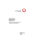
INA Front Panel
The INA module (Figure 1-1) provides the following ports and LED indicators.
DS-1 Status LEDs. The red, green, and yellow LEDs indicate the status of the T1/PRI
line connected to the module. See “T1/PRI LEDs” on page 3-4.
C1 Serial Port. This RJ-45 connector is used to connect the INA module to the
MERLIN MAGIX system control unit and allows an up to 2400-baud dial-up connection
to the INA module’s command line interface. See “Connect a Serial Passthrough Cable”
on page 3-1.
1-2
INA Module Installation and Configuration Guide
INA Front Panel
Figure 1-1
INA Module Front Panel
DS-1 status LEDs
C1 serial port
DIP switches
system LED
console port (C0)
network activity LED
Ethernet port (Ether 0)
Ethernet link LED
Reboot button
T1/PRI port
DS-1 test jacks
1210-001
DIP Switches. DIP switch 1 controls the configuration of serial port C0. DIP switch 2
controls ComOS boot behavior. See “Set DIP Switches” on page 3-2.
System LED. This LED indicates the status of the routing hardware and the ComOS.
One blink every 5 seconds indicates normal operation. See “System LED” on page 3-5.
C0 Serial Port. This RJ-45 connector is used to connect a PC or terminal to act as a
console. The console is used to access the ComOS command line interface. See “Connect
a Console (Optional)” on page 3-3.
Network Activity LED. This amber LED blinks to indicate network traffic. See
“Ethernet LEDs” on page 3-6.
INA Module
1-3
Installation and Configuration Steps
Ethernet Port. This RJ-45 connector provides a 10BaseT Ethernet connection. See
“Connect an Ethernet Cable” on page 3-4.
Ethernet Link LED. This green LED indicates link integrity to a 10BaseT hub. See
“Ethernet LEDs” on page 3-6.
Reboot Button. This button resets the router hardware and reboots ComOS. It has no
effect on MERLIN MAGIX voice operation. You will need a thin object such as a
straightened paper click to activate this recessed switch.
T1/PRI Connection. This RJ-45 connector connects the T1/PRI line. See “Connect a
T1/PRI Cable” on page 3-3.
DS-1 Test Jacks. There are three pairs of jacks for DS-1 troubleshooting. See “Using
the DS-1 Test Jacks” on page A-5.
Installation and Configuration Steps
1. Collect information about your T1 or PRI line.
See “T1/PRI Provisioning” on page 2-1 for a preview of the values you need.
2. Collect information about the network and routing configuration.
See “Network Settings” on page 2-2 for a preview of the values you need.
3. Install the INA module in the MERLIN MAGIX system.
See “Install the INA Module in a Carrier” on page 3-1.
4. Configure the T1 or PRI line using the MERLIN MAGIX console.
See “Set Up T1/PRI on the MERLIN MAGIX” on page 2-1.
5. Assign data channels to the router using the MERLIN MAGIX console.
See “Assign T1/PRI Channels” on page 2-2.
6. Connect the INA module front panel cables.
See “Connect Cables” on page 3-1.
7. Configure the INA module.
See one of the following:
1-4
–
“Using the INAWizard” on page 4-1.
–
“Using the Command Line Interface” on page 5-1.
–
“Using PMVision” on page 6-1.
INA Module Installation and Configuration Guide
Getting Ready for Configuration
2
To properly configure your INA module, you must gather all the technical information
needed. You must also assign T1/PRI channels using the MERLIN MAGIX administration
console before using the INA module.
Before starting the installation of your module, be sure that you have all needed
information from the following categories:
•
“T1/PRI Provisioning” on page 2-1
•
“Network Settings” on page 2-2
T1/PRI Provisioning
Table 2-1 illustrates the T1/PRI information needed to set up the data networking
capabilities of the INA module. Make sure that you have obtained this information from
your telco provider before beginning the configuration process. See Appendix C,
“MERLIN MAGIX Administration” for more information.
Table 2-1
Basic T1/PRI Provisioning Information.
Setting
Notes
Example
DSU channel selection
DSU Channel Selection is
used to assign data
channels to the INA
module. The number of
channels can range from
1 to 24.
Channel 20, 21, 22, 23
Suppression
Bipolar 8-zero
substitution (B8ZS) zero
code suppression must
be used in all applications
of the INA module. For
PRI configurations, only
B8ZS zero code
suppression is supported.
B8ZS
Activate or Deactivate
the CSU
The INA module supports
an internal CSU.
Activate
Set Up T1/PRI on the MERLIN MAGIX
Table 2-1 lists only the T1/PRI settings that are related to the data networking
capabilities of the INA module. Additional settings are required to fully configure the
INA module to support voice services. Examples include B channel group assignments
2-1
Network Settings
for PRI configurations and channel signaling types for T1 configurations. You plan for
and implement these additional settings as you do for a 100D module. See the System
Programming manual (555-710-111).
Assign T1/PRI Channels
The INA module can accommodate up to 23 PRI channels or 24 T1 channels. When the
module is first installed, no channels are assigned to the router.
For PRI configurations, you can assign a channel to the router only if the channel is not
used in a B channel group or a line pool on the switch. For T1 configurations, you can
assign a channel to the router only if the channel is set to Unequipped from a switch
perspective. You determine these channel settings as you do for a 100D module. See the
System Programming manual (555-710-111) for more information.
To assign the desired data channels to the router:
1. Use the following sequence on your MERLIN MAGIX system programming
console:
Menu:
SysProg→Start→LinesTrunks→More→More→CSU/DSU→Slot#→Enter→ChannelSel→
Channel#→Enter
2. Repeat the sequence until all your T1/PRI data channels are assigned.
3. Reboot the router so that it recognizes the change in channel assignments.
You can enter the reboot command at the command line interface, or press the
reboot button on the INA module.
Network Settings
Table 2-2 lists the basic network settings needed to configure the INA module. These are
listed in the order requested by the INAWizard. See the following for more information:
•
For INAWizard configuration, see the INAWizard online help.
•
For command line interface configuration, see Chapter 5, “Using the Command Line
Interface,” and the PortMaster Command Line Reference.
•
For PMVision configuration, see Chapter 6, “Using PMVision.”
WAN Port. After the T1/PRI data channels are assigned to the router, all data channels
are configured as one wide area network (WAN) port by ComOS. If your data channels
are used to form multiple WAN ports, you must set up additional WAN ports.
Additional WAN Ports. You can set up these ports after completing the initial
configuration. Use the command line interface or PMVision to set them up. The
INAWizard cannot be used to set up these additional ports. See one of the following
sections for additional configuration instructions:
•
2-2
See “Set Up Additional WAN Ports” on page 5-6.
INA Module Installation and Configuration Guide
Network Settings
•
See “Set Up Additional WAN Ports” on page 6-7.
Table 2-2
Basic Network Configuration Settings for the INA Module
Settings
Notes
Example
Ether0 address
IP address of the Ether0 port on the
INA module.
192.198.32.2
Ether0 netmask
255.255.255.0
System name
Optional.
Mysystem
First data channel number
assigned to the router
The data channel number determines
the WAN port number, which is 1 (one)
less that the data channel number. For
example, if the first data channel
number is 16, all subsequent channels
are assigned to port W15.
16
Default gateway
192.198.32.1
Name service type
Optional. Select the Domain Name
System (DNS) or Network Information
Service (NIS).
DNS
Name server address
Optional.
192.12.35.1
WAN port address
192.198.32.40
Remote router address
172.12.32.2
Remote router netmask
255.255.255.240
Channel rate
This value is not handled by the
INAWizard. Use the command line
interface or PMVision to set this value.
The default speed is 64Kbps. Almost all
installations use this default value.
56k or 64k
Protocol
Point-to-Point Protocol (PPP) or Frame
Relay.
Frame
Data link connection identifier
(DLCI) list source
For Frame Relay connections only.
Select Local Management Interface
(LMI) or Annex-D, and/or manually
enter a DLCI list.
LMI
DLCI keepalive value
For Frame Relay connections only.
Change the 10-second default, if
necessary, to match the value on the
Frame Relay switch. Contact your telco
for more information.
20
Getting Ready for Configuration
2-3
Network Settings
Table 2-2
Basic Network Configuration Settings for the INA Module (Continued)
Settings
Notes
Example
DLCI list
For Frame Relay connections for which
you manually enter a list. Enter each
DLCI number (1 to 1023), a colon (:),
and the IP address of the router
represented by the DLCI.
16:172.26.131.37
Dynamic Host Connection
Protocol (DHCP) server
address
If you use DHCP. Defaults to Ether0.
192.198.32.17
DHCP lease time
For DHCP dynamically assigned IP
addresses. Enter hours and/or minutes.
A 0 (zero) indicates an infinite time.
8 hours
DHCP static binding IP
address(es) and corresponding
media access control (MAC)
address(es)
For DHCP statically assigned IP
addresses. Enter each IP address and
the 12-digit hexadecimal MAC address
of the host to which it is assigned.
192.198.32.33
DHCP address pool start
address
For DHCP dynamically assigned IP
addresses. Enter one address or the first
in each address range.
192.198.32.65
DHCP address pool end
address
Enter the last address in the range.
192.198.32.127
Network address translator
(NAT) secure address and
corresponding nonsecure
address
If you use NAT static maps. Enter each
secure internal (private) IP address and
the nonsecure external (global) IP
address to which you want it mapped.
192.198.32.22
NAT base IP address
For a NAT dynamic address pool. Enter
one nonsecure external (global) IP
address or the first address in a range.
192.198.32.2
NAT pool size
For a NAT address pool range. Enter a
number of IP addresses up to 64.
64
2-4
00:c0:d5:d4:da:2c
172.18.1.1
INA Module Installation and Configuration Guide
Installing the INA Module
3
This chapter describes the steps needed to physically install and power up the INA
MERLIN MAGIX system. The following topics are discussed.
•
“Install the INA Module in a Carrier” on page 3-1
•
“Connect Cables” on page 3-1
•
“Observe LED Behavior” on page 3-4
Install the INA Module in a Carrier
Install the module in the MERLIN MAGIX carrier according to the directions found in
Chapter 2 of the MERLIN MAGIX Integrated System, Installation, SPM, and Maintenance and
Troubleshooting Supplement (555-661-140).
Turn on the MERLIN MAGIX system. Ensure that the system LED on the module’s front
panel blinks off once every 5 seconds. (See “System LED” on page 3-5.) This behavior
indicates that the module is properly operating and that ComOS has fully booted up. It
may take up to 2 minutes for the INA module to reach this state after the power is
turned on.
Connect Cables
The necessary cables must be connected to the INA module before you can proceed with
the rest of the installation and configuration.
Connect a Serial Passthrough Cable
Connect the supplied straight-through RJ-45 cable between the C1 port (Figure 3-1) on
the INA module and the administration port (labeled ADMIN) on the MERLIN MAGIX
processor module. This cable allows the user to connect to the INA command line
interface by dialing in to the internal modem in the MERLIN MAGIX processor module.
3-1
Connect Cables
Figure 3-1
C1 Serial Passthrough Port
T
O
A
D
M
I
N
C1 serial port
1210-009
Set DIP Switches
The DIP switches (Figure 3-2) must be set to the correct positions for the INA module to
operate properly.
1. Set DIP switch 1 to the right.
Figure 3-2
DIP Switches
DIP switch 1
DIP switch 2
C
O
N
S
O
L
E
DIP switch
1210-002
When DIP switch 1 is set to the right and the INA module is turned on, the console
port is set to 9600bps, 8 data bits, 1 stop bit, no parity, and no flow control. This is
the default setting and is used for connecting the C0 port to a console.
When DIP switch 1 is set to the left, the port settings can be controlled by ComOS.
Use this setting for an external modem that is set up to provide access to the
command line interface, for example.
Note – When you change the position of a DIP switch, you must restart the INA
module for the change to take effect. To reboot, press the recessed reboot button on the
front panel of the module. Pushing this button reboots the router software only and
does not affect voice services.
2. Set DIP switch 2 to the left.
3-2
INA Module Installation and Configuration Guide
Connect Cables
When DIP switch 2 is set to the left (Figure 3-2), and the INA module is turned on,
the INA module boots (loads the ComOS software) from the internal nonvolatile
RAM. This is the default setting for the module.
When DIP switch 2 is set to the right, and the INA module is turned on, the module
boots from an external BOOTP and TFTP server. Use this setting only when serious
hardware or software problems have occurred. You should only use this DIP switch
setting under the direction of Lucent technical support personnel.
Connect a Console (Optional)
You can connect a PC or terminal to the INA module’s console port (Figure 3-3) to
access the command line interface of ComOS.
Figure 3-3
Console Port Connection
Follow these instructions to connect a PC or terminal:
1. If necessary, ensure that your PC or terminal has the same settings as the
console port on the INA module.
The settings are 9600 baud, 8 data bits, 1 stop bit, no parity, and no flow control.
2. Connect a console cable to the C0 port of your INA module and PC or
terminal (Figure 3-3).
See “Console Cable” on page B-1.
3. Reboot the INA module by pressing the recessed reboot button. Verify that
the login prompt appears.
Connect a T1/PRI Cable
Use a category 5 twisted pair cable, as specified by the EIA/TIA-568-B wiring standard,
with an RJ-48C connector to connect to the T1/PRI line (Figure 3-4). See “T1/PRI
Cable” on page B-2 for more information.
Installing the INA Module
3-3
Observe LED Behavior
Figure 3-4
T1/PRI Connection
D
S
1
T1/PRI port
M
O
N
M
O
N
1210-003
Connect an Ethernet Cable
Use a category 5 twisted pair cable, as specified by the EIA/TIA-568-B wiring standard,
with an RJ-48C connector to connect the INA Ethernet connector (Figure 3-5) to the
nearest network hub. See “Ethernet Interface” on page B-2 for more information.
Figure 3-5
Ether0 Connection
E
T
H
E
R
N
E
T
Ethernet port (Ether 0)
1210-004
Observe LED Behavior
Check the T1/PRI, system, and Ethernet LEDs to verify that the installed INA module is
operating properly.
T1/PRI LEDs
These LEDs (Figure 3-6) indicate the status of the T1/PRI line and operate in the same
way as on a 100D module. Make sure they indicate that the T1/PRI line is operating
properly.
3-4
INA Module Installation and Configuration Guide
Observe LED Behavior
Figure 3-6
T1/PRI (DS-1) LEDs
Red
DSI status
Green
Amber
T
O
A
D
M
I
N
1210-005
•
Red illuminated indicates that there is an error condition on the line or that the INA
module is in the standby mode. When in standby mode, the module is not
operational for T1/PRI services. This LED stays illuminated for approximately 15 to
30 seconds when an active line is first connected.
•
Green illuminated indicates that the INA module is in test mode.
•
Amber illuminated indicates that one or more voice calls are currently active on the
T1/PRI interface.
System LED
This LED (Figure 3-7) operates as follows:
Figure 3-7
System LED
System LED
C
O
N
S
O
L
E
1210-008
•
During the initial hardware self-test the LED stays unlit.
•
When the ComOS starts to boot up, the LED lights and remains on.
•
When the system is fully operational, the LED remains on, blinking off once every 5
seconds.
Installing the INA Module
3-5
Observe LED Behavior
After the module has been powered up and loading is complete, make sure that the LED
is blinking off once every 5 seconds. The INA module takes about 20 seconds to reach
this state.
Ethernet LEDs
These LEDs (Figure 3-8) show the status of the Ethernet connection to the INA module.
Figure 3-8
Ethernet LEDs
network activity LED
Ethernet Link LED
E
T
H
E
R
N
E
T
Amber
Green
1210-006
3-6
•
The green link LED is on when the module has link integrity to a 10BaseT hub,
switch, or router. Make sure that this LED lights when a cable has been connected
between the module and an Ethernet hub. If the LED does not light, check the cable
itself and the network connections.
•
The amber network activity led blinks to indicate Ethernet traffic. During heavy
traffic, this LED might appear solid due to its rapid blinking. Depending on your
network, you might not necessarily see much traffic.
INA Module Installation and Configuration Guide
Using the INAWizard
4
The INAWizard program provides basic configuration settings for the INA module. The
wizard uses a graphical user interface (GUI) to guide you step by step through the
configuration process.
The program runs on platforms that use Microsoft Windows 95, Windows 98, or
Windows NT 4.0 and later. A platform with a 486/DX-or-faster processor with 32 MB of
RAM minimum is required. A processor with 48 megabytes RAM is recommended.
The INAWizard performs the initial configuration for new modules, including setting the
IP address for the module’s Ethernet port. The wizard can also be used to reconfigure
modules that have already been set up.
This chapter discusses the following topics:
•
“Install the Wizard” on page 4-1
•
“Connect the Workstation to the INA Module” on page 4-1
•
“Run the Wizard” on page 4-2
Install the Wizard
Install the INAWizard by running the program inawizard_install.exe. The installation
program can be found on the CD-ROM included with this guide. Follow the instructions
in the resulting dialog boxes to complete the installation. Lucent recommends using the
Java runtime engine that comes with the installation package, rather than any existing
copy.
Connect the Workstation to the INA Module
For the wizard to work, an Ethernet connection between the workstation running the
wizard and the module must exist. You can usually make the connection through your
network, but you can use a free standing workstation and a crossover Ethernet cable
instead.
Over a LAN
If the module is being configured for the first time and does not have an Ethernet
address configured, the workstation running the INAWizard and the INA module itself
must be on the same subnet. The wizard automatically identifies the INA module and
sets the Ether0 address.
If the workstation is not on the same subnet, then the initial Ethernet configuration for
the module must be set through a console connection and the command line interface.
See “Connect a Console (Optional)” on page 3-3 and “Set the Ether0 Network
Address” on page 5-3.
4-1
Using the Command Line Interface
5
The ComOS commands can be used to configure the INA module directly through the
ComOS command line interface. You access the command line interface through the
console port C0 using a terminal or PC running a terminal emulator. Once the module
has been connected to a network, the best way to access the command line interface is
through a Telnet session from a network workstation.
This chapter shows the basic ComOS commands that are used to configure the INA
module. Further details can be found in the PortMaster Command Line Reference and the
PortMaster Configuration Guide.
The following configuration steps are discussed:
•
“Connect a Console” on page 5-1
•
“Log In” on page 5-2
•
“Set the Administrative Password” on page 5-2
•
“Set the Ether0 Network Address” on page 5-3
•
“Set the System Name” on page 5-4
•
“Set the Default Route Gateway” on page 5-4
•
“Use Name Resolution (Optional)” on page 5-4
•
“Configure the WAN Port” on page 5-5
Before configuring the INA module with the command line interface, make sure you
have done the following:
•
Assigned T1/PRI channels to the INA module. See “Assign T1/PRI Channels” on
page 2-2.)
•
Collected all the information needed for your network. (See “Network Settings” on
page 2-2.)
Connect a Console
There are three ways to establish a console session. You can use the console port, a
Telnet session or use the MERLIN MAGIX internal modem and the WinSPM
passthrough option.
Using the C0 Console Port
You can connect to the console port with a terminal or a PC workstation running a
terminal emulation program. See “Connect a Console (Optional)” on page 3-3 for more
details.
5-1
Log In
Using a Telnet Session
Once the INA module has been connected to a network and an Ethernet address has
been assigned, Telnet is the best way to establish a console session.
1. Run a Telnet application from a network connected workstation.
2. Select the connect function, and enter the IP address assigned to the INA
module’s Ethernet port.
3. Press Enter if needed.
A login prompt appears.
Using the Passthrough Serial Connection
1. Make sure that the serial passthrough cable has been connected to the INA
module and the MERLN MAGIX processor module.
See “Connect a Serial Passthrough Cable” on page 3-1.
2. Use the MERLIN MAGIX WinSPM application on a PC workstation with a
modem to dial up a connection to the MERLN MAGIX processor module.
Connect to *10 to access the modem.
3. Enter your MERLIN MAGIX system administration password and select
the WinSPM Passthrough option.
4. Press Enter to receive a login prompt to the command line interface of the
router.
Log In
Follow these steps to log in to the INA module:
1. At the login prompt, type !root and press Enter.
2. At the password prompt, press Enter—no password is needed for a
first-time installation.
login: !root
Password:
Command>
Set the Administrative Password
The password is an ASCII-printable string of up to 16 characters used to access the INA
module administrative features. Only a person with administrative access can change
this password.
Enter the following commands to set the password:
5-2
INA Module Installation and Configuration Guide
Set the Ether0 Network Address
Command> set password [Password]
Command> save all
!
Caution – Change the administrative password each time you give it to somone outside
the organization for servicing.
Set the Ether0 Network Address
You can set an IP and IPX address on the INA module. Both IP and IPX routing
protocols are enabled by default. Information on IPX settings can be found in the
PortMaster Configuration Guide and the PortMaster Command Line Reference.
Set the IP Address and Netmask
The IP address identifies the port for IP Ethernet traffic. The default netmask (subnet
mask) is 255.255.255.0. If your network is divided into subnets, enter the netmask that
identifies how your network addresses are divided between the network portion and the
host portion.
Use the following commands to set the IP address and netmask:
Command> set ether0 address Ipaddress
Command> set ether0 netmask Ipmask
Command> save all
Set the Broadcast Address
The broadcast address, constructed from the IP address and netmask of a specified
Ethernet interface, is used by RIP to send information to other hosts on a local Ethernet
network.
When you set a broadcast address for the Ethernet port on the INA module, all other
hosts on the local Ethernet network, must be set to the same broadcast address.
Use these commands to set the broadcast address:
Command> set ether0 broadcast high|low
Command> save all
high—Use when the host part of the binary address is all 1s (ones)—such as
192.168.1.255. This is the most often used setting.
low—Use when the host part of the binary address is all 0s (zeros)—such as
192.168.1.0. This is the default setting.
Using the Command Line Interface
5-3
Set the System Name
Set the System Name
The system name identifies the INA module for Simple Network Management Protocol
(SNMP) queries, IPX protocol routing, and Challenge Handshake Authentication
Protocol (CHAP) authentication.
Use these commands to set the system name:
Command> set sysname String
Command> save all
The system name can have up to 16 characters. When the system name is set, it replaces
the word Command in the prompt.
Set the Default Route Gateway
The default gateway address is the destination address to which the INA module sends
the packet when its
5-4
INA Module Installation and Configuration Guide
Configure the WAN Port
Set the Name Service
The INA module supports either the NIS or the DNS. See the PortMaster Configuration
Guide for more information on name services.
Use these commands to set the name service:
Command> set namesvc dns|nis
Command> save all
Once the name service is set, you must set the address of your NIS or DNS name server
and enter the domain name of your network.
Set the Name Server
The INA module supports RFC 1877, which allows remote hosts also supporting
RFC 1877 to learn the name of a server through PPP negotiation. You must provide the
IP address of the name server if you use a name service.
Use the following command to set the name server:
Command> set nameserver Ipaddress
Command> save all
Note – You can disable the use of a name service by setting the name server’s IP address
to 0.0.0.0.
Set the Domain Name
The domain name is used for hostname resolution. If you are using DNS or NIS, you
must set a domain name for your network.
Command> set domain String
Configure the WAN Port
ComOS automatically creates a WAN port that makes the high-speed dedicated
connection to the INA module. For example, if four PRI channels numbered 5, 6, 7, 8
have been assigned to the INA module, ComOS creates WAN port W4. With a data
capacity of 4 x 64Kbps or 256Kbps.
The WAN port number assigned by ComOS is based on the lowest channel number used
by the channel group minus one. For example, if T1/PRI channels 12, 13, 14, and 15 are
assigned to the INA module, port W11 is assigned to the group.
All data channels assigned to the INA module are initially placed in channel group 1. If
necessary you can configure the channel rate for this channel group.
More than one WAN port can be configured if different groups of T1/PRI channels serve
more then one destination. Additional WAN ports must be separately configured with IP
address, netmask, protocol, channel speed, and any other desired parameters. See “Set
Up Additional WAN Ports” on page 5-6.
Using the Command Line Interface
5-5
Configure the WAN Port
Note – Be sure to reset the WAN port or reboot the router after making changes to the
WAN port configuration. To reboot, enter the reboot command or press the reboot
button on the INA module.
Set the Channel Rate
Almost all data channels have a channel rate of 64Kbs, the default value assigned by
ComOS. However, if the channel rate is 56kbs, you must set the channel rate to that
value.
Cgroup is the defined channel group number. ComOS initially assigns all INA module
data channels to group 1. If you set up additional WAN ports, you must issue this
command for each of the channel groups you have set up.
Use the following commands to set the channel rate:
Command> set line0 group Cgroup 56K|64k
Command> save all
Set Up Additional WAN Ports
To set up additional WAN ports use the following commands:
Command> set line0 group Cgroup channels Channel-list
Command> save all
For example, suppose you had a PRI line with channels 1, 2, 3, and 4 assigned to your
ISP and channels 9 and 10 assigned to a connection to a branch office. Initially, channels
1, 2, 3, 4, 9, and 10 are all assigned to W0 by ComOS. To create a new WAN port, you
must enter the following commands:
Command> set line0 group 2 channels 9 10
Command> save all
Command> reboot
As a result, WAN port W0 is assigned to channels 1, 2, 3, and 4 and WAN port W8 is
assigned to channels 9 and 10.
You must then configure W8 with the desired protocol, IP address, netmask, and related
settings. Be sure to set the correct channel rate for the new group, if necessary, with the
set line0 command.
Set the Port IP Address (Optional)
You can set the local IP address of the W0 port to create an interface with a IP address.
You can use any IP address. If you set the local address of the WAN port to 0.0.0.0 for
PPP, the INA module uses the Ether0 address for the end of the serial link. If you set the
WAN port address to 0.0.0.0 for a Frame Relay connection, the port is disabled.
Use the following commands to set the IP address:
5-6
INA Module Installation and Configuration Guide
Configure the WAN Port
Command> set W1 address Ipaddress
Command> save all
Set the Destination IP Address
The destination IP address is the IP address or hostname of the machine on the other
end of the connection. The destination IP address can also be set to 255.255.255.255 for
PPP users. This setting allows the INA module to learn the IP address of the system on
the other end of the connection using PPP IPCP address negotiation.
Do not set a destination IP address for Frame Relay connections. Instead, use a data link
connection identifier (DLCI) list to link IP addresses to DLCIs, or use the Local
Management Interface (LMI) or Annex-D status updates and Inverse ARP to discover
Frame Relay addresses dynamically. See the PortMaster Configuration Guide for more
information.
Use the following commands to set the destination IP address:
Command> set W1 destination Ipaddress [Ipmask]
Command> save all
Set the Netmask
The default netmask is 255.255.255.0. If the remote network has been divided into
subnets, enter the netmask that identifies how the remote network addresses are
divided between the network portion and the host portion. The value of Ipmask is
dependent upon the size of the IP subnet of which the IP address is a member.
Use the following commands to set the netmask:
Command> set W1 netmask Ipmask
Command> save all
Set the Transport Protocol
The transport protocol can be set to either PPP or Frame Relay. If Frame Relay is used,
additional Frame Relay settings must be configured. See the PortMaster Configuration
Guide for more information.
Use these commands to set the transport protocol:
Command> set W1 protocol ppp|frame
Command> save all
Command> reboot
Apply Filters to the WAN Port (Optional)
Filters can be used to provide elementary firewall protection for your WAN port. For
information on input and output filters, see the PortMaster Configuration Guide.
Using the Command Line Interface
5-7
Configure the WAN Port
5-8
INA Module Installation and Configuration Guide
Using PMVision
6
PMVision is a Java-based program with a graphical user interface (GUI) that can be used
to monitor and configure the INA module. Information about using PMVision on other
platforms can be found in the PMVision User’s Guide, which describes the capabilities of
PMVision in more detail.
PMVision runs on platforms that use Microsoft Windows 95, Windows 98, or NT 4.0 and
later. A platform with a 486/DX or faster processor with 32 MB RAM minimum is
required. A processor with 48 megabytes RAM is recommended.
This chapter briefly describes how to use PMVision to configure a INA module. Consult
the PMVision User’s Guide for information on using other PMVision functions. Topics
covered include:
•
“Install PMVision” on page 6-1
•
“Connect the Workstation to the INA Module” on page 6-1
•
“Run PMVision” on page 6-2
•
“Communicate with the INA Module” on page 6-3
•
“Selecting PMVision Functions” on page 6-4
Install PMVision
To install PMVision on a Windows 95, Windows 98 or NT 4.0 platform, run the
pmvision_install.exe program found on the INA software CD. Follow the instructions
provided by the program.
Connect the Workstation to the INA Module
For PMVision to communicate to the module, an Ethernet connection between the
workstation and the module must exist. You can usually make the connection through
your network. A free standing workstation and a crossover Ethernet cable can be used
instead.
Over a LAN
The Ethernet address for the INA module must be set before you can use PMVision. If
the INAWizard has been already been used to configure the module, then the Ether0
address is set. The Ether0 address can also be set through a console connection and the
command line interface. See “Connect a Console (Optional)” on page 3-3 and “Set the
Ether0 Network Address” on page 5-3.
6-1
Run PMVision
Using a Crossover Cable
An independent laptop or desktop workstation equipped with a network interface card
can be used to run PMVison. Connect an Ethernet crossover cable between the Ethernet
connection on the workstation and the Ethernet port on the INA module. (See
“Crossover Cable” on page B-3.)
Before proceeding, determine the Ethernet address that the INA module has been set to.
Set the workstation’s IP address to an address on the same subnet as the module’s
Ether0 address. An easy way to do so is to choose an address one number above or
below the module’s address.
Run PMVision
Before configuring the INA module with PMVISION, make sure you have done the
following:
•
Assign T1/PRI channels to the INA module. See “Assign T1/PRI Channels” on
page 2-2.)
•
Collect all the information needed for your network. (See “Network Settings” on
page 2-2.)
To start PMVision, select the PMVision icon from the Lucent folder in your Start →
Programs menu. The main PMVision screen appears (Figure 6-1).
6-2
INA Module Installation and Configuration Guide
Communicate with the INA Module
Figure 6-1
PMVision Main Screen
menu bar
connection panel
control tree
panel
main panel
status bar
help bar
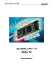
Communicate with the INA Module
Select Device from the menu bar, and click Connect to establish communications
between PMVision and your INA module. The connection dialog box appears
(Figure 6-2). Enter the IP address or Domain Name System (DNS) name of the INA
module into the device text box. If you have connected to this INA module before, you
can also select the address from the drop-down list box. Complete the dialog by
completing the Username and Password text boxes and clicking Connect.
Using PMVision
6-3
Selecting PMVision Functions
Figure 6-2
Connection Dialog
When the connection has been made, information about the INA module appears in the
connection panel. The INA module information line is highlighted, indicating that the
INA module is active and can be controlled by PMVision. PMVision is now ready to
interact with the INA module.
Selecting PMVision Functions
The control tree panel has a section for controlling the INA module. When using
PMVision for the first time, double-click on INA to expand the tree. You must use the
INA section of the tree for proper operation of all functions. Figure 6-3 shows the
control tree.
Figure 6-3
INA Control Tree
Using Configuration Functions
Double-click Configure to display all of the available configuration functions. Select a
configure function by clicking the desired function name in the control tree. When a
function is selected, the main panel shows either a configuration panel or a
configuration display
Working with Configuration Panels
Configuration panels (Figure 6-4) have Save and Refresh control buttons at the
bottom. Enter or edit the desired data, and click the Save button. A dialog appears to
confirm the data to be changed. If you must reboot the PortMaster to update the data, a
dialog box allows the choice between rebooting now or later.
6-4
INA Module Installation and Configuration Guide
Selecting PMVision Functions
Figure 6-4
Configuration Panel Example
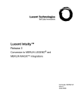
Working with Configuration Displays
Displays (Figure 6-5) have two or more control buttons at the bottom. Click the Add
button to add a new entry and display a configuration panel. Enter the data and click
Save.
You can edit or delete a setting by first selecting the setting to be changed. Clicking Edit
displays a configuration panel. Modify the displayed data and click Save. Clicking
Delete erases the selected settings. Use the Refresh button to refresh the displayed data
and confirm that settings have been updated.
Figure 6-5
Configuration Display Example
Enter Basic Settings
Enter configuration settings by selecting the appropriate functions.
Table 6-1 shows the PMVision functions you would use to enter basic configuration
information. Consult the PMVision User’s Guide or use PMVision online help if more
information is needed.
Table 6-1
Using PMVision
Basic INA Module Configuration Using PMVision
Setting
Select PMVision Function:
Entry
Ether0 address
INA→Configure→Ethernets,
Edit
IP address
6-5
Selecting PMVision Functions
Table 6-1
Basic INA Module Configuration Using PMVision (Continued)
Setting
Select PMVision Function:
Entry
Ether0 netmask
INA→Configure→Ethernets,
Edit
IP netmask
System name
INA→Configure→SNMP
System name
Default gateway
INA→Configure→Global
IP gateway
Name service type
INA→Configure→Global
Name service
Name server address
INA→Configure→Global
Primary name server
WAN port address
INA→Configure→Ports, Sync
ports, Edit
Local IP address
Remote router address
INA→Configure→Ports, Sync
ports, Edit
DestinationIP
address
Remote router
netmask
INA→Configure→Ports, Sync
ports, Edit
Netmask
Channel rate
INA→Configure→Lines,
line0,→Edit→Groups→Edit
Rate, Save
Protocol
INA→Configure→Ports, Sync
ports, Edit
PPP or Frame
DLCI list source
(Frame Relay only)
INA→Configure→Ports, Sync
ports, Edit
Keep Alive
DLCI Keepalive Value
(Frame Relay only)
INA→Configure→Ports, Sync
ports, Edit
Keepalive interval
DLCI list (Frame Relay
only)
6-6
LMI, Annex-D or
manual
DLCI number, IP
address
DHCP server address
INA→Configure→DHCP
Select the checkbox
to enable
DHCP lease time
INA→Configure→DHCP
Lease
DHCP static binding IP
addresses and
corresponding MAC
addresses
INA→Configure→DHCP→
Bindings→Add
IP address, MAC
address
DHCP address pool
start address and end
address
INA→Configure→DHCP
IP pool addresses
INA Module Installation and Configuration Guide
Selecting PMVision Functions
Set Up Additional WAN Ports
If the data channels assigned to the INA module support multiple WAN ports, you must
set up additional WAN ports as follows:
1. Select the INA→Configure→Lines function from the control tree.
2. Select the line0 entry in the main panel, and click the Edit button.
3. Click the Groups button on the line0 panel.
4. Click the Add button.
5. Enter the group number, the list of channels separated by spaces, and the
channel rate, and click OK.
6. Reboot the INA module.
7. Select the INA→Configure→Ports function.
8. Click the Sync Ports button.
9. Select the new WAN port, and click the Edit button.
10. Enter the desired network settings.
The new WAN port will not operate properly unless these settings are correct.
Using the Backup and Restore Functions
Backup and restore functions for the INA module are found under the INA→Maintain
section of the control tree. These functions can backup or restore all or a portion of the
network settings for the INA module.
Lucent strongly recommends that a separate backup be performed before and after any
changes to the INA module routing configuration.
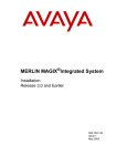
Back Up the INA Module Settings
To create a backup file for the INA module, select INA→Maintain→Back Up. You can
backup the entire configuration or check specific items to backup (See Figure 6-6). After
selecting the backup options, enter or browse to the backup file name and click Backup
to begin the process.
The administrative (!root) password is not backed up or restored by the Maintain
functions.
Using PMVision
6-7
Selecting PMVision Functions
Figure 6-6
PMVision Backup Dialog
Restore the INA Module Settings
To restore the INA module settings captured in a backup file, select
INA→Maintain→Restore. Enter or browse to the backup filename on the Restore
panel (Figure 6-7) and click Restore. The restored values overwrite any values existing
in the INA module. A backup file created with a selective backup overwrites only the
selected configuration values and leaves the others unchanged.
Figure 6-7
6-8
PMVision Restore Dialog
INA Module Installation and Configuration Guide
Troubleshooting
A
This appendix provides the following troubleshooting procedures for the INA module:
•
“Observing LED Behavior” on page A-1
•
“Observing Boot Messages” on page A-2
•
“Using the DS-1 Test Jacks” on page A-5
Additional troubleshooting and maintenance information can also be found in
Appendix C, “MERLIN MAGIX Administration.”
Observing LED Behavior
Table A-1 identifies LED behavior, possible causes of the behavior, and potential
solutions.
For information on contacting Lucent technical support, see “Technical Support” on
page -xv.
Table A-1
Hardware Problems and Solution
LED Behavior
Possible Cause
Solution
System LED does not light.
Power is not present.
Check that the module is correctly
seated in the carrier. Check that the
MERLIN MAGIX system is properly
turned on.
T1/PRI line is connected to
the T1/PRI port and the red
DS-1 status LED stays lit for
more than 30 seconds.
The INA module does not
recognize service from the
telephone company.
Check the T1 cable and modular jack.
If the problem is not resolved, contact
the telephone company.
During startup, the system
LED fails to light or stays
continuously lit.
A hardware problem has
occurred.
Contact Lucent technical support.
Twenty seconds after
booting, the system LED
stays solidly lit or does not
light.
A component might have
loosened during shipping,
or the module is defective.
Contact Lucent technical support.
During operation, the
system LED stays solidly lit
for more than 20 seconds or
does not light.
A hardware problem might
have been caused by an
external device.
If the LED stays solidly lit for more
than 20 seconds or does not light after
you have checked all external cables,
contact Lucent technical support.
A-1
Observing Boot Messages
Table A-1
Hardware Problems and Solution (Continued)
LED Behavior
Possible Cause
Solution
No console login prompt is
displayed.
Terminal settings are
incorrect or a connection or
cable is inoperable.
• Verify terminal settings of 9600
baud, 8 data bits, 1 stop bit, a parity
of none, and software control
(XON/XOFF).
• Verify that DIP switch 1 is set to the
right.
• Verify that you have a working null
modem cable and that it is properly
connected at both ends. For cable
information see “Console Cable” on
page B-1.
Ethernet link LED is not lit
when connected to a
10BaseT Ethernet hub.
There is no link integrity.
Verify that you have a working
10BaseT cable properly connected to
the INA module and to the hub.
Network activity LED is
solidly lit.
Heavy traffic can cause the
network LED to blink so
rapidly that it appears to be
solidly lit.
Verify that the network cables are
correctly installed.
However, if packets cannot
be passed, you might have
an incorrectly cabled
network.
Network activity LED is not
lit.
If the INA module is not
receiving or sending traffic,
the network LED is not lit.
Verify that the network cables are
correctly installed.
An undefined difficulty
occurred at startup, but the
cause cannot be determined
from LED behavior.
Refer to the solution
column.
Try booting in console mode, and
observe the boot messages. See
“Observing Boot Messages” on page
A-2. If the boot messages do not
suggest a solution, record the
information and contact Lucent
technical support.
Observing Boot Messages
If you are having difficulty booting the INA module and are unable to isolate the
problem by observing LED behavior, boot the INA module in console mode and check
the boot messages.
Follow these instructions to check boot messages:
1. Attach a console.
See “Connect a Console (Optional)” on page 3-3.
A-2
INA Module Installation and Configuration Guide
Observing Boot Messages
2. Press the reboot button.
3. Observe the boot messages displayed on the console screen.
Note – Boot messages vary slightly, depending on the version of the PROM and
ComOS.
The following example is from an INA module:
INA PROM 2.33, 8/19/99
Testing System Clock...OK
Sizing System Memory...4MB FPM
CPU 486DX5-133 +Flash
Starting FLASH Boot...
Flash Memory ... Am29F016 4096K
16384 Verifying Checksum..OK
Starting Loader in flash
Testing High Memory ... . 4096K
INA.
Setting up ACC 2188 PCI Controller
Found 15360K PCI Memory at 0x20000000
Testing PCI Memory block 0x20000000-0x20efffff ...Passed
Total of 15360K PCI Memory Ready
block alloc 425 870400
block_alloc: cpu<0> control 0026ddf0 free_count<425>
Flash Memory 0... Am29F016 4096K
Flash type Am29F016 with 4096K of memory in 64 cells and 4032
nodes
Initializing MT8986 TDM Chip ...Ok
INA ComOS V4.1.5b2.
100R HV=01 FBV=00 FAV=11 FAS=01.
Initializing Rockwell Bt8472 HDLC
Found 3 ports....
e_loopback_test: packet buffer at 200d2080
ether0 active ... PCI-Master
stac_hw_init: Initializing STAC hardware, addr = 0x0ffff800
Hardware compression (9711)
Hardware Compression Enabled
Running ComOS...
PortMaster Console login
A-3
Observing Boot Messages
Use Table A-2 to interpret possible diagnostic boot messages.
Table A-2
Interpreting Diagnostic Boot Messages
Field
Possible Message
Explanation
INA PROM
N
Version number of the
installed boot PROM.
Testing System Clock
ERROR
This error indicates a boot
failure. Record all
information to this point
and contact Lucent
technical support.
Sizing System Memory
ERROR at failed
memory address.
This error indicates a boot
failure. Record all
information to this point
and contact Lucent
technical support.
CPU Type
486DX5-133
The type of CPU installed.
Starting FLASH Boot
N/A
N/A
Flash Memory
Am29F016 4096K
Nonvolatile RAM brand
name and size in kilobytes.
16384
16384
Counter for system
memory dynamic RAM
(DRAM) size. If the size
counter freezes, record all
information to this point
and contact Lucent
technical support.
Verifying Load Module Checksum
Invalid Length for
Flash at RAM
address.
This error indicates a boot
failure. Record all
information to this point
and contact Lucent
technical support.
Starting Loader
N/A
N/A
Testing High Memory
ERROR at failed
memory address
This error indicates a boot
failure. Record all
information to this point
and contact Lucent
technical support.
A-4
INA Module Installation and Configuration Guide
Using the DS-1 Test Jacks
Table A-2
Interpreting Diagnostic Boot Messages (Continued)
Field
Possible Message
Explanation
Setting up ACC 2188 PCI Controller
Found 16384K PCI Memory at 0x1ffff000
Testing PCI Memory block 0x200000000x20ffffff ...Passed
Total of 16384K PCI Memory Ready
block alloc 425 870400
block_alloc: cpu<0> control 0028bdb0
free_count<425>
PCI memory has been
correctly set up.
PM3VT/Legend ComOS V4.15.a4.
ComOS version string.
100R HV=01 FBV=00 FAV=11 FAS=01
MERLIN firmware
identification.
Found x ports
3
Number of ports found,
including C0 and C1.
Ether0 active
PCI-Master
Ethernet interface found.
Running ComOS
N/A
If the system becomes
suspended at this point
and does not print the next
message, the configuration
nonvolatile RAM
(NVRAM) has been
corrupted. Refer to the
PortMaster Troubleshooting
Guide for instructions on
nonvolatile RAM recovery.
PortMaster Console login:
N/A
System is up and running.
Using the DS-1 Test Jacks
The six test jacks provide the means to connect external test equipment to the T1/PRI
line. Table A-3 describes the functions of the individual jacks. Figure A-1 illustrates the
test jack locations. Figure A-2 shows the test jack configuration.
A-5
Using the DS-1 Test Jacks
Table A-3
A-6
DS-1 Test Jacks Description
Test Jack Label
Description and Usage
MON In
Monitor In. This jack allows external test equipment to
passively monitor the T1/PRI signal coming from the
network to the INA module. The use of this jack does not
disrupt the T1/PRI signal received by the INA module from
the network.
MON Out
Monitor Out. This jack allows external test equipment to
passively monitor the T1/PRI signal going to the network
from the INA module. The use of this jack does not disrupt
the T1/PRI signal transmitted by the INA module to the
network.
NET In
Network In. An intrusive, break-in jack that allows external
test equipment to inject a T1/PRI signal to the network. The
use of this jack disrupts the T1/PRI signal transmitted by the
INA module to the network.
EQPT Out
Equipment Out. An intrusive, break-in jack that allows
external test equipment to intercept and terminate the
T1/PRI signal coming from the INA module. The use of this
jack disrupts the T1/PRI signal transmitted by the INA
module to the network.
NET Out
Network Out. An intrusive, break-in jack that allows
external test equipment to intercept and terminate the
T1/PRI signal coming from the network. The use of this jack
disrupts the T1/PRI signal received by the INA module from
the network.
EQPT In
Equipment In. An intrusive, break-in jack that allows
external test equipment to inject a T1/PRI signal to the INA
module. The use of this jack disrupts the T1/PRI signal
received by the INA module from the network.
INA Module Installation and Configuration Guide
Using the DS-1 Test Jacks
Figure A-1
DS-1 Test Jack Locations
M
O
N
I
N
M
O
N
O
U
T
N
E
T
I
N
E
Q
P
T
O
U
T
N
E
T
O
U
T
E
Q
P
T
I
N
1210-011
Figure A-2
DS-1 Test Jack Configuration
A-7
Using the DS-1 Test Jacks
A-8
INA Module Installation and Configuration Guide
Cable Specifications
B
This appendix provides cable and pinout specifications.
Cables Specified
•
Console Cable. This null modem cable is used to connect a terminal or PC to the
console port of the INA module.
•
T1/PRI Cable. This cable is used to connect a T1/PRI line to the INA module.
•
Ethernet Interface Cable. This cable is used to connect the Ethernet connector on
the INA module to an Ethernet hub.
•
Crossover Cable. This cable is used to make a simulated network connection
between the INA module’s Ethernet port and a free-standing computer workstation.
Console Cable
Table B-1 shows the cable pinouts for a RJ-45-to-DB-25 null modem cable. The INA
module does not use Data Set Ready (DSR).
Table B-1
Console Cable Pinout
INA Module
Serial Port (C0)
PC or terminal
Serial Port
RJ-45
Name
Definition
Direction
DB-25
(DTE)
Signal
1
RTS
Request to Send
Output
5
CTS
1
2
DTR
Data Terminal Ready
Output
8
3
TXD
Transmit Data
Output
3
DCD
RXD
2
4
GND
Signal Ground
NC
5
GND
Signal Ground
7
GND
6
RXD
Receive Data
Input
2
TXD
7
DCD
Data Carrier Detect
Input
20
DTR
8
CTS
Clear to Send
Input
4
RTS
61
DSR
NC2
Data Set Ready
1. Pins 8 and 6 in the DB-25 connectors are connected internally.
2. Not connected.
B-1
T1/PRI Cable
T1/PRI Cable
Table B-2 shows the pinouts for a category 5 unshielded, ungrounded, twisted pair
cable, as specified by the EIA/TIA-568-B wiring standard, with an RJ-48C connection
Table B-2
T1/E1 RJ-48C Connector Pinout
T1 Port
RJ-48C
Signal
Definition
Direction to or
from the INA
Module
1
RXD (Ring)
Receive Data
Input
2
RXD (Tip)
4
TXD (Ring)
Transmit Data
Output
5
TXD (Tip)
Ethernet Interface
Table B-3 provides specifications for the 10Mbps baseband IEEE 802.3-compatible
Ethernet interface.
Table B-3
Ethernet Interface
Ethernet
Type
Connector
Type
RJ-48C
RJ-48C for 10BaseT
B-2
Cable Type
Category 5
unshielded
twisted pair
Transmission
Distance
Hub distance—328ft (100m) maximum
Repeaters—four maximum
INA Module Installation and Configuration Guide
Crossover Cable
Crossover Cable
This RJ-45 crossover cable is used to connect two (and only two) machines using
10baseT Ethernet without the use of a hub. The cable must be fabricated from category
5 unshielded twisted pair. Table B-4 shows the wiring for this cable.
Table B-4
Crossover Cable Wiring
RJ-45 Connector
RJ-45 Connector
pin 1
pin 3
pin 2
pin 6
pin 3
pin 1
pin 6
pin 2
B-3
Crossover Cable
B-4
INA Module Installation and Configuration Guide
MERLIN MAGIX Administration
C
This appendix describes the MERLIN MAGIX system programming options for the INA
module. The INA module is identified as a 100R module in MERLIN MAGIX
programming and console displays.
The following topics are covered:
•
“INA Module System Programming Summary” on page C-1
•
“INA Module Administration Options” on page C-1
•
“INA Module Maintenance Options” on page C-3
•
“INA Module System Interactions” on page C-7
INA Module System Programming Summary
In general, the INA/100R module supports the same system programming options as the
100D module. Specific exceptions and additions are noted in this appendix. Additions
include the ability to configure and maintain the internal CSU/DSU supported by the
100R module. Exceptions include that only bipolar 8-zero substitution (B8ZS) encoding
is supported when the module is used in PRI mode. For more information on 100D
module programming, see the System Programming Manual (555-710-111).
Note – To avoid corruption of data sent and received by the integrated data router,
Lucent recommends that all T1/PRI lines used with the INA module be provisioned for
B8ZS encoding.
Each 100R module accommodates up to 23 PRI channels or 24 T1 channels. Each
channel can be either used by the MERLIN MAGIX or assigned to the data router.
Channels assigned to the router can be used for Internet access, remote network
connections, and other WAN applications.
Channels on the 100R module provide the same features and capabilities as channels on
a 100D module. For example, the channels on the 100R module can be configured as
robbed-bit channels for T1 applications or can be used in B-channel groups for PRI
applications. Channels on the 100R module count towards system capacities just as
channels on the 100D module do. Channels that are assigned to the router are included
in the count. Therefore, the combined total of 100R and 100D modules in a system
cannot exceed three.
In addition to MERLIN MAGIX system programming, the INA module requires
programming specifically for the router subsystem. (See “Network Settings” on
page 2-2.)
INA Module Administration Options
The INA module introduces two additional administration options: to activate or
deactivate the onboard CSU and DSU channel selection.
C-1
INA Module Administration Options
The rest of the administration options are essentially the same as for the 100D module.
For more information on configuring the 100D module, see System Programming manual
(555-710-111).
Activate or Deactivate the Onboard CSU
The internal CSU on the INA module is activated by default. You can view and change
this setting by using the following sequence on your system programming console:
Menu: SysProg→Start→LinesTrunks→More→More→CSU/DSU→Slot#→Enter→
ActivateCSU
!
Caution – The MERLIN MAGIX is forced into an idle state if the CSU settings are
changed during active voice calls. In this case, the change in CSU status occurs after all
active voice calls have been terminated.
Deactivating the CSU has the following impact on 100R module operation:
•
The 100R board does not respond to network initiated loopback requests.
•
The 100R board does not send T1 performance statistics to the network.
•
The line compensation value used by the 100R board corresponds to the DTE
settings appropriate for a 100D module instead of a CSU. The DTE and CSU values
are summarized in Table C-1
Table C-1
100R Module Line Compensations with a Deactivated CSU
Line Compensation
Setting in MERLIN
MAGIX System
Programming
DTE Line Compensation
When CSU Is
DEACTIVATED
CSU Line Buildout
(LBO) When CSU Is
DEACTIVATED
1
0 to 133 feet
0.0db
2
133 to 266 feet
-7.5db
3
266 to 399 feet
-15db
4
399 to 533 feet
-22.5db
5
533 to 655 feet
-22.5db
DSU Channel Selection
By default, no channels are assigned to the router. DSU channel selection is used to
assign channels to the router. Use the following sequence on your system programming
console to assign channels to the router:
Menu: SysProg→Start→LinesTrunks→More→More→CSU/DSU→Slot#→Enter→
ChannelSel→Channel#→Enter
You must repeat this sequence for each channel to be assigned to the router.
C-2
INA Module Installation and Configuration Guide
INA Module Maintenance Options
Note – For T1 configurations, you can assign a channel to the router only if the channel
is Unequipped from a switch perspective. For PRI configurations, you can assign a
channel to the router only if the channel is not used in a B channel group or a line pool
on the switch.
Note – For the router to recognize a change in channel assignments, you must reboot
the router either from its command line interface or by pressing the reboot button on
the INA module.
You can view a summary of DSU channel assignments by using the following sequence
on your system programming console.
Menu: SysProg→Start→LinesTrunks→More→More→CSU/DSU→
Slot#→Enter→ChannelSel→Inspect
All channels are listed and marked with one of the selections shown in Table C-2:
Table C-2
Inspect DSU Channel Assignments
Selection
Description
R
The channel is assigned to the router.
S
The channel is assigned to the switch.
U
The channel is assigned to neither the router nor the
switch.
Use the following sequence on your system programming console to unassign channels
from the router.
Menu: SysProg→Start→LinesTrunks→More→More→CSU/DSU→
Slot#→Enter→ChannelSel→Channel#→Delete
You must repeat this sequence for each channel to be unassigned from the router.
INA Module Maintenance Options
The 100R module has improved T1/PRI error event reporting and has an expanded set
of demand tests. All 100D module maintenance options are also included.
Error Events
The INA module provides three additional error event counts as well as the ability to
manually clear these error event counts. Included are
•
24-hour event totals
•
Current events
•
Selected interval events
•
Clearing error events
C-3
INA Module Maintenance Options
Note – The additional error event counts are cleared whenever the INA module is reset.
Be sure to view the error events before resetting the module or busying out the module.
From your system programming console, use the following sequence to access the INA
module Error Events screen. Be sure to select the corresponding INA module slot
number.
Menu: Maintenance→Slot→Slot#→Enter→Error Events
The Current Hour and Previous Hour error event screens that are also used on the 100D
module are available on the INA module. Clearing the new error event counts does not
affect the Current Hour and Previous Hour error event counts. Because the Current
Hour and Previous Hour statistics are computed with a different algorithm, Current
Hour and Previous Hour counts do not match the newer counts.
24 Hour Event Totals
The 24-hour total error event screen reports cumulative error statistics spanning the
past 24 hours. The current event totals are not included in this report. From your
system programming console, use the following sequence to access the INA 24 Hr Total
screen. Be sure to select the corresponding INA module slot number.
Menu: Maintenance→Slot→Slot#→Enter→Error Events→24 hr total
This screen provides statistics related to the health of the T1/PRI interface. These
statistics are summarized in Table C-3.
Table C-3
C-4
24-Hour Total Error Line Items
Item
Description
24 Hour Slot xx
xx is the slot currently being reported on.
nn Valid
Intervals
nn is the number of valid historical 15-minute
intervals from the past 24 hours. A valid historical
interval is one for which data has been captured while
the system was running. During a valid interval, data
has not been lost due to a clearing of error events or a
board reset. A board reset can occur during a reset,
busy-out, frigid start, cold start or power outage.
MIS
Misframes.
SLP
Slips.
ES
Errored Seconds.
BS
Bursty errored seconds.
SEC
Severely errored seconds.
FS
Failed seconds.
BPV
Bipolar violations.
INA Module Installation and Configuration Guide
INA Module Maintenance Options
Each error statistic represents the sum of error events from all valid intervals including
the current interval. The message “9999” represents an overflow situation.
You can refresh the 24-hour total screen by pressing →Back and then pressing →24 hr
total again.
Current Events
The Current error event screen reports error statistics for the 15-minute interval that is
currently active. The elapsed minutes line displays the number of minutes that have
elapsed for the current interval. The elapsed minutes display ranges from 0 to 15 and is
rounded to the nearest minute. From your system programming console, use the
following sequence to access the Current screen. Be sure to select the corresponding
INA module slot number.
Menu: Maintenance→Slot→Slot#→Enter→Error Events→Current
The events reported are the same as for the 24 hour event totals screen.
You can refresh the Current screen by pressing →Back and then pressing →Current
again.
Selected Interval Events
The Selected Interval Events screen reports on error statistics for a specific 15-minute
interval from the past 24 hours. Ninety-six 15-minute intervals occur in a 24-hour
period. Interval 1 is the most recent 15 minute interval just before the current interval,
and interval 96 is the oldest interval. From your system programming console, use the
following sequence to select a specific interval from the Selected Interval Events screen.
Be sure to select the corresponding INA module slot number.
Menu: Maintenance→Slot→Slot#→Enter→ErrorEvents→Interval→
Interval#→Enter
Note – Invalid intervals have all zeroes for error data, but no visual indication is given
to show that the interval is not valid. You can, however, compute the total number of
invalid intervals by subtracting the valid interval count on the 24-hour total screen from
96.
Clearing Error Events
The Clear Error Events screen causes error events for all intervals, including the current
interval, to be cleared. From your system programming console, use the following
sequence to access the Clear Error Events screen. Be sure to select the corresponding
INA module slot number.
Menu: Maintenance→Slot→Slot#→Enter→Error Events→Clear
To stop the clear event and retain all error events, press →Back or →Cancel. You will
return to the Error events screen.
C-5
INA Module Maintenance Options
Demand Tests
The INA module board incorporates three new demand tests:
•
Line loopback
•
Payload loopback
•
Bit error rate test (BERT)
Line Loopback Test
The line loopback test loops the T1 signal back towards the network without
regenerating framing and without recalculating a cyclic redundancy test (CRC)
checksum. To perform this test, you must first busy out the INA module. From your
system programming console, use the following sequence to start the line loopback test:
Menu: Maintenance→Slot→Slot#→Enter→Demand test→LineLpbk
After the line loopback test has been started, selecting →Back terminates the test.
Note – During the line loopback test, the INA module transmit clocking is derived from
the signal received by the INA module. The remote end of the T1 connection must be
set up as the clock master for the T1/PRI inrfco v(o)6.5il tilcloo
C-6
INA Module Installation and Configuration Guide
INA Module System Interactions
Table C-4 describes the available BERT test patterns.
Table C-4
BERT Test Patterns
Test Options
Description
→QRSS
Produces a quasi-random test pattern.
→3 in 24
Produces a bit pattern consisting of 3 ones in 24
(1000 1000 1000 0000 0000 0000).
→All zeroes
Produces a test pattern of all zeroes.
→All ones
Produces a test pattern of all ones.
After starting a BERT test, press →Monitor to view the progress of the test. One of the
following results will be displayed.
•
No Synch—Indicates that the BERT test pattern is not being successfully received
back.
•
Sync-Errors—Indicates that the BERT test pattern is being successfully received.
The console displays the number of bit error detected. For overflow situations
“99999” is displayed.
To refresh the display, press →Back, and then select →Monitor. This refreshes the test
results without terminating the test.
Note – During BERT testing, the INA module transmit clocking is derived from the
backplane of the MERLIN MAGIX. The remote end of the T1 connection must be set up
as either the clock slave for the T1/PRI interface, or must provide a line loopback.
INA Module System Interactions
Backup and Restore
Like the 100D module, any programming done on the MERLIN MAGIX for the INA
module can be backed up and restored with the system Personal Computer Memory
Card International Association (PCMCIA) card or by a PC running WinSPM. The new
administration options for the INA module (CSU Activate/Deactivate and DSU Channel
Selection) are included.
Note – Administration data associated with the router is not backed up and restored by
the MERLIN MAGIX backup functions. Router administration data must be backed up
and restored separately by using PMVision (see Chapter 6, “Using PMVision”). The
INAWizard may be used to restore the basic network settings, but is not a true backup.
(See Chapter 4, “Using the INAWizard”.)
Surrogate Operation
The INA module supports surrogate mode programming. The INA module is indicated
on MERLIN MAGIX system programming screens by the label 100R-U.
C-7
INA Module System Interactions
Board Renumbering
The INA module works in the same manner as the 100D module for board
renumbering. Use board renumbering to replace a 100D module with a 100R module,
and vice versa. After the board renumbering, T1/PRI data that had been previously
administered for the replaced module is associated with the new module. The data
channels assigned to the 100R are now be unassigned on the 100D module.
Print Reports
The System Inventory Report is enhanced to include summary information about INA
modules present in the system. This summary information is presented under the
100-RU label.
PCMCIA Flash Memory Card-Based Upgrade Operation
The INA module firmware is upgradeable using the MERLIN MAGIX PCMCIA card.
Note – Performing an upgrade to the INA module firmware using the MERLIN MAGIX
PCMCIA card does not upgrade the INA module router software. Router software is
upgraded separately with the PMVision application. Depending upon the nature of the
upgrade, either a INA module firmware upgrade, or a router software upgrade, or both
might be required.
Other System Interactions
Table C-5 shows system conditions applying to the INA module.
Table C-5
C-8
INA Module System Interactions
Condition
Explanation
Idle Conditions System Forced
Idle
The system might be forced into an idle state
while the module is routing data traffic. When
the system is in the forced idle condition, the
router on the INA module continues to operate
and route data traffic.
Slot Busy-Out
An INA module can be busied out even if the
module is routing data traffic. Busying out the
module disrupts both voice and router services.
Voice and data services are restored when the
module is restored.
INA Module Installation and Configuration Guide
INA Module System Interactions
Table C-5
INA Module System Interactions (Continued)
Condition
Explanation
System Erase
(Frigid Start)
When a frigid start occurs, all MERLIN MAGIX
parameters for the INA module are returned to
default values. Router administration data,
however, is preserved. MERLIN MAGIX
parameters must be reprogrammed after the
frigid start to restore voice and data services. The
router must be rebooted after DSU channel
selection has been performed.
System Restart
(Cold Start)
All programming for the INA module is saved
during a cold start. Voice and router services are
disrupted for the duration of the cold start but
are restored after the cold start.
Warm Start
All the programming for the INA module is saved
during a warm start.
Board
Replacement
You must turn the power off on the MERLIN
MAGIX before replacing an INA module. The
INA module is not hot-swappable.
C-9
INA Module System Interactions
C-10
INA Module Installation and Configuration Guide
Index
Numerics
100D module C-1
operation 2-2
renumbering boards C-8
24-hour event totals C-4
A
activate or deactivate CSU 2-1, C-2
administration options C-1
administrative password 5-2
B
B8ZS encoding 2-1, C-1
backup
INA module settings 6-7
MERLIN MAGIX settings C-7
BERT C-6
bipolar 8-zero substitution. See B8ZS
bit error rate test (BERT) C-6
boards
renumbering C-8
replacement C-9
boot messages
checking A-2
interpreting A-4
boot mode, configuring 3-3
BOOTP 3-3
broadcast address, setting 5-3
C
C0 port
location 1-3
using 5-1
C1 serial port
location 1-2
using for console session 5-2
cables
connecting 3-1
console 3-3, B-1
crossover B-3
Ethernet 3-4, B-2
passthrough 3-1
specifications B-1
T1/PRI 3-3, B-2
caution icon xiv
channel rate, setting 2-3, 5-6, 6-6
channels
assigning 2-2, C-2
setting 5-6
channel service unit. See CSU
code supression, B8ZS 2-1, C-1
cold start C-9
command line interface
description 1-2
using 5-1
configuration
console port 3-2
getting information 2-1
parameters 2-3
steps 1-4
configuration displays, PMVision 6-5
configuration functions, PMVision 6-4
configuration panels, PMVision 6-4
connecting
console 3-3
Ethernet cable 3-4
INAWizard workstation 4-1
PMVision workstation 6-1
serial passthrough cable 3-1
T1/PRI Cable 3-3
console
cable B-1
checking messages A-2
configuring port 3-2
connecting 3-3
console port. See C0 port console session
console session
C1 serial port 5-2
passthrough serial connection 5-2
Telnet 5-2
using C0 port 5-1
contact information
Lucent technical support xv
mailing lists xv
conventions in this guide xiv
crossover cable
Index-1
Index
pinout B-3
PMVision 6-2
CSU
activate or deactivate 2-1, C-2
line buildout C-2
CSU/DSU 1-1
current events C-5
D
data channels
description 1-1
first channel assigned 2-3
unassigning C-3
data link connection identifier. See DLCI settings
data service unit. See DSU
deleting data channels C-3
demand tests C-6
destination address 5-7
DHCP settings 2-4
diagnostic messages A-4
DIP switch
boot mode 3-2
location 1-3
setting 3-2
DLCI settings 2-3, 5-7, 6-6
document advisory xiv
documentation
MERLIN MAGIX xi
PortMaster xiii
document conventions xiv
domain name 5-5
DS-1 LEDs
front panel location 1-2
observing 3-4
DS-1 test jacks
location 1-4, A-7
using A-5
DSU
channel assignments C-3
channel selection 2-1, C-2
Dynamic Host Connection Protocol. See DHCP
settings
E
electrical shock risk ix
error events
24-hour event totals C-4
clearing C-5
Index-2
current events C-5
selected interval C-5
Ethernet
cable B-2
connecting cable 3-4
LEDs 3-6
Ethernet activity LED
location 1-3
observing 3-6
Ethernet interface B-2
location 1-4
specifications B-2
Ethernet link LED
location 1-4
observing 3-6
F
filters, on WAN port 5-7
fire risk ix
Frame Relay. See protocol, WAN port.
frigid start C-9
front panel 1-2
functions, PMVision 6-4
G
gateway 2-3, 5-4, 6-6
H
hostname resolution 5-4
hot-swappability C-9
I
idle conditions C-8
INA module
administration 1-1
administration options C-1
basic settings 2-3, 6-5
board renumbering C-8
command line interface connection 5-1
description 1-1
front panel 1-3
INA wizard connection 4-1
installation 3-1
maintenance options C-3
overview of installation and configuration 14
PMVision connection 6-1
replacement C-9
INA Module Installation and Configuration Guide
Index
system interactions C-7
system programming summary C-1
INAWizard
description 1-2
installation 4-1
operation 4-2
system requirements 4-1
inawizard_install.exe 4-1
INAWizard workstation
connection with crossover cable 4-2
LAN connection 4-1
injury risk ix
installation
INA module 3-1
INAWizard 4-1
PMVision 6-1
steps 1-4
IP address, Ether0
broadcast 5-3
network 2-3, 5-3, 6-5
IP address, W0
destination 2-3, 5-7, 6-6
local 2-3, 5-6, 6-6
IPX 5-3
L
LAN connection
INAWizard 4-1
PMVision 6-1
LEDs
DS-1 3-4
Ethernet 3-6
observing for troubleshooting A-1
system 3-5
T1/PRI 3-4
line loopback test C-6
link LED
location 1-4
observing 3-6
local WAN port address 2-3, 6-6
login 5-2
M
mailing lists, subscribing to xv
maintenance options C-3
MERLIN MAGIX
setup T1/PRI 2-1
software upgrade C-8
MERLIN MAGIX administration
assign channels commands 2-2, C-2
programming summary C-1
messages on the console
checking A-2
interpreting A-4
N
name service 2-3
NAT settings 2-4
netmask
Ether0 2-3, 6-6
W0 6-6
network activity LED
location 1-3
network address
setting 5-3
network address translation. See NAT
network parameters 2-2, 6-5
note icon xiv
O
observe LED behavior 3-4
P
parameters, basic configuration 2-3, 5-3, 6-5
passthrough serial connection
cable 3-1
using 5-2
payload loopback test C-6
PCMCIA upgrade C-8
PMVision
adding WAN ports with 6-7
backup function 6-7
basic settings 6-5
communicating with INA 6-3
configuration displays 6-5
configuration functions 6-4
configuration panels 6-4
connect workstation 6-1
description 1-2
entering settings with 6-5
installation 6-1
LAN connection 6-1
restore function 6-8
running 6-2
selecting functions 6-4
setting WAN ports 6-7
system requirements 6-1
using 6-1
Index-3
Index
Point-to-Point protocol. See protocol, WAN port
PPP. See protocol, WAN port
precautions, safety ix
print reports C-8
protocol, WAN port 2-3, 5-7, 6-6
R
reboot button, location 1-4
removing data channels C-3
renumbering boards C-8
reports C-8
restoring
INA module settings 6-8
MERLIN MAGIX settings C-7
running PMVision 6-2
S
safety instructions ix
selected interval events C-5
serial passthrough
connecting 3-1
using 5-2
set administrative password 5-2
set broadcast address 5-3
set channel rate 5-6
set default route gateway 5-4
set DIP switch 1 to the right. 3-2
set DIP Switches 3-2
set domain 5-5
set Ether0 broadcast 5-3
set Ether0 netmask 5-3
set gateway 5-4
set line0 channels 5-6
set nameserver 5-5
set namesvc 5-5
set system name 5-4
settings
INAWizard 2-3
using PMVision for 6-5
set W1 address 5-7
set W1 destination 5-7
set W1 netmask 5-7
set W1 protocol 5-7
set W1 speed 5-6
slot busy out C-8
SPM. See WinSPM
Index-4
subnet mask 5-3, 5-7
support, technical xiv, xv
surrogate operation C-7
system erase C-9
system interactions C-7, C-8
system LED
location 1-3
observing 3-5
system name 2-3, 5-4, 6-6
system requirements
INAWizard 4-1
PMVision 6-1
system restart C-9
T
T1/PRI
all unequipped 2-2, C-2
assign channels 2-2, C-2
assigning channels 2-2
cable B-2
connector location 1-4
LEDs 3-4
MERLIN setup 2-1
provisioning information 2-1
unequipped 2-2, C-2
tables, configuration 6-5
technical support xv
telnet console session 5-2
test jacks, DS-1
location 1-4, A-7
using A-5
tests
BERT C-6
line loopback C-6
C-6
payload
loopback
training
INA module xv
PortMaster xv
transport protocol. See protocol, WAN port
troubleshooting INA module A-1
U
unassigning data channels C-3
using INAWizard 4-1, 6-1
using WinSPM 5-2
V
voice channels, description 1-1
INA Module Installation and Configuration Guide
Index
W
WAN port
additional 2-2
channel rate 2-3, 5-6
filters 5-7
protocol 5-7
rebooting 5-6
setting 5-5
setting with PMVision 6-7
warm start C-9
warning icon xiv
warranty xv
WinSPM
passthrough option 5-1, 5-2
utility 1-1
wizard. See INAWizard
Index-5