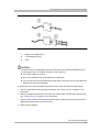
1
MERLIN MAGIX®Integrated System
Installation
Release 3.0 and Earlier
555-730-140
Issue 1
May 2003
Copyright © 2003
Avaya Inc.
All Rights Reserved
Printed in USA
Document 555-730-140
Issue 1
May 2003
Notice
Every effort has been made to ensure that the information in this guide is complete and accurate at the time of
printing. Information, however, is subject to change. See Appendix A, “Customer Support Information,” in Feature
Reference for important information.
Avaya Web Page
The world wide web home page for Avaya is http://www.avaya.com.
Preventing Toll Fraud
Toll Fraud is the unauthorized use of your telecommunications system by an unauthorized party (for example, a
person who is not a corporate employee, agent, subcontractor, or working on your company's behalf). Be aware
that there is a risk of toll fraud associated with your system and that, if toll fraud occurs, it can result in substantial
additional charges for your telecommunications services.
Avaya Fraud Intervention
If you suspect that you are being victimized by toll fraud and you need technical assistance or support, call
Technical Service Center’s Toll Fraud Intervention Hotline at 800 643-2353.
Providing Telecommunications Security
Telecommunications security of voice, data, and/or video communications is the prevention of any type of
intrusion to, that is, either unauthorized or malicious access to or use of, your company's telecommunications
equipment by some party.
Your company's “telecommunications equipment” includes both this Avaya product and any other voice/data/video
equipment that could be accessed via this Avaya product (that is, “networked equipment”).
An “outside party” is anyone who is not a corporate employee, agent, subcontractor, or working on your
company's behalf. Whereas, a “malicious party” is anyone, including someone who may be otherwise authorized,
who accesses your telecommunications equipment with either malicious or mischievous intent.
Such intrusions may be either to/through synchronous (time multiplexed and/or circuit-based) or asynchronous
(character-, message-, or packet-based) equipment or interfaces for reasons of:
• Utilization (of capabilities special to the accessed equipment)
• Theft (such as, of intellectual property, financial assets, or toll-facility access)
• Eavesdropping (privacy invasions to humans)
• Mischief (troubling, but apparently innocuous, tampering)
• Harm (such as harmful tampering, data loss or alteration, regardless of motive or intent)
Be aware that there may be a risk of unauthorized or malicious intrusions associated with your system and/or its
networked equipment. Also realize that, if such an intrusion should occur, it could result in a variety of losses to
your company, including, but not limited to, human/data privacy, intellectual property, material assets, financial
resources, labor costs, and/or legal costs.
Copyright and Legal Notices
Your Responsibility for Your Company's Telecommunications Security
The final responsibility for securing both this system and its networked equipment rests with you - an Avaya
customer's system administrator, your telecommunications peers, and your managers. Base the fulfillment of your
responsibility on acquired knowledge and resources from a variety of sources, including, but not limited to:
• Installation documents
• System administration documents
• Security documents
• Hardware-/software-based security tools
• Shared information between you and your peers
• Telecommunications security experts
To prevent intrusions to your telecommunications equipment, you and your peers should carefully program and
configure your:
• Avaya provided telecommunications system and their interfaces
• Avaya provided software applications, as well as their underlying hardware/software platforms and interfaces
• Any other equipment networked to your Avaya products
Federal Communications Commission Statement
This equipment has been tested and found to comply with the limits for a Class A digital device, pursuant to Part
15 of the FCC Rules. These limits are designed to provide reasonable protection against harmful interference
when the equipment is operated in a commercial environment. This equipment generates, uses, and can radiate
radio frequency energy and, if not installed and used in accordance with the instruction manual, may cause
harmful interference to radio communications. Operation of this equipment in a residential area is likely to cause
harmful interference, in which case the user will be required to correct the interference at their own expense. For
further FCC information, see Appendix A, “Customer Support Information,” in Feature Reference.
Part 68: Network Registration Number. This equipment is registered with the FCC in accordance with Part 68 of
the FCC Rules. See Appendix A, “Customer Support Information, “FCC Notification and Repair” section for
registration numbers and more information regarding Part 68.
Part 68: Answer-Supervision Signaling. Allowing this equipment to be operated in a manner that does not
provide proper answer-supervision signaling is in violation of Part 68 Rules. This equipment returns answersupervision signals to the public switched network when:
• Answered by the called station
• Answered by the attendant
• Routed to a recorded announcement that can be administered by the CPE user
This equipment returns answer-supervision signals on all DID calls forwarded back to the public switched
telephone network. Permissible exceptions are:
• A call is unanswered
• A busy tone is received
• A reorder tone is received
Industry Canada (IC) Interference Information
NOTICE: This equipment meets the applicable Industry Canada Terminal Equipment Technical Specifications.
This is confirmed by the registration number. The abbreviation, IC, before the registration number signifies that
registration was performed based on a Declaration of Conformity indicating that Industry Canada technical
specifications were met. It does not imply that Industry Canada approved the equipment.
Le Présent Appareil Nomérique n’émet pas de bruits radioélectriques dépassant les limites applicables aux
appareils numériques de la class A préscrites dans le reglement sur le brouillage radioélectrique édicté par le
Industrie Canada.
Copyright and Legal Notices
Trademarks
5ESS, AUDIX, CONVERSANT, CentreVu, DEFINITY, Magic On Hold, MERLIN, MERLIN LEGEND, MERLIN
MAGIX, MERLIN Mail, PARTNER, PassageWay, MLX-10, MLX-20L, MLX-28D, MLS-6, MLS-12, MLS-12D, MLS18D, MLS-34D, SYSTIMAX, TransTalk, and Voice Power are registered trademarks and 4ESS, Intuity, and
ProLogix are trademarks of Avaya Inc. in the U.S. and other countries.
Acculink, ACCUNET, MEGACOM, MulitiQuest, MLX-5, MLX-5D, MLX-16DP, MLX-10D, MLX-10DP, and
NetPROTECT are registered trademarks of AT&T.
Microsoft, Windows, Windows NT, and MS-DOS are registered trademarks of Microsoft Corporation.
PSupra, Supra NC, StarSet, and Mirage are registered trademarks of Plantronics, Inc.
UNIX is a registered trademark of UNIX System Laboratories, Inc.
PagePac is a registered trademark and Powermate and Zonemate are trademarks of DRACON, a division of
Harris Corporation.
Okidata is a registered trademark of Okidata Corporation.
Pipeline is a trademark of Ascend Communications, Inc.
Intel and Pentium are registered trademarks of Intel Corporation.
Apple and Macintosh are registered trademarks of Apple Computer, Inc.
IBM is a registered trademark of International Business Machines, Inc.
Novell and NetWare are registered trademarks of Novell Corporation.
CLASS is a servicemark of Bellcore.
Ordering Information
Call:
Avaya Publications Center
Voice 1 800 457-1235
Fax 1 800 457-1764
Write:
GlobalWare Solutions
200 Ward Hill Avenue
Haverhill, MA 01835 USA
Attention: Avaya Account
Management
Email:
[email protected]
Order:
Document No. 555-730-140
Issue 1, May, 2003
International Voice +1 207.866.6701
International Fax +1 207.626.7269
For more information about Avaya documents, refer to the section entitled “Related Documents” in “About This
Guide” in Feature Reference.
Support Telephone Number
In the continental U.S., Avaya provides a toll free customer helpline 24 hours a day. Call the Avaya Customer Care
Center at 1 800 628-2888 or your Avaya authorized dealer if you need assistance when installing, programming,
or using your system. Outside the continental U.S., contact your local Avaya authorized representative.
Warranty
Avaya Inc. provides a limited warranty on this product. Refer to your sales agreement to establish the terms of the
limited warranty. In addition, Avaya’s standard warranty language as well as information regarding support for this
product, while under warranty, is available through the following website: www.avaya.com/support.
Obtaining Products
To learn more about Avaya products and to order products, contact Avaya Direct, the direct-market organization of
Avaya Business Communications Systems. Access their web site at avaya.com/direct or call 800 426-2455.
Installation
IMPORTANT SAFETY INSTRUCTIONS
!
The exclamation point in an equilateral triangle is intended to alert the user to the presence of
important operating and maintenance (servicing) instructions in the literature accompanying the
product.
When installing telephone equipment, always follow basic safety precautions to reduce the risk of fire, electrical
shock, and injury to person, including:
■
■
■
■
■
■
■
■
■
■
■
■
■
■
■
■
■
■
■
Read and understand all instructions.
Follow all warnings and instructions marked on or packed with the product.
Never install telephone wiring during a lightning storm.
Never install a telephone jack in a wet location unless the jack is specifically designed for wet locations.
Never touch uninsulated telephone wires or terminals unless the telephone wiring has been disconnected at
the network interface.
Use caution when installing or modifying telephone lines.
Use only Avaya Inc.-manufactured MERLIN MAGIX Integrated System circuit modules, carrier assemblies,
and power units in the MERLIN MAGIX Integrated System control unit.
Use only Avaya Inc.-recommended/approved MERLIN MAGIX Integrated System accessories.
If equipment connected to the TDL telephone modules (412 LS-ID-TDL and 024 TDL), the MLX telephone
modules (008 MLX, 408 GS/LS-MLX, 408 GS/LS-ID-MLX, and 016 MLX), or the ETR telephone module
(016 ETR) is to be used for in-range out-of-building (IROB) applications, IROB protectors are required.
Do not install this product near water—for example, in a wet basement location.
Do not overload wall outlets, as this can result in the risk of fire or electrical shock.
The MERLIN MAGIX Integrated System is equipped with a 3-wire grounding-type plug with a third
(grounding) pin. This plug will fit only into a grounding-type power outlet. This is a safety feature. If you are
unable to insert the plug into the outlet, contact an electrician to replace the obsolete outlet. Do not defeat
the safety purpose of the grounding plug.
The MERLIN MAGIX Integrated System requires a supplementary ground.
Do not attach the power supply cord to building surfaces. Do not allow anything to rest on the power cord.
Do not locate this product where the cord will be abused by persons walking on it.
Slots and openings in the module housings are provided for ventilation. To protect this equipment from
overheating, do not block these openings.
Never push objects of any kind into this product through module openings or expansion slots, as they may
touch dangerous voltage points or short out parts, which could result in a risk of fire or electrical shock.
Never spill liquid of any kind on this product.
Unplug the product from the wall outlet before cleaning. Use a damp cloth for cleaning. Do not use cleaners
or aerosol cleaners.
Auxiliary equipment includes answering machines, alerts, modems, and fax machines. To connect one of
these devices, you must first have a Multi-Function Module (MFM).
Do not operate telephones if chemical gas leakage is suspected in the area. Use telephones located in
some other safe area to report the trouble.
!
! WARNING:
To eliminate the risk of personal injury due to electrical shock, DO NOT attempt to install or remove an MFM
from your MLX telephone. Opening or removing the module cover of your telephone may expose you to
dangerous voltages.
ONLY an authorized technician or dealer representative shall install, set options, or repair an MFM.
SAVE THESE INSTRUCTIONS
Safety
Installation
Master Table of Contents
Enhancements
Release 3.0 Enhancements (May 2003).........................................................................xi
Release 2.2 Enhancements (June 2002)...................................................................... xiii
Release 2.2 Enhancements (June 2002).......................................................................xv
Release 2.1 Enhancements (November 2001) ........................................................... xvii
Release 2.0 Enhancements (January 2001)................................................................ ixix
Release 2.0 Enhancements
(January 2001)
xx
Release 1.5 Enhancements
(June 1999) ................................................................................................................... xxi
About This Guide
Intended Audience ...................................................................................................... xxvi
How to Use This Guide ............................................................................................... xxvi
Terms and Conventions Used.................................................................................... xxvii
Security ....................................................................................................................... xxix
Related Documents...................................................................................................... xxx
How to Comment on This Guide ................................................................................. xxxi
1
Pre-Installation
Overview ...................................................................................................................... 1-1
Space Requirements.................................................................................................... 1-1
Environmental Requirements....................................................................................... 1-2
Backboard Requirements............................................................................................. 1-3
AC Grounding Requirements ....................................................................................... 1-4
Control Unit Grounding Requirements ........................................................................ 1-8
Unit Load Calculation ................................................................................................. 1-11
2
Installing the Control Unit
Overview ...................................................................................................................... 2-1
Mounting an Empty Basic Carrier ................................................................................ 2-1
Master TOC i
Installation
Mounting a Populated Basic Carrier ............................................................................ 2-3
Mounting Empty Expansion Carriers .......................................................................... 2-7
Mounting Populated Expansion Carriers ..................................................................... 2-9
Installing the Power Supply.......................................................................................... 2-9
Grounding the Control Unit ........................................................................................ 2-11
Installing the Processor............................................................................................. 2-14
Installing the Modules ................................................................................................ 2-15
Removing Modules .................................................................................................... 2-16
Using Tie Trunks ........................................................................................................ 2-18
Labeling the Jacks ..................................................................................................... 2-22
Powering Up the System ........................................................................................... 2-24
Powering Down the System ....................................................................................... 2-24
Installing/Removing the Cover on the Carrier ............................................................ 2-25
3
Installing Telephones and Adjuncts
Overview ...................................................................................................................... 3-1
Assembling MLX Telephones ..................................................................................... 3-4
Assembling 4400 Series Telephones ........................................................................ 3-12
Connecting Telephones to the Control Unit ............................................................... 3-21
Installing Adjuncts ...................................................................................................... 3-27
Installing the DSS4450 for MLX Telephones ............................................................. 3-44
Installing the DSS 450 for 4400 Series Telephones .................................................. 3-49
Installing Multi-Function Modules............................................................................... 3-53
4
Connecting the Control Unit to the Network Interface
Overview ...................................................................................................................... 4-1
Before You Begin ........................................................................................................ 4-2
Common Interfaces and Adapters ............................................................................... 4-2
Network Interface Codes ............................................................................................. 4-3
RJ21X Interface ........................................................................................................... 4-3
RJ11 and RJ14 Interfaces ........................................................................................... 4-8
RJ2GX Interface ........................................................................................................ 4-10
RJ48C/X Interface...................................................................................................... 4-10
Testing Trunks ........................................................................................................... 4-10
ii Master TOC
Master Table of Contents
Labeling Trunks.......................................................................................................... 4-12
Installing the Channel Service Unit ............................................................................ 4-12
5
Installing the PC, CAT or Printer
Connecting a PC to the Control Unit for System Programming or Maintenance ......... 5-1
Connecting a CAT to the Control Unit......................................................................... 5-8
Connecting a Printer to the Control Unit .................................................................... 5-13
6
Data and Video Applications
Overview ...................................................................................................................... 6-1
Analog Data Workstations........................................................................................... 6-2
Digital Data Workstations............................................................................................. 6-6
100DCD Module for T1/PRI Capability ..................................................................... 6-16
100R INA Module for T1/PRI Capability.................................................................... 6-25
Configuring the 100R INA Module ............................................................................. 6-34
Data Communications Software................................................................................. 6-74
Video Communications Software ............................................................................... 6-75
7
Initializing and Testing the System
Initializing the System .................................................................................................. 7-1
Setting the Time and Date ........................................................................................... 7-2
Testing the System ...................................................................................................... 7-2
8
Upgrading the System
Overview ...................................................................................................................... 8-1
Upgrading from MERLIN MAGIX
Release 2.2 or Earlier .................................................................................................. 8-1
Upgrading from a MERLIN LEGEND System ............................................................. 8-2
PCMCIA Upgrade Card.............................................................................................. 8-13
Automatic Conversion of Backup Files ...................................................................... 8-15
Flow Control ............................................................................................................... 8-16
A
Unit Load Calculation
Overview ......................................................................................................................A-1
Configuration Rules for Power Supplies
Master TOC iii
Installation
(assumes a mix of telephone types) ............................................................................A-2
Unit Load Capacity of Power Supplies.........................................................................A-2
Unit Load Rules for Different Modes ............................................................................A-3
Calculation of Unit Loads .............................................................................................A-3
Unit Load Worksheet ...................................................................................................A-5
iv Master TOC
Installation
Master List of Figures
1
Pre-Installation
1-1
1-2
1-3
2
Installing the Control Unit
2-1
2-2
2-3
2-4
2-5
2-6
2-7
2-8
2-9
2-10
2-11
3
AC Grounding Requirements . . . . . . . . . . . . . . . . . . . . . . . . . . . . . . . . . . . . . . 1-5
Measuring the AC Outlet Voltages . . . . . . . . . . . . . . . . . . . . . . . . . . . . . . . . . . 1-7
Configuring Power Surge and Protectors . . . . . . . . . . . . . . . . . . . . . . . . . . . . 1-10
Marking the Basic Carrier Screw Holes . . . . . . . . . . . . . . . . . . . . . . . . . . . . . . 2-2
Mounting the T Brackets . . . . . . . . . . . . . . . . . . . . . . . . . . . . . . . . . . . . . . . . . 2-4
Fastening the Left and Right Brackets on the Carrier . . . . . . . . . . . . . . . . . . . 2-5
Securing the Left and Right Bracket . . . . . . . . . . . . . . . . . . . . . . . . . . . . . . . . 2-6
Connecting the Carriers . . . . . . . . . . . . . . . . . . . . . . . . . . . . . . . . . . . . . . . . . . 2-8
Central Office and AC Grounds . . . . . . . . . . . . . . . . . . . . . . . . . . . . . . . . . . . 2-11
Installing the Processor into the Carrier . . . . . . . . . . . . . . . . . . . . . . . . . . . . . 2-14
Removing a Module . . . . . . . . . . . . . . . . . . . . . . . . . . . . . . . . . . . . . . . . . . . . 2-17
400 E&M Module Sample Dip Switch Settings for Signaling
Types 1C and 5 . . . . . . . . . . . . . . . . . . . . . . . . . . . . . . . . . . . . . . . . . . . . . . . 2-21
Line/Trunk and Telephone Jack Locations on Each Module . . . . . . . . . . . . . 2-23
Installing the Cover for the Carrier . . . . . . . . . . . . . . . . . . . . . . . . . . . . . . . . . 2-25
Installing Telephones and Adjuncts
3-1
3-2
3-3
3-4
3-5
3-6
3-7
3-8
3-9
3-10
3-11
3-12
Adjusting or Removing the Desk Stand . . . . . . . . . . . . . . . . . . . . . . . . . . . . . . 3-5
Connecting the Line Cords . . . . . . . . . . . . . . . . . . . . . . . . . . . . . . . . . . . . . . . . 3-6
Removing the Extension Label . . . . . . . . . . . . . . . . . . . . . . . . . . . . . . . . . . . . 3-7
Labeling the Extension . . . . . . . . . . . . . . . . . . . . . . . . . . . . . . . . . . . . . . . . . . . 3-7
Removing the Handset Holder . . . . . . . . . . . . . . . . . . . . . . . . . . . . . . . . . . . . . 3-8
Labeling the Extension . . . . . . . . . . . . . . . . . . . . . . . . . . . . . . . . . . . . . . . . . . . 3-8
Replacing the Extension Label . . . . . . . . . . . . . . . . . . . . . . . . . . . . . . . . . . . . . 3-9
Mounting the Backplate . . . . . . . . . . . . . . . . . . . . . . . . . . . . . . . . . . . . . . . . . 3-10
Routing the Cord Through the Backplate . . . . . . . . . . . . . . . . . . . . . . . . . . . . 3-11
Jacks and Placement of Cords for the 4400 and 4400D Telephones . . . . . . 3-14
Jacks and Placement of Cords for the 4406D+, 4412D+ and 4424D+ Telephones
(when no auxiliary power is needed) . . . . . . . . . . . . . . . . . . . . . . . . . . . . . . . 3-15
Jacks and Placement of Cords for the 4424LD+ and 4424D+ Telephones
Including Auxiliary Power Supply Unit and DSS 4450 . . . . . . . . . . . . . . . . . . 3-17
Master LOF v
Installation
3-13
3-14
3-15
3-16
3-17
3-18
3-19
3-20
3-21
3-22
3-23
3-24
3-25
3-26
3-27
3-28
3-29
3-30
3-31
3-32
3-33
3-34
3-35
3-36
3-37
3-38
3-39
3-40
3-41
3-42
3-43
3-44
3-45
3-46
4
Attach Bottom of 4400-Series Telephones to Wall-Mounting Stand . . . . . . . 3-18
Attach Top of 4400-Series Telephones to Wall-Mounting Stand . . . . . . . . . . 3-19
Connecting the Amphenol Connector to the Front of the TDL Module . . . . . 3-23
Removing the Connecting Block . . . . . . . . . . . . . . . . . . . . . . . . . . . . . . . . . . 3-27
Routing the Cord(s) Through the Cord Channel . . . . . . . . . . . . . . . . . . . . . . 3-28
Single-Zone Paging with Background Music and Magic on Hold . . . . . . . . . . 3-35
Multi-Zone Paging with Background Music, Magic on Hold, and Bidirectional
Paging (Talk-Back) . . . . . . . . . . . . . . . . . . . . . . . . . . . . . . . . . . . . . . . . . . . . 3-36
Manual and One-Touch Headset Operation . . . . . . . . . . . . . . . . . . . . . . . . . 3-38
Single-Zone Paging with PagePac Plus . . . . . . . . . . . . . . . . . . . . . . . . . . . . 3-41
Single-Zone Paging with Customer-Supplied Amplifier . . . . . . . . . . . . . . . . . 3-42
Single-Zone Paging with UPAM . . . . . . . . . . . . . . . . . . . . . . . . . . . . . . . . . . . 3-43
Connecting One or More DSS 4450 to an MLX Telephone . . . . . . . . . . . . . . 3-46
Wiring an MLX Telephone for Auxiliary Power . . . . . . . . . . . . . . . . . . . . . . . . 3-48
DSS4450 for 4400-Series Telephones . . . . . . . . . . . . . . . . . . . . . . . . . . . . . 3-50
Connecting Two DSS 4450s and an Auxiliary Power Supply Unit
to a 4424D+ or 4424LD+ Telephone . . . . . . . . . . . . . . . . . . . . . . . . . . . . . . . 3-52
Multi-Function Module Packing List . . . . . . . . . . . . . . . . . . . . . . . . . . . . . . . . 3-54
Removing the User Card Tray and Line Cable . . . . . . . . . . . . . . . . . . . . . . . 3-55
Releasing the Deskstand . . . . . . . . . . . . . . . . . . . . . . . . . . . . . . . . . . . . . . . . 3-56
Removing the Deskstand . . . . . . . . . . . . . . . . . . . . . . . . . . . . . . . . . . . . . . . . 3-56
Releasing the Module Cover Screw . . . . . . . . . . . . . . . . . . . . . . . . . . . . . . . . 3-57
Releasing the Module Cover . . . . . . . . . . . . . . . . . . . . . . . . . . . . . . . . . . . . . 3-58
Removing the Module Cover . . . . . . . . . . . . . . . . . . . . . . . . . . . . . . . . . . . . . 3-59
Removing an MFM Module . . . . . . . . . . . . . . . . . . . . . . . . . . . . . . . . . . . . . . 3-60
Installing an MFM . . . . . . . . . . . . . . . . . . . . . . . . . . . . . . . . . . . . . . . . . . . . . . 3-61
Setting and Adjusting the MFM Jumpers . . . . . . . . . . . . . . . . . . . . . . . . . . . . 3-62
Removing the Jack Guard . . . . . . . . . . . . . . . . . . . . . . . . . . . . . . . . . . . . . . . 3-63
Placing the Module Cover into the Locating Slot . . . . . . . . . . . . . . . . . . . . . . 3-64
Lowering and Locking the Module Cover . . . . . . . . . . . . . . . . . . . . . . . . . . . . 3-65
Replacing and Tightening the Module Cover Screw . . . . . . . . . . . . . . . . . . . 3-65
Replacing the Deskstand . . . . . . . . . . . . . . . . . . . . . . . . . . . . . . . . . . . . . . . . 3-66
Lowering the Deskstand and Locking into Place . . . . . . . . . . . . . . . . . . . . . . 3-66
Replacing the User Card Tray and Line Cable . . . . . . . . . . . . . . . . . . . . . . . 3-67
Adjusting the Deskstand Height . . . . . . . . . . . . . . . . . . . . . . . . . . . . . . . . . . . 3-68
Powering Up the Telephone after Installing the MFM . . . . . . . . . . . . . . . . . . 3-70
Connecting the Control Unit to the Network Interface
vi Master LOF
Master List of Figures
4-1
4-2
4-3
4-4
4-5
5
Installing the PC, CAT or Printer
5-1
5-2
5-3
5-4
5-5
5-6
5-7
5-8
5-9
6
RJ21X Network Interface Connector . . . . . . . . . . . . . . . . . . . . . . . . . . . . . . . . 4-4
RJ21X Wiring Field Hardware . . . . . . . . . . . . . . . . . . . . . . . . . . . . . . . . . . . . . 4-5
RJ21X Wiring Field Tools . . . . . . . . . . . . . . . . . . . . . . . . . . . . . . . . . . . . . . . . . 4-6
Using the D-Impact Tool to Seat the Conductors . . . . . . . . . . . . . . . . . . . . . . . 4-7
RJ11 and RJ14 Interfaces . . . . . . . . . . . . . . . . . . . . . . . . . . . . . . . . . . . . . . . . 4-9
Direct Connection, PC Less Than 50 Feet Away . . . . . . . . . . . . . . . . . . . . . . . 5-3
Direct Connection, PC More Than 50 Feet Away . . . . . . . . . . . . . . . . . . . . . . 5-5
Connecting a Modem to a T/R Extension Jack . . . . . . . . . . . . . . . . . . . . . . . . 5-6
Connect to the MERLIN MAGIX Internal Modem from a Remote Location . . . 5-7
Connecting a CAT and Printer on the Same AC Outlet . . . . . . . . . . . . . . . . . . 5-9
Connecting a CAT and Printer on Different AC Outlets:
Control Unit Connections . . . . . . . . . . . . . . . . . . . . . . . . . . . . . . . . . . . . . . . . 5-11
Connecting a Printer Within 50 ft. (15.2 m) . . . . . . . . . . . . . . . . . . . . . . . . . . 5-15
Connecting a Printer More Than 50 ft. (15.2 m) Away . . . . . . . . . . . . . . . . . . 5-17
Connecting the 248B Adapter and the 2012D Transformer . . . . . . . . . . . . . . 5-18
Data and Video Applications
6-1
6-2
6-3
6-4
6-5
6-6
6-7
6-8
6-9
6-10
6-11
6-12
6-13
6-14
6-15
6-16
6-17
6-18
Analog Data with no External Modem through Tip/Ring Port . . . . . . . . . . . . . . 6-3
Analog Data with no External Modem through MLX Telephone with MFM . . . 6-4
PC with External Modem . . . . . . . . . . . . . . . . . . . . . . . . . . . . . . . . . . . . . . . . . 6-5
MERLIN MAGIX 2B Data Port . . . . . . . . . . . . . . . . . . . . . . . . . . . . . . . . . . . . . 6-6
Required Facilities for Digital Data . . . . . . . . . . . . . . . . . . . . . . . . . . . . . . . . . . 6-7
Single User Workstation with ISDN Router . . . . . . . . . . . . . . . . . . . . . . . . . . . 6-9
LAN Workstation with ISDN Router . . . . . . . . . . . . . . . . . . . . . . . . . . . . . . . . 6-10
IMUX to MLX 2B Data Port . . . . . . . . . . . . . . . . . . . . . . . . . . . . . . . . . . . . . . 6-11
ISDN Desktop Video-Conferencing Workstation . . . . . . . . . . . . . . . . . . . . . . 6-12
Group Video-Conferencing Workstation . . . . . . . . . . . . . . . . . . . . . . . . . . . . 6-13
100 DCD Data Cable . . . . . . . . . . . . . . . . . . . . . . . . . . . . . . . . . . . . . . . . . . . 6-17
100 DCD Data Port DIP Switch Placement . . . . . . . . . . . . . . . . . . . . . . . . . . 6-22
Data Port 1 DIP Switch Settings . . . . . . . . . . . . . . . . . . . . . . . . . . . . . . . . . . 6-22
Data Port 2 DIP Switch Settings,V.35 Mode . . . . . . . . . . . . . . . . . . . . . . . . . 6-23
Data Port DIP Switch Settings RS-449 and X.21 Modes . . . . . . . . . . . . . . . . 6-23
CSU Bantam Jacks. Ordering Is as They Appear on the Module Faceplate . 6-24
100R INA Module Connectivity . . . . . . . . . . . . . . . . . . . . . . . . . . . . . . . . . . . 6-26
100R INA Module Front Panel . . . . . . . . . . . . . . . . . . . . . . . . . . . . . . . . . . . . 6-27
Master LOF vii
Installation
6-19
6-20
6-21
6-22
6-23
7
Initializing and Testing the System
7-1
8
Internet Access Without NAPT/NAT . . . . . . . . . . . . . . . . . . . . . . . . . . . . . . . 6-45
Internet Access with NAPT/NAT . . . . . . . . . . . . . . . . . . . . . . . . . . . . . . . . . . 6-50
Private Network T1/PRI . . . . . . . . . . . . . . . . . . . . . . . . . . . . . . . . . . . . . . . . . 6-55
Private Network T1/PRI Plus Internet Access . . . . . . . . . . . . . . . . . . . . . . . . 6-59
Frame Relay Private Network Plus Internet Access . . . . . . . . . . . . . . . . . . . 6-67
Ground-Start Button . . . . . . . . . . . . . . . . . . . . . . . . . . . . . . . . . . . . . . . . . . . . 7-14
Upgrading the System
8-1
8-2
8-3
8-4
Inserting the Module into the Left Housing . . . . . . . . . . . . . . . . . . . . . . . . . . . 8-5
Attaching the Right Housing . . . . . . . . . . . . . . . . . . . . . . . . . . . . . . . . . . . . . . 8-6
Using a Mounting Bracket . . . . . . . . . . . . . . . . . . . . . . . . . . . . . . . . . . . . . . . 8-11
Positioning Mounting Screws . . . . . . . . . . . . . . . . . . . . . . . . . . . . . . . . . . . . . 8-12
viii Master LOF
Installation
Master List of Tables
1
Pre-Installation
1-1
1-2
1-3
1-4
1-5
2
Installing the Control Unit
2-1
2-2
3
Network Interface . . . . . . . . . . . . . . . . . . . . . . . . . . . . . . . . . . . . . . . . . . . . . . . 4-2
Central Office Network Interface Codes . . . . . . . . . . . . . . . . . . . . . . . . . . . . . . 4-3
Installing the PC, CAT or Printer
5-1
5-2
5-3
6
Single-Line Telephones Supported . . . . . . . . . . . . . . . . . . . . . . . . . . . . . . . . 3-19
Installation Information for 412 LS-ID-TDL and 024 TDL Modules . . . . . . . . 3-24
Unsupported Telephones and Adjuncts . . . . . . . . . . . . . . . . . . . . . . . . . . . . . 3-39
Connecting the Control Unit to the Network Interface
4-1
4-2
5
Setting the 400 E&M Module DIP Switches . . . . . . . . . . . . . . . . . . . . . . . . . . 2-19
Signaling Formats for the 400 E&M Module . . . . . . . . . . . . . . . . . . . . . . . . . 2-20
Installing Telephones and Adjuncts
3-1
3-2
3-3
4
Environmental Requirements . . . . . . . . . . . . . . . . . . . . . . . . . . . . . . . . . . . . . . 1-2
Power Requirements . . . . . . . . . . . . . . . . . . . . . . . . . . . . . . . . . . . . . . . . . . . . 1-6
Capacities and Recommended Application for 146 Protectors . . . . . . . . . . . . 1-9
Unit Loads per Module . . . . . . . . . . . . . . . . . . . . . . . . . . . . . . . . . . . . . . . . . . 1-13
Unit Loads per Port . . . . . . . . . . . . . . . . . . . . . . . . . . . . . . . . . . . . . . . . . . . . 1-14
572 Printer Options . . . . . . . . . . . . . . . . . . . . . . . . . . . . . . . . . . . . . . . . . . . . 5-19
475/476 Printer DIP Switch Settings . . . . . . . . . . . . . . . . . . . . . . . . . . . . . . . 5-20
CAT Printer DIP Switch Settings . . . . . . . . . . . . . . . . . . . . . . . . . . . . . . . . . . 5-21
Data and Video Applications
6-1
6-2
6-3
6-4
6-5
6-6
6-7
6-8
Data Workstation Configurations Summary . . . . . . . . . . . . . . . . . . . . . . . . . . . 6-8
Video-Conferencing Workstation Configurations Summary . . . . . . . . . . . . . . 6-14
Data Port 25-Pair Cable (P1) Pin Assignments . . . . . . . . . . . . . . . . . . . . . . . 6-17
Data Port 1 Connector (P2) Pin Assignments . . . . . . . . . . . . . . . . . . . . . . . . 6-18
Data Port 2 Connector Pin Assignments . . . . . . . . . . . . . . . . . . . . . . . . . . . . 6-19
Data Port Interface Signal Descriptions . . . . . . . . . . . . . . . . . . . . . . . . . . . . . 6-20
DS1 Test Jacks Description and Usage . . . . . . . . . . . . . . . . . . . . . . . . . . . . . 6-30
LED Behavior . . . . . . . . . . . . . . . . . . . . . . . . . . . . . . . . . . . . . . . . . . . . . . . . . 6-31
Master LOT ix
Installation
6-9
6-10
6-11
6-12
6-13
Cable Pinouts for an RJ-45 to DB-25 Null Modem Cable . . . . . . . . . . . . . . . 6-33
Specifications for the Ethernet Interface . . . . . . . . . . . . . . . . . . . . . . . . . . . . 6-34
Wiring for the RJ-45 Crossover Cable . . . . . . . . . . . . . . . . . . . . . . . . . . . . . . 6-34
WAN and LAN Information for a 100R INA Module Implementation . . . . . . . 6-36
Definition of Syntax . . . . . . . . . . . . . . . . . . . . . . . . . . . . . . . . . . . . . . . . . . . . 6-42
7
Initializing and Testing the System
8
Upgrading the System
8-1
8-2
A
Unsupported Modules from MERLIN LEGEND Communications System . . . . 8-7
Supported MERLIN LEGEND Modules That Cause WinSPM Error Message . 810
Unit Load Calculation
A-1
A-2
Unit Loads per Module . . . . . . . . . . . . . . . . . . . . . . . . . . . . . . . . . . . . . . . . . . .A-3
Unit Loads per Port . . . . . . . . . . . . . . . . . . . . . . . . . . . . . . . . . . . . . . . . . . . . .A-4
x Master LOT
Enhancements
0
Release 3.0 Enhancements (May 2003)
0
Release 3.0 includes all Release 2.2 functionality plus the enhancements listed below.
■
Account Code Verification. The System Manager can create up to 50 account codes using
system programming to allow the system to verify the account code entered at an extension.
When at least one account code exists for verification, the system verifies every account
codes entered at extensions.
You can continue the operation of no verification of account codes by not creating an
account code verification list.
■
Simultaneous Display of Caller Number and Caller Name. Beginning in Release 3.0, when
a customer subscribes to Caller ID service from the local telephone company, both calling
number and name are simultaneously shown on display telephones if both are included in the
subscription. Calling Party Number appears on line 1 and Calling Party Name appears on line
2 of the display on 4400-Series and MLX telephones. For Transtalk 9031/9040, Business
Cordless 905, ETR and MLS telephones, you can see either Calling Party Name or Calling
Party Number on the display, but not both simultaneously. You can program a button on the
TransTalk 9031/9040, Business Cordless 905, ETR and MLX telephones to toggle between
Calling Party Number and Calling Party Name. When the button’s LED is lit, Calling Party
Name and not Calling Party Number information appears and will continue to appear until you
press the button again (the LED turns off).
■
Simultaneous display of Caller Number and Caller Name is not available for PRI
lines with Automatic Number Identification (ANI) service; PRI (ANI) displays Caller
Number only.
■
Simultaneous display of Caller Number and Caller Name is available for analog
loop-start lines connected to the following types of modules capable of supplying
Caller ID ports:
— 800 GS/LS-ID module
— 408 GS/LS-ID-MLX module
— 412 LS-ID-TDL module
■
If you program the Calling Party Name button on 4400-Series and MLX telephones
and activate the feature (the button’s LED is lit), Calling Party Name appears on
line 1 of the display and Calling Party Number appears on line 2 of the display. It is
not necessary to program the button to see both Calling Party Number and Calling
Party Name simultaneously on these telephones.
Release 3.0 Enhancements (May 2003)
xi
Installation
■
New Group Calling features. Release 3.0 introduces the following new feature options for
Group Calling:
— Calling Group Agent ID. The Calling Group Agent ID feature allows multiple agents in a
Call Center environment (using applications provided through a Telephony Services
Application Programming Interface (TSAPI)) to use the same extension. The feature
allows a TSAPI application to report on the agent IDs, in addition to the extension thus
allowing the application to determine which agent sharing the extension should be
credited for work.
To activate the Agent ID feature, the System Manager defines a system-wide range of
Agent IDs through System Programming. The factory setting for the range of Agent IDs is
10–9999. The Call Center agent activates the Agent ID feature by pressing a programmed
Agent ID button or by pressing the Feature button or # and dialing 768. After pressing the
programmed Agent ID button or dialing the feature code, the agent dials an agent ID
followed by #. The agent can activate the Agent ID feature before or after the agent logs
into the Calling Group.
The system checks the ID against the system-wide range and against IDs entered by
other agents. When a valid ID is entered, the system sends the Agent ID to the TSAPI
application along with other call handling information.
— Group Ring. Group Ring is a new Hunt Type for the Group Calling feature that allows a
Calling Group call to ring at all available Calling Group member extensions
simultaneously. The call rings at all available member extensions until the call is answered
or until the caller hangs up. When a member answers the call, the call stops ringing at
other member extensions and is connected to the member answering the call.
Consequently, most calls are handled by the first member to answer the call. This method
is used, for example, when all Calling Group members have equal responsibilities for
handling calls and equal distribution is not required.
— Group Calling Music-On-Hold. Beginning with Release 3.0, a loop-start line/trunk jack
can be assigned as Group Calling Music-On-Hold port. A music source or recorded
announcement device can be connected to the assigned Group Calling Music-On-Hold
port to provide the audible feedback for the following:
■
Outside calls that were directed to a Calling Group that has a Delay Announcement.
Group Calling Music-On-Hold is heard after the Delay Announcement has been
played while the caller is waiting in queue.
■
Outside calls transferred into a Group Calling queue. Group Calling Music-On-Hold is
heard before and after the Delay Announcement (when available) plays.
■
Outside calls to the Calling Group where the call was ringing at a Calling Group
member, who refused the call (via time-out) and the call is back in queue.
Calls that were answered by a Calling Group member and placed on either Hold, or Holdfor-Transfer/Conference hear music or recorded announcements provided by a source
connected to the System Music-On-Hold port.
If there is a Group Calling Music-On-Hold port assigned, but no System Music-On-Hold
port assigned, the Group Calling Music-On-Hold source is used only for the above listed
items.
Release 3.0 Enhancements (May 2003)
xii
Enhancements
■
Conversion for previous releases. Support for the conversion feature that allows a user to
take a backed-up configuration of an earlier release of a MERLIN LEGEND system or
MERLIN MAGIX system and have the file automatically mapped into a version that the new
release can use. This functionality is provided as part of the WinSPM software. The user can
select a backup file, select the desired product to CONVERT TO, and then select the Release
number of that product. The user is prompted for all these inputs; choices for upgrades are
based on the version of the backup file chosen to convert. In Release 3.0 of the MERLIN
MAGIX system, there is an upgrade path from prior releases of MERLIN MAGIX and MERLIN
LEGEND systems to MERLIN MAGIX Release 3.0.
■
WinSPM Release 8. WinSPM Release 8.0 replaces WinSPM R7.0 for programming the
MERLIN MAGIX systems. WinSPM R8.0 must be used to upgrade from a MERLIN MAGIX
R1-R1.5/R2.0/R2.1/R2.2 to R3.0 system and to upgrade from a MERLIN LEGEND system to
a MERLIN MAGIX R3.0 system. Just as with WinSPM R7.0, WinSPM R8.0 automatically
drops the programmer into Standard SPM programming mode, if upgrading from a MERLIN
LEGEND system to a MERLIN MAGIX system with supported modules that are not
recognized. WinSPM R8.0 is compatible with Windows 98SE, ME, NT4.0, 2000, or XP
operating systems. WinSPM supports all release of MERLIN LEGEND systems, but Quick
Access (GUI) is available with MERLIN LEGEND Release 6.0 and later.
Release 2.2 Enhancements (June 2002)
0
Release 2.2 includes all Release 2.1 functionality plus the enhancements listed below.
■
Call Screening. Call Screening allows a user with a multiline telephone equipped with a
speakerphone (excluding QCCs) to listen to a caller leaving a message in the user’s voice
messaging system mailbox. If the user chooses, he or she can answer the call while the
message is being left.
The System Manager must program Call Screening on a line button with LEDs by using
Centralized Telephone Programming. The System Manager must also assign an authorization
code to the extension (the code serves as the user’s Call Screening password).
When the user activates the feature, Call Screening begins once the voice mail system has
answered the call. The user’s speakerphone automatically goes on while the call is being
screened, and the user is connected to the call in a listen-only mode. The user can hear both
the outgoing announcement and the caller leaving a message. If the user decides to answer
the call, the user presses the Call Screening button which disconnects the voice mail system
from the call and allows the user to speak to the caller normally.
Call Screening works with all voice mail systems.
■
Hot Dialpad. The Hot Dialpad feature allows a user with a multiline telephone equipped with a
speakerphone to make an inside or outside call without pressing the speakerphone button or
lifting the handset before dialing the number. The telephone automatically goes off-hook on
speakerphone when the number is dialed from the dialpad.
The Idle Line Preference programmed for the user’s telephone is used to choose the button. If
a line button (ICOM, System Access, Shared System Access, Personal Line, or Pool) is
preselected (the red LED next to the button is on) before the user makes the call, then the Hot
Dialpad feature uses that button to initiate the call.
Release 2.2 Enhancements (June 2002)
xiii
Installation
The System Manager activates or deactivates the Hot Dialpad feature on a system-wide basis
by using System Programming.
■
Headset Mode Display Enhancement. Beginning with Release 2.2, when an extension is in
Headset mode, information about incoming calls is shown on the telephone display when the
call begins to ring at the extension. In previous releases, information about incoming calls is
not shown on the telephone display until the user answers the call.
■
Loudspeaker Page with Group Page. This feature enhancement allows up to two
Loudspeaker Paging ports to be added to the Page All Group and to other Paging Groups.
When a call is made to the Page Group, all members, along with the Loudspeaker Paging port
are alerted.
■
Remote Call Forwarding with Simultaneous Internal Alert. Remote Call Forwarding with
Simultaneous Internal Alert allows a user to have internal and external calls sent to an external
telephone, such as their cell phone, at the same time the call is received at their internal
extension. If the user does not answer the call (at either telephone, including the external
telephone’s voice mail), the call is sent to the internal extension’s programmed coverage
arrangement for example to a voice messaging system.
The Forwarding Delay option does not apply to Remote Call Forwarding with Simultaneous
Internal Alert. As soon as the call arrives at the internal extension, it is sent out to the external
telephone.
There is new System Programming required for Remote Call Forwarding with Simultaneous
Internal Alert to associate an extension with a pool. This pool must contain only PRI lines, T1
lines emulating TIE, or analog TIE lines. The pool cannot contain lines used for private
networking.
The feature is activated by using the Forwarding button/Feature code followed by a “#”
followed by the outside number to alert. The pool access code should not be entered. An
example would be #33#5551234#. Feature activation is denied if Remote Call Forwarding is
not programmed for the extension, if the new system programming option is not assigned to
the extension or if the user’s extension does not have dial access to the pool assigned. The
feature is mutually exclusive with both Forwarding and Remote Call Forwarding without
Simultaneous Internal Alert.
■
Conversion for previous releases. Support for the conversion feature that allows a user to
take a backed-up configuration of an earlier release of a MERLIN LEGEND system or
MERLIN MAGIX system and have the file automatically mapped into a version that the new
release can use. This functionality is provided as part of the WinSPM software. The user can
select a backup file, select the desired product to CONVERT TO, and then select the Release
number of that product. The user is prompted for all these inputs; choices for upgrades are
based on the version of the backup file chosen to convert. In Release 2.2 of the MERLIN
MAGIX system, there is an upgrade path from prior releases of MERLIN MAGIX and MERLIN
LEGEND systems to MERLIN MAGIX Release 2.2.
■
WinSPM Release 7. WinSPM Release 7.0 replaces WinSPM R6.0 for programming the
MERLIN MAGIX systems. WinSPM R7.0 must be used to upgrade from a MERLIN MAGIX
R1-R1.5/R2.0/R2.1 to R2.2 system and to upgrade from a MERLIN LEGEND system to a
MERLIN MAGIX R2.2 system. Just as with WinSPM R6.0, WinSPM R7.0 automatically drops
the programmer into Standard SPM programming mode, if upgrading from a MERLIN
LEGEND system to a MERLIN MAGIX system with supported modules that are not
recognized.
Release 2.2 Enhancements (June 2002)
xiv
Enhancements
Release 2.2 Enhancements (June 2002)
0
Release 2.2 includes all Release 2.1 functionality plus the enhancements listed below.
■
Call Screening. Call Screening allows a user with a multiline telephone equipped with a
speakerphone (excluding QCCs) to listen to a caller leaving a message in the user’s voice
messaging system mailbox. If the user chooses, he or she can answer the call while the
message is being left.
The System Manager must program Call Screening on a line button with LEDs by using
Centralized Telephone Programming. The System Manager must also assign an authorization
code to the extension (the code serves as the user’s Call Screening password).
When the user activates the feature, Call Screening begins once the voice mail system has
answered the call. The user’s speakerphone automatically goes on while the call is being
screened, and the user is connected to the call in a listen-only mode. The user can hear both
the outgoing announcement and the caller leaving a message. If the user decides to answer
the call, the user presses the Call Screening button which disconnects the voice mail system
from the call and allows the user to speak to the caller normally.
Call Screening works with all voice mail systems.
■
Hot Dialpad. The Hot Dialpad feature allows a user with a multiline telephone equipped with a
speakerphone to make an inside or outside call without pressing the speakerphone button or
lifting the handset before dialing the number. The telephone automatically goes off-hook on
speakerphone when the number is dialed from the dialpad.
The Idle Line Preference programmed for the user’s telephone is used to choose the button. If
a line button (ICOM, System Access, Shared System Access, Personal Line, or Pool) is
preselected (the red LED next to the button is on) before the user makes the call, then the Hot
Dialpad feature uses that button to initiate the call.
The System Manager activates or deactivates the Hot Dialpad feature on a system-wide basis
by using System Programming.
■
Headset Mode Display Enhancement. Beginning with Release 2.2, when an extension is in
Headset mode, information about incoming calls is shown on the telephone display when the
call begins to ring at the extension. In previous releases, information about incoming calls is
not shown on the telephone display until the user answers the call.
■
Loudspeaker Page with Group Page. This feature enhancement allows up to two
Loudspeaker Paging ports to be added to the Page All Group and to other Paging Groups.
When a call is made to the Page Group, all members, along with the Loudspeaker Paging port
are alerted.
■
Remote Call Forwarding with Simultaneous Internal Alert. Remote Call Forwarding with
Simultaneous Internal Alert allows a user to have internal and external calls sent to an external
telephone, such as their cell phone, at the same time the call is received at their internal
extension. If the user does not answer the call (at either telephone, including the external
telephone’s voice mail), the call is sent to the internal extension’s programmed coverage
arrangement for example to a voice messaging system.
Release 2.2 Enhancements (June 2002)
xv
Installation
The Forwarding Delay option does not apply to Remote Call Forwarding with Simultaneous
Internal Alert. As soon as the call arrives at the internal extension, it is sent out to the external
telephone.
There is new System Programming required for Remote Call Forwarding with Simultaneous
Internal Alert to associate an extension with a pool. This pool must contain only PRI lines, T1
lines emulating TIE, or analog TIE lines. The pool cannot contain lines used for private
networking.
The feature is activated by using the Forwarding button/Feature code followed by a “#”
followed by the outside number to alert. The pool access code should not be entered. An
example would be #33#5551234#. Feature activation is denied if Remote Call Forwarding is
not programmed for the extension, if the new system programming option is not assigned to
the extension or if the user’s extension does not have dial access to the pool assigned. The
feature is mutually exclusive with both Forwarding and Remote Call Forwarding without
Simultaneous Internal Alert.
■
Conversion for previous releases. Support for the conversion feature that allows a user to
take a backed-up configuration of an earlier release of a MERLIN LEGEND system or
MERLIN MAGIX system and have the file automatically mapped into a version that the new
release can use. This functionality is provided as part of the WinSPM software. The user can
select a backup file, select the desired product to CONVERT TO, and then select the Release
number of that product. The user is prompted for all these inputs; choices for upgrades are
based on the version of the backup file chosen to convert. In Release 2.2 of the MERLIN
MAGIX system, there is an upgrade path from prior releases of MERLIN MAGIX and MERLIN
LEGEND systems to MERLIN MAGIX Release 2.2.
■
WinSPM Release 7. WinSPM Release 7.0 replaces WinSPM R6.0 for programming the
MERLIN MAGIX systems. WinSPM R7.0 must be used to upgrade from a MERLIN MAGIX
R1-R1.5/R2.0/R2.1 to R2.2 system and to upgrade from a MERLIN LEGEND system to a
MERLIN MAGIX R2.2 system. Just as with WinSPM R6.0, WinSPM R7.0 automatically drops
the programmer into Standard SPM programming mode, if upgrading from a MERLIN
LEGEND system to a MERLIN MAGIX system with supported modules that are not
recognized. See the Upgrade Information section of this Offer Announcement for specific
information regarding supported and non-supported MERLIN LEGEND system modules.
Release 2.2 Enhancements (June 2002)
xvi
Enhancements
Release 2.1 Enhancements (November 2001)
0
Release 2.1 includes all Release 2.0 functionality plus the enhancements listed below.
■
Several features are being added and/or enhanced to compliment the MERLIN MAGIX
Release 2.0 CRM (Customer Relationship Management) solution:
The system Extension Status feature must be set to Group Calling Supervisor
mode and not in the Hotel mode for the Release 2.1 enhancements to work.
When the Extension Status feature is set to Hotel mode, the group calling
supervisor mode operation is the same as previous releases.
— Calling group agent in multiple calling groups. A calling group agent can be a member
of more than one calling group.
The calling group agent in multiple calling groups applies to extensions assigned
as members of calling groups that are programmed as automatic login or
automatic logout calling group types. Extensions assigned as members of
integrated and VMI calling groups can be assigned to only one calling group.
— Selective login. A calling group agent can selectively log into individual calling groups or
can log into all calling groups to which the agent has been assigned as a member. The
agent selectively logs into a calling group by pressing a programmed Login button then
dialing the extension number for the calling group, or by pressing the Feature button or #
and dialing 764 and the extension number for the calling group.
— Selective logout. A calling group agent can selectively log out of individual calling groups
or can log out of all calling groups. The agent selectively logs out of a calling group by
pressing a programmed Logout button then dialing the extension number for the calling
group, or by pressing the Feature button or # and dialing 765 and the extension number
for the calling group.
— Auxiliary Work Time. When a calling group agent activates the Auxiliary Work Time
feature, the calling group agent is unavailable to receive calling group calls. When the
calling group agent activates or deactivates Auxiliary Work Time, the MERLIN MAGIX
system maintains the agent’s logged in or logged out status for calling groups. The agent
activates Auxiliary Work Time by pressing a programmed Auxiliary Work Time button (the
green LED next to the programmed button goes on), or by pressing the Feature button or
# and dialing 766. The agent deactivates Auxiliary Work Time by pressing a programmed
Auxiliary Work Time button (the green LED next to the programmed button goes off), or by
pressing the Feature button or # and dialing *766.
— Selective Supervisor mode. The new Selective Supervisor mode allows a calling group
supervisor to see the login/logout status for all assigned group members and delay
announcement units (DAUs) assigned to the calling group. The calling group supervisor
can see which extensions that have selectively logged into an individual calling group. In
this mode, the supervisor can log in or log out any extension assigned the group. The
calling group supervisor enters Selective Supervisor mode by pressing the Feature button
Release 2.1 Enhancements (November 2001)
xvii
Installation
or # and dialing 32 and the extension number for the calling group. The calling group
supervisor returns to the normal call-handling mode by pressing the Feature button or #
and dialing 32 then pressing the Drop button.
— Enhanced TSAPI events and services. The MERLIN MAGIX system and the MERLIN
MAGIX PBX Driver are enhanced to provide services providing more information about
calling groups and extensions. This allows CRM applications to automatically configure
their database with the support and overflow groups for an individual calling group. The
application can also query the state of Do Not Disturb and Message Waiting lights at an
extension allowing for a more accurate MERLIN MAGIX system view when the application
is initiated. The restrictions that prevent the Deflect Call Service are removed.
■
Release 2.1 also includes enhancements to address field-related issues:
— Caller ID display enhancement. For customers who do not subscribe to Caller ID service
or who do not have loop-start lines connected to modules that support caller ID service
(800 GS/LS-ID, 408 GS/LS-ID-MLX, or 412 LS-ID-TDL modules), only the programmed
label for the line appears on display telephones when a call is received on the line. The No
Caller ID label does not appear on display telephones as on previous releases. This
enhancement is system wide and requires no system programming.
— 100D/CSU/DSU maintenance enhancements. The Data BERT tests for the 100DCD
module are moved in the maintenance hierarchy to the same level as other data tests (for
example, the Data Terminal test). When the system technician is not required to busy out
the 100DCD module when running the data BERT test. The system technician can also
select the direction of the test (either looped back to the MERLIN MAGIX system or going
out to the network). Since 100DCD module does not provide LEDs for the Data Terminal
Ready, Clear To Send, Request to Send, or Transmit and Receive data leads, new
maintenance screen is available to help to diagnose problems. The new maintenance
screen provides the on or off status for Data Terminal Ready, Clear to Send and Request
to Send. The new maintenance screen also provides an indication of the speed of the data
that is being transmitted.
— Conversion for previous releases. Support for the conversion feature that allows a user
to take a backed-up configuration of an earlier release of a MERLIN LEGEND system or
MERLIN MAGIX system and have the file automatically mapped into a version that the
new release can use. This functionality is provided as part of the WinSPM software. The
user can select a backup file, select the desired product to CONVERT TO, and then select
the Release number of that product. The user is prompted for all these inputs; choices for
upgrades are based on the version of the backup file chosen to convert. In Release 2.1 of
the MERLIN MAGIX system, there is an upgrade path from prior releases of MERLIN
MAGIX and MERLIN LEGEND systems to MERLIN MAGIX Release 2.1.
— WinSPM Release 6. New with the introduction of Release 6.0 for WinSPM is compatibility
with Windows 2000 and, as well as a new telephone set label-making application.
WinSPM Release 6.0 replaces WinSPM R5.0 for programming the MERLIN MAGIX
systems. WinSPM R6.0 must be used to upgrade from a MERLIN MAGIX R1-R1.5/R2.0
to R2.1 system and to upgrade from a MERLIN LEGEND system to a MERLIN MAGIX
R2.1 system. WinSPM R6.0 has been enhanced to automatically drop the programmer
into Standard SPM programming mode, if upgrading from a MERLIN LEGEND system to
a MERLIN MAGIX system with supported modules that are not recognized. See the
Upgrade Information section of this Offer Announcement for specific information regarding
supported and non-supported MERLIN LEGEND system modules.
Release 2.1 Enhancements (November 2001)
xviii
Enhancements
Release 2.0 Enhancements (January 2001)
0
Release 2.0 includes all Release 1.5 functionality, plus the enhancements listed below.
■
Enhanced CSTA services. CSTA services are enhanced to provide more flexibility for lines
and features and to provide new services and events to help support a Customer Relationship
Management application
■
More TSAPI events and services. More TSAPI events and services are made available to
Customer Relationship applications that aid the application in real-time reporting and routing
■
New current delay announcement unit (DAU) functionality. The new current DAU
functionality is available through the MERLIN Messaging System Release 2.5 and later. There
is a new system programming option added to associate an announcement number with a
particular delay announcement number.
■
Support for the TransTalk 9040. The TransTalk 9040 is a digital wireless telephone with
programmable buttons, on 412 LS-TDL and 024 TDL modules for Release 1.5 and later
systems, and on 016 ETR modules for all releases.
■
Conversion for previous releases. Support for the conversion feature that allows a user to
take a backed-up configuration of an earlier release of a MERLIN LEGEND system or
MERLIN MAGIX system and have the file automatically mapped into a version that the new
release can use. This functionality is provided as part of the WinSPM software. The user can
select a backup file, select the desired product to CONVERT TO, and then select the Release
number of that product. The user is prompted for all these inputs; choices for upgrades are
based on the version of the backup file chosen to convert. In Release 2.0 of the MERLIN
MAGIX system, there is an upgrade path from prior releases of MERLIN MAGIX and MERLIN
LEGEND systems to MERLIN MAGIX Release 2.0.
■
Display integration. Display integration with MERLIN Messaging System Release 2.5 and
later allows users with display telephones to view basic voice mail message information such
as the number of New and Old Messages.
■
Send Caller ID information. The MERLIN MAGIX system enhanced functionality allows
Caller ID information to be forwarded to the MERLIN Messaging system for use with other
messaging system features.
Release 2.0 Enhancements (January 2001)
xix
Installation
Release 2.0 Enhancements
(January 2001)
0
Release 2.0 includes all Release 1.5 functionality, plus the enhancements listed below.
■
Enhanced CSTA services to provide more flexibility for lines and features and to provide new
services and events to help support a Customer Relationship Management application
■
More TSAPI events and services that aid the application in real-time reporting and routing
■
New current delay announcement unit (DAU) functionality through the MERLIN Messaging
System Release 2.5 and later. There is a new system programming option added to associate
an announcement number with a particular delay announcement number.
■
Support for the TransTalk 9040, a digital wireless telephone with programmable buttons, on
412 LS-TDL and 024 TDL modules for Release 1.5 and later systems, and on 016 ETR
modules for all releases.
■
Support for the conversion feature that allows a user to take a backed-up configuration of an
earlier release of a MERLIN LEGEND system or MERLIN MAGIX system and have the file
automatically mapped into a version that the new release can use. This functionality is
provided as part of the WinSPM software.
■
The user can select a backup file, select the desired product to CONVERT TO, and then
select the Release number of that product. The user is prompted for all these inputs; choices
for upgrades are based on the version of the backup file chosen to convert. In Release 2.0 of
the MERLIN MAGIX system, there is an upgrade path from prior releases of MERLIN MAGIX
and MERLIN LEGEND systems to MERLIN MAGIX Release 2.0.
■
Display integration with MERLIN Messaging System Release 2.5 and later that allows users
with display telephones to view basic voice mail message information such as the number of
New and Old Messages.
■
MERLIN MAGIX system enhanced functionality that forwards Caller ID information to the
MERLIN Messaging system for use with other messaging system features.
Release 2.0 Enhancements (January 2001)
xx
Enhancements
Release 1.5 Enhancements
(June 1999)
0
Release 1.5 includes all Release 1.0 functionality, plus the enhancements listed below.
■
100 DCD Module
The 100 DCD module provides a built-in channel service unit (CSU) and data service unit
(DSU). Using this module eliminates the need to attach an external CSU/DSU, thereby
allowing easier routing of calls. The 100 DCD module has the same signaling modes as the
100D and 100R INA modules, including the ability to use T1 or PRI configuration. As such, the
new module counts toward the combined system total of three 100D, 100R INA, and 100 DCD
modules. The 100 DCD module can fit into both metal and plastic carriers. Therefore, it can be
added to an existing MERLIN LEGEND Communications System, where it functions like other
100D modules. The CSU/DSU part of the 100 DCD module, however, only functions with
Release 1.5 or later of the MERLIN MAGIX system.
■
Programming Options for 100R INA and 100 DCD Modules
The 100R INA and 100 DCD modules use many of the same programming options as the
100D module. However, the 100R INA module has two new programming options: Activate/
Deactivate the On-Board CSU and Channel Selection. The
100 DCD module has the same programming options, plus two additional ones: Activate/
Deactivate the DSU and Programming Data Port Parameters.
■
Tests for the 100R INA and 100 DCD Modules
Three new Tests apply to both the 100R INA and 100 DCD modules:
— Line Loopback Test
— Payload Loopback Test
— Bit Error Rate Test (BERT)
Three other tests have been added specifically for the 100 DCD module:
— Data-channel Loopback Test
— Data Terminal Loopback Test
— Data Port Local Loop Test
■
Automatic Daylight Savings Time Feature
This new feature allows the system to automatically set the system clock ahead or back one
hour when Daylight Savings Time starts or ends. You can use the factory setting of “USA
ADST,” or choose to customize the parameters of the feature. If you select “USA ADST,” the
system time moves one hour ahead at 2:00 a.m. on the first Sunday in April and moves one
hour back at 2:00 a.m. on the last Sunday in October.
Release 1.5 Enhancements (June 1999)
xxi
Installation
■
Automatic Route Selection Feature Enhancement
Because of the changes in facilities and dial plans across the USA and Canada, Release 1.5
offers new enhancements to the Automatic Route Selection feature:
— 10- and 11-digit dialing
— 24 programmable tables
— Wild card characters in 6-digit tables
— Enhanced 911 service
■
Allowed Lists and Disallowed Lists Feature Enhancement
Two enhancements for Allowed/Disallowed Lists are supported in Release 1.5:
— Maximum number of digits in Allowed Lists has been increased from 7 to 14.
— One-to-one wild card character matching is supported.
With the increase number of digits in Allowed Lists, you can allow Outward or Toll Restricted
users to dial equal access codes to specific area codes and/or exchanges, for example,
1010xxx-1-xxx-xxx-xxxx.
Now you can also use one-to-one wild card character matching in Allowed/Disallowed List
entries. Press Hold to enter a wild card character. The character appears as a “p” on
telephone displays and in the printed report.
■
WinSPM 4.0
WinSPM 4.0 software offers an automatic conversion program via the DOS-emulator version
of SPM and flow control for the programming serial port.
■
Automatic Configuration of the MERLIN Messaging System
To ease the amount of effort during a system installation, MERLIN MAGIX Release 1.5 can
automatically configure a voice mail system when Release 2.0 of the MERLIN Messaging
System is housed in one of the system’s carriers. This capability takes the current data on the
MERLIN MAGIX system and passes it to the MERLIN Messaging System, thereby allowing
the System Administrator to configure the messaging system without having to manually enter
a lot of data. Although primarily intended for installation, the automatic configuration can be
used at any time.
■
Release 1.5 Upgrade Card
In Release 1.5, an Upgrade PCMCIA card is available which allows you to upgrade the entire
system software or to upgrade only the firmware on the modules, thereby leaving the system
programming intact.
■
Maintenance Enhancements
In addition to the new tests for the 100R INA and 100 DCD modules described earlier, Release
1.5 provides the following maintenance enhancements:
— Station Responding Test. Beginning in Release 1.5, you can run a Station Responding
Test to check the connection between an extension and the system. When you select this
test from the maintenance screen, the system sends a request to the telephone at that
extension (station), asking for the telephone’s classmark. You can request the Station
Responding Test locally or remotely. This test does not work for tip/ring devices because
they do not have a classmark.
Release 1.5 Enhancements (June 1999)
xxii
Enhancements
— Touch-Tone Receiver Test. The Touch-Tone Receiver Test runs as an audit on the
system. It is not a demand test but runs continuously in the background as a maintenance
check. This test checks every touch-tone receiver (TTR) in the system modules, including
those in the MERLIN Messaging System. If a TTR fails the test, a permanent error is
logged and the TTR becomes maintenance busy. If 50% or more TTRs become
maintenance busy at the same time, another permanent error is logged, and the system
alarm LED lights. The Touch-Tone Receiver Test itself does not maintenance busy out
50% or more TTRs. When a maintenance-busy TTR is retested and passes the test, it is
automatically placed back into service.
— Viewing Module Serial Numbers. You can view the serial numbers of the following
modules in the Maintenance screens:
— Processor module
— 024-TDL
— 100 DCD
— 100R INA
— 412 LS-ID-TDL
— MERLIN Messaging System
— E911 Service Error Codes. Three new error codes have been added for E911 service.
— E911 OVERFLOW (Error Code 0802)
— E911 ADJUNCT OOS (Error Code 4001)
— E911 NO OUTGOING SEIZURE (Error Code 8411)
■
Support for the TransTalk 9031 and 9040 telephones, digital wireless telephones with
programmable buttons, on 016 ETR modules.
Release 1.5 Enhancements (June 1999)
xxiii
Installation
Release 1.5 Enhancements (June 1999)
xxiv
About This Guide
0
x
The MERLIN MAGIX Integrated System is an advanced digital switching system that integrates
voice and data communications features. Voice features include traditional telephone features,
such as Transfer and Hold, and advanced features, such as Group Coverage, Direct Voice Mail,
and Tandem Switching. Data features allow both voice and data to be transmitted over the same
system wiring.
Intended Audience
0
This book provides detailed information about system features, extension features, and system
applications of the MERLIN MAGIX Integrated System. It is intended as a reference for anyone
needing such information, including support personnel, sales representatives, System Managers,
and account executives. It is also intended for technicians who are responsible for system
installation, maintenance, and troubleshooting.
How to Use This Guide
0
This guide has been designed to provide optimal assistance to you in completing the planning
forms—for example:
1. Since some chapters and/or sections apply to one or another of the configurations (Key or
Behind Switch, Hybrid/PBX, or data communications), these sections are clearly marked—for
example, “Hybrid/PBX Only.” Also, you are alerted to proceed to the next appropriate section,
or to skip chapters or sections that do not apply to your particular system. Proceed through
this guide as appropriate.
2. A list of forms or information that will be needed for particular procedures appears at the
beginning of each chapter and section.
3. Where appropriate, examples of completed forms are included so you can confirm what you
have done.
Intended Audience
xxvi
Since this guide assumes that you are familiar with the system, detailed information about
equipment, features, and programming are not included. Refer to the following documentation for
additional information:
■
System Programming gives procedural instructions for programming system features.
■
User and operator guides give procedural instructions for programming and using telephone
features.
‘‘Related Documents,” later in this section, provides a complete list of system documentation,
together with ordering information.
In the USA only, Avaya provides a toll free customer Helpline 24 hours a day. Call the Helpline at
1 800 628-2888 (consultation charges may apply), or contact your Avaya representative if you
need assistance when installing, programming, or using your system.
Outside the USA, if you need assistance when installing, programming, or using your system,
contact your Avaya authorized representative.
Terms and Conventions Used
0
The terms described here are used in preference to other, equally acceptable terms for describing
communications systems.
Lines, Trunks, and Facilities
0
Facility is a general term that designates a communications path between a telephone system and
the telephone company central office. Technically, a trunk connects a switch to a switch—for
example, the MERLIN MAGIX Integrated System to the central office. Technically, a line is a loopstart facility or a communications path that does not connect switches—for example, an intercom
line or a Centrex line. In actual usage, however, the terms line and trunk are often applied
interchangeably. In this guide, we use line/trunk and lines/trunks to refer to facilities in general.
Specifically, we refer to digital facilities. We also use specific terms such as Personal Line, groundstart trunk, Direct Inward Dialing (DID) trunk, and so on. When you talk to personnel at your local
telephone company central office, ask them which terms they use for the specific facilities they
connect to your system.
Terms and Conventions Used
xxvii
Maintenance and Troubleshooting
Some older terms have been replaced with newer terms, as follows:
Old Term
trunk module
trunk jack
station
station jack
analog data station
digital data station
7500B data station
digital voice and analog data station
analog data-only station
digital data-only station
7500B data-only station
digital voice and digital data station
MLX voice and 7500B data station
New Term
line/trunk module
line/trunk jack
extension
extension jack
modem data workstation
terminal adapter workstation
ISDN terminal adapter data workstation
MLX voice and modem data workstation
modem data-only workstation
terminal adapter data-only workstation
ISDN terminal adapter data-only workstation
MLX voice and terminal adapter workstation
MLX voice and ISDN terminal adapter data workstation
Typographical Conventions
0
Certain type fonts and styles act as visual cues to help you rapidly understand the information
presented:
Convention
Example
Italics or bold indicates emphasis.
It is very important that you follow these steps.
WARNING: Do not remove modules from the
carrier without following proper procedures.
Italics also sets off special terms.
The part of the headset that fits over one or
both ears is called a headpiece.
Plain constant-width type indicates text that
appears on the telephone display or PC
screen, as well as characters you dial at the
telephone or type at the PC.
Choose Ext Prog from the display screen.
Terms and Conventions Used
xxviii
To activate Call Waiting, dial *11.
Product Safety Advisories
0
Throughout these documents, hazardous situations are indicated by an exclamation point inside a
triangle and the word CAUTION or WARNING.
WARNING:
Warning indicates the presence of a hazard that could cause death or severe personal injury
if the hazard is not avoided.
CAUTION:
Caution indicates the presence of a hazard that could cause minor personal injury or
property damage if the hazard is not avoided.
Security
0
Certain features of the system can be protected by passwords to prevent unauthorized users from
abusing the system. You should assign passwords wherever possible and limit distribution of such
passwords to three or fewer people.
Nondisplaying authorization codes and telephone numbers provide another layer of security. For
more information, see Appendix A, “Customer Support Information in the Feature Reference.”
Throughout this guide, toll fraud security hazards are indicated by an exclamation point inside a
triangle and the words SECURITY ALERT.
SECURITY ALERT:
Security Alert indicates the presence of a toll fraud security hazard. Toll fraud is the
unauthorized use of your telecommunications system, or use by an unauthorized party
(e.g., persons other than your company’s employees, agents, subcontractors, or persons
working on your company’s behalf). Be sure to read “Your Responsibility for Your Company's
Telecommunications Security” on the inside front cover of this guide and “Security of Your
System: Preventing Toll Fraud” in Appendix A, in the “Customer Support Information” section
of Feature Reference.
Security
xxix
Maintenance and Troubleshooting
Related Documents
0
The documents listed in the following table are part of the MERLIN MAGIX documentation set.
Within the continental United States, contact the Avaya Publications Center by calling
1 800 457-1235.
Document No.
Title
System Documents:
555-730-110
Feature Reference
555-730-112
System Planning
555-730-113
System Planning Forms
555-730-119
System Manager’s Quick Reference
555-661-150
Network Reference
555-730-800
Customer CD-ROM:
Consists of System Manager’s Quick Reference, Feature Reference
(PDF version), Online Feature Reference tool (HTML version), System
Planning (including forms), Installation, Programming Basics,
Troubleshooting and Maintenance, and Pocket Reference.
Telephone User Support:
555-710-123
(U.S. English)
4400/4400D Telephone User’s Guide
555-710-123FRC
(Canadian French)
4400/4400D Telephone User’s Guide
555-710-127
(U.S. English)
4406D+, 4412D+, 4424D+, and 4424LD+ Telephone User’s Guide
555-710-127FRC
(Canadian French)
4406D+, 4412D+, 4424D+, and 4424LD+ Telephone User’s Guide
555-660-122
MLX Display Telephone User’s Guide
555-630-150
MLX- 5D, MLX-10D and MLX-10DP Display Telephone Tray Cards
(5 cards)
555-630-152
MLX-28D and MLX-20L Telephone Tray Cards (5 cards)
555-660-124
MLX-5® and MLX-10® Nondisplay Telephone User’s Guide
555-630-151
MLX-5 and MLX-10 Nondisplay Telephone Tray Cards (6 cards)
555-630-155
MLX-16DP Display Telephone Tray Cards (5 cards)
555-670-151
MLS and ETR Telephone Tray Cards
555-670-152
MLS and ETR Telephone Tray Cards (16 cards)
Related Documents
xxx
Document No.
Title
555-660-126
Single-Line Telephones User’s Guide
555-660-138
MDC and MDW Telephones User's Guide
System Operator Support:
555-710-134
Digital Direct Line Console Operator’s Guide
555-710-136
Digital Queued Call Console Operator’s Guide
Miscellaneous User Support:
555-661-130
Calling Group Supervisor and Service Observer User Guide
555-650-105
Data and Video Reference
555-730-140
Installation, Programming Basics, Maintenance and Troubleshooting
555-730-116
Pocket Reference
Toll Fraud Security:
555-025-600
BCS Products Security Handbook
How to Comment on This Guide
0
We welcome your comments, both positive and negative. Please use the feedback form on the
next page to let us know how we can continue to serve you. If the feedback form is missing, write
directly to:
Documentation Manager
Avaya Inc.
211 Mount Airy Road, Room 2E-116
Basking Ridge, New Jersey 07920
or fax to:
908-953-6912
How to Comment on This Guide
xxxi
We'd like your opinion . . .
We welcome your feedback on this document. Your comments can be of great value in helping us improve our
documentation.
MERLIN MAGIX® Integrated System
Installation
Issue 1, June 2003
555-730-140
1. Please rate the effectiveness of this document in the following areas:
Excellent Good
Ease of Finding Information
Clarity
Completeness
Accuracy
Organization
Appearance
Examples
Illustrations
Overall Satisfaction
Fair
Poor
......
......
......
......
......
......
......
......
......
2. Please check the ways you feel we could improve this document:
Improve the overview/introduction
Make it more concise
Improve the table of contents
Add more step-by-step procedures/tutorials
Improve the organization
Add more troubleshooting information
Add more figures
Make it less technical
Add more examples
Add more/better quick reference aids
Add more details
Improve the index
Please add details about your major concerns. ___________________________________________
_________________________________________________________________________________
_________________________________________________________________________________
3. What did you like most about this document? ____________________________________________
_________________________________________________________________________________
_________________________________________________________________________________
4. Feel free to write any comments below or on an attached sheet. _____________________________
_________________________________________________________________________________
_________________________________________________________________________________
If we may contact you concerning your comments, please complete the following:
Name: ____________________________________ Telephone Number: ( ____ ) _________________
Company/Organization: _________________________
Date: ______________________________
Address: __________________________________________________________________________
You may FAX your response to 908 953-6912. Thank you.
Pre-Installation
1
Contents
Overview . . . . . . . . . . . . . . . . . . . . . . . . . . . . . . . . . . . . . . . . . . . . . . . . . . . . . . . . . . . 1-1
Space Requirements . . . . . . . . . . . . . . . . . . . . . . . . . . . . . . . . . . . . . . . . . . . . . . . . . . 1-1
■ Metal Dimensions . . . . . . . . . . . . . . . . . . . . . . . . . . . . . . . . . . . . . . . . . . . . . . . . . . . 1-1
■ Location . . . . . . . . . . . . . . . . . . . . . . . . . . . . . . . . . . . . . . . . . . . . . . . . . . . . . . . . . . 1-1
Environmental Requirements. . . . . . . . . . . . . . . . . . . . . . . . . . . . . . . . . . . . . . . . . . . . 1-2
■ Approved Conditions. . . . . . . . . . . . . . . . . . . . . . . . . . . . . . . . . . . . . . . . . . . . . . . . . 1-2
■ Electrical Noise . . . . . . . . . . . . . . . . . . . . . . . . . . . . . . . . . . . . . . . . . . . . . . . . . . . . . 1-2
■ Radio-Frequency Interference . . . . . . . . . . . . . . . . . . . . . . . . . . . . . . . . . . . . . . . . . 1-3
Backboard Requirements. . . . . . . . . . . . . . . . . . . . . . . . . . . . . . . . . . . . . . . . . . . . . . . 1-3
■ How to Install the Backboard . . . . . . . . . . . . . . . . . . . . . . . . . . . . . . . . . . . . . . . . . . 1-4
AC Grounding Requirements . . . . . . . . . . . . . . . . . . . . . . . . . . . . . . . . . . . . . . . . . . . . 1-4
■ Grounding the AC Outlet. . . . . . . . . . . . . . . . . . . . . . . . . . . . . . . . . . . . . . . . . . . . . . 1-5
■ Testing the AC Outlet . . . . . . . . . . . . . . . . . . . . . . . . . . . . . . . . . . . . . . . . . . . . . . . . 1-6
Control Unit Grounding Requirements . . . . . . . . . . . . . . . . . . . . . . . . . . . . . . . . . . . . 1-8
■ Central Office (CO) Surge Protection . . . . . . . . . . . . . . . . . . . . . . . . . . . . . . . . . . . . 1-8
■ Using Power Surge Protectors . . . . . . . . . . . . . . . . . . . . . . . . . . . . . . . . . . . . . . . . . 1-9
■ Configuring Power Surge Protection. . . . . . . . . . . . . . . . . . . . . . . . . . . . . . . . . . . . 1-10
Unit Load Calculation . . . . . . . . . . . . . . . . . . . . . . . . . . . . . . . . . . . . . . . . . . . . . . . . . 1-11
■ Configuration Rules for Power Supplies
(assumes a mix of telephone types) . . . . . . . . . . . . . . . . . . . . . . . . . . . . . . . . . . . . 1-12
■ Unit Load Capacity of Power Supplies . . . . . . . . . . . . . . . . . . . . . . . . . . . . . . . . . . 1-12
■ Unit Load Rules for Different Modes. . . . . . . . . . . . . . . . . . . . . . . . . . . . . . . . . . . . 1-12
■ Calculation of Unit Loads . . . . . . . . . . . . . . . . . . . . . . . . . . . . . . . . . . . . . . . . . . . . 1-13
1-i
Installation
1-ii
Pre-Installation
Overview
1
1
1
This chapter provides precautionary information that you should consider before installing the
system. The topics include the space requirements and optimum environmental conditions.
Procedures are given for grounding the power supply, grounding the control unit, and for testing
the electrical grounds. Installing a backboard, power surge protection and unit loads are also
discussed later in this chapter.
Space Requirements
1
When selecting an installation site, consider the following space and location requirements:
Metal Dimensions
1
■
Basic carrier: 11 inches wide by 20 inches high by 11 inches deep
■
Basic carrier and one expansion carrier: 22 inches wide by 20 inches high by 11 inches deep
■
Basic carrier and two expansion carriers: 33 inches wide by 20 inches high by 11 inches deep
Location
1
■
Within 5 feet (152 cm) of an AC power outlet that is not switch-controlled
■
Within 25 feet (762 cm) of the network interface, or use an Off-Premises Range Extender
(OPRE)
■
Within 1000 cable feet of telephones (except MLX and 4400-Series), or use an OPRE (for
basic telephones)
■
Within 3000 cable feet of MLX telephone (IROBS if needed)
■
Within 2000 cable feet of any 4400-Series telephone when using 26 gauge cable
■
Within 3000 cable feet of any 4400-Series telephone when using 24 gauge cable
■
Within 5000 cable feet of any 4400-Series telephone when using 22 gauge cable
Overview
1-1
Installation
Environmental Requirements
1
Approved Conditions
1
A good installation site meets all of the approved conditions listed below
WARNING:
Do not install the control unit outdoors.
Table 1-1. Environmental Requirements
Parameter
Value
Operating
Temperatures
40º -104º F (4º -40º C)
Optimal temperature: 60º F (15.6º C)
Humidity
20%-80%
Airborne
Contamination
Do not expose the control unit to moisture, corrosive gases, dust,
chemicals, spray paint, or similar material.
Ventilation
Allow at least 1 inch (2.54 cm) on the right and left sides of the control unit
and at least 12 inches (30.48 cm) above and below it to prevent
overheating.
Do not place the control unit near extreme heat sources (for example:
furnaces, heaters, attics, or direct sunlight).
Electrical Fields
Do not expose the control unit to devices that generate electrical currents
causing interference (such as arc welders or motors).
Heat Dissipation
Basic carrier: 500 BTU/hr
Basic carrier: with one expansion carrier, 1000 BTU/hr
Basic carrier: with two expansion carriers, 1500 BTU/hr
Electrical Noise
1
You should not place the control unit and cable runs in areas where a high electromagnetic field
strength exists. In most cases, electrical noise is introduced into the system through trunk or
telephone cables. However, electromagnetic fields near the control unit can also cause noise in
the system.
Environmental Requirements
1-2
Pre-Installation
Radio-Frequency Interference
1
Radio-frequency interference (RFI) is generally caused by the following or similar type equipment:
■
Radio transmitters (AM and FM)
■
Television stations
■
Induction heaters
■
Motors (with commutators) of 0.25 horsepower (200 watts) or greater
Field strengths below 1.0 volt per meter are unlikely to cause interference. Small tools with
universal motors are generally not a problem when they operate on separate power lines. Motors
without commutators generally do not cause interference.
Field Strength Calculation
1
To estimate the field strength produced by radio transmitters, divide (÷) by the square root ( ) of
the emitted power, in kilowatts, the distance from the antenna, in kilometers, which equals (=) the
field strength in volts per meter.
Example:
49 kw = 7 kw ÷ 10 km (6.2 miles) = 0.7 volts per meter
This yields the approximate field strength in volts per meter and is relatively accurate for distances
greater than about half a wavelength (492 feet, or 150 m, for a frequency of 1000 Hz). If the result
exceeds 1.0 volt per meter, you may have to install shielded cables and/or Z200A filters. See
“Customer Support Information,” of the Features Reference for FCC Part 15 radio frequency
regulations.
Backboard Requirements
1
The backboard should be wide enough to accommodate the carrier and up to two additional
carriers, assuming that system growth is anticipated. There should be enough room on each side
of the control unit for the necessary wiring fields.
To accommodate the maximum control unit size, make sure the backboard meets the following
requirements:
■
Material
— 3/4 inch plywood
— Check with the local building code enforcement agency to see whether fire-retardant
material is required
— Make sure that the material meets local building codes
■
Dimensions
— With Systimax® wiring: 7 feet wide by 4 feet high
— Without Systimax wiring: 6 feet wide by 3 feet high
Backboard Requirements
1-3
Installation
How to Install the Backboard
1
When you are certain that the backboard meets the requirements indicated in (link) Backboard
Requirements, attach the back board to the wall using the following mounting hardware.
■
For a wood mounting surface, use wood screws.
■
For brick, cinder block, or concrete, use masonry anchors.
■
For plaster or plasterboard, use toggle bolts.
AC Grounding Requirements
1
Proper AC grounding is essential for the MERLIN MAGIX system to run correctly and safely.
CAUTION:
If any of the following requirements are not met, the customer must contact a licensed
electrician. Do not install the system until all requirements are met.
Verify that all of the following AC grounding requirements are met:
■
The load center of appropriate current rating must be equipped with circuit breakers labeled
120 V AC, 15 amps.
■
Each breaker must protect one dedicated quad AC outlet or two dedicated duplex AC outlets.
■
All AC outlets must connect to the same load center and the ground wire must connect to the
single-point ground bar on the first AC outlet (link Grounding the AC Outlet).
■
One outlet must have an attached ground bar connected by a #6 AWG copper wire to an
approved ground. This ground bar is the system's single-point ground.
■
To prevent someone from accidentally shutting off the power, do not connect the control unit to
a switch-controlled outlet.
■
The AC outlet should be within 5 feet (152 cm) of the control unit.
■
Each carrier requires one AC outlet receptacle.
■
Auxiliary equipment requires additional AC outlets.
■
If a printer or PC is installed on the system, it must be plugged into the same AC branch as the
power supply of the basic carrier.
■
If the printer or PC is 50 feet (15 m) or more from the control unit, or is plugged into a different
AC circuit, Asynchronous Data Units (ADUs) must be installed as well.
■
The AC power requirements indicated in Table 1-2, ‘‘Power Requirements,’’ on page 6, must
be met.
AC Grounding Requirements
1-4
Pre-Installation
Grounding the AC Outlet
1
When grounding the AC outlet, use the following diagram to insure that all AC grounds are
connected properly.
CAUTION:
The AC outlet for the control unit cannot be switch-controlled. Plugging the control unit into
such an outlet invites accidental disconnection of the system.
Figure 1-1. AC Grounding Requirements
1
From AC Load Center (2 separately fused 15A circuits)
2
Ground Wire #14 AWG
3
4" Box (RACO 230 or equivalent)
4
HUBBELL Receptacles (5262 15A or equivalent)
5
Single-Point Ground
6
4" Cover (RACO 807 or equivalent)
7
Ground Bar Mounted on a 4" Box (Square “D” PK9GTA or approved
equivalent
8
Ground Wire #6 AWG Copper
9
#12 or #14 AWG Copper Wire to Each Carrier Grounding Screw
10
Approved Building Ground
AC Grounding Requirements
1-5
Installation
Testing the AC Outlet
1
Power Requirements
1
If the AC outlet tests indicate that any of the following power requirements are not met, your
customer must contact a licensed electrician. Do not install the system until all requirements are
met.
Table 1-2. Power Requirements
Parameter
Value
Nominal voltage
117 V AC
Voltage range
110-125 V AC
Frequency
60 Hz +/- 5%
Maximum current
5 amps per power supply
Fault Conditions
1
If the AC outlet tests reveal any of the following conditions, they must be corrected before you
install the system:
■
Open ground
■
Hot and neutral reversed
■
Open hot
■
Open neutral
■
Hot and ground reversed
Using an Ideal 61-035 Circuit Tester (or equivalent)
1
Follow these steps to use an Ideal 61-035 Circuit Tester or its equivalent:
WARNING:
Hazardous voltages are present during this test. Follow all instructions carefully when
working with AC power line voltages.
1. Plug the circuit tester into the outlet that you want to test.
If the circuit is properly grounded, the yellow and white lights on the tester turn on.
2. Unplug the circuit tester.
AC Grounding Requirements
1-6
Pre-Installation
Using a Volt-Ohm Millimeter (VOM)
1
Follow these steps to use a VOM:
WARNING:
Hazardous voltages are present during this test. Follow all instructions carefully when
working with AC power line voltages.
1. Set the VOM to the lowest scale on which you can read
130 V AC.
2. Measure the AC outlet voltages.
Figure 1-2. Measuring the AC Outlet Voltages
1
Phase to neutral should be 110 to 125 V AC.
2
Neutral to ground should be less than 1 V AC.
3
Phase to ground should be 110 to 125 V AC.
WARNING:
If the voltage readings do not measure the values required, the AC outlet is improperly wired- do not install the system. Advise the customer to have a licensed electrician correct the
problem.
AC Grounding Requirements
1-7
Installation
Control Unit Grounding Requirements
1
Proper grounding of the installation site safeguards the system by protecting it from the following:
■
Lightning
■
Power surges
■
Power crosses on central office trunks
■
Electrostatic discharge (ESD)
WARNING:
When installing the control unit, make sure you meet the following grounding requirements:
■
The control unit, the central office trunk protector, and the AC power service panel should
be as close to each other as possible.
■
Because equipment can be located throughout a building, the National Electrical Code
requires that the ground point for the central office trunk protector be bonded to the AC
power ground. See Figure 2-6 on page 2-11.
■
The AC outlet and the single-point ground bar must be properly grounded as shown. See
Figure 2-6 on page 2-11.
■
Each control unit ground-screw terminal must be connected to the single-point ground bar
by a #12 AWG or a #14 AWG solid copper wire. See Figure 1-1 on page 1-5 and Figure
2-6 on page 2-11.
■
This wire run should be as short as possible, preferably within 5 feet (152 cm), and not to
exceed 10 feet (305 cm). See ‘‘Approved Grounds’’ on page 2-12.
■
The AC outlet must be connected to the 145D protector with a #12 AWG or a #14
AWG9999 solid copper wire.
WARNING:
An improper ground can cause equipment failures, service outages, and electrical shock.
Verify that the AC power uses an approved ground for its primary ground, that all voltagelimiting devices are grounded to an approved ground, and that the ground is one of the
approved grounds listed below.
Central Office (CO) Surge Protection
1
The local telephone company is responsible for providing the following protection of Central Office
(CO) trunks at the entrance to the site:
■
Carbon blocks or gas discharge tubes connected to an approved ground
■
Adequate bonding of the CO trunk protector ground and the power company ground
Control Unit Grounding Requirements
1-8
Pre-Installation
CAUTION:
Check these requirements with a simple, visual inspection. If you cannot verify that the
central office grounding requirements are met, contact the central office. Do not connect the
control unit to the central office trunks until you are certain that these requirements are met.
Using Power Surge Protectors
1
The MERLIN MAGIX 491D1 power supply has built-in AC line protection. This built-in protection
handles almost all situations.
Occasionally, additional protection may be needed if the customer is located in a heavy lighting
area. In such instances, the 145D and 146 protectors are available for the MERLIN MAGIX system
as needed.
In addition to providing CO line protection, 146 protectors are designed as In-Range, Out-ofBuilding (IROB) protectors. An IROB protector is used when telephones are installed within 1,000
feet of the control unit but are in another building. You must use IROB protectors whenever out-ofbuilding telephones are installed.
146C and/or the 146F protectors are recommended for CO line protection at all potential
lightning trouble sites.
Connect a 145D protector to the system to limit surges from the AC lines. For CO trunk and/or
IROB protection, add any combination of 146 protectors shown in Table 1-3. For an example, see
Figure 1-3.
Table 1-3. Capacities and Recommended Application for 146 Protectors
Protector
Recommended Application
146C
4 CO Lines
4 T/R IROB telephones
146D
2 T/R IROB telephones
2 MLS or ETR IROB telephones
146E
2 MLX IROB telephones
2 4400-Series IROB telephones
146F
25 CO Lines
25 T/R IROB telephones
145D
6 protected AC outlets
Control Unit Grounding Requirements
1-9
Installation
For detailed installation instructions, see the documentation packaged with the protectors.
Configuring Power Surge Protection
1
The following diagram represents a typical surge protection installation.
Figure 1-3. Configuring Power Surge and Protectors
1
145D Protector
6
To Central Office or IROB
2
146C Protector
7
To Control Unit
3
Statue Indicator Lights
8
#12 or #14 AWG GRound Wire
4
Ground Strap
9
AC Outlet
5
AC Connection
10
Basic Carrier
Control Unit Grounding Requirements
1-10
Pre-Installation
For detailed installation instructions, see the documentation packaged with the protectors.
Unit Load Calculation
1
WARNING:
When using high-density station modules (016- and 024-port), some configurations will be
limited to three station modules per carrier due to exceeding the unit load capacity of the
power supply. This unit load limitation typically occurs when a predominance (more than
50%) of large, multi-button telephones (4424LD+, 4424D+, 4412D+, MLX-20L, MLX-28D,
ETR-34D, and/or ETR-18D telephones) are used. To prevent unit load problems in
configuring systems, please follow the unit load configuration rules outlined below.
A unit load is a measure of power (1.9 watts) used to determine the electrical load that the
following components have on each carrier’s power supply:
■
Telephones and Adjuncts. Only the telephones and adjuncts that connect to the analog and
digital ports on the control unit require unit load calculation. Do not include any equipment with
its own power supply in the unit load calculation (for example: do not count the DSS).
■
Direct Inward Dial (DID) modules.
Unit load and power requirements for a new system are computed automatically when the
equipment for the system is initially ordered. These calculations are based on the assumption that
each module is fully utilized—that is, all jacks are used.
WARNING:
Never have more than two (2) 800 BRI modules, two (2) DS1 modules (100D or 100 DCD),
two (2) INA modules (100R INA), or more than one (1) 100D/100 DCD and one (1) 100R INA
module in a carrier. A maximum of two Merlin Messaging R2.5 modules can be installed per
MERLIN MAGIX R2.0 system, however, only the first module installed (left most slot in
system) can be programmed for voice messaging and/or Delayed Announcement Service.
The second Merlin Messaging module installed can only be programmed for Delayed
Announcement Service. Whether both Merlin Messaging modules can be installed in the
same carrier depends on how many other -5 volt modules are also installed in that carrier.
Lastly, there can be any combination of the following three -5v dc modules per carrier, but do
not exceed three per carrier (If you exceed three –5v dc modules in a single carrier, the
system will fail to come on-line.):
■
MAGIX/LEGEND processor
■
Merlin Messaging Module
■
100D module
■
100 DCD module
■
100R INA Module
■
800 BRI Module
Unit Load Calculation
1-11
Installation
Configuration Rules for Power Supplies
(assumes a mix of telephone types)
1
1. In Key mode, the MERLIN MAGIX 491D1 and the MERLIN LEGEND 391C1 power supplies
can generally support up to three 016 MLX, 024TDL (MAGIX only), or 016 ETR modules, as
long as no DID, OPT or E&M Tie Line modules are in the same carrier.
2. In the Hybrid/PBX mode, the 491D1 and 391C1 power supplies can generally support up to
four 016 MLX, 024TDL (MAGIX only) and 016 ETR modules, as long as no DID, OPT or
E&M Tie Line modules are in the same carrier.
In many circumstances a more accurate unit load calculation may be useful. This may include
situations where modules are not fully utilized, a predominance of large multi-button telephones
are used, there is a change in the equipment, or you suspect that a particular carrier has more unit
loads than the power supply can handle.
Unit Load Capacity of Power Supplies
1
Following are the maximum unit loads for each of the power supplies:
■
391C1 & 491D1 = 96 unit loads
■
391A3 = 75 unit loads
■
391A1 & 319A2 = 54 unit loads
Here’s how you determine which power supply is already installed in a plastic carrier:
■
The 391A1 and 319A2 Power Supply’s power switch toggles up and down, and have a gray
jack between the power switch and the power “LED”.
■
The 391A3 Power Supply does not have a gray jack between the power switch and the power
“LED”, but the power switch still toggles up and down.
■
The 391C1 Power Supply also does not have a gray jack between the power switch and the
power “LED”, but it's power switch toggles left to right.
The 491D1 Power Supply is the only power supply that can be installed in a metal carrier.
Unit Load Rules for Different Modes
1
A general rule to follow is that if you can distribute the DID modules and telephone modules
equally across the carriers, you will prevent unnecessary drain on any one carrier.
Also, depending on the system’s mode, the rules vary, as follows:
■
Unit Loads for the Hybrid/PBX Mode. The 491D1 power supply has a maximum rating of 96
unit loads and can handle up to a total of 96 4400-Series, MLX, ETR, and MLS telephones.
■
Unit Loads for Key or Behind Switch Mode.In a Key or Behind Switch system with four or
fewer modules, no calculation is needed. The power supply generally supports four modules
of any type in Key or Behind Switch mode.
Unit Load Calculation
1-12
Pre-Installation
Calculation of Unit Loads
1
1. Add up the unit load for each type of module using Table1-4. If the total doesn’t exceed 96, no
further calculations are necessary. Table 1-4 assumes a mix of telephone types with no more than
50% of telephones being large, multi-button telephones (4424LD+, 4424D+, 4412D+, MLX-20L,
MLX-28D, ETR-34D, and/or ETR-18D) telephones.
2. If unit loads calculated from Table 1-4 exceed 96 or if more than 50% of the telephones are large
multi-button telephones, calculate the actual total using the unit load values in Table 1-5 for each
type of station device and trunk (include DSS and adjuncts powered from the Processor).
If the total exceeds the maximum unit loads per power supply, try to exchange modules between
carriers to reduce the load below the maximum. MERLIN LEGEND customers using a 391A1,
391A2, or 391A3 power supply may need to purchase a 391C1 power supply.
No empty slots are permitted between modules in MERLIN MAGIX Release 1.0 systems.
Table 1-4. Unit Loads per Module
Module App Code
Type
Unit Load
617A52
412 LS-TDL
13
617A58
024 TDL
24
617S15
100 DCD
0
617A59
100R INA
0
617N15
100D
0
617C21
008 MLX
13. 5
617A54
016 MLX
27
617E34
016 T/R
12.8
617A56
016 ETR
24
617B35
800 NI-BRI
0
617G20
800 DID
8.0
617 E28
008 OPT
8.0
617D14
400 E&M
8.0
617B31
800 GS/LS-ID
0
617 E29
408 GS/LS-MLX-ID
13.5
617A49
MERLIN Messaging
0
Unit Load Calculation
1-13
Installation
Table 1-5. Unit Loads per Port
Port Load
Hybrid/PBX Mode
Key Mode
4424LD+
1.1
1.3
4412D+/4424D+
1.1
1.3
4400/4400D/4406D+
0.9
1.0
DSS
0
0
MLX-20L
1.1
1.6
MLX-28
1.2
1.7
MLX-5/-10/-16 w/ or w/o display
0.9
1.2
DSS
0.7
0.9
MFM (use local PSU)
0
0
0.6
0.7
ETR-6
0.9
1.0
ETR-18
1.0
1.2
ETR-18D
1.2
1.4
ETR-34D
1.5
1.7
GS-LS
0
0
DID
1.0
1.0
E&M
1.4
1.4
DS1
0
0
TDL module for 4400-Series
telephones
MLX telephone/adjunct
Tip/Ring telephone
ETR telephone/adjunct
Trunk
Unit Load Calculation
1-14
Installing the Control Unit
2
Contents
Overview . . . . . . . . . . . . . . . . . . . . . . . . . . . . . . . . . . . . . . . . . . . . . . . . . . . . . . . . . . . 2-1
Mounting an Empty Basic Carrier . . . . . . . . . . . . . . . . . . . . . . . . . . . . . . . . . . . . . . . . 2-1
Mounting a Populated Basic Carrier . . . . . . . . . . . . . . . . . . . . . . . . . . . . . . . . . . . . . . 2-3
Mounting Empty Expansion Carriers . . . . . . . . . . . . . . . . . . . . . . . . . . . . . . . . . . . . . 2-7
Mounting Populated Expansion Carriers . . . . . . . . . . . . . . . . . . . . . . . . . . . . . . . . . . . 2-9
Installing the Power Supply . . . . . . . . . . . . . . . . . . . . . . . . . . . . . . . . . . . . . . . . . . . . . 2-9
■ Power Specifications. . . . . . . . . . . . . . . . . . . . . . . . . . . . . . . . . . . . . . . . . . . . . . . . 2-10
■ Test Points . . . . . . . . . . . . . . . . . . . . . . . . . . . . . . . . . . . . . . . . . . . . . . . . . . . . . . . 2-10
■ Station Module Specifications. . . . . . . . . . . . . . . . . . . . . . . . . . . . . . . . . . . . . . . . . 2-10
■ Installing the Power Supply Module in the Carrier . . . . . . . . . . . . . . . . . . . . . . . . . 2-10
Grounding the Control Unit . . . . . . . . . . . . . . . . . . . . . . . . . . . . . . . . . . . . . . . . . . . . 2-11
■ Approved Grounds . . . . . . . . . . . . . . . . . . . . . . . . . . . . . . . . . . . . . . . . . . . . . . . . . 2-12
Installing the Processor . . . . . . . . . . . . . . . . . . . . . . . . . . . . . . . . . . . . . . . . . . . . . . 2-14
Installing the Modules . . . . . . . . . . . . . . . . . . . . . . . . . . . . . . . . . . . . . . . . . . . . . . . . 2-15
■ Guidelines . . . . . . . . . . . . . . . . . . . . . . . . . . . . . . . . . . . . . . . . . . . . . . . . . . . . . . . . 2-15
■ Placing the Modules into the Carrier. . . . . . . . . . . . . . . . . . . . . . . . . . . . . . . . . . . . 2-15
Removing Modules . . . . . . . . . . . . . . . . . . . . . . . . . . . . . . . . . . . . . . . . . . . . . . . . . . 2-16
Using Tie Trunks . . . . . . . . . . . . . . . . . . . . . . . . . . . . . . . . . . . . . . . . . . . . . . . . . . . . 2-18
■ Signaling Modes . . . . . . . . . . . . . . . . . . . . . . . . . . . . . . . . . . . . . . . . . . . . . . . . . . . 2-18
■ Signaling Types . . . . . . . . . . . . . . . . . . . . . . . . . . . . . . . . . . . . . . . . . . . . . . . . . . . 2-18
■ Setting the 400 E&M DIP Switches. . . . . . . . . . . . . . . . . . . . . . . . . . . . . . . . . . . . . 2-19
Labeling the Jacks . . . . . . . . . . . . . . . . . . . . . . . . . . . . . . . . . . . . . . . . . . . . . . . . . . . 2-22
Powering Up the System . . . . . . . . . . . . . . . . . . . . . . . . . . . . . . . . . . . . . . . . . . . . . . 2-24
Powering Down the System . . . . . . . . . . . . . . . . . . . . . . . . . . . . . . . . . . . . . . . . . . . . 2-24
Installing/Removing the Cover on the Carrier . . . . . . . . . . . . . . . . . . . . . . . . . . . . . . 2-25
2-i
Installation
2-ii
Installing the Control Unit
Overview
2
2
2
Installation of the basic and expansion carriers involves mounting the carriers to the backboard;
connecting the ground; installing the power supply, processor, and modules into the carriers; and
then attaching the front cover.
You can mount the carrier with the power supply and port modules removed from the carrier or
already installed in the carrier.
Mounting an Empty Basic Carrier
2
This installation procedure does not require the 4 mounting brackets supplied with each carrier.
A basic carrier should be mounted on a backboard with 29 inches (73.66 cm) of empty
space to the right. This allows enough room for system expansion of two additional
carriers. There should be at least 12 inches of clearance from the top of the control unit to
the ceiling to allow adequate ventilation for cooling.
WARNING:
Continue with this procedure only if you have met all of the requirements discussed in
Chapter 1 of this guide.
Overview
2-1
Installation
To install an empty basic carrier, follow these steps:
1. Mark the screw-hole locations on the backboard using the carrier or the diagram in Figure 2-1
as a guide. Make sure the carrier is level before marking the holes.
Figure 2-1. Marking the Basic Carrier Screw Holes
1
Mounting Surface
2
Mounting Screw
3
Backboard
4
Basic Carrier
2. Drill a pilot hole in the center of each of the three screw-hole marks.
3. Anchor the screws approximately halfway into the backboard.
4. Position the carrier on the screws and slide the carrier to the left.
5. Tighten the screws.
6. Connect the ground-screw on the carrier to an approved ground using a #12 AWG or #14
AWG solid copper wire. See Figure 1-3 on page 1-10.
Mounting an Empty Basic Carrier
2-2
Installing the Control Unit
Mounting a Populated Basic Carrier
2
This installation procedure requires the use of 4 mounting brackets supplied with each carrier.
A basic carrier should be mounted on a backboard with 29 inches (73.66 cm) of empty
space to the right. This allows enough room for system expansion of two additional
carriers. There should be at least 12 inches of clearance from the top of the control unit to
the ceiling to allow adequate ventilation for cooling.
WARNING:
Continue with this procedure only if you have met all of the requirements discussed in
Chapter 1 of this guide.
To install a basic carrier with the power supply and port modules already installed, follow these
steps:
1. Install the horizontal mounting bracket on the backboard using at least two #10 X 3/4” long
wood screws supplied. Make sure that the bracket is level.
2. Install the top of the vertical mounting bracket into the slot on the horizontal mounting bracket
to form a “T” as shown in the diagram below. Secure the vertical mounting bracket with at least
one #10 X 3/4” long wood screw in the bottom hole.
Mounting a Populated Basic Carrier
2-3
Installation
Figure 2-2. Mounting the T Brackets
1
#10 x 3/4” Wood Screw 3 Places
2
Horizontal Mounting Bracket
3
Vertical Mounting Bracket
3. Install the left and right mounting brackets on the rear of the carrier with the four #10 - 24 X 1/
2” long machine screws supplied as shown in the diagram below.
Mounting a Populated Basic Carrier
2-4
Installing the Control Unit
Figure 2-3. Fastening the Left and Right Brackets on the Carrier
1
Right Mounting Bracket
2
Left Mounting Bracket
3
#10 - 24 x 1/2” Machine Screws 4 Places
4. Place the carrier on to the horizontal mounting bracket approximately 2 inches to the right of
its final position.
5. The hook on the back of the carrier should rest on the top flange of the horizontal mounting
bracket.
6. Slide the carrier to the left until it stops when it bottoms out on the vertical mounting bracket.
7. Make sure that the bottom of the carrier is secured by the vertical mounting bracket.
8. Secure the left and right mounting brackets to the backboard with a minimum of one #10 X 3/
4” long wood screw in each bracket as shown in Figure 2-4 on page 2-6.
9. Connect the ground-screw on the carrier to an approved ground using a #12 AWG or #14
AWG solid copper wire. See Figure 1-3 on page 1-10.
Mounting a Populated Basic Carrier
2-5
Installation
Figure 2-4. Securing the Left and Right Bracket
1
#10 x 3/4” Wood Screw 2 Places
2
Right Filler Plate
Mounting a Populated Basic Carrier
2-6
Installing the Control Unit
Mounting Empty Expansion Carriers
2
To install empty expansion carriers, follow these steps:
1. Remove the filler plate from the right side of the basic (first) carrier.
2. Align the two backplane connectors.
3. Repeat steps 1 through 3 in ‘‘Mounting an Empty Basic Carrier’’ on page 2-1.
4. Slide the expansion carrier to the left, align the backplane connectors and seat the expansion
carrier with the basic carrier. Make sure the connectors are seated securely and completely as
shown in Figure 2-5.
5. Secure the three screws.
6. Connect the ground-screw on the carrier to an approved ground using a #12 AWG or #14
AWG solid copper wire. See Figure 1-3 on page 1-10.
Mounting Empty Expansion Carriers
2-7
Installation
Figure 2-5. Connecting the Carriers
1
Basic Carrier
2
Expansion Carrier
3
Connector
4
Carrier Extender (under the breakaway tab)
5
Backboard
Mounting Empty Expansion Carriers
2-8
Installing the Control Unit
Mounting Populated Expansion Carriers
2
To install expansion carriers with modules already installed, follow these steps:
1. Abut the second horizontal mounting bracket to the first horizontal mounting bracket.
2. Repeat steps 1 through 3 in ‘‘Mounting Empty Expansion Carriers’’ on page 2-7 to secure the
bracket and attach the mounts to the carrier.
3. Remove the filler plate from the right side of the basic (first) carrier.
4. Place the carrier on to the horizontal mounting bracket approximately 2 inches to the right of
its final position. The hook on the back of the carrier should rest on the top flange of the
horizontal mounting bracket.
5. Slide the expansion carrier to the left, align the backplane connectors and seat the expansion
carrier with the basic carrier. Make sure the connectors are seated securely and completely as
shown in Figure 2-5 on page 2-8.
6. Secure the left and right mounting brackets to the backboard with a minimum of one #10 X 3/
4” long wood screw in each bracket as shown in Figure 2-4 on page 2-6.
7. Connect the ground-screw on the carrier to an approved ground using a #12 AWG or #14
AWG solid copper wire. See Figure 1-3 on page 1-10.
Installing the Power Supply
2
WARNING:
■
Do not install the power supply unless the carrier is connected to an approved ground.
■
Before touching leads, connectors, pins, and other components, use a properly grounded
wrist strap, to prevent damage from electrostatic discharge (ESD). The wrist strap can be
clipped to the ground screw or plugged into the hole next to the ground screw.
■
Do not attach any cables or power cords to the power supply until it is installed in the
carrier.
■
Do not power up the control unit until all of the modules and power equipment are
installed. Once they are installed, refer to See ‘‘Powering Up the System’’ on page 2-24.
Failure to comply with this procedure can result in shock hazard and/or damage to the
equipment.
CAUTION:
Grounding circuit continuity is vital for safe operation of the MERLIN MAGIX system. Never
operate with grounding conductor disconnected. The ground-screw connection is located on
the carrier.
Mounting Populated Expansion Carriers
2-9
Installation
The 491D1 (100-240 VAC) power supply modules can provide up to 96 unit loads of current per
carrier; therefore, an auxiliary power unit is not required with these modules. In addition, three test
points are provided for measuring DC voltage outputs.
Outside the North American continent, the power cord plug on the 491D1 power supply
module may need to be replaced with an IEC (International Electrotechnical Commission)
approved plug (at least 10 amps and 250 volts).
Power Specifications
2
Each 491D1 power supply draws a maximum current of 5.4 amperes at 117 VAC (60 Hz); the
491D1 power supply draws a maximum current of 3.1 amperes at 220 VAC (50 Hz). Output power
is:
+5.1 VDC (10A), -5.1 VDC (1.5A), -48 VDC (3.0A)
Test Points
2
There are three voltage test points, one each for the +5.1 VDC, -5.1 VDC, and -48 Vdc outputs.
These test points enable service personnel to measure the +5.1 (± 5%), -5.1 (± 5%) and -48 VDC
(± 10%) outputs delivered to the MERLIN MAGIX backplane. Use the ground terminal when
measuring the output voltages at these test points.
Station Module Specifications
2
491D1 Power Supply Module:
■
Power Input: 100-240 VAC, 5A, 50/60 Hz
■
Power Output: +5.1 VDC ±5% (10A), -5.1 VDC ±5% (1.5A), -48 VDC ±10% (3.0A)
■
Capacity: 96 unit loads
Installing the Power Supply Module in the Carrier
2
Follow these steps to install the power supply module in the carrier:
1. Align the circuit board guides inside the carrier, and slide the power supply module into the
slot.
2. Make sure the connector on the back of the module mates properly with the connector on the
carrier.
3. Secure the module with two screws, one on top and one on the bottom.
The power supply may make a ticking sound when plugged in but not turned on. This
is normal operation.
Installing the Power Supply
2-10
Installing the Control Unit
Grounding the Control Unit
2
When grounding the control unit, use the following diagram to insure that all grounds are
connected properly. For a detailed view of grounding the AC outlet see ‘‘Grounding the AC Outlet’’
on page 1-5.
WARNING:
An improper ground can cause equipment failures, service outages, and electrical shock.
Verify that the AC power uses an approved ground for its primary ground, that all voltagelimiting devices are grounded to an approved ground, and that the ground is one of the
approved grounds.
Figure 2-6. Central Office and AC Grounds
Grounding the Control Unit
2-11
Installation
1
To Central Office or Serving Facility
2
C O LInes
3
C O Line Protector
4
Network Interface
5
DIW or 25 Pair Cable
6
C O Wiring Field
7
Power Supply
8
Coupled Bonding Conductor (optional)
9
D2R Cords
10
Commercial Power
11
Ground Screw Connection
12
#12 or #14 AWG Ground Wire
13
Plug
14
AC Outlet
15
#6 AWG Ground Wire
16
Single Point Ground Bar
17
Shield Ground
18
Black - White - GND (Green)
19
Power Service
20
Earth Ground
21
Bond Wire
22
Power Ground Rod
Approved Grounds
2
Approved grounds are listed below, in order of preference.
Most preferred ground:
2
■
It must be a metal, not plastic or vinyl, underground water pipe at least inch (1.27 cm) in
diameter, and in direct contact with the earth for at least 10 feet (3 m).
■
It must be electrically continuous so that the protector ground is uninterrupted. (Check for
insulated joints, plastic pipe, and plastic water meters that might interrupt electrical continuity.)
■
A metallic underground water pipe must be supplemented by the metal frame of the building, a
concrete-encased ground, or a ground ring. If these grounds are not available, the water pipe
ground can be supplemented by one of the following types of grounds:
Grounding the Control Unit
2-12
Installing the Control Unit
■
Other local metal underground systems or structures, such as tanks and piping systems, but
not gas pipes.
■
Rod and pipe electrodes, a 5/8 inch (1.58 cm) solid rod or inch. (0.63 cm) conduit or pipe
electrode driven to a minimum depth of 8 feet (244 cm).
■
Plate electrode, a minimum of 2 square feet (61 square cm) of metallic surface exposed to the
exterior soil.
Next preferred ground:
2
It must be an electrode consisting of one of the following:
■
At least 20 feet (6.1 m) of one or more steel reinforcing rods, each at least inch (1.27 cm) in
diameter
■
20 feet (6.1 m) of bare copper conductor not smaller than #4 AWG, encased in 2 inches (5 cm)
of concrete
This electrode must be located within and near the bottom of a concrete foundation or
footing that is in direct contact with the earth.
■
Ground ring, consisting of at least 20 feet (6.1 m) of bare copper conductor (not smaller than
#2 AWG) encircling the building. The ground ring must be in direct contact with the earth and
buried at least 2 feet (77 cm) below the earth's surface.
WARNING:
Do not use a metal underground gas piping system--this is a safety risk.
CAUTION:
Before touching leads, connectors, pins, and other components when handling the circuit
board, use a properly grounded wrist strap to prevent damage from electrostatic discharge
(ESD). The wrist strap can be clipped to the ground-screw or plugged into the hole next to
the ground-screw.
■
The ground-start pool never has trunks assigned to it automatically but must be
programmed after the ground-start ports are designated. Ground-start trunks are
assigned to the ground-start pool on initialization, except in a system switched for
Permanent Key mode operation.
■
The processor module contains a PCMCIA memory card interface capable of
accommodating a 4-MB memory card. This card is used to install or upgrade system
software and perform firmware upgrades on circuit modules. It can be used to back up
and restore system programming.
Grounding the Control Unit
2-13
Installation
Installing the Processor
2
To install the processor in the carrier, follow these steps:
1. Align the circuit board guides inside the carrier, and slide the processor module into the slot.
2. Make sure that the connector on the module mates properly with the connector on the carrier
as you push the processor back into place.
CAUTION:
■
To avoid damage, do not force the module. If the module does not insert easily, pry the
bottom-front locking tab with a flat-blade screwdriver, remove the module, and inspect the
module and carrier for damage or obstruction. The bottom-front locking tab is shown in
Figure. This tab is used on all modules.
■
If there is no damage and no obstruction, reinsert the module.
■
A damaged carrier or module must be replaced.
3. Firmly push the processor into the carrier until it locks into place.
The processor should be securely attached to the carrier and locked in place by the locking
tab on the bottom front of the processor.
Figure 2-7. Installing the Processor into the Carrier
Installing the Processor
2-14
Installing the Control Unit
Installing the Modules
2
CAUTION:
When installing the modules, use a properly grounded wrist strap to prevent damage from
electrostatic discharge (ESD), and avoid touching leads, connectors, pins, and other
components. The wrist strap can be clipped to the ground-screw or plugged into the hole
next to the ground-screw.
WARNING:
All unused slots must be covered with a blank panel. Remove back panels only from slots
where modules will be installed.
Guidelines
2
Follow these guidelines when you install modules.
■
Do not leave empty slots between modules. The system ignores modules installed beyond any
empty slot.
■
If a phantom module (a programmed empty slot) is indicated on the Control Unit Diagram,
make sure the slot remains empty and do not install any modules to the right of it. The system
ignores any modules installed to the right of a programmed empty slot.
■
Remove a blank panel from a slot by prying up the latch at the bottom of the panel with a flat
bladed screwdriver.
■
Make sure you install each module in its assigned slot. If you install a module in the wrong slot,
the system will not function properly.
■
Once you have installed the power supply and the processor in the basic carrier, use the
remaining slots for the modules as follows:
— Basic carrier: slots 1 through 5
— First expansion carrier: slots 6 through 11
— Second expansion carrier: slots 12 through 17
Placing the Modules into the Carrier
2
To install modules starting from slot 1 (the first open slot next to the processor), follow these steps:
1. For each 400 E&M tie line/trunk module, for jacks numbered 1 through 4 in 1-8,
Set the dual in-line packaging (DIP) switches on the front of the 400 E&M Tie Trunk module
according to the E&M signaling type settings listed in 1-2 and 1-3 and shown in 1-8. The
default E&M signal does not require any adjustments in the DIP switches. See ‘‘Using Tie
Trunks’’ on page 2-18.
2. Align the circuit board guides inside the carrier, and slide the module into the slot.
Installing the Modules
2-15
Installation
3. Make sure the connector on the module mates properly with the connector on the carrier.
4. Firmly push the module into the carrier until it locks into place.
CAUTION:
■
To avoid damage, do not force the module. If the module does not insert easily, pry the
bottom-front locking tab with a flat-blade screwdriver, remove the module, and inspect the
module and carrier for damage or obstruction. The bottom-front locking tab is shown in the
illustration in Installing the Processor. This tab is used on all modules.
■
If there is no damage and no obstruction, reinsert the module.
■
A damaged carrier or module must be replaced.
5. Repeat Steps 1 through 4 for each module you want to install.
Removing Modules
2
CAUTION:
■
This section does not apply to the processor or power supply modules.
■
Before inserting or removing a module, the power switch on all power supplies must be
turned off.
■
When you replace a module, use the same module type. For example, do not put a 008
MLX module in place of a 400 E&M module. If a module is replaced with another type of
module, or if a module is added to the system without powering down the system first, a
cold start (System Reset) occurs.
■
If you move any module to a different slot, be sure to renumber the modules by selecting
Board Renumber from system programming. See “Board Renumbering with the 016 MLX
Module” in Programming Basics for information about board renumbering.
■
To remove and replace a module in a carrier, follow the steps below. See Figure 2-8.
CAUTION:
Power down the system before removing or replacing modules. “Hot swaps” should not be
performed.
1. Label all cords (if they are not labeled already), and then unplug them from the module.
For information about labeling trunk and extension cords, see “Installing Telephones and
Adjuncts” and Connecting the Control Unit to the Network Interface.” For instructions on
checking unlabeled wiring, see “Checking Unlabeled Wiring” in Maintenance and
Troubleshooting.
2. Power down the system. To power down the system, follow the steps below.
Removing Modules
2-16
Installing the Control Unit
CAUTION:
Follow these steps in the exact sequence.
a. Turn off the power supply on the basic carrier.
b. Turn off the power supplies on the expansion carriers.
c.
Unplug the system from the AC outlet.
3. Remove the module from the carrier. Follow these steps (see Figure 2-8 below).
a. Using a screwdriver, pry the tab at the bottom front of the module.
b. While prying the tab, pull the top handle on the module towards you and away from the
carrier.
4. Inspect the module for visible damage.
5. Insert the new module (see ‘‘Installing the Modules’’ on page 2-15).
6. Restore the module. Refer to Chapter 7, ‘‘Initializing and Testing the System’’ for instructions.
7. Connect the trunk and extension cords.
8. Attach a tag, error printout, and any information that will help identify any visible problems or
failure symptoms.
Figure 2-8. Removing a Module
Removing Modules
2-17
Installation
Using Tie Trunks
2
Tie trunks connect two separate PBX communications systems either directly or through one or
more central offices, as if they were one system at the same location. In the MERLIN MAGIX
Integrated System, the 400 E&M module is the originating and terminating unit for tie trunk
operation.
The 400 E&M (tie trunk) module can transmit signals in three different formats. Each format is
made up of a specific signaling mode and a specific signaling type. The DIP switches on the 400
E&M module allow you to select the signaling mode for tie trunk transmission. The signaling type
is selected through system programming.
Signaling Modes
2
There are two signaling modes:
■
E&M. This is a standard interface. The E&M signaling leads are separate from the
transmission leads, requiring a 3-pair wire interface.
■
Simplex. In Simplex, the two signaling leads are superimposed onto the analog transmission
leads, providing a 2-pair wire interface for connecting two local systems at minimal cost.
Protected or Unprotected
2
Depending on the type of tie trunk installation, protective resistance may be installed to protect the
circuit from outside interference from high-voltage transients or voltage fluctuations. In Simplex
mode, the circuit always requires protective resistance. The E&M mode can be either protected or
unprotected, depending upon the location of the distant PBX.
Signaling Types
2
Three different signaling types combine with the signaling modes. Together, these create the
proper signaling format for each system. Signaling types in each mode are as follows:
■
E&M Mode
— Type 1 Standard. Default factory setting. This setting is used to connect two systems
through local telephone company facilities.
— Type 1 Compatible. This setting connects two systems directly (without using local
telephone company facilities).
■
Type 5 Simplex Mode
— This setting is used on 4-wire (2-pair) circuits.
Using Tie Trunks
2-18
Installing the Control Unit
Setting the 400 E&M DIP Switches
2
During installation of 400 E&M (Tie Trunk) modules, refer to Table 2-1 and Table 2-2 and to
Figure 2-9 for the correct DIP switch settings for varying signaling protocols.
Table 2-1. Setting the 400 E&M Module DIP Switches
Signaling Type
Ports
(as numbered in
Figure 2-9)
2
4
1
3
DIP Switch
Position
1S (Default)
and 1C
Unprotected
E&M Mode
1C and 1S
Protected
E&M Mode
5
Simplex
Mode
1
ON
OFF
OFF or ON
2
ON
OFF
OFF or ON
3
OFF
OFF
ON
4
OFF
OFF
ON
5
OFF
OFF
ON
6
ON
OFF
OFF or ON
7
ON
OFF
OFF or ON
8
OFF
OFF
ON
9
OFF
OFF
ON
10
OFF
OFF
ON
■
DIP switches 1, 2, 6, and 7 determine whether the tie trunks are protected or
unprotected. DIP switches 3, 4, 5, 8, 9, and 10 determine the mode. Simplex
mode is always protected. Therefore the Protected/Unprotected settings for DIP
switches 1, 2, 6, and 7 have no effect.
■
The successful implementation of a tie trunk format is dependent upon matching
the characteristics of both PBX systems it connects. The preferred signaling
formats for a tie trunk originating in the system are shown in Table 2-2.
Using Tie Trunks
2-19
Installation
Table 2-2. Signaling Formats for the 400 E&M Module
Installation Situation
Preferred Signaling Format
From Local System
Distant Location
Distant
Location
Signaling
Mode/Type
Protected or
Unprotected
Signaling
Mode/Type
Protected or
Unprotected
MERLIN II
Same site
co-located
Type 5 Simplex
N/A
Type 5
Simplex
N/A
System 25/
75/85 or
DEFINITY
Same site
co-located
Type 5 Simplex
N/A
Type 5
Simplex
N/A
System 25/
75/85 or
DEFINITY
Inter- office
Type 5 Simplex
N/A
Type 5
Simplex
N/A
Dimension
PBX
Same site
co-located
E&M Type 1C
(Compatible)
Unprotected
E&M Type 1S
(Standard)
Unprotected
Dimension
PBX
Inter-office
E&M Type 1C
(Compatible)
Protected
E&M Type 1S
(Standard)
Protected
Other
Systems
Same site
co-located
E&M Type 1C
(Compatible)
Unprotected
E&M Type 1S
(Standard)
Unprotected
Other
Systems
Inter-office
E&M Type 1C
(Compatible)
Unprotected
E&M Type 1S
(Standard)
Protected
MERLIN
LEGEND
Same site
co-located or
inter-office
Type 5 Simplex
N/A
Type 5
Simplex
N/A
To
Using Tie Trunks
2-20
System
Installing the Control Unit
Figure 2-9. 400 E&M Module Sample Dip Switch Settings for Signaling
Types 1C and 5
1
Switches 1 through 5 control Port 4 (1C. E&M unprotected)
2
Switches 6 through 10 control Port 3 (1C. E&M protected)
3
Switches 1 through 5 control Port 2 (5 simplex)
4
Switches 6 through 10 control Port 1 (1C. E&M protected)
Using Tie Trunks
2-21
Installation
Labeling the Jacks
2
After all modules have been installed, label the jacks by using the numbered labels provided with
the feature module. There are two types of labels:
■
Line/trunk labels have green numbers on off-white background.
■
Telephone labels have blue numbers on off-white background.
•Follow these steps to label the jacks on the modules:
1. Label each line/trunk jack on the modules sequentially, 1 through 80. Begin with the module in
slot 1, numbering from bottom to top on each module and working from left to right across the
carrier or carriers.
The 100D and 100R modules each have 24 numbers assigned to the line/trunk jack.
2. Label each telephone jack sequentially, 1 through 200. Begin with the module in slot 1,
numbering from bottom to top on each module and working from left to right across the carrier
or carriers.
CAUTION:
The 008 OPT module is assigned 12 logical IDs, and the last four numbers are not
assigned to jacks. For example, if the previous module (on the left) is labeled with logical
IDs 1 through 8, label the 008 OPT jacks with logical IDs 9 through 16. Skip numbers 17
through 20. When you label the next module (on the right), label the first jack as logical
ID 21.
Labeling the Jacks
2-22
Installing the Control Unit
Figure 2-10. Line/Trunk and Telephone Jack Locations on Each Module
1
PFT Jack
2
Line Trunk Jacks or Extension Telephone Jacks on all 012 and 016 Modules or OffPremise Telephone Jacks on 008 OPT Module
3
PFT
4
Extension Telephone Jacks (Analog or Digital)
Labeling the Jacks
2-23
Installation
Powering Up the System
2
CAUTION:
■
Follow the procedure below to power up the system only if the system is completely
installed. Failure to comply with this procedure can result in shock hazard or damage to
the equipment.
■
Do not power up the system unless all carriers are connected to an approved ground.
1. Turn on the power switch for each expansion carrier: start with the power supply in the
rightmost carrier.
The green power lights on each expansion carrier power supply should turn on.
2. Turn on the power switch on the basic carrier power supply.
■
The dot on the one-character display LED flashes.
■
The green light on the power supply turns on.
■
The red light on the processor should turn on for 15 to 45 seconds and then turn off.
■
All indicators on the 100D, 100DCD, 100R, and 400 E&M line/trunk modules (if present)
turn on and then off. They remain off when the modules are idle.
3. If any of these conditions are not met, refer to Maintenance and Troubleshooting.
Powering Down the System
2
You may need to power down the system for troubleshooting during installation, or to add new
equipment to the carrier.
CAUTION:
Follow these steps in the exact sequence.
To power down the system, follow these steps.
1. Turn off the power supply on the basic carrier.
2. Turn off the power supplies on the expansion carriers.
3. Unplug any auxiliary power units.
Because the power supplies are already off, the sequence for removing auxiliary power cords
is not important.
4. Unplug the system from the AC outlet.
Powering Up the System
2-24
Installing the Control Unit
Installing/Removing the Cover on the Carrier 2
WARNING:
The cover must be installed for continued safe operation of the control unit.
A front cover is needed for the carrier. Follow these steps to install the cover:
Figure 2-11. Installing the Cover for the Carrier
CAUTION:
Be sure all wires have been passed through the wire managers and wire trays at the bottom
of the control unit.
1. Hook the top of the cover onto the top of the carrier.
2. Push in the bottom of the cover until it locks securely onto the base of the wire managers on
the carrier.
3. Tighten the two screws at the bottom of the cover.
To remove the cover from the carrier, reverse steps 1, 2, and 3:
1. Loosen the two screws at the bottom of the cover.
2. Pull the bottom of the cover towards you until it unlocks from the base of the wire managers on
the carrier.
3. Unhook the top of the cover from the top of the carrier.
Installing/Removing the Cover on the Carrier
2-25
Installation
Installing/Removing the Cover on the Carrier
2-26
Installing Telephones and Adjuncts
3
Contents
Overview . . . . . . . . . . . . . . . . . . . . . . . . . . . . . . . . . . . . . . . . . . . . . . . . . . . . . . . . . . . 3-1
■ MLX Supported Phones . . . . . . . . . . . . . . . . . . . . . . . . . . . . . . . . . . . . . . . . . . . . . . 3-1
■ 4400-Series Supported Phones . . . . . . . . . . . . . . . . . . . . . . . . . . . . . . . . . . . . . . . . 3-2
■ ETR and MLS Supported Telephones . . . . . . . . . . . . . . . . . . . . . . . . . . . . . . . . . . . 3-3
Assembling MLX Telephones . . . . . . . . . . . . . . . . . . . . . . . . . . . . . . . . . . . . . . . . . . 3-4
■ Step 1. Adjust or Remove the Desk Stand . . . . . . . . . . . . . . . . . . . . . . . . . . . . . . . . 3-5
■ Step 2. Connect the Line Cords . . . . . . . . . . . . . . . . . . . . . . . . . . . . . . . . . . . . . . . . 3-6
■ Step 3. Label the Extension . . . . . . . . . . . . . . . . . . . . . . . . . . . . . . . . . . . . . . . . . . . 3-7
■ Step 4. Preparing the handset holder
for wall-mounting. . . . . . . . . . . . . . . . . . . . . . . . . . . . . . . . . . . . . . . . . . . . . . . . . . . . 3-8
■ Step 5. Replace the extension label and plastic cover . . . . . . . . . . . . . . . . . . . . . . . 3-9
■ Step 6. Wall mounting an MLX-5, MLX-5D, MLX-10,
MLX-10DP, MLX-10D, or MLX-16DP telephone. . . . . . . . . . . . . . . . . . . . . . . . . . . 3-10
■ Step 7. Label the Button Assignment Card. . . . . . . . . . . . . . . . . . . . . . . . . . . . . . . 3-11
■ Step 8. Adjust the contrast on the telephone's display. . . . . . . . . . . . . . . . . . . . . . 3-11
Assembling 4400 Series Telephones. . . . . . . . . . . . . . . . . . . . . . . . . . . . . . . . . . . . . 3-12
■ Precautions . . . . . . . . . . . . . . . . . . . . . . . . . . . . . . . . . . . . . . . . . . . . . . . . . . . . . . . 3-12
■ Line Cords. . . . . . . . . . . . . . . . . . . . . . . . . . . . . . . . . . . . . . . . . . . . . . . . . . . . . . . . 3-13
■ 1151A Power Supply Unit . . . . . . . . . . . . . . . . . . . . . . . . . . . . . . . . . . . . . . . . . . . . 3-13
■ Microphone . . . . . . . . . . . . . . . . . . . . . . . . . . . . . . . . . . . . . . . . . . . . . . . . . . . . . . . 3-13
■ 4400 and 440D Jacks and the Placement of Cords . . . . . . . . . . . . . . . . . . . . . . . . 3-14
■ 4406D+, 4412D+, 4424D+, and 4424LD+ Jacks and the Placement of Cords . . . 3-15
■ Wall-Mounting 4400 Series Telephones . . . . . . . . . . . . . . . . . . . . . . . . . . . . . . . . . 3-16
■ Single-Line Telephones . . . . . . . . . . . . . . . . . . . . . . . . . . . . . . . . . . . . . . . . . . . . . 3-17
■ Installing Cordless or Cordless/Wireless Telephones. . . . . . . . . . . . . . . . . . . . . . . 3-18
■ BC 905 Cordless Telephones . . . . . . . . . . . . . . . . . . . . . . . . . . . . . . . . . . . . . . . . . 3-19
Connecting Telephones to the Control Unit . . . . . . . . . . . . . . . . . . . . . . . . . . . . . . . . 3-19
■ Considerations . . . . . . . . . . . . . . . . . . . . . . . . . . . . . . . . . . . . . . . . . . . . . . . . . . . . 3-19
■ Connecting Telephones to 412 LD-ID-TDL and 024-TDL Modules . . . . . . . . . . . . 3-20
■ Removing Damaged Connecting Blocks . . . . . . . . . . . . . . . . . . . . . . . . . . . . . . . . 3-24
Installing Adjuncts . . . . . . . . . . . . . . . . . . . . . . . . . . . . . . . . . . . . . . . . . . . . . . . . . . . 3-25
■ Installing an MLX Telephone Adjunct . . . . . . . . . . . . . . . . . . . . . . . . . . . . . . . . . . . 3-25
■ Installing a Single-line Telephone Adjunct . . . . . . . . . . . . . . . . . . . . . . . . . . . . . . . 3-27
■ Connecting an Adjunct to a 012 or 016 (T/R) Module. . . . . . . . . . . . . . . . . . . . . . . 3-27
■ CTI Link. . . . . . . . . . . . . . . . . . . . . . . . . . . . . . . . . . . . . . . . . . . . . . . . . . . . . . . . . . 3-27
■ Enhanced 911 Adjunct . . . . . . . . . . . . . . . . . . . . . . . . . . . . . . . . . . . . . . . . . . . . . . 3-29
■ Dial Dictation Devices . . . . . . . . . . . . . . . . . . . . . . . . . . . . . . . . . . . . . . . . . . . . . . . 3-30
3-i
Installation
■
■
■
■
■
■
■
■
■
■
Fax Machines . . . . . . . . . . . . . . . . . . . . . . . . . . . . . . . . . . . . . . . . . . . . . . . . . . . . . 3-30
Group Calling Delay Announcement Devices. . . . . . . . . . . . . . . . . . . . . . . . . . . . . 3-31
Credit Card Verification Terminals . . . . . . . . . . . . . . . . . . . . . . . . . . . . . . . . . . . . . 3-31
Headsets & Headpieces . . . . . . . . . . . . . . . . . . . . . . . . . . . . . . . . . . . . . . . . . . . . . 3-31
Modems . . . . . . . . . . . . . . . . . . . . . . . . . . . . . . . . . . . . . . . . . . . . . . . . . . . . . . . . . 3-32
Music On Hold® and Magic on Hold . . . . . . . . . . . . . . . . . . . . . . . . . . . . . . . . . . . . 3-32
Supplemental Alerts . . . . . . . . . . . . . . . . . . . . . . . . . . . . . . . . . . . . . . . . . . . . . . . . 3-35
One-Touch Operation (All Telephones) . . . . . . . . . . . . . . . . . . . . . . . . . . . . . . . . . 3-35
Unsupported Telephones, Adjuncts, and Adapter . . . . . . . . . . . . . . . . . . . . . . . . . 3-37
Loudspeaker Paging Systems . . . . . . . . . . . . . . . . . . . . . . . . . . . . . . . . . . . . . . . . 3-38
Installing the DSS4450 for MLX Telephones . . . . . . . . . . . . . . . . . . . . . . . . . . . . . . . 3-42
■ Considerations . . . . . . . . . . . . . . . . . . . . . . . . . . . . . . . . . . . . . . . . . . . . . . . . . . . . 3-42
■ Step 1. Adjust the angle of the DSS. . . . . . . . . . . . . . . . . . . . . . . . . . . . . . . . . . . . 3-43
■ Step 2. Install the D8AC cord on the DSS. . . . . . . . . . . . . . . . . . . . . . . . . . . . . . . . 3-43
■ Step 3. Wire the two DSSs . . . . . . . . . . . . . . . . . . . . . . . . . . . . . . . . . . . . . . . . . . . 3-43
■ Step 4. Wire the telephone to the DSS unit(s).. . . . . . . . . . . . . . . . . . . . . . . . . . . . 3-45
■ Step 5. Wire for Auxiliary Power . . . . . . . . . . . . . . . . . . . . . . . . . . . . . . . . . . . . . . . 3-45
■ Step 6. Label the DSS designation cards . . . . . . . . . . . . . . . . . . . . . . . . . . . . . . . . 3-47
Installing the DSS 450 for 4400 Series Telephones . . . . . . . . . . . . . . . . . . . . . . . . . 3-47
■ Connecting the DSS 4450 and Auxiliary Power Supply Unit to the Telephone . . . 3-48
Installing Multi-Function Modules. . . . . . . . . . . . . . . . . . . . . . . . . . . . . . . . . . . . . . . . 3-51
■ Considerations . . . . . . . . . . . . . . . . . . . . . . . . . . . . . . . . . . . . . . . . . . . . . . . . . . . . 3-51
■ Step 1. Remove the User Card Tray and Line Cable . . . . . . . . . . . . . . . . . . . . . . . 3-53
■ Step 2. Release and Remove the Desk Stand . . . . . . . . . . . . . . . . . . . . . . . . . . . . 3-54
■ Step 3. Release and Remove the Module Cover . . . . . . . . . . . . . . . . . . . . . . . . . . 3-55
■ Step 4. Remove an Existing MFM Module . . . . . . . . . . . . . . . . . . . . . . . . . . . . . . . 3-58
■ Step 5. Install a New MFM . . . . . . . . . . . . . . . . . . . . . . . . . . . . . . . . . . . . . . . . . . . 3-59
■ Step 6. Set Or Adjust the MFM Jumpers . . . . . . . . . . . . . . . . . . . . . . . . . . . . . . . . 3-60
■ Step 7. Removing the Jack Guard . . . . . . . . . . . . . . . . . . . . . . . . . . . . . . . . . . . . . 3-61
■ Step 8. Replace the Module Cover. . . . . . . . . . . . . . . . . . . . . . . . . . . . . . . . . . . . . 3-62
■ Step 9. Replace the Deskstand . . . . . . . . . . . . . . . . . . . . . . . . . . . . . . . . . . . . . . . 3-64
■ Step 10. Replace the User Card Tray and Line Cable . . . . . . . . . . . . . . . . . . . . . . 3-65
■ Step 11. Adjust the Deskstand Height . . . . . . . . . . . . . . . . . . . . . . . . . . . . . . . . . . 3-66
■ Step 12. Power up the telephone. . . . . . . . . . . . . . . . . . . . . . . . . . . . . . . . . . . . . . 3-67
3-ii
Installing Telephones and Adjuncts
Overview
3
3
3
The control unit supports MLX, 4400-Series, ETR, MLS, Transtalk 9040, Transtalk 9031, BC 905,
and single-line telephones. Additionally, various adjuncts are supported that may require adapters
for installation.
This chapter provides instructions for the following procedures:
■
Assembling MLX telephones
■
Installing Multi-Function modules
■
Installing adjuncts
■
Installing Direct Station Selectors
■
Assembling 4400-Series telephones
■
Connecting telephones to the control unit
For instructions on assembling the Transtalk 9040/9031, BC-905, or single-line telephones, refer
to the instructions packaged with the telephone. For instructions on installing applications, refer to
the instructions packaged with the application.
MLX Supported Phones
3
The control unit supports the following types of MLX telephones:
■
MLX-5,
■
MLX-5D,
■
MLX-10,
■
MLX-10D,
■
MLX-10DP,
■
MLX-16DP,
■
MLX-20L with or without Direct Station Selector (DSS)
■
MLX-28D with or without Direct Station Selector (DSS)
Overview
3-1
Installation
Various adjuncts are supported which may require Multi-Function Modules (MFMs) or other
adapters for installation.
4400-Series Supported Phones
3
The control unit supports the following types of 4400-Series telephones:
■
4400
■
4400D
■
4406D+
■
4412D+
■
4424D+ with or without Direct Station Selector (DSS)
■
4424LD+ with or without Direct Station Selector (DSS)
The “+” sign after a model indicates that the telephone has a speakerphone. The “D” indicates a
two-line display, while “LD” stands for “large display,” the seven-line display. All telephones are
two-wire digital telephones.
Like the MLX telephones, each 4400-Series telephone uses two logical IDs, even though no MFM
or adjunct can be attached to the 4400-Series telephone. The MERLIN MAGIX system can
accommodate up to 200 4400-Series telephones.
When a single-line 4400 series telephone (4400/4400D) is replaced with a Multiline
(4406D+,4412D+,4424D+, 4424LD+), or vice versa, the button maps are automatically
reset to the factory settings for the new telephone.
The 4424D+ telephone can be a Direct-Line Console and can have one or two DSS4450s
attached to it.
The 4424LD+ telephone has a seven-line display with eleven softkeys and 24 line buttons. Each
line button has an associated pair of LEDs. Because of the larger display, you must use the
external power supply that comes with the 4424LD+ telephone.
You can use the 4424LD+ telephone as a Direct-Line Console (DLC) or as a Queued Call Console
(QCC). You can also use the 4424LD+ telephone as the system programming console. This
telephone's functionality is almost identical to the MLX-20L telephone.
The 4424LD+ telephone can have one or two DSS4450s attached to it.
The power supply provided with the 4424LD+ telephone provides enough power to
handle the DSS4450s as well.
The 4400-Series digital single-line and multiline telephones are designed for use with Lucent
Technologies' MERLIN MAGIX? Integrated System. The 4400-Series includes display and nondisplay telephones and a 24-button model that can serve as the system programming console.
Overview
3-2
Installing Telephones and Adjuncts
Most of the instructions for the use of these telephones appear in the 4400 and 4400D Telephone
User's Guide and the 4406D+, 4412D+, 4424D+, and 4424LD+ Telephone User's Guide.
Additionally, various adjuncts are supported which may require Multi-Function Modules (MFMs) or
other adapters for installation.
ETR and MLS Supported Telephones
3
The control unit supports the following types of ETR (also called PARTNER telephones) and MLS
telephones:
■
ETR-34D Telephone
■
ETR-18/18D Telephones
■
ETR-6 Telephone
■
MLS-34D Telephone
■
MLS-18D Telephone
■
MLS-12/12D Telephones
■
MLS-6 Telephone
■
ETR-34D Telephone
■
ETR-18/18D Telephones
■
ETR-6 Telephone
■
MLS-34D Telephone
■
MLS-18D Telephone
■
MLS-12/12D Telephones
■
MLS-6 Telephone
■
ETR-34D Telephone
■
ETR-18/18D Telephone
■
ETR-6 Telephone
■
MLS-34D Telephone
■
MLS-18D Telephone
■
MLS-12/12D
■
MLS-6 Telephone
Overview
3-3
Installation
Assembling MLX Telephones
3
You will need to assemble an MLX telephone before connecting it to the control unit.
Considerations
3
Review the following items before you begin the procedure:
■
MLX telephones are packed with the deskstand in the low position. You can use the deskstand
as is, raise it to a higher angle, or remove it. To adjust or remove the stand, see ‘‘Step 1. Adjust
or Remove the Desk Stand’’. (The diagram on the bottom of the user card tray also shows how
to adjust the stand.)
■
You cannot wall-mount MLX-20L and MLX-28D telephones.
■
If you wish to wall-mount an MLX-5, MLX-5D, MLX-10, MLX-10D, MLX-10DP, or MLX-16 DP
telephone, you must remove the deskstand first. (Wall-mounting an MLX-5D,MLX-10D,MLX10DP, or MLX-16DP telephone can make the display hard to read.)
■
A 630B Phonemount (not included) is also required to mount an MLX-5, MLX-5D, MLX-10,
MLX-10D, MLX-10DP, or MLX-16DP telephone on the wall.
■
To connect an adjunct (such as an alert, modem, or fax machine) to an MLX telephone, the
telephone must have an MFM installed in it. If you have not installed the MFM, refer to
‘‘Installing Multi-Function Modules’’ on page 3-53.
Assembling MLX Telephones
3-4
Installing Telephones and Adjuncts
Step 1. Adjust or Remove the Desk Stand
3
If you want to, you can adjust the angle of the deskstand, or remove it in order to wall-mount the
telephone:
1. Place the telephone face down on a flat surface.
2. Press on the top rear center of the deskstand to release the tab, then pull it up towards you.
3. Insert the tab into the slot in the module cover to adjust the height.
4. To remove the deskstand, continue to pull it up and away from the telephone.
5. Release the deskstand from the front slot.
Figure 3-1. Adjusting or Removing the Desk Stand
1
Pull Up and Away
2
Press Center Tab
Assembling MLX Telephones
3-5
Installation
Step 2. Connect the Line Cords
3
To connect the line cords:
1. Plug one end of the D8W cord into the LINE jack on the bottom of the phone.
2. Route the D8W cord through the cord channel on the back of the telephone.
3. If the telephone is for desktop use, turn it face up and plug the D8W cord into the wall jack.
4. Insert the other end of the coiled H4DU handset cord into the jack on the side of the telephone.
5. Connect the handset.
6. Insert one end of the coiled H4DU handset cord into the handset.
Figure 3-2. Connecting the Line Cords
1
To Adjunct
2
D6W
3
D6W
4
Cord Channel
5
To 400B
6
D4BU Connects to TEL/OTHER Jack
7
Line
8
Line
9
MLX-10 Desk Telephone
10
MLX Wall-Mounted Telephone
Assembling MLX Telephones
3-6
Installing Telephones and Adjuncts
Step 3. Label the Extension
3
1. Remove the extension label by inserting a straightened paper clip into the hole on the side of
the plastic cover while holding your finger on the opposite edge; use the paper clip to push and
lift the cover. See Figure 3-3.
2. Type or write the assigned extension number on the card. See Figure 3-4.
If you are wall-mounting the an MLX-10, MLX-10D, MLX-10DP telephone continue to Step 4
Preparing the handset holder for wall-mounting. If you are assembling a desk telephone, go to
Step 5 Replace the extension label and plastic cover.
Figure 3-3. Removing the Extension Label
Figure 3-4. Labeling the Extension
Assembling MLX Telephones
3-7
Installation
Step 4. Preparing the handset holder
for wall-mounting.
3
1. Remove the handset holder by pushing it up and pulling it out. See Figure 3-5.
2. Rotate the handset holder 180 degrees and replace it in its slot. See Figure 3-6.
Figure 3-5. Removing the Handset Holder
Figure 3-6. Labeling the Extension
Assembling MLX Telephones
3-8
Installing Telephones and Adjuncts
Step 5. Replace the extension label and plastic cover 3
1. Insert one end into the slot and snap the other end into place. See Figure 3-7.
If you are mounting an MLX-5, MLX-5D, MLX-10, MLX-10D, MLX-10DP, or MLX-16DP wall
telephone, go to Step 6 Wall mounting an MLX-5, MLX-5D, MLX-10, MLX-10DP, MLX-10D, or
MLX-16DP telephone. If you are assembling a desk telephone, go to ‘‘Step 7. Label the Button
Assignment Card.’’
Figure 3-7. Replacing the Extension Label
Assembling MLX Telephones
3-9
Installation
Step 6. Wall mounting an MLX-5, MLX-5D, MLX-10,
3
MLX-10DP, MLX-10D, or MLX-16DP telephone.
1. Turn over the telephone and remove the jack guard from the TEL/OTHER jack area; set the
telephone aside.
2. Unpack the 630B Phonemount and remove the modular jack from the backplate.
3. Route the D8W cord (or DIW cable) through the hole in the backplate and have it exit at the
top of the backplate; leave 10 in. (25 cm) of cord to connect the telephone. See Figure 3-8.
Figure 3-8. Mounting the Backplate
1
Jack Plug
2
Jack Guard
3
Mounting Plate
4
630B Phone Mount
4. Attach the backplate to the wall; see the instructions provided with the 630B Phonemount.
5. Insert the two short screws provided with the Phonemount into the mounting plate. Be sure to
thread the upper screw through the jack guard. See Figure 3-9.
Assembling MLX Telephones
3-10
Installing Telephones and Adjuncts
Figure 3-9. Routing the Cord Through the Backplate
1
D8W
2
Mounting Plate 630B
6. Plug the free end of the cord into the LINE jack on the back of the telephone. Route the cord
through the cord channel above the jack.
7. Position the telephone on the mounting plate studs and then slide the telephone down to lock
it in place. To remove the telephone, slide it up and off.
Step 7. Label the Button Assignment Card.
3
1. Pull the tab at the top of the plastic cover toward you.
2. Type or write the button assignments on the card.
3. Insert the card and replace the plastic cover. Be sure the textured side of the cover is facing
you.
Step 8. Adjust the contrast on the telephone's display. 3
■
For an MLX-20L telephone, slide the lever on the top of the telephone.
■
For an MLX-5D, MLX-10D, MLX 10DP, MLX-16DP, or MLX-28D telephone, press the Menu
button and select Cntrst; follow the display prompts.
Assembling MLX Telephones
3-11
Installation
Assembling 4400 Series Telephones
3
The icon-labeled 4400-Series telephones are digital single-line and multiline telephones designed
for use with Lucent Technologies' MERLIN MAGIX? Integrated System Release 1.0i. Most of the
instructions for the use of these telephones appear in the 4400 and 4400D Telephone User's
Guide and the 4406D+, 4412D+, 4424D+, and 4424LD+ Telephone User's Guide.
Precautions
3
To reduce the risk of fire, electrical shock, and injury to persons, follow these basic safety
precautions when installing telephone equipment:
■
Read and understand all instructions.
■
Placing equipment or other articles within two inches of the microphone, may decrease the
quality of performance of the speakerphone. For 4424LD+ and 4424D+ telephones, care
should be taken when connecting a DSS 4450 to ensure that placement of the DSS 4450 does
not interfere with the performance of the microphone on the right side of the telephone.
■
Follow all warnings and instructions marked on or packed with the product.
■
This product is intended to be installed and serviced by qualified service personnel only. Do
not disassemble this product. There are no user-serviceable parts inside.
■
Never push objects of any kind into this product through cabinet slots, as they may touch
dangerous voltage points or may short out parts, which could result in a risk of fire or electrical
shock.
■
Never install telephone wiring during a lightning storm.
■
Never touch uninsulated telephone wires or terminals unless the telephone wiring has been
disconnected at the network interface.
■
Never install a telephone jack in a wet location (for example a wet basement) unless the jack is
specifically designed for wet locations.
■
Do not install this product near water--for example, in a wet basement location.
■
Use caution when installing or modifying telephone lines.
■
Use only Lucent Technologies 1151A Power Supply Unit (PEC 2404-010) with the appropriate
input power cord PEC (24799). The Power Supply Unit is required for icon-labeled 4424LD+
telephones or with the icon-labeled 4424D+ when connecting a DSS 4450. The countryspecific input power cord is ordered by selecting the appropriate country attribute.
■
The 1151A Power Supply Unit is to be connected only to the type of main power source
indicated on the marking label. The main power source wall outlet must be installed near the
equipment and be readily accessible. Do not overload the wall outlet or use an extension cord.
■
The input power cord used with the 1151A Power Supply Unit is equipped with a groundingtype plug appropriate for the country in which it is installed. This is a safety feature. If you are
unable to insert the plug into the outlet, contact an electrician to replace the obsolete outlet. Do
not defeat the safety purpose of the grounding plug.
Assembling 4400 Series Telephones
3-12
Installing Telephones and Adjuncts
■
Do not staple or otherwise secure the input power cord to the building surfaces. Do not allow
anything to rest on top of the cord. Do not locate the equipment where the cord will be abused
by persons walking on top of it.
■
Use only Lucent Technologies-recommended/approved 4400-Series telephone accessories.
Line Cords
3
Line cords are shipped with all 4400-Series telephones and the DSS 4450. The line cord varies
according to the equipment:
■
Clear 14-foot, 6-position line cord with two conductors (D2R)--used to connect the 4400,
4400D, 4406D+, 4412D+, and 4424D+ telephones to the communications system wall jack. If
auxiliary power is needed, used to connect the 1151A Power Supply Unit to the
communications system wall jack.
■
Silver-Gray 14-foot, round line cord (M4BK)--used to connect the 1151A Power Supply Unit to
the 4424LD+ telephone or the 4424D+ telephone when connected to a DSS 4450. One end of
the M4BK cord has an 8-position plug and the other end has a 6-position plug.
■
3-foot, 8-position line cord with eight conductors (D8Y)--used to connect a DSS 4450 to a
4424LD+ or 4424D+ telephone or to another DSS 4450 via the jacks on the bottom of the DSS
4450 and the telephone.
Auxiliary Power Supply Unit
3
An Auxiliary Power Supply Unit (Material Code 108596412) with the appropriate input power cord
is not automatically shipped with the telephone and must be ordered separately. The Auxiliary
Power Supply Unit is required for icon-labeled 4424LD+ telephones or with the icon-labeled
4424D+ when connecting a DSS 4450.
See ‘‘4406D+, 4412D+, 4424D+, and 4424LD+ Jacks and the Placement of Cords’’ on page 3-15
for instructions on installing the Auxiliary Power Supply Unit for an icon-labeled 4424LD+ or with
the icon-labeled 4424D+ when connected to a DSS 4450.
CAUTION:
Do not use a different type of power supply from any other piece of equipment. Using another
power supply can severely damage the DSS 4450, the 4424LD+ telephone, or the 4424D+
telephone.
Microphone
3
The microphone on the 4406D+ is located on the bottom right front of the telephone. The
microphone on the 4412D+, 4424LD+, and 4424D+ telephones is located on the right side of each
telephone.
Assembling 4400 Series Telephones
3-13
Installation
CAUTION:
Placing equipment or other articles within two inches of the microphone, may decrease the
quality of performance of the speakerphone. For 4424LD+ and 4424D+ telephones, care
should be taken when connecting a DSS 4450 to ensure that placement of the DSS 4450
does not interfere with the performance of the microphone on the right side of the telephone.
4400 and 440D Jacks and the Placement of Cords
3
On the 4400 and 4400D telephones the jacks on the bottom accommodate the connection of the
handset and the line cord. Refer to Figure 3-10 for jacks and placement of cords for the 4400 and
4400D telephones.
Figure 3-10. Jacks and Placement of Cords for the 4400 and 4400D Telephones
1
To Central Office or Serving Facility
2
C O LInes
Assembling 4400 Series Telephones
3-14
Installing Telephones and Adjuncts
4406D+, 4412D+, 4424D+, and 4424LD+ Jacks and the
3
Placement of Cords
On the 4406D+, 4412D+, 4424D+, and 4424LD+ telephones the jacks on the bottom
accommodate the connection of the handset, the line cord, and a headset. For the 4424LD+ and
the 4424D+ telephone, a wider jack marked “ADJ” is used to connect a DSS 4450.
Refer to Figure 3-11 for jacks and placement of cords for the 4406D+, 4412D+, and 4424D+
telephones when no auxiliary power is needed.
Figure 3-11. Jacks and Placement of Cords for the 4406D+, 4412D+ and 4424D+ Telephones
(when no auxiliary power is needed)
1
Line Cord (D2R)
2
Headset Cord
3
Handset Cord
The 4406D+ telephone does not have a jack for the DSS 4450. The 4412D+ also has a
jack marked “ADJ”, however, the jack is reserved for future use and cannot be used to
connect a DSS 4450.
Assembling 4400 Series Telephones
3-15
Installation
Follow these instructions and refer to Figure 3-12 to connect the Auxiliary Power Supply Unit to the
4424LD+ or to any 4400-Series telephone when auxiliary power is needed (for example, when
connecting one or two DSS 4450s to a 4424D+):
4. Connect one end of the satin-silver D4BU line cord (packaged with the 4424LD+ telephone)
to the LINE jack of the telephone. Connect the other end of the satin-silver D4BU line cord to
the TEL jack of the Auxiliary Power Supply Unit.
5. Connect one end of the clear D2R line cord (packaged with the 4400-Series telephones) to
the LINE jack of the Auxiliary Power Supply Unit. Connect the other end of the clear D2R line
cord to communications system wall jack.
6. Once you connect the cords for all items, you must run the line cord and the cord for the DSS
4450 out the back of the telephone, and the handset and headset cords out the front of the
telephone or out the channel on the side of the telephone.
■
If the telephone will be wall mounted using the optional wall-mounting stand, you
must run the headset and handset cords out the channel on the side of the
telephone.
■
The 4424LD+ telephone and the DSS 4450 cannot be wall mounted.
■
If the telephone does not work properly after all cords are connected, check to be
sure that the satin-silver D4BU line cord and the clear D2R line cords are
connected properly as shown in Figure 1.
Assembling 4400 Series Telephones
3-16
Installing Telephones and Adjuncts
LINE
Auxiliary
Power Supply
Unit
TEL
Grounding Type
Power Outlet
Line Cord
(D2R)
Communications
System Wall Jack
DSS 4450 Cord
(D8Y)
Line Cord
(Satin Silver D4BU)
Headset Cord
LINE
ADJ
Handset Cord
Figure 3-12. Jacks and Placement of Cords for the 4424LD+ and 4424D+ Telephones
Including Auxiliary Power Supply Unit and DSS 4450
Assembling 4400 Series Telephones
3-17
Installation
Wall-Mounting 4400 Series Telephones
3
You can mount all the 4400-Series telephones except the 4424LD+ on a wall by using the optional
color-contrasted stand. The DSS 4450 cannot be wall mounted.
The optional wall-mounting stand can also be used with all 4400-Series telephones and
the DSS 4450 to increase the viewing angle when used on a desk.
The wall-mounting stand is available in black or white. The available stands are as follows:
■
Small Wall-Mounting Stand (black or white) for use with the 4400, 4400D, and 4406D+
telephones
■
Large Wall-Mounting Stand (black or white) for use with the 4412D+ and 4424D+ telephones:
To wall mount a 4400-Series telephone, follow these steps to attach a stand to a 4400-Series
telephone:
■
Before you assemble the stand, you must have all cords attached and running through
their proper channels.
■
To use the stand to increase the angle of a 4400-Series telephone on a desk follow the
steps below but turn the stand around so that the thinner end of the stand is at the
bottom of the back side of the 4400-Series telephone and the thicker end is at the top
of the 4400-Series telephone.
1. Place the tab on the thicker end of the stand (this is the moveable tab) into the slot at the
bottom of the back side of the 4400-Series telephone.
Figure 3-13. Attach Bottom of 4400-Series Telephones to Wall-Mounting Stand
2. Push up on the stand toward the top of the telephone, and place the tab on the thinner end of
the stand into the slot at the top of the 4400-Series telephone.
Assembling 4400 Series Telephones
3-18
Installing Telephones and Adjuncts
Figure 3-14. Attach Top of 4400-Series Telephones to Wall-Mounting Stand
3. After you have attached the stand to the telephone, plug the line cord into the wall jack and
store the extra line cord in the open pocket space between the telephone and the stand.
4. Place the telephone against the wall so that the screwheads on the mounting plate enter the
holes in the stand. Then pull the telephone down so that the screwheads slide into the cutout
channels.
Single-Line Telephones
3
Single-line telephones are connected to tip/ring extension jacks. Single-line telephones with
positive disconnect are fully supported as system telephones (any single-line telephones,
equipped with a ground-start button if necessary, can be used as PFT telephones). Older singleline telephones can be used with the MERLIN MAGIX system, but their operation is slightly
different. Table 3-1 lists the single-line telephones supported.
Table 3-1. Single-Line Telephones Supported
Model
Description
2500 YMGL
Basic desk telephone with Message light and Flash button; Flash
button is used instead of the switchhook for features that require
a switchhook flash, such as Transfer and Hold
8101
Basic desk telephone with Message light and Flash button; Flash
button is used instead of the switchhook for features that require
a switchhook flash, such as Transfer and Hold
VideoPhone 2500
Provides interactive, small-screen video when both parties use
one
Assembling 4400 Series Telephones
3-19
Installation
Table 3-1. Single-Line Telephones Supported
Model
Description
3129-WTWA
Touch-tone outdoor telephone equipped with cast aluminum
housing, armored handset cord with bell ringers
3129-WRWA
Rotary dial outdoor telephone equipped with cast aluminum
housing, armored handset cord with bell ringers
3129-WAWA
Auto dial outdoor telephone equipped with cast aluminum
housing, armored handset cord with bell ringers
3129-WNWA
Non-dial, automatic ringing on dedicated circuit outdoor
telephone equipped with cast aluminum housing, armored
handset cord with bell ringers
Installing Cordless or Cordless/Wireless Telephones 3
Transtalk 9040 and Transtalk 9031 Cordless Telephones 3
You can connect the base unit of the Transtalk telephones as follows:
■
Transtalk 9040 connects on TDL or ETR extension jack on MERLIN MAGIX Release 1.5 and
later systems
■
Transtalk 9040 connects only on ETR extension jack on MERLIN MAGIX Release 1.0 systems
■
Transtalk 9031 connects on ETR extension jack on all releases
The following is a brief overview of procedures and considerations for installation of the MDW
9000/9010 telephone. For more detailed information, see the installation guide that comes with the
telephone.
■
If possible, place the radio module of a wireless telephone in the same room and on the same
wall as the MERLIN MAGIX Integrated System control unit.
■
A minimum distance of 3 ft. is required between the radio base and the control unit. The radio
module must be within 24 ft. of a properly grounded 3-prong AC outlet that is not controlled by
a wall switch and connects to the control unit through an analog multiline jack with a line
connector.
■
The charging base station requires only a three-prong AC outlet that is not connected to a wall
switch.
■
The telephone handset must be within range of the radio base. The indoor range is 400
through 600 ft. and the outdoor range is up to 1000 ft.
■
Except while charging, the handset does not need to be located near the charging base.
Assembling 4400 Series Telephones
3-20
Installing Telephones and Adjuncts
BC 905 Cordless Telephones
3
You can connect the base unit of the BC 905 telephone to an ETR extension jack. For instructions
on installing BC 905 telephones, refer to the documentation packaged with the base unit and
telephones.
Connecting Telephones to the Control Unit
3
Direct Connection and Cross-connect Fields
3
The way you connect telephones to the control unit depends on the number of telephones you are
connecting. For 24 telephones or less, use a direct connection. For 25 telephones or more, use
cross-connect fields.
For building cross-connect fields, use one of the following wiring kits:
■
Interconnect Wire. This complete wiring kit contains 110 jack-panel blocks, a template, wiring
troughs, D-rings, and D8W cords.
■
Systimax. This complete wiring kit contains 110 termination blocks with modular jacks, a 110A
field-termination block, a template, wiring troughs, D-rings, and patch cords.
Considerations
3
Review the following items before you begin the procedures.
■
If you use staples to attach the cords to walls or baseboards, make sure you do not pierce the
cords.
■
If an MLX telephone or analog multiline telephone is in a different building from the control
unit, and is within 1000 ft. (305 m) of the control unit, connect the telephone to the control unit,
using two In-Range Out-of-Building (IROB) protectors.
Make sure you use an MLX-specific IROB protector for an MLX telephone, and an analog
multiline-specific IROB protector for an analog multiline telephone.
See the documentation packaged with the IROB protector for complete installation
instructions.
■
If the single-line or T/R telephone is 1000 ft. (305 m) or further from the control unit, connect
the telephone to the control unit using an Off-Premises Range Extender (OPRE).
See the documentation packaged with the OPRE for complete installation instructions.
CAUTION:
■
Take extreme care to make sure that you connect MLX phones only to MLX modules, and
4400-Series telephones to TDL modules; a mismatch could damage the ports and cause
telephones to stop functioning.
Connecting Telephones to the Control Unit
3-21
Installation
■
Incorrect wiring can result in users not being able to place outgoing calls. Make sure you
use the proper cord. For all GS/LS modules:
■
Use a D2R cable from an RJ11 jack.
■
Do not use the Brand-Rex Quad cable from an E66 block.
If you cannot avoid using the Brand-Rex Quad cable, reverse the tip and ring leads at the
E66 block to correct the mismatch.
■
To avoid introducing power supply noise into system wiring, allow at least 3 in. (7.62 cm)
of clearance between the basic carrier's power supply and any wiring or termination
hardware located to the left of the control unit.
WARNING:
National and local building codes specify the type of cable required for telecommunication
wiring. For example, indoor wiring (DIW cable) cannot be used inside or on top of air
plenums or ducts, along hot pipes, or across walkways.
Consult your local ordinances and regulations for proper cable selection.
Connecting Telephones to 412 LD-ID-TDL and 0243
TDL Modules
The TDL modules have been designed using a 25-pair amphenol connector interface. Use a 25pair cable and compatible connecting block to connect the station wiring.
The recommended cable is a B25A DE (comcode 846301000) and the connecting block is a
Prewired 66 block (comcode 101238178)(Pec 2750-D02). There are two B25ADE cables available
through Avaya: B25ADE in a 15 foot length (PEC 2720-01P) and B25ADE in a 20 foot length (PEC
2720-01R).
■
It is recommended that you stock up on the 25-pair cables, jumper wire, and
connecting blocks in order to support the installation of the Merlin MAGIX system.
■
The 25-pair cables are available in many lengths and configurations. The cables can
also be obtained from a variety of sources such as Avaya, Gray-Bar, Anixter, and
many distributors of cable products.
■
It is your responsibility to decide which cables and connecting blocks to stock on your
vehicle, since there are a variety of options available.
The TDL modules have a female 25-pair amphenol connector on the front of the module. The 25
pair cable is used to extend the station ports to the station wiring field. The stations are in color –
coded order, beginning with white/blue as the first station port and violet/brown as station port 24.
The color code scheme and information can be found in Table 3-2 on page 3-24.
Connecting Telephones to the Control Unit
3-22
Installing Telephones and Adjuncts
To connect 4400-Series telephones to the TDL module, follow these steps:
1. Attach the male end of the 25-pair cable to the amphenol connector on the front of the TDL
module as shown in Figure 3-15. Screw the top of the amphenol cable hood into the connector
on the TDL module.
CAUTION:
Do not over tighten the screw. If the screw is over tightened, the cable will not seat at the
bottom of the connector.
2. Use a tie wrap (supplied with the TDL module) to secure the cable to the loop in the module
faceplate to prevent the cable from coming loose.
Figure 3-15. Connecting the Amphenol Connector to the Front of the TDL Module
1
Screw
2
Tie Wrap
Connecting Telephones to the Control Unit
3-23
Installation
3. Connect the loose end of the cable to a connecting block on the wall field in one of the
following ways:
■
If a single ended cable is used, punch the raw end down on a 66 type block or a 110 type
block.
■
If a double ended cable is used, plug it into a connecting block with a built-in amphenol
connector.
4. Once you place the cable between the module and the connecting block, connect the station
port to the station wiring. This is usually accomplished by using a 1-pair jumper wire between
the station port connecting block and the station wire connecting block.
If you would like to have a modular connection available, there is an adapter that
allows the 25-pair cable to plugged into it and provides 25 1-pair jacks. The adapter
is: Cinch Super MOD 25, 25 Jack Adapter, comcode: 2992400125
Table 3-2. Installation Information for 412 LS-ID-TDL and 024 TDL Modules
Amphenol
25 Pair/50
pos Pin
Number
66 Block/
110 Block
Position
Wire Color
412 TDL Function
024 TDL Function
26
1
White/blue
Station Tip 1
Station Tip 1
1
2
Blue/white
Station Ring 1
Station Ring 1
27
3
White/orange
Station Tip 2
Station Tip 2
2
4
Orange/white
Station Ring 2
Station Ring 2
28
5
White/green
Station Tip 3
Station Tip 3
3
6
Green/white
Station Ring 3
Station Ring 3
29
7
White/brown
Station Tip 4
Station Tip 4
4
8
Brown/white
Station Ring 4
Station Ring 4
30
9
White/slate
Station Tip 5
Station Tip 5
5
10
Slate/white
Station Ring 5
Station Ring 5
31
11
Red/blue
Station Tip 6
Station Tip 6
6
12
Blue/red
Station Ring 6
Station Ring 6
32
13
Red/orange
Station Tip 7
Station Tip 7
7
14
Orange/red
Station Ring 7
Station Ring 7
33
15
Red/green
Station Tip 8
Station Tip 8
8
16
Green/red
Station Ring 8
Station Ring 8
34
17
Red/brown
Station Tip 9
Station Tip 9
9
18
Brown/red
Station Ring 9
Station Ring 9
Connecting Telephones to the Control Unit
3-24
Installing Telephones and Adjuncts
Table 3-2. Installation Information for 412 LS-ID-TDL and 024 TDL Modules—Continued
Amphenol
25 Pair/50
pos Pin
Number
66 Block/
110 Block
Position
Wire Color
412 TDL Function
024 TDL Function
35
19
Red/slate
Station Tip 10
Station Tip 10
10
20
Slate/red
Station Ring 10
Station Ring 10
36
21
Black/blue
Station Tip 11
Station Tip 11
11
22
Blue/black
Station Ring 11
Station Ring 11
37
23
Black/orange
Station Tip 12
Station Tip 12
12
24
Orange/black
Station Ring 12
Station Ring 12
38
25
Black/green
Not Used
Station Tip 13
13
26
Green/black
Not Used
Station Ring 13
39
27
Black/brown
Not Used
Station Tip 14
14
28
Brown/black
Not Used
Station Ring 14
40
29
Black/slate
Not Used
Station Tip 15
15
30
Slate/black
Not Used
Station Ring 15
41
31
Yellow/blue
Not Used
Station Tip 16
16
32
Blue/yellow
Not Used
Station Ring 16
42
33
Yellow/orange
Not Used
Station Tip 17
17
34
Orange/yellow
Not Used
Station Ring 17
43
35
Yellow/green
Not Used
Station Tip 18
18
36
Green/yellow
Not Used
Station Ring 18
44
37
Yellow/brown
Not Used
Station Tip 19
19
38
Brown/yellow
Not Used
Station Ring 19
45
39
Yellow/slate
Not Used
Station Tip 20
20
40
Slate/yellow
Not Used
Station Ring 20
46
41
Violet/blue
Not Used
Station Tip 21
21
42
Blue/violet
Not Used
Station Ring 21
47
43
Violet/orange
Not Used
Station Tip 22
22
44
Orange/violet
Not Used
Station Ring 22
48
45
Violet/green
Not Used
Station Tip 23
23
46
Green/violet
Not Used
Station Ring 23
49
47
Violet/brown
Not Used
Station Tip 24
Connecting Telephones to the Control Unit
3-25
Installation
Table 3-2. Installation Information for 412 LS-ID-TDL and 024 TDL Modules—Continued
Amphenol
25 Pair/50
pos Pin
Number
66 Block/
110 Block
Position
Wire Color
412 TDL Function
024 TDL Function
24
48
Brown/violet
Not Used
Station Ring 24
50
49
Violet/slate
CO Line 1 PFT Tip
Not Used
25
50
Slate/violet
CO Line 1 PFT
Ring
Not Used
Removing Damaged Connecting Blocks
3
In some cases, a connecting block becomes damaged and must be removed. To remove a
damaged connecting block, follow the steps below:
1. Remove the wires or the patch cord from the connecting block.
■
If you have Interconnect Wiring, use long-nosed pliers to remove the telephone wires, and
tag the wires with tape to identify their positions.
■
If you have Systimax wiring, pull off the patch cord.
2. Place a 788K1 retainer tool against the conductor pairs beneath the connecting block to be
removed. See Figure 3-16.
3. Use pliers to grip the connecting block in the center. See Figure 3-16.
4. Move the block gently up and down and pull it out.
5. If a conductor wire is accidentally pulled from a block, pull it with the long-nosed pliers to get
some slack.
Use your fingers to lay the conductor wire back in its slot in the index strip, and then reseat it
with the D-impact tool.
6. Seat the new connecting block by using the 788J1 impact tool.
7. Replace the telephone wire onto the connecting block.
■
If you have Interconnect Wiring, remove the tag from the telephone wires and use the Dimpact tool to reseat the wires.
■
If you have Systimax wiring, attach the patch cord to the connecting block.
Connecting Telephones to the Control Unit
3-26
Installing Telephones and Adjuncts
Figure 3-16. Removing the Connecting Block
1
Pliers
2
788 K1 Retainer Tool
Installing Adjuncts
3
This section provides general instructions for connecting most adjuncts.
If you need to connect the adjuncts differently from the instructions on the system forms,
record each jack and adjunct change on the appropriate system numbering form.
Installing an MLX Telephone Adjunct
3
To connect an adjunct to an MLX telephone:
1. Connect one end of the cord packaged with the adjunct (usually a D4BU cord) to the adjunct.
See the documentation packaged with the adjunct for instructions.
2. Insert the other end of the adjunct cord into the TEL/OTHER jack on the back of the MLX
telephone.
Installing Adjuncts
3-27
Installation
Figure 3-17. Routing the Cord(s) Through the Cord Channel
1
To Adjunct
2
D6W
3
Cord Channel
4
D4BU Connects to TEL/OTHER Jack
5
Line
6
To 400B
7
MLX-10 Desk Telephone
8
D6W
9
Line
10
MLX Wall-Mounted Telephone
Installing Adjuncts
3-28
Installing Telephones and Adjuncts
Installing a Single-line Telephone Adjunct
3
To connect an adjunct to a single-line telephone:
To connect an adjunct to a 012 or 016 (T/R) module, follow the procedure ‘‘Connecting an
Adjunct to a 012 or 016 (T/R) Module’’ on page 3-29.
1. Connect one end of the cord packaged with the adjunct (usually a D4BU cord) to the adjunct.
See the documentation packaged with the adjunct for instructions.
2. Connect a 26A2 bridging adapter to the telephone.
3. Connect the cord from the adjunct to the bridging adapter.
4. Reconnect the cord from the control unit to the bridging adapter.
5. Test the adjunct by dialing its associated extension.
Connecting an Adjunct to a 012 or 016 (T/R) Module 3
To connect an adjunct to a 012 or 016 (T/R) module:
1. Connect one end of the cord packaged with the adjunct (usually a D4BU cord) to the adjunct.
See the documentation packaged with the adjunct for instructions.
2. Insert the other end of the adjunct cord directly into the port for the logical ID on the 012 or 016
(T/R) module as indicated on the system form.
3. Test the adjunct by dialing its associated extension.
CTI Link
3
Two procedures for installing a Computer Telephony Integration (CTI) link are provided in this
section. The New Installation Summary explains how to add a CTI link to the MERLIN MAGIX
Integrated System. The Link Reinstatement Summary explains how to get a CTI link working again
after a link shutdown.
Considerations
3
■
The MERLIN MAGIX Integrated System supports one CTI link.
■
The system must be in Hybrid/PBX mode.
■
A telephone cannot be plugged into the CTI link port.
■
A brand-new, 4-pair cable must be installed. No reuse of wire is supported. Proper Systimax
hardware must be used, including cords and connecting blocks.
Installing Adjuncts
3-29
Installation
Hardware Requirements
3
The CTI link plugs into an available port on an 008 MLX, 016 MLX, 408 GS/LS-MLX, or 408 GS/
LS-ID-MLX module. However, the firmware vintage for the module must be other than 29. An
earlier or future vintage must be used for CTI link operation. If the firmware vintage is 29, the link
administration is prevented and the System Programming screens tell you that the firmware 29
cannot be used.
Installation Instructions
3
Follow these steps in order; do not perform Step 2 before Step 1 or system programming will fail
(procedure error beeps).
1. Identify a port on an 008 MLX, 016 MLX, or 408 GS/LS-ID-MLX module for the CTI link.
Unplug any telephone/adjunct from that port.
■
Make sure that the MLX board's firmware vintage is NOT 29. Any other vintage is
acceptable, that is, earlier or future vintages after 29. If the port module has
firmware vintage 29, the link administration is prevented and the System
Programming screens tell the administrator that firmware 29 cannot be used.
■
Do not assign the CTI link to the first and fifth ports normally reserved for the
operator positions.
2. Program the communications system.
At the system programming console or on a PC using WinSPM, program the system in Hybrid/
PBX mode, busy out the slot, then program that MLX port as a CTI link port. The functions for
programming the system and the MLX port are in the Feature Reference under the System
Programming section in the CTI feature. The functions to busy out and restore the slot are
under the Maintenance option. Be sure to restore the slot after you finish the programming.
3. Plug in the CTI link. Tag the cable and/or the port as the CTI link.
As a general rule, do not plug in a CTI link unless the port is programmed as a CTI link port.
Also, do not plug a telephone into a CTI link port. The other end of this wire is plugged into the
ISDN link interface card installed in the NetWare server.
If you are installing an adjunct or an application into the CTI link, refer to the books that come with
that adjunct/application.
Link Reinstatement Procedure
3
1. Plug in the CTI link, if unplugged.
As a general rule, do not plug in a CTI link unless the port is programmed as a CTI link port.
Also, do not plug a telephone into a CTI link port. The other end of this wire is plugged into the
ISDN link interface card installed in Step 3 of the “New Installation Summary” procedure.
2. Resume CTI link traffic.
3. Resume MERLIN MAGIX alarming for the CTI link.
Installing Adjuncts
3-30
Installing Telephones and Adjuncts
Enhanced 911 Adjunct
3
The Enhanced 911 (E911) service allows the recipient of a 911 call to accurately identify the
telephone number and physical location of the calling party. Emergency response personnel
cross-check the incoming Automatic Number Identification (ANI) information with the Automatic
Line Identification (ALI) or billing address associated with the telephone number. If the caller is in a
multi-floor office or a multi-building campus, emergency response operators have little idea of the
exact location of the caller, since the information presented is often just the main billing address of
the company. You can use the E911 Partition option (the factory setting) or E911 Adjunct option to
provide more specific ALI to identify the caller's location.
When programming the E911 service on the MERLIN MAGIX system and you select the E911
Adjunct option, you must connect a piece of auxiliary equipment called the E911 adjunct to the
control unit. You also must program an E911 Alarm port on a T/R port and connect the E911
adjunct to this Alarm port.
The E911 Partition option requires no additional equipment.
For more information about the E911 service, including instructions on how to program the E911
service on the MERLIN MAGIX system, refer to “E911 Service” in the “Automatic Route Selection”
section of the Feature Reference.
Follow these steps to connect the E911 adjunct to the control unit:
1. Program the E911 adjunct equipment according to its user manual.
2. Assign ground-start (recommended) or loop-start trunks to the E911 adjunct. Up to five trunks
may be assigned.
■
The system must be idle when you program the E911 Adjunct option.
■
Ground-start trunks assigned to the E911 adjunct must be connected to a 408
GS/LS-ID-MLX module with upgradeable firmware Release 3.2 or to a 800 GS/
LS-ID module with upgradeable firmware Release 1.4
3. Connect each central office trunk cable to the appropriate port on the E911 adjunct.
4. Connect one end of a cable to the port on the E911 adjunct that connects to the system control
unit and the other end to a ground-start or loop-start line port (corresponding to whether the
central office trunk is ground-start or loop-start) on a module in the control unit.
5. Assign the E911 Adjunct Alarm Extension and the extension number (the first operator
position is the factory setting) to which the E911 Adjunct Alarm calls will be sent.
6. Connect a cable from the Alarm port on the E911 adjunct to the E911 adjunct alarm relay.
7. Connect a T/R cable from the E911 adjunct alarm relay to a T/R extension port on a module in
the control unit.
8. Change the E911 Option to “E911 Adjunct.”
Do not enable the E911 Adjunct option until after the E911 adjunct has been
connected and tested, the Adjunct Alarm port has been connected, and the E911
Adjunct trunks and the E911 Adjunct Alarm have been programmed.
Installing Adjuncts
3-31
Installation
9. Enable “Allow-11” as desired.
10. Remove 911 from any of the programmable ARS tables.
11. Create an Allowed List with 911 and assign it to Outward Restricted and Extension Status
Restricted extensions that should be allowed to call the 911 Emergency Service.
12. Program an operator Alarm button on any operator Direct-Line Consoles (DLCs).
Dial Dictation Devices
3
You can connect a dial dictation device to one of the following:
■
016 (T/R) module
■
MLX telephone with an MFM
See the ‘‘Installing an MLX Telephone Adjunct’’ on page 3-27 and ‘‘Connecting an Adjunct to a 012
or 016 (T/R) Module’’ on page 3-29 procedures.
You can also connect a dial dictation device through a commercially available trunk adapter or a
Universal Paging Access Module (UPAM) on a loop-start line/trunk jack with an external power
supply unit.
Using any of the devices listed above, you cannot connect dial dictation devices that
require contact closure. You can, however, connect such equipment through a UPAM,
since it provides contact closure for the device.
Fax Machines
3
You can connect a fax machine to one of the following:
■
016 (T/R) module
■
MLX telephone with an MFM
See the ‘‘Installing an MLX Telephone Adjunct’’ on page 3-27 and ‘‘Connecting an Adjunct to a 012
or 016 (T/R) Module’’ on page 3-29 procedures.
The fax machine can send and receive fax calls independently of the telephone. Dial calls either
from the fax machine's dialpad or from an associated single-line telephone.
Do not use a GPA to connect a fax machine to the system because the fax machine cannot dial
out through the GPA.
Installing Adjuncts
3-32
Installing Telephones and Adjuncts
Group Calling Delay Announcement Devices
3
You can connect a group calling delay announcement device to one of the following:
■
016 (T/R) module
■
MLX telephone with an MFM
See the ‘‘Installing an MLX Telephone Adjunct’’ on page 3-27 and ‘‘Connecting an Adjunct to a 012
or 016 (T/R) Module’’ on page 3-29 procedures.
An industry-standard announcement device, such as a Digital Announcer Unit, provides Night
Service information or announces to a caller that calling groups are busy.
Credit Card Verification Terminals
3
You can connect a credit card verification terminal to one of the following:
■
016 (T/R) module
■
MLX telephone with an MFM
See the ‘‘Installing an MLX Telephone Adjunct’’ on page 3-27 and ‘‘Connecting an Adjunct to a 012
or 016 (T/R) Module’’ on page 3-29 procedures.
If you connect a credit card verification terminal to an MFM, the terminal can place and receive
calls independently of the MLX telephone.
Headsets & Headpieces
Headsets
3
3
Headsets are designed for hands-free telephone use and consist of several components,
depending upon whether manual or one-touch operation is used. Any Lucent Technologies
headpiece works in either mode.
Headpieces
3
Six different headpieces are available. Each is light, comfortable, and uses a transparent voice
tube to eliminate a cumbersome large microphone. Each comes with a 10-ft. (305-cm) coiled cord
and a quick-disconnect latch.
■
Mirage®. This is a small, almost unnoticeable, monaural headset that uses a disk-shaped
receiver. It can be worn on either ear, instead of a headband or ear tip. This headset is not
useful in noisy environments.
■
StarSet®. This monaural headset is worn without a headband. It uses a soft, pliable ear tip
that provides high-quality sound yet allows you to hear other conversations or instructions in
the workplace.
Installing Adjuncts
3-33
Installation
■
Supra® Monaural. This monaural headset has an adjustable headband. It offers a soft,
comfortable ear cushion that reduces surrounding noise, making it easier to understand the
caller.
■
Supra Monaural Noise-Canceling (NC). Same as above with noise-canceling microphone to
reduce background noise by up to 75 percent.
■
Supra Binaural. Sound in both ears with soft ear cushion and adjustable headband.
■
Supra Binaural Noise-Canceling (NC). Same as above with noise-canceling microphone on
flexible boom features windscreen and reduces background noise transmission by up to 75
percent.
Modems
3
You can connect a modem to one of the following:
■
Single-line telephone
■
MLX telephone with an MFM
When a modem is connected to the TEL/OTHER jack on the MLX telephone
equipped with an MFM, data calls can be made from the modem independently of the
MLX telephone. Users dial data calls from the data terminal keyboard.
See ‘‘Data and Video Applications’’ for complete information on connecting data equipment.
Music On Hold® and Magic on Hold
3
You can connect a Music On Hold device to an LS or GS line/trunk jack programmed for Music On
Hold. In Release 2.2 and earlier systems, the system supports one such connection. In Release
3.0 and later systems, a loop-start line/trunk jack can be assigned as Group Calling Music-OnHold port. In all releases, Magic on Hold or a customer-owned music source can be connected to
the assigned System or Group Calling Music-On-Hold port. The external music coupler uses an 8ohm music source and two attenuation controls for setting the music level.
PagePac Plus equipment can be used with a loudspeaker system to provide music. Or it
can provide paging without a music coupler.
If the equipment uses rebroadcasted music or other copyrighted materials, the customer is
required to obtain a copyright release and may also require a copyright license from, and pay
license fees to, a third party, such as the American Society of Composers, Artists, and Producers
(ASCAP), or Broadcast Music Incorporated (BMI). To bypass the release and license requirement,
the customer can purchase a Magic on Hold system from Avaya, which does not require such a
license.
Figure 3-18 and Figure 3-19 show different background music configurations with single-zone and
multizone paging.
Installing Adjuncts
3-34
Installing Telephones and Adjuncts
Figure 3-18. Single-Zone Paging with Background Music and Magic on Hold
1
Speaker
15
PBX
2
PagePac 20
16
Power Cable
3
Outputs
17
D4BU Cord
4
Paging Input
18
+24 V
5
Control Unit
19
GND
6
D4BU Cord
20
Standard Phono Patch Cord
7
Music In
21
117 VAC Wheelock Power Supply
8
117 VAC
22
BKGD
9
103 A
23
MOH Out
10
Universal Paging Access Module
24
MOH Vol
11
103 A
25
Music In
12
Bogen Model PAM CC405258013
26
Music Coupler CC405476452 KS-23395L-2
13
Music Port
27
Music Source
14
Access Mode Auto-Manual
28
Magic on Hold
Installing Adjuncts
3-35
Installation
Figure 3-19. Multi-Zone Paging with Background Music, Magic on Hold, and Bidirectional
Paging (Talk-Back)
1
PagePac Plus
9
Mic/Speaker
2
D4BU Cord
10
Mic/Speaker
3
AmpliCenter
11
Control Unit
4
Controller
12
Standard Phono Patch Cord
5
Zone Expansion Unit
13
Music Source
6
Music Port
14
Music Coupler CC405476452 KS-23395L-2
7
D4BU Cord
15
Magic on Hold
8
Mic/Speaker
Installing Adjuncts
3-36
Installing Telephones and Adjuncts
Supplemental Alerts
3
Alerting devices notify people working in noisy areas of outside, transferred, and intercom calls.
Connect an alert to one of the following:
■
Single-line telephone
■
MLX telephone with an MFM
The MFM in SAA mode and SAA support devices operate on 48 V DC.
You can connect alerts operating on 20 through 30 Hz to either an MFM in tip/ring mode or a
single-line telephone jack.
One-Touch Operation (All Telephones)
3
One-touch operation allows you to touch a button to answer a call. On analog multiline telephones,
use a headpiece with a plug prong base unit and an adapter (502C). The headpiece connects to
the plug prong base unit, which in turn connects to the adapter. The adapter plugs into the OTHER
jack on the underside of the telephone. The plug prong unit provides switchhook control for
answering calls by pressing a button. You can also adjust the incoming volume. On MLX
telephones, the headpiece is attached to a modular base unit, which is attached to the telephone.
The handset is also attached to the modular base unit.
Installing Adjuncts
3-37
Installation
1
Speaker
2
PagePac 20
3
Outputs
4
Paging Input
5
Control Unit
6
D4BU Cord
7
Music In
8
117 VAC
9
103 A
10
Universal Paging Access Module
11
103 A
12
Bogen Model PAM CC405258013
13
Music Port
Figure 3-20. Manual and One-Touch Headset Operation
Installing Adjuncts
3-38
Installing Telephones and Adjuncts
Unsupported Telephones, Adjuncts, and Adapter
3
Do not connect the following analog telephone adjuncts and adapters to the system. Doing so may
cause damage to the device or the system.
■
Basic Telephone and Modem Interface (BTMI)
■
Basic Telephone and Modem Interface 2 (BTMI-2)
■
ATR Interface (ATRI)
■
MTR Interface (MTRI)
■
Off-Premises Extension Unit (OPX)
■
System 25 Direct Extension Selector (DXS)
See the table below for additional notes on unsupported telephones and adjuncts.
Table 3-3. Unsupported Telephones and Adjuncts
Model
Notes
510D Personal Terminals
Digital Communications Protocol (DCP)
DCP telephones
7400 telephones and adjuncts (asynchronous
data units and multiple asynchronous data
units) that use DCP and are supported on the
MERLIN II Communications System
MET telephones
Multi-button electronic telephones (METs) and
adjuncts used with the Dimension PBX and
Horizon systems
Single-line telephones (with neon messagewaiting lights)
Message light does not work
Analog telephone adjuncts
Basic telephone modem interface (BTMI);
BTMI-2; off-premises extension (OPX) unit;
System 25 Direct Extension Selector (DXS);
DSS attached to a 34-button Deluxe
membrane
Installing Adjuncts
3-39
Installation
Loudspeaker Paging Systems
3
You connect the paging system to the jack of an LS or GS line/trunk that is programmed for
paging.
Figure 3-21, Figure 3-22, and Figure 3-23 on the following pages show various configurations for
single-zone paging. Figure 3-18 on page 3-35 and Figure 3-19 on page 3-36 show single-zone
and multi-zone paging configurations that include background music through a Magic on Hold
audio source. Bidirectional paging, also called talk-back, is shown in Figure 3-19 on page 3-36.
Dual-Tone Multi-frequency (DTMF) Signaling
3
You can connect external paging systems that use dual-tone multi-frequency (DTMF) signaling,
such as PagePac, Plus with Zone Expansion Unit paging systems, to an LS or GS line/trunk jack
programmed for paging operation, including bidirectional paging operation (talk-back). PagePac
Plus does not require an adapter.
Zone paging systems, such as the PagePac series, require one LS or GS jack. You can use any
zone once the paging jack is activated.
You must use a Universal Paging Access Module (UPAM), or PagePal (for PagePac series
systems other than PagePac Plus) to connect a paging system that requires contact closure, an
impedance-matching transformer, or both.
Use a Loop Start Trunk Adapter when a customer-supplied paging system does not require
contact closure.
Installing Adjuncts
3-40
Installing Telephones and Adjuncts
Figure 3-21. Single-Zone Paging with PagePac Plus
1
Speaker
2
PagePac Plus
3
Outputs
4
D4BU Cord
5
Paging Input
6
Music In
7
117 VAC
8
Control Unit
Installing Adjuncts
3-41
Installation
Figure 3-22. Single-Zone Paging with Customer-Supplied Amplifier
1
Speaker
2
Customer-Supplied Amplifier
3
Page Input
4
Outputs
5
D4BU Cord
6
J1
7
117 VAC
8
Harris/Dracon Model 22050-900
9
Loop-Start Trunk Adapter
10
D4BU Cord
11
+24V
12
Power Cable
13
GND
14
Control Unit
15
117 VAC Wheelock Power Supply
Installing Adjuncts
3-42
Installing Telephones and Adjuncts
Figure 3-23. Single-Zone Paging with UPAM
1
Speaker
11
103A
2
PagePac 20
12
DIW
3
Output
13
Bogen Model PAM CC405258013
4
D4BU Cord
14
29R PBX
30T PBX
5
Paging Input
15
26, 27
6
Music In
16
Single Point Ground Bar
7
117 VAC
17
GND
8
103A
18
+24V
9
13, 14, 15
19
117VAC Wheelock Power Supply
Model EPS-2401
10
Universal Paging Access Module
Installing Adjuncts
3-43
Installation
Installing the DSS4450 for MLX Telephones
3
The Direct Station Selector (DSS) 4450 is an optional piece of telephone equipment. You can
connect up to two DSSs to an MLX-28D or MLX-20L telephone that is programmed as an operator
console.
The DSS 4450 has:
■
50 line buttons with one red LED by each button.
■
3 page buttons (with green LEDS) with 50 extensions each, for a total of 150 extensions that
can be assigned.
■
6 buttons with green LEDs reserved for future use.
Considerations
3
Review the following items before you begin the installation procedure.
■
Connect the DSSs before you assemble the MLX telephones.
■
Auxiliary power is required under the following circumstances:
■
An MLX telephone with an MFM and two DSSs requires a 406743419 power unit.
■
An MLX telephone without an MFM, but with two DSSs, requires a 406943837 power unit,
400B adapter, and the D6AP cord provided with the MFM.
■
An MLX telephone with one DSS and an MFM requires a 406943837 power unit, 400B
adapter, and the D6AP cord provided with the MFM.
■
If one carrier has three or more MLX telephones, each with a DSS attached, use a 406943837
power unit, 400B adapter, and D6AP cord for each MLX telephone and DSS after the first two.
■
The total length of cords between the KS22911-L2 or 406743419 power supply and the MLX
telephone must not be more than 50 ft. (15 m).
■
Do not replace the 2-ft. (61-cm) D8AC cord (packaged with the DSS) with a longer cord.
Improper operation may result.
■
Connect each KS22911-L2 power supply to an AC outlet that is not controlled by a wall switch.
To connect a DSS, follow the steps below. If you are connecting two DSSs to the telephone,
unpack the second DSS before you start.
Installing the DSS4450 for MLX Telephones
3-44
Installing Telephones and Adjuncts
Step 1. Adjust the angle of the DSS.
3
The DSS is packed fully assembled with the deskstand in the low position. If you prefer the low
position, go to Step 2.
To adjust the angle of the DSS to the high position:
1. Place the DSS face down on a flat surface.
2. Press on the top rear center of the stand to release the tab, then pull the stand toward you and
away from the DSS.
3. Insert the tab at the bottom of the stand into the other slot.
4. Lower the stand and press the tab at the top into the corresponding slot on the DSS.
Step 2. Install the D8AC cord on the DSS.
3
1. Plug one end of the D8AC cord into the IN jack on the DSS.
2. Route the D8AC cord through the cord channel on the left side of the DSS.
3. If you are installing only one DSS, go to Step 3.
If you are installing two DSSs, repeat Steps 1 and 2 for the second DSS, then go to Step 3.
Step 3. Wire the two DSSs
3
1. Place the two DSSs side by side and face down.
2. Route the D8AC cord from the IN jack on the second DSS (DSS2) through the cord channel
on the first DSS (DSS1).
3. Plug this D8AC cord into the OUT jack on DSS1.
Installing the DSS4450 for MLX Telephones
3-45
Installation
Figure 3-24. Connecting One or More DSS 4450 to an MLX Telephone
1
D8W
2
D8AC
3
Line
4
DSS
5
MLX Telephone
6
DSS 1
7
DSS 2
8
D8W
9
D8AC
10
Line
11
D000
12
In
13
Out
14
In
Installing the DSS4450 for MLX Telephones
3-46
Installing Telephones and Adjuncts
Step 4. Wire the telephone to the DSS unit(s).
3
See Figure 3-25.
1. Remove the handset from the telephone, then place the telephone face down on a flat surface
to the right of the upside-down DSS unit(s).
2. Plug the D8AC cord from the IN jack on the DSS1 into the DSS jack on the telephone; then
route the cord through the cord channel.
3. Plug the D8W line cord into the LINE jack on the MLX telephone. The D8AC and D8W cords
share the cord channel on the telephone.
4. Turn the telephone and the DSS unit(s) face up with the telephone now to the left of the DDS
unit(s). See Figure 3-9 on page 3-11.
5. Insert one end of the coiled H4DU handset cord into the handset and the other end into the
jack on the side of the telephone.
6. If auxiliary power is not required, plug the D8W cord into the wall jack and then go to ‘‘Step 6.
Label the DSS designation cards’’ on page 3-49. If auxiliary power is required, proceed to
‘‘Step 5. Wire for Auxiliary Power’’.
Step 5. Wire for Auxiliary Power
3
1. Plug the D8W cord from the telephone into the 8-conductor modular jack of the 400B or 400B2
adapter. The combined total length of the D6AP and D8W cords you use must not be more
than 50 ft. (15 m).
2. Connect one end of the D6AP cord to the 2-conductor (small) modular jack on the 400B or
400B2 adapter, and plug the other end of the D6AP cord into the modular jack of the
406943837 or 406743419 power supply.
CAUTION:
Do not plug the D6AP cord into the 8-conductor (large) modular jack of the 400B or
400B2 adapter. Doing so can cause electrical damage to the control unit and to the
telephone.
3. Insert the plug end of the 400B or 400B2 adapter into the wall jack.
4. Plug the power supply into a 117-V AC outlet.
Installing the DSS4450 for MLX Telephones
3-47
Installation
Figure 3-25. Wiring an MLX Telephone for Auxiliary Power
1
AC Power Outlet
2
Wall Jack
3
D6APr
4
Power Supply
5
400 B2 Adapter
6
D8W
Installing the DSS4450 for MLX Telephones
3-48
Installing Telephones and Adjuncts
Step 6. Label the DSS designation cards
3
1. Pull the tab at the top of the large plastic cover and rotate the cover towards you.
2. Remove the cover and the large designation card.
3. Write or type the button assignments on the card. (For DSS1, use the side that is labeled 0049; for DSS2, use the side labeled 50-99.)
4. The button assignments on the designation card should be by dial plan extension number, not
by logical ID port number.
5. Replace the card and the plastic cover; make sure the coated side of the cover is facing up.
6. Repeat this step to remove the small plastic cover and to label the small designation card.
7. If the MLX telephone attached to the DSS is unplugged from the control unit and then plugged
in again, the display on the telephone may disappear. Press the Home button to bring back the
display.
Installing the DSS 450 for 4400 Series
Telephones
3
One or two Direct Station Selector (DSS) 4450s can be connected to a 4424LD+ or 4424D+
telephone to enhance the call-handling capabilities of a system operator with a Direct-Line
Console (DLC) or a Queued Call Console (QCC). When connected to a 4424LD+ telephone used
as a system programming console, the DSS 4450 facilitates system programming and centralized
telephone programming procedures.
Most of the instructions for the use of the DSS 4450 by a system operator appear in the DirectLine Console Operator's Guide and the Queued Call Console Operator's Guide. Instructions for
use of the DSS 4450 during system programming or centralized telephone programming appear in
System Programming.
The DSS 4450 has:
■
50 line buttons with one red LED by each button.
■
3 page buttons (with green LEDS) with 50 extensions each, for a total of 150 extensions that
can be assigned.
■
6 buttons with green LEDs reserved for future use.
Installing the DSS 450 for 4400 Series Telephones
3-49
Installation
Figure 3-26. DSS4450 for 4400-Series Telephones
1
LEDs (50)
2
Line Buttons (50)
3
Page Buttons
4
Message Status Button
5
Reserved Buttons
Connecting the DSS 4450 and Auxiliary Power
Supply Unit to the Telephone
3
You may connect up to two Direct Station Selector (DSS) 4450s to a 4424LD+ or 4424D+
telephone. Use the “ADJ” jack on the bottom of the telephone for this purpose. The 4412D+ also
has a jack marked “ADJ”, however, the jack is reserved for future use and cannot be used to
connect a DSS 4450.
Use only the 8-position (D8Y) cord packaged with the DSS 4450 to connect it to a
4424D+ or 4424LD+ telephone or to another DSS 4450.
Installing the DSS 450 for 4400 Series Telephones
3-50
Installing Telephones and Adjuncts
Follow these steps and refer to Figure 3-27:
1. Turn the telephone and each DSS 4450 face down.
2. Connect the one end of the D8Y line cord (supplied with the DSS 4450) to the ADJ jack on the
telephone. Connect the other end of the D8Y line cord to the IN jack of the first DSS 4450
(next to the telephone).
3. If you are connecting only one DSS 4450, go to Step 4.
If you are connecting a second DSS 4450, connect one end of the D8Y line cord (supplied with
the DSS 4450) to the OUT jack of the first DSS 4450 connected in Step 2. Connect the other
end of the D8Y line cord to the IN jack on the second DSS 4450 (farthest from the telephone).
4. Connect one end of the satin-silver D4BU line cord (packaged with the 4424LD+ telephones)
to the LINE jack of the telephone. Connect the other end of the satin-silver D4BU line cord to
the TEL jack of the Auxiliary Power Supply Unit.
5. Connect one end of the clear D2R line cord (packaged with the 4400-Series telephones and
the DSS 4450) to the LINE jack of the Auxiliary Power Supply Unit. Connect the other end of
the clear D2R line cord to communications system wall jack.
6. Connect the Auxiliary Power Supply Unit into a 120 vac wall outlet.
7. Turn the telephone and the DSS 4450s face up.
If the telephone does not work properly after all cords are connected, check to be
sure that the satin-silver D4BU line cord and the clear D2R line cords are connected
properly as shown in Figure 3-27.
Installing the DSS 450 for 4400 Series Telephones
3-51
Installation
Figure 3-27. Connecting Two DSS 4450s and an Auxiliary Power Supply Unit
to a 4424D+ or 4424LD+ Telephone
1
DSS 4450 Cord (D8Y)2
2
DSS 4450 Cord (D8Y)
3
2nd DSS
4
1st DSS
5
Telephone
6
Line Cord (D2R)
7
Grounding Type Power Outlet
8
Auxiliary Power Supply
9
Line Cord (D2R)
10
Communications System Wall Jack
Installing the DSS 450 for 4400 Series Telephones
3-52
Installing Telephones and Adjuncts
Installing Multi-Function Modules
3
The Multi-Function Module (MFM) is an optional adapter that provides a modular jack connection
to MLX telephones for the two classes of adjuncts listed below:
■
Tip/ring (T/R) devices such as single-line telephones, fax machines, modems, and credit card
verification terminals. Once connected, the MLX telephone and adjunct work independently of
each other. This means both can send or receive calls at the same time. The MFM is the only
T/R adapter you can use with MLX telephones.
■
Supplemental alerts such as bells, chimes, horns, and strobes. These alerts notify people in
noisy areas of incoming calls.
Considerations
3
Review the following items before you begin the procedure.
■
If you install an MFM, do so before you assemble the MLX telephone.
■
You must connect the KS 22911 power supply to an electrical outlet within 50 ft. (15 m) of cord
length of the MLX telephone.
■
If you connect an MFM and two DSSs to a telephone, you must install a 406743419 power
unit.
■
If a wall jack is more than 7 ft. (213 cm) from an MLX telephone, you must use a longer D8W
cord.
■
The MFM uses one of the two channels when it is active. This means that when an adjunct,
such as a fax machine, and the MLX telephone are in use at the same time, Voice Announce
to Busy is not possible. (Voice Announce to Busy is a feature that allows users to be paged on
the speakerphone even if they are on a call.)
■
The MFM has two jumper blocks that are factory-set for T/R operation. The MFM is packaged
with the following items, shown in Figure 3-28:
— KS22911 power supply
— 400B or 400B2 adapter
— D6AP cord
Installing Multi-Function Modules
3-53
Installation
Figure 3-28. Multi-Function Module Packing List
1
400B Adapter or 400B2 Adapter
2
Power Supply (KS22911)
3
Multi-Function Module
4
D6AP Cord (7 feet long)
CAUTION:
RISK OF ELECTRICAL SHOCK: Follow all warnings and cautions.
WARNING:
■
Only a qualified technician should install, repair, or set options for an MFM.
■
Do not touch the circuitry on the MFM. Touching the circuitry may result in component
damage from electrostatic discharge.
■
Before installing an MFM, disconnect all trunk and/or power cords that are attached to the
MLX telephone. This is to ensure that no hazardous voltages are present during
installation. Ringing voltage from the MFM attached to the MLX telephone can cause
electrical shock if adjustments are made while the cords are connected.
Installing Multi-Function Modules
3-54
Installing Telephones and Adjuncts
Step 1. Remove the User Card Tray and Line Cable
3
1. Place the telephone face down on a flat surface.
2. Remove the user card tray and line cable from the bottom of the deskstand.
Figure 3-29. Removing the User Card Tray and Line Cable
1
Deskstand
2
Telephone Base
3
Line Cable
4
Card Tray
Installing Multi-Function Modules
3-55
Installation
Step 2. Release and Remove the Desk Stand
3
1. Press on the top rear center of the deskstand to release the tab.
2. Pull the deskstand up toward you and swing away from the telephone.
Figure 3-30. Releasing the Deskstand
1
Release tab
2
Deskstand up and away from telephone
3. Lift the deskstand out of the locating slot in the telephone base as shown in Figure 3-31 and
place to one side.
Figure 3-31. Removing the Deskstand
Installing Multi-Function Modules
3-56
Installing Telephones and Adjuncts
Step 3. Release and Remove the Module Cover
3
1. Use a screwdriver to remove the screw in the lower right-hand corner of the module cover.
Figure 3-32. Releasing the Module Cover Screw
2. Press the center of the right side of the module cover with one hand to release the locking tab.
Installing Multi-Function Modules
3-57
Installation
3. Swing open the module cover to release it from the left side locating slot. See Figure 3-33.
Figure 3-33. Releasing the Module Cover
1
Pull Up and Away
2
Press Center Tab to Release
3
MFM MOdule Cover
4
Locating Slot
Installing Multi-Function Modules
3-58
Installing Telephones and Adjuncts
4. Lift module cover out of locating slot and set aside as shown in item 1 in Figure 3-34.
Figure 3-34. Removing the Module Cover
5. If you are installing a new MFM, go to ‘‘Step 5. Install a New MFM’’ on page 3-61. If you are
resetting jumpers on an existing MFM, go to ‘‘Step 6. Set Or Adjust the MFM Jumpers’’ on
page 3-62. If you are removing an existing MFM, continue to ‘‘Step 4. Remove an Existing
MFM Module’’.
Installing Multi-Function Modules
3-59
Installation
Step 4. Remove an Existing MFM Module
3
1. Disconnect any cords attached to the phone and note the connections so that you can
reconnect the cords to the appropriate jacks later.
2. Locate the MFM locking tabs on the top and bottom of the telephone base, then spread the
tabs apart to release the MFM.
3. Grasp the MFM by the edges and pull it up to free the connector pins. Do not touch the
connector pins.
4. Set the MFM aside on a clean surface.
1
Locking Tab
2
Line Jack
3
Headset Jack
4
Locking Tab
5
Socket
6
Connector Pins
7
Locking Tab
Figure 3-35. Removing an MFM Module
Installing Multi-Function Modules
3-60
Installing Telephones and Adjuncts
Step 5. Install a New MFM
3
1. Hold the MFM circuit board by the edges with the long connector pins facing the socket. Take
care not to touch the connector pins.
2. Lower the MFM to insert the pins into the socket in the telephone base.
3. Press firmly on the MFM board to snap the locking tabs into place. The connector pins and
tabs must be secure.
1
Locking Tab
2
Socket
3
Connector Pins
4
Locking Tab
5
LIne Jack
6
Handset Jack
7
Locking Tab
Figure 3-36. Installing an MFM
Installing Multi-Function Modules
3-61
Installation
Step 6. Set Or Adjust the MFM Jumpers
3
1. Pull the four connectors off the MFM module.
2. Place the connectors over the appropriate pins for the required operation and push down to
secure into place.
Figure 3-37. Setting and Adjusting the MFM Jumpers
1
Multi-Function Module
2
Pins and Jumper Placement
3
T/R Operation Setting A, B, W and Y
4
SAA Setting A, C, X and Z
Installing Multi-Function Modules
3-62
Installing Telephones and Adjuncts
Step 7. Removing the Jack Guard
3
1. If the module cover has a square jack guard (item 1 in Figure 3-38) that protects the TEL/
OTHER jack area, grasp and twist the guard to remove it.
Save the jack guard if you are wall-mounting an MLX-5, MLX-5D, MLX-10, MLX-10D, or MLX16DP telephone.
Figure 3-38. Removing the Jack Guard
Installing Multi-Function Modules
3-63
Installation
Step 8. Replace the Module Cover
3
1. Place the locking tab on the module cover into the slot on the left side of the telephone as
shown in item 1 in Figure 3-39.
Figure 3-39. Placing the Module Cover into the Locating Slot
2. Lower the cover to the right and press firmly into the center slot to lock the tab in place. The
tab must be secure.
Installing Multi-Function Modules
3-64
Installing Telephones and Adjuncts
Figure 3-40. Lowering and Locking the Module Cover
3. Replace and tighten the module cover screw.
4. If you are wall-mounting an MLX-5, MLX-5D, MLX-10, MLX-10D, MLX-10DP, or MLX-16dp
telephone, go to ‘‘Step 11. Adjust the Deskstand Height’’ on page 3-68; otherwise, go to ‘‘Step
9. Replace the Deskstand’’.
Figure 3-41. Replacing and Tightening the Module Cover Screw
Installing Multi-Function Modules
3-65
Installation
Step 9. Replace the Deskstand
3
1. Place the tab on the narrow edge of the deskstand, into the locating slot on the telephone base
as shown in item 1 in Figure 3-42.
If you are wall-mounting an MLX-5, MLX-5D, MLX-10, MLX 10D, MLX-10DP, or MLX-16DP
telephone, go to ‘‘Step 11. Adjust the Deskstand Height’’ on page 3-68.
Figure 3-42. Replacing the Deskstand
2. Lower the deskstand and lock into place as shown in item 1 in Figure 3-43.
Figure 3-43. Lowering the Deskstand and Locking into Place
Installing Multi-Function Modules
3-66
Installing Telephones and Adjuncts
Step 10. Replace the User Card Tray and Line Cable 3
1. Insert the user card tray at an angle, then lower and slide into the deskstand.
2. Replace the line cable into the line jack in the deskstand.
Figure 3-44. Replacing the User Card Tray and Line Cable
1
Deskstand
2
Telephone Base
3
Line Cable
4
Card Tray
Installing Multi-Function Modules
3-67
Installation
Step 11. Adjust the Deskstand Height
3
1. To change the deskstand's height from low to high, press the top rear center of the deskstand
to release the tab.
2. Pull the deskstand up and insert the tab into the slot in the module cover.
3. To readjust the stand, see the instructions on the bottom of the card tray
Figure 3-45. Adjusting the Deskstand Height
1
Pull UP
2
Press Center Tab
3
Deskstand
4
Card Tray
5
Telephone Base
6
Line Cable
Installing Multi-Function Modules
3-68
Installing Telephones and Adjuncts
Step 12. Power up the telephone.
3
1. Plug the D8W cord from the telephone into the 8-conductor (large) modular jack of the 400B or
400B2 adapter.
2. Connect one end of the D6AP cord to the 2-conductor (small) modular jack on the 400B or
400B2 adapter, and plug the other end into the modular jack of the 406943837 power supply.
The total length of the cords connecting the power supply to the MLX telephone must be less
than or equal to 50 ft. (15 m).
CAUTION:
Do not plug the D6AP cord into the 8-conductor (large) modular jack on the 400B or 400B2
adapter; doing so can cause electrical damage to the control unit and to the telephone.
3. Plug the power supply into a 117-V AC outlet that is not controlled by a wall switch.
4. Insert the plug end of the 400B or 400B2 adapter into the wall jack.
5. Test the MFM for T/R operation. See ‘‘Testing MLX Telephones with MFMs’’ on page 7-5
6. Attach the adjunct to the MFM. See ‘‘Installing an MLX Telephone Adjunct’’ on page 3-27.
Installing Multi-Function Modules
3-69
Installation
Figure 3-46. Powering Up the Telephone after Installing the MFM
1
AC Power Outlet
2
Wall Jack
3
D6APr
4
Power Supply
5
400B2 Adapter
6
D8W
Installing Multi-Function Modules
3-70
Connecting the Control Unit to the Network
4
Contents
Interface
Overview . . . . . . . . . . . . . . . . . . . . . . . . . . . . . . . . . . . . . . . . . . . . . . . . . . . . . . . . . . . 4-1
Before You Begin . . . . . . . . . . . . . . . . . . . . . . . . . . . . . . . . . . . . . . . . . . . . . . . . . . . . 4-2
Common Interfaces and Adapters . . . . . . . . . . . . . . . . . . . . . . . . . . . . . . . . . . . . . . . . 4-2
Network Interface Codes . . . . . . . . . . . . . . . . . . . . . . . . . . . . . . . . . . . . . . . . . . . . . . . 4-3
RJ21X Interface . . . . . . . . . . . . . . . . . . . . . . . . . . . . . . . . . . . . . . . . . . . . . . . . . . . . . . 4-3
■ Wiring Field Hardware . . . . . . . . . . . . . . . . . . . . . . . . . . . . . . . . . . . . . . . . . . . . . . . 4-5
■ Wiring Field Tools . . . . . . . . . . . . . . . . . . . . . . . . . . . . . . . . . . . . . . . . . . . . . . . . . . . 4-6
■ Connecting the RJ21X to the Control Unit . . . . . . . . . . . . . . . . . . . . . . . . . . . . . . . . 4-6
■ Using a Break-out Box . . . . . . . . . . . . . . . . . . . . . . . . . . . . . . . . . . . . . . . . . . . . . . . 4-8
RJ11 and RJ14 Interfaces . . . . . . . . . . . . . . . . . . . . . . . . . . . . . . . . . . . . . . . . . . . . . . 4-8
RJ2GX Interface. . . . . . . . . . . . . . . . . . . . . . . . . . . . . . . . . . . . . . . . . . . . . . . . . . . . . 4-10
RJ48C/X Interface . . . . . . . . . . . . . . . . . . . . . . . . . . . . . . . . . . . . . . . . . . . . . . . . . . . 4-10
Testing Trunks . . . . . . . . . . . . . . . . . . . . . . . . . . . . . . . . . . . . . . . . . . . . . . . . . . . . . . 4-10
■ Testing Loop-Start Trunks . . . . . . . . . . . . . . . . . . . . . . . . . . . . . . . . . . . . . . . . . . . 4-11
■ Testing Ground-Start Trunks . . . . . . . . . . . . . . . . . . . . . . . . . . . . . . . . . . . . . . . . . 4-11
■ Testing NI-BRI Provisioning . . . . . . . . . . . . . . . . . . . . . . . . . . . . . . . . . . . . . . . . . . 4-12
Labeling Trunks . . . . . . . . . . . . . . . . . . . . . . . . . . . . . . . . . . . . . . . . . . . . . . . . . . . . . 4-12
Installing the Channel Service Unit . . . . . . . . . . . . . . . . . . . . . . . . . . . . . . . . . . . . . . 4-12
■ ACCULINK CSUs . . . . . . . . . . . . . . . . . . . . . . . . . . . . . . . . . . . . . . . . . . . . . . . . . . 4-13
4-i
Installation
4-ii
Connecting the Control Unit to the Network
Interface
Overview
4
4
4
The way you connect the control unit to the network interface depends on the type of network
interface that is installed. While there are many ways you can do this, the following methods are
usually best.
■
Using an RJ21X Interface
■
Using RJ11 and RJ14 Interfaces
■
Using an RJ2GX Interface
■
Using RJ48C/X Interface
CAUTION:
■
The local telephone company is responsible for providing appropriate protection for
central office trunks. Do not connect the central office trunks until you are certain that they
are properly protected. See ‘‘Grounding the Control Unit’’ on page 2-11 for details.
■
To avoid coupling power supply noise onto system wiring, allow at least 3 in. (7.62 cm) of
clearance between the basic carrier's power supply and any wiring or termination
hardware located to the left of the control unit.
■
If the network interface is greater than 25 ft. (7.62 m) from the control unit, connect the
control unit to the network interface, using an Off-Premises Range Extender (OPRE). See
the documentation packaged with the OPRE for complete installation instructions.
■
If you use staples to attach the cords to walls or baseboards, make sure you do not pierce
the cords.
■
National and local building codes specify the type of cable required for
telecommunications wiring. For example, you cannot use indoor wiring (DIW) cable inside
or on top of air plenums or ducts, along hot pipes, or across walkways. Consult your local
ordinances and regulations for proper cable selection.
Overview
4-1
Installation
Before You Begin
4
The local telephone company should have installed the network interface (the central office trunks)
already. Before you install the system, verify that the network interface is within 25 ft. (7.6 m) of the
control unit. If the network interface is more than 25 ft. (7.6 m) from the control unit, make sure you
have an Off-Premises Range Extender OPRE.
When constructing wiring fields between the network interface and the control unit, you must order
hardware as individual parts. Do not use Interconnect Wiring or Systimax wiring kits.
Common Interfaces and Adapters
4
The adapter you need to connect the central office trunks to the control unit depends on the type of
network interface installed as shown in the table below.
Table 4-1. Network Interface
Network
Interface
Adapter
RJ11
Connects one outside ground-start
(GS), loop-start (LS), or Direct
Inward Dial (DID) trunk to one
modular jack.
RJ14
Connects two outside trunks to
one modular jack (GS, LS, or
DID).
2-line adapter (267C-type)
RJ21X
50-pin connector connects 25
110AB1 jack-panel block to
outside trunks (GS, LS or DID).
110AB1 jack-panel block
RJ2GX
50-pin connector for up to eight tie
trunks.
356A for eight or fewer tie trunks;
259A for one tie trunk
RJ48C/X
Connects DS1 facilities to a fourpair jack (two active pairs).
Z601A if modular cords are used
Before You Begin
4-2
Description
Connecting the Control Unit to the Network Interface
Network Interface Codes
4
The following table lists federal interface codes that may be needed for Network facilities. These
codes are organized by trunk type and adapter type.
Table 4-2. Central Office Network Interface Codes
Trunk Type
Federal Interface Code for
Trunk
Network Interface
LS central office trunk
02LS2
RJ11C, RJ14C, RJ21
GS central office trunk
02GS2
RJ11C, RJ14C, RJ21
DID
02RV2-T
RJ11C, RJ14C, RJ21
OPS
OL13C
RJ11C
Tie trunk
TL31M
RJ2GX
BRI
02B1Q
RJ11C, RJ14C, RJ21
DS1
04DU9-B
04DU9-C
RJ48C/X
See Note below.
■
The preferred network interface is the RJ48X. If a customer’s site uses the RJ48X
interface and the customer’s equipment does not provide connection, the T1 trunk’s
receive pair is looped back to the transmit pair. This simplifies troubleshooting the T1
trunk from the central office.
■
In most installations, the network interface is connected through a cross-connect field
to the control unit. However, for systems with fewer than 24 extensions, you can
connect the trunk wires directly to the control unit.
RJ21X Interface
4
The RJ21X network interface has a female 50-pin (25-pair) amphenol connector as shown in
Figure 4-1. To connect the RJ21X interface to the control unit, you must build a wiring field
between the RJ21X interface and the control unit using a 66-type block (RJ21). This field converts
the female amphenol connector to sets of four 1-pair modular jacks as shown.
Network Interface Codes
4-3
Installation
Figure 4-1. RJ21X Network Interface Connector
1
66-Type Block (RJ21-type) 25 Line Interface
2
Line 1
3
Line 2
4
Line 3
5
Line 4
6
Line 5
7
Line 6
8
4 Jacks
9
To / From Control Unit
10
RJ21X
11
Amphenol Plug
12
Line 25
13
From C.O.
RJ21X Interface
4-4
Connecting the Control Unit to the Network Interface
Wiring Field Hardware
4
Build the wiring field between the network interface and the control unit using 110AB1-100JP12
termination blocks with modular jacks and associated hardware. Figure 4-2 shows the hardware
you will need.
1
D-Ring
2
110A1 Wire Trough
3
110AB1-100FT
4
110AB1-100JP12 Terminal Block
Figure 4-2. RJ21X Wiring Field
Hardware
RJ21X Interface
4-5
Installation
Wiring Field Tools
4
When building a wiring field you will need the following tools:
Figure 4-3. RJ21X Wiring Field Tools
1
AT-8762 D-Impact Tool
2
110 Impact Tool 788J1
3
788 K1 Retainer Tool
4
Spudger
5
Modular Plug Pressers
Connecting the RJ21X to the Control Unit
4
To connect the RJ21X network interface to the control unit, follow the steps below.
1. For each piece of hardware, drill two diagonally opposite holes into the backboard, allowing for
a 1/16-inch (1.6 mm) space between each piece of hardware.
RJ21X Interface
4-6
Connecting the Control Unit to the Network Interface
2. Mount the wire troughs and the termination blocks. See Figure 4-2 ‘‘RJ21X Wiring Field
Hardware’’ on page 4-5.
There is a wire trough above and below each termination block.
3. If necessary, repeat Steps 1 and 2 for a second column.
4. Run the 25-pair amphenol cable on the RJ21X interface to the termination blocks.
If more length is needed, use an A25D male-connector, single-ended, 25-pair, nonplenum
cable.
5. Mount the D-rings to properly dress the wires, as needed.
6. Cut off the amphenol connector nearest to the cross-connect field and strip the wires for each
of the 25 pairs.
7. Punch down the 25-pair wires to the termination block.
a. Route the wires through the fanning slots on the termination block.
b. Insert the conductors into the designated 110 connecting blocks already on the
termination block.
c.
Use the D-impact tool (item 1 in Figure 4-4) to seat the conductors.
d. Remove any insulation fragments with a spudger.
Figure 4-4. Using the D-Impact Tool to Seat the Conductors
8. Test the central office trunks for proper connection. See ‘‘Testing Trunks’’ on page 4-10.
9. Label the network interface jacks, control unit module jacks, termination blocks, and D2R
cords. See ‘‘Labeling Trunks’’ on page 4-12.
10. For each trunk, plug one end of a D2R cord into the designated jack on the termination block
and the other end into the line/trunk jack on the proper control unit module.
The modular jacks on the termination block are 8-wire jacks. The D2R cords, which
are 6-wire, also plug into the 8-wire jacks.
RJ21X Interface
4-7
Installation
CAUTION:
Do not plug an analog multiline telephone, an MLX telephone, or anything else that should be
plugged into an extension jack into this wiring field: doing so will busy-out the trunk.
Using a Break-out Box
4
You can use an optional break-out box to facilitate connecting line extensions. The Cinch SUPER
MOD 25 (Part No. 299 24 00 125) connects 25 line extensions to an RJ21X using a 25 pin
amphenol cable.
The Cinch SUPER MOD 25 uses a six position modular jack. You may need to convert
the modular jack to an eight position jack. You can use a Hubbell (Part No. 95068) 8
position to 6 position converter. The comcode is 407124114.
RJ11 and RJ14 Interfaces
4
RJ11 and RJ14 interfaces are connected to the control in the same manner as the (Link)RJ21X.
However, note the following differences:
■
RJ11 connects one central office trunk per jack.
■
RJ14 connects two trunks per jack.
Plug a 267C-type adapter into each RJ14 jack. You need D2R cords for RJ11 jacks.
RJ11 and RJ14 Interfaces
4-8
Connecting the Control Unit to the Network Interface
Figure 4-5. RJ11 and RJ14 Interfaces
1
Single-Line Adapter (RJ11)
2
2-Line Adapter (RJ14)
3
267C
CAUTION:
Incorrect wiring can damage the ports and cause them to stop functioning. Make sure you
use the proper cords. For all GS/LS modules, do the following:
■
Use a D2R cable from an RJ11.
■
Do not use the Brand-Rex Quad cable from an E66 block.
■
If you cannot avoid using the Brand-Rex Quad cable, reverse the tip and ring leads at the
E66 block to correct the mismatch.
To connect the RJ11 and RJ14 network interfaces to the control unit, follow the steps below:
1. Test the central office trunks for proper connection. See‘‘Testing Trunks’’ on page 4-10 for
instructions.
2. Label the network interface jacks, the control unit module jacks, and the D2R cords properly.
See ‘‘Labeling Trunks’’ on page 4-12 for instructions.
3. Plug one end of a D2R cord into the jack at the network interface and the other end into the
appropriate line/trunk jack on the control unit.
4. Dress the wires properly.
RJ11 and RJ14 Interfaces
4-9
Installation
RJ2GX Interface
4
The RJ2GX is a 25-pair amphenol interface that connects up to 8 tie trunks. Construct the crossconnect field in the same way you did for the (Link)RJ21X interface.
RJ21X and RJ2GX interfaces do not require separate termination blocks. If there is room on the
termination block for the trunk wires, you can punch down both the RJ21X and the RJ2GX on the
same 110AB1-100JP12 block. Leave any unused wires unterminated.
CAUTION:
Be careful not to connect tie trunks to GS, LS, or DID ports. Since all the jacks on the
termination block are 8-wire jacks, it is possible to interchange tie trunk wires with GS, LS, or
DID wires accidentally.
RJ48C/X Interface
4
The preferred network interface is the RJ48X. The RJ48C/X interface terminates a DS1 trunk at
the customer's premises. Both RJ48C and RJ48X interfaces have 8-wire modular jacks. However,
the RJ48X interface includes shorting bars that loop the DS1 trunk's receive pair to the transmit
pair. This helps in testing the DS1 trunk from the central office.
In most installations, the network interface is connected through a cross-connect field to the
control unit. However, for systems with fewer than 24 extensions, you can connect the trunk wires
directly to the control unit.
Testing Trunks
4
Before you connect the central office trunks to the control unit, verify that there is dial tone and that
you can dial out on every trunk. DID trunks can be tested only through the control unit. Do not test
DID trunks at this time.
CAUTION:
Do not use analog multiline telephones or MLX telephones for testing. They do not work for
these tests and can be damaged if you use them for this purpose.
RJ2GX Interface
4-10
Connecting the Control Unit to the Network Interface
Testing Loop-Start Trunks
4
To perform this test, you need a single-line telephone or an installer's test telephone (craft set). If
you are installing rotary-dial trunks, use a rotary telephone to perform this test.
To test loop-start trunks, follow the steps below:
1. Plug the single-line telephone or the craft set into each central office line/trunk jack (either at
the network interface or at the cross-connect field) and listen for dial tone.
2. If you find a central office trunk that does not have dial tone, check for a bad adapter or loose
connection.
If adapters and wiring are in working order but you still do not hear a dial tone, notify the
Lucent Technologies Service Center acting as the customer's agent.
3. When you hear a dial tone, dial a known telephone number to verify dialing.
After the central office completes the connection, check that you have good two-way
transmission.
4. If you cannot dial out on any of the trunks, notify the Lucent Technologies Service Center
acting as the customer's agent.
It is the customer's responsibility (or that of the customer's agent) to report service outages to
the local telephone company.
Testing Ground-Start Trunks
4
To perform this test, you need a single-line telephone with a ground key or a ground-start button.
If a single-line telephone with a ground key or ground-start button is not available, ground
one side of the trunk.
To test ground-start trunks, follow the steps below:
1. Plug the single-line telephone into each central office line/trunk jack (either at the network
interface or at the cross-connect field).
2. Pick up the handset.
You should hear a dial tone.
3. Ground the ring lead by pushing the ground key or ground button, or by grounding one side of
the trunk.
4. Remove the ground from the ring lead.
5. Dial a telephone number to verify dialing.
Also check that you have good two-way transmission after the central office completes the
connection.
6. If you find a central office trunk that does not have dial tone, check for a bad adapter or loose
connection.
Testing Trunks
4-11
Installation
If adapters and wiring are in working order but you still do not hear dial tone, notify the Lucent
Technologies Service Center acting as the customer's agent.
7. If you cannot dial out on any of the trunks, notify the Avaya Service Center acting as the
customer's agent.
Testing NI-BRI Provisioning
4
The NI-BRI Provisioning Test should be performed after installing an 800 NI-BRI module and
connecting to the network. See “Maintenance and Troubleshooting” for the test procedure.
Labeling Trunks
4
You can have up to 80 central office line/trunk jacks on the system. This procedure describes how
to label each D2R or D8W cord, network interface jack, and control unit module jack.
To label trunks, follow these steps:
1. Review System Form 2c, System Numbering: Line/Trunk Jacks to determine each central
office trunk assignment on the control unit.
2. Place a green cord label at each end of every D2R or D8W cord. (These labels are packaged
with the basic carrier.)
The green label indicates the number of the central office line/trunk jack to which the cord is
connected.
3. Label the jacks on the termination blocks.
4. Leave a copy of System Form 2c in a secure place near the control unit.
Installing the Channel Service Unit
4
For existing MERLIN LEGEND systems, the Channel Service Unit (CSU) provides the interface
between the 100D module and the DS1 facilities. The system supports three basic models:
■
ACCULINK 3150 CSU (You may also install an ACCULINK 3160 or 3164 CSU; these provide
2- or 4-data ports, respectively.)
■
ESF (Extended Superframe format) T1 CSU
■
551 T1 CSU
Only the ACCULINK CSUs are available for installation. For more information about the ESF T1
CSU and the 551 T1 CSU, refer to the documentation packaged with the CSU.
Labeling Trunks
4-12
Connecting the Control Unit to the Network Interface
The operator's guides shipped with the ACCULINK CSUs provide detailed installation, set-up and
operation, and maintenance and troubleshooting information. Refer to one of these guides if your
installation calls for an ACCULINK channel service unit.
Before you can install a CSU, the local telephone company must provide information
such as services available, equipment options, and 48-V DC power on the trunk.
ACCULINK CSUs
4
The Lucent Technologies Paradyne ACCULINK CSUs replace the ESF T1 CSU. They are fully
compatible with the ESF units.
The ACCULINK CSUs differ from the ESF T1 CSU in the following ways:
■
The ACCULINK front panels include an LCD display and 7-button keypads composed of three
functional and four directional keys.
■
They contain integral 2400-bps modems for remote access and alarm reporting.
■
The front-panel LEDs are labeled and colored differently from the ESF T1 CSU.
■
The NETWORK connectors on the rear of the ACCULINK models are 8-pin modular jacks
(RJ48C) instead of male 15-pin D-connectors. Cables are shipped with the units for the CSUto-Smart Jack connection.
■
There are no DIP switch options. All options are set via software commands. Access the
options in the following ways:
■
Locally, from the front panel
■
Remotely, using the integral 2400-bps modem. The front panel of a local ACCULINK, in
Passthrough mode, can access and option a remote CSU
■
Locally and remotely, through the COMPORT connector on the rear and a PC loaded with a
Windows? software package (available at an extra charge from Paradyne)
Make sure the CSU is programmed for PRI signalling at either end of a PRI tandem
trunk. You may have an existing setting for T1 or robbed-bit signaling rather than PRI
signaling. If the CSU is not set for PRI signalling, you will get an error message, “PRI
D-channel inoperative.”
The ACCULINK CSUs come equipped with two factory-set option configurations: Factory 1 (Fact
1) and Factory 2 (Fact 2). They leave the factory set at Fact 1. Two of the default parameters in
Fact 1 are ESF/B8ZS. In the Fact 2 setting, two of the default parameters are D4/AMI.
The CSUs offer a number of front-panel alarms and monitor alarm conditions occurring either on
the network interface or on the DTE interface. If an ACCULINK CSU detects two alarm conditions
at the same time, it reports the higher-priority alarm. Alarms remain active until the alarm condition
is cleared.
Installing the Channel Service Unit
4-13
Installation
Installing the Channel Service Unit
4-14
Installing the PC, CAT or Printer
5
Contents
Connecting a PC to the Control Unit for System Programming or Maintenance . . . . . 5-1
■ Directly Connecting a PC to the Control Unit . . . . . . . . . . . . . . . . . . . . . . . . . . . . . . 5-1
■ Connecting to the MERLIN MAGIX Internal Modem Using a PC Modem . . . . . . . . 5-6
■ Connecting a PC Modem to a Tip/Ring (T/R) Extension Jack . . . . . . . . . . . . . . . . . 5-6
■ Use a Modem to Dial Into the MERLIN MAGIX Internal Modem . . . . . . . . . . . . . . . 5-7
Connecting a CAT to the Control Unit . . . . . . . . . . . . . . . . . . . . . . . . . . . . . . . . . . . . 5-8
■ Connecting a CAT and Printer
on the Same AC Outlet . . . . . . . . . . . . . . . . . . . . . . . . . . . . . . . . . . . . . . . . . . . . . . . 5-8
■ Connecting a CAT and Printer on
a Different AC Outlet. . . . . . . . . . . . . . . . . . . . . . . . . . . . . . . . . . . . . . . . . . . . . . . . 5-10
Connecting a Printer to the Control Unit . . . . . . . . . . . . . . . . . . . . . . . . . . . . . . . . . . 5-13
■ Connecting a Printer Within 50 Feet (15.2 m). . . . . . . . . . . . . . . . . . . . . . . . . . . . . 5-14
■ Connecting a Printer 50 Feet (15.2 m) or More Away . . . . . . . . . . . . . . . . . . . . . . 5-16
■ Setting Printer Options and DIP Switches . . . . . . . . . . . . . . . . . . . . . . . . . . . . . . . 5-19
■ Applications Printer DIP Switch Settings . . . . . . . . . . . . . . . . . . . . . . . . . . . . . . . . 5-21
5-i
Installation
5-ii
Installing the PC, CAT or Printer
5
5
Once you complete the installation procedures presented in the previous chapters, you can
connect a personal computer (PC) that can be used for system programming or maintenance, or a
Station Message Detail Recording (SMDR) or Call Accounting Terminal (CAT) printer that can be
used to print system reports.
CAUTION:
To prevent damage from electrostatic discharge (ESD), avoid touching leads, connectors,
pins, and other components. Use a properly grounded wrist strap.
Connecting a PC to the Control Unit for
System Programming or Maintenance
5
To use the Win SPM software for system programming or maintenance, your PC must be
connected to the MERLIN MAGIX system directly via a serial port on your PC or you must connect
to the MERLIN MAGIX internal modem using your PC’s modem.
Directly Connecting a PC to the Control Unit
5
You directly connect a PC to the control unit by connecting a serial port on your PC directly to the
communications system programming jack–the lower RS-232 jack on the processor module.
The method you use to directly connect the PC to the control unit depends on the distance
between the hardware:
■
If the PC is within 50 ft. (15.2 m) of the control unit, see ‘‘Connecting a PC Within 50 Feet (15.2
m)’’ on page 5-2.
■
If the PC is more than 50 ft. (15.2 m) from the control unit, see ‘‘Connecting a PC More Than
50 Feet (15.2 m) Away’’ on page 5-3.
Connecting a PC to the Control Unit for System Programming or Maintenance
5-1
Installation
Connecting a PC Within 50 Feet (15.2 m)
5
For a direct local connection, you must connect the PC to the system programming jack. This is
the lower modular RS-232 jack on the processor module, as shown in Figure 5-1 on page 5-3.
(The upper jack is reserved for the SMDR printer.) For direct local connections, the system
supports speeds of 1,200 and 2,400 bps.
You need the following hardware for this procedure:
■
355AF adapter
■
D8W cord
■
EIA-232-D cable (optional)
To connect a PC within 50 ft. (15.2 m) of the control unit, refer to Figure 5-1 on page 5-3 and follow
these steps:
1. Connect the D8W cord.
2. For system programming or maintenance, plug one end of a D8W cord into the ADMIN jack on
the control unit.
3. For SMDR, plug one end of a D8W cord into the SMDR jack on the control unit.
4. Plug the other end of the D8W cord into a 355AF adapter.
5. Connect the 355AF adapter.
6. If you are using an EIA-232-D cable, plug one end of the cable into the 355AF adapter and
plug the other end into the COM1 port on the PC.
7. If you are not using an EIA-232-D cable, plug the 355AF adapter directly into the COM1 port
on the PC.
You must use a direct local connection to program in Surrogate mode.
8. Set up a Direct Connection site type in Win SPM for this configuration. Refer to “System
Programming Basics” for complete instructions.
Connecting a PC to the Control Unit for System Programming or Maintenance
5-2
Installing the PC, CAT or Printer
Figure 5-1. Direct Connection, PC Less Than 50 Feet Away
1
Serial Communications Port
2
System Programming Jack
3
355AF Adapter
4
RS-232
5
D8W
Connecting a PC More Than 50 Feet (15.2 m) Away
5
If you are installing the PC in a different room than the control unit, make sure that both
locations have working wall outlets and wall jacks. Also make sure that the building wiring
has been connected so that the wall jacks in each location connect to each other.
You need the following hardware for this procedure:
■
355AF adapter
■
EIA crossover cable
■
Two Z3A2 Asynchronous Data Units (ADUs)
■
ADU crossover cable
■
400B2 power adapter
■
2012D transformer
■
BR1A-4P adapter and 102 connecting block or 103 connecting block
■
248B adapter
■
8-position wall jacks
■
4-pair plug-ended cable
■
D8W cords
■
D6AP power cord
■
EIA-232-D cables
Connecting a PC to the Control Unit for System Programming or Maintenance
5-3
Installation
To connect a PC to the control unit when the distance is 50 ft. (15.2 m) or more, refer to Figure 5-2
on page 5-5 and follow these steps:
1. Plug one end of a D8W cord into the ADMIN jack on the control unit.
2. Plug the other end of the D8W cord into a 355AF adapter.
3. Connect an EIA crossover cable to the 355AF adapter.
4. Connect one end of an EIA-232-D cable to the EIA crossover cable and plug the other end into
the 25-pin male connector on the Z3A2 ADU.
CAUTION:
If the PC is in a building outside the main building (control unit location), you must install
an ADU and an additional protector in each building. The ADUs and protectors provide
both the control unit and the PC with additional protection against lightning, inadvertent
contact with power lines, and power currents induced by nearby power lines. For more
information, see the installation notes packaged with the ADU.
5. Plug one end of a D8W cord into the WALL jack on the Z3A2 ADU and connect the other end
to an ADU crossover cable.
6. Plug the other end of the ADU crossover cable into one of the jacks on a 400B2 power
adapter.
7. Plug one end of a D6AP cord into the 400B2 power adapter.
8. Plug the other end of the D6AP cord into a 2012D-50M transformer.
9. Plug the 400B2 power adapter into a wall jack, BR1A-4P adapter, 102 connecting block, or
103 connecting block.
■
If you plug the 400B2 into a wall jack, make sure the building wiring has been set up so
that the wall jack near the control unit is connected to the wall jack near the PC.
■
If you plug the 400B2 into a BR1A-4P adapter, 102 connecting block, or 103 connecting
block, use 4-pair plug-ended cable to connect the BR1A-4P adapter (or connecting block)
to the wall jack near the PC.
10. On the PC side, plug one end of a D8W cord into a wall jack and the other end into the WALL
jack on the Z3A2 ADU.
11. Plug one end of an EIA-232-D cable into the 25-pin male connector on the Z3A2 ADU and the
other end into the COM1 port on the PC.
12. Plug the 2012D-50M transformer into a wall outlet.
13. Set up a Direct Connection site type in Win SPM for this configuration. Refer to “System
Programming Basics” for complete instructions.
Connecting a PC to the Control Unit for System Programming or Maintenance
5-4
Installing the PC, CAT or Printer
1
Processor Module
2
SMDR Jack
3
8DW
4
ADMIN Jack
5
355 AF Adapter
6
Crossover Cable
7
EIA-232-D
8
Z3A2 ADU
9
D8W
10
ADU Crossover Cable
11
Control Unit
12
D6AP
13
400B2 Power Adapter
14
2012D-50M Transformer
15
AC Outlet
16
4-Pair Plug- Ended Cable
17
or
18
Direct Connection
19
Wall Jack
20
BR1A-4P Adapter
or
102 Connecting Block
or
103 Connecting Block
21
Building Wiring
22
DIW
23
Wall Jack
24
102 or 103
Connecting Block
25
D8W
26
D8W
27
EIA-232-D
28
or
29
Z3A2 ADU
30
Cable Joints
Figure 5-2. Direct Connection, PC More Than 50 Feet Away
Connecting a PC to the Control Unit for System Programming or Maintenance
5-5
Installation
Connecting to the MERLIN MAGIX Internal Modem
5
Using a PC Modem
If you are not able to directly connect your PC to the RS-232 programming port on the control unit,
you can connect to the system’s internal modem using a modem. You can connect in the following
ways:
■
Connect the modem to a T/R extension jack
■
Use the modem to dial into the MERLIN MAGIX system from an inside extension or from a
remote location
Connecting a PC Modem to a Tip/Ring (T/R)
Extension Jack
5
You must use a modem (either connected to, or built into, the PC) to access the internal modem in
the control unit. Connect the modem to a T/R jack on an 012 (T/R) or 016 (T/R) module, or to a
jack that has been programmed for T/R on an 016 ETR module in the control unit, as shown in
Figure 5-3.
The internal modem operates at speeds of 1200 and 2400 bps.
Set up an Internal Connection site type in Win SPM for this configuration. Refer to “System
Programming Basics” for complete instructions.
Figure 5-3. Connecting a Modem to a T/R Extension Jack
1
To Central Office or Serving Facility
2
CO LInes
3
CO Line Protector
4
Network Interface
Connecting a PC to the Control Unit for System Programming or Maintenance
5-6
Installing the PC, CAT or Printer
Use a Modem to Dial Into the MERLIN MAGIX
Internal Modem
5
If you are not able to connect the PC to the control unit via the RS-232 system programming jack
or via a tip/ring extension jack, you can dial the MERLIN MAGIX internal modem from an inside
extension or from a remote location. Figure 5-4 shows a dial-up connection from a remote
connection.
The internal modem operates at speeds of 1200 and 2400 bps.
Set up an External Connection or Manual Connection site type in Win SPM for this configuration.
Refer to “System Programming Basics” for complete instructions.
Figure 5-4. Connect to the MERLIN MAGIX Internal Modem from a Remote Location
1
Public or Private Telephone Network
2
Incoming Trunk Line
3
Serial Communications Port
4
RS-232
5
Modem
Connecting a PC to the Control Unit for System Programming or Maintenance
5-7
Installation
Connecting a CAT to the Control Unit
5
The Call Accounting Terminal (CAT) is a standalone unit that provides call accounting information.
It connects to the SMDR jack on the control unit and also links the control unit to the CAT printer.
The connection of the CAT to the control unit depends on the distance and whether the CAT and
control unit share the same AC outlet. The CAT and CAT printer are connected at the same time.
See the installation notes packaged with the ADU for more information.
■
If the CAT is grounded to the same AC outlet as the control unit and the CAT and CAT printer
are within 14 ft. (4.27 m) and 50 ft. (15.2 m), respectively, of the control unit, see ‘‘Connecting
a CAT and Printer on the Same AC Outlet’’ on page 5-8.
■
If the CAT is either not grounded to the same AC outlet as the control unit or is more than 14 ft.
(4.27 m) from the control unit, refer to ‘‘Connecting a CAT and Printer on a Different AC Outlet’’
on page 5-10.
CAUTION:
To prevent damage from electrostatic discharge (ESD), avoid touching leads,
connectors, pins, and other components. Wear a properly grounded wrist strap.
Connecting a CAT and Printer
on the Same AC Outlet
5
Use this procedure to connect a CAT and CAT serial printer into the same AC outlet as the control
unit, provided the CAT is fewer than 14 ft. (4.27 m) and the printer is fewer than 50 ft. (15.2 m) from
the control unit.
You need the following hardware for this procedure:
■
Z200A EMI filter
■
D8W cord
■
355A adapter
To connect a CAT and CAT printer on the same AC outlet, refer to Figure 5-5 on page 5-9 and
follow these steps.
1. Plug the short end of the Z200A EMI cord into the SMDR jack on the control unit.
2. Plug the other end of the Z200A EMI cord into the SMDR jack on the back of the CAT.
3. Plug one end of a D8W cord into the PRINTER jack on the back of the CAT.
4. Plug the other end of the D8W cord into a 355A adapter.
5. Plug the 355A adapter into the serial port on the back of the printer.
6. Set the appropriate printer options for SMDR. See ‘‘Setting Printer Options and DIP Switches’’
on page 5-19.
Connecting a CAT to the Control Unit
5-8
Installing the PC, CAT or Printer
Figure 5-5. Connecting a CAT and Printer on the Same AC Outlet
1
CAT Plus Connections Using Same AC Outlet
2
D8W-87
3
SMDR Port
4
Long Card
5
CAT PLUS Terminal
6
Z200A EMI Filter
7
Short Card
8
355A
9
CAT Printer
Connecting a CAT to the Control Unit
5-9
Installation
Connecting a CAT and Printer on
a Different AC Outlet
5
If the printer is not grounded to the same AC outlet as the control unit or CAT, or if the printer is
more than 50 ft. (15.2 m) from the control unit, use this procedure to connect a CAT serial printer to
the control unit. To connect a CAT printer on a different AC outlet, first make the connections at the
control unit, then at the printer.
If you are installing the printer in a different room than the control unit, make sure that
both locations have working wall outlets and wall jacks, and that the building wiring has
been connected so that the wall jacks in each location connect with each other.
You need the following hardware for the procedure:
■
248B adapters
■
355AF, 355A adapters
■
400B2 power adapters
■
D8W cords
■
D6AP power cords
■
D8AM modular crossover cable
■
M7U null modem cable (25-pin cable)
■
Z3A2, Z3A4 ADUs
■
2012D transformer
■
Z200A EMI filter
Making the Connections at the Control Unit
5
To make the connections at the control unit, refer to Figure 5-6 on page 5-11 and follow these
steps:
1. Plug the short end of a Z200A EMI cord into the SMDR jack on the control unit.
2. Plug the other end of the Z200A EMI cord into a 355AF adapter.
3. Plug the 355AF into one end of an M7U null modem cable.
4. Plug the other end of the M7U null modem cable into the 25-pin female connector on a Z3A4
ADU.
5. Plug one end of a D8W cord into the WALL jack on the Z3A4 ADU.
6. Plug the other end of the D8W cord into a modular jack on the D8AM modular crossover
cable.
7. Plug the other end of the D8AM modular crossover cable into the top jack on the 400B2 power
adapter.
8. Plug the 400B2 power adapter into the wall jack for the control unit.
Connecting a CAT to the Control Unit
5-10
Installing the PC, CAT or Printer
Make sure the building wiring is set up so that the wall jack for the control unit can
communicate with the wall jack for the printer.
9. Plug one end of a D6AP cord into the 2012D-50M transformer.
If you are using a 248B adapter and 2012D transformer instead of a 2012D-50M transformer,
plug the D6AP cord into the jack on the 248B adapter and then connect the spade-tip wires on
the 248B adapter to the screws on a 2012D transformer.
10. Plug the other end of the D6AP cord into the lower jack on the 400B2 power adapter.
11. Plug the 2012D-50M (or 2012D) transformer into the wall outlet for the control unit.
12.
Figure 5-6. Connecting a CAT and Printer on Different AC Outlets:
Control Unit Connections
1
CAT PLUS Connections Using Different AC Outlets “ADU Arrangements”
2
Z3A2 ADU With M8AJ-87 Equivalent to Z3A4 ADU
3
MERLIN LEGEND SMDR
4
Z200A
5
355A
6
Male
Connecting a CAT to the Control Unit
5-11
Installation
7
M8AJ-87
8
ZA3A2ADU
9
Tele
10
248B
11
AC Outlet
12
2012D Transformer
13
M7U-87 EIA Crossover
14
Female
15
Wall
16
400B2
17
DSAP-87
18
D8AM-87 Crossover
19
D8W-87
20
Wall Jack
21
Inside Wire
22
2012D Transformer
23
ZA3A2 ADU
24
355 AF
25
Wall Jack
26
D6AP-87
27
Tele
28
355A
29
Wall
30
D8W-87
31
AC Outlet
32
400B2
33
248B
34
D8W-87
35
CAT PLUS Terminal
36
CAT Printer
Connecting a CAT to the Control Unit
5-12
Installing the PC, CAT or Printer
Making the Connections at the Printer
5
To make the connections at the printer, refer to the Figure 5-6 on page 5-11 and follow these steps:
1. At the printer location, either plug one end of a D6AP cord into a 2012D-50M transformer or
follow the instructions in Step 9 above.
2. Plug the other end of the D6AP cord into the lower jack on a 400B2 power adapter.
3. Plug the 400B2 power adapter into the wall jack.
4. Plug the 2012D-50M (or 2012D) transformer into the wall outlet for the printer.
5. Plug one end of a second D8W cord into the top jack on the second 400B2 power adapter.
6. Plug the other end of the second D8W cord into the WALL jack on the Z3A2 ADU.
7. Connect the 25-pin male connector on the Z3A2 ADU to the 25-pin female end on a second
355AF adapter.
8. Plug one end of a third D8W cord into the second 355AF adapter.
9. Plug the other end of the third D8W cord into the SMDR jack on the back of the CAT.
10. Plug one end of a fourth D8W cord into the PRINTER jack on the back of the CAT.
11. Plug the other end of the fourth D8W cord into a third 355A adapter.
12. Slide the third 355A adapter into the serial port on the back of the printer.
13. Set the appropriate printer options for SMDR. See ‘‘Setting Printer Options and DIP Switches’’
on page 5-19.
Connecting a Printer to the Control Unit
5
You can connect any 1200-bpi serial printer set at no parity and one stop bit. If necessary, consult
the printer's manual to ensure that these settings are in effect. The system supports the following
Avaya printers:
■
572 Printer
■
475/476 Printer
■
Call Accounting Terminal (CAT) Printer
■
Call Accounting System Printer
■
Applications Printer
The 570 printer is not compatible with the system.
Connecting a Printer to the Control Unit
5-13
Installation
Printer connection varies depending on the printer model, whether the printer is grounded on the
same AC outlet as the control unit, and whether the printer is within 50 ft. (15.2 m) of the control
unit.
■
If the CAT serial printer is used with a CAT and is grounded to the same AC outlet as the
control unit and is within 50 ft. (15.2 m) of the control unit, refer to ‘‘Connecting a CAT and
Printer on the Same AC Outlet’’ on page 5-8.
■
If the CAT serial printer is used with a CAT and is either not grounded to the same AC outlet as
the control unit or is more than 50 ft. (15.2 m) from the control unit, refer to ‘‘Connecting a CAT
and Printer on a Different AC Outlet’’ on page 5-10.
■
If the SMDR or CAT printer is within 50 ft. (15.2 m) of the control unit and is connected to the
same 117-V AC branch as the control unit, refer to ‘‘Connecting a Printer Within 50 Feet (15.2
m)’’ on page 5-14.
■
If the SMDR or CAT printer is more than 50 ft. (15.2 m) from the control unit and is not
connected to the same 117-V AC branch as the control unit, refer to ‘‘Connecting a Printer 50
Feet (15.2 m) or More Away’’ on page 5-16.
CAUTION:
Before touching leads, connectors, pins, and other components, wear a properly grounded
wrist strap, to prevent damage from electrostatic discharge (ESD).
Connecting a Printer Within 50 Feet (15.2 m)
5
If the printer is within 50 ft. (15.2 m) of the control unit and is connected to the same 117-V AC
branch as the control unit, use this procedure to connect a printer to the control unit.
You need the following hardware for this procedure:
■
Z200A EMI filter
■
Adapter for the connector on the interface cable
■
355A for a male connector
■
355AF for a female connector
To connect a printer within 50 ft. (15.2 m), follow the steps below. Refer to Figure 5-7.
1. Plug the short end of a Z200A EMI cord into the SMDR jack on the control unit.
2. Plug the other end of the Z200A EMI cord into a 355AF or 355A adapter.
3. Plug the female end of the adapter into either the 25-pin male connector on the printer's
interface cable or the serial port on the printer.
4. Set the appropriate printer options for SMDR. See ‘‘Setting Printer Options and DIP Switches’’
on page 5-19.
Connecting a Printer to the Control Unit
5-14
Installing the PC, CAT or Printer
Figure 5-7. Connecting a Printer Within 50 ft. (15.2 m)
1
Processor Module
2
SMDR Jack
3
Z200A EMI Filter
4
355 AF Adapter
5
Control Unit
6
EIA-232-D
7
SMDR Printer
Connecting a Printer to the Control Unit
5-15
Installation
Connecting a Printer 50 Feet (15.2 m) or More Away 5
Use this procedure to connect a printer to the control unit if the following conditions apply:
■
The printer is not a CAT printer connected to a CAT.
■
The printer is 50 ft. (15.2 m) or more from the control unit.
■
The printer is not grounded to the same AC outlet as the control unit. The printer is not
grounded to an outlet that is on the same 117-V AC branch as the control unit and that is 50 ft.
(15.2 m) or closer to the control unit.
If you are installing the printer in a different room than the control unit, make sure that
both locations have working wall outlets and wall jacks, and that the building wiring
has been connected so that the wall jacks in each location communicate with each
other.
You need the following hardware for this procedure:
■
Z200A EMI filter
■
Adapter for the interface cable connector
■
355A for the male connector
■
355AF for the female connector
■
400B2 power adapter
■
Z3A2 ADUs
■
BR1A-4P adapter or 102 connecting block or 103 connecting block
■
8-position wall jacks
■
EIA crossover cable
■
ADU crossover cable
■
2012D transformer
■
248B adapter
■
D8W cords
■
D6AP power cord
■
EIA-232-D cable
■
4-pair plug-ended cable
To connect a printer 50 ft. (15.2 m) or further away from the control unit, follow the steps below.
1. Plug the short end of a Z200A EMI cord into the SMDR jack on the control unit.
2. Plug the other end of the Z200A EMI cord into a 355AF adapter.
3. Plug the female end of the 355AF adapter into one end of an EIA crossover cable.
4. Plug the other end of the EIA cable into the 25-pin male connector of the Z3A2 ADU.
Connecting a Printer to the Control Unit
5-16
Installing the PC, CAT or Printer
CAUTION:
If the printer is in a building outside the main building (control unit location), you must install
an ADU and an additional protector in each building. The ADUs and protectors provide both
the control unit and the printer with additional protection against lightning, inadvertent contact
with power lines, and power currents induced by nearby power lines. See the installation
notes packaged with the ADU for more information.
5. Plug one end of a D8W cord into the WALL jack on the Z3A2 ADU.
6. Plug the other end of the D8W cord into an ADU crossover cable.
7. Plug the other end of the ADU crossover cable into one of the jacks on a 400B2 power
adapter.
8. Plug one end of a D6AP cord into the other jack of the 400B2 adapter.
1 To Central Office or Serving Facility
2 C O LInes
3 C O Line Protector
4 Network Interface
5 DIW or 25 Pair Cable
6 C O Wiring Field
7 Power Supply
8 Coupled Bonding Conductor (optional)
9 D2R Cords
10 Commercial Power
11 Ground Screw Connection
12 #12 or #14 AWG Ground Wire
13 Plug
14 AC Outlet
15 #6 AWG Ground Wire
16 Single Point Ground Bar
17 Shield Ground
18 Black - White - GND (Green)
19 Power Service
20 Earth Ground
21 Bond Wire
Figure 5-8. Connecting a Printer More Than 50 ft. (15.2 m) Away
Connecting a Printer to the Control Unit
5-17
Installation
9. Plug the other end of the D6AP cord into the 2012D-50M transformer.
If you are working with a 248B adapter and 2012D transformer instead of a 2012D-50M
transformer, plug the D6AP cord into the jack on the 248B adapter, and then connect the
spade-tip wires on the 248B adapter to the screws on a 2012D transformer. See Figure 5-8.
Figure 5-9. Connecting the 248B Adapter and the 2012D Transformer
1
To Central Office (CO) or Serving Facility
2
CO LInes
3
CO Line Protector
4
Network Interface
10. Plug the 400B2 adapter into a wall jack, BR1 A-4P adapter, 102 connecting block, or 103
connecting block.
11. Complete the 400B2 connection.
■
If the 400B2 is plugged into a wall jack, make sure that building wiring has been set up so
that the wall jack for the control unit can communicate with the wall jack for the printer.
■
If the 400B2 is plugged into a BR1A-4P adapter, 102 connecting block, or 103 connecting
block, use 4-pair plug-ended cable to connect the BR1A-4P adapter (or connecting block)
to the wall jack for the printer.
12. On the printer side, plug one end of a D8W cord into the wall jack and the other end into the
WALL jack on the Z3A2 ADU.
13. Plug one end of an EIA-232-D cable into the 25-pin male connector on the Z3A2 ADU and the
other end into the serial port on the printer.
14. Plug the 2012D-50M (or 2012D) transformer into a wall outlet.
15. Set the appropriate printer options for SMDR. See ‘‘Setting Printer Options and DIP Switches’’
on page 5-19.
Connecting a Printer to the Control Unit
5-18
Installing the PC, CAT or Printer
Setting Printer Options and DIP Switches
5
If the customer has a 572 printer, 475/476 printer, CAT printer, or other type of applications printer,
use this section to set up printer options. If another type of serial printer is being used, review
these setup options for guidance and consult the manual for the printer. Use the information on the
following pages to determine the correct printer setting for the printer:
■
For the 572 printer, see Table 5-1 on this page. See the user's guide supplied with the printer
for more information.
■
For the 475/476 printer, see Table 5-2 on page 5-20. See the user's guide supplied with the
printer for more information.
■
For the CAT printer, see Table 5-3 on page 5-21. See the user's guide supplied with the printer
for more information.
■
For an applications printer, set all the DIP switches on the printer to off. See the user's guide
supplied with the printer for more information.
Table 5-1. 572 Printer Options
No.
Function
Menu
Status
01
FORM LENGTH
09
11
02
LPI
01
6
03
CPI
01
10
04
LQ or NLQ
01
LQ
05
BUZZER
01
ON
06
FONT
01
BUILT-”IN”
07
RESOLUTION
01
144
11
BUFFER
02
ON-”LINE”
13
PW ON MODE
01
ON-”LINE”
14
DIRECTION
01
BI-DIR. 1
15
BUFFER FULL
02
LF + CR
16
P.E.
01
ACTIVE
17
AUTO CR
01
CR + LF
18
ZERO
01
0
22
AUTO LF
01
CR ONLY
31
1" SKIP
01
OFF
32
CHAR. SET (G0, GL)
02
USA
33
CHAR. SET (G1, GR)
01
UK
34
CHAR. SET (G2)
03
GE
35
CHAR. SET (G3)
0
“LINE” DRAWING
81
OFF- “LINE” STATE
01
ALL RECEIVE
Connecting a Printer to the Control Unit
5-19
Installation
Table 5-1. 572 Printer Options—Continued
No.
Function
Menu
Status
82
DSR
02
OFF
83
RTS TIMING
01
RTS
84
CD
02
OFF
85
CTS
02
OFF
91
OVER RUN
02
256
92
DATA BIT
02
8
93
PROTOCOL
03
XON/XOFF1
94
STOP BIT
01
2
95
PARITY
O1
NON
96
BPS
04
1200
Table 5-2. 475/476 Printer DIP Switch Settings
Switch 1
Switch 2
Switch 21
DIP 1-Open
DIP 1-Open
DIP 1-Open
DIP 2-Closed
DIP 2-Open
DIP 2-Open
DIP 3-Open
DIP 3-Open
DIP 3-Open
DIP 4-Open
DIP 4-Open
DIP 4-Closed
DIP 5-Closed
DIP 5-Open
DIP 5-Open
DIP 6-Closed
DIP 6-Open
DIP 6-Open
DIP 7-Closed
DIP 7-Closed
DIP 7-Open
DIP 8-Open
DIP 8-Open
DIP 8-Closed
Switch 22
Switch 23
Switch 24
DIP 1-Open
DIP 1-Closed
DIP 1-Open
DIP 2-Closed
DIP 2-Open
DIP 2-Closed
DIP 3-Closed
DIP 3-Open
DIP 3-Closed
DIP 4-Open
DIP 4-Open
DIP 4-Open
DIP 5-Closed
DIP 5-Open
DIP 6-Open
DIP 6-Closed
DIP 7-Open
DIP 8-Closed
Connecting a Printer to the Control Unit
5-20
Installing the PC, CAT or Printer
Table 5-3. CAT Printer DIP Switch Settings
Switch 1
Switch 2
Control Switch
DIP 1-On
DIP 1-On
DIP 1-Off
DIP 2-On
DIP 2-On
DIP 2-Off
DIP 3-On
DIP 3-Off
DIP 3-Off
DIP 4-On
DIP 4-Off
DIP 4-Off
DIP 5-On
DIP 5-On
DIP 5-On
DIP 6-On
DIP 6-On
DIP 6-Off
DIP 7-On
DIP 7-On
DIP 7-On
DIP 8-On
DIP 8-Off
DIP 8-Off
Applications Printer DIP Switch Settings
5
For the Applications Printer, the only DIP switch setting is the control switch. Set all control switch
DIP switches (1 through 8) to off (open).
Connecting a Printer to the Control Unit
5-21
Installation
Connecting a Printer to the Control Unit
5-22
Data and Video Applications
6
Contents
Overview . . . . . . . . . . . . . . . . . . . . . . . . . . . . . . . . . . . . . . . . . . . . . . . . . . . . . . . . . . . 6-1
Analog Data Workstations . . . . . . . . . . . . . . . . . . . . . . . . . . . . . . . . . . . . . . . . . . . . . 6-2
■ Analog Data Workstation with No External Modem . . . . . . . . . . . . . . . . . . . . . . . . . 6-2
■ Analog Data Workstation with External Modem . . . . . . . . . . . . . . . . . . . . . . . . . . . . 6-5
Digital Data Workstations. . . . . . . . . . . . . . . . . . . . . . . . . . . . . . . . . . . . . . . . . . . . . . . 6-6
■ Digital Data Workstation with ISDN Router. . . . . . . . . . . . . . . . . . . . . . . . . . . . . . . . 6-8
■ Digital Data Workstation with IMUX . . . . . . . . . . . . . . . . . . . . . . . . . . . . . . . . . . . . 6-11
■ Video-Conferencing Workstations . . . . . . . . . . . . . . . . . . . . . . . . . . . . . . . . . . . . . 6-12
■ T1 Wiring Requirements . . . . . . . . . . . . . . . . . . . . . . . . . . . . . . . . . . . . . . . . . . . . . 6-14
■ Alternate Wiring Options . . . . . . . . . . . . . . . . . . . . . . . . . . . . . . . . . . . . . . . . . . . . . 6-15
100DCD Module for T1/PRI Capability . . . . . . . . . . . . . . . . . . . . . . . . . . . . . . . . . . 6-16
■ 100 DCD Data Cable . . . . . . . . . . . . . . . . . . . . . . . . . . . . . . . . . . . . . . . . . . . . . . . 6-16
■ DIP Switches. . . . . . . . . . . . . . . . . . . . . . . . . . . . . . . . . . . . . . . . . . . . . . . . . . . . . . 6-21
■ Bantam Jacks . . . . . . . . . . . . . . . . . . . . . . . . . . . . . . . . . . . . . . . . . . . . . . . . . . . . . 6-24
100R INA Module for T1/PRI Capability. . . . . . . . . . . . . . . . . . . . . . . . . . . . . . . . . . 6-25
■ Connecting Cables . . . . . . . . . . . . . . . . . . . . . . . . . . . . . . . . . . . . . . . . . . . . . . . . . 6-27
■ C1 Serial Port . . . . . . . . . . . . . . . . . . . . . . . . . . . . . . . . . . . . . . . . . . . . . . . . . . . . . 6-28
■ DIP Switches. . . . . . . . . . . . . . . . . . . . . . . . . . . . . . . . . . . . . . . . . . . . . . . . . . . . . . 6-28
■ Console Port (Optional) . . . . . . . . . . . . . . . . . . . . . . . . . . . . . . . . . . . . . . . . . . . . . 6-28
■ T1/PRI Port . . . . . . . . . . . . . . . . . . . . . . . . . . . . . . . . . . . . . . . . . . . . . . . . . . . . . . . 6-29
■ Ethernet Port. . . . . . . . . . . . . . . . . . . . . . . . . . . . . . . . . . . . . . . . . . . . . . . . . . . . . . 6-29
■ Observing LED Behavior . . . . . . . . . . . . . . . . . . . . . . . . . . . . . . . . . . . . . . . . . . . . 6-29
■ DS1 Test Jacks. . . . . . . . . . . . . . . . . . . . . . . . . . . . . . . . . . . . . . . . . . . . . . . . . . . . 6-30
■ Troubleshooting the 100R INA Module. . . . . . . . . . . . . . . . . . . . . . . . . . . . . . . . . . 6-31
■ Cable Specifications . . . . . . . . . . . . . . . . . . . . . . . . . . . . . . . . . . . . . . . . . . . . . . . . 6-32
Configuring the 100R INA Module . . . . . . . . . . . . . . . . . . . . . . . . . . . . . . . . . . . . . . . 6-34
■ Prerequisites and Assumptions . . . . . . . . . . . . . . . . . . . . . . . . . . . . . . . . . . . . . . . 6-35
■ IP Address Examples . . . . . . . . . . . . . . . . . . . . . . . . . . . . . . . . . . . . . . . . . . . . . . . 6-38
■ Security . . . . . . . . . . . . . . . . . . . . . . . . . . . . . . . . . . . . . . . . . . . . . . . . . . . . . . . . . . 6-39
■ Filter Examples . . . . . . . . . . . . . . . . . . . . . . . . . . . . . . . . . . . . . . . . . . . . . . . . . . . . 6-39
■ Configurations. . . . . . . . . . . . . . . . . . . . . . . . . . . . . . . . . . . . . . . . . . . . . . . . . . . . . 6-43
■ Additional Filtering Considerations . . . . . . . . . . . . . . . . . . . . . . . . . . . . . . . . . . . . . 6-72
Data Communications Software. . . . . . . . . . . . . . . . . . . . . . . . . . . . . . . . . . . . . . . . . 6-74
Video Communications Software . . . . . . . . . . . . . . . . . . . . . . . . . . . . . . . . . . . . . . . . 6-75
6-i
Installation
6-ii
Data and Video Applications
Overview
6
6
6
This section describes how data communications applications work with the system. It covers the
following topics:
■
Analog Data Workstations. Describes hardware components for analog data workstations
with and without an external modem.
■
Digital Data Workstations. Provides an overview of the MERLIN MAGIX 2B data port and
required facilities for digital data. Also describes hardware components for digital data
workstations with an ISDN router, a digital data workstation with IMUX, and desktop and group
video-conferencing workstations. T1 wiring requirements are also included.
■
100 DCD Module for T1 Capability. Describes the 100 DCD module with integral Channel
Service Unit/Data Service Unit (CSU/DSU).
■
100R INA Module for T1 Capability. Describes the 100R Integrated Network Access (INA)
module with integral CSU and router.
■
Data Communications Software. Explains how data communications software functions with
the Data Communications Equipment (DCE).
■
Video Communications Software. Explains how video-conferencing standards and
protocols are required for video-conferencing compatibility between endpoints.
Overview
6-1
Installation
Analog Data Workstations
6
An analog data workstation is a hardware configuration that includes two main components: Data
Terminal Equipment (DTE) and Data Communications Equipment (DCE). The DTE allows data
input and/or output. It is often a PC but can be a host computer or gateway Local Area Network
(LAN) workstation, fax machine, or credit card verification terminal.
Analog data workstations require a modem, either external or built into the DCE, in order to
connect to the MERLIN MAGIX system.
Analog data workstations cannot communicate with digital data workstations.
Analog Data Workstation with No External Modem 6
No external DCE is required for this data workstation. Fax machines, credit card verification
machines and other analog data devices do not require an external modem. They connect to the
MERLIN MAGIX system in any of the following ways:
■
Directly through a Tip/Ring extension jack on a 016 T/R module or through an extension jack
that has been programmed for Tip/Ring operation on an ETR module, as shown in Figure 6-1.
■
Through an MFM installed in the base of an MLX telephone, as shown in Figure 6-2.
Figure 3-37 ‘‘Setting and Adjusting the MFM Jumpers’’ on page 3-62 shows the required
jumper settings for MFM Tip/Ring operation.
Analog Data Workstations
6-2
Data and Video Applications
Figure 6-1. Analog Data with no External Modem through Tip/Ring Port
1
016 T/R or 016 ETR (programmed for Tip/Ring) module
2
008 OPT module
3
Connects to one Tip/Ring port
4
D4BU cord
5
Cord connects to either a fax machine or credit card machine
6
AC outlet
In Figure 6-2, the modem connects to the MLX telephone through the Tip/Ring interface of the
Multi-Function Module (MFM), which is installed in the MLX telephone. The MFM allows the
analog modem to connect to the digital telephone (the telephone plugs into the system through an
MLX port on the control unit). Both the telephone and data terminal have their own extension
numbers, operate independently, and are programmed independently. The telephone uses the
main extension number (for example, extension 16 in a 2-digit numbering plan), and the modem
Analog Data Workstations
6-3
Installation
uses the adjunct extension number (for example, extension 716 in a 2-digit numbering plan). The
DTE dials the outgoing data calls.
Figure 6-2. Analog Data with no External Modem through MLX Telephone with MFM
1
008 MLX or 408 GSLS-ID-MLX module
2
MLX port
3
D8W cord
4
Line jack
5
Tel/Other jack
6
MLX Telephone with MFM
7
D4BU cord
8
Cord connects to either a fax machine or credit card machine
9
AC outlet
Analog Data Workstations
6-4
Data and Video Applications
Analog Data Workstation with External Modem
6
An external modem is required for this data workstation. The modem connects the workstation to
the MERLIN MAGIX system directly through a Tip/Ring port (as shown in Figure 6-3) through an
MFM installed in the base of an MLX telephone, or through a port on an ETR module that has
been programmed as a Tip/Ring port. Modems allow data calls to be placed both between inside
data extensions and over outside facilities.
Figure 6-3. PC with External Modem
1
016 T/R or 016 ETR (programmed for Tip/Ring) module
2
008 OPT module
3
Connects to one Tip/Ring port
4
AC outlet
5
D4BU cord
6
Line jack
7
EIA-232-D cable
8
Modem
9
Serial connector
Analog Data Workstations
6-5
Installation
Digital Data Workstations
6
A digital data workstation is a hardware configuration that includes two main components: Data
Terminal Equipment (DTE) and Data Communications Equipment (DCE). The DTE allows data
input and/or output. It is often a PC but can be a host computer or gateway Local Area Network
(LAN) workstation, fax machine, or credit card verification terminal.
Digital data workstations connect to the MLX port programmed as a 2B data port as shown in
Figure 6-4. These endpoints take on the identity of the adjunct (MFM). Each MERLIN MAGIX 2B
data port provides an industry standard ISDN-BRI S/T interface with AT&T Custom protocol and
two 64K B-channels to the data workstation.
The term 2B data refers to the combination of both B-channels of an MLX jack into a single, highspeed, data connection. Each T1 Switched 56 B-channel can operate at speeds up to 56-kbps,
while each ISDN-PRI and NI-1 BRI B-channel can operate at speeds up to 64-kbps. A desktop or
ISDN group video-conferencing system combines the data from each of the two channels into one
112-kbps (T1) or 128-kbps (PRI or BRI) call. It is the use of both channels that allows the
transmission of full-motion video. Depending upon the specific facilities and your system, you can
use any combination of two PRI, NI-1 BRI, or T1 channels to achieve 2B data connectivity.
Digital data workstations cannot communicate with analog data workstations.
Figure 6-4. MERLIN MAGIX 2B Data Port
1
DTE
2
DCE
3
ISDN-BRI group video-conferencing workstation
4
MERLIN MAGIX MLX port configured as a 2B data port providing an
ISDN-BRI S/T interface with AT&T Custom Protocol
5
D8W cord
6
ISDN-BRI IMUX
7
ISDN Router
Digital Data Workstations
6-6
Data and Video Applications
To place a digital data call outside of the system, digital facilities are required, as shown in the
Required Facilities for Digital Data illustration.
Figure 6-5. Required Facilities for Digital Data
1
To Central Office or Serving Facility
2
C O LInes
3
C O Line Protector
4
Network Interface
5
DIW or 25 Pair Cable
6
C O Wiring Field
7
Power Supply
8
Coupled Bonding Conductor (optional)
9
D2R Cords
10
Commercial Power
11
Ground Screw Connection
Refer to Table 6-1 to determine the actual speed supported at different data workstations.
Digital Data Workstations
6-7
Installation
Internet Service Providers (ISPs) and online service providers allow you to set up communications
software to function according to the speed your data workstation can support and the DCE you
are using. Supported speeds depend upon the provider.
Table 6-1. Data Workstation Configurations Summary
Type of Data
Workstation
DCE
Outside Facility
Modem
Modem
MLX voice with
MFM and attached
modem
ISDN router, dataonly programmed
as 2B data
Modem
ISDN router
Extension
Jacks
Maximum
Speed
Analog loop-start
or ground-start
1 T/R
14.4 kbps
T1 voice, NI-1 BRI
voice, PRI voice
1 T/R
28.8 kbps
Analog loop-start
or ground-start
1 MLX and 2
ext. nos.
14.4 kbps
T1 voice, NI-1 BRI
voice, PRI voice
1 MLX and 2
ext. nos.
28.8 kbps
T1 Switched 56
data, NI-1 BRI,
PRI
1 MLX and 1
ext. no.
56/64 or
112/128 kbps
Digital Data Workstation with ISDN Router
6
A digital data workstation with ISDN router is a workstation that sends and receives digital data
using an Integrated Services Digital Network (ISDN) Router as its DCE. Digital data workstations
connect to the MERLIN MAGIX system through MLX ports on the control unit.
Two types of workstations use the ISDN router. The Single User Workstation with ISDN Router
illustration shows an individual PC connected to the ISDN router. The LAN Workstation with ISDN
Router illustration shows how digital data is routed out of the LAN through an ISDN router.
Digital Data Workstations
6-8
Data and Video Applications
Figure 6-6. Single User Workstation with ISDN Router
1
408 GS/LS-ID-MLX module
2
008 MLX
3
AC Outlet
4
D8W cord
5
ISDN-BRI S/T interface
6
Ethernet Crossover Cable
7
ISDN Router
8
NIC card
Digital Data Workstations
6-9
Installation
Figure 6-7. LAN Workstation with ISDN Router
1
To Central Office or Serving Facility
2
C O LInes
3
C O Line Protector
4
Network Interface
5
DIW or 25 Pair Cable
6
C O Wiring Field
7
Power Supply
8
Coupled Bonding Conductor (optional)
9
D2R Cords
Digital Data Workstations
6-10
Data and Video Applications
Digital Data Workstation with IMUX
6
If the data workstation requires an interface other than Ethernet or Token Ring, use an Inverse
Multiplexor (IMUX) as the DCE to provide V.35, RS232, RS449 or X.21 connectivity to the
MERLIN MAGIX 2B data port.
Figure 6-8. IMUX to MLX 2B Data Port
1
408 GS/LS-ID-MLX or 008 MLX module
2
MLX port
3
D8W cord
4
IMUX
5
V.35, RS-232, or V.366 cable
6
Connects to either video-conference equipment or other data equipment
7
AC outlet
Digital Data Workstations
6-11
Installation
Video-Conferencing Workstations
6
In the MERLIN MAGIX system, a video-conferencing workstation is a digital data workstation that
connects video equipment to the system using an MLX extension jack programmed as a 2B data
port (H.324 analog video equipment is not certified). For best results, a Video-Conferencing
system requires twice the transmission speed (112 or 128 kbps) supported by a single digital
facility B-channel (56 or 64 kbps).
Desktop Video-Conferencing Workstation
6
This type of workstation is PC-based and uses the PC's CPU as DTE with video-conferencing
circuitry (including a codec) as its DCE. Desktop video-conferencing workstations use the 2B data
feature.
Figure 6-9. ISDN Desktop Video-Conferencing Workstation
1
Video Station (PC with ISDN-BRI S/T interface card)
2
MERLIN MAGIX MLX port configured as a 2B data port providing an
ISDN-BRI S/T interface with AT&T Custom protocol
3
D8W Cord
Group Video-Conferencing Workstations
6
Group video-conferencing workstations include larger screens and higher-capability--more
expensive equipment--than do desktop systems. They are typically built into a conference room or
consolidated in a mobile rollabout unit.
There are two types of group video-conferencing workstations:
■
ISDN Group Video-Conferencing Workstation. ISDN group Video-Conferencing systems
use the 2B data feature. For one or two channel calls, most ISDN group Video-Conferencing
systems do not require a separate IMUX if an ISDN-BRI interface card is built into the system.
For higher speed calls up to the MERLIN MAGIX maximum 8 channel or 512kbps call, an
IMUX is required.
Digital Data Workstations
6-12
Data and Video Applications
■
V.35 Group Video-Conferencing Workstation. This type of video workstation uses a
standalone Video-Conferencing system as its DTE. An IMUX is required as a DCE to convert
the MERLIN MAGIX ISDN-BRI interface to V.35 and RS366 interface for connectivity to the
video workstation.
Figure 6-10. Group Video-Conferencing Workstation
1
DTE
2
DCE
3
MERLIN MAGIX MLX ports configured as 2B data ports providing ISDNBRI S/T interface with AT&T Custom Protocol
4
V.35 interface
5
D8W cord
6
IMUX
7
V.366 interface
8
OR
9
Digital signal
10
Group Video-Conferencing system
Digital Data Workstations
6-13
Installation
Table 6-2. Video-Conferencing Workstation Configurations Summary
Type of Data
Workstation
DCE
Outside
Facility
Extension Jacks
Maximum
Speed
ISDN desktop
VideoConferencing
Built-in or IMUX
T1 Switched 56
data, NI-1 BRI,
or PRI
1-4 MLX
extension jacks;
uses 2 Bchannels per port
448 or 512 kbps
V.35 group
VideoConferencing
IMUX
T1 Switched 56
data, NI-1 BRI,
or PRI
1-4 MLX
extension jacks;
uses 2 Bchannels per port
448 or 512 kbps
ISDN group
VideoConferencing
Built-in or IMUX
T1 Switched 56
data, NI-1 BRI,
or PRI
1-4 MLX
extension jacks;
uses 2 Bchannels per port
448 or 512 kbps
T1 Wiring Requirements
6
Use wiring which meets the specific electrical and physical requirements in order to properly
transmit T1 signals. Lucent Comcode for specific lengths is 106557077. For a 1000-foot roll order,
use Comcode 105367502. For the recommended 8-pin RJ48 connector, use Comcode
105265466. Wiring can extend 655 feet between the Smart jack and the CSU or between the CSU
and the PBX. The shields are grounded only at one end.
■
Physical Requirements:
— Signal wires: 22awg solid tinned copper
— Drain wires: 24awg sold tinned copper (the drain wire is connected to electrical ground
only at one end)
— Shields: transmit and receive pairs individually twisted and shielded with aluminum/
polyester tape with positive overlap or braided shield
■
Electrical Requirements:
— Nominal impedance: 100 ohms +/- 5% at 772 kHz
— Insertion loss: maximum of 10 dB per 1000 ft at 1.544 MHz or maximum of 7 dB per 1000
ft at 772 kHz
— Far-end Crosstalk: minimum of 85 dB per 1000 ft at 1.544 MHz or minimum of 90 dB per
100 ft at 772 kHz
— Near-end Crosstalk: minimum of 80 dB per 1000 ft at 1.544 MHz or minimum of 85 dB per
100 ft at 772 kHz
See ‘‘Alternate Wiring Options’’ on page 6-15 for more information.
Digital Data Workstations
6-14
Data and Video Applications
Alternate Wiring Options
6
CAUTION:
■
Failure to use electrically compliant T-1 cable may cause T-1 transmission errors, bipolar
violations, loss of signal continuity and other problems. Do not use flat modular telephone
cable for network connections.
■
When using Unshielded Twisted Pair (UTP) cable, do not run T-1 transmit and receive
pairs in the same sheath for any distance. Although, in the field, it is common practice to
run the transmit and receive pairs of a T-1 through short distances (10 to 20 feet) of UTP,
performance cannot be guaranteed.
■
A shielded cable is preferred over UTP cable for those installations where the cabling run
is in close proximity to noise sources such as fluorescent light fixtures.
1. 25 or 50 pair UTP binders can be used with good performance (though not guaranteed) up to
400 feet, if the transmit and receive pairs are separated by at least 25 pairs or for multiple T-1s
by placing all the transmit pairs in one binder and all the receive pairs in a separate binder.
There should not be any splices or connecting blocks in the wire run.
Reference: ANSI/TIA/EIA-568, Annex D, pages 123 and 135
“There are many issues to consider when deciding which applications and how many systems
can share a common binder group in a multi-pair UTP cable.” “The main problem occurs when
systems with a common bandwidth share a common binder group in a multi-pair cable.”
“Signals with significantly different power levels should not share the same binder group.”
“25-pair inside cabling has been traditionally used for voice services between the
telecommunications closet and a remote distribution termination.”
“Although such an arrangement may provide installation efficiencies, it is not recommended
for the general case. Some services will co-exist, but the variety and demands of modern
voice and data networks make it difficult to characterize and guarantee performance. In
commercial buildings where occupancy is by more than one tenant, there would be the
possibility of one users system interfering with another's. If interference occurred, finding the
source and resolving the problem would be difficult and time consuming.”
“Transmission categories for multi-pair cables used in such configurations should be identical
to those of multi-pair backbone cables as specified in 10.3."
2. 2- or 4-pair UTP can be used with good performance (though not guaranteed) up to 400 feet if
the transmit and receive pairs are not in the same sheath and the transmit sheath and receive
sheath are separated by at least 4 inches the entire wire run. They should not be any splices
or connecting blocks in the wire run.
Digital Data Workstations
6-15
Installation
100DCD Module for T1/PRI Capability
6
The 100 DCD module that has a built-in channel service unit (CSU) and data service unit (DSU).
Using this module eliminates the need to attach an external CSU/DSU, thereby allowing easier
routing of calls.
The 100 DCD module has the same signaling modes as previous 100 DS1 modules, including the
ability to use T1 or PRI configuration. This module can be installed in both a metal and plastic
carrier (by adding a clamshell). Therefore, it can be added to an existing MERLIN LEGEND
Communications System, where it functions like other 100 DS1 modules.
■
You can install a 100 DCD into a MERLIN MAGIX Release 1.0 or a MERLIN LEGEND
system, but you need a MERLIN MAGIX system of Release 1.5 or later to support the
CSU/DSU functionality
■
The 100 DCD module firmware can be upgraded using a PCMCIA card. If the 100 DCD
module has no firmware installed, the System Inventory Report shows “100 D/CSU/S
No FW.”
100 DCD Data Cable
6
The 100 DCD module is connected to the customer’s equipment by use of a cable consisting of a
50 position centronic pin (male) connector to a molded V.35 socket (female) connector (port 1) and
25 position socket (female) d-sub molded connector (port 2) that is supplied with each circuit
module:
■
Data Port 1 provides a fixed V.35 interface terminated at an MS34 socket.
■
Data Port 2 terminates in an EIA-530-A interface via a DB25 socket. The port supports
multiple industry standard interfaces when used in conjunction with standard adapter cables.
RS-449, X.21 and V.35 interfaces are supported. Data Port 2 must be used when an interface
other than V.35 is required. It can also be used to provide a second V.35 interface. Nothing
precludes using Data Port 2 in an application requiring a single V.35 port so long as the proper
cabling is provided.
Regardless of which port is used, the customer is responsible for providing the cable that connects
from ports 1 or 2 to the data endpoint.
100DCD Module for T1/PRI Capability
6-16
Data and Video Applications
The 100 DCD data cable is shown below.
Figure 6-11. 100 DCD Data Cable
Pin assignments for the 25-pair cable are shown in Table 6-3
Table 6-3. Data Port 25-Pair Cable (P1) Pin Assignments
PIN Number
Signal
PIN Number
Signal
1
RD-A1
26
FRAME GND
2
RD-B1
27
RD-A2
3
TXC-A1
28
RD-B2
4
TXC-B1
29
TXC-A2
5
RXC-A1
30
TXC-B2
6
RXC-B1
31
RXC-A2
7
TD-A1
32
RXC-B2
8
TD-B1
33
TD-A2
9
DSR1
34
TD-B2
10
SIG-GND
35
DSR2
11
36
SIG-GND
12
37
SIG-GND
13
CTS-A1
38
SIG-GND
14
CTS-B1
39
CTS-A2
15
RLSD-A1
40
CTS-B2
16
RLSD-B1
41
RLSD-A2
17
TT-A1
42
RLSD-B2
18
TT-B1
43
TT-A2
100DCD Module for T1/PRI Capability
6-17
Installation
Table 6-3. Data Port 25-Pair Cable (P1) Pin Assignments—Continued
PIN Number
Signal
PIN Number
Signal
19
RTS-A1
44
TT-B2
20
RTS-B1
45
RTS-A2
21
LL1
46
RTS-B2
22
DTR1
47
LL2
23
RL1
48
DTR2
24
TM1
49
RL2
25
FRAME GND
50
TM2
■
Connector shell pins G1 and G2 are connected to FRAME GND.
■
Signals qualified by a 1 belong to Data Port 1, signals qualified by a 2 belong to Data
Port 2.
Pin assignments for the Data Port 1 connector are shown in Table 6-4
Table 6-4. Data Port 1 Connector (P2) Pin Assignments
MS34 SOCKET
DESIGNATION
A
DIRECTION
FRAME GROUND
P
TD-A1
TO DSU
S
TD-B1
TO DSU
R
RD-A1
FROM DSU
T
RD-B1
FROM DSU
Y
TXC-A1
FROM DSU
AA
TXC-B1
FROM DSU
V
RXC-A1
FROM DSU
X
RXC-B1
FROM DSU
C
RTS-A1
D
CTS-A1
FROM DSU
F
RLSD-A1
FROM DSU
E
DSR-A1
FROM DSU
B
SIGNAL GND.
100DCD Module for T1/PRI Capability
6-18
CONNECTOR SIGNAL
NAME
TO DSU
Data and Video Applications
Table 6-4. Data Port 1 Connector (P2) Pin Assignments—Continued
MS34 SOCKET
DESIGNATION
CONNECTOR SIGNAL
NAME
DIRECTION
U
TT-A1
TO DSU
W
TT-B1
TO DSU
H
DTR1
TO DSU
N
RL1
TO DSU
L
LL1
TO DSU
NN
TM1
FROM DSU
■
Data Port 1 supports V.35 only.
■
MS34 connector is at the end of the 25-pair connector cable B.
Pin assignments for the Data Port 2 connector are shown in Table 6-5.
Table 6-5. Data Port 2 Connector Pin Assignments
CABLE DB25S PIN
NUMBER
1
CONNECTOR
SIGNAL NAME
DIRECTION
FRAME GND
2
TD-A2
TO DSU
3
RD-A2
FROM DSU
4
RTS-A2
TO DSU
5
CTS-A2
FROM DSU
6
DSR2
FROM DSU
7
SIGNAL GND
8
RLSD-A2
FROM DSU
9
RXC-B2
FROM DSU
10
RLSD-B2
FROM DSU
11
TT-B2
12
TXC-B2
FROM DSU
13
CTS-B2
FROM DSU
14
TD-B2
15
TXC-A2
FROM DSU
16
RD-B2
FROM DSU
TO DSU
TO DSU
100DCD Module for T1/PRI Capability
6-19
Installation
Table 6-5. Data Port 2 Connector Pin Assignments—Continued
CABLE DB25S PIN
NUMBER
CONNECTOR
SIGNAL NAME
DIRECTION
17
RXC-A2
FROM DSU
18
LL2
TO DSU
19
RTS-B2
TO DSU
20
DTR2
TO DSU
21
RL2
TO DSU
24
TT-A2
TO DSU
25
TM2
22
23
FROM DSU
■
V.35, RS449 and X.21 interfaces require an adapter cable.
■
DB25S connector is at the end of the 25-pair connector cable A.
Data Port Interface signal descriptions are shown in Table 6-5.
Table 6-6. Data Port Interface Signal Descriptions
Signal
Description
RD-A, RD-B
Receive Data, differential pair, data transmitted to the DTE.
TXC-A, TXC-B
Transmit Clock, differential pair, DCE sourced timing reference for TD-A/
B.
RXC-A, RXC-B
Receive Clock, differential pair, DCE sourced timing reference for RD-A/
B.
TD-A, TD-B
Transmit Data, differential pair, data transmitted to the DCE.
DSR
Data Set Ready, DCE activated and ready to operate.
CTS-A, CTS-B
Clear To Send, differential pair, indicator to DTE that DCE is ready to
receive data.
RLSD-A, RLSD-B
Receive Line Signal Detect, differential pair, activated by the DCE to
indicate that a communications channel exists.
100DCD Module for T1/PRI Capability
6-20
Data and Video Applications
Table 6-6. Data Port Interface Signal Descriptions—Continued
Signal
Description
TT-A, TT-B
Transmit Clock, differential pair, DTE sourced timing reference for
TD-A/B.
RTS-A, RTS-B
Request To Send, differential pair, indicator to DCE that the DTE is ready
to transmit data.
LL
Local Loopback.
DTR
Data Terminal Ready. DTE activated and ready to operate.
RL
Remote Loopback.
TM
DCE Test Mode indicator to DTE.
SIG-GND
Common ground reference for balanced circuits on the data interfaces.
FRAME-GND
Protective ground, equipment frame ground.
DIP Switches
6
In addition to the different cabling required for the various physical level interfaces supported there
are DIP switches on the module, shown in Figure 6-12, that must be set according to what
interface is being used. Data Port 1’s switches, shown in Figure 6-13 on page 6-22, are set at the
factory and are fixed to support V.35 only, hence they should never need changing. Data Port 2’s
switches, shown in Figure 6-14 on page 6-23, can be set in either of two modes, V.35 (default) or
RS-449/X.21.
100DCD Module for T1/PRI Capability
6-21
Installation
Figure 6-12. 100 DCD Data Port DIP Switch Placement
Figure 6-13. Data Port 1 DIP Switch Settings
100DCD Module for T1/PRI Capability
6-22
Data and Video Applications
Figure 6-14. Data Port 2 DIP Switch Settings,V.35 Mode
Figure 6-15. Data Port DIP Switch Settings RS-449 and X.21 Modes
100DCD Module for T1/PRI Capability
6-23
Installation
Bantam Jacks
6
The module provides six CSU standard bantam jacks for signal insertion and/or passive
monitoring of the T1 interface. See Figure 6-16.
Figure 6-16. CSU Bantam Jacks. Ordering Is as They Appear on the Module Faceplate
100DCD Module for T1/PRI Capability
6-24
Data and Video Applications
100R INA Module for T1/PRI Capability
6
The 100R INA module combines the functioning of the 100 DS1 module, data routing, and a
Channel Service Unit (CSU). Using a T1 or Primary Rate Interface (PRI), the 100R INA module
gives the MERLIN MAGIX system fast access to the Internet without having to use an external
CSU. See Figure 6-17 on page 6-26. Each 100R INA module accommodates up to 23 PRI
channels or 24 T1 channels.
■
Each 100R INA module accommodates up to 23 PRI channels or 24 T1 channels.
■
Each channel can be configured to a router, to a switch, or to neither a router nor a switch.
■
Combines the functionality of a CSU and a router.
■
Voice and data multiplexing.
■
You can have up to two 100R INA modules per carrier and as many as three in your system.
However, because MERLIN MAGIX recognizes the 100R INA, 100 DS1, and 100 DCD as the
same module, their combined total in your system cannot exceed three.
If a 100R INA module is used after the limit has been reached, the module starts, but
the lines on the router are not recognized. However, you can program the BChannels and lines so that the switch uses lines on the 100R INA module. For more
detailed information, refer to the documentation packaged with the 100R INA
module.
Routing functions are handled by an additional CPU that provides 32MB of dedicated RAM and
special nonvolatile (Flash) RAM. The nonvolatile RAM contains router configuration data and
operating firmware called ComOS. The module includes a 10BaseT Ethernet port to connect to
the customer's network.
100R INA Module for T1/PRI Capability
6-25
Installation
Figure 6-17. 100R INA Module Connectivity
1
MERLN MAGIX 100R INA Module
2
Router
3
Ethernet 10BaseT
4
Local Area Network (LAN)
5
Ethernet port
6
CAT 5 cable
7
Router channels
8
D8W cord
9
Voice channels to MERLIN MAGIX backplane
10
CSU
11
Network Smart Jacks
12
Network
13
DS1 Port
100R INA Module for T1/PRI Capability
6-26
Data and Video Applications
Connecting Cables
6
This section describes the 100R INA module cable connections. Figure 6-18 shows the front panel
of the module.
1
DS-1 Status LEDs
2
C1 Serial Port
3
DIP Switches
4
System LED
5
Console Port
6
Network Activity LED
7
Ethernet Port
8
Ethernet Link LED
9
Reboot Button
10
T1/PRI Port
11
DS1 Test Jacks
Figure 6-18. 100R INA Module Front Panel
100R INA Module for T1/PRI Capability
6-27
Installation
C1 Serial Port
6
Connect the supplied straight-through RJ-45 cable between the C1 Serial Port on the 100R INA
module and the administration port (labeled ADMIN) on the MERLIN MAGIX processor module.
This cable allows the user to connect to the INA command line interface by dialing in to the internal
modem in the MERLIN MAGIX processor module.
DIP Switches
6
In order for the 100R INA module to operate properly, the DIP switches must be set as follows:
1. Set DIP switch 1 to the right. When DIP Switch 1 is set to the right and the 100R INA module
is turned on, the console port is set to 9600bps, 8 data bits, 1 stop bit, no parity, and no flow
control. This is the default setting and is used for connecting the console port to a console.
When DIP switch 1 is set to the left, the port settings can be controlled by ComOS. Use this
setting for an external modem that is set up to provide access to the command line interface,
for example.
2. Set DIP switch 2 to the left. When DIP Switch 2 is set to the left and the 100R INA module is
turned on, the INA module boots (loads the ComOS software) from the internal nonvolatile
RAM. This is the default setting for the module.
When DIP Switch 2 is set to the right, and the 100R INA module is turned on, the module
boots from an external BOOTP and TFTP server. Use this setting only when serious hardware
or software problems have occurred. You should only use this DIP switch setting under the
direction of Lucent technical support personnel.
When you change the position of a DIP switch, you must restart the 100R INA
module for the change to take effect.To reboot, press the recessed reboot button on
the front panel of the module. Pushing this button reboots the router software only
and does not affect voice services.
Console Port (Optional)
6
You can connect a PC or terminal to the 100R INA module's console port to access the command
line interface of ComOS.
Follow these instructions to connect a PC or terminal:
1. If necessary, ensure that your PC or terminal has the same settings as the console port on the
100R INA module. The settings are 9600 baud, 8 data bits, 1 stop bit, no parity, and no flow
control.
2. Connect a console cable to the console port on your 100R INA module and PC or terminal.
See ‘‘Cable Specifications’’ on page 6-32 for more information about this cable.
3. Reboot the 100R INA module by pressing the recessed reboot button. Verify that the login
prompt appears.
100R INA Module for T1/PRI Capability
6-28
Data and Video Applications
T1/PRI Port
6
Use a category 5 twisted pair cable, as specified by the EIA/TIA-568-B wiring standard, with an
RJ-48C connector to connect the T1/PRI port to the T1/PRI line. See ‘‘Cable Specifications’’ on
page 6-32 for more information about this cable.
Ethernet Port
6
Use a category 5 twisted pair cable, as specified by the EIA/TIA-568-B wiring standard, with an
RJ-48C connector to connect the Ethernet port to the nearest network hub. See ‘‘Cable
Specifications’’ on page 6-32 for more information about this cable.
Observing LED Behavior
6
On the 100R INA module front panel, check the DS-1 Status LEDs, System LED, and Ethernet
LEDs to verify that the installed module is operating properly.
DS1 Status LEDs
6
The DS1 Status LEDs indicate the status of the T1/PRI line and operate in the same way as on a
100D module. Make sure they indicate that the T1/PRI line is operating properly.
■
Red illuminated indicates that there is an error condition on the line or that the 100R INA
module is in the standby mode. When in standby mode, the module is not operational for T1/
PRI services. This LED stays illuminated for approximately 15 to 30 seconds when an active
line is first connected.
■
Green illuminated indicates that the 100R INA module is in test mode.
■
Amber illuminated indicates that one or more voice calls are currently active on the T1/PRI
interface.
System LED
6
The System LED operates as follows:
■
During the initial hardware self-test the LED stays unlit.
■
When the ComOS starts to boot up, the LED lights and remains on.
■
When the system is fully operational, the LED remains on, blinking off once every 5 seconds.
After the module has been powered up and loading is complete, make sure that the LED is
blinking off once every 5 seconds. The 100R INA module takes about 20 seconds to reach this
state.
100R INA Module for T1/PRI Capability
6-29
Installation
Ethernet LEDs
6
The Ethernet Link LED and Network Activity LED show the status of the Ethernet connection to the
100R INA module.
■
The green Ethernet Link LED is on when the module has link integrity to a 10BaseT hub,
switch, or router. Make sure that this LED lights when a cable has been connected between
the module and an Ethernet hub. If the LED does not light, check the cable itself and the
network connections.
■
The amber Network Activity LED blinks to indicate Ethernet traffic. During heavy traffic, this
LED might appear solid due to its rapid blinking. Depending on your network, you might not
necessarily see much traffic.
DS1 Test Jacks
6
Several DS1 Test Jacks are located on the front panel of the INA Module (refer to Figure 6-18 for
the location of the DS1 Test Jacks). Table 6-7 lists and describes the usage of each DS1 Test
Jack.
Table 6-7. DS1 Test Jacks Description and Usage
Test Jack Label
Description and Usage
MON In
Monitor In. This jack allows external test equipment to passively monitor the
T1/PRI signal coming from the network to the 100R INA module. The use of
this jack does not disrupt the T1/PRI signal received by the 100R INA
module from the network.
MON Out
Monitor Out. This jack allows external test equipment to passively monitor
the T1/PRI signal going to the network from the 100R INA module. The use
of this jack does not disrupt the T1/PRI signal transmitted by the 100R INA
module to the network
NET In
Network In. An intrusive, break-in jack that allows external test equipment to
inject a T1/PRI signal to the network. The use of this jack disrupts the T1/
PRI signal transmitted by the 100R INA module to the network.
EQPT Out
Equipment Out. An intrusive, break-in jack that allows external test
equipment to intercept and terminate the T1/PRI signal coming from the
100R INA module. The use of this jack disrupts the T1/PRI signal
transmitted by the 100R INA module to the network.
NET Out
Network Out. An intrusive, break-in jack that allows external test equipment
to intercept and terminate the T1/PRI signal coming from the network. The
use of this jack disrupts the T1/PRI signal received by the 100R INA module
from the network.
EQPT In
Equipment In. An intrusive, break-in jack that allows external test equipment
to inject a T1/PRI signal to the 100R INA module. The use of this jack
disrupts the T1/PRI signal received by the 100R INA module from the
network.
100R INA Module for T1/PRI Capability
6-30
Data and Video Applications
Troubleshooting the 100R INA Module
6
Table 6-8 identifies 100R INA module LED behavior, possible causes of the behavior, and potential
solutions.
Table 6-8. LED Behavior
LED Behavior
Possible Cause
Solution
System LED does not
light.
Power is not present.
Check that the module is
correctly seated in the carrier.
Check that the MERLIN MAGIX
system is properly turned on.
T1/PRI line is connected
to the T1/PRI port and
the red DS-1 status LED
stays lit for more than 30
seconds.
The 100R INA module does
not recognize service from the
telephone company.
Check the T1 cable and modular
jack. If the problem is not
resolved, contact the telephone
company.
During startup, the
system LED fails to light
or stays continuously lit.
A hardware problem has
occurred.
Contact Avaya technical support.
Twenty seconds after
booting, the system LED
stays solidly lit or does
not light.
A component might have
loosened during shipping, or
the module is defective.
Contact Avaya technical support.
During operation, the
system LED stays solidly
lit for more than 20
seconds or does not
light.
A hardware problem might
have been caused by an
external device.
If the LED stays solidly lit for
more than 20 seconds or does
not light after you have checked
all external cables, contact
Avaya technical support.
No console login prompt
is displayed.
Terminal settings are incorrect
or a connection or cable is
inoperable.
Do the following:
■
■
■
Verify terminal settings of
9600 baud, 8 data bits, 1
stop bit, a parity of none, and
software control (XON/
XOFF).
Verify that DIP switch 1 is set
to the right.
Verify that you have a
working null modem cable
and that it is properly
connected at both ends. See
‘‘Console Cable’’ on page
6-33.
100R INA Module for T1/PRI Capability
6-31
Installation
Table 6-8. LED Behavior—Continued
LED Behavior
Possible Cause
Solution
Ethernet link LED is not
lit when connected to a
10BaseT Ethernet hub.
There is no link integrity.
Verify that you have a working
10BaseT cable properly
connected to the 100R INA
module and to the hub.
Network activity LED is
solidly lit.
Heavy traffic can cause the
network LED to blink so rapidly
that it appears to be solidly lit.
Verify that the network cables are
correctly installed.
Network activity LED is
not lit.
If the 100R INA module is not
receiving or sending traffic, the
network LED is not lit.
Verify that the network cables are
correctly installed.
An undefined difficulty
occurred at startup, but
the cause cannot be
determined from LED
behavior.
Refer to the solution column.
Try booting in console mode and
observe the boot messages.
Record the information and
contact Avaya technical support.
Cable Specifications
6
Specifications are provided for the following cables:
■
Console Cable. This null modem cable is used to connect a terminal or PC to the console port
of the 100R INA module.
■
T1/PRI Cable. This cable is used to connect a T1/PRI line to the 100R INA module.
■
Ethernet Interface Cable. This cable is used to connect the Ethernet connector on the 100R
INA module to an Ethernet hub.
■
Crossover Cable. This cable is used to make a simulated network connection between the
100R INA module's Ethernet port and a free-standing computer workstation.
100R INA Module for T1/PRI Capability
6-32
Data and Video Applications
Console Cable
6
Table 6-9 shows the cable pinouts for an RJ-45 to DB-25 null modem cable. The 100R INA module
does not use Data Set Ready (DSR).
Table 6-9. Cable Pinouts for an RJ-45 to DB-25 Null Modem Cable
100R INA Module Serial Port (CO)
PC or Terminal Serial Port
RJ-45
Name
Description
Direction
DB-25 (DTE)
Signal
1
RTS
Request to
Send
Output
5
CTS
2
DTR
Data
Terminal
Ready
Output
81
DCD
3
TXD
Transmit
Data
Output
3
RXD
4
GND
Signal
Ground
NC 2
5
GND
Signal
Ground
7
GND
6
RXD
Receive Data
Input
2
TXD
7
DCD
Data Carrier
Detect
Input
20
DTR
8
CTS
Clear to
Send
Input
4
RTS
61
DSR
NC 2
Data Set
Ready
■
Pins 8 and 6 in the DB-25 connectors are connected internally.
■
Not connected.
100R INA Module for T1/PRI Capability
6-33
Installation
Ethernet Interface
6
Table 6-10 provides specifications for the 10Mbps baseband IEEE 802.3-compatible Ethernet
interface.
Table 6-10. Specifications for the Ethernet Interface
Ethernet Type
Connector Type
Cable Type
Transmission Distance
RJ-48C
RJ-48C for
10BaseT
Category 5
unshielded twisted
pair
Hub distance: 328ft (100m)
maximum
Repeaters: 4 maximum
Crossover Cable
6
Table Table 6-11 shows wiring for the RJ-45 crossover cable which is used to connect two (and
only two) machines using 10BaseT Ethernet without the use of a hub. The cable must be
fabricated from category 5 unshielded twisted pair.
Table 6-11. Wiring for the RJ-45 Crossover Cable
RJ-45 Connector
RJ-45 Connector
pin 1
pin 3
pin 2
pin 6
pin 3
pin 1
pin 6
pin 2
Configuring the 100R INA Module
6
This section provides examples of how to configure the INA module router for anticipated
configurations. This information is in addition to the documentation packaged with the 100R INA
module. Knowledge of IP addressing concepts, routing concepts, packet filtering concepts and
variations of Command Line Interface (CLI) commands is required for configurations not directly
addressed here.
Configuring the 100R INA Module
6-34
Data and Video Applications
Prerequisites and Assumptions
6
For the purposes of these example configurations, it is assumed that:
■
The T1/PRI interface has been installed and is operational using ESF framing and B8ZS
suppression. It is not required that voice channels be operational in order to bring INA module
router services up. The T1/PRI programming to support voice services may be done before or
after router programming. It is anticipated that, in most instances, voice services will be
brought up first. Programming the INA module for voice services is not covered here but is the
same as it is for the 100D and 100 DCD module and is performed using MERLIN MAGIX
programming using a system programming console or a PC with WinSPM.
■
For public network connections, the service provider has properly mapped the channels to be
used for data so that they are delivered to an ISP or a frame relay provider or both.
■
For public network connections, the ISP and/or frame relay provider has properly configured
their router or frame relay switch and is ready to receive data from the 100R INA module.
■
The CSU internal to the 100R INA module is either left activated or is deactivated and the
appropriate compensation/gain is set. This programming is performed using MERLIN MAGIX
system programming and is described in the INA Module Installation and Configuration Guide.
In most cases, the internal CSU will be left activated and the default compensation/gain of “1”
representing 0 dB will be used.
■
The programming required to direct T1/PRI channels to the 100R INA module router has been
completed. This programming is performed using MERLIN MAGIX system programming and
is described in the INA Module Installation and Configuration Guide. Note that after the data
channels are assigned on the MERLIN MAGIX system, the 100R INA module router must be
rebooted. This can be done by either issuing a reboot command in the router’s CLI or by
depressing the router reboot button on the 100R INA module.
■
A PC is used to program the 100R INA module router via the CLI of the router using the serial
port on the INA module. This requires the use of the DB9 to RJ45 cable that is shipped with
the 100R INA module. The DB9 end of the cable is connected to the serial port of the PC and
the RJ45 end of the cable is connected to the c0 port of the 100R INA module. The c0 port is
the second modular jack from the top of the100R INA module and is labeled “CONSOLE”. The
portable PC should be set to use a terminal emulator on its serial port with serial port settings
of 9600 bps, 8 data bits, no parity, 1 stop bit and no flow control. In most cases, the c0 port will
be set to match these settings since these are the factory default settings. If a CLI session
cannot be established, the uppermost DIP switch (DIP 0) can be set to the right and the router
rebooted. This forces the c0 port to match the above settings even if the c0 port settings have
been changed in router software.
■
The necessary configuration data as discussed in Table 6-12 has been collected from the
appropriate contact person.
Successful implementation of 100R INA module depend upon the collection of WAN and LAN
information. This is over and above the information that is collected for a pure voice T1/PRI
configuration. This new information is summarized below.
Configuring the 100R INA Module
6-35
Installation
Table 6-12. WAN and LAN Information for a 100R INA Module Implementation
Area
Source of Information
Use of NAT or NAPT
Customer and data contact. Use of NAT and NAPT will depend
on:
How IP addresses are currently used in the customers network.
Willingness of the customer to pay for additional public IP
addresses for PC endpoints
The term “data contact” is used to refer to whoever is providing
data support for the customer. This may be an internal resource
at the company or may be a third party data consultant.
Number of T1/PRI
channels used for data
Customer and data contact. The number of channels is
determined by the customer’s overall needs (e.g. frame relay
channels in addition to channels for ISP access) and is based on
the customer’s willingness to pay for bandwidth.
Specific T1/PRI channels
used for data
Telco/carrier. The telco/carrier must map these channels over to
the ISP.
When configuring the INA router, WAN ports begin at one less
than the lowest numbered T1/PRI channel. For example, if
channels 22 and 23 are used for ISP access and have been
assigned as data channels on the MERLIN MAGIX system, then a
w21 WAN interface is available for programming on the INA
module router.
Channel rate for data
channels (64 kbps or 56
kbps)
Telco/carrier with confirmation from the ISP that the ISP is set up
for the same rate. This will almost always be 64 kbps (the default
on the INA router) even when the voice channels are robbed-bit
T1. One exception may be where a single data channels is used.
In this case, 56 kbps might be implemented.
WAN port numbered PPP
link info:
ISP. ISP’s may sometimes refer to this as serial link information.
They may, for example, call the IP address for the INA module a
serial port address. This is because they are accustomed to
implementations involving an external router connected to a CSU/
DSU via a serial port. The IP addresses supplied will be routable,
public IP addresses. The subnet mask will typically be
255.255.255.252 so that only two IP addresses are consumed for
this small subnet. The WAN port PPP link is actually considered
to be an IP subnetwork but since it’s a point to point link, only two
endpoints are participating in the subnetwork.
INA module WAN port IP
address
Destination ISP router IP
address
Subnet mask for the WAN
port PPP link
Configuring the 100R INA Module
6-36
Data and Video Applications
Table 6-12. WAN and LAN Information for a 100R INA Module Implementation—Continued
Area
Source of Information
Other public IP addresses
available to the customer
ISP. With ISP accounts, the customer would typically be given a
handful of usable, public IP addresses.
DNS server IP addresses:
ISP. The scenarios here assume that the customer is using DNS
servers provided by the ISP and that they don’t have their own
internal DNS server.
Primary DNS server
Secondary DNS server
INA module Ethernet port
info:
IP address
Subnet mask
How e-mail is handled:
Individual users will
access ISP hosted
accounts. In this case,
obtain the name of the
POP and SMTP e-mail
servers of the ISP.
Or
Data contact. The data contact will be able to provide the subnet
mask in use on the customer’s network and provide an available
IP address for use on the INA modules Ethernet port.
Customer, ISP and data contact. There is no router specific
programming needed to handle the case where individual users
access ISP hosted accounts. Knowing the names of the ISP mail
servers may be helpful to the customer since the customer will
have to configure their e-mail clients to access the ISP hosted
accounts.
When there is an e-mail server on-site, a filter rule will have to be
established to allow connections to this server.
There will be an e-mail
server on site. In this case,
get the IP address of the
e-mail server.
IP addresses for Internet
accessible servers on the
customer’s LAN:
Web server
E-mail server
FTP server
Frame relay information:
Type of management
protocol used: Annex-d or
LMI
Value of keep alive timer in
seconds
For each location, the list
of DLCI’s and which other
locations these DLCI’s are
mapped to.
Data contact. The customer may or may not have these servers.
If these servers are present AND they need to be accessible from
the Internet, then the IP addresses for the servers must be
available in order to establish packet filtering rules for these
servers. If such servers are present but do not need to be
accessible from the Internet, then they do not have to be
accounted for in packet filtering rules. It may be the case that a
single PC is providing multiple server capabilities.
Data carrier. The data carrier may or may not be the same as the
voice telco/carrier. In either case, the data carrier will provide, by
location, the list of DLCI’s that have been provisioned and where
each DLCI has been mapped to. Note that the data carrier will not
specify nor be concerned with the IP addresses associated with
each location. The IP to DLCI associations will be determined by
you.
Configuring the 100R INA Module
6-37
Installation
IP Address Examples
6
The Internet standards bodies have reserved the following IP addresses as private IP addresses:
■
192.168.0.0 – 192.168.255.255 (192.168.0.0/16)
■
172.16.0.0 – 171.31.255.255 (172.16.0.0/12)
■
10.0.0.0 – 10.255.255.255 (10.0.0.0/8)
These private IP addresses may be used by anyone setting up a private IP network and therefore
are used and re-used in many different networks. As such, the public Internet cannot properly
route packets containing these addresses. These addresses are not public, registered addresses
and do not uniquely identify a single endpoint on the global Internet. You may find that, in planning
for an 100R INA module implementation, private IP addresses are in use on a customer’s network.
If the customer’s network will be attached to the Internet, features like NAT and NAPT must be
used to avoid sending packets with private IP addresses into the Internet. An alternative is for the
customer to use public IP addresses assigned to them by their ISP.
Both global and private IP addresses come into play in the configurations discussed here. For the
purposes of the examples discussed here, the following conventions are used:
■
IP addresses beginning with 10 are used in cases where global registered IP addresses are
used in an actual implementation. In other words, even though addresses beginning with 10
are private IP addresses, they are used here to represent global IP addresses. In actual
implementations, addresses beginning with 10 should be replaced with global, registered IP
addresses. In most cases, the global IP addresses to use come from the customer’s ISP.
■
IP addresses beginning with 192.168 are used in cases where private network addresses are
used in actual implementations. In actual implementations, these addresses should be
replaced with whatever private IP addresses are in use. In most cases, the actual private IP
addresses to use are determined by what is already in use on the customer’s network and are
from one of the three private IP address spaces listed above.
This convention is different than the one used in most of the examples in the PortMaster
documentation. This convention, however, is more consistent with what is likely to be found in
customer’s networks. In particular, if customers are using private IP addresses in their networks,
they will most likely be using private IP addresses from the 192.168.0.0/16 space. If a choice is
available, it is better to use the private IP addresses in this space rather than addresses in the
172.16.0.0/12 or 10.0.0.0/8 space.
Configuring the 100R INA Module
6-38
Data and Video Applications
Security
6
The scenarios described here include steps to create packet filters. This is so that relatively
complete configuration examples can be presented. Although these example filters can be used
as a guide to create packet filters appropriate for a given customer, it is important to note the
following:
■
Properly implemented, packet filters can help contribute to a customer’s overall security plan.
Packet filtering, however, is just one of the many techniques, products, and architectures that
can be used to implement an overall security plan. Many things that the customer controls can
strengthen or weaken a security plan. Examples include:
— Use of other security products such as standalone firewall or proxy servers.
— Need to allow for inbound access to servers such as an on-site web, FTP, or e-mail server.
— The customer’s policy for access to logins and passwords (especially the INA router).
— Use of virus protection software on personal computers.
— Corporate policy for accessing the Internet and downloading applications.
■
Even though a packet filter may be configured as part of the service of installing the 100R INA
module, the customer is solely responsible for the security of their network.
The steps that should be taken to ensure that the customer understands the above information
are:
■
Review the specific packet filter rules with the customer to ensure that the customer knows
exactly what is being filtered and what is not.
■
Let the customer know that even though the installation may include the configuration of a
packet filter, the customer is ultimately and solely responsible for the security of the network
and the customer’s own security plan.
■
Review the INA Module System Security Statement with the customer. This statement
appears on the INA module CD-ROM and is also printed in the INA Module Installation and
Configuration Guide.
Filter Examples
6
In order to understand packet filtering, the following information is provided:
■
IP packets contain IP addresses: a source and a destination IP address. The source IP
address is the address of the sender of the packet and the destination address is the IP
address of the receiver of the packet. Packet filters can deny or permit packets based on the
source or destination IP address or both. A filter rule at the IP address level is called an IP
rule.
■
There are protocols that ride on top of IP. The most well known one is the Transmission
Control Protocol (TCP). TCP carries most of what is familiar on the web, such as web browser
traffic, FTP traffic, e-mail traffic, and telnet traffic. There is an alternative to TCP, however,
which is called the User Datagram Protocol (UDP). The most important thing that’s carried on
UDP is the Directory Name Server (DNS) traffic. DNS servers are used to resolve a URL such
as www.yahoo.com to an IP addresses. The IP address instead of the URL is needed in
Configuring the 100R INA Module
6-39
Installation
order for the client to establish an IP connection out to an Internet server. This is similar to the
phone network in that you can’t dial someone’s name directly—you first need to look up the
phone number using a directory service.
■
TCP and UDP communication involves the use of ports. Think of ports as different people in a
house. A person can call a house to get connected, but also needs to know who they want to
talk to. There can be many people in a house, all of whom can be reached through the same
phone number. The phone number is like an IP address and the port is like the specific person
being called. Popular services have something called well-known ports. For example, a web
browser makes connections to TCP port 80. TCP port 80 is the well-known port for browser
connections using HTTP. The server that you connect to could support more than one service
just as there can be more than one person living at a house. E-mail, FTP, HTTP, and other
services might be supported on the same server. Port numbers allow clients and servers to
determine what service is being requested. These port numbers are included in IP packets
and can be used as the basis for filtering. As a result, specific types of TCP and UDP traffic
can be permitted or denied. These rules are called TCP or UDP rules.
■
There are other protocols that work side by side with the IP protocol stack. One important
example from a filtering perspective is the Internet Control Message Protocol (ICMP). ICMP is
used, for example, to implement the popular ping utility. Filters can contain rules to permit or
deny certain types of ICMP messages.
The examples in this section include steps on how to configure a single incoming WAN port filter.
The filter is set up to allow or prevent certain types of packets as follows:
■
Prevent IP spoofing attacks. A complete discussion of IP spoofing attacks is beyond the scope
of this discussion. However, in summary, we want to drop incoming WAN port packets that
claim to be coming from our own internal network (i.e. the packet claims to have a source IP
address that is in use somewhere on our internal network). This is an IP rule blocking such
packets regardless of what type of protocol is carried in the packet.
■
Permit return traffic from established TCP sessions using a TCP rule. This allows users on the
internal network to establish outbound TCP sessions (e.g. FTP, HTTP, telnet, POP e-mail
access) and have the return traffic get back from the Internet. This rule takes advantage of the
fact that packets in an established TCP session have a special flag set. This flag can be used
to identify such packets and the corresponding rule has the keyword “established” in it.
■
Permit DNS traffic from the ISP’s DNS servers into the customer’s internal network. INA
customers typically use DNS servers provided by the ISP. ISP-provided DNS servers are on
the Internet side of the WAN port so you need a rule to allow DNS traffic to get to the clients on
the customer’s network. Since DNS traffic is UDP based, the second rule above doesn’t
permit this type of traffic. Two UDP rules are needed since the ISP typically has a primary and
a secondary DNS server. The rules permit incoming WAN port packets that have a source port
of 53. This is because the client’s request for UDP services is directed initially at the wellknown UDP port 53 of the DNS server. The return traffic, therefore, has a source UDP port of
53.
■
If required, permit incoming access to a server or servers that need to be accessible from the
Internet. The examples cover web, e-mail, and FTP servers. This incoming traffic is allowed
only for the specific IP address of the server or servers on the customer’s network.
Furthermore, the incoming traffic is limited to only those destination TCP ports that are
needed. These ports are TCP port 80 for HTTP web traffic, TCP port 21 for FTP traffic, and
TCP port 25 for SMTP e-mail traffic. See ‘‘Additional Filtering Considerations’’ on page 6-72
for additional information on filtering for FTP traffic.
Configuring the 100R INA Module
6-40
Data and Video Applications
■
Allow echo replies to endpoints on the internal network. Echo replies are the ICMP messages
that return to a client that has used the ping utility to ping an IP endpoint. This rule allows
endpoints on the customer’s internal network to ping Internet endpoints. Echo replies are
ICMP type 0 messages so the rule includes this information in its syntax. This rule does not
allow external endpoints to ping into the customer’s network. See ‘‘Additional Filtering
Considerations’’ on page 6-72 for additional information on filtering ICMP traffic.
■
Deny everything else. The idea is that anything not explicitly permitted should be denied. The
100R INA module includes an implicit or “hidden” deny rule as the last rule of every filter. This
has the effect of denying anything that wasn’t permitted by previous rules in the filter. An
explicit “deny” step is included in the examples. It is good practice to explicitly include the
“deny” step as the last step in a filter.
The following considerations are also taken into account when constructing the rules:
■
For incoming packets to client endpoints, the packets are only allowed to get to the clients at
destination ports greater than 1023. Clients should choose random ports above 1023 to initiate
a request for service such as a request for DNS service or a request to connect to a particular
web site. Hence, the return traffic to clients is destined for ports greater than 1023. More
importantly, ports below 1023 are reserved for special services and should therefore be
protected from general incoming traffic.
■
As discussed above, incoming packets to server endpoints are limited to only those specific
destination ports where the well-known service lies.
■
Incoming traffic is only permitted to destination IP addresses that are in use on the customer’s
internal network. This is as opposed to permitting packets that are destined for any IP address.
This helps prevent having the customer’s network be a tandem network for another network’s
traffic.
The filters described in this document are assembled using the following steps:
1. Add a filter to the system using a command like “add filter wan.in” substituting “wan.in” with the
desired name for the filter. A good convention for naming filters is to add “.in” or “.out” as a
suffix to indicate the direction that the filter applies to. The example filters here are all incoming
WAN port filters and are named “wan.in” and permit or deny packets incoming from the
Internet to an 100R INA module WAN port.
2. Add rules to the filter. See Table 6-13 for a summary of how rules are added to filters.
3. Assign the filter to an interface. Once created, filters are not automatically assigned to an
interface and are not therefore in effect. A filter can be assigned to an interface as either an
input or output filter. Input filters permit or deny packets that are received at the particular
interface. An output filter permits or denies packets that are to be sent out of the particular
interface. An interface can be either a WAN port or the ether0 Ethernet interface. The example
filters here are all incoming WAN port filters and are assigned to the WAN port with a
command like “set w20 ifilter wan.in” where “ifilter” indicates that the filter will be applied as an
incoming filter. “ifilter” can be changed to “ofilter” if the filter is meant to be applied as an output
filter.
4. Reset the interface that the filter is applied. In order for changes or additions to filters to come
into effect, the interface that the filter is assigned to must be reset. For WAN ports, this is done
with a command like “reset w20” substituting “w20” with the appropriate WAN port number.
Configuring the 100R INA Module
6-41
Installation
Most rules are created using the following general syntax:
set filtername X permit|deny sourceIPaddress/NM destinationIPaddress/
NM protocolinfo
Refer to Table 6-13 for a definition of the syntax.
Table 6-13. Definition of Syntax
filtername
The name of the filter (e.g. wan.in) to which the rule is being added.
X
The rule number. A filter may contain up to 256 rules.
permit|deny
The keyword “permit” is used if the rule is to permit a certain type of
packet or the keyword “deny” is used if the rule is to deny a certain
type of packet.
sourceIPaddress /
NM
The range of source IP addresses to be permitted or denied. The
“slash” notation is used which incorporates a netmask (NM) to enter
the IP address range. For example, 192.168.1.0/24 is used to
represent the addresses from 192.168.1.0 to 192.168.1.255 (i.e.
those addresses on the 192.168.1.0 subnetwork with a 24 bit
subnet mask). Two special cases for entering address ranges are
supported:
0.0.0.0/0 – indicates any IP address
sourceIPaddress/32 – indicates the one specific source IP address.
destinationIPaddre
ss/NM
The range of destination IP addresses to be permitted or denied.
The slash notation is used which incorporates a netmask (NM) to
enter the IP address range. For example, 192.168.1.0/24 is used to
represent the addresses from 192.168.1.0 to 192.168.1.255 (i.e.
those addresses on the 192.168.1.0 subnetwork with a 24 bit
subnet mask). Two special cases for entering address ranges are
supported:
0.0.0.0/0 – indicates any IP address
sourceIPaddress/32 – indicates the one specific destination IP
address.
protocolinfo
Information about the specific protocols or ports to be permitted or
denied. This can, for example, include the keywords “tcp” or “udp”
to indicate a TCP or UDP rule. Also, specific source and destination
port numbers can be targeted using “src” for source port, “dst” for
destination port, “eq” for equals, “gt” for greater than, and “lt” for
less than. The keyword “established” can also be used in
conjunction with the keyword “tcp” to indicate established TCP
sessions.
Configuring the 100R INA Module
6-42
Data and Video Applications
Depending on the rule, some of the above fields may be omitted. Two specific examples of rules
are:
set filter wan.in 1 deny
192.168.1.0/24 0.0.0.0/0
As the first rule in filter wan.in, this rule denies packets having a
source IP address in the 192.168.1.0/24 network with any destination
IP address. This rule filters packets based on just IP address
information since no protocol or port information is specified. As a
result, any packet matching the IP address criteria will be denied,
regardless of what type of protocol is carried in the packet.
set filter wan.in 2 permit
As the second rule in filter wan.in, this rule permits packets with any
0.0.0.0/0 10.10.123.66/32 source IP address to the single IP address 10.10.123.66 where the
tcp established dst gt 1023 packet carries established TCP traffic and the destination TCP port is
greater than 1023. This rule incorporates protocol (i.e. TCP) as well
as port information (i.e. destination ports greater than 1023). In
addition, this rule makes use of the TCP established flag.
To display a list of what filters have been created on a 100R INA module, issue the command
“show table filters”. To see a specific filter, issue a command such as “show filter wan.in”
substituting “wan.in” with the name of the filter you want to see.
Configurations
6
The following scenarios are covered in this section:
1. Internet Access Without NAT/NAPT. This scenario is covered first since it is the simplest. It’s
more likely, however, that a small business customer would use NAT/NAPT as covered in
‘‘Internet Access With NAT/NAPT’’ on page 6-49.
2. Internet Access Without NAT/NAPT (see ‘‘Internet Access Without NAT/NAPT’’ on page 6-44).
3. Private Network T1/PRI (see ‘‘Private Network T1/PRI’’ on page 6-54). This configuration
covers a point-to-point private T1/PRI connection with two INA modules and with IP routing
and voice networking between the two sites.
4. Private Network T1/PRI Plus Internet Access (see ‘‘Private Network T1/PRI Plus Internet
Access’’ on page 6-58). This configuration is a combination of Scenario 2 (Internet Access
with NAT/NAPT) and Scenario 3 (Private Network T1/PRI) utilizing two INA modules at a
central location and one INA module at a remote location.
5. Frame Relay Private Network Plus Internet Access (see ‘‘Frame Relay Private Network Plus
Internet Access’’ on page 6-65). This configuration combines Scenario 2 (Internet Access with
NAT/NAPT) with frame relay data connectivity to two remote sites.
Internet Access
6
Internet access is the primary application for the 100R INA module. Two variants of Internet
access are covered: with and without the use of NAPT and NAT. Notes are also included to handle
cases where the customer does and does not have servers that need to be accessible from the
Internet.
Configuring the 100R INA Module
6-43
Installation
Internet Access Without NAT/NAPT
In this scenario, the following information has been collected and is summarized in Figure 6-19:
From the customer:
■
Has a small network of 6 PC’s that need to access the Internet from one location. Currently
uses modem dial-up accounts.
■
Has a Windows NT server that supports e-mail, FTP, and web services.
■
Will use 2 channels of Internet access based on ISP pricing and discussions with the ISP on
expected data traffic.
■
Will get global IP addresses for all PC’s and the server from the ISP.
From the telco/carrier:
■
Channels 23 and 24 will be used for data with a channel rate of 64 kbps.
■
Channels have been mapped to the ISP.
From the ISP:
■
Confirmed that 2 channels will be used with a channel rate of 64 kbps.
■
Provided the PPP link information as follows: IP address at ISP end is 10.10.123.65, IP
address at INA module end is 10.10.123.66, subnet mask is 255.255.255.252.
■
Primary DNS server is at 10.10.121.1, secondary DNS server is at 10.10.122.1.
■
Additional public IP addresses that the customer can use are 10.10.124.145 through
10.10.124.158 (14 usable addresses). The ISP has also expressed this as giving the customer
the 10.10.124.144/28 network where the subnet mask is 255.255.255.240.
■
Confirmed that the ISP routers WAN port is configured and ready.
■
Confirmed that they had entered routes for both the PPP connection and the 14 usable, public
IP addresses above.
From the customer’s data consultant:
■
The customer will use the 14 usable global IP addresses on the LAN. They will use the
10.10.124.144/28 network as provided by the ISP. The subnet mask is 28 bits long or
equivalent to 255.255.255.240 in dotted decimal notation. This corresponds to a network
where addresses 10.10.124.145 through 10.10.124.158 are used (10.10.124.144 and
10.10.124.159 are reserved for this network).
■
The IP address to use for the INA module’s Ethernet port is 10.10.124.145.
■
Confirmed that there is an available 10BaseT port on the hub in the switch room and that a
connecting cable is available.
■
The customer has a Windows NT based server at 10.10.124.146. This server supports
incoming e-mail, web, and FTP traffic
Configuring the 100R INA Module
6-44
6
Data and Video Applications
1
4
2
3
6
5
7
8
9
10
11
12
Figure 6-19. Internet Access Without NAPT/NAT
1
10.10.123.66
2
10.10.123.65
3
ISP Router
4
MERLIN MAGIX INA 10.10.124.145
5
PPP WAN Link over T1/PRI
Netmask is 255.255.255.252
6
Internet
7
10.10.124.144/28
8
ISP Network
9
E-mail, Web, FTP Server 10.10.124.146
10
Other PCs
11
Primary DNS 10.10.121.1
12
Secondary DNS 10.10.122.1
The customer will not use NAT/NAPT since global addresses will be assigned to the customer’s
internal endpoints. The major tasks to configure the router are:
■
Configure the ether0 Ethernet port.
■
Configure the WAN port.
■
Configure a WAN port filter that allows for outbound connections from clients and allows
incoming access to the customer’s server.
Configuring the 100R INA Module
6-45
Installation
The steps required to configure the INA module for this scenario are as follows:
Step
Command
Notes/Explanation
1
set password mypassword Set the system password if the person who did the physical
installation did not set it.
2
set ether0 address
10.10.124.145
Set the ether0 IP address.
3
set ether0 netmask
255.255.255.240
Set the ether0 netmask. Note that a shortened form
combining steps 2 and 3 is “set ether0 address
10.10.124.145/28” which uses the slash notation for the
netmask. This command would set the netmask at the same
time the IP address is set.
4
set ether0 broadcast
high
Cause the ether0 port to broadcast high vs. low (i.e. use all
ones in the host part of the IP address vs. all zeroes as the
broadcast address for the ether0 network). Low is the
default and almost always needs to be changed to high.
5
save all
Save configuration data before the reboot in the next step.
6
reboot
Reboot to have the ether0 IP address become operational.
Wait for the reboot to complete then log back in using the
correct password.
7
set w22 address
10.10.123.66
Set the WAN port IP address.
Note that a w22 WAN port is available because the lowest
numbered data channel on the T1 interface is 23. By
default, all T1 data channels are grouped together to form a
single WAN port. The command “show line0” can be used to
see this grouping. A “show all” command can be used to
see what WAN ports are available to be configured (towards
the end of the report).
8
set w22 destination
10.10.123.65
Set the WAN port destination IP address. The ISP’s router
at the far end of the PPP link uses this address as it’s own
IP address for the PPP link.
9
set w22 netmask
255.255.255.252
Set the netmask for the numbered PPP link.
10
set gateway
10.10.123.65
Set the default gateway for the INA module to be the ISP’s
router. This will cause the INA module to route Internet
destined traffic to the ISP’s router.
At this point all the data needed to perform basic routing has
been entered. The w22 port could be reset and Internet
connectivity would be established. It’s best to wait to get a
filter in place, however, before the WAN port is brought up.
11
add filter wan.in
Configuring the 100R INA Module
6-46
Adds a new filter called wan.in. This filter will be used to
filter incoming packets on the w22 port. Steps 12 through 21
will be used to add packet filtering rules to this filter.
Data and Video Applications
Step
Command
Notes/Explanation
12
set filter wan.in 1 deny
10.10.124.144/28
0.0.0.0/0
Blocks IP spoofing attempts by denying packets claiming to
have a source IP address which matches the IP addresses
the customer is using on their Ethernet network.
13
set filter wan.in 2
Allows return traffic for TCP sessions that were initiated by
permit 0.0.0.0/0
endpoints on the customer’s network.
10.10.124.144/28 tcp
established dst gt 1023
14
set filter wan.in 3
permit 10.10.121.1/32
10.10.124.144/28 udp
src eq 53 dst gt 1023
Permits incoming DNS responses from the primary DNS
sever at the ISP. DNS requests are carried over UDP and
the responses from the DNS server would have a source
UDP port of 53.
15
set filter wan.in 4
permit 10.10.122.1/32
10.10.124.144/28 udp
src eq 53 dst gt 1023
Permits incoming DNS responses from the secondary DNS
sever at the ISP.
16
set filter wan.in 5
permit 0.0.0.0/0
10.10.124.146/32 tcp
dst eq 25
Permits incoming e-mail from any other e-mail server (i.e.
any IP address) to the customer’s e-mail server. SMTP
traffic is sent over TCP with sessions directed to TCP port
25.
17
set filter wan.in 6
permit 0.0.0.0/0
10.10.124.146/32 tcp
dst eq 80
Permits incoming HTTP requests from any IP address to
the customer’s web server. HTTP web browser traffic is
sent over TCP with sessions directed to port 80.
18
set filter wan.in 7
permit 0.0.0.0/0
10.10.124.146/32 tcp
dst eq 21
Permits incoming FTP command channel connections from
any IP address to the customer’s FTP server. FTP control
channel information is sent over TCP with connections
directed to TCP port 21.
19
set filter wan.in 8
permit 0.0.0.0/0
10.10.124.144/28 icmp
type 0
Permits echo replies (ICMP Type 0 messages) to return to
endpoints on the customer’s LAN. This allows IP endpoints
on the customers LAN to ping external IP endpoints (i.e.
initiate echo requests) and have the echo replies return.
This rule can be omitted if the customer does not have a
need to ping Internet endpoints.
20
set filter wan.in 9
permit 0.0.0.0/0
10.10.123.66/32 icmp
type 0
Permits echo replies (ICMP Type 0 messages) to return to
the WAN port of the INA module. This gives you the ability
to ping from the CLI of the INA module and have the echo
replies return. When pings are initiated from the INA module
itself, the WAN port IP address is used as the source
address in the original echo request. This rule permits
replies to such requests to return. This rule can be omitted if
you do not have a need to ping Internet endpoints from the
INA module CLI.
21
set filter wan.in 10
deny
Denies all packets not explicitly permitted in other rules.
This rule is not technically needed since there is an implicit
deny rule at the end of every filter but it is a good practice to
include it.
Configuring the 100R INA Module
6-47
Installation
Step
Command
Notes/Explanation
22
set w22 ifilter wan.in
Makes the filter wan.in which was created in the above
steps the incoming filter for WAN port w22. Note that the
WAN port must be reset in order for this change to come
into operation.
23
save all
Save all the configuration data entered so far.
24
reset w22
Resets WAN port w22 to bring all the WAN port settings into
effect.
Steps 16, 17, and 18 are used to allow incoming access to the customer’s server. Some
variations on this example configuration are:
■
If the customer has no servers that need to be accessible from the Internet, Steps 16,
17, and 18 can be omitted.
■
If the customer has just an e-mail server that needs to be accessible from the Internet,
Steps 17 and 18 can be omitted.
■
If the customer has more than one server that needs to be accessible from the Internet
with each providing one or more service, change Steps 16, 17, and 18 to reflect the IP
address of the server that the particular service resides on. If a particular service does
not need to be accessible from the Internet, then omit any step that would permit the
particular service.
In all the above variations, the filter is created with the other rules listed and the filter should be
assigned to the WAN port. Whenever a filter is created or changed, the WAN port that the
filter is applied to must also be reset. This is required to allow the newly created or
modified filter to become active.
At this point, assuming all data is accurate and that all network services have been provisioned
properly, the Internet connection should be enabled. This can be checked with a “show w22”
command. The state of the WAN port should be reported as “ESTABLISHED”. A simple way to test
the connectivity is to ping the ISP’s router from the CLI of the INA module. The command is “ping
10.10.123.65” in this case since the ISP’s IP address for the PPP link is 10.10.123.65. Also, the
configuration should now be backed up using the backup capabilities of PMVision.
The customer may want to verify connectivity to the Internet from one of their own PC’s at this
point as well. In order to do this, the customer or data contact can set the following PC parameters:
■
The PC should have an IP address and subnet mask consistent with the IP address and
subnet mask used on the INA module’s ether0 port.
■
The default gateway of the PC should be set to the INA module’s ether0 IP address.
■
The DNS server info on the PC should be changed to reference the primary and secondary
DNS servers provided by the ISP.
■
If necessary, the Internet connection properties on the PC should be adjusted to make use of
LAN connections instead of dial-up connections.
Configuring the 100R INA Module
6-48
Data and Video Applications
Internet Access With NAT/NAPT
6
In this scenario, the following information has been collected and is summarized in Figure 6-20:
From the customer:
■
Has about 20 PC’s that need to access the Internet from one location. Currently uses an ISDN
dial-up router.
■
Has an e-mail, FTP, and web server that need to be accessible from the Internet. The
customer believes that there are actually two different servers: one for e-mail and one for web
and FTP.
■
Will use 4 channels of Internet access based on ISP pricing and discussions with the ISP on
expected data traffic.
■
Doesn’t want to acquire additional global IP addresses for all PC’s.
From the telco/carrier:
■
Channels 21, 22, 23, and 24 will be used for data with a channel rate of 64 kbps.
■
Channels have been mapped to the ISP.
From the ISP:
■
Confirmed that 4 channels will be used with a channel rate of 64 kbps.
■
Provided the PPP link information as follows: IP address at ISP end is 10.10.123.65, IP
address at INA module end is 10.10.123.66, subnet mask is 255.255.255.252.
■
Primary DNS server is at 10.10.121.1, secondary DNS server is at 10.10.122.1.
■
Additional public IP addresses that the customer can use are 10.10.124.135 through
10.10.124.140 (6 usable addresses). The ISP has also expressed this as giving the customer
the 10.10.124.134/29 network where the subnet mask is 255.255.255.248. Note that these
addresses do not get utilized in this example nor in the other examples in other sections.
■
Confirmed that the ISP router’s WAN port is configured and ready.
■
Confirmed that they had entered routes for both the PPP connection and the 6 usable, public
IP addresses above.
From the customer’s data consultant:
■
The customer is using private network IP addresses on the LAN. They are using the
192.168.1.0/24 network. The subnet mask is 24 bits long or equivalent to 255.255.255.0 in
dotted decimal notation. This corresponds to a network where addresses 192.168.1.1 through
192.168.1.254 are used (192.168.1.0 and 192.168.1.255 are reserved for this network).
■
An available IP address for the INA module’s Ethernet port is 192.168.1.25.
■
Confirmed that there is an available 10BaseT port on the hub in the switch room and that a
connecting cable is available.
■
The customer has a Windows NT based e-mail server at 192.168.1.2.
■
The customer has a Windows NT based web and FTP server at 192.168.1.3
Configuring the 100R INA Module
6-49
Installation
1
4
7
2
3
6
5
8
10
9
11
12
13
Figure 6-20. Internet Access with NAPT/NAT
1
10.10.123.66
2
10.10.123.65
3
ISP Router
4
Other PCs
5
PPP WAN Link over T1/PRI
Netmask is 255.255.255.252
6
Internet
7
MERLIN MAGIX INA 192.168.1.25
8
192.168.1.0/24 LAN
9
ISP Network
10
E-mail Server 192.168.1.2
11
Web and FTP Server 192.168.1.3
12
Primary DNS 10.10.121.1
13
Secondary DNS 10.10.122.1
The customer will use NAT/NAPT since private IP addresses will be assigned to the customer’s
internal endpoints. The major tasks to configure the router are:
■
Configure the ether0 Ethernet port.
■
Configure the WAN port.
■
Create an outbound NAT map.
■
Create an inbound NAT map.
Configuring the 100R INA Module
6-50
Data and Video Applications
■
Configure a WAN port filter that allows for outbound connections from clients and allows
incoming access to the customer’s servers.
The steps required to configure the INA module for this scenario are as follows:
Step
Command
Notes/Explanation
1
set password mypassword Set the system password if the person who did the physical
installation did not set it.
2
set ether0 address
192.168.1.25
Set the ether0 IP address.
3
set ether0 netmask
255.255.255.0
Set the ether0 netmask. Note that a shortened form
combining steps 2 and 3 is “set ether0 address
192.168.1.25/24” which uses the slash notation for
netmask. This command would set the netmask at the same
time the IP address is set.
4
set ether0 broadcast
high
Cause the ether0 port to broadcast high vs. low (i.e. use all
ones in the host part of the IP address vs. all zeroes as the
broadcast address for the ether0 network). Low is the
default and almost always needs to be changed to high.
5
save all
Save configuration data before the reboot in the next step.
6
reboot
Reboot to have the ether0 IP address become operational.
Wait for the reboot to complete then log back in using the
correct password.
7
set w20 address
10.10.123.66
Set the WAN port IP address.
Note that a w20 WAN port is available because the lowest
numbered data channel on the T1 interface is 21. By
default, all T1 data channels are grouped together to form a
single WAN port. The command “show line0” can be used to
see this grouping. A “show all” command can be used to
see what WAN ports are available to be configured (towards
the end of the report).
8
set w20 destination
10.10.123.65
Set the WAN port destination IP address. The ISP’s router
at the far end of the PPP link uses this address as it’s own
IP address for the PPP link.
9
set w20 netmask
255.255.255.252
Set the netmask for the numbered PPP link.
10
set gateway
10.10.123.65
Set the default gateway for the INA module to be the ISP’s
router. This will cause the INA module to route Internet
destined traffic to the ISP’s router.
At this point all the data needed to perform basic routing has
been entered. The w20 port could be reset and Internet
connectivity would be established. It’s best to wait to get a
filter in place, however, before the WAN port is brought up.
Also, in this example, some NAT/NAPT parameters need to
be configured.
Configuring the 100R INA Module
6-51
Installation
Step
Command
Notes/Explanation
11
set w20 nat outmap
defaultnapt
Sets the outgoing NAT map for the w20 port to be a map
called “defaultnapt”. The defaultnapt map is provided on the
INA as a convenience for this common scenario where all
outbound sessions hide behind the single WAN port
address. The use of this map saves the steps that would
normally be required to create a map and add rules to it.
When the defaultnapt map is used, all outbound sessions
will be port mapped to the IP address for the WAN port
(10.10.123.66 in this case). In other words, NAPT has been
invoked and all outgoing sessions will hide behind the single
WAN port IP address. Note that the mapping will not come
into effect until the port is reset. In other scenarios, a
specific outbound map may have to created and rules
added to it.
12
add map nat.in
Adds a new map called nat.in. This map will be used for
inbound NAT mapping on the w20 port.
The mapping rules will allow the customer’s two internal
servers to be accessible from the Internet. The customer is
using private network IP addresses on their Ethernet
network. These private network endpoints cannot therefore
be directly reached by external IP endpoints. In order for the
endpoints to be accessible, they must be known outside of
the customer’s network by a real, public IP address. There
are two choices to accomplish this: 1) use the WAN port
address and port mapping or 2) make use of one or more of
the usable, public addresses that the customer has gotten
from the ISP. In the example here, the single WAN port IP
address and port mapping will be used. Via NAT and the
use of an inbound NAT map, the customer’s servers can be
known to external endpoints by the WAN port address. The
NAT feature will translate this public IP address to a
matching internal private IP address depending upon which
service is being requested in the inbound packets (e-mail,
web, or FTP).
13
set map nat.in 1
statictcpudpportmap
10.10.123.66:smtp
192.168.1.2:smtp
Adds the first mapping rule to nat.in. This rule redirects
incoming SMTP packets to the IP address of the customer’s
e-mail server. Note that in this step and the next two steps
the keyword “statictcpudpportmap” can be replaced with the
shorthand version “stupm”.
14
set map nat.in 2
statictcpudpportmap
10.10.123.66:http
192.168.1.3:http
Adds the second mapping rule to nat.in. This rule redirects
incoming HTTP packets to the IP address of the customer’s
web server.
Configuring the 100R INA Module
6-52
Data and Video Applications
Step
Command
Notes/Explanation
15
set map nat.in 3
statictcpudpportmap
10.10.123.66:ftp
192.168.1.3:ftp
Adds the third mapping rule to nat.in. This rule redirects
incoming FTP packets to the IP address of the customer’s
FTP server.
16
set w20 nat inmap nat.in Sets the incoming NAT map for the w20 port to be the nat.in
map that was constructed earlier. Note that the mapping will
not come into effect until the port is reset.
17
add filter wan.in
18
set filter wan.in 1 deny Blocks IP spoofing attempts by denying packets claiming to
192.168.1.0/24 0.0.0.0/ have a source IP address which matches the IP addresses
0
the customer is using on their Ethernet network.
19
set filter wan.in 2
Allows return traffic for TCP sessions that were initiated by
permit 0.0.0.0/0
endpoints on the customer’s network.
10.10.123.66/32 tcp
established dst gt 1023
20
set filter wan.in 3
permit 10.10.121.1/32
10.10.123.66/32 udp src
eq 53 dst gt 1023
Permits incoming DNS responses from the primary DNS
sever at the ISP. DNS requests are carried over UDP and
the responses from the DNS server would have a source
UDP port of 53.
21
set filter wan.in 4
permit 10.10.122.1/32
10.10.123.66/32 udp src
eq 53 dst gt 1023
Permits incoming DNS responses from the secondary DNS
sever at the ISP.
22
set filter wan.in 5
permit 0.0.0.0/0
10.10.123.66/32 tcp dst
eq 25
Permits incoming e-mail to the customer’s e-mail server
(SMTP traffic is sent over TCP with sessions directed to
TCP port 25). Note that this rule uses the global IP address
that the customer’s e-mail server is known by instead of the
private IP address used on the LAN. This is because the
filter is applied before the inbound NAT translation is
performed.
23
set filter wan.in 6
permit 0.0.0.0/0
10.10.123.66/32 tcp dst
eq 80
Permits incoming HTTP requests from any IP address to
the customer’s web server. HTTP web browser traffic is
sent over TCP with sessions directed to port 80. Note that
the rule uses the global IP address that the customer’s web
server is known by instead of the private IP address used
on the LAN.
24
set filter wan.in 7
permit 0.0.0.0/0
10.10.123.66/32 tcp dst
eq 21
Permits incoming FTP command channel connections from
any IP address to the customer’s FTP. FTP control channel
information is sent over TCP with connections directed to
TCP port 21. Note that the rule uses the global IP address
that the customer’s FTP server is known by instead of the
private IP address used on the LAN.
Adds a new filter called wan.in. This filter will be used to
filter incoming packets on the w20 port. Subsequent steps
will be used to add packet filtering rules to this filter.
Configuring the 100R INA Module
6-53
Installation
Step
Command
Notes/Explanation
25
set filter wan.in 8
permit 0.0.0.0/0
10.10.123.66/32 icmp
type 0
Permits echo replies (ICMP Type 0 messages) to enter the
customer’s network. This allows IP endpoints on the
customers LAN to ping external IP endpoints (i.e. initiate
echo requests) and have the echo replies return. This rule
can be omitted if the customer does not have a need to ping
Internet endpoints. Note that this rule also allows you to
ping Internet endpoints from the CLI of the INA module
router since NAT/NAPT is being used.
26
set filter wan.in 9 deny Denies all packets not explicitly permitted in other rules.
This rule is not technically needed since there is an implicit
deny rule at the end of every filter but it is a good practice to
include it.
27
set w20 ifilter wan.in
Makes the filter wan.in which was created in the above
steps the incoming filter for WAN port w20. Note that the
WAN port must be reset in order for this change to come
into operation.
28
save all
Save all the configuration data entered so far.
29
reset w20
Resets WAN port w20 to bring all the WAN port settings into
effect.
At this point, assuming all data is accurate and that all services have been provisioned properly,
the Internet connection should be enabled. This can be checked with a “show w20” command. The
state of the WAN port should be reported as “ESTABLISHED”. Also, the configuration should be
backed up using the backup capabilities of PMVision.
Private Network T1/PRI
6
In this scenario, the following information has been collected and is summarized in Figure 6-21:
From the customer:
■
Has two locations that will be networked together: a main site and a remote site. LAN’s are in
place at both locations.
■
Believes that only IP applications are used in both places.
■
There is no dedicated Internet access at either location. People who need Internet access use
dial up accounts.
■
Wants to use PRI for the additional features.
■
Needs 12 voice channels, the rest can be used for data.
From the telco/carrier:
■
Private line T1 is installed and equipped at both locations.
From the customer’s data consultant:
■
The customer is using private network IP addresses on both LAN’s. They are using the
192.168.1.0/24 network at the main site and the 192.168.2.0/24 network at the remote site.
Configuring the 100R INA Module
6-54
Data and Video Applications
■
Confirms that only IP routing is required between the two sites.
■
Available IP addresses for the INA modules are 192.168.1.25 at the main site and
192.168.2.25 at the remote site.
■
Confirmed that there is an available 10BaseT port on the hub in the switch room at both sites
and that a connecting cable is available at both sites.
1
4
6
2
3
5
7
8
9
10
Figure 6-21. Private Network T1/PRI
1
192.168.100.1
2
192.168.100.2
3
PPP WAN Link over T1/PRI
Netmask is 255.255.255.252
4
INA Main 192.168.1.25
5
INA Remote 192.168.2.25
6
192.168.1.0/24 LAN
7
192.168.2.0/24 LAN
8
PCs
9
PCs
10
Servers
The major tasks to configure the routers are:
■
Choose IP addresses for the WAN PPP link. Since an ISP is not involved, you will need to
determine which IP addresses to use for the WAN PPP link. Any private IP addresses may be
used. The example here assumes that the 192.168.100.0/30 network is used.
Configuring the 100R INA Module
6-55
Installation
■
Configure the ether0 port at both locations.
■
Configure the WAN port at both locations.
Since this is a private T1/PRI connection, NAT/NAPT is not required and no packet filters need to
be provided. For this scenario it is assumed that channels 1 through 12 on the PRI link have been
configured to support voice services and that channels 13 through 23 have been assigned to the
INA module router. Channel 24 is reserved for the PRI D channel.
The steps required to configure the INA module at the main site are as follows:
Step
Command
Notes/Explanation
1
set password mypassword Set the system password if the person who did the physical
installation did not set it.
2
set ether0 address
192.168.1.25
Set the ether0 IP address.
3
set ether0 netmask
255.255.255.0
Set the ether0 netmask. Note that a shortened form
combining steps 2 and 3 is “set ether0 address
192.168.1.25/24” which uses the slash notation for
netmask. This command would set the netmask at the same
time the IP address is set.
4
set ether0 broadcast
high
Cause the ether0 port to broadcast high vs. low (i.e. use all
ones in the host part of the IP address vs. all zeroes as the
broadcast address for the ether0 network). Low is the
default and almost always needs to be changed to high.
5
save all
Save configuration data before the reboot in the next step.
6
reboot
Reboot to have the ether0 IP address become operational.
Wait for the reboot to complete then log back in using the
correct password.
7
set w12 address
192.168.100.1
Set the WAN port IP address.
Note that a w12 WAN port is available because the lowest
numbered data channel on the T1 interface is 13. By
default, all T1 data channels are grouped together to form a
single WAN port. The command “show line0” can be used to
see this grouping. A “show all” command can be used to
see what WAN ports are available to be configured (towards
the end of the report).
8
set w12 destination
192.168.100.2
Set the WAN port destination IP address. The INA module
at the remote site will use this address as it’s IP address for
the PPP link.
9
set w12 netmask
255.255.255.252
Set the netmask for the numbered PPP link.
10
set gateway
192.168.100.2
Set the default gateway for the main INA module to be the
remote INA module.
Configuring the 100R INA Module
6-56
Data and Video Applications
Step
Command
Notes/Explanation
11
save all
Save all the configuration data entered so far.
12
reset w12
Resets WAN port w20 to bring all the WAN port settings into
effect.
The steps required to configure the INA module at the remote site are as follows:
Step
Command
Notes/Explanation
1
set password mypassword Set the system password if the person who did the physical
installation did not set it.
2
set ether0 address
192.168.2.25
Set the ether0 IP address.
3
set ether0 netmask
255.255.255.0
Set the ether0 netmask. Note that a shortened form
combining steps 2 and 3 is “set ether0 address
192.168.1.25/24” which uses the slash notation for
netmask. This command would set the netmask at the same
time the IP address is set.
4
set ether0 broadcast
high
Cause the ether0 port to broadcast high vs. low (i.e. use all
ones in the host part of the IP address vs. all zeroes as the
broadcast address for the ether0 network). Low is the
default and almost always needs to be changed to high.
5
save all
Save configuration data before the reboot in the next step.
6
reboot
Reboot to have the ether0 IP address become operational.
Wait for the reboot to complete then log back in using the
correct password.
7
set w12 address
192.168.100.2
Set the WAN port IP address.
Note that a w12 WAN port is available because the lowest
numbered data channel on the T1 interface is 13. By
default, all T1 data channels are grouped together to form a
single WAN port. The command “show line0” can be used to
see this grouping. A “show all” command can be used to
see what WAN ports are available to be configured (towards
the end of the report).
8
set w12 destination
192.168.100.1
Set the WAN port destination IP address. The INA module
at the main site uses this address as it’s IP address for the
PPP link.
9
set w12 netmask
255.255.255.252
Set the netmask for the numbered PPP link.
10
set gateway
192.168.100.1
Set the default gateway for the remote INA module to be the
main INA module.
11
save all
Save all the configuration data entered so far.
12
reset w12
Resets WAN port w12 to bring all the WAN port settings into
effect.
Configuring the 100R INA Module
6-57
Installation
Private Network T1/PRI Plus Internet Access
6
In this scenario, the following information has been collected and is summarized in Figure 6-22:
From the customer:
■
Has two locations that will be networked together using a private T1/PRI facility: a main site
and a remote site. LAN’s are in place at both locations. Internet access is required at both
locations.
■
Believes that only IP applications are used in both locations.
■
Wants to use PRI between the two locations for the additional voice features.
■
Needs 12 voice channels between the two private network locations, the rest can be used for
data services.
■
Has about 20 PC’s that need to access the Internet from each of the two locations.
■
Has an e-mail server that needs to be accessible from the Internet. This server is at the main
location.
■
Will use 4 channels of Internet access from the main location based on ISP pricing and
discussions with the ISP on expected data traffic.
■
Doesn’t want to acquire additional global IP addresses for all PC’s.
From the telco/carrier:
■
Channels 21, 22, 23, and 24 will be used for Internet access from INA Module A at the main
location with a channel rate of 64 kbps and these channels have been mapped to the ISP.
■
The private line T1 is installed and equipped at both locations.
From the ISP:
■
Confirmed that 4 channels will be used with a channel rate of 64 kbps.
■
Provided the PPP link information as follows: IP address at ISP end is 10.10.123.65, IP
address at INA module A end is 10.10.123.66, subnet mask is 255.255.255.252.
■
Primary DNS server is at 10.10.121.1, secondary DNS server is at 10.10.122.1.
■
Additional public IP addresses that the customer can use are 10.10.124.135 through
10.10.124.140 (6 usable addresses). The ISP has also expressed this as giving the customer
the 10.10.124.134/29 network where the subnet mask is 255.255.255.248.
■
Confirmed that the ISP routers WAN port was configured and ready.
■
Confirmed that they had entered routes for both the PPP connection and the 6 usable, public
IP addresses above.
From the customer’s data consultant:
■
The customer is using private network IP addresses on both the LAN’s at the main and remote
sites. They are using the 192.168.1.0/24 network at the main site and the 192.168.2.0/24
network at the remote site.
■
Available IP addresses for the INA modules are 192.168.1.25 and 192.168.1.26 at the main
site and 192.168.2.25 at the remote site.
Configuring the 100R INA Module
6-58
Data and Video Applications
■
Confirms that only IP routing is required between the two sites.
■
Confirms that there is an available 10BaseT port on the hub in the switch room at both sites
and that a connecting cable is available at both sites.
■
The customer has a Windows NT based e-mail server at 192.168.1.2.
1
2
4
3
5
6
7
8
9
10
13
14
12
11
15
16
17
18
19
Figure 6-22. Private Network T1/PRI Plus Internet Access
1
INA Remote C 192.168.2.25
2
192.168.2.0/24 LAN
3
192.168.100.2
4
PCs at Remote location
5
PPP WAN Link over Private PRI
Netmask is 255.255.255.252
INA Main B to INA Remote C
6
192.168.100.1
7
10.10.123.66
8
10.10.123.65
9
ISP Router
Configuring the 100R INA Module
6-59
Installation
10
Other PCs at Main location
11
PPP WAN Link to ISP
Netmask is 255.255.255.252
INA Main A to ISP
12
Internet
13
INA Main B 192.168.1.25
14
INA Main A 192.168.1.26
15
192.168.1.0/24 LAN
16
ISP Network
17
E-mail Server 192.168.1.2
18
Primary DNS 10.10.121.1
19
Secondary DNS 10.10.122.1
The steps required to configure the INA Module A at the main location are as follows:
Step
Command
Notes/Explanation
1
set password mypassword Set the system password if the person who did the physical
installation did not set it.
2
set ether0 address
192.168.1.26
Set the ether0 IP address.
3
set ether0 netmask
255.255.255.0
Set the ether0 netmask. Note that a shortened form
combining steps 2 and 3 is “set ether0 address
192.168.1.26/24” which uses the slash notation for
netmask. This command would set the netmask at the same
time the IP address is set.
4
set ether0 broadcast
high
Cause the ether0 port to broadcast high vs. low (i.e. use all
ones in the host part of the IP address vs. all zeroes as the
broadcast address for the ether0 network). Low is the
default and almost always needs to be changed to high.
5
save all
Save configuration data before the reboot in the next step.
6
reboot
Reboot to have the ether0 IP address become operational.
Wait for the reboot to complete then log back in using the
correct password.
7
set w20 address
10.10.123.66
Set the WAN port IP address.
Note that a w20 WAN port is available because the lowest
numbered data channel on the T1 interface is 21. By
default, all T1 data channels are grouped together to form a
single WAN port. The command “show line0” can be used to
see this grouping. A “show all” command can be used to
see what WAN ports are available to be configured (towards
the end of the report).
Configuring the 100R INA Module
6-60
Data and Video Applications
Step
Command
Notes/Explanation
8
set w20 destination
10.10.123.65
Set the WAN port destination IP address. The ISP’s router
at the far end of the PPP link uses this address as it’s own
IP address for the PPP link.
9
set w20 netmask
255.255.255.252
Set the netmask for the numbered PPP link.
10
set gateway
10.10.123.65
Set the default gateway for the INA module to be the ISP’s
router. This will cause the INA module to route Internet
destined traffic to the ISP’s router.
At this point all the data needed to perform basic routing has
been entered. The w20 port could be reset and Internet
connectivity would be established. It’s best to wait to get a
filter in place, however, before the WAN port is brought up.
Also, in this example, some NAT/NAPT parameters need to
be configured.
11
set w20 nat outmap
defaultnapt
Sets the outgoing NAT map for the w20 port to be a map
called “defaultnapt”. The defaultnapt map is provided on the
INA as a convenience for this common scenario where all
outbound sessions hide behind the single WAN port
address. The use of this map saves the steps that would
normally be required to create a map and add rules to it.
When the defaultnapt map is used, all outbound sessions
will be port mapped to the IP address for the WAN port
(10.10.123.66 in this case). In other words, NAPT has been
invoked and all outgoing sessions will hide behind the single
WAN port IP address. Note that the mapping will not come
into effect until the port is reset. In other scenarios, a
specific outbound map may have to created and rules
added to it.
12
add map nat.in
Adds a new map called nat.in. This map will be used for
inbound NAT mapping on the w20 port.
13
set map nat.in 1
statictcpudpportmap
10.10.123.66:smtp
192.168.1.2:smtp
Adds the first mapping rule to nat.in. This rule redirects
incoming SMTP packets to the IP address of the customer’s
e-mail server at the main site.
14
set w20 nat inmap nat.in Sets the incoming NAT map for the w20 port to be the nat.in
map that was constructed earlier. Note that the mapping will
not come into effect until the port is reset.
15
add filter wan.in
16
set filter wan.in 1 deny Blocks IP spoofing attempts by denying packets claiming to
192.168.1.0/24 0.0.0.0/ have a source IP address which matches the IP addresses
0
the customer is using on their main site Ethernet network.
17
set filter wan.in 2 deny Blocks IP spoofing attempts by denying packets claiming to
192.168.2.0/24 0.0.0.0/ have a source IP address which matches the IP addresses
0
the customer is using on their remote site Ethernet network.
Adds a new filter called wan.in. This filter will be used to
filter incoming packets on the w20 port. Subsequent steps
will be used to add packet filtering rules to this filter.
Configuring the 100R INA Module
6-61
Installation
Step
Command
Notes/Explanation
18
set filter wan.in 3
Allows return traffic for TCP sessions that were initiated by
permit 0.0.0.0/0
endpoints on the customer’s network.
10.10.123.66/32 tcp
established dst gt 1023
19
set filter wan.in 4
permit 10.10.121.1/32
10.10.123.66/32 udp src
eq 53 dst gt 1023
Permits incoming DNS responses from the primary DNS
sever at the ISP. DNS requests are carried over UDP and
the responses from the DNS server would have a source
UDP port of 53.
20
set filter wan.in 5
permit 10.10.122.1/32
10.10.123.66/32 udp src
eq 53 dst gt 1023
Permits incoming DNS responses from the secondary DNS
sever at the ISP.
21
set filter wan.in 6
permit 0.0.0.0/0
10.10.123.66/32 tcp dst
eq 25
Permits incoming e-mail to the customer’s e-mail server.
Note that this rule uses the global IP address that the
customer’s e-mail server is known by instead of the private
IP address used on the LAN. This is because the filter is
applied before the inbound NAT translation is performed.
22
set filter wan.in 7
permit 0.0.0.0/0
10.10.123.66/32 icmp
type 0
Permits echo replies (ICMP Type 0 messages) to enter the
customer’s network. This allows IP endpoints on the
customers LAN to ping external IP endpoints (i.e. initiate
echo requests) and have the echo replies return. This rule
can be omitted if the customer does not have a need to ping
Internet endpoints.
23
set filter wan.in 8 deny Denies all packets not explicitly permitted in other rules.
This rule is not technically needed since there is an implicit
deny rule at the end of every filter but it is a good practice to
include it.
24
set w20 ifilter wan.in
Assigns the filter wan.in to be the incoming filter for WAN
port w20. Note that the WAN port must be reset in order for
this change to come into operation.
25
add route 192.168.2.0/
24 192.168.1.25
Add a static route to permit the routing of packets to the
network at the remote site. The addition of this static route
enables INA Main A to route packets destined for the
remote through INA Main B. This is required because INA
Main B is an intermediate router leading to the remote site.
26
save all
Save all the configuration data entered so far.
27
reset w20
Resets WAN port w20 to bring all the WAN port settings into
effect.
The primary difference between this configuration and the Internet access configuration in
‘‘Internet Access With NAT/NAPT’’ on page 6-49 is the static route added in Step 25.
Configuring the 100R INA Module
6-62
Data and Video Applications
The steps required to configure INA Module B at the main site are as follows:
Step
Command
Notes/Explanation
1
set password mypassword Set the system password if the person who did the physical
installation did not set it.
2
set ether0 address
192.168.1.25
Set the ether0 IP address.
3
set ether0 netmask
255.255.255.0
Set the ether0 netmask. Note that a shortened form
combining steps 2 and 3 is “set ether0 address
192.168.1.25/24” which uses the slash notation for
netmask. This command would set the netmask at the same
time the IP address is set.
4
set ether0 broadcast
high
Cause the ether0 port to broadcast high vs. low (i.e. use all
ones in the host part of the IP address vs. all zeroes as the
broadcast address for the ether0 network). Low is the
default and almost always needs to be changed to high.
5
save all
Save configuration data before the reboot in the next step.
6
reboot
Reboot to have the ether0 IP address become operational.
Wait for the reboot to complete then log back in using the
correct password.
7
set w12 address
192.168.100.1
Set the WAN port IP address.
Note that a w12 WAN port is available because the lowest
numbered data channel on the T1 interface is 13. By
default, all T1 data channels are grouped together to form a
single WAN port. The command “show line0” can be used to
see this grouping. A “show all” command can be used to
see what WAN ports are available to be configured (towards
the end of the report).
8
set w12 destination
192.168.100.2
Set the WAN port destination IP address. The INA module
at the remote site will use this address as it’s IP address for
the PPP link.
9
set w12 netmask
255.255.255.252
Set the netmask for the numbered PPP link.
10
set gateway
192.168.1.26
Set the default gateway INA Module B to be the ether0
address of INA Module A.
11
add route 192.168.2.0/
24 192.168.100.2
Add a static route to permit the routing of packets to the
network at the remote site. The addition of this static route
enables INA Main B to send packets destined for the remote
network to the WAN port address of INA Remote C. INA
Remote C will, in turn, send these packets out its ether0
interface.
12
save all
Save all the configuration data entered so far.
13
reset w12
Resets WAN port w20 to bring all the WAN port settings into
effect.
The primary difference between this configuration and the private network T1/PRI configuration in
‘‘Private Network T1/PRI’’ on page 6-54 is the static route added in Step 11.
Configuring the 100R INA Module
6-63
Installation
The steps required to configure the INA Module C at the remote site are as follows:
Step
Command
Notes/Explanation
1
set password mypassword
Set the system password if the person who did the
physical installation did not set it.
2
set ether0 address
192.168.2.25
Set the ether0 IP address.
3
set ether0 netmask
255.255.255.0
Set the ether0 netmask. Note that a shortened form
combining steps 2 and 3 is “set ether0 address
192.168.1.25/24” which uses the slash notation for
netmask. This command would set the netmask at
the same time the IP address is set.
4
set ether0 broadcast high
Cause the ether0 port to broadcast high vs. low (i.e.
use all ones in the host part of the IP address vs. all
zeroes as the broadcast address for the ether0
network). Low is the default and almost always
needs to be changed to high.
5
save all
Save configuration data before the reboot in the
next step.
6
reboot
Reboot to have the ether0 IP address become
operational. Wait for the reboot to complete then log
back in using the correct password.
7
set w12 address 192.168.100.2 Set the WAN port IP address.
Note that a w12 WAN port is available because the
lowest numbered data channel on the T1 interface
is 13. By default, all T1 data channels are grouped
together to form a single WAN port. The command
“show line0” can be used to see this grouping. A
“show all” command can be used to see what WAN
ports are available to be configured (towards the
end of the report).
8
set w12 destination
192.168.100.1
Set the WAN port destination IP address. The INA
module at the main site uses this address as it’s IP
address for the PPP link.
9
set w12 netmask
255.255.255.252
Set the netmask for the numbered PPP link.
10
set gateway 192.168.100.1
Set the default gateway for the remote INA module
to be the main INA module.
11
save all
Save all the configuration data entered so far.
12
reset w12
Resets WAN port w12 to bring all the WAN port
settings into effect.
Configuring the 100R INA Module
6-64
Data and Video Applications
Frame Relay Private Network Plus Internet Access
6
In this scenario, the following information has been collected and is summarized in Figure 6-23:
From the customer:
■
Has three locations that will be networked together using a frame relay network: a main site
and two remote sites. LAN’s are in place at all three locations. Internet access is required at all
three locations with the Internet access centralized through the main location.
■
Believes that only IP applications are used in all three locations.
■
Has about 20 PC’s that need to access the Internet from the main location and 10 PC’s from
each of the other two locations.
■
Has an e-mail server that needs to be accessible from the Internet. This server is at the main
location.
■
Will use 4 channels of Internet access from the main location based on ISP pricing and
discussions with the ISP on expected data traffic.
■
Will use 2 channels of frame relay from the main site to the other two sites. The two remote
sites will be served by routers on fractional T1 lines. These routers will have two channels
worth of bandwidth.
■
There is no voice networking between the main site and the two remote sites.
■
Doesn’t want to acquire additional global IP addresses for all PC’s.
From the telco/carrier:
■
Channels 21, 22, 23, and 24 will be used for Internet access from INA Module A at the main
location with a channel rate of 64 kbps and these channels have been mapped to the ISP.
■
Channels 19 and 20 will be used for access to the frame relay network with a channel rate of
64 kbps and these channels have been mapped to the frame relay data carrier.
From the frame relay data carrier:
■
2 channels worth of bandwidth with a channel rate of 64 kbps are configured and ready.
■
The management protocol used at all three sites is annex-d.
■
The keep alive timer value for all three sites has been set at the frame relay switch side to 15
seconds.
■
DLCI 100 at the main site is mapped to remote location A. At remote site A, DLCI 100 is also
used for this connection (this information is useful but is not required to configure the INA
module at the main site).
■
DLCI 101 at the main site is mapped to remote location B. At remote site B, DLCI 101 is also
used for this connection (this information is useful but is not required to configure the INA
module at the main site).
Configuring the 100R INA Module
6-65
Installation
From the ISP:
■
Confirmed that 4 channels will be used with a channel rate of 64 kbps.
■
Provided the PPP link information as follows: IP address at ISP end is 10.10.123.65, IP
address at INA module A end is 10.10.123.66, subnet mask is 255.255.255.252.
■
Primary DNS server is at 10.10.121.1, secondary DNS server is at 10.10.122.1.
■
Additional public IP addresses that the customer can use are 10.10.124.135 through
10.10.124.140 (6 usable addresses). The ISP has also expressed this as giving the customer
the 10.10.124.134/29 network where the subnet mask is 255.255.255.248.
■
Confirmed that the ISP routers WAN port was configured and ready.
■
Confirmed that they had entered routes for both the PPP connection and the 6 usable, public
IP addresses above.
From the customer’s data consultant:
■
The customer is using private network IP addresses on the LAN’s at all three sites. They are
using the 192.168.1.0/24 network at the main site, the 192.168.2.0/24 network at remote site
A, and the 192.168.2.0/24 network at remote site B.
■
An available IP address for the INA module at the main site is 192.168.1.25.
■
Confirms that only IP routing is required between the three sites.
■
Confirms that there is an available 10BaseT port on the hub in the switch room at both sites
and that a connecting cable is available at both sites.
■
The customer has a Windows NT based e-mail server at 192.168.1.2.
Configuring the 100R INA Module
6-66
Data and Video Applications
Figure 6-23. Frame Relay Private Network Plus Internet Access
NOTE: Both the ISP PPP link and the frame relay link are carried on the same T1 interface from
the INA module at the main location. The central office breaks out the channels and delivers
them to the correct network.
1
192.168.100.2
2
Fractional T1 Router
3
PCs at Remote Location A
4
192.168.2.0/24 LAN
5
Frame Relay Network
6
Fractional T1 Router
7
192.168.3.0/24 LAN
8
192.168.100.3
9
Frame Relay WAN Link Info:
Interconnects Main site, A site, B site
INA Main WAN IP address: 192.168.100.1
Frame interface netmask: 255.255.255.240
DLCI 100 to Remote A from Main
DLCI 101 to Remote B from Main
Configuring the 100R INA Module
6-67
Installation
10
Central Office
11
PCs at Remote Location B
12
ISP Router
13
PP WAN Link Info:
Connects INA Main to ISP
INA Main WAN IP address: 10.10.123.66
ISP router WAN IP address: 10.10.123.65
PPP interface netmask: 255.255.255.252
14
Other PCs at Main location
15
INA Main 192.168.1.25
16
Internet
17
192.168.1.0/24 LAN
18
ISP Network
19
E-mail Server 192.168.1.2
20
Primary DNS 10.10.121.1
21
Secondary DNS 10.10.122.1
This example assumes that channels 19 through 24 have been assigned to the 100RINA
module router (frame relay channels plus Internet PPP channels).
The steps required to configure the 100R INA module at the main site are as follows:
Step Command
Notes/Explanation
1
set password mypassword Set the system password if the person who did the physical
installation did not set it.
2
set ether0 address
192.168.1.25
Set the ether0 IP address.
3
set ether0 netmask
255.255.255.0
Set the ether0 netmask. Note that a shortened form
combining steps 2 and 3 is “set ether0 address
192.168.1.25/24” which uses the slash notation for netmask.
This command would set the netmask at the same time the
IP address is set.
4
set ether0 broadcast
high
Cause the ether0 port to broadcast high vs. low (i.e. use all
ones in the host part of the IP address vs. all zeroes as the
broadcast address for the ether0 network). Low is the default
and almost always needs to be changed to high.
Configuring the 100R INA Module
6-68
Data and Video Applications
Step Command
Notes/Explanation
5
set line0 group 2
channels 21 22 23 24
Establishes a second channel group consisting of just the
channels that will be used for Internet access. With channels
19 through 24 originally assigned to the INA module router,
this will leave channels 19 and 20 in a separate channel
group. This implies that a w18 and a w20 interface will be
available for configuration. Note that a change in channel
group assignments requires a reboot of the router.
6
save all
Save configuration data before the reboot in the next step.
7
reboot
Reboot to have the ether0 IP address and channel
groupings become operational. Wait for the reboot to
complete then log back in using the correct password.
8
set w20 address
10.10.123.66
Set the WAN port IP address.
Note that a w20 WAN port is available because the lowest
numbered data channel on the T1 interface is 21. By default,
all T1 data channels are grouped together to form a single
WAN port. The command “show line0” can be used to see
this grouping. A “show all” command can be used to see
what WAN ports are available to be configured (towards the
end of the report).
9
set w20 destination
10.10.123.65
Set the WAN port destination IP address. The ISP’s router at
the far end of the PPP link uses this address as it’s own IP
address for the PPP link.
10
set w20 netmask
255.255.255.252
Set the netmask for the numbered PPP link.
11
set gateway
10.10.123.65
Set the default gateway for the INA module to be the ISP’s
router. This will cause the INA module to route Internet
destined traffic to the ISP’s router.
At this point all the data needed to perform basic routing has
been entered. The w20 port could be reset and Internet
connectivity would be established. It’s best to wait to get a
filter in place, however, before the WAN port is brought up.
Also, in this example, some NAT/NAPT parameters need to
be configured.
Configuring the 100R INA Module
6-69
Installation
Step Command
Notes/Explanation
12
set w20 nat outmap
defaultnapt
Sets the outgoing NAT map for the w20 port to be a map
called “defaultnapt”. The defaultnapt map is provided on the
INA as a convenience for this common scenario where all
outbound sessions hide behind the single WAN port
address. The use of this map saves the steps that would
normally be required to create a map and add rules to it.
When the defaultnapt map is used, all outbound sessions
will be port mapped to the IP address for the WAN port
(10.10.123.66 in this case). In other words, NAPT has been
invoked and all outgoing sessions will hide behind the single
WAN port IP address. Note that the mapping will not come
into effect until the port is reset. In other scenarios, a specific
outbound map may have to created and rules added to it.
13
add map nat.in
Adds a new map called nat.in. This map will be used for
inbound NAT mapping on the w20 port.
14
set map nat.in 1
statictcpudpportmap
10.10.123.66:smtp
192.168.1.2:smtp
Adds the first mapping rule to nat.in. This rule redirects
incoming SMTP packets to the IP address of the customer’s
e-mail server.
15
set w20 nat inmap nat.in Sets the incoming NAT map for the w20 port to be the nat.in
map that was constructed earlier. Note that the mapping will
not come into effect until the port is reset.
16
add filter wan.in
17
set filter wan.in 1 deny Blocks IP spoofing attempts by denying packets claiming to
192.168.1.0/24 0.0.0.0/ have a source IP address which matches the IP addresses
0
the customer is using on their main site Ethernet network.
18
set filter wan.in 2 deny Blocks IP spoofing attempts by denying packets claiming to
192.168.2.0/24 0.0.0.0/ have a source IP address which matches the IP addresses
0
the customer is using on their remote site A Ethernet
network.
19
set filter wan.in 3 deny Blocks IP spoofing attempts by denying packets claiming to
192.168.3.0/24 0.0.0.0/ have a source IP address which matches the IP addresses
0
the customer is using on their remote site B Ethernet
network.
20
set filter wan.in 4
Allows return traffic for TCP sessions that were initiated by
permit 0.0.0.0/0
endpoints on the customer’s network.
10.10.123.66/32 tcp
established dst gt 1023
21
set filter wan.in 5
permit 10.10.121.1/32
10.10.123.66/32 udp src
eq 53 dst gt 1023
Configuring the 100R INA Module
6-70
Adds a new filter called wan.in. This filter will be used to filter
incoming packets on the w20 port. Subsequent steps will be
used to add packet filtering rules to this filter.
Permits incoming DNS responses from the primary DNS
sever at the ISP. DNS requests are carried over UDP and
the responses from the DNS server would have a source
UDP port of 53.
Data and Video Applications
Step Command
Notes/Explanation
22
set filter wan.in 6
permit 10.10.122.1/32
10.10.123.66/32 udp src
eq 53 dst gt 1023
Permits incoming DNS responses from the secondary DNS
sever at the ISP.
23
set filter wan.in 7
permit 0.0.0.0/0
10.10.123.66/32 tcp dst
eq 25
Permits incoming e-mail to the customer’s e-mail server.
Note that the rule uses the global IP address that the
customer’s e-mail server is known by instead of the private
IP address used on the LAN. This is because the filter is
applied before the inbound NAT translation is performed.
24
set filter wan.in 8
permit 0.0.0.0/0
10.10.123.66/32 icmp
type 0
Permits echo replies (ICMP Type 0 messages) to enter the
customer’s network. This allows IP endpoints on the
customers LAN to ping external IP endpoints (i.e. initiate
echo requests) and have the echo replies return. This rule
can be omitted if the customer does not have a need to ping
Internet endpoints.
25
set filter wan.in 9 deny Denies all packets not explicitly permitted in other rules. This
rule is not technically needed since there is an implicit deny
rule at the end of every filter but it is a good practice to
include it.
26
set w20 ifilter wan.in
Makes the filter wan.in which was created in the above steps
the incoming filter for WAN port w20. Note that the WAN port
must be reset in order for this change to come into operation.
27
save all
Save all the configuration data entered so far.
28
reset w20
Resets WAN port w20 to bring all the WAN port settings into
effect.
29
set w18 protocol frame
Set the protocol for WAN port w18 to frame relay.
30
set w18 annex-d 10
Set the management protocol for WAN port w18 to annex-d
with a keep alive value of 10. This is five seconds less that
the keep alive value set on the frame relay switch which is
recommended.
31
set w18 address
192.168.100.1
Set the IP address of the w18 WAN port.
32
set w18 address
255.255.255.240
Set the netmask of the w18 WAN port. A 28 bit subnet mask
allows for up to 14 locations to be connected over the frame
relay network. A shorter netmask (smaller dotted decimal
number) would allow for more locations.
33
add ipdlci w18 100
192.168.100.2
Binds DLCI 100 to 192.168.100.2 which is remote site A.
34
add ipdlci w18 101
192.168.100.3
Binds DLCI 101 to 192.168.100.2 which is remote site B.
35
add route 192.168.2.0/
24 192.168.100.2
Add a static route allowing packets to be routed to remote
site A.
36
add route 192.168.3.0/
24 192.168.100.3
Add a static route allowing packets to be routed to remote
site B.
Configuring the 100R INA Module
6-71
Installation
Step Command
Notes/Explanation
37
save all
Save the configuration data entered thus far.
38
reset w18
Reset the w18 WAN port.
Additional Filtering Considerations
6
Additional filtering considerations for FTP and ICMP are provided below.
FTP
6
There are two different versions of FTP, each with it’s own filtering characteristics. These are
summarized below.
Normal-mode FTP sessions:
■
An FTP client first establishes an FTP control channel connection to server TCP port 21 on an
FTP server. The client uses a port above 1023 for this control channel connection.
■
Actual data transfers are carried over a second, data channel connection that the server
initiates back to the client. The FTP server connects back to the client at a client TCP port
above 1023. Depending upon the FTP server, this data channel connection will be initiated
from a server TCP port of 20 OR a server TCP ports above 1023.
Hence, in normal-mode FTP sessions, the client establishes the first connection (for control data)
whereas the server establishes the second connection (for data transfer).
Passive-mode FTP sessions:
■
An FTP client first establishes an FTP control channel connection to server TCP port 21 on an
FTP server. The client uses a port above 1023 for this control channel connection. This is the
same as for a normal-mode FTP session.
■
Actual data transfers are carried over a second, data channel connection that the client
initiates to the server. The FTP client initiates this connection from a client TCP port above
1023 and connects to the server at a server TCP port above 1023.
Hence, in passive-mode FTP sessions, the client establishes both the control channel connection
and the data channel connection.
Web browsers typically use passive-mode sessions while other FTP clients such as the MS-DOS
FTP client use normal–mode sessions. The example filters in previous sections allow for normalmode FTP sessions where the FTP server initiates data channel connections from a server TCP
port above 1023. This is the safest approach but will, unfortunately, block traffic for other types of
Configuring the 100R INA Module
6-72
Data and Video Applications
FTP sessions. To accommodate the other types of FTP sessions, one or both of the following rules
must be added to your filters:
set filter wan.in X permit Permits return traffic from normal-mode, FTP server initiated data
channel connections. This rule would be needed when external FTP
0.0.0.0/0
IPAddressFTPServer/32 clients use normal-mode sessions AND the internal FTP server initiates
tcp established dst eq 20 data channel connections from server TCP port 20 (as opposed to ports
above 1023). Here, the following values are substituted:
X - the rule number
IPAddressFTPServer -The IP address of the FTP server. If NAT/NAPT
is used and private IP addresses are used on the LAN, the IP address
of the WAN port connecting to the ISP would be inserted. Otherwise, if
global addresses are used on the LAN, the global IP address of the FTP
server would be inserted.
set filter wan.in X permit Permits incoming traffic from passive-mode, FTP client initiated data
channel connections. This rule would be needed when external FTP
0.0.0.0/0
IPAddressFTPServer/32 clients use passive-mode sessions. Here, the following values are
substituted:
tcp dst gt 1023
X - the rule number
IPAddressFTPServer - The IP address of the FTP server. If NAT/
NAPT is used and private IP addresses are used on the LAN, the IP
address of the WAN port connecting to the ISP would be inserted.
Otherwise, if global addresses are used on the LAN, the global IP
address of the FTP server would be inserted.
The need to include the first rule above will depend on whether or not the customer’s FTP server
will be accessed by external, normal-mode FTP clients. If so, and if the customer’s FTP server
initiates data channel connections from server TCP port 20, then the first rule must be included.
Microsoft’s FTP server, for example, uses server port 20 to initiate data channel connections for
normal-mode FTP sessions. This is the standard for normal-mode FTP sessions even though
some servers may use server ports above 1023 to initiate data channel connections.
It is likely that the second rule above will have to be added to your filters since most FTP sessions
are likely to be supported via web browsers. As such, chances are that both of the above rules will
have to be added to your filters to avoid problems with FTP sessions. The filtering examples in the
previous sections are on the conservative side and do not include these rules.
Note that the type of FTP clients that the customer uses on their own internal network can effect
filtering rules as well. The customer can use either normal-mode or passive-mode FTP clients to
access external FTP servers. The filters presented in previous sections allow the customer to use
passive-mode clients where the FTP client initiates both the control and data channel connections
out to the FTP server. Our “tcp established” rule permits the data for both types of connections to
return to the client in this case. The exclusive use of passive-mode FTP clients is strongly
recommended. Otherwise, if normal-mode FTP clients were used, the filters previously described
would have to be expanded to allow external FTP servers to connect to internal FTP clients at TCP
ports above 1023. Since it is not known ahead of time which external IP addresses are potential
FTP servers and which internal addresses are potential FTP clients, the corresponding filter rule
Configuring the 100R INA Module
6-73
Installation
must allow any external IP address to connect to any internal IP address at TCP ports above 1023.
This is not recommended.
ICMP
6
The example filters in previous sections permit only ICMP type 0 messages (echo replies) to enter
the customer’s network. This allows internal endpoints to ping external endpoints. Among other
things, permitting only ICMP type 0 messages has the following implications:
■
External endpoints will not be able to ping to internal endpoints on the customer’s LAN. Echo
requests (ICMP type 8 messages) may be permitted to allow this but this will open up the
customer to a denial of service attack (ping flood) and will allow external endpoints to discover
more about the customer’s network. This is not recommended.
■
Internal endpoints will not be able to traceroute to external endpoints and vice versa.
Permitting ICMP type 3 and ICMP type 11 messages into the customer’s network will allow
internal endpoints to traceroute to external endpoints. Permitting these two types of ICMP
messages may be useful and is not particularly risky.
Data Communications Software
6
Communications software enables your data terminal and data communications equipment to
work together. The software routes data and commands to and from the DCE. It also may instruct
the DCE to use the correct communications protocol when communicating with the remote
system. A protocol is an agreed-upon procedure for controlling data transfer between the
workstations.
Internet service providers supply communications software as part of their offering. It usually
detects the type of DCE you are using and sets it up automatically. In some cases, you may have
to perform some of the installation yourself. If this is necessary in your case, this section helps you
understand the functions of data communications software.
Communications software packages are also available separately or come with data
communications equipment. Some data communications software allows you to issue commands
directly to the DCE; other packages let you perform some setup steps and then handle the
commands to the DCE without your intervention.
Before you can make and receive data calls, you may need to ensure that the communications
software is installed and that its parameters (which define the protocol) are agreed upon and set
for both data workstations in the communications link. Ensure that both data workstations are
using the same settings or compatible settings or that you are using the settings required by a
service provider. When you are communicating with an individual at an outside data workstation,
the settings should be the same at both data workstations.
You may need to use your communications software to perform certain setup commands so that
your DCE can work with your data workstation. For details, refer to the manuals provided with your
modem or ISDN router and communications software.
Data Communications Software
6-74
Data and Video Applications
If you are setting up your data workstation to receive data, you may need to enable an auto answer
feature for your communications software or DCE. Refer to the manual provided with your modem
software or ISDN router for details.
Video Communications Software
6
The software that comes with your Video-Conferencing system should help you to set up each
video session, check the network facilities for problems, and provide information about the
progress of a call.
To help video sessions to go smoothly, you should find out which Video-Conferencing standards or
proprietary protocols you and the other party are using. If they match, you should be able to
communicate. H.320 is an industry-standard protocol to which many systems adhere. When two
systems are H.320-compliant, they use compatible video encoding, channel multiplexing (this part
of the standard is sometimes called px64), and control signaling.
H.320 compatibility should guarantee basic Video-Conferencing compatibility between endpoints
that adhere to the standard, but does not guarantee compatibility for advanced VideoConferencing features, such as data-sharing.
T.120 is a standard that defines the standard requirements of data-sharing. The standard, when
systems are compliant with it, assures that data can be routed among Video-Conferencing
participants and that shared resources are allocated correctly.
If the hardware and software participating in a Video-Conferencing session do not adhere to
industry standards, the guides that accompany the video systems should specify the requirements
for protocol compatibility. In addition to these broad protocols, the audio and video mode settings
on your system should be compatible with those of the party with whom you are communicating.
These settings determine how much of the bandwidth is allocated to audio (voice and sound) and
how much is allocated to video (moving images).
The following settings are examples of audio mode choices offered by Video-Conferencing
systems:
■
G.711 Pulse Code Modulation (PCM). Provides 3 kiloHertz (KHz) audio; uses an entire 56kbps or 64-kbps B-channel for audio.
■
G.728 Low-Delay Codebook Excited Linear Prediction (LD-CELP) Low-Delay Codebook
Excited Linear Prediction. Provides 3 KHz audio; compressed format, uses 16 kbps for audio.
The rest of the bandwidth is for video.
■
G.722 PCM. Provides 7 KHz audio; uses 32 kbps for audio; higher bandwidth and better audio
but less video bandwidth than G.728.
Examples of video modes are full Common Intermediate Format (CIF), providing the best video
resolution at 352 x 288 pixels and quarter CIF, providing a coarser image at 88 x 72 pixels.
Video Communications Software
6-75
Installation
Video Communications Software
6-76
Initializing and Testing the System
7
Contents
Initializing the System . . . . . . . . . . . . . . . . . . . . . . . . . . . . . . . . . . . . . . . . . . . . . . . . . 7-1
■ Restoring from the PCMCIA Memory Card. . . . . . . . . . . . . . . . . . . . . . . . . . . . . . . . 7-1
■ Restoring from the System Programming Backup Disk . . . . . . . . . . . . . . . . . . . . . . 7-2
Setting the Time and Date . . . . . . . . . . . . . . . . . . . . . . . . . . . . . . . . . . . . . . . . . . . . . . 7-2
Testing the System . . . . . . . . . . . . . . . . . . . . . . . . . . . . . . . . . . . . . . . . . . . . . . . . . . . 7-2
■ Testing 4400 Series Telephones . . . . . . . . . . . . . . . . . . . . . . . . . . . . . . . . . . . . . . . 7-2
■ Testing MLX Telephones . . . . . . . . . . . . . . . . . . . . . . . . . . . . . . . . . . . . . . . . . . . . . 7-4
■ Testing Telephones for Dial Tone. . . . . . . . . . . . . . . . . . . . . . . . . . . . . . . . . . . . . . . 7-6
■ Testing Ground-Start and Loop-Start Trunks (Hybrid/PBX Systems Only) . . . . . . . 7-6
■ Testing DID Trunks . . . . . . . . . . . . . . . . . . . . . . . . . . . . . . . . . . . . . . . . . . . . . . . . . . 7-7
■ Testing Tie Trunks . . . . . . . . . . . . . . . . . . . . . . . . . . . . . . . . . . . . . . . . . . . . . . . . . . 7-7
■ Testing BRI Trunks . . . . . . . . . . . . . . . . . . . . . . . . . . . . . . . . . . . . . . . . . . . . . . . . . . 7-9
■ Testing Selected System Features . . . . . . . . . . . . . . . . . . . . . . . . . . . . . . . . . . . . . 7-10
■ Testing the DSS . . . . . . . . . . . . . . . . . . . . . . . . . . . . . . . . . . . . . . . . . . . . . . . . . . . 7-11
■ Testing Night Service . . . . . . . . . . . . . . . . . . . . . . . . . . . . . . . . . . . . . . . . . . . . . . . 7-12
■ Testing the Dictation System . . . . . . . . . . . . . . . . . . . . . . . . . . . . . . . . . . . . . . . . . 7-12
■ Testing the Paging System . . . . . . . . . . . . . . . . . . . . . . . . . . . . . . . . . . . . . . . . . . . 7-13
■ Testing Music On Hold . . . . . . . . . . . . . . . . . . . . . . . . . . . . . . . . . . . . . . . . . . . . . . 7-13
■ Testing the Power Failure Transfer Jacks . . . . . . . . . . . . . . . . . . . . . . . . . . . . . . . 7-14
■ Testing Touch-Tone Receivers. . . . . . . . . . . . . . . . . . . . . . . . . . . . . . . . . . . . . . . . 7-15
7-i
Installation
7-ii
Initializing and Testing the System
Initializing the System
7
7
7
To initialize a MERLIN MAGIX System, use one of the following methods:
■
Restore from a PCMCIA memory card.
■
Upgrade to the most current release of the MERLIN MAGIX system. See “Upgrading the
System.”
■
Use system programming forms and the procedures from the System Programming section of
each feature in the Feature Reference.
Restoring from the PCMCIA Memory Card
7
This section describes how to restore the system from the PCMCIA memory card or the system
programming disk.
On initial installations, make sure you perform a System Erase (frigid start) either
immediately before you restore from a disk or memory card or before you program the
system. Failure to perform the System Erase (frigid start) can result in incorrect
programming.
To initialize the system from a MERLIN MAGIX PCMCIA memory card, first perform a System
Erase, then a Restore as described below.
1. Follow these steps to perform a System Erase (frigid start):
MenuMaintenance→Slot→Dial or Type 00→Enter→Demand Test→System Erase
(Line 5, left button) twice→Yes
2. Use the programming console and the memory card to perform the Restore procedure. See
“Maintenance and Troubleshooting” for instructions.
Initializing the System
7-1
Installation
Restoring from the System Programming Backup
Disk
7
To initialize the system from a MERLIN MAGIX system programming backup disk, first perform a
System Erase, then a Restore using the system programming backup disk, as described below:
1. Follow these steps to perform a System Erase (frigid start):
Menu→Maintenance→Slot→Dial or Type 00→Enter→Demand Test→System Erase
(Line 5, left button) twice→Yes
2. Use SPM and the system programming backup disk to perform the Restore procedure.
See “System Programming Basics” for instructions.
You must restore the system using either the system programming backup disk or memory card
whenever a frigid start (System Erase) occurs.
Setting the Time and Date
7
If the Control Unit Diagram indicates that you should set the time and date, do so before you test
the system.
Follow this procedure: Menu→SysProg→System→Date→Drop→Dial current date→Enter
Testing the System
7
Once you have initialized the system, it is ready for system acceptance testing. Perform the basic
tests on the following pages to test telephones, trunks, and features.
If any equipment is not working properly, see Maintenance and Troubleshooting for
troubleshooting instructions.
Testing 4400 Series Telephones
7
Use the following steps to check if the LEDs, ringer, buttons, switchhook, or display are working.
1. Pick up the handset.
2. When you hear the dial tone, press *00 (the feature access code).
The telephone enters test mode. For some tests, this means the LEDs turn on; for others, it
means the telephone starts ringing.
■
This test connects a test tone to the B-channel and sends a repeated ring burst to the
telephone.
Setting the Time and Date
7-2
Initializing and Testing the System
■
On 4400, 4400D, 4406D+, and telephones with a DSS attached, all LEDs light and the
telephone rings throughout the test.
■
On 4412D+, 4424D+, and 4424LD+, the left-most column of feature buttons that have
associated LEDs light and the telephone rings periodically.
To switch to another column of feature buttons that have associated LEDs, press a feature
button in the column you want to select.
3. Press each line/feature button (two LEDs each).
The first press turns the red and green LEDs off. Subsequent presses should toggle the red
and green LEDs on and off.
4. Press each fixed feature button that has an LED (Mute, and Speaker).
Each LED should toggle on and off.
Mute and Speaker LEDs may not toggle consistently because they are managed by
the control unit and the telephone.
5. Press each fixed-feature button or line/feature button that does not have an LED, and each
dialpad button.
When you press each one of these buttons, the Message LED should toggle on and off.
For 4412D+ telephones, pressing a fixed-feature button or line/feature button will turn
the current column of LEDs off (if lit), and toggle the Message Waiting Light (MWL) on
and off.
6. Press the fixed-feature buttons and dialpad buttons in the order shown below to turn on all the
LEDs.
a. Redial
b. Conference
c.
Transfer
d. Hold
e. Dial 123456789*0#
The LEDs should toggle on and off.
7. If the 4400-Series telephone does not have a display, hang up the telephone to end the test. If
it does have a display continue to the next step.
8. To test a 4400-Series telephone display, press each display button.
Each button name should display in the upper-left corner.
9. If any of these tests fail, replace the telephone.
Testing the System
7-3
Installation
Testing MLX Telephones
7
This switch-based software test verifies that the LEDs, ringer, buttons, switchhook, and B-channel
operation for MLX telephones are working correctly. You cannot run this test when the telephone is
in programming, forced-idle, or maintenance mode. When an MLX telephone is in test mode, the
system considers it busy and therefore not available for use.
If you hang up during any of these procedures, test mode ends automatically.
Keep the following in mind when using the speakerphone:
■
If the Mute button is pressed before the Speaker button, the Mute LED cannot be turned off; it
winks.
■
The Mute and Speaker LEDs remain steady during test mode.
■
The pressing of the Mute button is processed within the telephone.
■
When the telephone test is originated from the Speaker button, every second press of the
Mute button causes the Mute LED to flash off momentarily. Also, both the Mute and Speaker
LEDs may occasionally remain on after disconnecting with the Speaker button.
■
Press the fixed-feature buttons repeatedly to toggle the LEDs on and off.
Testing Basic Features of MLX Telephones
7
To test the basic features of an MLX telephone, follow these steps:
1. Pick up the handset of the telephone you are testing and push an ICOM button in Key or
Behind Switch mode or an SA button in Hybrid/PBX mode.
2. When you hear dial tone, dial *00 to activate test mode.
You should hear a steady test tone over the handset and a ring burst over the speaker. The
telephone's red and green LEDs should be on.
3. To test the line buttons, press any line button with two LEDs (red and green).
The diagnostic tone should stop, and the LEDs for that button should go off.
4. Press the same line button repeatedly to toggle between the green and red LEDs. For a QCC,
the display should show the name of the feature programmed on the button.
5. To test a fixed-feature button with one LED, press the button.
The Feature and HFAI LEDs should turn off. The first press of the Speaker button should turn
off the Mute LED. The second press of the Speaker button should turn off the Speaker LED.
6. To test the red Message light, press a fixed-feature button without an LED (such as Transfer,
Conf, or Drop) or any dialpad button.
The Message light should turn off.
7. Hang up the handset to leave test mode.
Testing the System
7-4
Initializing and Testing the System
Testing MLX Display Telephones
7
While the MLX display telephone is in test mode, follow these steps to test the display buttons:
1. Press each fixed display button (Home, Menu, Inspct, and More).
The display should spell out these button labels.
2. Press the unlabeled display buttons.
The display should indicate Display Button n, where n is the number of the display button, 1
through 4.
Testing MLX Telephones with MFMs
7
You should test MLX telephones with MFMs for proper channel operation and test the MFM
circuitry for the TTR, the ring generator, and the Message light.
To test an MLX telephone with an MFM installed and configured as a T/R adapter, follow these
steps:
1. Connect a working 2500-type single-line telephone with a Message light to the MFM adapter
(the 2500 telephone also must have a mechanical ringer).
2. Pick up the handset and listen for dial tone. Dial *09.
You should hear another dial tone.
3. Press any button.
This will deactivate the test tone.
4. Dial 123456789*0#. Press the switchhook quickly.
You should hear a confirmation tone.
5. Hang up.
The control unit should send a ring burst and the Message light on the 2500 telephone should
turn on.
6. Turn off the Message light.
Dial the appropriate feature code.
Testing the System
7-5
Installation
Testing Telephones for Dial Tone
Testing for Any Dial Tone
7
7
To test for dial tone, follow these steps:
1. Press an ICOM or SA button (depending on the mode of operation).
The red LED next to this button should go on.
2. Press the Speaker button.
The green LED next to ICOM or SA button should turn on; you should hear a dial
tone, and the green LED next to the Speaker button should turn on.
3. Press the Speaker or ICOM or SA button again to disconnect intercom.
The green LEDs next to ICOM or SA and Speaker buttons should turn off and the dial tone
should stop. The red LED remains on in some cases.
Testing Telephones for Outside Dial Tone
7
To test for outside line dial tone, follow these steps:
1. Without lifting the handset, press one of the outside line buttons.
The red LED next to this button should turn on.
2. Pick up the handset or press the Speaker button.
The green LED next to the line button should turn on and you should hear a dial
tone.
3. Hang up and repeat Steps 1 and 2 for each line button on the telephone.
Testing Ground-Start and Loop-Start Trunks
(Hybrid/PBX Systems Only)
7
To test the GS and LS outgoing and incoming trunks at a telephone, follow these steps:
1. Dial *03 followed by the trunk ID number (01 through 80).
You should hear dial tone for a working trunk, a reorder tone for a DID trunk or an invalid trunk
number, or a busy tone if the trunk is in use.
Dialing *03 on a single-line telephone works only if the telephone has a touch-tone
dialpad and the trunk accepts touch-tone dialing.
2. Repeat Step 1 for all outgoing trunks.
3. Dial an incoming trunk on the system.
4. Have someone answer the call at another telephone; verify that you have good two-way
communication.
Testing the System
7-6
Initializing and Testing the System
5. Repeat Steps 3 and 4 for all incoming trunks.
6. Hang up to exit test mode.
Testing DID Trunks
7
To test DID trunks, follow these steps:
1. Have someone at the central office check all DID trunks, or have someone call from the
outside to check each DID trunk.
2. When the first trunk rings, answer it.
3. Instruct the caller to put the call on hold or put down the handset while making the next call.
4. When the next trunk rings, put the previous call on hold and repeat this procedure until all
eight DID trunks have been connected successfully.
5. When all trunks are connected with good communication, disconnect each call and have the
caller do the same.
Testing Tie Trunks
7
Before you test tie trunks, make sure that the tie trunks for the system are connected and properly
programmed. Have someone at the far end ready to place and receive calls throughout the testing
procedures listed below.
The tie trunk testing procedures in this section are as follows:
■
Automatic-start two-way (both incoming and outgoing)
■
Automatic-start incoming only
■
Automatic-start outgoing only
■
Dial-repeating two-way (both incoming and outgoing)
■
Dial-repeating incoming only
■
Dial-repeating outgoing only
Dial-repeating tie trunks are also called wink-, immediate-, and delay-type tie trunks.
These terms are used in system programming to describe the type of signaling used
on the trunk.
Testing Two-Way Automatic-Start Tie Trunks
7
For two-way automatic-start tie trunks, perform both the incoming and outgoing automatic-start tie
trunk tests.
Before testing outgoing or two-way automatic-start tie trunks, have someone ready to take your
call at the receiving telephone.
Testing the System
7-7
Installation
Testing Incoming Automatic-Start Tie Trunks
7
Perform this test for automatic-start tie trunks that are two-way or incoming only. If you are testing
two-way automatic-start tie trunks, perform the outgoing test as well.
To test incoming automatic-start tie-trunks, follow these steps:
1. At the far-end tie-trunk site, have someone pick up the handset and dial a tie trunk assigned to
a button on your telephone.
Your telephone should ring, the red LED next to the tie-trunk button should turn on, and the
green LED next to the tie-trunk button should flash.
2. Pick up your handset and verify that you have good two-way communication.
The green LED should change from flashing to steady.
3. At both telephones, hang up.
The green LED should turn off, the red LED should turn off, and another red LED may turn on.
4. Repeat Steps 1 through 3 for all incoming and two-way automatic-start tie trunks.
Testing Outgoing Automatic-Start Tie Trunks
7
Perform this test for automatic-start tie trunks that are two-way or outgoing only. If you are testing
two-way automatic-start tie trunks, perform the incoming test as well.
To test outgoing automatic-start tie trunks, follow these steps:
1. At any telephone that has access to an automatic-start tie trunk, press the first tie-trunk button.
The red LED next to the tie-trunk button just pressed turns on.
2. Pick up the handset. (In Hybrid/PBX systems with pooled tie trunks, press an SA button and
dial the pool dial-out code.)
The green LED next to the selected button turns on and you hear ringing.
3. When the person answers, verify that you have good two-way communication and hang up.
The green LED should turn off, the red LED should turn off, and another red LED may turn on.
4. Repeat Steps 1 through 3 for each outgoing and two-way automatic-start tie trunk.
Testing Two-Way Dial-Repeating Tie Trunks
7
For two-way dial-repeating tie trunks, perform both the incoming and outgoing dial-repeating tie
trunk tests.
Testing the System
7-8
Initializing and Testing the System
Testing Incoming Dial-Repeating Tie Trunks
7
Perform this test for dial-repeating tie trunks that are two-way or incoming only. If you are testing
two-way dial-repeating tie trunks, perform the outgoing test as well.
To test incoming dial-repeating tie trunks, follow these steps:
1. Have the person at the far end place a dial-repeating call to your telephone by dialing the
proper tie-trunk number.
Your telephone rings and the green LED next to ICOM (or SA for Hybrid/PBX systems)
flashes.
2. Pick up the handset.
The red LED next to the ringing button turns on and the green LED changes from flashing to
steady.
3. Verify that you have good two-way communication and hang up.
The green LED should turn off, the red LED should turn off, and another red LED may turn on.
4. Repeat Steps 1 through 3 for each incoming or two-way dial-repeating tie trunk.
Testing Outgoing Dial-Repeating Tie Trunks
7
Perform this test for dial-repeating tie trunks that are two-way or outgoing only. If you are testing
dial-repeating two-way tie trunks, perform the incoming test as well.
To test outgoing dial-repeating tie trunks, follow these steps:
1. At any telephone that has access to a dial-repeating tie trunk, press the first tie-trunk button.
The red LED next to the pressed tie-trunk button lights.
2. Pick up the handset. (In Hybrid/PBX systems with pooled tie trunks, press an SA button and
dial the pool dial-out code.)
The green LED next to the selected button lights.
3. Dial the tie-trunk number of the extension where someone is waiting for your call.
You should hear ringing.
4. When the person answers, verify that you have good two-way communication, then hang up.
The green LED should turn off, the red LED should turn off, and another red LED may turn on.
5. Repeat Steps 1 through 4 for each outgoing or two-way dial-repeating tie trunk.
Testing BRI Trunks
7
Perform the testing described in”800 NI-BRI Module Problems” in Maintenance and
Troubleshooting.
Testing the System
7-9
Installation
Testing Selected System Features
7
This section provides procedures to test the following system features:
■
Automatic Route Selection (ARS). For Hybrid/PBX mode only. Use the same test for Idle
Line Preference, a similar feature used in Key mode only. Use the same test for Station
Message Detail Recording (SMDR), as explained in the test procedure. Refer to Planning
Forms 3e, 3f, and 3g for ARS information.
■
Group Calling. Use the same test for the Listed Directory Number (the QCC queue), which is
for Hybrid/PBX only. Use the same test for Group Paging. Refer to Planning Form 7d for
Group Calling information.
■
Coverage. Refer to Planning Form 7c for Group Coverage information.
If any feature does not work properly, check system programming. You can run these tests easily
from an MLX, 4400-Series, or MLS/ETR telephone.
ARS and SMDR Tests
7
If ARS patterns have been programmed, you can test routing by placing toll calls and checking the
trunk indicated on the SMDR printout. Check the report to see which line/trunk the system selected
for an outgoing call.
The length of each toll call must be equal to or greater than the minimum SMDR recording time.
Otherwise, SMDR does not recognize the attempt as a call. To determine the minimum SMDR
recording time, check with the customer's system manager (the factory setting is 40 seconds).
To verify ARS patterns, follow these steps:
1. In Hybrid/PBX mode, determine which toll numbers to call by examining the system manager's
ARS patterns.
2. At any multiline telephone, pick up the handset and dial the ARS access code and one of the
toll numbers.
Make sure the call is completed before hanging up.
3. Repeat Step 2 for additional toll numbers.
4. At the SMDR printer, verify that the call was made on the correct trunk group and check the
number of seconds before the call is reported on the SMDR printout.
If there are errors, check system programming.
Group Calling Test
7
To test Group Calling features, follow these steps:
1. Make sure that each group member is logged into the group.
To log in, each member dials #44.
2. At any telephone, pick up the handset and dial the trunk that is programmed to ring for a
particular calling group.
Testing the System
7-10
Initializing and Testing the System
3. At the ringing telephone, have someone pick up the handset and verify that you have good
two-way communication.
4. Repeat Steps 2 and 3 for each calling group.
5. Make additional calls to check each member of each calling group.
6. At any telephone, pick up the handset and dial the group extension number.
7. Test the calling group delay announcement (if provided) for each group.
8. Make the group busy or have all members log out of the group (by dialing #*44 at each group
extension).
9. Repeat Step 2.
10. After listening to the delay announcement, hang up.
11. Repeat these steps for each group.
12. At the ringing telephone, have someone pick up the handset and verify that you have good
two-way communication.
System Speed Dial Test
7
To test System Speed Dial numbers, follow these steps:
1. Find out which numbers have been programmed for System Speed Dial.
See the system manager or use Form 10b as a reference for System Speed Dial numbers.
2. From the test telephone, pick up the handset and dial a System Speed Dial code.
Verify that you have good two-way communication and that the correct party was reached.
Coverage Test
7
To verify that coverage is in effect, follow these steps:
1. Have someone call the covered telephone.
2. Count the number of rings at the covered telephone before the covering telephone starts
ringing.
This should be the same as the programmed number of rings.
3. Pick up the handset at the covering telephone and verify that you have good two-way
communication.
4. Hang up the handset at the covering telephone.
5. Check both Individual and Group Coverage.
Testing the DSS
7
At each Direct Station Selector (DSS), check that all lights are operational. Then use the DSS to
call a telephone in the system. Test the Page buttons on the DSS.
Testing the System
7-11
Installation
Testing Night Service
7
To test the Night Service feature on the system operator console, follow these steps:
1. At the system operator console, press the Night Service button.
If Night Service with Outward Restriction is programmed, you must also enter the password.
(You can also activate Night Service on a DLC by pressing the Feature button and dialing 39.)
The Night Service LED turns on.
2. Pick up the handset and press a button for an outside trunk.
3. Dial the outside number that reaches an operator console that is programmed to receive Night
Service coverage.
4. Verify that the telephones assigned to the Night Service group are ringing.
Have someone pick up the handset at a telephone in the Night Service group.
5. Verify that you have good two-way communication.
6. At both telephones, hang up.
7. Repeat Steps 2 through 6 for each operator console that is programmed to receive Night
Service coverage.
8. Test telephones that are programmed for Night Service with Outward Restriction.
a. Pick up a handset on a restricted telephone and verify that outside calls are not allowed.
b. Using the password, make an outside call.
c.
Hang up the handset.
d. Press the Recall button and dial the password. (On an MLX telephone without a
programmed Recall button, press the Feature button and dial 775 and the password
before picking up the handset.)
e. Pick up the handset and make an outside call.
f.
Verify that you have good two-way communication and hang up.
9. At the operator console, press the Night Service button again. If you used a password in
Step 1, enter the password again. Verify that the Night Service LED turns off.
Testing the Dictation System
7
If dictation equipment has been installed, follow these steps to verify that you can access the
dictation system:
1. At the test telephone, pick up the handset.
2. Dial the access code and the number associated with the dictation equipment.
3. Verify that the ready tone is transmitted.
4. Test the transmission in both directions; make a recording and play it back.
5. Hang up.
Testing the System
7-12
Initializing and Testing the System
Testing the Paging System
7
To test the paging system, follow these steps:
1. Pick up the handset at the test telephone and dial the number for a particular zone.
If ZoneMate 9 paging equipment is in use with PagePac 20, get an acknowledgement tone
first and then dial the zone code to make an announcement. You may hear a confirmation
tone.
2. Make an announcement into the handset.
You should hear the announcement over the loudspeaker(s).
3. Hang up.
4. Repeat Steps 1 through 3 for all paging zones.
Testing Music On Hold
7
Inside callers do not hear Music On Hold. To verify that music is provided to outside callers placed
on hold, follow these steps:
1. Pick up the handset at the test telephone.
2. Dial the central office trunk access code and the system's published directory number; or, if
you are using a DID trunk, dial any extension.
3. At the destination extension, answer the incoming call.
4. At the destination extension, press the Hold button.
The line button's green LED should flash.
5. Verify that music is heard at the destination extension and adjust the volume as required.
6. Hang up.
If the customer uses equipment that rebroadcasts music or other copyrighted
materials, the customer may be required to obtain a copyright license from and pay
license fees to a third party such as the American Society of Composers, Artists, and
Producers (ASCAP) or Broadcast Music Incorporated (BMI). Or the customer can
purchase a Magic-on-Hold system, which does not require a license, from Lucent
Technologies.
Testing the System
7-13
Installation
Testing the Power Failure Transfer Jacks
7
To test a power failure transfer (PFT) jack for proper operation, you must assign the outside line
numbers to the module's line/trunk jacks and the trunks must be operational. A PFT telephone on
a GS line must have a GS button, shown below, attached to the telephone.
Figure 7-1. Ground-Start Button
To test PFT jacks, follow these steps:
1. Plug a touch-tone or rotary dial telephone into a PFT jack.
2. Note the outside line number assigned to the lowest line/trunk jack on the module and be sure
that the outside trunk is connected to the system.
3. Turn off power to the control unit. See ‘‘Powering Down the System’’ on page 2-24.
4. If the telephone is connected to a GS trunk, push the GS button attached to the telephone.
5. Pick up the handset on the touch-tone or rotary dial telephone.
You should hear a dial tone.
6. If the telephone is connected to a GS trunk, push the GS button attached to the telephone
again.
7. Dial an outside number--make sure someone can answer the call.
8. After the call is answered and you have verified that you have good two-way communication,
give the person the telephone number assigned to the outside line bridged by the PFT jack to
which you are connected.
This is the number noted in Step 2.
9. Have that person call the number after you hang up.
Your phone should ring after the caller completes dialing the number.
10. Answer the phone and verify that you have good two-way communication. Hang up.
11. Repeat Steps 1, 2, and 4 through 10 to test all PFT jacks.
12. Turn the power back on. See ‘‘Powering Up the System’’ on page 2-24.
Testing the System
7-14
Initializing and Testing the System
Testing Touch-Tone Receivers
7
The 016 (T/R), 016 ETR, 400 GS/LS, and 412 LS-ID-TDL modules each provide four touch-tone
receivers (TTRs). The 008 OPT, 012 T/R, 800 DID, 800 GS/LS-ID and MERLIN Messaging
System modules each provide two TTRs.
To test TTRs, follow these steps:
1. Pick up the handset of a touch-tone single-line telephone that is connected to one of the
modules that provide TTRs.
2. Dial *04 and the 2-digit number (starting with 01) of the TTR that you want to test. You should
hear a busy tone if the receiver is in use. You will hear a reorder tone if you misdialed or
addressed a receiver not in your system. (This can happen if, for example, you dialed 07 and
your system has only one 016 (T/R) module and one 800 GS/LS-ID module, for a total of six
TTRs.)
3. If you hear reorder tone, try again. If you hear dial tone after one to three seconds of silence,
proceed with this test.
4. Dial 123456789*0#. You should hear a dual-tone multifrequency (DTMF) signal as each
button is pressed. When you finish dialing, you should hear a 3-beep confirmation tone.
5. Repeat the test for each TTR.
Testing the System
7-15
Installation
Testing the System
7-16
Upgrading the System
8
Contents
Overview . . . . . . . . . . . . . . . . . . . . . . . . . . . . . . . . . . . . . . . . . . . . . . . . . . . . . . . . . . . 8-1
Upgrading from MERLIN MAGIX
Release 1.5 or Earlier . . . . . . . . . . . . . . . . . . . . . . . . . . . . . . . . . . . . . . . . . . . . . . . . . 8-1
Upgrading from a MERLIN LEGEND System . . . . . . . . . . . . . . . . . . . . . . . . . . . . . . . 8-2
■ Installing and Removing the Plastic Shell . . . . . . . . . . . . . . . . . . . . . . . . . . . . . . . . . 8-4
■ Preparing the MERLIN LEGEND System . . . . . . . . . . . . . . . . . . . . . . . . . . . . . . . . . 8-6
■ Upgrading to the MERLIN MAGIX System . . . . . . . . . . . . . . . . . . . . . . . . . . . . . . . . 8-9
PCMCIA Upgrade Card . . . . . . . . . . . . . . . . . . . . . . . . . . . . . . . . . . . . . . . . . . . . . . . 8-13
■ Upgrading the System Software . . . . . . . . . . . . . . . . . . . . . . . . . . . . . . . . . . . . . . . 8-13
■ Upgrading Module Firmware. . . . . . . . . . . . . . . . . . . . . . . . . . . . . . . . . . . . . . . . . . 8-14
Automatic Conversion of Backup Files . . . . . . . . . . . . . . . . . . . . . . . . . . . . . . . . . . . 8-15
Flow Control . . . . . . . . . . . . . . . . . . . . . . . . . . . . . . . . . . . . . . . . . . . . . . . . . . . . . . . . 8-16
8-i
Installation
8-ii
Upgrading the System
Overview
8
8
8
You can upgrade to the Release 3.0 of the MERLIN MAGIX Integrated System from either a
MERLIN MAGIX Release 2.2 or earlier system or a MERLIN LEGEND Communications System.
Many of the modules used in the MERLIN LEGEND system are supported in the MERLIN MAGIX
Release 3.0 system. Also, you can encase all but one of the modules introduced in the MERLIN
MAGIX system in a plastic shell and use them in a MERLIN LEGEND plastic carrier after you
upgrade system software. The 100R INA module is the one module that must be used in a metal
carrier.
Upgrading from a MERLIN LEGEND system to a MERLIN MAGIX system is very similar
to upgrading to a Release 3.0 MERLIN MAGIX system. Any differences between the two
upgrades are noted in ‘‘Upgrading from a MERLIN LEGEND System’’ on page 8-2.
Upgrading from MERLIN MAGIX
Release 2.2 or Earlier
8
You can upgrade from a Release 2.2 or earlier MERLIN MAGIX system by using the PCMCIA
upgrade card for Release 3.0. See ‘‘PCMCIA Upgrade Card’’ on page 8-13. MERLIN MAGIX
Release 3.0 includes many feature enhancements. Refer to ‘‘Release 3.0 Enhancements (May
2003)’’ on page -xi of this guide.
Overview
8-1
Installation
Upgrading from a MERLIN LEGEND System 8
Many customers want to use the capabilities of a MERLIN MAGIX system (especially the 100R
INA module) without overhauling their entire MERLIN LEGEND system. To accomplish this, you
can encase the modules introduced in the MERLIN MAGIX system in a plastic shell and place
them into the MERLIN LEGEND plastic carrier (see instructions ‘‘Installing and Removing the
Plastic Shell’’ on page 8-4). You also can add a metal expansion carrier to any MERLIN LEGEND
system that has one or two plastic carriers and place modules into the metal carrier. (Three
carriers is the maximum for the system.)
■
You cannot add plastic expansion carriers to the end of a metal carrier.
■
The 100R INA module is supported only in the metal carrier.
■
Version 2.0 of the 100R INA module is required. All INA modules manufactured
beginning in May 2000 are Version 2.0.
■
The INA module must be in the first slot of the metal expansion carrier. Any empty slot/
s in the preceding plastic carrier are programmed as Bridge Boards (see Step 5 on
page 8-13 in the ‘‘Upgrading to the MERLIN MAGIX System’’ procedure for
instructions)
■
For 100R INA modules, earlier than Version 2.0, there can be no more than one empty
slot in the preceding plastic carrier. Add more modules to fill the empty slots or upgrade
the entire system to a metal carrier system.
Upgrading from a MERLIN LEGEND System
8-2
Upgrading the System
You can place the following modules into a plastic or metal carrier:
■
100 DCD
■
100 DS1
■
400 E&M
■
408 GS/LS-ID-MLX
■
412 LS-ID-TDL module
■
800 DID
■
800 LS-ID
■
800 NI-BRI
■
008 MLX
■
008 OPT
■
016 ETR
■
016 MLX
■
016 T/R
■
024 TDL module
■
MERLIN Messaging System
The following modules cannot be placed into a metal carrier but are supported by the Release 1.5
software:
■
400 GS/LS/TTR
■
408 GS/LS-MLX
■
800 LS
■
800 GS/LS
■
800 GS/LS-ID
■
008 OPT with ring generator
■
012 T/R with ring generator
■
012 T/R without ring generator
■
MERLIN LEGEND Mail®
The software for Release 1.5 of the MERLIN MAGIX system introduces a new phantom module
called the Bridge module. This module does not physically exist and has no lines or extensions. It
serves to fill up the one empty slot at the end of the plastic carrier before the metal expansion
carrier when a 100R INA module is installed (see Step 5 on page 8-13 in the ‘‘Upgrading to the
MERLIN MAGIX System’’ procedure for instructions).
Upgrading from a MERLIN LEGEND System
8-3
Installation
The following sections explain the upgrade process in full detail.
The MERLIN LEGEND system must have a CKE4 or CKE5 processor module.
Installing and Removing the Plastic Shell
8
You can add or remove a plastic shell to or from modules, depending on whether you are going to
use them in a plastic carrier (with shell) or a metal carrier (without shell).
The 100R INA module cannot be encased in a plastic shell.
Installing the Plastic Shell
8
Follow these steps to enclose a module with a plastic shell so that the module can be used in a
plastic carrier (see Figure 8-1):
1. Insert the two alignment tabs on the left housing through the two circuit board slots behind the
module faceplate.
2. Rotate the module into position so that it aligns correctly on the five pins in the left housing.
3. Insert the two alignment tabs on the right housing behind the faceplate (see Figure 8-2).
4. Rotate the right housing into position so that the five snaps lock into position.
Upgrading from a MERLIN LEGEND System
8-4
Upgrading the System
Figure 8-1. Inserting the Module into the Left Housing
1
Left Housing
2
Alignment Tabs
Upgrading from a MERLIN LEGEND System
8-5
Installation
Figure 8-2. Attaching the Right Housing
1
Right Housing
2
Alignment Tabs
Removing the Plastic Shell
8
Follow these steps to remove the plastic shell from a module:
1. Use a flat-bladed screwdriver to pry apart the five snaps.
2. Separate the left and right housings from the module.
Preparing the MERLIN LEGEND System
8
All domestic versions of the MERLIN LEGEND Communications System that have a CKE4 or
CKE5 processor module, except MERLIN LEGEND R2B systems, can be upgraded to the latest
release of MERLIN MAGIX.
Release 2B was primarily sold to Government Solution customers.
The MERLIN LEGEND system carriers must have either a 391A3 or 391C1 power supply before
upgrading to a MERLIN MAGIX system. Also be sure that each carriers power supply supports the
amount of new stations and/or modules you may be adding.
Upgrading from a MERLIN LEGEND System
8-6
Upgrading the System
CAUTION:
If you are reusing 012 Tip/Ring modules without a ring generator, make sure the ring
generator is removed from the old power supply and added to the new power supply, if
replacing the power supply. Refer to “Replacing the Ring Generator (Plastic Carrier)” in
Chapter 4 of Maintenance and Troubleshooting for instructions.
Following are the maximum unit loads for each of the MERLIN power supplies:
■
391C1 & 491D1 = 96 Unit Loads
■
391A3 = 75 Unit Loads
■
391A1 & 319A2 = 54 Unit Loads
Use the following to determine which power supply is already installed in a plastic carrier:
■
The 391A1 and 319A2 Power Supply’s power switch toggles up and down, and have a gray
jack between the power switch and the power LED.
■
The 391A3 Power Supply does not have a gray jack between the power switch and the power
LED, but the power switch still toggles up and down.
■
The 391C1 Power Supply also does not have a gray jack between the power switch and the
power LED, but its power switch toggles left to right.
CAUTION:
The 491D1 Power Supply is the only power supply that can be installed in a metal carrier.
Follow these steps to prepare the MERLIN LEGEND system for upgrading to the MERLIN MAGIX
Release 1.5 system:
1. Remove any of the unsupported modules shown in Table 8-1:
Table 8-1. Unsupported Modules from MERLIN LEGEND Communications System
Board Description
Apparatus Code
COMCODE
4 CO Loop Start Lines
517A2
103983490
517B2
105351084
4 CO Loop Start Lines w/
4TTRs
517B12
105408892
8 ATL stations
517A3
103983508
517B3
105351092
Upgrading from a MERLIN LEGEND System
8-7
Installation
Table 8-1. Unsupported Modules from MERLIN LEGEND Communications System
Board Description
Apparatus Code
COMCODE
4 CO Loop Start Lines and 8
ATL stations
517A1
103983482
517B1
105351076
517C1
105512495
517D1
106397516
517A26
106064678
517B26
106939366
517C26
107044877
517D26
107091407
517A32
107025793
4 CO Loop Start/Ground Start
Lines and 8 ATL stations
8 CO-BRI—sold primarily to
Government Solutions
customers
2. If you are upgrading to a MERLIN MAGIX Release 3.0 system, move modules to the left of the
carrier as necessary to eliminate any empty slots.
If you are adding a 100R INA module while upgrading a MERLIN LEGEND system to a
MERLIN MAGIX, system, a metal expansion carrier and a Version 2.0 of the 100R INA module
are required. All INA modules manufactured beginning in May 2000 are Version 2.0. The INA
module must be in the first slot of the metal expansion carrier. Any empty slot/s in the
preceding plastic carrier are programmed as Bridge Boards (see Step 5 on page 8-13 in the
‘‘Upgrading to the MERLIN MAGIX System’’ procedure for instructions).
If you are adding a 100R INA module earlier than Version 2.0 (requires a metal
carrier) only one empty slot is allowed before the 100R INA module, otherwise no
empty slots are allowed. The one empty slot is programmed as a Bridge Board. Add
more modules to fill the empty slots or upgrade the entire system to a metal carrier
system.
3. Do a board renumber each time you remove or move a module.
4. Relabel extensions.
5. Back up the system onto a floppy disk or a PC (not onto the PCMCIA card).
Upgrading from a MERLIN LEGEND System
8-8
Upgrading the System
Upgrading to the MERLIN MAGIX System
8
Upgrading to the MERLIN MAGIX system from a MERLIN LEGEND system involves the following:
■
Converting and restoring the backup file
■
Programming for Bridge modules
■
Attaching the metal carrier as necessary
■
Adding the MERLIN MAGIX modules
■
Performing a board renumbering
■
You can upgrade from a MERLIN LEGEND system to a MERLIN MAGIX system
without installing a metal carrier. However, the 100R INA module only fits into a
metal carrier.
■
Only one empty slot is allowed in the plastic carrier to the left of the INA module,
otherwise no empty slots are allowed.
■
You cannot add plastic expansion carriers to the end of a metal carrier.
Follow these steps to upgrade to the MERLIN MAGIX system:
1. Back up the system programming.
This step creates a file containing system programming information. Be sure to use the latest
release of WinSPM to back-up the system when upgrading to the latest release of MERLIN
MAGIX, because only the latest release of WinSPM has the convert files. If you do not have
the correct release of WinSPM, install it now then continue.
When using WinSPM, you may see the message WinSPM cannot recognize the
circuit pack in slot #. This indicates one of the following:
■
You must remove unsupported modules before Quick Access will be available. Be sure to
remove all non-supported modules before beginning the upgrade. Refer to Table 8-1 on
page 8-7 for a list of unsupported modules.
■
One of the following supported MERLIN LEGEND modules is installed. However, if you
are using WinSPM R7, the Standard SPM mode is automatically selected so you can
continue to upgrade a system with the modules listed in Table 8-2 installed.
These modules are unlike the modules listed above, because these modules
still work in a plastic carrier that has been upgraded to the latest release of
MERLIN MAGIX.
Upgrading from a MERLIN LEGEND System
8-9
Installation
Table 8-2. Supported MERLIN LEGEND Modules That Cause WinSPM Error Message
Module Description
Apparatus Code
COMCODE
4 CO Loop Start/Ground Start Lines and 8
MLX stations (Not Caller ID compatible)
517A29
106698590
8 CO Loop Start Lines
517A4
103983516
517B4
105351100
517A18
105627988
517B18
105628044
517C18
107044869
517D18
107091399
517A19
105627996
517B19
105628069
517C19
107091381
517A15, 517B15
105486260
517C15
105512438
517E15
107533853
517A21
105628010, 106215155
517B21
107798183
517B21B
108406547
4 CO Loop Start/Ground Start Lines w/ 4TTRs
8 CO Loop Start/Ground Start Lines (Not Caller
ID compatible)
DS1 (Non-upgradeable)
8 MLX stations (Non-upgradeable)
2. Using WinSPM, convert the MERLIN LEGEND backup file to the latest release of the MERLIN
MAGIX system. (See ‘‘Automatic Conversion of Backup Files’’ on page 8-15.).
CAUTION:
A new file name must be created for the converted file.
3. Do one of the following:
■
Only a CKE4 and CKE5 Processor module can be upgraded to the latest release of the
MERLIN MAGIX system. If the customer has an earlier version of the Processor module,
install a new metal control unit and Processor module with the latest release of software
already loaded Refer to Chapter 2, ‘‘Installing the Control Unit’’ for complete instructions.
After the new Processor is installed, download the new converted file into the system.
■
If you are adding a 100R INA module that only fits in a metal carrier, attach a MERLIN
MAGIX metal expansion carrier to the right of the existing MERLIN LEGEND carrier(s).
(See Chapter 2, ‘‘Installing the Control Unit’’ for information on mounting carriers.)
— If you are using mounting brackets to mount the expansion carrier, see Figure 8-3.
— If you are not using mounting brackets to mount the expansion carrier, see Figure 8-4
for the correct positioning of the mounting screws.
Upgrading from a MERLIN LEGEND System
8-10
Upgrading the System
Figure 8-3. Using a Mounting Bracket
1
11.472"
2
.097"
3
5.480"
4
MERLIN MAGIX Metal Carrier Mounting Brackets
5
MERLIN LEGEND Plastic Carrier
6
5.673"
Upgrading from a MERLIN LEGEND System
8-11
Installation
Figure 8-4. Positioning Mounting Screws
1
2.454"
2
.097"
3
6.130"
4
MERLIN MAGIX Metal Carrier Mounting Screw Locations
5
7.000"
6
11.750"
7
3.102"
8
MERLIN LEGEND Plastic Carrier
9
5.704"
4. For customers who already have installed a CKE4 or CKE5 Processor module, upgrade the
software after the convert is completed. Insert the Upgrade Card into the CKE4 or CKE5
Processor module’s PCMCIA slot. (See ‘‘Upgrading the System Software’’ on page 8-13.)
Upgrading from a MERLIN LEGEND System
8-12
Upgrading the System
5. As necessary, add a Bridge module you need to fill up the single empty slot at the end of the
last plastic carrier before the metal carrier. To add a Bridge module, select “Bridge” from the
Boards screen in System Programming. (Bridge module programming is available in Release
1.5 or later of the MERLIN MAGIX system.)
You can program a Bridge module only from a PC running WinSPM.
6. If you are adding a 100R INA module, place it in the first slot of the metal carrier.
7. Add any other modules you want to the metal carrier.
8. Power up the system.
9. Perform a board renumber.
10. If you have added a MERLIN Messaging System Release 2.0 or later module to the metal
carrier, you must program for it in one of the two following ways:
■
If you have chosen to use the existing Voice Mail Calling Group, add the extension
numbers assigned to the MERLIN Messaging ports to this calling group. Also, add the line
numbers that go to this calling group. As needed, enable rotary dialing.
■
Run the automatic configuration for Release 2.0 or later of the MERLIN Messaging
System. (See the Automatic Configuration feature in Feature Reference) As necessary,
program the restriction for outcalling and program the lines that are to ring in the Voice
Mail Calling Group.
PCMCIA Upgrade Card
8
You can use the PCMCIA Upgrade card provided in Release 3.0 of the MERLIN MAGIX system to
do one of two things: upgrade the system software to Release 3.0 or upgrade only the firmware on
modules. If you choose to upgrade only the firmware on the modules, you leave the system
software unchanged.
You must be running WinSPM Release 4.0 or later on a PC to upgrade the system.
Upgrading the System Software
8
Follow these steps to upgrade the system software to Release 3.0 of the MERLIN MAGIX system:
1. Back up system programming. See “Maintenance and Troubleshooting.”
2. Insert the Upgrade card into the PCMCIA slot on the processor module.
3. Follow this system programming path: Maintenance→System→Upgrade.
PCMCIA Upgrade Card
8-13
Installation
The screen shows Validation of MemoryCard in Progress and then Validation
of MemoryCard Successfully Completed.
4. Select Exit.
The next screen shows each release name and Incompatible releases.
5. Press F10 twice or press the bottom right hand button next to the display if you are using the
4424LD+ or MLX 20L telephone for programming.
6. Answer Yes to the next screen and the system continues with the upgrade.
7. After the system goes through a cold start restore the converted backup file and set the
system date and time.
8. After the system cold-starts, make some test calls to ensure that all types of calls can be
made.
9. Backup the customer’s translations using a PCMCIA Backup and Restore Card, floppy (PC) or
hard drive (PC).
Upgrading Module Firmware
8
Follow these steps to upgrade module firmware without changing system programming:
1. Insert the Upgrade card into the PCMCIA slot on the processor module.
2. Follow this system programming path: Menu→Maintenance→Slot.
3. Enter the slot number of the module that needs a firmware upgrade. (You can upgrade only
one module at a time.)
4. Select Busyout.
5. Answer “Yes” to Do you want to continue?
6. When you see Busy-Out Complete on the screen, select Exit.
7. Select Upgrade from the Maintenance Menu.
Validation of MemoryCard in Progress appears on the screen followed by
Validation of MemoryCard Successfully Completed.
8. Select Exit.
9. The current module and version appears on the screen, followed by Select one: and the
available versions for upgrading this module.
10. Select the version desired (you may only have one choice).
11. Press Enter, and select Yes when Do you want to continue? appears.
12. In Progress and the percentage completed appear as the upgrade is loaded.
PCMCIA Upgrade Card
8-14
Upgrading the System
13. When the upgrade is complete, the following appears:
If the upgrade was successful:
Upgrade Successfully Completed.
Slot Busied Out.
Slot Restore Needed.
If the upgrade was not successful (for example, you chose the wrong firmware for the module:
Upgrade Slot nn:
Board Memory Programming
Failure.
Upgrade CANCELLED.
Upgrade INCOMPLETE.
14. If the upgrade failed in Step 13, re-attempt the upgrade and choose the correct firmware. The
upgrade will fail again, staying at 00% completed, and you will see the following error screen:
Upgrade Slot nn:
Memory on module will
not erase.
Upgrade CANCELLED.
Upgrade INCOMPLETE.
Repeat the upgrade again with the correct firmware and the upgrade will succeed.
15. When finished, select Exit.
16. Select Restore from the Maintenance Menu.
17. Select Yes when Do you want to continue? appears.
18. Repeat Steps 2 through 16 for each module to be upgraded.
When the upgrades are completed, verify the application version of each module by selecting its
slot under Maintenance→System→Inventory.
Automatic Conversion of Backup Files
8
WinSPM 4.0 or later features a new upgrade feature that automatically converts previous releases
of the MERLIN MAGIX and MERLIN LEGEND systems to later releases. With WinSPM 4.0 and
earlier, you can take a backup file of an earlier release of a system and have the file automatically
mapped into a version that a later release can use. The automatic conversion runs in the DOS
Emulator portion of WinSPM 4.0.
Releases 1.4i and BRI of the MERLIN LEGEND Communications System cannot be
upgraded.
Automatic Conversion of Backup Files
8-15
Installation
To use this automatic conversion, you must have a PC loaded with WinSPM 4.0 or later connected
to the System Administration port on the processor module; you cannot convert by using the
4424LD+ or MLX-20L system programming console.
If you are upgrading from a MERLIN LEGEND system to a MERLIN MAGIX system and
the MERLIN LEGEND configuration contains modules that are not supported in the
MERLIN MAGIX system (such as analog multiline telephone modules), the conversion is
blocked. You can remove the unsupported modules, perform a system renumbering, and
start the conversion again; or you can program the MERLIN MAGIX system from scratch.
Follow these steps to automatically convert the backup file of a previous release to Release 3.0 or
later of the MERLIN MAGIX system:
1. Type
Au
+
to start the conversion function from the SPM Main Menu.
2. Select the backup file to convert from (either on a floppy disk or on the PC’s hard drive).
3. Select the system to convert to (MERLIN MAGIX).
4. Select the release to convert to.
5. Select a filename to convert to, or create a new file to convert to (either on a floppy disk or on
the PC’s hard drive).
On the hard drive, the file is placed in the BACKUP directory under the SPM directory. On the
floppy disk, the file is placed in whatever directory is currently being used.
Once the conversion process starts, you cannot halt it until it finishes.
6. After the new processor module (CKE4 or CKE5) is installed as necessary or the system
software has been upgraded, start the Restore procedure and select the file you converted to.
As you follow the procedure, WinSPM prompts you for the necessary entries, such as “Please
select file name to convert to, or select NEW FILE to create a new file on selected drive.”
Flow Control
8
WinSPM provides flow control for the system programming serial port. Flow control prevents buffer
overflow between WinSPM Release 4.0 or later and the MERLIN MAGIX Release 1.5 and later
system. WinSPM automatically engages or disengages flow control as needed.
Flow Control
8-16
Unit Load Calculation
Overview
A
A
8
WARNING:
When using high-density station modules (016- and 024-port), some configurations will be
limited to three station modules per carrier due to exceeding the unit load capacity of the
power supply. This unit load limitation typically occurs when a predominance (more than
50%) of large, multi-button telephones (4424LD+, 4424D+, 4412D+, MLX-20L, MLX-28D,
ETR-34D, and/or ETR-18D telephones) are used. To prevent unit load problems in
configuring systems, please follow the unit load configuration rules outlined below.
A unit load is a measure of power (1.9 watts) used to determine the electrical load that the
following components have on each carrier’s power supply:
■
Telephones and Adjuncts. Only the telephones and adjuncts that connect to the analog and
digital ports on the control unit require unit load calculation. Do not include any equipment with
its own power supply in the unit load calculation (for example: do not count the DSS).
■
Direct Inward Dial (DID) modules.
Unit load and power requirements for a new system are computed automatically when the
equipment for the system is initially ordered. These calculations are based on the assumption that
each module is fully utilized—that is, all jacks are used.
WARNING:
Never have more than two (2) 800 BRI modules, two (2) DS1 modules (100D or 100 DCD),
two (2) INA modules (100R INA), or more than one (1) 100D/100 DCD and one (1) 100R INA
module in a carrier.
A maximum of two Merlin Messaging R2.5 modules can be installed per MERLIN MAGIX
R2.0 system, however, only the first module installed (left most slot in system) can be
programmed for voice messaging and/or Delayed Announcement Service. The second
Merlin Messaging module installed can only be programmed for Delayed Announcement
Service. Whether both Merlin Messaging modules can be installed in the same carrier
depends on how many other -5 volt modules are also installed in that carrier.
Lastly, there can be any combination of the following three -5v dc modules per carrier, but do
not exceed three per carrier:
Overview
A-1
Installation
■
MAGIX/LEGEND processor
■
Merlin Messaging Module
■
100D module (with or without built-in CSU/DSU)
■
100R INA Module
■
800 BRI Module
If you exceed three –5v dc modules in a single carrier, the system will fail to come on-line.
Configuration Rules for Power Supplies
(assumes a mix of telephone types)
8
1. In Key mode, the MERLIN MAGIX 491D1 and the MERLIN LEGEND 391C1 power supplies can
generally support up to three 016 MLX, 024TDL (MAGIX only), or 016 ETR modules, as long as
no DID, OPT or E&M Tie Line modules are in the same carrier.
2. In the Hybrid/PBX mode, the 491D1 and 391C1 power supplies can generally support up to four
016 MLX, 024TDL (MAGIX only) and 016 ETR modules, as long as no DID, OPT or E&M Tie
Line modules are in the same carrier.
In many circumstances a more accurate unit load calculation may be useful. This may include
situations where modules are not fully utilized, a predominance of large multi-button telephones
are used, there is a change in the equipment, or you suspect that a particular carrier has more unit
loads than the power supply can handle.
Unit Load Capacity of Power Supplies
8
Following are the maximum unit loads for each of the power supplies:
■
391C1 & 491D1 = 96 unit loads
■
391A3 = 75 unit loads
■
391A1 & 319A2 = 54 unit loads
Here’s how you determine which power supply is already installed in a plastic carrier:
■
The 391A1 and 319A2 Power Supply’s power switch toggles up and down, and have a gray
jack between the power switch and the power “LED”.
■
The 391A3 Power Supply does not have a gray jack between the power switch and the power
“LED”, but the power switch still toggles up and down.
■
The 391C1 Power Supply also does not have a gray jack between the power switch and the
power “LED”, but it's power switch toggles left to right.
The 491D1 Power Supply is the only power supply that can be installed in a metal carrier.
Configuration Rules for Power Supplies (assumes a mix of telephone types)
A-2
Unit Load Calculation
Unit Load Rules for Different Modes
8
A general rule to follow is that if you can distribute the DID modules and telephone modules
equally across the carriers, you will prevent unnecessary drain on any one carrier.
Also, depending on the system’s mode, the rules vary, as follows:
■
Unit Loads for the Hybrid/PBX Mode. The 491D1 power supply has a maximum rating of 96
unit loads and can handle up to a total of 96 4400-Series, MLX, ETR, and MLS telephones.
■
Unit Loads for Key or Behind Switch Mode.In a Key or Behind Switch system with four or
fewer modules, no calculation is needed. The power supply generally supports four modules
of any type in Key or Behind Switch mode.
Calculation of Unit Loads
8
1. Add up the unit load for each type of module using Table A-1. If the total doesn’t exceed 96, no
further calculations are necessary. Table A-1 assumes a mix of telephone types with no more than
50% of telephones being large, multi-button telephones (4424LD+, 4424D+, 4412D+, MLX-20L,
MLX-28D, ETR-34D, and/or ETR-18D) telephones.
2. If unit loads calculated from Table A-1 exceed 96 or if more than 50% of the telephones are large
multi-button telephones, calculate the actual total using the unit load values in Table A-2 for each
type of station device and trunk (include DSS and adjuncts powered from the Processor).
If the total exceeds the maximum unit loads per power supply, try to exchange modules between
carriers to reduce the load below the maximum. MERLIN LEGEND customers using a 391A1,
391A2, or 391A3 power supply may need to purchase a 391C1 power supply.
No empty slots are permitted between modules in MERLIN MAGIX Release 1.0
systems.
Table A-1. Unit Loads per Module
Module App Code
Type
Unit Load
617A52
412 LS-TDL
13
024 TDL
24
100 DCD
0
100R INA
0
617B52
617A58
617B58
617S15
617T15
617A59
Unit Load Rules for Different Modes
A-3
Installation
Table A-1. Unit Loads per Module —Continued
Module App Code
Type
Unit Load
617N15
100D
0
617C21
008 MLX
13. 5
617A54
016 MLX
27
617E34
016 T/R
12.8
617A56
016 ETR
24
617B35
800 NI-BRI
0
617G20
800 DID
8.0
617 E28
008 OPT
8.0
617D14
400 E&M
8.0
617B31
800 GS/LS-ID
0
617 E29
408 GS/LS-MLX-ID
13.5
617A49
MERLIN Messaging
0
Table A-2. Unit Loads per Port
Port Load
Hybrid/PBX Mode
Key Mode
4424LD+
1.1
1.3
4412D+/4424D+
1.1
1.3
4400/4400D/4406D+
0.9
1.0
DSS
0
0
MLX-20L
1.1
1.6
MLX-28
1.2
1.7
MLX-5/-10/-16 w/ or w/o display
0.9
1.2
DSS
0.7
0.9
MFM (use local PSU)
0
0
Tip/Ring telephone
0.6
0.7
0.9
1.0
TDL module for 4400-Series
telephones
MLX telephone/adjunct
ETR telephone/adjunct
ETR-6
Calculation of Unit Loads
A-4
Unit Load Calculation
Table A-2. Unit Loads per Port—Continued
Port Load
Hybrid/PBX Mode
Key Mode
ETR-18
1.0
1.2
ETR-18D
1.2
1.4
ETR-34D
1.5
1.7
GS-LS
0
0
DID
1.0
1.0
E&M
1.4
1.4
DS1
0
0
Trunk
Unit Load Worksheet
8
Use this worksheet to calculate unit loads for each carrier. Make a copy of all pages of the
worksheet for each carrier.
1. Number of modules in carrier (excluding power supply and processor):
■
If fewer than 5, no further calculation is required.
■
If 5 or 6, continue to Step 2.
____________
❏ Key
2. Key or Behind Switch mode only:
❏ Modified
Indicate the configuration of lines; then go to Step 5.
3. Hybrid/PBX mode only:
Do all modules in the carrier have 4400-Series and/or MLX telephone jacks?
■
If no, no further calculation is required.
■
If yes, continue to Step 4.
❏ Yes
❏ No
Unit Load Worksheet
A-5
Installation
4. Hybrid/PBX mode only:
Calculate the total number of multiline 4400-Series and MLX telephones.
Number of 4424LD+ telephones connected to modules in the carrier:
____________
Number of 4424D+ telephones connected to modules in the carrier:
____________
Number of 4412D+ telephones connected to modules in the carrier:
____________
Number of MLX-20L telephones connected to modules in the carrier:
____________
Number of MLX-28D telephones connected to modules in the carrier:
____________
Total of 4424LD+, 4424D+, 4412D+, MLX-20L, and MLX-28D telephones:
____________
■
If the total is less than 45, no further calculation is required.
■
If the total is 45 or more, continue to Step 5.
5. Calculate the estimated unit loads by using the following table.
Unit Load Worksheet
A-6
Unit Load Calculation
Module
Qty
x
Unit Load
008 MLX
13.25
016 MLX
27
008 OPT
8.0
016 ETR
24
016 (T/R)
12.8
024 TDL
24
100 DCD
0.0
100D
0.0
100R INA
0.0
400 EM
8.0
408 GS/LS-ID-MLX
= Total
13.5
412 LS-ID-TDL
13
800 GS/LS-ID
0.0
800 DID
8.0
800 NI-BRI
0.0
Total estimated unit load:
■
If the total is less than 96, no further calculation is required.
■
If the total is 96 or more, continue to Step 6.
6. Calculate the actual carrier unit load using the following table.
■
If the total actual unit load is less than or equal to 96, no further calculation is required.
■
If the total actual unit load is more than 96, continue to Step 7.
Unit Load Worksheet
A-7
Installation
Qty x
Unit Load
= Total
Hybrid/PBX
or Modified
Key
DID
1.0
0.0
DS1
0.0
0.0
NI-1 BRI
0.0
0.0
GS/LS
0.0
0.0
Tie
1.4
1.4
4400
0.9
1.0
4400D
0.9
1.0
4406D+
0.9
1.0
4412D+
1.1
1.3
4424D+
1.1
1.3
1.1
1.3
MLX-5
0.9
1.2
MLX-5D
0.9
1.2
MLX-10
0.9
1.2
MLX-10D
0.9
1.2
MLX-10DP
0.9
1.2
MLX-16DP
1.5
1.5
MLX-28D
1.2
1.7
MLX-20L
1.1
1.6
ETR-6
0.9
1.0
ETR-18
1.0
1.2
ETR-18D
1.0
1.2
ETR-34D
1.5
1.7
MLS-6
0.7
0.7
MLS-12
0.8
0.8
MLS-12D
0.8
0.8
Equipment
Network Access Lines1
Telephones
4424LD+
Unit Load Worksheet
A-8
‘
Unit Load Calculation
Qty x
Unit Load
= Total
Hybrid/PBX
or Modified
Key
MLS-18D
0.8
0.8
MLS-34D
0.9
0.9
Business Cordless 905
0.0
0.0
TransTalk 9031/9040
0.0
0.0
Single-Line Telephone
0.6
0.7
Direct Station Selector
(DSS)3
0.7
0.9
DSS 44504
0.0
0.0
Hands-Free Unit
0.8
1.0
Headset Adapter
0.8
1.0
EICON board
0.0
0.0
Equipment
Telephones (continued)
Optional Equipment2
Total actual unit load:
1 Unit loads are computed for each trunk for trunk-type network access lines.
2 The MFM has its own wall power unit located at the telephone and, therefore, is not added to the unit load
calculation.
3 For MLX telephones, up to two DSSs (one DSS for each MLX-28D or MLX-20L) can be powered from each
control unit carrier. For example, a three-carrier system can have six system operator positions, each with
one DSS powered from the control unit.
4 The power supply unit that comes with the 4424LD+ telephone also can power up to two DSSs attached to
the telephone. When you connect one or two DSSs to a 4424D+ telephone, you must use a power supply
unit to power these DSSs.
7. Try to exchange modules between carriers to reduce the unit loads to 96. (Remember that the
100D, 100DCD, 100R INA, 800 NI-BRI, and 800 GS/LS modules have unit loads of 0.0.) Repeat
Steps 1 through 6 to recalculate unit loads for the new configuration.
■
Empty slots are not permitted between modules.
■
If the exchange reduces the unit load to below the rated maximum for your power supply
module, no further calculation is required.
■
If the exchange does not reduce the unit load to 96, install wall power units for the appropriate
number of telephones to reduce the unit load to 96.
Unit Load Worksheet
A-9
Installation
Unit Load Worksheet
A-10