1
,30,30
8VHU0DQXDO
,1'8675,$/6%&:,7+$0'';[
The IPM486 is a highly integrated all-CMOS single board computer with 3U form factor and full PC/AT
compatibility. It is well suited for applications requiring small sized high performance PC’s with great
flexibility. The IPM486 is designed for rugged operating environments and supports a fully bootable Flash
Disk for projects where a hard disk or floppy cannot be used.
All major components required to build a complete and sophisticated PC/AT system are implemented on the
IPM486 board. It features an SVGA interface for flat panel and CRT (simultaneous panel and CRT operation
possible), an E-IDE and FDD port, one parallel and two serial ports, keyboard and mouse interface, an optoisolated CAN interface and a real time clock and speaker. Great versatility is provided by two separate bus
systems, namely a 16-bit PC/104 and a G-96 bus interface. Both can be used for I/O, memory and other
extensions.
Equipped with these options, the IPM486 only draws typically about 1.5A on 5V. This makes the IPM486 the
ideal choice for any low-cost embedded control applications where a flexible and fully compatible PC/AT is
needed.
)HDWXUHV
•
•
•
•
•
•
•
•
•
•
•
•
•
•
•
•
•
•
AMD 486DX5-133 WB Enhanced Processor
Processor speeds from 50 up to 133 MHz
SO-DIMM socket for DRAM & bootable Flash
Flash BIOS ROM
Real Time Clock and Setup with battery
backup
PC/104 interface
Full G-96 interface
16 Bit I/O address qualification
SVGA interface (CRT and panel)
1998 by MPL AG
1
Two RS232 ports & one parallel port
E-IDE & FDD port
Isolated CAN bus interface
Serial keyboard interface
PS/2 mouse interface
Speaker port
Five TTL I/O’s
Programmable memory watchdog
Low power CMOS, 1.5A typ. @ 5V
MEH-10059-001 Rev. D
,30,30
8VHU0DQXDO
7$%/(2)&217(176
1. INTRODUCTION........................................................................................................................................... 4
1.1
1.2
1.3
1.4
1.5
ABOUT THIS MANUAL ............................................................................................................................ 4
IPM486 / IPM5 .......................................................................................................................................... 4
SAFETY PRECAUTIONS AND HANDLING ............................................................................................ 4
ELECTROSTATIC DISCHARGE (ESD) PROTECTION.......................................................................... 4
EQUIPMENT SAFETY ............................................................................................................................. 4
2. GENERAL INFORMATION AND SPECIFICATIONS ................................................................................... 5
2.1
2.2
2.3
2.4
PRODUCT DESCRIPTION ...................................................................................................................... 5
SPECIFICATIONS .................................................................................................................................... 6
DIMENSIONS ......................................................................................................................................... 10
RELATED DOCUMENTS ....................................................................................................................... 11
3. PREPARATION FOR USE.......................................................................................................................... 12
3.1 PARTS LOCATION ................................................................................................................................ 12
3.2 SWITCH SETTINGS............................................................................................................................... 13
3.3 MEMORY................................................................................................................................................ 14
3.3.1 DRAM................................................................................................................................................ 14
3.3.2 FLASH............................................................................................................................................... 14
3.3.3 MEMORY AND I/O MAP................................................................................................................... 15
3.4 CONNECTORS ...................................................................................................................................... 16
3.4.1 PARALLEL, SERIAL, MOUSE CONNECTOR (J3) .......................................................................... 16
3.4.2 KEYBOARD CONNECTOR .............................................................................................................. 16
3.4.3 VGA CRT CONNECTOR .................................................................................................................. 17
3.4.4 PANEL CONNECTOR ...................................................................................................................... 17
3.4.5 E-IDE CONNECTOR ........................................................................................................................ 18
3.4.6 FDD CONNECTOR........................................................................................................................... 18
3.4.7 J5 .................................................................................................................................................... 19
3.4.8 CAN CONNECTOR .......................................................................................................................... 19
3.4.9 ISP .................................................................................................................................................... 19
3.4.10 EXTERNAL POWER....................................................................................................................... 19
3.4.11 G-96 INTERFACE ........................................................................................................................... 20
3.4.12 PC/104 INTERFACE ....................................................................................................................... 21
3.5 WIRING OF CONNECTORS.................................................................................................................. 22
3.5.1 PARALLEL PORT ............................................................................................................................. 22
3.5.2 SERIAL PORTS ................................................................................................................................ 22
3.5.3 PS/2 MOUSE .................................................................................................................................... 23
3.6 APPLYING POWER IN SINGLE BOARD APPLICATIONS ................................................................... 23
4. OPERATION ............................................................................................................................................... 24
4.1 BLOCK DIAGRAM .................................................................................................................................. 24
4.2 PC/AT FUNCTIONALITY........................................................................................................................ 24
4.3 STATUS INDICATORS .......................................................................................................................... 25
4.3.1 POWER INDICATOR LED1.............................................................................................................. 25
4.3.2 IDE ACCESS INDICATOR LED2...................................................................................................... 25
4.4 BATTERY CIRCUIT................................................................................................................................ 25
4.5 EMC FEATURES.................................................................................................................................... 25
4.6 EXTENDED FUNCTIONALITY............................................................................................................... 26
4.6.1 EXTENSION REGISTERS................................................................................................................ 27
4.6.1.1 REVISION NUMBER / G-96 PAGE REGISTER ......................................................................... 27
4.6.1.2 PAGE CONTROL REGISTER..................................................................................................... 28
4.6.1.3 IRQ PENDING REGISTER ......................................................................................................... 29
1998 by MPL AG
2
MEH-10059-001 Rev. D
,30,30
8VHU0DQXDO
4.6.1.4 CONTROL REGISTER................................................................................................................ 30
4.6.2 G-96 BUS INTERFACE .................................................................................................................... 31
4.6.2.1 ADDRESSING OF PERIPHERAL DEVICES AND MEMORY .................................................... 31
4.6.2.2 ACCESSING 32 MBYTE OF VMA .............................................................................................. 31
4.6.2.3 SYNCHRONOUS G-96 ACCESSES........................................................................................... 31
4.6.2.4 ASYNCHRONOUS G-96 ACCESSES ........................................................................................ 32
4.6.2.5 RESET WITH G-96 BUS ENABLED ........................................................................................... 32
4.6.2.6 G-96 INTERRUPTS..................................................................................................................... 32
4.6.3 CAN INTERFACE ............................................................................................................................. 32
4.6.3.1 IMPLEMENTATION ESSENTIALS ............................................................................................. 33
4.6.3.2 CAN SOFTWARE SUPPORT ..................................................................................................... 34
4.7 USING PC/AT INTERRUPTS................................................................................................................. 34
4.8 USING PC/AT DMA CHANNELS ........................................................................................................... 34
5. PERFORMANCE......................................................................................................................................... 35
st
5.1 1 LEVEL CACHE .................................................................................................................................. 35
5.1.1 NON CACHEABLE AREA................................................................................................................. 35
5.2 HDD PERFORMANCE ........................................................................................................................... 35
6. BIOS UPDATE ............................................................................................................................................ 36
7. DRIVER, SOFTWARE ................................................................................................................................ 37
7.1 BIOS ....................................................................................................................................................... 37
7.1.1 ADVANCED POWER MANAGEMENT............................................................................................. 37
7.1.1.1 INSTALLING WINDOWS 95 ....................................................................................................... 37
7.1.1.2 INSTALLING WINDOWS 98 ....................................................................................................... 37
7.1.2 BIOS RELEASE INDEX .................................................................................................................... 37
7.2 PANEL SUPPORT.................................................................................................................................. 38
7.2.1 LCD POWER-UP SEQUENCE ......................................................................................................... 38
7.3 WINDOWS VGA DRIVER INSTALLATION............................................................................................ 39
7.3.1 WINDOWS 3.1/3.11 .......................................................................................................................... 39
7.3.2 WINDOWS 95/98/NT ........................................................................................................................ 39
8. SUPPORT INFORMATION......................................................................................................................... 40
8.1 CONNECTOR ASSEMBLY KIT.............................................................................................................. 40
8.2 MISCELLANEOUS CONNECTORS....................................................................................................... 40
8.2.1 POWER CONNECTOR "EXTERNAL POWER" ............................................................................... 40
8.2.2 LCD PANEL CONNECTOR .............................................................................................................. 40
8.3 DISTRIBUTOR ADDRESSES ................................................................................................................ 41
8.3.1 CONNECTOR FOR SERIAL-, PARALLEL- AND MOUSEPORT..................................................... 41
8.3.2 CONNECTOR FOR EXTERNAL POWER........................................................................................ 41
8.3.3 LCD CONNECTOR........................................................................................................................... 41
9. APPENDIX .................................................................................................................................................. 42
9.1 G-96 INTERFACE PIN NUMBERS ........................................................................................................ 42
9.2 PC/104 INTERFACE PIN NUMBERS .................................................................................................... 43
9.3 YEAR 2000 COMPLIANCE .................................................................................................................... 44
9.4 CMOS MEMORY FOR GENERAL USE................................................................................................. 44
ND
9.4.1 ACCESSING THE 2 128 BYTE CMOS MEMORY........................................................................ 44
9.5 EXTERNAL CS# GENERATION ON J5................................................................................................. 45
9.6 TTL I/O PROGRAMMING....................................................................................................................... 46
9.6.1 EXAMPLE CODE .............................................................................................................................. 46
9.7 MOUNTING PC/104 EXTENSION CARDS............................................................................................ 48
9.7.1 SPECIFICATION OF MOUNTING MATERIAL................................................................................. 49
9.8 PC/104 CLOCK SPEED ......................................................................................................................... 49
1998 by MPL AG
3
MEH-10059-001 Rev. D
,30,30
8VHU0DQXDO
,1752'8&7,21
$%2877+,60$18$/
This Manual assists the installation and initialization procedure by providing all the information necessary to
handle and configure the IPM486 / IPM5.
The manual is written for technical personnel responsible for integrating the IPM486 / IPM5 into their system.
,30,30
All that is written about the IPM486 within this manual can be applied to IPM5 by analogy unless otherwise
noted. Since the IPM5 is shipped without G-96 interface, some parts of the manual are dedicated and valid
for IPM486 only and are gray shaded.
6$)(7<35(&$87,216$1'+$1'/,1*
For personal safety and safe operation of the IPM486, follow all safety procedures described here and in
other sections of the manual.
• Power must be removed from the system before installing (or removing) the IPM486 to prevent the
possibility of personal injury (electrical shock) and/or damage to the product.
• Handle the product carefully, i.e., dropping or mishandling the IPM486 can cause damage to assemblies
and components.
• Do not expose the equipment to moisture.
:$51,1*
There are no user-serviceable components on the IPM486
(/(&75267$7,&',6&+$5*((6'3527(&7,21
Various electrical components within the product are sensitive to static and electrostatic discharge (ESD).
Even a non-sensible static discharge can be sufficient to destroy or degrade a component’s operation!
Following the precautions listed below will avoid ESD-related problems:
• Use a properly installed anti static pad on your work surface.
• Wear wrist straps and observe proper ESD grounding techniques.
• Leave the unit in its anti static cover until you are prepared to install it in the desired environment. When it
is out of its protection cover, place the unit on the properly grounded anti static work surface pad.
• Do not touch any components on the product. Handle the product by its card edges.
(48,30(176$)(7<
Great care is taken by MPL that all its products are thoroughly and rigorously tested before leaving the
factory to ensure that they are fully operational and conform to specification. However, no matter how reliable
a product, there is always the remote possibility that a defect may occur. The occurrence of a defect on this
device may, under certain conditions, cause a defect to occur in adjoining and/or connected equipment. It is
the user’s responsibility to ensure that adequate protection for such equipment is incorporated when
installing this device. MPL accepts no responsibility whatsoever for such kind of defects, however caused.
1998 by MPL AG
4
MEH-10059-001 Rev. D
,30,30
8VHU0DQXDO
*(1(5$/,1)250$7,21$1'63(&,),&$7,216
This chapter provides a general overview over the IPM486 and its features. It outlines the electrical and
physical specifications of the product, its power requirements and a list of related publications.
352'8&7'(6&5,37,21
$0'';&38
The AM80486DX5-133 (AMD5X86-133) Write Back Enhanced microprocessor uses a full 32-bit architecture
with floating point unit and 16kBytes of unified code and data cache memory. The instruction set includes the
complete 486 microprocessor instruction set and is compatible to every member of the x86 family. Because
of the processor operating frequency of 133MHz, system performance increases over a Pentium P75, while
maintaining complete compatibility with the standard 486 processor architecture.
237L&09%&KLSVHW
The 82C465MVB chipset designed for 32-bit 486 and 586 architectures has an excellent memory controller
and offers an up-to-date power management. Another big advantage for this chipset is the fact that OPTi
offers a long term availability. Most of the chipsets on the market cannot guarantee this. We at MPL believe
that the long term availability of a product is extremely important for our customers as changes in a product
are very costly.
0HPRU\
The IPM486 is equipped with three standard 72-pin SO-DIMM sockets for DRAM and Flash Modules.
'5$0
The DRAM SO-DIMM modules are available in sizes from 4 up to 32 MBytes. In general, Fast Page Mode
DRAM is supported. If EDO DRAM is required, please contact MPL AG or your local distributor.
)ODVK
The SO-DIMM Flash modules are available in sizes from 1 up to 16 MBytes. The modules can be used in
designs without hard disk and floppy disk due to reliability, ruggedness or space reasons.
6WRUDJH
External mass storage devices such as hard disks and floppy disks can be connected to the E-IDE and FDD
interfaces. The local-bus E-IDE interface supports all ANSI standard devices using PIO modes 1, 2 and 3
(two devices in master/slave configuration are supported). The FDD port allows operation with one or two
floppy disk drives up to 2.88 MBytes
77/,2V
Five TTL I/O’s are available on the IPM486. Two of them may be used as interface to digital potentiometers
for software control of the panel contrast. Therefore, these two I/O’s are connected to the 40-pin panel
header. The other three I/O’s are ESD protected and available on the 50-pin connector.
ELW3&LQWHUIDFH
The IPM486 is a true single board computer with all PC/AT features on board and therefore the use of a
backplane is not needed. Nevertheless the standard PC/104 interface allows flexible extension with some
additional features like Ethernet, SCSI or others (stacked on the PC/104 connector).
1998 by MPL AG
5
MEH-10059-001 Rev. D
,30,30
8VHU0DQXDO
*LQWHUIDFH
The IPM486 offers a G-96 interface, which is converted from the local CPU bus through internal logic. VMA
and VPA ranges are fully integrated in the memory and I/O map of the IPM486, without DMA cycles between
CPU system and G-96 bus (multi master systems on G-96 bus are supported). This opens access to
numerous G-96 compatible products and therefore allows for a flexible I/O and memory extension.
All G-96 interrupts may be configured as vectored or autovectored and are combined to one of three possible
PC/AT interrupts, selectable between IRQ5, IRQ11 and IRQ15. Interrupt levels are software programmable.
6RIWZDUH
The IPM486 is running with the well known and widely used Phoenix BIOS. The BIOS supports the flash
extension for booting the flash disk. Any operating system for a PC/AT can be run on the IPM486.
,QGXVWULDO4XDOLW\
The IPM486 provides all aspects of quality demanded of an industrial computer system. Development
according to EMC requirements supports the user in achieving the CE conformity on the system level. This
covers features like power saving options, on board protection/filter devices on power and I/O lines as well
as a carefully designed layout.
$SSOLFDWLRQV
Data acquisition and Industrial control
Measurement equipment
Single board concepts
Power critical designs
Portable microcomputer
63(&,),&$7,216
(/(&75,&$/
3URFHVVRU
32-Bit CPU 5X86-133 from AMD
• 16 kBytes L1 WB enhanced cache
• clock select between 50/66/75/90/100/120/133 MHz
&KLSVHW
Chipset and ultra I/O combine the following PC/AT standard functions:
• two DMA controllers
• two interrupt controllers
• interval timer
• keyboard controller
• real time clock
• floppy disk controller
• E-IDE interface
• IEEE1248 compliant parallel port
• two serial ports
)ODVK%,26520
One TSOP device, permanently soldered
• 128kB (optionally up to 512kB)
• updateable
1998 by MPL AG
6
MEH-10059-001 Rev. D
,30,30
8VHU0DQXDO
'5$0
Uses two 72-pin SO-DIMM modules
• from 4 up to 64 MBytes (64MB support only on request, 48MB support standard, with G-96 bus enabled
only 32MB configuration possible)
• 32-bit data bus
• FPM (and optionally EDO, on request) supported
%RRWDEOH)ODVK'LVN
Uses one 72-pin SO-DIMM module
• from 1 up to 16 MBytes
• Intel F28F008SA-85/F28F016SA-70 Flash chip
• bootable via BIOS extension
57&DQG&0265$0
• backed with on board battery
• backed via G-96 bus
• year 2000 compliant
3&LQWHUIDFH
• Full 16 Bit PC/104 interface
• Standard 8.00 MHz AT bus speed, adjustable
• Extended ROM scan area form C8000h - DFFFFh
*LQWHUIDFHVXSSRUW
• 32 MBytes VMA space
• separate 2kWord spaces for VPA synch./asynch.
• multi master support
%LW,2DGGUHVVTXDOLILFDWLRQ
Selectable address qualification for different applications
• 10 Bit (standard PC)
• 16 Bit (extended I/O range, default setting)
69*$LQWHUIDFH
CRT and panel support with resolutions up to 1024x768 pixels and 256 colors
• Local Bus controller
• 1 MByte RAM
• standard D-sub 15HD CRT connector
• refresh-rate up to 75 Hz
• color LCD, STN and TFT support
• panel interface on 40-pin header
• control signals for safe panel power-up
• two dedicated TTL I/Os for external contrast control
• simultaneous CRT and panel operation
6HULDOLQWHUIDFHV
Two RS232 ports, configurable as COM1 ... COM4
• 16C550 compatible (16Byte FIFO)
• TxD, RxD, RTS, CTS, DTR, DSR, DCD, RI, GND
• software configurable interrupts
• available on 50-pin connector
• ESD protected
1998 by MPL AG
7
MEH-10059-001 Rev. D
,30,30
8VHU0DQXDO
3DUDOOHOSRUW
One standard parallel port
• configurable as LPT1, LPT2, LPT3
• SPP, EPP 1.7/1.9, ECP mode support
• data rate up to 2 MBytes/sec
• available on 50-pin connector
• ESD protected
(,'(SRUW
One local-bus E-IDE port for two E-IDE drives
• standard 40-pin header, 2.54mm (0.1’’)
• LED for HDD access indication
• ANSI Standard modes 0, 1, 2 and 3
)''SRUW
One FDD port for two drives
• up to 2.88 MBytes FDD supported
• standard 34-pin header
&$1EXVLQWHUIDFH
• 82C200 controller (basic CAN) or SJA1000
• opto isolated with external supply 9V ... 28Vdc, 100mA max.
• power input reverse polarity protected
• ISO/DIS 11898, high speed (1 Mbit/sec)
• input + output delay 270ns max.
• available on 10-pin header
• allows for 1:1 wiring to DB-9 (CiA DS102-1)
• CAN interrupt configurable on IRQ5, IRQ11 or IRQ15
• device driver for DOS, Windows 3.11 and Windows 95 available
6SHDNHUSRUW
• available on 6-pin header
.H\ERDUGLQWHUIDFH
• Serial
• available on 6-pin mini DIN connector (PS/2)
0RXVHLQWHUIDFH
• Serial PS/2
• available on 50-pin connector
• ESD protected
77/,2V
• available on 50-pin and 40-pin connector
• external TTL I/O ESD protected
3URJUDPPDEOHFKLSVHOHFW
For additional custom devices
• programmable between 0 ... 16 MBytes of memory
• granularity of 16kBytes memory blocks
• programmable between 0 ... 1 kByte of 10 bit I/O space
• granularity of a byte into the I/O space
• available on 6-pin header
1998 by MPL AG
8
MEH-10059-001 Rev. D
,30,30
8VHU0DQXDO
0LVFHOODQHRXV
• reset switch on 6-pin header
• Suspend switch for sleeping mode on 6-pin header (needs SMM programming)
• flexible programmable software watchdog timer (needs SMM programming)
• LEDs for Power and IDE access
3+<6,&$/32:(5
)RUPIDFWRU
3U, 100mm x 160mm
2 slots with memory SO DIMM modules and/or one PC/104 expansion
(for more detailed measurements please see chapter 2.3)
:HLJKW
Typical 190gr. (without Memory modules)
3RZHUVXSSO\
On G-96 bus interface (IPM486 only) or on a separate power connector.
All lines are protected by ESD devices.
,QSXW3RZHU5DQJH
+5V:
+5VDC ± 5%
+12V: +12VDC ± 5%
-12V: -12VDC ± 5%
3RZHUFRQVXPSWLRQ
+5V:
typ. 1.5A @ 133 MHz (without panel)
+12V: required for some panels and PC/104 modules, max. 1.5A permitted
-12V: required for some PC/104 modules and for -5V generation, max. 1A permitted
-5V:
provided on PC/104 connector, max. 100mA permitted
(19,5210(17
7HPSHUDWXUHUDQJH
0°C to +60°C (+32°F to +140°F) @ 100 MHz CPU speed without heat sink
extended temperature range available
5HODWLYHKXPLGLW\
10% ... 90% non condensing
1998 by MPL AG
9
MEH-10059-001 Rev. D
,30,30
8VHU0DQXDO
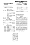
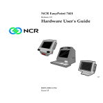
',0(16,216
unit: mm
88.90
95.00
73.60
85.70
100.00
16.10
80.00
12.32
5.08
152.15
160.00
3.0
1.6
31.0
Figure 2.1 IPM486 Top View
Figure 2.2 IPM486 Front View
Note:
- G-96 busconnector holes ∅ 2.1 mm (including rivets, standard)
- G-96 busconnector holes ∅ 2.6 mm (without rivets, non standard)
- all other mounting holes ∅ 3.3 mm
1998 by MPL AG
10
MEH-10059-001 Rev. D
,30,30
8VHU0DQXDO
5(/$7(''2&80(176
The high integration level of equipped components offers a lot more features than could possibly be
described within the scope of this manual. Several data books related to all the different components are
available either directly by its manufacturer or distributors or by Internet.
The following list names the manufacturer and component with the related documentation, mostly found on
Internet as PDF files:
• $P;';:3SURFHVVRU';
Documentation is found on AMD’s web page http://www.amd.com with technical reference manuals and
some application notes. The following direct link may be used:
- http://www.amd.com/products/lpd/techdocs/techdocs.html
(1)
Related documents may also be found on the Intel web page http://www.intel.com with a list of many
different processor manuals. A possible direct link is:
- http://www.intel.com/design/intarch/
(1)
You may also request the Intel486 Programmer’s Reference Manual, order# 240486-003 and the Intel486
Processor Family Manual, order# 242202-003 via Intel’s Literature Center.
• 237L&09%FKLSVHW
The 82C465MV/MVA/MVB Rev. 2.0 Data Book is downloadable as file db016_20.pdf on OPTi’s web
page http://www.opti.com with additional documentation and free software. The direct link is:
- ftp://ftp.opti.com/pub/chipsets/system/465/db016_30.pdf
(1)
(3.5MB)
• 237L&69*$FRQWUROOHU
The 92C178 Data Book is downloadable as file db027_11.pdf on OPTi’s web page http://www.opti.com
with additional documentation and free software. The direct link is:
- ftp://ftp.opti.com/pub/document/dbooks/db027_11.pdf
(1)
(2.0MB)
The Documentation Kit (including VGA BIOS interface) is located at:
- ftp://ftp.opti.com/pub/document/misc/dk006_11.pdf
(1)
(1.5MB)
• 60&)'&&8OWUD,2
The FDC37C93X data sheet is downloadable on SMC’s web page http://www.smsc.com with the direct
link:
- http://www.smsc.com/main/catalog/fdc37c93x.html
(1)
(0.8MB)
Note:
(1)
As of the writing of this manual these links were tested but may have been changed in the
meantime.
1998 by MPL AG
11
MEH-10059-001 Rev. D
,30,30
8VHU0DQXDO
35(3$5$7,21)2586(
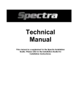
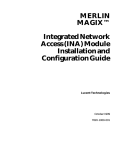
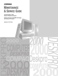
3$576/2&$7,21
J5
E-IDE
ISP
FDD
Parallel
Serial
Mouse
SO-DIMM DRAM
SMC
Ultra I/O
Am5X86
133MHz
0/1
2/3
2
IDE LED
(green)
SO-DIMM Flash
1
Keyboard
G-96 Bus
Power LED
(green)
OPTi
SVGA
OPTi
465MVB
Panel
SVGA CRT
External Power
S1
PC/104
S2
CAN
Figure 3.1 Parts Location
1998 by MPL AG
12
MEH-10059-001 Rev. D
,30,30
8VHU0DQXDO
6:,7&+6(77,1*6
Default switch settings are shown in brackets (x), 0 = OFF, 1 = ON.
Switch S1
S1/1
S1/2 .. S1/3
1
0
1
1
0
0
S1/4
1
0
1
0
S1/5
S1/6 .. S1/7
1
0
1
0
1
1
0
0
1
0
1
0
S1/8
1
(0)
Table 3.1 Display Settings
Switch S2
0
1
0
(1)
0
1
0
1
S2/4 .. S2/5
(0)
(2)
1
0
1
S2/6
S2/1 .. S2/3
(1)
0
0
0
(0)
1
1
1
1
(0)
1
S2/7
(0)
1
S2/8
0
(1)
Table 3.2 System Settings
Meaning
dual scan panel
single scan panel (and TFT)
STN mono 4-bit (single), mono 8-bit (dual)
STN mono 8-bit (single)
STN color 8-bit
STN color 16-bit
STN panel
TFT panel
640x480 panel resolution
800x600 & 1024x768 high resolution panel
240 line pulses per frame (640x480 TFT)
242 line pulses per frame
244 line pulses per frame
800x600 panel (STN or TFT)
VGA enable on 03C3h
VGA enable on 46E8h
0
0
1
(1)
0
0
1
1
(0)
0
1
1
TFT 9-bit
TFT 12-bit
TFT 3-bit
TFT 18-bit
Meaning
System = 16.7MHz, CPU = 50.0MHz
System = 16.7MHz, CPU = 66.7MHz
System = 33.3MHz, CPU = 100.0MHz
System = 33.3MHz, CPU = 133.3MHz
System = 25.0MHz, CPU = 75.0MHz
System = 25.0MHz, CPU = 100.0MHz
System = 30.0MHz, CPU = 90.0MHz
System = 30.0MHz, CPU = 120.0MHz
No Flash Disk
Flash Mirror C8000 - CFFFF
Flash Mirror D0000 - D7FFF
Flash Mirror D8000 - DFFFF
BIOS write protected
BIOS writable
BIOS normal
BIOS update (booting from external BIOS or switching after boot)
onboard battery backup off
onboard battery backup on
Notes:
(1)
In case of an equipped 100MHz processor, you may configure it as a 133MHz processor as well, but
no guarantee is given for perfect functionality.
(2)
These switches are for bootable On-Board SO-DIMM Flash Disk use only. In any other case (e.g.,
bootable Flash Disk or PCMCIA on PC/104), they must remain in "No Flash Disk" setting!
1998 by MPL AG
13
MEH-10059-001 Rev. D
,30,30
8VHU0DQXDO
0(025<
'5$0
Two 72-pin SO-DIMM sockets with JEDEC standard layout (PD pins not used) are available for system
memory. SO-DIMM memory modules are available in sizes of 4, 8, 16 and 32 MBytes. Since the IPM486
does not make use of presence detect, special dedicated layout modules for several different notebook
computers should also work. With two memory modules equipped, a maximum amount of 64 MBytes system
memory is possible. However, the standard maximum amount of DRAM supported is 48MByte and with G-96
bus enabled 32MByte. 64Mbyte is an option available by request.
The IPM486 accepts Fast Page Mode memory (with a special BIOS upgrade, EDO memory can be used,
which results in a performance improvement of about 10 percent). If EDO RAM is required, please contact
your local distributor or MPL AG.
Using only one SO-DIMM DRAM module is possible with socket 0/1 populated.
Electrical and mechanical requirements:
• 5V type
• Unbuffered
• Gold contacts (tin contacts would also work but are not recommended)
• Speed 70ns or faster
• JEDEC Standard SO-DIMM 72-Pin layout
• 4 MB module with 1k refresh
• 8 MB module with 1k (2 banks) or 2k (1 bank) refresh
• 16 MB module with 2k refresh
• 32 MB module with 2k (2 banks) or 4k (1 bank) refresh
)/$6+
The third socket is used for SO-DIMM Flash modules which are available in sizes of 1 to 16 MBytes. It builds
a bootable Flash disk via a 32k mirror area in the memory map, configurable between mirror boundaries of
C8000h to DFFFFh.
To configure the mirror boundaries of the BIOS extension is only necessary for the On-Board SO-DIMM
Flash Disk. If the SO-DIMM Flash Disk is not used as boot device or in any other case, it should be
configured for no Flash Disk.
PLEASE INSERT MEMORY MODULES VERY CAREFULLY!
1998 by MPL AG
14
MEH-10059-001 Rev. D
,30,30
8VHU0DQXDO
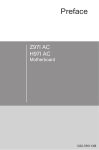
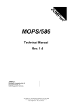
0(025<$1',20$3
MEMORY
FFFFFFFFh
I/O
BIOS
FFFFh
FFFE0000h
82000000h
FLASH
81000000h
Unused
04000000h
VMA(2) G96
03000000h
7000h
INT-Vector
VMA(1) G96
read G-96
02000000h
6000h
EPLD
EXT Memory
Registers
5000h
00100000h
Unused
4800h
BIOS
VGA en.
Unused
VGA BIOS
4000h
000E0000h
VPA async
000C8000h
000C0000h
3000h
VGA Buffer
VPA sync
000A0000h
2000h
Memory
BIOS Data
BIOS Stack
User Vectors
INT Vectors
CAN
1000h
00000500h
Unused
00000400h
00000300h
0400h
000001E0h
AT I/O
00000000h
0000h
Figure 3.2 IPM486 Memory Map
1998 by MPL AG
15
MEH-10059-001 Rev. D
,30,30
8VHU0DQXDO
&211(&7256
3$5$//(/6(5,$/0286(&211(&725-
J3 is a 50-pin HIROSE high density connector (male) with the signals for a parallel port, a PS/2 mouse port
and two RS232 ports. Besides these standard ports, this connector also features 3 general purpose I/Os.
The pinout of this connector is designed for a 1:1 wiring with flat ribbon cables to standard DB25 (parallel
port) and DB9 (serial ports) connectors.
Counterpart is the HIROSE MINI-FLEX connector HIF6-50D-1.27R.
Pin number Signal
Pin number
1
/Strobe
26
2
/Auto Line Feed
27
3
Data0
28
4
/Error
29
5
Data1
30
6
/Init
31
7
Data2
32
8
/Select In
33
9
Data3
34
10
GND
35
11
Data4
36
12
GND
37
13
Data5
38
14
GND
39
15
Data6
40
16
GND
41
17
Data7
42
18
GND
43
19
/Acknowledge
44
20
GND
45
21
Busy
46
22
GND
47
23
Paper End
48
24
GND
49
25
Select
50
Table 3.3 Parallel-, Serial-, Mouseport
Signal
GND
RI1
DTR1
CTS1
TXD1
RTS1
RXD1
DSR1
DCD1
GND
RI2
DTR2
CTS2
TXD2
RTS2
RXD2
DSR2
DCD2
MSDAT
MSCLK
VCC
GND
GPIO15
GPIO16
GPIO17
.(<%2$5'&211(&725
Standard PS/2 pinout (6-bin mini-DIN, female). A PC/AT keyboard can also be connected with an adapter.
Pin number Signal
1
KDAT
2
NC
3
GND
4
VCC
5
KCLK
6
NC
Table 3.4 Keyboard Connector
1998 by MPL AG
Figure 3.3 Keyboard Connector
16
MEH-10059-001 Rev. D
,30,30
8VHU0DQXDO
9*$&57&211(&725
Standard DB15-HD pinout (female). Resolutions up to 1024x768 pixels with 256 colors are possible.
Pin number Signal
1
R
2
G
3
B
4
NC
5
GND
6
GND
7
GND
8
GND
9
GND
10
GND
11
NC
12
NC
13
HSYNC
14
VSYNC
15
NC
Table 3.5 VGA CRT Connector
3$1(/&211(&725
Many different panels can be supported with the onboard VGA controller. Pin names (listed below) on the
40-pin header (HD, male) are for a general overview. Some pins may change with different configurations.
Some signals are available for controlling the power-up sequence (PWDPAN, PANBIAS, PANLGT) for
panels and contrast (CTRL1, CTRL2). The interface signals are 5V based but can be reduced to 3.3V with
additional interface cards.
Pin number Signal
1
FLM / VSYNC
2
LP / HSYNC
3
SCK
4
VCC-POWER
5
VCC-POWER
6
GND-POWER
7
GND
8
UD0 / R0
9
UD1 / R1
10
UD2 / R2
11
UD3 / R3
12
UD4 / R4
13
UD5 / R5
14
UD6 / G0
15
UD7 / G1
16
GND
17
LD0 / G2
18
LD1 / G3
19
LD2 / G4
20
LD3 / G5
Table 3.6 Panel Connector
Note:
Pin number
21
22
23
24
25
26
27
28
29
30
31
32
33
34
35
36
37
38
39
40
Signal
LD4 / B0
LD5 / B1
LD6 / B2
LD7 / B3
DTMG
GND-POWER
M
PWDPAN
PANBIAS
PANLGT
VCC
B4
B5
+12V
VCC-POWER
VCC-POWER
CTRL1
CTRL2
GND-POWER
GND-POWER
Driving a 9(12)-bit panel with the IPM486 is performed by connecting IPM486 color bits 3-5(2-5) to
panel color bits 0-2(0-3)
1998 by MPL AG
17
MEH-10059-001 Rev. D
,30,30
8VHU0DQXDO
The IPM486 is shipped with a BIOS for panel resolutions support of 640x480 or 800x600. If 1024x768 is
required, another BIOS has to be programmed into the Flash chip. It is available from MPL AG.
(,'(&211(&725
Standard 40-pin E-IDE pinout (2.54mm / 0.1inch).
Pin number Signal
Pin number
1
/RESET
21
2
GND
22
3
SD7
23
4
SD8
24
5
SD6
25
6
SD9
26
7
SD5
27
8
SD10
28
9
SD4
29
10
SD11
30
11
SD3
31
12
SD12
32
13
SD2
33
14
SD13
34
15
SD1
35
16
SD14
36
17
SD0
37
18
SD15
38
19
GND
39
20
NC
40
Table 3.7 E-IDE Connector
Signal
DRQ7
GND
/HDDWR
GND
/HDDRD
GND
HDCHRDY
HDBALE
/DACK7
GND
IRQ14
/IOCS16
HDA1
NC
HDA0
HDA2
/HDCS0
/HDCS1
/HDACT
GND
)''&211(&725
Standard 34-pin FDD pinout (2.54mm / 0.1inch).
Pin number Signal
1
GND
2
/RWC
3
GND
4
NC
5
GND
6
/DS3
7
GND
8
/IDX
9
GND
10
/DS0
11
GND
12
/DS1
13
GND
14
/DS2
15
GND
16
/MOT_ON
17
GND
Table 3.8 FDD Connector
1998 by MPL AG
Pin number
18
19
20
21
22
23
24
25
26
27
28
29
30
31
32
33
34
Signal
/DIRC
GND
/STEP
GND
/WDATA
GND
/WGATE
GND
/TR00
GND
/WPROT
MID0
/RDATA
GND
/SIDE_1
MID1
/DSKCHG
18
MEH-10059-001 Rev. D
,30,30
8VHU0DQXDO
-
Connector for Reset Switch, Suspend Switch, Speaker and for a general external chip select.
1
2
SPEAKER
/EXT_CS
RESETSW
SWITCH
3
4
5
6
GND
SWITCH
SUSPSW
VCC
SPEAKER
Figure 3.4 Connector J5
&$1&211(&725
All signals for an opto isolated CAN interface are available on this connector. These are the two serial data
lines and power pins for external power supply (from 9V up to 28V).
1:1 wiring to a standard DB9 connector results in a pinout according to the CiA draft standard CiA/DS 102-1.
Pin number Signal
1
NC
2
EXT-GND
3
CANL
4
CANH
5
EXT-GND
6
NC
7
NC
8
VEXT
9
NC
10
NC
Table 3.9 CAN Connector
,63
This connector is for MPL internal use only. Pin 2 and Pin 4 may be used to connect a heat sink with fan for
the CPU (Pin 2 = GND, Pin 4 = VCC [5V], all others are reserved).
(;7(51$/32:(5
This connector is needed if no power via G-96 bus is provided. No other inputs than these and the power
inputs on the G-96 bus must be used to power the board.
Pin number Signal
1
VCC
2
+12V
3
-12V (-5V for PC/104 is generated from -12V)
4
GND
Table 3.10 External Power Connector
TM
Counterpart is the MOLEX Mini-Fit, Jr.
39-01-2040
1998 by MPL AG
connector 5557-NR with female crimp terminal 5556-*, part number:
19
MEH-10059-001 Rev. D
,30,30
8VHU0DQXDO
*,17(5)$&(
(1)
The G-96 bus interface is available at connector J15 which is of type DIN41612, male and with 96 pins.
Table 3.11 gives a list of the signals that are used by the IPM486. G-96 signals not mentioned in the table
below are not connected on the IPM486. The column "Type" represents the view from the IPM486.
Signal
Type
Description
D0 - D15
I/O
Data lines
A0 - A23
Out
Address lines
/VPA
Out
Valid peripheral signal
/VMA
Out
Valid memory address
/DS1, /DS0
Out
Data strobes upper/lower
R/W
Out
Read/Write signal
/BR, /BGACK In
Bus request/acknowl.
/BG
Out
Bus grant
/IRQ1 -5, /NMI In
Interrupt lines
/RES
OC Out Reset
(2)
E
Out
CPU enable
(2)
SYCLK
Out
System clock
/IACK
Out
Interrupt acknowledge
/BERR
In
Bus error
/HALT
In
CPU halts
/DTACK
In
Data acknowledge
(3)
/PWF
In
Power fail
/PAGE
Out
Memory expansion
CHOUT
Passive Dasy chain out
(4)
VBB
In
Power
(5)
+5V
In
System power input
(5)
+/- 12V
In
System power input
(5)
GND
In
System power input
Table 3.11 G-96 Interface (IPM486 only)
Comment
On the G-96 bus inverted
Internally connected to A1 - A24
Valid within 2 kWord
Covers memory range of 32 MB
Valid during VPA and VMA cycles
Selects data direction
Used for bus arbitration
Used for bus arbitration
Combined to one PC interrupt
Open Collector Output (not bi-directional)
AT-Clock / 8 (standard 1MHz)
Board AT-Clock (standard 8MHz)
Acknowledge for vectored IRQ levels
Combined with other G-96 interrupts
Combined with other G-96 interrupts
Terminates asynch. data accesses
Connected to chipset
Connected to address line A25
Pulled up to +5V
Ext. battery supplies RTC/CMOS RAM
Power input to the IPM486
Power input to the IPM486
Power input to the IPM486
Notes:
(1)
For more detailed signal information refer to the G-64/96 Specifications Manual Rev. 3.
(2)
AT-Clock is adjustable with chipset registers between 3MHz up to 24MHz. The board comes up with
an 8MHz clock, which normally should not be changed.
(3)
In older G-64 bus designs (prior to 1984), pin 29a is a -5V input and has to be open. Since then, pin
29a has changed its function and has become a Power Fail input which is supported by the IPM486.
(4)
The external battery connects directly (via shottky diode and resistor) to the CMOS RAM and RTC
and cannot be switched off on board.
(5)
These are the power inputs to the IPM486. No other inputs (except power inputs on the dedicated
power connector) must be used to power the board.
1998 by MPL AG
20
MEH-10059-001 Rev. D
,30,30
8VHU0DQXDO
3&,17(5)$&(
(1)
The PC/104 bus interface (female) is available at connector J6 for modules with 2.54mm (0.1inch) header.
(2)
Table 3.12 gives a list of the signals that are used by the IPM486. The column "Type" represents the view
from the IPM486.
Signal
Type
SD0 - SD15
I/O
SA0 - SA19
I/O
LA17 - LA23
I/O
(3)
IRQ3 - IRQ15
In
(4)
DRQ0 - DRQ7
In
(4)
/DACK0 - /DACK7
Out
AEN
Out
/SMEMW, /SMEMR
Out
/MEMW, /MEMR
I/O
/IOW, /IOR
Out
(5)
/MEMCS16, /IOCS16
In
/IOCHCK
In
/IOCHRDY
In
/REFRESH
I/O
RESETDRV
Out
BALE
Out
TC
Out
/MASTER
In
/SBHE
I/O
OSC
Out
(6)
SYSCLK
Out
+/- 5V
Out
+/- 12V
Out
GND
Out
Table 3.12 PC/104 Interface
Description
Data lines
Address lines
Address lines
PC interrupts
DMA Request
DMA Acknowledge
Address Enable
Memory Write / Read
Memory Write / Read
I/O Write / Read signals
16-Bit chip select
I/O Channel Check
I/O Channel Ready
AT-Bus Refresh
Reset
Bus Latch Enable
Terminal Count
Master acknowledge
System Byte High Enable
14.31818MHz
AT bus clock
Power output
Power output
Power output
Comment
On 8-Bit connector
On 16-Bit extension
excluding IRQ8. IRQ13
excluding DRQ4
excluding /DACK4
DMA has taken control address, AT command
accesses below 1MB
accesses into full ISA range (16MB)
Selects data direction
Indicates support of 16-Bit accesses
Indication of a bus error
Inactive when bus resource needs further cycles
Indicates AT-Bus refresh cycle
AT-Bus reset, connected to system Reset
Validation of address and some control signals
Indicates the end of a DMA data transfer
Address lines are inputs
Valid data on SD8 - SD15
Not synchronized to any other signal
Standard 8MHz, adjustable
Power for PC/104 extension cards
Power for PC/104 extension cards
Power for PC/104 extension cards
Notes:
(1)
For more detailed information refer to the PC/104 Specification, Version 2.3 and to the IEEE P996
draft standard (D2.02). The PC/104 Specification may be downloaded from Ampro’s home page at:
www.ampro.com/forum/specs/pc104-23.pdf
(2)
The signal /ENDXFR (/NOWS) is not provided.
(3)
Some interrupt channels may be in use of some onboard periphery.
(4)
Some DMA channels may be in use of some onboard periphery.
(5)
/MEMCS16 is output when external bus master is active.
(6)
AT-Clock is adjustable with chipset registers between 3MHz up to 24MHz. The board comes up with
an 8MHz clock, which normally should not be changed. For more information please refer to the
OPTi82C465MVB Data Book, Revision 2.0
1998 by MPL AG
21
MEH-10059-001 Rev. D
,30,30
8VHU0DQXDO
:,5,1*2)&211(&7256
3$5$//(/3257
Wired 1:1 with flat cable from 50-pin connector J3 to standard DB25 (female) connectors.
Pin J3 Signal
Pin DB25
1
/Strobe
1
2
/Auto Line Feed
14
3
Data0
2
4
/Error
15
5
Data1
3
6
/Init
16
7
Data2
4
8
/Select In
17
9
Data3
5
10
GND
18
11
Data4
6
12
GND
19
13
Data5
7
14
GND
20
15
Data6
8
16
GND
21
17
Data7
9
18
GND
22
19
/Acknowledge
10
20
GND
23
21
Busy
11
22
GND
24
23
Paper End
12
24
GND
25
25
Select
13
Table 3.13 Wiring of Parallel Port
6(5,$/32576
Wired 1:1 with flat cable from 50-pin connector J3 to standard DB9 (male) connectors.
Pin J3 (Port 1) Signal
Pin DB9
26
GND
5
27
RI1
9
28
DTR1
4
29
CTS1
8
30
TXD1
3
31
RTS1
7
32
RXD1
2
33
DSR1
6
34
DCD1
1
Table 3.14 Wiring of Serial Ports
1998 by MPL AG
Pin J3 (Port 2)
35
36
37
38
39
40
41
42
43
Signal
GND
RI2
DTR2
CTS2
TXD2
RTS2
RXD2
DSR2
DCD2
22
Pin DB9
5
9
4
8
3
7
2
6
1
MEH-10059-001 Rev. D
,30,30
8VHU0DQXDO
360286(
Wired from 50-pin connector J3 to standard 6-pin mini-DIN (female) connector.
Pin J3 Signal
Pin mini-DIN
44
MSDAT
1
NC
2
47
GND
3
46
VCC
4
45
MSCLK
5
NC
6
Table 3.15 Wiring of PS/2 Mouse
Figure 3.5 PS/2 Mouse Connector
$33/<,1*32:(5,16,1*/(%2$5'$33/,&$7,216
In each case, power to the IPM486 must be applied at G-96 connector or External Power connector. All other
connectors which do have power pins as well MUST NOT be used to power the board. The required supply
voltages are at minimum +5V.
In single board application where the IPM486 is not mounted on a G-96 backplane, the power supply must
be connected to the G-96 connector with as many pins as possible (to insure solid +5V and GND) or to the
External Power (Molex) connector.
+12V is required to supply the PC/104 module (if +12V is not generated on the PC/104 extension board
itself).
-12V is required to supply the PC/104 module (if -12V is not generated on the PC/104 extension board itself)
and to generate -5V supply for PC/104 boards (-5V may be generated on the PC/104 extension board as
well).
1998 by MPL AG
23
MEH-10059-001 Rev. D
,30,30
8VHU0DQXDO
23(5$7,21
10-pin
connector
%/2&.',$*5$0
CAN
opto-isolated
BIOS
40-pin connector
(Standard type)
CPU
Am5X86-133WB
E-IDE
Flash Disk
34-pin connector
(Standard type)
(up to 16MB)
FDD
Battery
DRAM
RTC
CMOS RAM
Keyboard
SMC Ultra I/O
Mouse
4
RS232
OPTi92C178
9
CHIPSET
OPTi82C465MVB
RS232
9
50-pin connector
(HD type)
FDC37C935
SVGA
Panel 40-pin micro connector
(with 2 I/Os and 3 power control lines)
6-pin
Mini-DIN
VGA 15HD connector
(Standard type)
(up to 64MB)
Parallel Port
G-96 interface
PC/104 interface
(SPP/EPP/ECP)
I/O
25
3
Figure 4.1 IPM486 Block Diagram
3&$7)81&7,21$/,7<
The IPM486 operates as a standard PC/AT with all dedicated registers for:
• Timer
• Interrupt controller
• DMA controller
• Real Time Clock
• Keyboard controller
• Parallel, Serial ports
• E-IDE controller
• FDD controller
• VGA controller
1998 by MPL AG
24
MEH-10059-001 Rev. D
,30,30
8VHU0DQXDO
67$786,1',&$7256
The IPM486 provides two status indicator LEDs, giving the user visual response to the actual status. The
LEDs are mounted on the solder side at the upper card front. Please refer to Figure 3.1 for their exact
location.
32:(5,1',&$725/('
The green Power LED indicator is lit whenever +5V power is applied to the board.
,'($&&(66,1',&$725/('
The green IDE Access indicator is lit whenever an IDE device is accessed.
%$77(5<&,5&8,7
An on board battery is provided to guarantee data retention of RTC and CMOS RAM in power down
situations. Battery backup of these two devices is enabled at dip-switch S2/8.
The battery’s capacity of 160mAh should always be sufficient for every application. However, if required, an
external battery can be used to support data retention of RTC and CMOS RAM. This battery must be
connected to pin 29B of connector J15 (G-96 connector) and connects directly (via shottky diode and
resistor) to the RTC and CMOS RAM. This battery cannot be switched off on board and supplies the devices
regardless of the setting of the corresponding switch on S2. If the internal and external battery sources are
present, the source with the higher output voltage will supply the RTC and CMOS RAM.
&$87,21
The external battery voltage should not exceed the range of 2.4V to 4.0Vdc
(0&)($785(6
The IPM486 provides all aspects of quality demanded of an industrial computer system. Development
according to EMC requirements supports the user in achieving the CE conformity on the system level. This
covers features like on board protection and filter devices on power and I/O lines as well as a carefully
designed layout.
In a system design, two aspects regarding EMI must be observed. These aspects are immunity to (external)
disturbances and prevention of Radio Frequency emissions (RF). On the IPM486, both aspects are taken
into account.
Some immunity is given for free since many components do already contain internal circuits providing at
least minor protection to ESD. However, special protection devices are provided at exposed locations. As a
side effect, the load capacitance of these devices also reduces RF emission slightly.
Immunity and RF emission is kept to a minimum by the 8-layer PCB design. The arrangement of the power
planes is lowering the board impedance and improving the RF behavior. The various on board interfaces are
grounded separately and connected together at a fixed point (G-96 and power connector power inputs)
which prevents disturbing loop currents. The top and bottom layer provide so called "ESD rails" along their
long side card edges. These rails are separately grounded and are especially helpful when the IPM486 is
used in a rack system equipped with ESD board guides. If a (metal) front panel is to be used, it may be fixed
to the board by metal holders and therefore will be grounded separately as well.
RF emissions are additionally kept low by the use of series resistors in clock and high speed lines. Several
interface signals contain special filter devices to reduce emitted radiation and to protect against imission.
The table below gives an overview over the ESD and Surge protected interfaces and the appropriate I/O
pins. The protection levels are taken from the corresponding data sheets and do not represent actual
measurements. All other Interfaces are protected according to their filter device.
1998 by MPL AG
25
MEH-10059-001 Rev. D
,30,30
8VHU0DQXDO
Interface
I/O Pins
G-96 Interface and
+5V / +12V / -12V
Power Input
CAN Interface
Power input
RS-232 Interface
RS-232 lines
Parallel Interface
all signals
TTL Interface
on 50-pin HD connector
PS/2 mouse
data/clock
Table 4.1 ESD/Surge Protection
Level
600 W
Condition
10µs/1000µs
600 W
15 kV
4 kV
4 kV
4 kV
10µs/1000µs
(1)
HBM
(1)
HBM
(1)
HBM
(1)
HBM
(;7(1'(')81&7,21$/,7<
Basically three non standard extensions are implemented on the IPM486 which are a Flash Disk, G-96 bus
and CAN interface. For the use of these extensions, it is recommended to have the 16 bit address
(1)
qualification of the chipset to be set for I/O accesses above 3FFh (please refer to IPM486 memory map).
The chipset registers are accessed via index and data port.
INDEX
0x22h
DATA
0x24h
Table 4.2 Chipset Register Access
For every read and write access to a chipset register, the index/data method has to be used. To change the
address qualification mode, write the appropriate value to register A0h (A0h[7] = 1 -> 16 bit qualification,
A0h[7] = 0 -> 10 bit qualification) according to the following principle:
mov
mov
out
mov
in
or
xchg
mov
mov
out
mov
xchg
out
DX, 022h
AL, 0A0h
DX, AL
DX, 024h
AL, DX
AL, 080h
AL, AH
DX, 022h
AL, 0A0h
DX, AL
DX, 024h
AL, AH
DX, AL
Figure 4.2 Chipset Register Programming
A DOS utility is available to enable/disable 16 bit address decoding. To change decoding state, run the
"add16.exe" utility with the needed parameter:
C:\add16.exe on/off
Note:
(1)
The BIOS is booting with 16 Bit address qualification on.
1998 by MPL AG
26
MEH-10059-001 Rev. D
,30,30
8VHU0DQXDO
(;7(16,215(*,67(56
Extension registers are all present regardless of an equipped (IPM486) or not equipped (IPM5) G-96 bus. In
case of an IPM5, the G-96 registers may be programmed and the system will act as if the G-96 bus would be
present (memory map and occupied IRQ line) but without the needed interface. Therefore programming
dedicated G-96 registers on IPM5 may lower free system resources without any advantage.
5(9,6,21180%(5*3$*(5(*,67(5
The Revision Number / G-96 Page register has two different assignments, distinguished by reading or writing
the register. A read from the register returns the revision code of the actual EPLD, a write sets the G-96 page
(1)
address lines A23 - A16
(the remaining two address lines A24 and A25 are set through register 5001h,
Page Control).
The EPLD revision code has the format:
HR1 HR0 . LR2 LR1 LR0
Read
D7
D6
D5
reserved reserved reserved
D4
HR1
D3
HR0
D2
LR2
D1
LR1
D0
LR0
Revision Number
5000h
D4
PA20
D3
PA19
D2
PA18
D1
PA17
D0
PA16
G-96 Paging Addr.
5000h
(2,3)
Write
D7
PA23
D6
PA22
D5
PA21
Register 5000h read
Bit
Number
7-5
Reserved:
reading always returns 0
4,3
Revision Code for the actual EPLD:
higher digit
2-0
Revision Code for the actual EPLD:
lower digit
Function
(3)
Register 5000h write (extended IPM486 version)
Bit
Function
Number
7-0
G-96 Paging Address (CPU addresses):
If G-96 paging is enabled, these bits control the G-96 paging address-bits PA23 - PA16
Paging Addresses PA24 and PA25 are found in register Page Control.
Table 4.3a Revision Number / G-96 Page Register
Note:
(1)
A16 - A25 are CPU addresses. Since the G-96 bus is a 16 bit device, these addresses correspond
with the G-96 addresses A15 - A24.
(2)
Reading the Paging Address is not possible. The Software has to take care of the register settings.
(3)
G-96 address paging is only available by request and is not possible with the standard IPM486. In
general, accessing the VMA area should be performed via protected mode accesses. Please contact
MPL AG for any assistance in switching between different modes.
1998 by MPL AG
27
MEH-10059-001 Rev. D
,30,30
8VHU0DQXDO
3$*(&21752/5(*,67(5
D7
GPAG
D6
PAGA2
D5
PAGA1
D4
PAGA0
D3
PAGAW
D2
GPAW
D1
GPA25
D0
GPA24
Page Control
5001h
Register 5001h
Bit
Function
Number
7
G-96 Paging Enable:
1: G-96 paging into Upper Memory enabled
0: G-96 paging into Upper Memory disabled
This bit is only writable with PAGAW = 0 and GPAW = 0.
This bit is always readable.
6-4
Page Address for G-96 bus and Flash Disk:
These bits are only writable with D3 (PAGAW) set to 1, otherwise no write is accepted.
These bits are always readable.
PAGA2 PAGA1 PAGA0
Flash-Base VMA-Base
---------------------------------------------0
0
0
disabled
C8000h
0
0
1
disabled
D8000h
0
1
0
disabled
D0000h
0
1
1
C8000h
D0000h
1
0
0
D0000h
C8000h
1
0
1
D0000h
D8000h
1
1
0
D8000h
D0000h
1
1
1
D8000h
C8000h
After reset, PAGA2 and PAGA1 are reflecting the settings of configuration switches S2/5 and
S2/4, PAGA0 is set to 1.
3
Page Address Write Enable:
For a write to PAGA2 - PAGA0, this bit has to be 1, otherwise no change is accepted.
Reading this bit will always return a 0.
2
G-96 Address Write Enable:
For a write to GPA25 and GPA24, this bit has to be 1, otherwise no change is accepted.
Reading this bit will always return a 0.
1, 0
G-96 Paging Address:
If G-96 paging is enabled, these bits control the G-96 paging address-bits PA25 and PA24
Paging Addresses PA23 - PA16 are found in register G-96 Paging Address.
These bits are only writable with D2 (GPAW) set to 1, otherwise no write is accepted.
Reading these bits will always return 0.
Table 4.3b Page Control Register
Note:
G-96 address paging is only available by request and is not possible with the standard IPM486.
Although the register fully exists as described above, G-96 paging extensions will have no effect in
conjunction with a standard IPM486. In general, accessing the VMA area should be performed via
protected mode accesses. Please contact MPL AG for any assistance in switching between different
modes.
1998 by MPL AG
28
MEH-10059-001 Rev. D
,30,30
8VHU0DQXDO
,543(1',1*5(*,67(5
Reading the IRQ Pending register shows the pending G-96 interrupts as a 1, cleared interrupts as a 0.
All G-96 interrupt request lines are combined to one PC interrupt according to Control register settings.
Special care has to be taken for reading this register. After every read, /BERR and /NMI states are reset to 0.
The states have to be saved by software to insure that no interrupt request is lost. HALT and IP5-IP1 are
reflecting the actual state of the corresponding G-96 bus state.
Writing to the register configures IRQ routing and VMA area options. Enabling G-96 or CAN control signals
(Control register 5003h) enables routing of G-96 and CAN Interrupts to PC Interrupts as well. To prevent
from routing any G-96 / CAN Interrupt to PC lines, IRQPC bit can be set.
To avoid address conflicts with some SVGA drivers, the upper VMA(2) range will only be active if VMA2 bit is
set.
Read
D7
BERR
D6
HALT
D5
IP7/NMI
D4
IP5
D3
IP4
D2
IP3
D1
IP2
D0
IP1
D1
IRQPC
D0
VMA2
IRQ Pending
5002h
(1)
Write
D7
D6
D5
D4
reserved reserved reserved Reserve
d
D3
D2
reserved reserved
Config
5002h
Register 5002h read
Bit
Function
Number
7
G-96 Bus Error:
Indicates that an error occurred during data transfer or a parity error while reading from a
memory module.
Always auto vectored
This edge sensitive interrupt request state is latched until a read of IRQ Pending register.
Afterwards it is reset to 0.
6
Halt Processor:
On the IPM486, HALT is combined with other interrupt request lines to one PC interrupt to leave
the decision to the programmer whether it should be handled or not.
Always auto vectored.
5
G-96 Interrupt Request (Non Maskable Interrupt):
Always auto vectored.
This edge sensitive interrupt request state is latched until a read of IRQ Pending register.
Afterwards it is reset to 0.
4-0
G-96 Interrupt Request IRQ5 - IRQ1:
Vectored or auto vectored interrupt request.
Register 5002h write
Bit
Function
Number
7-2
Reserved, write 0 to these bits
1
PC-IRQ Suppression (see section 4.6.2.1)
1: PC-IRQ (IRQ5/11/15) free for other PC/104 devices
0: PC-IRQ (IRQ5/11/15) used for routing CAN and G-96 Interrupts (default)
0
VMA(2) enable (see section 4.6.2.2)
1: VMA(1) and VMA(2) is active from 02000000h to 04000000h
0: VMA(1) is active only from 02000000h to 03000000h (default)
Table 4.3c IRQ Pending / Config Register
Note:
(1)
Reading the Config data is not possible. The software has to take care of the register settings.
1998 by MPL AG
29
MEH-10059-001 Rev. D
,30,30
8VHU0DQXDO
&21752/5(*,67(5
With the Control register, PC/AT interrupt levels are set and Flash wait states are configured. G-96 clocks
can be enabled or disabled and the CAN controller is put into reset or enabled. One configurable PC/AT
interrupt is occupied for all G-96 interrupts and one for the CAN controller.
D7
ENGC
D6
CEN
D5
FLWS1
D4
FLWS0
D3
ILC1
D2
ILC0
D1
ILG1
D0
ILG0
Control
5003h
Register 5003h
Bit
Function
Number
7
Enable G-96 Clock:
1: Enable G-96 clocks
0: Disable G-96 clocks
6
CAN Enable:
1: CAN active
0: CAN reset
5, 4
Flash Disk Waitstates:
00: 2WS (90ns) @ 33MHz system clock
01: 3WS (120ns) @ 33MHz system clock (default)
10: 4WS (150ns) @ 33MHz system clock
11: 5WS (180ns) @ 33MHz system clock
(1)
3, 2
AT Interrupt for CAN Bus :
00: no interrupt
01: IRQ5
10: IRQ11
11: IRQ15
CAN control signals are disabled if no AT interrupt is enabled. Any enabled AT interrupt enables
the CAN controller but leaves the controller into reset state if bit 6 (CEN) is 0.
(1)
AT Interrupt for G-96 Bus :
00: no interrupt
01: IRQ5
10: IRQ11
11: IRQ15
1, 0
G-96 bus control signals are disabled if no AT interrupt is enabled. Any enabled AT interrupt
enables the G-96 bus but it does not automatically enable G-96 clocks. If these clocks are
needed (e.g. VPA sync.), bit 7 (ENGC) has to be set.
Table 4.3d Control Register
Note:
(1)
Enabling AT interrupts for G-96 and CAN does not automatically enable the corresponding PC
interrupt. It only decides if G-96 and CAN interface signals will be active and if G-96 and CAN
interrupts are carried to one of three PC interrupts. PC interrupts have to be enabled separately on
PC-Interrupt Controller.
If one or both interfaces are enabled via bits 0-3, the designated PC-Interrupt line is in use and not
free anymore for other PC/104 devices except the suppression bit in Config register (5002h write) is
set.
1998 by MPL AG
30
MEH-10059-001 Rev. D
,30,30
8VHU0DQXDO
*%86,17(5)$&(
CAUTION:
Writing to the synchronous VPA I/O range (2000h to 2FFFh) without G-96 clocks enabled
(Control register) will trigger a G-96 /BERR. This may happen for example with Microsoft
MSD. Make sure that the interrupt is handled correctly, at least with a default handler.
$''5(66,1*2)3(5,3+(5$/'(9,&(6$1'0(025<
Please refer to the IPM486 memory map (Figure 3.2) to see where VMA, VPA sync. and VPA async. are
located.
The G-96 interface opens access to numerous G-64 and G-96 compatible products and therefore allows for
a flexible I/O and memory extension. MPL AG offers a broad range of G-96 products covering functions like
memory and mass storage extensions, serial and parallel interfaces, analog circuits, etc.
The IPM486 offers a full implementation of the G-96 (and G-64) bus interface (except DMA cycles to CPU
memory and I/O space). Bus arbitration capability is provided allowing external bus arbiters to take control of
the bus. Two address fields of 2 kWord each allow to access synchronous and asynchronous bus
peripherals individually in the predecoded VPA range. However, each address used in the synchronous field
must be omitted in the asynchronous field, and vice versa. Up to 32 MByte in the asynchronous VMA range
can be addressed (due to the decoded VMA area, the G-96 PAGE signal is always high).
To enable the G-96 bus, one of three possible PC interrupts has to be set for the G-96 bus (Control register
bit 0,1). This only enables the G-96 control signals and all G-96 interrupts to the corresponding PC interrupt.
Nevertheless an interrupt is only processed if the PC’s interrupt controller is enabled as well. If the G-96 bus
interface is not used, it should be left disabled (high-z). For accesses which do not make use of G-96 clocks
(e.g., asynchronous accesses), these clocks may be turned of (or may be left inactive) with ENGC bit (bit 7)
of the Control register.
Routing Interrupts to PC Interrupt lines may be suppressed by writing a 1 to Config register bit IRQPC.
Accessing G-96 bus is still possible (without IRQ requests) while the interrupt line is free for other PC/104
devices.
The G-96 bus appears as a true 16-bit device on single word boundaries to the CPU. Therefore, A1-A25 of
the CPU are connected to A0-A24 of the G-96 bus. When accessing the G-96 bus as a 16 bit device, please
notice, that the G-96 D0-D7 are connected to the CPU’s D8-D15 and the G-96 D8-D15 are connected to the
CPU’s D0-D7. Use even addresses only and increment the addresses by 2 to get the next contiguous
address. Misaligned accesses are split into two read or write cycles by the CPU and therefore are using
twice the amount of time.
When accessing the G-96 bus as an 8 bit device, use odd addresses and increment the addresses also by 2.
These devices are accessed via D0 - D7 on the G-96 bus and due to the Big Endian to Little Endian
transformation are always read at the CPU's D8 - D15.
If a Big Endian device accesses the same location as the IPM486 over the G-96 bus, misaligned addressing
is not allowed. These locations have to be addressed aligned or 8 bit.
$&&(66,1*0%<7(2)90$
Some SVGA drivers (Windows 95/98/NT) are using linear addressing of video memory for better speed. This
address space is located at the top of the IPM486 64Mbyte addressing range (03E00000 to 03FFFFFFh).
To prevent from conflicts, only the lower 16Mbyte VMA(1) range is active by default. If no linear video
memory addressing is used (e.g. QNX, DOS, Windows 3.11, standard video drivers), the second VMA(2)
range can be enabled by writing a 1 to the Config register bit VMA2, resulting in a VMA range of 32Mbyte
from 02000000h to 04000000h.
6<1&+521286*$&&(66(6
Synchronous bus accesses are restricted to the VPA range and are always relative to the Enable Signal (EClock, AT-Clock/8 → normally 1 MHz). Changing AT-Clock changes E-Clock. Refer to the OPTi 82C465MVB
data book for more information.
1998 by MPL AG
31
MEH-10059-001 Rev. D
,30,30
8VHU0DQXDO
$6<1&+521286*$&&(66(6
Asynchronous accesses via the G-96 bus have to be acknowledged by an acknowledgment signal (DTACK)
to indicate that the access can be terminated.
If DTACK is not negated within a defined time after the access has been terminated by the CPU, the next
access will be seen as a "zero wait state" access. To prevent erroneous behavior in such case, the IPM486
starts G-96 accesses only when the bus DTACK is not (no longer) active.
5(6(7:,7+*%86(1$%/('
After a hardware reset, the G-96 bus is always off, even if it was configured to be active before. This is
necessary for the memory check performed by the BIOS during power up self test. If the G-96 interface (and
therefore VMA) remains active (e.g., after a warm start with CTRL/ALT/DELETE), a memory access conflict
occurs and the system will not be able to boot until a hardware reset is performed.
*,17(558376
If a G-96 interrupt is pending, the PC/AT interrupt according to the Control register is triggered and its
handler is called. The PC/AT interrupt handler first has to read the IRQ Pending register.
In case of an autovectored interrupt, the handler has to poll all possible interrupters.
In case of a vectored interrupt, the handler has to read the interrupt vector on the G-96 data lines D0 to D7
(which will be reflected on data lines D8-D15 on the processor local bus) in the VPA area 6000h and to
branch accordingly (contrary to Motorola-based systems, interrupt acknowledge cycles on the IPM486 are
not automated and have to be software coded). Accesses to the interrupt vector read I/O area are always
asynchronous. To access the interrupt vector, the IPM486 addresses the interrupt level with A1 to A3 and
byte enable 1 of the CPU activated. The table below lists all possible interrupts and the needed I/O
addresses to access it:
G-96 interrupt PC/AT I/O address for interrupt vector read
1
6003h
2
6005h
3
6007h
4
6009h
5
600Bh
Table 4.4 G-96 Interrupt Vector Address (IPM486 only)
G-96 IRQ7 reflects the /NMI line of the G-96 bus (this is a MPL-internal naming convention). The
corresponding bit in the IRQ Pending register (D5) will be reset after read. Additionally to these interrupt
sources, the two lines /BERR and /HALT of the G-96 bus will also trigger the corresponding PC/AT interrupt.
Their state is reflected in the D7/D6 bit of the IRQ Pending register. Due to the pulsed occurrence of the
/BERR signal, this state is latched in the D7 bit. After reading the IRQ Pending register, the latch will be
reset.
So take care to the read D7 and D5 bit!
&$1,17(5)$&(
CAN (Controller Area Network) is a powerful solution for field bus applications meeting the general
requirements of field busses, e.g., low cost, reliability, safety, open system, real time capability and easy to
use. CAN especially fulfills the requirement of sensor and actuator systems due to its serial multi master
communication protocol. With its high noise immunity and fail-safe operation it is ideal as a control network
for industrial applications.
On the IPM486, the CAN interface bases upon the CAN Controller PCA82C200 (manufactured by Philips).
The controller is a highly integrated standalone device, containing all necessary modules to perform the
functions of the CAN data link layer. Internal logic blocks (e.g., bit stream processor, acceptance filter, error
and buffer manager) relieve the main processor of permanent intervention by autonomously handling their
tasks.
1998 by MPL AG
32
MEH-10059-001 Rev. D
,30,30
8VHU0DQXDO
To eliminate the effects of compensation currents between digital equipment in long distance installations,
the CAN interface is opto isolated. Since there is no on board DC/DC converter, an external power supply is
required. The power input is reverse polarity protected and accepts voltages from 9V to 28Vdc @ 100mA
maximum.
The CAN driver used (Si9200 or PCA82C250) complies fully with the ISO/DIS 11898 standard and allows for
transfer rates up to 1 Mbit/sec. The CAN transmission medium must be implemented as a differential twowire "wired or" connection, allowing for so called recessive and dominant bus states.
The CAN controller is connected to the ISA bus as an 8 bit device. It can be activated with the Control
Register (refer to chapter 4.6.1.4) by configuring one out of three PC/AT interrupt sources as CAN interrupt
(IRQ5, IRQ11, IRQ15). This only enables the CAN control signals and the CAN interrupt to the
corresponding PC interrupt. Nevertheless an interrupt is only processed if the PC’s interrupt controller is
enabled as well. The CAN interrupt handler has to work similar to every standard PC/AT interrupt handler.
Routing Interrupts to PC Interrupt lines may be suppressed by writing a 1 to Config register bit IRQPC.
Accessing CAN bus is still possible (without IRQ requests) while the interrupt line is free for other PC/104
devices.
All CAN interface signals are available at the CAN connector (refer to chapter 3.4.8), allowing for a simple
flat cable connection to a DB-9 connector which will conform to the Draft Standard DS102-1 as described by
CiA (CAN in Automation; an international group of users and manufacturers of CAN).
The inter cabling of the CAN nodes is usually made with a 4-wire standard cable (2 wires for power, 2 wires
for CAN bus with 120Ω termination).
The power input contains devices to protect against electrostatic discharge (ESD) and electrical fast
transients (EFT, Surge). However, the signal lines have to be protected by the user, depending on the
application and protection grade needed.
,03/(0(17$7,21(66(17,$/6
When initializing the CAN Controller 82C200, some basic of the CAN hardware implementation on the
IPM486 must be known. The information given below might be essential or at least helpful.
The controller is operated in Intel mode and clocked by a 16MHz oscillator. The CLK OUT pin is not used
and left open, however, initializing the Clock Divider Register (CDR) to the highest division ratio (06h) may
reduce RFI. CAN Controller registers are mapped to I/O base address of 1000h according to the IPM486
Memory Map.
The CAN Controller uses pin Rx0 as receive data input to the internal comparator while at pin Rx1 a
threshold voltage of approx. 1.6V is input. Transmission data is output at pin Tx1 while pin Tx0 is left
unconnected.
The Output Control Register (OCR) should be initialized to (C2h). Thus, normal output mode is selected and
Tx1 is in non-inverting push/pull mode while Tx0 is left floating.
The location of the sample point within a bit period is essential to the correct functioning of a transmission.
To determine the sample point, the total propagation delay time of the physical bus and the local hardware
implementation must be known. The hardware implementation on IPM486 sums up to a delay of 270ns
maximum, consisting of the delays of CAN Controller, opto couplers and CAN driver. This value has to be
understood as the time measured from an incoming edge appearing at the CAN bus connector until the CAN
Controller reaction has reached the bus connector again.
The RESET pin of the CAN Controller is controlled by bit CEN (bit 6) in the Control register rather than being
connected to the system reset. This may be helpful in situations where the controller goes bus-off (e.g., due
to an overrun error counter; no acknowledge from other CAN nodes) and cycling the reset line may be the
last resort to bring the CAN Controller back on the bus. Note that after a system reset the CEN bit is low, and
the CAN Controller is in reset state.
1998 by MPL AG
33
MEH-10059-001 Rev. D
,30,30
8VHU0DQXDO
&$162)7:$5(6833257
A CAN device driver for DOS, Windows 3.11 and Windows 95/98 with related documentation is available on
the MPL homepage: http://www.mpl.ch/mpl/support.htm.
86,1*3&$7,17(558376
As every standard PC, the IPM486 provides 17 Hardware interrupt channels, some of them accessible on
PC/104 extension bus. It is the user’s responsibility to make sure that no hardware conflict occurs due to a
wrong interrupt configuration. Please see the table below for IPM486 interrupt assignments.
,30KDUGZDUHLQWHUUXSWDVVLJQPHQW
NMI
Parity Check
IRQ0
Timer
IRQ1
Keyboard
IRQ2
Cascaded interrupts from 2nd PIC (IRQ8-15)
IRQ3
COM2
IRQ4
COM1
IRQ5
Free (or G-96/CAN)
IRQ6
Floppy Disc Controller
IRQ7
LPT1
IRQ8
Real Time Clock
IRQ9
Redirected as IRQ2, Free
IRQ10
Free
IRQ11
Free (or G-96/CAN)
IRQ12
PS/2 Mouse
IRQ13
Math Coprocessor
IRQ14
Hard Disk Controller
IRQ15
Free (or G-96/CAN)
Table 4.5 PC/AT Interrupts
3&
not available
not available
not available
not available
available
available
available
available
available
not available
available
available
available
available
not available
available
available
5HOHDVHGIRU3&XVHE\
----BIOS setup
BIOS setup
G-96 configuration
BIOS setup
BIOS setup
-Free
Free
G-96 configuration
Ultra I/O register setting
-Chipset register setting
G-96 configuration
Note:
Some of these interrupts may be used for custom applications if the assigned device is not used and not
initialized. Disabling may be performed with BIOS setup or via accessing dedicated registers.
86,1*3&$7'0$&+$11(/6
As every standard PC, the IPM486 provides 8 DMA channels, some of them accessible on PC/104 extension
bus. It is the user’s responsibility to make sure that no hardware conflict occurs due to a wrong DMA
configuration. Please see the table below for IPM486 DMA assignments.
,30'0$FKDQQHODVVLJQPHQW
DMA0
Refresh, redirected to DMA4
DMA1
Free
DMA2
Floppy Disk Drive
DMA3
Free (or ECP)
DMA4
Cascade input for DMA0-3
DMA5
Free
DMA6
Free
DMA7
Hard Disk Drive
Table 4.6 PC/AT DMA Channels
1998 by MPL AG
34
MEH-10059-001 Rev. D
,30,30
8VHU0DQXDO
3(5)250$1&(
If the system performance is too low, an upgrade to EDO DRAM support can be performed (requires a BIOS
change) which speeds up the system significantly. Please contact MPL AG or your local distributor if EDO
DRAM is needed.
VW/(9(/&$&+(
The CPU has 16kB Level 1 WB cache which is globally enabled. To disable caching, set register bit (OPTi
chipset, refer to Table 4.2 and Figure 4.2) 35h[1] = 1 .
A DOS utility is available to enable/disable caching. To change caching state, run the "cache.exe" utility with
the needed parameter:
C:\cache on/off
121&$&+($%/($5($
The area of C8000h - DFFFFh will never be cached.
Since the cache controller is only caching system memory or shadow memory, the VMA area cannot be
cached.
For special user defined non cacheable areas, the chipset can be programmed to exclude 2 definable areas.
For more information, please refer to the 82C465MVB Manual or contact MPL AG.
+''3(5)250$1&(
The IPM486 is able to run HDDs with PIO Mode 0 to 3. This is a selectable feature in the BIOS setup.
Experience showed that some Hard Disk Drives are not able to run in the fastest PIO mode even if they
express to do so. In any cases of HDD corruption please reduce cycle speed in the BIOS setup menu and try
again. Altering the PIO mode is not possible if HDD is auto detected. The menu item has to be changed to
"user".
Shortening the Hard Disk cable might be another solution in some cases.
The OPTi chipset register bits ACh[5,4] are responsible for the demanded mode.
ACh[5] ACh[4] Mode
0
0
PIO0
0
1
PIO1
1
0
PIO2
1
1
PIO3
Table 5.1 HDD PIO Modes
Cycle time [ns]
600
383
240
180
A DOS utility is available for testing different PIO modes. To change PIO mode, run the "pio.exe" utility with
the needed parameter:
C:\pio 0/1/2/3
1998 by MPL AG
35
MEH-10059-001 Rev. D
,30,30
8VHU0DQXDO
%,2683'$7(
The system BIOS of the IPM486 resides in a Flash chip. Therefore, BIOS upgrading with an additional utility
is possible. For upgrading, DOS has to be loaded first without any protected mode drivers loaded (e.g.,
EMM386.EXE). Then change switch settings S2/6 and S2/7 to 1. Start the BIOS upgrade utility with the
BIOS binary file named as command line parameter:
C:\setbios mpl.rom
After a successful replacement of the BIOS, please switch back S2/6 and S2/7 to 0 and reboot the system.
Caution:
If something fails (e.g., loss of power) during BIOS upgrading (specially after erasing the Flash) and the utility
is not able to terminate properly, the IPM486 will no longer have a valid BIOS. For these cases, a PC/104
extension card with ROM BIOS is available from MPL to start up the system again. With the PC/104
extension card, the startup has to be done with the upgrade switch settings (S2/6 and S2/7 to 1).
1998 by MPL AG
36
MEH-10059-001 Rev. D
,30,30
8VHU0DQXDO
'5,9(562)7:$5(
%,26
Two major different BIOS files are available. One is recommended for CRT only use, the other for CRT &
LCD simultaneously use. Each of these two BIOS files is able to run every different display/monitor mode but
the start-up is different.
The CRT BIOS is booting without LCD on. After the start-up, the panel may be turned on.
The CRT & LCD BIOS is booting with CRT & LCD. This mode allows the CRT to run only the configured
LCD resolution. If the demanded CRT resolution differs from the configured LCD resolution, no display is
shown on CRT. After start-up, the panel may be turned off and any CRT resolution may be run.
$'9$1&('32:(50$1$*(0(17
Due to a BIOS incompleteness, Advanced Power Management may not work at the moment. This is planned
to be fixed with a later BIOS release (current releases are 1.4A, 1.4B, 1.4C, 1.4D).
If installing an operating system with Power Management features such as Windows 95, it is recommended
to choose custom setup and to disable Power Management. Otherwise it will not boot properly the first time.
,167$//,1*:,1'2:6
Installing Windows 95 with Power Management features active (standard) causes the system to hang during
startup, after it has been successfully installed. Thus the SYSTEM.INI entry for Power Management driver
has to be disabled at command prompt level in order to bring Windows 95 up to work. The change has to be
performed as follows:
Power Management on
Power Management off
[386Enh]
device=*vpowerd
[386Enh]
;device=*vpowerd
,167$//,1*:,1'2:6
Windows 98 will always be installed with Power Management active. After installing, the system will not
restart until the Power Management driver is renamed or deleted. This is done by pressing F8 during
Windows startup and by choosing Command Prompt. Move to the windows\system directory and rename
"vpowerd.vxd" into "vpowerd.sav". Reboot your system and Windows 98 will restart porperly.
%,265(/($6(,1'(;
The BIOS release index is shown during boot-up if <ESC> is pressed while the blue Phoenix screen is
displayed. After some initial messages the MPL message appears as follows:
MPL AG Elektronikunternehmen
5x86 BIOS V1.4C &57RQO\
Note:
V1.4C is the BIOS release index (which may have been changed in the meantime).
Italics may differ with other BIOS versions.
1998 by MPL AG
37
MEH-10059-001 Rev. D
,30,30
8VHU0DQXDO
3$1(/6833257
In general, nothing else than a correct wired interface cable is needed to connect a TFT panel to the
IPM486. If long (depends on display type and resolution) display cables are required, it may be necessary to
insert a driver print or to perform an LVDS connection. Please contact MPL AG or your local distributor and
ask for the actual list of supported panels or application notes.
Please be sure to connect the panel as described before (see figure 3.1 in chapter 3.1 and chapter 3.4.4).
Pin one is marked on the flat cable as red and on the flat cable connector, a pin one indicator is present. A
wrong connected display may be destroyed.
In case of a STN panel, the correct power up sequence must be assured with a dedicated driver print.
Remark:
The BIOS for LCD is booting in CRT&LCD mode to eliminate the need to switch manually into the desired
mode.
/&'32:(5836(48(1&(
To prevent the LCD display from any harm, the correct power-up and power-down sequence must be
granted. Three signals are provided to control the sequences.
In case of a direct connection from LCD interface to LCD, the display will be powered-up but all driving
signals will be low as long as the interface is disabled. After activating the interface (with CRT&LCD BIOS
during boot), the signal PWDPAN goes high and 20ms later all driving signals will be activated. At least
PANBIAS (for panel bias power, used for STN panels) and PANLGT are going high to activate bias power
and panel backlight converters. The sequence control signals are not needed in case of a TFT display direct
connection. If an interface between IPM486 and panel is needed, especially for STN panels, these control
signals may be used to perform the needed sequences ( please see Figure 7.1 below).
In any case of question, please contact your local distributor or MPL AG. MPL AG can provide you with
hardware interfaces or application notes.
20ms max
9''
'$7$
0.8 V DD
21
0.8 V DD
2))
21
0ms min
20ms max
2))
0ms min
9((
2))
21
0ms min
0ms min
21
Figure 7.1 Panel Power-Up / Power-Down Sequence
2))
Note:
VDD is controlled by PWDPAN.
DATA is controlled by the LCD controller itself.
VEE is controlled by PANBIAS.
Backlight converters may be powered-up by PANLGT which performs the same task as PANBIAS except in
all different power-down modes.
All three control signals are high-active.
1998 by MPL AG
38
MEH-10059-001 Rev. D
,30,30
8VHU0DQXDO
:,1'2:69*$'5,9(5,167$//$7,21
:,1'2:6
Run Windows and then start INSTALL.EXE on the IPM486 driver diskette. The OPTi drivers will be installed
and OPTiWin is available for configuring the system and driver (please see README.TXT on diskette).
Unfortunately the driver is not fully working and some adjustment has to be made manually:
• Display Driver Control shows some curious letters
• After adjusting resolution and color, Windows has to be restarted, but it does not due to a wrong font
name in SYSTEM.INI -> go into WINDOWS directory and change SYSTEM.INI as follows, then restart
Windows:
- oemfonts.fon = vgaoem.fon
- fixedfon.fon = vgafix.fon
- fonts.fon = vgasys.fon
It is not possible with this Windows utility to select CRT&LCD mode although it should. A DOS utility
RBMODE.EXE is found on diskette to adjust the display controller. It should be used very carefully.
:,1'2:617
Drivers for Windows 95/98 and for Windows NT 3.51/4.0/5.0 are available.
1998 by MPL AG
39
MEH-10059-001 Rev. D
,30,30
8VHU0DQXDO
6833257,1)250$7,21
&211(&725$66(0%/<.,7
The connector for parallel-, serial- and mouseport is a right angled high-density shrouded header. It consists
of two rows with a pin-to-pin pitch of 1.27mm (0.05") within one row. This reduced pitch is what gives it the
name "high-density" (the standard pitch is 2.54mm). Although this connector is not a standard type, it still
allows for a connection with standard ribbon flat cable (=2.54mm pitch) and processing with standard
application tooling.
The mating ribbon cable connector accepts two flat cables (AWG28), one for each row (each cable must
consist of 25 conductors).
However, this connector system does have two drawbacks. The one is that the cables have to be assembled
in one step. The other drawback is that the necessary mating ribbon cable connector is hard to get.
To facilitate the procurement and processing of this connector, MPL AG provides a Connector Assembly Kit
(CAK). The kit contains a 50-pin high-density connector pressed upon two 25 conductor flat ribbon cables.
These two cables have a length of about 1m and the opposite end is left free for customizing.
The kit can be ordered under the following part number: ,30&$.
0,6&(//$1(286&211(&7256
32:(5&211(&725(;7(51$/32:(5
Please see section "EXTERNAL POWER"
/&'3$1(/&211(&725
The connector for LCD panel is a high density unshrouded 40-pin header. It consists of two rows with a pinto-pin pitch of 1.27mm (0.05") within one row and row-to-row. For interconnection, different approaches are
possible:
1.
2.
Interconnection via a high density flat ribbon cable to a panel interface card.
Direct connection of a panel driver card via one high density flat ribbon cable and interconnection
from the panel driver card to the LCD panel via a second high density flat ribbon cable.
Please contact MPL AG or your local distributor for information about supported interfaces and panel types.
1998 by MPL AG
40
MEH-10059-001 Rev. D
,30,30
8VHU0DQXDO
',675,%8725$''5(66(6
If the user likes to order connectors and cables from a distributor, a choice of manufacturers with the
respective part number is given below:
&211(&725)256(5,$/3$5$//(/$1'0286(3257
1.
+,526( Electric Co., Ltd
Series: HIF6 "Mini-Flex"
Part number: HIF6-50D-1.27R
2.
$660$11 Electronic Components
Series: Multiflex "High-Density"
Part number: AWP 50-HD
All parts are supplied including the strain relief.
&211(&725)25(;7(51$/32:(5
1.
02/(; Inc.
TM
Series: "Mini-Fit, Jr. "
Part number: 39-01-2040
/&'&211(&725
1.
6$07(& Inc.
Header: "FTS" series
Part number: FTS-120-01LDV
Connector: "SFMC" series
Part number: Depends on customer needs
Cable: "FFSD" series
Part number: Depends on customer needs
1998 by MPL AG
41
MEH-10059-001 Rev. D
,30,30
8VHU0DQXDO
$33(1',;
*,17(5)$&(3,1180%(56
Number Row A
Row B
1
GND
GND
2
A0
A8
3
A1
A9
4
A2
A10
5
A3
A11
6
A4
A12
7
A5
A13
8
A6
A14
9
A7
A15
10
/BG
/BR
11
/DS0
/DS1
12
/HALT
/BGACK
13
SYCLK
E
14
/VPA
/RESET
15
/DTACK
/NMI
16
/VMA
/IRQ1
17
R/W#
/IRQ2
18
/IRQ4
/IACK
19
/D8
/D12
20
/D9
/D13
21
/D10
/D14
22
/D11
/D15
23
/D0
/D4
24
/D1
/D5
25
/D2
/D6
26
/D3
/D7
27
/PAGE
/BERR
28
CHOUT
NC
29
/PWF
VBB
30
+12V
-12V
31
VCC
VCC
32
GND
GND
Table 9.1 G-96 Pin Numbers
1998 by MPL AG
Row C
GND
A16
A17
A18
A19
A20
A21
A22
A23
NC
NC
NC
GND
NC
NC
/IRQ3
/IRQ5
NC
GND
NC
NC
NC
NC
NC
NC
NC
NC
NC
NC
NC
VCC
GND
42
MEH-10059-001 Rev. D
,30,30
8VHU0DQXDO
3&,17(5)$&(3,1180%(56
Number Row A
Row B
0
--1
/IOCHCK
GND
2
SD7
RSTDRV
3
SD6
+5V
4
SD5
IRQ9
5
SD4
-5V
6
SD3
DRQ2
7
SD2
-12V
(1)
8
SD1
/ENDXFR
9
SD0
+12V
10
IOCHRDY
(KEY)
11
AEN
/SMEMW
12
SA19
/SMEMR
13
SA18
/IOW
14
SA17
/IOR
15
SA16
/DACK3
16
SA15
DRQ3
17
SA14
/DACK1
18
SA13
DRQ1
19
SA12
/REFRESH
20
SA11
SYSCLK
21
SA10
IRQ7
22
SA9
IRQ6
23
SA8
IRQ5
24
SA7
IRQ4
25
SA6
IRQ3
26
SA5
/DACK2
27
SA4
TC
28
SA3
BALE
29
SA2
+5V
30
SA1
OSC
31
SA0
GND
32
GND
GND
Table 9.2 PC/104 Pin Numbers
Row C
GND
/SBHE
LA23
LA22
LA21
LA20
LA19
LA18
LA17
/MEMR
/MEMW
SD8
SD9
SD10
SD11
SD12
SD13
SD14
SD15
(KEY)
--------------
Row D
GND
/MEMCS16
/IOCS16
IRQ10
IRQ11
IRQ12
IRQ15
IRQ14
/DACK0
DRQ0
/DACK5
DRQ5
/DACK6
DRQ6
/DACK7
DRQ7
+5V
/MASTER
GND
GND
--------------
Note:
(1)
/ENDXFR is not implemented on IPM486.
1998 by MPL AG
43
MEH-10059-001 Rev. D
,30,30
8VHU0DQXDO
<($5&203/,$1&(
The BIOS is checking the year byte and if it is lower than 80 (e.g. 00 for 2000), the century byte will be
changed to 20 (the real time clock itself is not updating the century byte). The leap year 2000 is correctly
handled.
However, if an application redirects RTC interrupt 1Ah and is reading data information from CMOS register
directly (not via BIOS function), it is not guaranteed that the date information is correct since in this case it is
up to the application to read and update century information. Nevertheless after a system new start, it will be
corrected. Please note: this is not IPM486 specific, this is a general PC behavior together with old software,
and every PC (even the newest one) is working the same way.
&0260(025<)25*(1(5$/86(
Besides the standard 128 byte CMOS memory, used for RTC and BIOS setup data, a second 128 byte
CMOS memory is present on the IPM486 board. Even if it is not used so far, it cannot be guaranteed that
future BIOS revisions will still make no use of it. If battery backed user data storage is needed, it is the users
responsibility to check if this second CMOS area is free for use. You may contact your local distributor or
MPL AG and ask for confirmation with your actual MPL AG BIOS revision code.
1'
$&&(66,1*7+( %<7(&0260(025<
CMOS memory access is performed via index/data method. The index register is located at 70h, the data
register at 71h. A maximum index of 7Fh is convenient. Please refer to PC/AT literature for standard CMOS
register meanings.
To activate the second 128 bytes of CMOS, chipset register 55h has to be written with 88h. The chipset is
accessed via index/data method at 22h / 24h. If the second 128 byte CMOS memory is activated, it resides
at the same location as the first 128 byte CMOS. Therefore the first 128 byte CMOS is locked and
inaccessible for the system during this time (nevertheless RTC data is updated).
Code example for activating the second 128 byte CMOS area:
MOV
MOV
OUT
MOV
MOV
OUT
DX,
AL,
DX,
DX,
AL,
DX,
0022h
55h
AL
0024h
88h
AL
Code example for deactivating the second and activating the first 128 byte CMOS area:
MOV
MOV
OUT
MOV
MOV
OUT
DX,
AL,
DX,
DX,
AL,
DX,
0022h
55h
AL
0024h
80h
AL
Chipset register 55h description:
7
6
5
4
3
2
1
0
55h Power Ctrl. Latch Enable [3:0] to write latch lines PPWR7-4 Read/Write data bits for PPWR7-4
0 = disable
0 = Latch output low
Register 2
1 = Enable
1 = Latch output high
Table 9.3 Chipset reg. 55h
Note: PPWR6-4 are unused and therefore do not influence the system
1998 by MPL AG
44
MEH-10059-001 Rev. D
,30,30
8VHU0DQXDO
(;7(51$/&6*(1(5$7,2121-
The EXT_CS# signal may be used to generate chip select signals for definable ISA memory or I/O areas.
Please refer to section 3.4.7 in this manual to find out where the signal is located.
On IPM486, chipset (OPTi 465MVB) signal CSG2# is used as EXT_CS#. For programming please refer to
the table below.
7
6
5
4
Chip Select 2 Base Address Register
BAh
3
2
1
0
CSG2# base address:
A[8:1] (I/O)
- A[22:15] (Memory)
BBh
Chip Select 2 Control Register
CSG2# base
addres:
A9 (I/O)
A23 (Memory)
Write decode:
0 = Disable
1 = Enable
BFh
Chip Select Granularity Register
Read decode:
0 = Disable
1 = Enable
Chip select
CSG2# mask bits for address A[4:1] (I/O) or A[18:15] (Memory):
active:
A ’1’ in a particular bit means that the corresponding bit in BAh[3:0]
0 = w/cmd
is not compared. This is used to determine address block size.
1 = before ALE
CSG2# base
address:
A0 (I/O)
A14 (Memory)
B3h
CSG2# mask
bit:
A0 (I/O)
A14 (Memory)
Chip Select Cycle Type Register
CSG2# ROM
width:
0 = 8 bit
1 = 16 bit
CSG2# cycle
type:
0 = I/O
1 = ROMCS
Table 9.4 EXT_CS# OPTi chipset programming registers
Notes:
(1)
OPTi chipset registers are accessed via index/data method at 22h / 24h.
(2)
In some cases EXT_CS# may show very small glitches. To prevent periphery boards to fail, a 100pF
capacitor from EXT_CS# signal to ground is recommended to suppress these glitches.
(3)
EXT_CS# may not be accurate during any DMA cycles (e.g. Floppy data transfers, PC/104
extension cards with active DMA). A starting DMA cycle will generate a low pulse at EXT_CS#
signal, therefore if EXT_CS# is needed it must be assured that no DMA transfers occurs.
For further information please refer to the OPTi 465MVB data book Rev. 3.0 or higher.
1998 by MPL AG
45
MEH-10059-001 Rev. D
,30,30
8VHU0DQXDO
77/,2352*5$00,1*
On IPM486, 5 TTL I/O’s are provided for general use. These I/O’s are provided by the SMC Ultra I/O chip
FDC37C935. Please refer to the table below to find out how Ultra I/O and IPM486 I/O signals correspond:
37C935 IPM486 use
Symbol
GP10
Flash Disk Programming Voltage
GP11
Flash Disk Power
GP12
CTRL1
GP13
CTRL2
GP14
Not used
GP15
GPIO15
GP16
GPIO16
GP17
GPIO17
Table 9.5 GPIO Location
Location
Not available
Not available
40-pin Panel Connector
40-pin Panel Connector
Not available
50-pin Hirose Connector (J3)
50-pin Hirose Connector (J3)
50-pin Hirose Connector (J3)
GPIO ports 20 – 25 are unused.
The following C code example is for clarification only and is not complete. For a better understanding it might
be helpful to read the FDC37C935 manual simultaneously, which is available at the SMC homepage
http://www.smsc.com.
(;$03/(&2'(
/*************************************************************************
* defines for SMC 37C93x Ultra I/O and port control
*
*************************************************************************/
#define IOIND
0x03F0 /* Ultra I/O index port */
#define IODAT
0x03F1 /* Ultra I/O data port */
#define IODEV
0x07
/* Ultra I/O logical device select register */
#define DEV8
0x08
/* Ultra I/O logical device is GPIO */
#define GPIO12 0xE2
/* configuration index for GPIO12 */
#define GPIO13 0xE3
/* configuration index for GPIO13 */
#define GPIO15 0xE5
/* configuration index for GPIO15 */
#define GPIO16 0xE6
/* configuration index for GPIO16 */
#define GPIO17 0xE7
/* configuration index for GPIO17 */
#define NINVOUT 0x00
/* I/O is noninverting output (basic I/O) */
#define NINVINP 0x01
/* I/O is noninverting input (basic I/O) */
#define INVOUT 0x02
/* I/O is inverting output (basic I/O) */
#define INVINP 0x03
/* I/O is inverting input (basic I/O) */
/*************************************************************************
* GPIO Setup and access
*
*************************************************************************/
static unsigned char old_index, old_pow;
unsigned char port;
1998 by MPL AG
46
MEH-10059-001 Rev. D
,30,30
8VHU0DQXDO
/* following sequence sets up GPIO ports of the Ultra I/O */
outportb(IOIND, 0x55);
outportb(IOIND, 0x55);
outportb(IOIND, IODEV);
outportb(IODAT, DEV8);
outportb(IOIND, 0x03);
old_index=inportb(IODAT);
outportb(IOIND, 0x03);
outportb(IODAT, 0x80);
outportb(IOIND, GPIO15);
outportb(IODAT, NINVINP);
outportb(IOIND, 0x30);
old_pow = inportb(IODAT);
outportb(IOIND, 0x30);
outportb(IODAT, 0x01);
outportb(IOIND, 0xAA);
/*
/*
/*
/*
/*
/*
/*
/*
/*
/*
/*
/*
/*
/*
now Ultra I/O is in configuration mode */
select logical device command */
select logical device 8 (GPIO) */
select index addr. reg. for current device */
save old index */
select index addr. reg. for current device */
GPIO index in runmode is 0xE0 */
select I/O to be setup */
select operating mode of the pin (input)*/
select activate register */
save old power state of current register */
select activate register */
activate current logical device (dev. 8) */
switch Ultra I/O to run mode */
/* following sequence reads/writes a port */
outportb(0xE0, 0x01);
port = (inportb(0xE1) ¦ SETMASK);
port = (inportb(0xE1) & CLEARMASK);
outportb(0xE0, 0x01);
outportb(0xE1, port);
/*
/*
/*
/*
/*
select GPIO port 1*/
set GPIO bit
*/
clear GPIO bit */
select GPIO port 1 */
write to GPIO port */
/* corresponding bit numbers are: GPIO12=bit 2, GPIO13=bit 3, GPIO15=bit 5
GPIO16=bit 6, GPIO17=bit 7, thus for GPIO15 CLEARMASK = 0xDF and
SETMASK = 0x20 */
/* following sequence sets GPIO to an output with high level (assuming that in
the previous sequence SETMASK was used) with guaranteed no negative glitch
(GPIO's are all pulled up with resistors, come up as inputs and therefore are
delivering a high level after booting */
outportb(IOIND,
outportb(IOIND,
outportb(IOIND,
outportb(IODAT,
outportb(IOIND,
outportb(IODAT,
outportb(IOIND,
0x55);
0x55);
IODEV);
DEV8);
GPIO15);
NINVOUT);
0xAA);
/*
/*
/*
/*
/*
/*
now Ultra I/O is in configuration mode */
select logical device command */
select logical device 8 (GPIO) */
select I/O to be set up */
select operating mode of the pin */
switch Ultra I/O to run mode */
/* following sequence disables access to GPIO ports when Ultra I/O is in run
mode (last state will remain unchanged – e.g. non inverting output, high */
outportb(IOIND,
outportb(IOIND,
outportb(IOIND,
outportb(IODAT,
outportb(IOIND,
outportb(IODAT,
/* or outportb(IODAT,
outportb(IOIND,
1998 by MPL AG
0x55);
0x55);
/*
IODEV);
/*
DEV8);
/*
0x03);
/*
0x00);
/*
old_index);
0xAA);
/*
now Ultra I/O is in configuration mode */
select logical device command */
select logical device 8 (GPIO) */
select index addr. reg. for current device */
disable GPIO when in run mode /*
restore old status */
switch Ultra I/O to run mode */
47
MEH-10059-001 Rev. D
,30,30
8VHU0DQXDO
02817,1*3&(;7(16,21&$5'6
C
PC/104 Module
B
D
E
19.00
A
PC/104 Module
IPM486
Figure 9.1 PC/104 Stack
1998 by MPL AG
48
MEH-10059-001 Rev. D
,30,30
8VHU0DQXDO
63(&,),&$7,212)02817,1*0$7(5,$/
To prevent from electrical short circuits, it is recommended to use synthetic mounting material, such as
polyamide screws and nuts. Otherwise isolation washers are needed.
•
HEX Coupling Nut
A:
25mm (standard), 23mm (min.)
E:
6.0mm
Thread:
M3 (3mm)
If C < 7.5mm (PC/104 standard is 10.7mm), it is possible to reduce A to 20mm. C has to be 4.5mm at
least.
•
Pan Head or Cylinder Head Machine Screw
D:
<5.5mm
Thread:
M3 (3mm)
•
Stacking Spacer for additional PC/104 boards
B:
15mm
Thread:
M3 (3mm)
5.5
If Stacking Spacers with nuts are used for the first PC/104 board, please note that for the nut on the bottom
side of IPM486 max. 5.5mm wrench opening is recommended.
Figure 9.2 Bottom side nut
3&&/2&.63(('
Standard PC/104 clock speed is 8.00 MHz. However, if faster (or slower) periphery is running on PC/104
extension bus, ATCLK (SYSCLK) may be configured through chipset registers which will adjust the whole
ISA bus timing to the selected speed. Please note that a clock speed higher than 8.00 MHz is not
guaranteed to work and is selected on your own risk.
7
43h
Don’t change
6
5
PMU Control Register 4
Don’t change
4
3
ATCLK
generator
source:
Don’t change
0 = FBCLKIN
1 = ATCLKIN
(A0h[4]= 1)
2
1
0
ATCLK rate selections:
000 = /8
001 = /6
010 = /4
011 = /3
100 = 7.2 MHz
101 = /2
110 = /1 (/2 if 43h[3] = 0)
111 = Stop
Table 9.6 Chipset Register 43h
As the table above shows, ATCLK may be choosen between 3MHz and 24MHz. The source for the clock
divider is ATCLKIN with 24.00 MHz or FBCLKIN with 33.33MHz.
The register is accessed via index / data method at 22h /24h.
1998 by MPL AG
49
MEH-10059-001 Rev. D
,30,30
8VHU0DQXDO
This page is intentionally left blank
1998 by MPL AG
50
MEH-10059-001 Rev. D
,30,30
8VHU0DQXDO
This page is intentionally left blank
1998 by MPL AG
51
MEH-10059-001 Rev. D
,30,30
8VHU0DQXDO
&23<5,*+7$1'5(9,6,21+,6725<
Copyright 1998 by MPL AG Elektronikunternehmen. All rights reserved. Reproduction of this document in
part or whole, by any means is prohibited, without written permission from MPL AG Elektronikunternehmen.
This manual reflects Revision D of the IPM486
',6&/$,0(5
The information contained herein is believed to be accurate as of the date of this publication, however, MPL
AG will not be liable for any damages, including indirect or consequential, arising out of the application or use
of any product, circuit or software described herein.
MPL AG reserves the right to make changes to any product herein to improve reliability, function or design.
75$'(0$5.6
Brand or product names are trademarks and registered trademarks of their respective holders.
Our local distributor:
1998 by MPL AG
52
MEH-10059-001 Rev. D