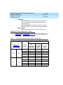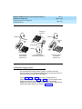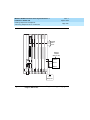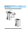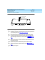
1
MERLIN LEGEND® Communications System Release 6.1 Installation 555-661-140 Comcode 108198029 Issue 1 August 1998 Copyright © 1998, Lucent Technologies 555-661-140 All Rights Reserved Printed in USA Copyright © 1998, Lucent Technologies Issue 1 August 1998 555-661-140 All Rights Reserved Printed in USA Issue 1 August 1998 Notice Every effort was made to ensure that the information in this book was complete and accurate at the time of printing. However, information is subject to change. See Appendix A, “Customer Support Information,” for important information. It follows Maintenance and Troubleshooting in this binder. Your Responsibility for Your System’s Security Toll fraud is the unauthorized use of your telecommunications system by an unauthorized party, for example, persons other than your company’s employees, agents, subcontractors, or persons working on your company’s behalf. Note that there may be a risk of toll fraud associated with your telecommunications system, and if toll fraud occurs, it can result in substantial additional charges for your telecommunications services. You and your system manager are responsible for the security of your system, such as programming and configuring your equipment to prevent unauthorized use. The system manager is also responsible for reading all installation, instruction, and system administration documents provided with this product in order to fully understand the features that can introduce risk of toll fraud and the steps that can be taken to reduce that risk. Lucent Technologies does not warrant that this product is immune from or will prevent unauthorized use of common-carrier telecommunication services or facilities accessed through or connected to it. Lucent Technologies will not be responsible for any charges that result from such unauthorized use. For Trademarks 5ESS, ACCUNET, ACCULINK, CONVERSANT, DEFINITY, Magic On Hold, Megacom, MERLIN, MERLIN II, MERLIN LEGEND, MERLIN MAIL, MultiQuest, Music on Hold, PassageWay, MLX-5, MLX-5D, MLX-10, MLX-10D, MLX-10DP, MLX16DP, MLX-20L, MLX-28D and Systimax are registered trademarks and 4ESS, Lucent Technologies Attendant, AUDIX Voice Power, FAX Attendant System, HackerTracker, MERLIN Identifier, ProLogix, are trademarks of Lucent Technologies in the US and other countries. Microsoft and Windows are registered trademarks of Microsoft Corporation. ProComm and ProComm Plus are registered trademarks of DataStorm Technologies, Inc. Supra, StarSet, and Mirage are registered trademarks of Plantronics, Inc. UNIX is a registered trademark of UNIX System Laboratories, Inc. PagePac is a registered trademark of DRACON, a division of Harris Corporation. Okidata is a registered trademark of Okidata Corporation. NORTEL is a registered trademark and DMS a trademark of Northern Telecom. MCI, Prism, and Vnet are registered trademarks of MCI Communications Corporation. Ordering Information Call: BCS Publications Center Voice 1 800 457-1235 Fax 1 800 457-1764 Write: BCS Publications Center 2855 North Franklin Road Indianapolis, IN 462191385 International Voice 317 322-6791 International Fax 317 322-6699 Issue 1 August 1998 MERLIN LEGEND Communications System Release 6.1 Installation 555-661-140 Contents Page v Contents New Features and Enhancements ■ Release 6.1 Enhancements (August 1998) xxiii xxiii Prior Releases Features and Enhancements xxix ■ Release 6.0 Enhancements (February, 1998) xxix ■ Release 5.0 Enhancements (June, 1997) xxxiv ■ Release 4.2 Enhancements (June, 1997) xl ■ Release 4.1 Enhancements (June, 1997) xliv ■ Release 4.0 Enhancements (March, 1996) xlvi ■ Release 3.1 Enhancements (March, 1996) l About This Book liii ■ Intended Audience liii ■ How to Use This Book liii ■ Terms and Conventions Used liv ■ Product Safety Advisories lvi ■ Security lvii ■ Related Documents lviii ■ How to Comment on This Document lix Issue 1 August 1998 MERLIN LEGEND Communications System Release 6.1 Installation 555-661-140 Contents Page vi 1 2 Introduction 1-1 ■ Installation Sequence 1-1 ■ System Forms 1-2 ■ Programming the System 1-4 ■ Upgrading the System 1-4 Installing the Control Unit 2-1 ■ Overview 2-1 ■ AC Power and Grounding 2-6 ■ Unit Loads 2-17 ■ Installing the Basic Carrier 2-18 ■ Installing the Power Supply 2-20 ■ Installing the Auxiliary Power Unit 2-26 ■ Installing Expansion Carriers 2-28 ■ Installing the Processor 2-30 ■ Installing the Modules 2-33 ■ Replacing a Module 2-41 ■ Connecting the Control Unit to an AC Outlet 2-44 ■ Powering Up the System 2-45 ■ Powering Down the System 2-46 Issue 1 August 1998 MERLIN LEGEND Communications System Release 6.1 Installation 555-661-140 Contents Page vii 3 4 5 Installing Telephones and Adjuncts 3-1 ■ Installing Multi-Function Modules ■ Installing Adjuncts 3-22 ■ Installing Direct Station Selectors 3-43 ■ Assembling MLX Telephones 3-48 ■ Installing Cordless or Cordless/Wireless Telephones 3-57 ■ Connecting Telephones to the Control Unit 3-58 Connecting the Control Unit to the Network Interface 3-2 4-1 ■ Wiring 4-2 ■ Testing Trunks 4-13 ■ Labeling Trunks 4-15 ■ Installing the Channel Service Unit 4-16 ■ Wiring Two Switches Together 4-19 Installing the PC, CAT, or Printer 5-1 ■ Connecting a PC to the Control Unit 5-1 ■ Connecting a CAT to the Control Unit 5-7 Connecting a Printer to the Control Unit 5-7 ■ Issue 1 August 1998 MERLIN LEGEND Communications System Release 6.1 Installation 555-661-140 Contents Page viii 6 7 8 Connecting Data Equipment 6-1 ■ Data Stations 6-1 ■ Analog Voice and Modem Data Stations 6-5 ■ Modem Data-Only Stations 6-8 ■ MLX Voice and Modem Data Stations 6-10 ■ MLX Voice and Terminal Adapter Data Stations 6-12 ■ Terminal Adapter Data-Only Stations 6-14 ■ Video Conferencing Data Stations 6-17 Initializing and Testing the System 7-1 ■ Initializing the System 7-1 ■ Setting the Time and Date 7-3 ■ Testing the System 7-3 ■ Installing the Control Unit’s Housing Installing Applications 7-22 8-1 ■ Voice Messaging Systems and Touch-Tone Receivers 8-3 ■ Automated Document Delivery System 8-4 ■ Call Accounting System 8-5 ■ Call Accounting Terminal 8-8 ■ Call Management System 8-10 ■ CONVERSANT 8-13 Issue 1 August 1998 MERLIN LEGEND Communications System Release 6.1 Installation 555-661-140 Contents Page ix ■ Integrated Solution III 8-14 ■ Lucent Technologies Attendant 8-17 ■ * MERLIN MAIL 8-19 ■ MERLIN PFC† 8-22 PassageWay Direct Connect Solution 8-24 ■ System Programming and Maintenance (SPM) 8-26 ■ Installing a CTI Link 8-28 Upgrading the System 9-1 ■ 9 ■ Upgrading to Release 6.1 9-2 ■ Backing Up System Programming 9-4 ■ Removing the Control Unit Housing 9-5 ■ Powering Down the System 9-7 ■ Upgrading the Control Unit 9-9 ■ Modifying the Processor for Key Mode 9-14 ■ Completing the Upgrade 9-18 ■ Upgrading from the MERLIN II Communications System 9-18 Replacing the Control Unit Housing 9-20 ■ Issue 1 August 1998 MERLIN LEGEND Communications System Release 6.1 Installation 555-661-140 Contents Page x A System Numbering Forms A-1 Form 2a, System Numbering: Extension Jacks A-2 Form 2b, System Numbering: Digital Adjuncts A-4 ■ Form 2c, System Numbering: Line/Trunk Jacks A-5 ■ Form 2d, System Numbering: Special Renumbers A-6 ■ ■ B Unit Load Calculation Worksheet ■ Unit Load Worksheet IN Index B-1 B-2 IN-1 MERLIN LEGEND Communications System Release 6.1 Installation 555-661-140 Issue 1 August 1998 Figures Page xi Figures 2 3 Installing the Control Unit 2-1 AC Grounding Requirements 2-7 2-2 Measuring the AC Outlet Voltages 2-10 2-3 Central Office and AC Grounds 2-12 2-4 Installing 146A and 147A Protectors 2-16 2-5 Marking the Basic Carrier Screw Holes 2-19 2-6 Installing a Copper Shield in the Power Supply 2-23 2-7 Installing the Ferrite Cores 2-25 2-8 Installing an Auxiliary Power Unit 2-27 2-9 Connecting the Carriers 2-29 2-10 Installing the Processor into the Carrier 2-32 2-11 400EM Module Sample Dip Switch Settings for Signaling Types 1C and 5 2-38 2-12 Line/Trunk and Telephone Jack Locations on Each Module 2-40 2-13 Removing Modules from the Carrier 2-43 Installing Telephones and Adjuncts 3-1 Multi-Function Module Packing List 3-3 3-2 Removing the User Card Tray and Line Cable 3-4 3-3 Releasing the Deskstand 3-5 3-4 Removing the Deskstand 3-6 3-5 Releasing the Module Cover Screw 3-7 3-6 Releasing the Module Cover 3-8 3-7 Removing the Module Cover 3-9 3-8 Removing an MFM Module 3-10 MERLIN LEGEND Communications System Release 6.1 Installation 555-661-140 Issue 1 August 1998 Figures Page xii 3-9 Installing an MFM Module 3-11 3-10 Setting and Adjusting the MFM Jumpers 3-12 3-11 Removing the Jack Guard 3-13 3-12 Placing the Module Cover into the Locating Slot 3-14 3-13 Lowering and Locking the Module Cover 3-15 3-14 Replacing and Tightening the Module Cover Screw 3-16 3-15 Replacing the Deskstand 3-17 3-16 Lowering the Deskstand and Locking into Place 3-18 3-17 Replacing the User Card Tray and Line Cable 3-19 3-18 Adjusting the Deskstand Height 3-20 3-19 Powering Up the Telephone after Installing the MFM 3-21 3-20 Routing the Cord(s) Through the Cord Channel 3-23 3-21 Manual and One-Touch Headset Operation 3-29 3-22 Single-Zone Paging with PagePac Plus 3-31 3-23 Single-Zone Paging with Customer-Supplied Amplifier 3-32 3-24 Single-Zone Paging with UPAM 3-33 3-25 Single-Zone Paging with Background Music and Magic on Hold 3-36 3-26 Multizone Paging with Background Music, Magic on Hold, and Bidirectional Paging (Talk-Back) 3-37 3-27 Installing the Supplemental Alert Adapter 3-39 3-28 Connecting One or More DSSs 3-45 3-29 Wiring for Auxiliary Power 3-46 3-30 Adjusting or Removing the Deskstand 3-49 3-31 Connecting the Line Cords 3-50 3-32 Removing the Extension Label 3-51 3-33 Labeling the Extension 3-52 3-34 Removing the Handset Holder 3-53 3-35 Rotating the Handset Holder 3-53 3-36 Replacing the Extension Label 3-54 3-37 Mounting the Backplate 3-55 3-38 Routing the Cord Through the Backplate 3-56 MERLIN LEGEND Communications System Release 6.1 Installation 555-661-140 Issue 1 August 1998 Figures Page xiii 4 5 3-39 Connecting Two Voice Pairs to a Telephone Using a Bridging Adapter (BR-241-B1) 3-62 3-40 Removing the Connecting Block 3-64 Connecting the Control Unit to the Network Interface 4-1 RJ21X Network Interface Connector 4-6 4-2 RJ21X Wiring Field Hardware 4-7 4-3 RJ21X Wiring Field Tools 4-8 4-4 Using the D-Impact Tool to Seat the Conductors 4-9 4-5 RJ11 and RJ14 Interfaces 4-11 4-6 3150 Front Panel 4-18 4-7 3150 Back Panel 4-19 4-8 DEFINITY ECS or DEFINITY ProLogix to MERLIN LEGEND T1 Tie Direct Connection on same continuous property 4-20 4-9 MERLIN LEGEND to MERLIN LEGEND T1 Tie Direct Connection on the same continuous property 4-21 Installing the PC, CAT, or Printer 5-1 Connecting a PC Within 50 ft. (15.2 m) 5-3 5-2 Connecting a PC More Than 50 ft. (15.2 m) Away 5-6 5-3 Connecting a CAT and Printer on the Same AC Outlet 5-10 5-4 Connecting a CAT and Printer on Different AC Outlets: Control Unit Connections 5-13 5-5 Connecting a Printer Within 50 ft. (15.2 m) 5-16 5-6 Connecting a Printer More Than 50 ft. (15.2 m) Away 5-19 5-7 Connecting the 248B Adapter and the 2012D Transformer 5-20 MERLIN LEGEND Communications System Release 6.1 Installation 555-661-140 Issue 1 August 1998 Figures Page xiv 6 7 9 Connecting Data Equipment 6-1 Analog Voice and Modem Data Equipment Configuration 6-7 6-2 Modem Data-Only Equipment Configuration 6-3 Modem Data and MLX Voice Equipment Configuration 6-4 MLX Voice and Terminal Adapter Data Equipment Configuration 6-13 6-5 Terminal Adapter Data-Only Equipment Configuration 6-16 6-6 Video Conferencing Configuration 6-19 6-9 6-10 Initializing and Testing the System 7-1 Ground-Start Button 7-20 7-2 Installing the Control Unit Top Cover 7-23 7-3 Installing the Control Unit Front Cover 7-24 Upgrading the System 9-1 Removing the Control Unit Housing 9-6 9-2 Powering Down the System 9-8 9-3 Removing a Module from the Carrier 9-11 9-4 Replacing a Module in the Carrier 9-13 9-5 Removing the Processor Module Cover 9-15 9-6 Removing the Processor Module Circuit Board 9-16 9-7 Changing the Key Mode Switch Position to Closed 9-17 9-8 Installing the Control Unit Housing 9-21 MERLIN LEGEND Communications System Release 6.1 Installation 555-661-140 Issue 1 August 1998 Figures Page xv A System Numbering Forms A-1 Form 2a, System Numbering: Extension Jacks A-2 A-2 Form 2b, System Numbering: Digital Adjuncts A-4 A-3 Form 2c, System Numbering: Line/Trunk Jacks A-5 A-4 Form 2d, System Numbering: Special Renumbers A-6 MERLIN LEGEND Communications System Release 6.1 Installation 555-661-140 Issue 1 August 1998 Figures Page xvi MERLIN LEGEND Communications System Release 6.1 Installation 555-661-140 Issue 1 August 1998 Tables Page xvii Tables 2 Installing the Control Unit 2-1 3 Environmental Requirements 2-2 AC Power Requirements 2-8 2-3 Heavy Lightning Protection 2-15 2-4 Setting the 400EM (Tie Trunk) Module DIP Switches 2-36 2-5 Signaling Formats for the 400EM (Tie Trunk) Module 2-37 Installing Telephones and Adjuncts 3-1 Unsupported Telephones and Adjuncts 3-40 3-2 Single-Line Telephones 3-41 3-3 Single-Line Telephones Supported by Release 3.0 and Later 4 5 2-2 3-42 Connecting the Control Unit to the Network Interface 4-1 Network Interfaces 4-3 4-2 Central Office Network Interface Codes 4-4 Installing the PC, CAT, or Printer 5-1 Lucent Technologies 572 Printer Options 5-2 Lucent Technologies 475/476 Printer DIP Switch 5-3 5-22 Settings 5-24 Lucent Technologies Printer DIP Switch Settings 5-25 MERLIN LEGEND Communications System Release 6.1 Installation 555-661-140 Issue 1 August 1998 Tables Page xviii 6 8 Connecting Data Equipment 6-1 Data Station Configurations 6-2 Terminal Adapter Settings 6-2 6-21 Installing Applications 8-1 TTRs Required by VMS 8-2 MERLIN MAIL Ports Required 8-4 8-20 MERLIN LEGEND Communications System Release 6.1 Installation 555-661-140 Issue 1 August 1998 Page xix The exclamation point in an equilateral triangle is intended to alert the user to the presence of important operating and maintenance (servicing) instructions in the literature accompanying the product. IMPORTANT SAFETY INSTRUCTIONS When installing telephone equipment, always follow basic safety precautions to reduce the risk of fire, electrical shock, and injury to persons, including: ■ Read and understand all instructions. ■ Follow all warnings and instructions marked on or packed with the product. ■ Never install telephone wiring during a lightning storm. ■ Never install a telephone jack in a wet location unless the jack is specifically designed for wet locations. ■ Never touch uninsulated telephone wires or terminals unless the telephone wiring has been disconnected at the network interface. ■ Use caution when installing or modifying telephone lines. ■ Use only Lucent Technologies-manufactured MERLIN LEGEND® Communications System circuit modules, carrier assemblies, and power units in the MERLIN LEGEND Communications System control unit. ■ Use only Lucent Technologies-recommended/approved MERLIN LEGEND Communications System accessories. ■ If equipment connected to the analog extension modules (008, 408, 408 GS/LS) or to the MLX telephone modules (008 MLX, 408 GS/LS-MLX) is to be used for in-range out-of-building (IROB) applications, IROB protectors are required. ■ Do not install this product near water, for example, in a wet basement location. MERLIN LEGEND Communications System Release 6.1 Installation 555-661-140 Issue 1 August 1998 Page xx ■ Do not overload wall outlets, as this can result in the risk of fire or electrical shock. ■ The MERLIN LEGEND Communications System is equipped with a 3-wire grounding-type plug with a third (grounding) pin. This plug will fit only into a grounding-type power outlet. This is a safety feature. If you are unable to insert the plug into the outlet, contact an electrician to replace the obsolete outlet. Do not defeat the safety purpose of the grounding plug. ■ The MERLIN LEGEND Communications System requires a supplementary ground. ■ Do not attach the power supply cord to building surfaces. Do not allow anything to rest on the power cord. Do not locate this product where the cord will be abused by persons walking on it. ■ Slots and openings in the module housings are provided for ventilation. To protect this equipment from overheating, do not block these openings. ■ Never push objects of any kind into this product through module openings or expansion slots, as they may touch dangerous voltage points or short out parts, which could result in a risk of fire or electrical shock. Never spill liquid of any kind on this product. ■ Unplug the product from the wall outlet before cleaning. Use a damp cloth for cleaning. Do not use cleaners or aerosol cleaners. ■ Auxiliary equipment includes answering machines, alerts, modems, and fax machines. To connect one of these devices, you must first have a Multi-Function Module (MFM). ■ Do not operate telephones if chemical gas leakage is suspected in the area. Use telephones located in some other safe area to report the trouble. MERLIN LEGEND Communications System Release 6.1 Installation 555-661-140 Issue 1 August 1998 Page xxi ! ! WARNING: ■ For your personal safety, DO NOT install an MFM yourself. ■ ONLY an authorized technician or dealer representative shall install, set options, or repair an MFM. ■ To eliminate the risk of personal injury due to electrical shock, DO NOT attempt to install or remove an MFM from your MLX telephone. Opening or removing the module cover of your telephone may expose you to dangerous voltages. SAVE THESE INSTRUCTIONS MERLIN LEGEND Communications System Release 6.1 Installation 555-661-140 Issue 1 August 1998 Page xxii MERLIN LEGEND Communications System Release 6.1 Installation 555-661-140 New Features and Enhancements Release 6.1 Enhancements (August 1998) Issue 1 Issue 1 August 1998 August 1998 Page xxiii New Features and Enhancements Release 6.1 Enhancements (August 1998) Release 6.1 includes all Release 6.0 functionality, plus the enhancements listed below. Private Networking Release 6.1 enhances the functioning of the networked MERLIN LEGEND Communications System in a number of ways: ■ Centralized Voice Messaging ■ Group Calling Enhancements ■ Transfer Redirect ■ Direct Station Selector ■ Call Forwarding ■ SMDR ■ Decrease in Call Set-Up Time ■ PRI Switch Type Test MERLIN LEGEND Communications System Release 6.1 Installation 555-661-140 New Features and Enhancements Release 6.1 Enhancements (August 1998) Issue 1 August 1998 Page xxiv Centralized Voice Messaging One or more MERLIN LEGEND systems (Release 6.1 or later) can share the voice messaging system (VMS) of another MERLIN LEGEND system, provided the systems are directly connected to the system with the VMS. In this configuration, the system containing the VMS is known as the hub. This sharing of the VMS is called “Centralized Voice Messaging.” Centralized Voice Messaging includes the functions of voice mail, Automated Attendant, and fax messaging. See the Network Reference for detailed information about Centralized Voice Messaging. Centralized Voice Messaging offers the following benefits: ■ Private-networked MERLIN LEGEND systems do not need a local VMS. Having systems use a centralized VMS instead of separate VMSs is more economical. ■ Users that travel between sites can dial the same digits anywhere in the private network to access the voice messaging system. For example, a salesperson headquartered in Cincinnati can dial the same four digits at the company’s Los Angeles office to retrieve voice messages. ■ Productivity is enhanced because messages can be forwarded and broadcasted to all personnel within the private network. ■ Calling groups on networked systems can send overflow coverage to a shared VMS, so that an incoming caller can leave a message instead of waiting in a queue. ■ The VMS can light the Message Waiting lights on multiple MERLIN LEGEND systems in a private network. This greater efficiency saves time because a user only has to look at his or her telephone to determine if he or she has a message. Group Calling Enhancements A calling group can have a single non-local member that is defined by the Uniform Dial Plan and exists on another MERLIN LEGEND Communications System connected by a tandem trunk to the local system. If a calling group contains a non-local member, the non-local member must be the only member in the calling group. See the Network Reference for details. MERLIN LEGEND Communications System Release 6.1 Installation 555-661-140 New Features and Enhancements Release 6.1 Enhancements (August 1998) Issue 1 August 1998 Page xxv A calling group containing a single non-local member can be used for the same purposes as a calling group containing local extensions, including: ■ Night Service. Night Service coverage can be provided across a private network to a centralized Automated Attendant, a non-local calling group, a QCC queue, a DLC, or any individual extension on the remote system, such as a night bell. ■ Group Coverage. Group Coverage can be provided across a private network to a VMS, a non-local calling group, a QCC queue, a DLC, or any individual extension on the remote system. ■ Calling group overflow coverage. Calling group overflow coverage can be provided by a centralized VMS, a non-local calling group, a QCC queue, a DLC, or any individual extension on the remote system. ■ Calls directed to another system. Lines connected to remote systems can be answered by any extension programmed to answer the call, such as a centralized Automated Attendant or a system operator (QCC or DLC). Transfer Redirect When an Automated Attendant transfers a call to a non-local extension, the transferring MERLIN LEGEND system monitors the call to ensure that it is answered. If the non-local extension is not available or the call is not answered within the transfer redirect timeout period (fixed at 32 seconds), the call stops ringing at the non-local destination and is redirected to the extension on the same system as the Automated Attendant that is programmed to receive redirected calls. This redirect extension can be a QCC queue, a calling group, or an individual extension. Direct Station Selector Now users can press a Direct Station Selector (DSS) button for a non-local extension to make or transfer calls to that extension. However, no busy indication is displayed by the DSS for non-local extensions. MERLIN LEGEND Communications System Release 6.1 Installation 555-661-140 New Features and Enhancements Release 6.1 Enhancements (August 1998) Issue 1 August 1998 Page xxvi Call Forwarding The Forward feature now can be used to send calls to non-local extensions across the private network. SMDR In addition to SMDR options for non-network calls placed to and from the local system, system managers now can program SMDR to log incoming and outgoing UDP calls, or they can choose to log no UDP calls. The factory setting is to record all UDP calls. Customers who use a call accounting system may not want to fill the database with calls coming and going across the private network. These customers may choose not to log UDP calls. Decrease in Call Set-Up Time The set-up time for a call across a private network has been reduced by programming the number of UDP digits expected. PRI Switch Type Test A new maintenance test, the PRI Switch Type Test, has been created to allow Lucent Technologies technicians or authorized dealers to automatically determine if each end of the PRI tandem trunks has been programmed correctly. Service Observing Service Observing allows one extension to listen in on (observe) a call at another extension. A typical application of this feature is that of a Customer Service supervisor observing how a Customer Service representative handles calls. The Service Observing group can consist of from one extension to all extensions in the system, including other Service Observers. Up to 16 Service MERLIN LEGEND Communications System Release 6.1 Installation 555-661-140 New Features and Enhancements Release 6.1 Enhancements (August 1998) Issue 1 August 1998 Page xxvii Observing groups can be programmed. The Service Observer and the observed extension must be on the same system. The observer activates Service Observing either by pressing a Service Observing button and then dialing an extension number or by pressing a DSS or Auto Intercom button. The Service Observer must use an MLX telephone to observe an extension; the telephone at the observed extension can be of any type. A warning tone that alerts the observer, the observed extension, and the caller that Service Observing is occurring can be set to On or Off through System Programming. The factory setting is On. Win SPM The System Programming and Maintenance (SPM) software is now available in a Windows format called Win SPM. For Release 6.1 and later systems, Win SPM provides a graphical user interface (GUI) for those tasks must commonly performed by the system manager. Pictorial representations of system components, such as modules and their vintages and the creation of MLX telephone button labels, appear on Win SPM. Win SPM also provides a DOS-emulator mode to program tasks not currently supported by the GUI and to program a MERLIN LEGEND system of Release 6.0 or earlier. Win SPM is available on CD-ROM and is supported in Windows 95, Windows NT, and Windows 98. Windows NT Driver Now available is the MERLIN LEGEND Windows NT PBX driver. When coupled with the CentreVu Telephony Services application, the driver provides true server-based Computer Telephony Integration (CTI). The new driver requires a MERLIN LEGEND system of Release 5.0 or later and servers and PCs that support the applications. MERLIN LEGEND Communications System Release 6.1 Installation 555-661-140 New Features and Enhancements Release 6.1 Enhancements (August 1998) Issue 1 August 1998 Page xxviii MERLIN LEGEND Communications System Release 6.1 Installation 555-661-140 Prior Releases Features and Enhancements Release 6.0 Enhancements (February, 1998) Issue 1 Issue 1 August 1998 August 1998 Page xxix Prior Releases Features and Enhancements Release 6.0 Enhancements (February, 1998) Release 6.0 includes all Release 5.0 functionality, plus the enhancements listed below. Private Networks In Hybrid/PBX mode systems only, MERLIN LEGEND Communications Systems can be networked with one another or with DEFINITY® Enterprise Communications Server (ECS) and ProLogix® Communications Systems in private networks. In previous releases, this functionality is available using tie lines, but users handle calls between networked switches as outside calls. In this release, dialing the pool access code is not necessary for a call going from one networked switch to another. Also, delay-start tie trunks or T1 trunks administered as PRI can act as tandem trunks to connect networked systems. Available for Hybrid/PBX mode systems, the private network features of the MERLIN LEGEND Communications System Release 6.0 provide the following advantages for geographically dispersed organizational sites: ■ Intersystem Calling. In a private network, users on one local system can call extensions on other systems in the network. Release 6.0 can support 2-, 3-, 4-, or 5-digit dial plans. They dial these extensions as inside calls. To implement this function, the system manager programs MERLIN LEGEND Communications System Release 6.1 Installation 555-661-140 Prior Releases Features and Enhancements Release 6.0 Enhancements (February, 1998) Issue 1 August 1998 Page xxx the extension ranges of remote networked switches to create a non-local dial plan. This programming does not actually affect numbering on the remote system. To correctly set up systems for transparent calling among non-local dial plan extensions, the system manager assigns networking tie and/or PRI tandem trunks to pools. Then he or she programs as many as 20 patterns, associates with routes, Facility Restriction Levels (FRLs), digit absorption, and digit prepending. This allows ARS-like routing of non-local dial plan calls. In addition, system managers can control whether calling name, calling number, or both are shown at MLX display telephone for incoming calls across PRI tandem trunks. ■ Toll Savings. Private networked trunks allow you to realize significant cost savings on toll calls by performing tandem switching in the following two ways: — Callers on a local system can reach the PSTN via outside trunks connected to other systems in a private network, avoiding toll charges or substantially decreasing the cost of toll calls. For example, if you are in Cincinnati and another site in your company is in Dallas, you can make a call to a number in the Dallas local calling area over your private network, decreasing toll costs. — In addition, organizations use private networked trunks to make calls between networked systems, which may be geographically distant from one another. Using the example above, from your office in Cincinnati you can dial an extension at a sister site in Dallas, just as you would dial an extension on your own local system, without a costly long-distance phone call. You simply dial the extension number. ■ Service Cost Savings. In addition to toll call savings, there are two other ways that organizations can save on service costs incurred from telecommunications providers that provide PSTN access: — You order a point-to-point T1 circuit from a service provider, then use system programming to set it up for tandem PRI services. As necessary, a service provider provides amplification for PRI tandem MERLIN LEGEND Communications System Release 6.1 Installation 555-661-140 Prior Releases Features and Enhancements Release 6.0 Enhancements (February, 1998) Issue 1 August 1998 Page xxxi trunks in cases where the distance between networked systems is great enough to distort signals, but the service provider does not supply switching services. — You can tailor your use of PRI B-channels with drop-and-insert equipment that allows fractional use of T1 channels for non-MERLIN LEGEND data/video communications between sites, while keeping the remaining T1 channels for PRI voice or data traffic. NOTE: The 24th T1 channel must not be dropped before reaching the MERLIN LEGEND Communications System because MERLIN LEGEND uses the 24th channel as the PRI D-channel or signalling channel. — You can tailor your use of T1 channels to support a mix of T1-emulated tandem tie trunks for voice or data communications at 56 kbps per channel, allowing 2B data transfers at 112 kbps. The system also allows fractional use of point-to-point T1 tandem trunks with drop-and-insert equipment. ■ Voice Mail and Auto Attendant. Networked systems should have their own local voice mail and/or auto attendant applications as well as their own external alerts and Music On Hold sources. However, a single auto attendant can transfer calls throughout the network. It can answer only those calls that arrive on the PSTN facilities of the system where it is connected. Chapter 1 in Network Reference includes an example of this configuration. Although many features are available using tie trunks for network connectivity, PRI tandem trunks provide greatly enhanced features and faster call setup. For this reason, PRI is recommended over tie functionality in private networks. Group Calling Enhancements Release 6.0 and later systems include Group Calling features that enhance group calling operations. MERLIN LEGEND Communications System Release 6.1 Installation 555-661-140 Prior Releases Features and Enhancements Release 6.0 Enhancements (February, 1998) Issue 1 August 1998 Page xxxii Queue Control The system manager can control the maximum number of calls allowed in the primary calling group queue for calls that arrive on certain facilities often assigned to calling groups. When the number of calls in queue reaches the programmed maximum, subsequent callers receive a busy signal. Queue control applies to calls received on the following types of facilities: ■ DID (Direct Inward Dialing) ■ PRI facilities programmed for dial-plan routing ■ All calls transferred from a VMI (voice messaging interface) port ■ Dial-in Tie Queue control also applies to internal calls to a Calling group and calls to a calling group through the QCC. Internal calls that dial a Listed Directory Number (LDN) or and are directed to a calling group administered as Position-Busy Backup are eligible for queue control. Calls that come in on a trunk assigned to the Queued Call Console (QCC) are not eligible for queue control if the call is directed to a calling group designated as Position-Busy Backup. Remote-access calls to a calling group, coverage calls directed to a calling group, calls directed to calling group through QCC Position-Busy backup, and all other outside calls are not eligible for queue control. Prompt-Based Overflow System managers can activate the Prompt-Based Overflow option. This option allows callers waiting in queue and listening to a delay announcement to press the # key in order to reach the overflow receiver for the group, which may be the QCC queue or another calling group (including a calling group assigned for a voice mail system). All three overflow distribution options—based on the number of calls, the time a caller has waited, and according to the caller’s prompt—may be used at one MERLIN LEGEND Communications System Release 6.1 Installation 555-661-140 Prior Releases Features and Enhancements Release 6.0 Enhancements (February, 1998) Issue 1 August 1998 Page xxxiii time. In this case, time-based and number-of-calls based options take precedence over overflow distribution based on the caller’s prompt. When prompt-based overflow distribution is used, an extra TTR must be provided for each delay announcement device assigned to the associated calling group. The delay announcement informs the caller of the # key option to exit the queue and leave rather than waiting for an agent. If no TTR is available when a calling group call arrives, the call is not sent to a delay announcement extension. Centrex Transfer via Remote Call Forwarding Centrex Transfer via Remote Call Forwarding can be used in all system modes of operation to send outside calls to a remote telephone number or another Centrex station. In this context, the term outside refers to calls that arrive on an analog Centrex loop-start line at the MERLIN LEGEND Communications System. An outside call that uses this feature is defined as a call that arrives on an analog Centrex loop-start line at the MERLIN LEGEND Communications System. It may arrive directly or be transferred without consultation or without transfer supervision (in the case of an automated attendant). The forwarding call to the outside number is made on the same line/trunk on which the call arrived, conserving system facilities. Activating Centrex Transfer via Remote Call Forwarding is just like activating regular Remote Call Forwarding and requires that Remote Call Forwarding be enabled for the extension. However, the user dials instead of a dial-out code, and a Pause character may be required after the . The Centrex service provider determines whether the Pause is needed. Pause cannot be originated from a single-line telephone or a remote access user. A multiline telephone user in the local system must enter an authorization code to activate the feature. A remote access user may activate the feature without using an authorization code. Barrier code requirements do apply, however. MERLIN LEGEND Communications System Release 6.1 Installation 555-661-140 Prior Releases Features and Enhancements Release 5.0 Enhancements (June, 1997) Issue 1 August 1998 Page xxxiv Authorization Codes and Remote Call Forwarding In Release 6.0 and later Key or Hybrid/PBX mode systems, forwarding features, including Centrex Transfer via Remote Call Forwarding, but excluding Follow Me, can be activated or deactivated at a multiline telephone by entering the authorization code for the extension from which calls are to be forwarded. The user enters the authorization code, then activates or deactivates the forwarding feature in the normal fashion. This is especially useful for a single-line telephone user who must include a Pause character in a Centrex Transfer via Remote Call Forwarding dialing sequence, because the character cannot be dialed at a single-line telephone. It is also useful when activating Call Forwarding or Remote Call Forwarding at phantom stations, or via remote access (e.g. from another switch in the network). No other features can be used by entering an authorization code in this fashion. Release 5.0 Enhancements (June, 1997) Release 5.0 includes all Release 4.2 functionality, plus the enhancements listed below. Computer Telephony Integration (CTI) Beginning with Release 5.0, a PassageWay® Telephony Services CTI link from the MERLIN LEGEND Communications System to a LAN server running Novell® NetWare® software allows Lucent Technologies-certified telephony applications to control and monitor MLX and analog multiline telephone (BIS only) operations. The physical connection for the CTI link is an MLX port on a 008 MLX or 408 MLX module on the MERLIN LEGEND Communications System control unit and ISDN link interface card plugged into the customer’s server. The feature is available for Hybrid/PBX mode systems only. NOTE: The NetWare server software version must be 3.12, 4.1 or 4.11. MERLIN LEGEND Communications System Release 6.1 Installation 555-661-140 Prior Releases Features and Enhancements Release 5.0 Enhancements (June, 1997) Issue 1 August 1998 Page xxxv The 008 MLX and 408 MLX modules must have firmware vintage other than 29. If the module has firmware 29, programming a CTI link on the module is prevented. An earlier or later vintage firmware is supported. Basic Call Control A CTI link application on a user’s computer can assume basic call control of the user’s analog multiline or MLX telephone’s SA buttons. Basic call control includes: ■ Answering calls arriving on an SA button ■ Making calls from an SA button ■ Hanging up calls ■ Hold and retrieving a call on hold at the user’s extension NOTE: Transfer and 3-way conference, when handled through a CTI link application, provide the original caller’s calling number information or other information to the transfer receiver or new conference participant, if the user has screen-pop capability. Screen Pop Screen pop occurs when the calling number, called number, or other user-defined identifier (such as account code that a voice-response unit prompts the caller to dial) is used to display a screen associated with the far-end party. For example, Caller ID services can be used to support screen pop on a system that includes a CTI link; using the calling party number as a database key code, information about a caller automatically appears on the user’s computer screen when the call arrives at the extension. Depending on the application, screen pop may be available for calls that arrive on line buttons other than SA buttons and/or calls that are answered manually at the telephone rather than by the application. Screen pop can occur on incoming calls from the following sources: MERLIN LEGEND Communications System Release 6.1 Installation 555-661-140 Prior Releases Features and Enhancements Release 5.0 Enhancements (June, 1997) Issue 1 August 1998 Page xxxvi ■ Calling group distribution ■ ISDN PRI Routing by Dial Plan ■ An extension on the MERLIN LEGEND Communications System ■ Remote access NOTE: In the case of remote access calls, the only information that the application can collect about the caller is the remote telephone number. ■ A transfer of a call that was answered by a voice response unit ■ A transfer, redirection, or conference of a call that was answered at a DLC or at a QCC 1. DLCs (Direct-Line Consoles) may use CTI applications. If they do, they perform the same way as other extensions. A DLC assigned to use a CTI link application is a monitored DLC. When a DLC is used as a regular operator console and not using a CTI link extension, it is non-monitored. 2. Calls to a QCC or non-monitored DLC do not initiate screen pop at the operator position, but when an operator directs a call to an extension using a CTI application, caller information does initiate screen pop. If the DLC is non-monitored, screen pops can occur after the DLC releases the call. 3. Calls transferred from Cover buttons on non-monitored DLCs do not initiate screen pop at the destination extension. HotLine Feature The Release 5.0 HotLine feature is designed for retail sales, catalogue sales, and other types of businesses and organizations and is available in all three modes of system operation. It allows a system manager to program a single-line telephone extension connected to an 008 OPT, 012, or 016 module as a HotLine. When a user lifts the handset at the HotLine extension, the telephone MERLIN LEGEND Communications System Release 6.1 Installation 555-661-140 Prior Releases Features and Enhancements Release 5.0 Enhancements (June, 1997) Issue 1 August 1998 Page xxxvii automatically dials the inside extension or outside telephone number programmed as the first Personal Speed Dial number (code #01) for the extension. The system does not permit calls to be transferred, put on hold, or conferenced. (A user can press the telephone’s Hold button, if it has one, to put a call on local hold, but the call cannot be redirected in any way. Switchhook flashes are ignored.) Personal Speed Dial codes can be programmed from the extension prior to HotLine assignment (a system programming function). Alternatively, a Personal Speed Dial code can be programmed from the single-line telephone after HotLine operation is assigned. However, because of security considerations, this is a one-time opportunity. Once the Personal Speed Dial number is programmed, any changes to it or any other extension programming must be performed using centralized telephone programming. Any type of inside or outside line that is normally available to a single-line telephone can be assigned to a HotLine extension. Generally, the HotLine telephone does not receive calls, and its lines should be set to No Ring. ! SECURITY ALERT: If a HotLine extension accesses a loop-start line, that line should provide reliable disconnect and be programmed for reliable disconnect. Otherwise, a user at the extension may be able to stay on the line after a call is completed and then make a toll call. Group Calling Enhancements Release 5.0 and later systems include Group Calling features that enhance group calling operations. Most Idle Hunt Type In addition to the Circular (factory setting) and Linear hunt types supported in earlier releases, a third hunt type distributes calling group calls in an order based on which agent has waited the longest since transferring or hanging up on an incoming calling group call. For some applications, this hunt type is more MERLIN LEGEND Communications System Release 6.1 Installation 555-661-140 Prior Releases Features and Enhancements Release 5.0 Enhancements (June, 1997) Issue 1 August 1998 Page xxxviii efficient than the circular type because it takes into account the varying duration of calls. The system distributes calls based on when an agent last completed a call, not on when he or she last received one. This hunting method ignores non-calling group calls. For example, if an agent transfers a call that arrived on a line not assigned to the calling group, the calling group member’s most-idle status is unaffected. Delay Announcement Devices The system manager can designate as many as ten primary delay announcement devices per group rather than the single device for each group that is available in Release 4.2 and earlier systems. Furthermore, an additional secondary delay announcement device can be specified, for a total of ten primary device extensions and one secondary device extension per group. A primary delay announcement device operates in the same fashion as a single delay announcement device, playing once, as soon as it is available, for the caller who has waited the longest for a calling group agent and has not heard a primary delay announcement. If a secondary announcement device is used, it can use the factory setting, which plays the announcement once, or it can be set to repeat the announcement after a certain amount of time. The system manager programs the time (0–900 seconds) between announcements. This setting controls both the interval between primary and secondary announcements and the interval between repetitions of the secondary announcement if it is set to repeat. (See Group Calling Options in Chapter 4 for guidelines on setting the delay.) The primary and secondary announcement options, when used together, allow an initial message to play for callers, followed by a repeating announcement that, for example, urges callers to stay on the line and wait for a calling group member. Two or more groups may share an announcement device. A primary delay announcement device can be administered as a secondary delay announcement device. MERLIN LEGEND Communications System Release 6.1 Installation 555-661-140 Prior Releases Features and Enhancements Release 5.0 Enhancements (June, 1997) Issue 1 August 1998 Page xxxix Enhanced Calls-in-Queue Alarm Thresholds Three Calls-in-Queue Alarm thresholds can be set to more clearly indicate the real-time status of the calls waiting in the queue according to the behavior of programmed Calls-in-Queue Alarm buttons. In earlier releases, only one Calls-in-Queue Alarm Threshold setting is available to activate the LEDs at programmed Calls-in-Queue Alarm buttons for a calling group. Using all three levels, the system manager sets Threshold 3 to the highest value, Threshold 2 to a middle value, and Threshold 1 to the lowest value. A Calls-in-Queue Alarm button indicates the severity of the alarm conditions in the following ways: ■ If the number of waiting calls is less than the value programmed for Threshold 1 or drops below that level, the LED is unlit. ■ If the number of waiting calls is greater than or equal to the Threshold 1 value but less than the Threshold 2 value, the LED flashes. ■ If the number of waiting calls is greater than or equal to the Threshold 2 value but less than the value for Threshold 3, the LED winks. ■ If the number of waiting calls is greater than or equal to the highest value, Threshold 3, the LED lights steadily. NOTE: A DSS (Direct Station Selector) button that is used as a Calls-in-Queue Alarm button can only indicate two threshold levels, either by flashing or by lighting steadily. If a calling group must use this type of Calls-in-Queue Alarm button, only two threshold levels should be programmed. If all three thresholds are set to the same value, the result is one threshold only with LED state either off or on (steady). If two values are the same, then the result is two alarm levels (flash, steady). The factory setting is one call for all three thresholds with LED states of off and steady. An external alert only signals when the number of calls in the queue meets or exceeds the programmed Threshold 3 value. MERLIN LEGEND Communications System Release 6.1 Installation 555-661-140 Prior Releases Features and Enhancements Release 4.2 Enhancements (June, 1997) Issue 1 August 1998 Page xl MLX-5 and MLX-5D Telephones The MLX-5 nondisplay and MLX-5D display telephones are compatible with all system releases. The display telephone includes a 2-line by 24-character display, and both telephones come with 5 line buttons. In systems prior to Release 5.0, the MLX-5 and MLX-5D telephones are treated as MLX-10 and MLX-10D telephones respectively. As of Release 5.0, the system recognizes the MLX-5 and MLX-5D telephones as 5-button telephones. If these telephones are connected to communications system releases prior to 5.0 they are recognized by the communications system as 10 button telephones. Release 4.2 Enhancements (June, 1997) Release 4.2 includes all Release 4.1 functionality, plus the enhancements listed below. There are no hardware changes for Release 4.2. Additional Network Switch and Services Options for ISDN Primary Rate Interface (PRI) Release 4.2 of the system supports connectivity to MCI® or local exchange carrier (LEC) PRI services and to the following central office switch types (in addition to the 4ESS™ and 5ESS® switch types that carry for AT&T Switched Network services): ■ NORTEL® DMS™-100 BCS 36 for local exchange carrier services ■ NORTEL DMS-250 generic MCI07 serving the MCI network ■ Digital Switch Corporation DEX600E generic 500-39.30 serving the MCI network Beginning with Release 4.2, the following MCI PRI and PRI local exchange carrier (LEC) services (along with AT&T Switched Network Services) can be provided to users of the MERLIN LEGEND Communications System: MERLIN LEGEND Communications System Release 6.1 Installation 555-661-140 Prior Releases Features and Enhancements Release 4.2 Enhancements (June, 1997) ■ Issue 1 August 1998 Page xli MCI Toll Services for DMS-250 or DEX600E switch type: — MCI Prism® service for domestic outgoing long-distance and international voice calls; for domestic outgoing 56-kbps restricted, 64-kbps unrestricted, and 64-kbps restricted circuit-switched data calls — MCI VNet® service for incoming and outgoing domestic and voice calls; for 56-kbps restricted, 64-kbps restricted, and 64-kbps unrestricted circuit-switched data calls — MCI 800 for domestic, toll-free, incoming voice calls — MCI 900 service numbers ■ LEC services for DMS-100 switch types: — DMS Virtual Private Network service for calls between the MERLIN LEGEND Communications System and another communications system (such as another MERLIN LEGEND Communications System) — DMS INWATS (Inward Wide Area Telephone Service) for domestic toll-free incoming voice calls — DMS OUTWATS (Outward Wide Area Telephone Service) for domestic outgoing long-distance voice calls — DMS FX (foreign exchange) to provide local call rating for calls from the local exchange to the area serviced by the foreign exchange. — DMS tie trunk service to provide private exchange call rating for calls placed on a dedicated central office facility between the MERLIN LEGEND Communications System and another communications system (such as another MERLIN LEGEND Communications System) MERLIN LEGEND Communications System Release 6.1 Installation 555-661-140 Prior Releases Features and Enhancements Release 4.2 Enhancements (June, 1997) Issue 1 August 1998 Page xlii Improvements to Station Message Detail Recording (SMDR) and Support for MERLIN LEGEND Reporter Application The SMDR feature is enhanced to provide more details about calling group agent activities and to help system managers assess the effectiveness of call centers in terms of both agent performance and the adequacy of facilities to handle inbound calls. These improvements apply to calling groups that are programmed as Auto Login or Auto Logout type. The SMDR and MERLIN LEGEND Reporter features listed are administrable: ■ TALK Field. For Auto Login and Auto Logout calling groups, the TALK field records the amount of time a calling group agent spends on a call. ■ DUR. (DURATION) Field. For Auto Login and Auto Logout calling groups, call timing begins when a call arrives at MERLIN LEGEND Communications System and not after a preset number of seconds. Call timing ends when the call is disconnected; either the caller or the agent hangs up. This allows the system manager to determine how long a caller waited for an agent’s attention. ■ Coding of Calls on Reports. An asterisk (*) appears in the call record when: a A call is not answered by an Auto Login or Auto Logout calling group agent and is abandoned while waiting for an agent. b The call is answered by someone not a member of an Auto Login or Auto Logout calling group. An exclamation point (!) signals that an Auto Login or Auto Logout agent handled a call that was answered by someone who was not a member of that Auto Login or Auto Logout with Overflow group. An ampersand (&) in the call record indicates that the group’s overflow receiver answered the call. MERLIN LEGEND Reporter MERLIN LEGEND Reporter provides basic call accounting system reports for all incoming calls to Auto Login or Auto Logout type calling groups. MERLIN MERLIN LEGEND Communications System Release 6.1 Installation 555-661-140 Prior Releases Features and Enhancements Release 4.2 Enhancements (June, 1997) Issue 1 August 1998 Page xliii LEGEND Reporter assists in determining the effectiveness of calling group agents, assessing the level of service provided to callers, and ascertaining whether adequate incoming phone lines and agents are available to handle peak-call load. The SMDR Talk Time option sets up special call records used by MERLIN LEGEND Reporter. The default is Off, in which case the Release 4.0 SMDR reports are available. If the option is set to On, the following new reports are provided: ■ Organization Detail Report ■ Organization Summary and Trends Report ■ Selection Detail Report ■ Account Code Report ■ Traffic Report ■ Extension Summary Report ■ Data Report ■ Talk and Queue Time Distribution Report ■ Time of Day Report ■ ICLID Call Distribution Report ■ Facility Grade of Service Report Maintenance Enhancements Change to Permanent Error Alarm Beginning with Release 4.2, the most recent permanent error alarm is not shown on the System Error Log menu screen but is available as an option from that screen. For details, refer to the Maintenance section of the technician guide, Installation, Programming, and Maintenance. MERLIN LEGEND Communications System Release 6.1 Installation 555-661-140 Prior Releases Features and Enhancements Release 4.1 Enhancements (June, 1997) Issue 1 August 1998 Page xliv Enhanced Extension Information Report Beginning with Release 4.2, the Extension Information Report includes the Extension Status (ESS) and supervisory mode of each extension. Release 4.1 Enhancements (June, 1997) Release 4.1 includes all Release 4.0 functionality, plus the enhancements listed below. There are no hardware changes in Release 4.1. Coverage Timers Programmed for Individual Extensions Beginning with Release 4.1, coverage timers, which control the duration of the delay before calls are sent to each level of coverage, are changed as follows: ■ The Group Coverage Ring Delay (1–9 rings) is programmed on individual extensions and replaces the Coverage Delay Interval programmed systemwide in previous releases. ■ The Primary Cover Ring Delay (1–6 rings) and Secondary Cover Ring Delay (1–6 rings), programmed on individual extensions, replace the Delay Ring Interval programmed systemwide in previous releases. These enhancements allow the system manager to customize coverage call delivery to match individual extensions’ call-handling requirements. Night Service with Coverage Control Beginning with Release 4.1, a system manager can enable the Night Service Coverage Control option to automatically control the status of telephones programmed with Coverage VMS (voice messaging system) Off buttons, according to Night Service status. MERLIN LEGEND Communications System Release 6.1 Installation 555-661-140 Prior Releases Features and Enhancements Release 4.1 Enhancements (June, 1997) Issue 1 August 1998 Page xlv When Coverage Control is enabled and the MERLIN LEGEND Communications System is put into Night Service, all programmed Coverage VMS Off buttons are automatically turned off (LED is unlit) and all eligible outside calls are sent to the assigned voice messaging system calling group with normal ringing delay. When Night Service is deactivated during the day, all programmed Coverage VMS Off buttons are automatically turned on (LED is lit) and voice mail coverage is disabled for outside calls. Users can override the Coverage VMS Off button status at any time by pressing the programmed Coverage VMS Off button to turn the LED on or off. Night Service Group Line Assignment Beginning with Release 4.1, a system manager can assign lines to Night Service groups to control handling of after-hours calls received on individual lines. This capability replaces the automatic assignment to Night Service groups of only those lines that ring on the Night Service operator console. An outside line must be assigned to a Night Service group to receive Night Service treatment. With this enhancement, Night Service can be activated and deactivated on lines that do not appear on operator consoles (for example, personal lines), and lines appearing at operator positions can be excluded from Night Service. Forward on Busy Beginning with Release 4.1, the Forward, Follow Me, and Remote Call Forward features are enhanced to remove the requirement that a call be ringing at an extension before it can be forwarded. With the Forward on Busy enhancement, a call to an extension with no available SA (System Access) or ICOM (Intercom) buttons is forwarded immediately to the programmed destination, preventing the caller from hearing a busy signal from the intended call recipient’s extension. MERLIN LEGEND Communications System Release 6.1 Installation 555-661-140 Prior Releases Features and Enhancements Release 4.0 Enhancements (March, 1996) Issue 1 August 1998 Page xlvi Maintenance Testing for BRI Facilities that Are Part of Multiline Hunt Groups (MLHGs) Beginning with Release 4.1, the NI-1 BRI (National Integrated Services Digital Network-1 Basic Rate Interface) Provisioning Test Tool is enhanced to include testing for BRI facilities that are part of Multiline Hunt Groups (MLHGs). The NI-1 BRI Provisioning Test Tool is used by Lucent Technologies maintenance personnel on MERLIN LEGEND Communications Systems that include a 800 NI-BRI module. Technicians use the tool during system installation and maintenance to test the functionality of the BRI lines and to report analyzed results. Release 4.0 Enhancements (March, 1996) Release 4.0 includes all Release 3.1 functionality, plus the enhancements listed below. Support for Up to 200 Extensions An expanded dial plan supports up to 200 tip/ring devices. Support for National ISDN BRI Service This service (Hybrid/PBX and Key modes) provides an alternative to loop-start and ground-start lines/trunks for voice and digital data connectivity to the central office. Each of the two B-channels (bearer channels) on a BRI line can carry one voice and one data call at any given time. The data speeds on a B-channel are up to 28.8 kbps for analog data and up to 64 kbps for digital data, which is necessary for videoconferencing and other high-speed applications. Release 4.0 supports the IOC Package “S” (basic call handling) service configuration and Multiline Hunt service configuration on designated CO switches. MERLIN LEGEND Communications System Release 6.1 Installation 555-661-140 Prior Releases Features and Enhancements Release 4.0 Enhancements (March, 1996) Issue 1 August 1998 Page xlvii New Control Unit Modules Release 4.0 supports a new NI-BRI line/trunk module and a higher-capacity tip/ring module. 800 NI-BRI Module This new module connects NI-BRI trunks to the MERLIN LEGEND system for voice, high-speed data, and video transmission. 016 Tip/Ring Module This new module supports a 200-extension dial plan by providing 16 ports for tip/ring devices. Applications that use a tip/ring interface can connect to this board. All 16 ports can ring simultaneously. Four touch-tone receivers (TTRs) are included on the module as well. The module’s ringing frequency (default 20 Hz) can be changed through programming to 25 Hz for those locations that require it. Downloadable Firmware for the 016 and NI-BRI Modules The Personal Computer Memory Card International Association (PCMCIA) technology introduced in Release 3.0 continues to support these two new boards for installation and upgrade in Release 4.0. A Release 3.0 or later processor is required for PCMCIA technology. Support for 2B Data Applications A Lucent Technologies-certified group and desktop video application can use two B-channels to make video/data calls when connected to a single MLX extension jack programmed for 2B data. The 2B data devices must be equipped with ISDN-BRI interfaces. NI-1 BRI, PRI, or T1 Switched 56 facilities support 2B data communications at 112 kbps (using two 56-kpbs channels) or 128 kbps (using two 64-kbps B-channels). This feature is available for Hybrid/PBX and Key modes only. MERLIN LEGEND Communications System Release 6.1 Installation 555-661-140 Prior Releases Features and Enhancements Release 4.0 Enhancements (March, 1996) Issue 1 August 1998 Page xlviii Support for T1 Switched 56 Digital Data Transmission For Hybrid/PBX and Key mode systems, Release 4.0 expands support of T1 functionality by providing access to digital data over the public switched 56-kbps network, as well as to digital data tie-trunk services. Users who have T1 facilities for voice services can now use them for video or data calls at rates of 56 kbps per channel (112 kbps for video calls using 2B data). The Release 4.0 offering also includes point-to-point connectivity over T1 tie trunks, allowing customers to connect two MERLIN LEGEND Communications Systems or a MERLIN LEGEND Communications System with a Lucent Technologies DEFINITY® G1.1 Communications System or DEFINITY Enterprise Communications Server. The two communications systems can be co-located or at different sites. Forwarding Delay Option Each user can program a Forwarding Delay setting for the Forward, Remote Call Forwarding, or Follow Me features. The forwarding delay is the number of times that a call rings at the forwarding extension before the call is sent to the receiver. The delay period gives the original call recipient time to answer or to screen calls by checking the displayed calling number (if available). The delay can be set at 0 up to 9 rings. The factory setting for the forwarding delay is 0 rings (no delay). Voice Announce on Queued Call Console The system manager can enable the fifth Call button on a QCC console (Hybrid/PBX mode only) to announce a call on another user’s speakerphone (providing the destination telephone has a voice announce-capable SA button available). A QCC cannot receive voice-announced calls; they are received as ringing calls. The factory-set status for the fifth Call button is Voice Announce disabled. MERLIN LEGEND Communications System Release 6.1 Installation 555-661-140 Prior Releases Features and Enhancements Release 4.0 Enhancements (March, 1996) Issue 1 August 1998 Page xlix Time-Based Option for Overflow on Calling Group Release 4.0 has added a time limit for calls in queue in addition to the previous number of calls limit. If the Overflow Threshold Time option is set to a valid number between 1 and 900 seconds, calls that remain in the calling group queue for the set time are sent to the overflow receiver. If the overflow threshold time is set to 0, overflow by time is turned off. The factory-set time limit is 0 seconds (off). Single-Line Telephone Enhancements The following changes enhance the performance of single-line telephones: ■ Disable Transfer. Through centralized telephone programming, the system manager can disable transfer by removing all but one SA or ICOM button from the extension. ■ No Transfer Return. When a handset bounces in its cradle, the system interprets this as a switchhook flash and attempts to transfer a call. When the transfer attempt period expires, the user’s telephone rings. Release 4.0 eliminates this unintended ringing by disconnecting the call in situations where a switchhook flash is followed by an on-hook state and a dial tone is present. ■ Forward Disconnect. All ports on 008 OPT, 012, and 016 modules now send forward disconnect to all devices connected to them when forward disconnect is received from the CO. This enhancement prevents the trunk/line from being kept active when one end disconnects from the call. If an answering machine is connected to the port, it does not record silence, busy tones, or other useless messages. This operation is not programmable. Seven-Digit Password for SPM Release 4.0 has increased system security by requiring a 7-digit password for system managers or technicians who use SPM to perform programming or the MERLIN LEGEND Communications System Release 6.1 Installation 555-661-140 Prior Releases Features and Enhancements Release 3.1 Enhancements (March, 1996) Issue 1 August 1998 Page l Trunk Test procedure. This password is for use in addition to a remote access barrier code. Release 3.1 Enhancements (March, 1996) Release 3.1 includes all Release 3.0 functionality, plus the enhancements listed below. Call Restriction Checking for Star Codes Beginning with Release 3.1, a system manager can add star (*) codes to Allowed and Disallowed Lists to help prevent toll fraud. Star codes, typically dialed before an outgoing call, enable telephone users to obtain special services provided by the central office (CO). For example, in many areas, a telephone user can dial *67 before a telephone number to disable central office-supplied caller identification at the receiving party’s telephone. You must contract with your telephone service provider to have these codes activated. When users dial star codes, the system’s calling restrictions determine whether the codes are allowed. If they are allowed, the system’s calling restrictions are reset and the remaining digits that the users dial are checked against the calling restrictions. Trunk-to-Trunk Transfer Set for Each Extension This enhancement to the Transfer feature enables the system manager to allow or disallow trunk-to-trunk transfer on a per-extension basis. In Release 3.1 and later systems, the default setting for all extensions is restricted. Programmable Second Dial Tone Timer The system manager can assign a second dial tone timer to lines/trunks, in order to help prevent toll fraud (for example, when star codes are used). After MERLIN LEGEND Communications System Release 6.1 Installation 555-661-140 Prior Releases Features and Enhancements Release 3.1 Enhancements (March, 1996) Issue 1 August 1998 Page li receiving certain digits dialed by a user, the CO may provide a second dial tone, prompting the user to enter more digits. If this second dial tone is delayed, and the user dials digits before the CO provides the second dial tone, there is a risk of toll fraud or misrouting the call. The second dial tone timer enables the system manager to make sure that the CO is ready to receive more digits from the caller. Security Enhancements The sections below outside security measures that are implemented in Release 3.1 and later systems. Disallowed List Including Numbers Often Associated with Toll Fraud A factory-set Disallowed List 7 contains default entries, which are numbers frequently associated with toll fraud. By default, Disallowed List 7 is automatically assigned to both generic and integrated VMI (voice messaging interface) ports used by voice messaging systems. The system manager can manually assign this list to other extensions. Default Pool Dial-Out Code Restriction for All Extensions The default setting for the pool dial-out code restriction (Hybrid/PBX mode only) is restricted. No extension or remote access user with a barrier code has access to pools until the restriction is removed by the system manager. Default Outward Restrictions for VMI Ports Ports assigned for use by voice messaging systems (generic or integrated VMI ports) are now assigned outward restrictions by default. If a voice messaging system must be allowed to call out (for example, to send calls to a user’s home office), the system manager must remove these restrictions. MERLIN LEGEND Communications System Release 6.1 Installation 555-661-140 Prior Releases Features and Enhancements Release 3.1 Enhancements (March, 1996) Issue 1 August 1998 Page lii ! SECURITY ALERT: Before removing restrictions, it is strongly recommended that you read Appendix A, “Customer Support Information.” Default Facility Restriction Level (FRL) for VMI Ports The default Automatic Route Selection (ARS) FRL for VMI ports is 0, restricting all outcalling. Default for the Default Local Table The default Automatic Route Selection (ARS, Hybrid/PBX mode only) FRL has changed to 2 for the Default Local table. System managers can easily change an extension default of 3 to 2 or lower in order to restrict calling. No adjustment to the route FRL is required. New Maintenance Procedure for Testing Outgoing Trunks Technicians must enter a password in order to perform trunk tests. The enhancements in Release 3.1 help increase the security of the MERLIN LEGEND System. To fully utilize these security enhancements, be sure to read and understand the information in these upgrade notes and in the relevant system guides. MERLIN LEGEND Communications System Release 6.1 Installation 555-661-140 About This Book Intended Audience Issue 1 Issue 1 August 1998 August 1998 Page liii About This Book The MERLIN LEGEND Communications System is an advanced digital switching system that integrates voice and data communications features. Voice features include traditional telephone features, such as Transfer and Hold, and advanced features, such as Group Coverage and Park. Data features allow both voice and data to be transmitted over the same system wiring. Intended Audience This book provides detailed information about system and telephone trouble reports and troubleshooting operations. It is intended for use by qualified field technicians who are responsible for system installation maintenance and troubleshooting, and as a reference by anyone needing such information, including support personnel, sales representatives, and account executives. How to Use This Book This book provides step-by-step procedures for isolating troubles both inside and outside the communications system. Refer to the chapter associated with the reported problem to start the troubleshooting procedure. MERLIN LEGEND Communications System Release 6.1 Installation 555-661-140 About This Book Terms and Conventions Used Issue 1 August 1998 Page liv Refer to the following documentation for additional information: ■ Equipment and Operations Reference provides detailed information on system hardware, telephones, and other equipment. (Not updated since Release 3.0.) ■ Feature Reference provides details on the features of the communications system. ■ System Planning provides procedures and forms for planning and preparing a system for installation. ■ System Programming gives procedural instructions for programming system features. ■ User’s guides and Operator’s Guides give procedural instructions for programming and using telephone features. “Related Documents,” later in this section, provides a complete list of system documentation together with ordering information. In the USA only, Lucent Technologies provides a toll-free customer Helpline (1 800 628-2888) 24 hours a day. Call the Helpline, or your Lucent Technologies representative, if you need assistance when installing, programming, or using your system. Terms and Conventions Used In this document, the terms in the following list are used in preference to other, equally acceptable terms for describing communications systems. Lines, Trunks and Facilities Facility is a general term that designates a communications path between a telephone system and the telephone company central office. Technically a trunk connects a switch to a switch, for example the MERLIN LEGEND Communications System to the central office. Technically, a line is a loop-start facility or a communications path that does not connect two switches (for example, an intercom line or a MERLIN LEGEND Communications System Release 6.1 Installation 555-661-140 About This Book Terms and Conventions Used Issue 1 August 1998 Page lv Centrex line). However, in actual usage, the terms line and trunk are often applied interchangeably. In this book, we use line/trunk and lines/trunks to refer to facilities in general. Specifically, we refer to digital facilities. We also use terms such as personal line, ground-start trunk, Direct Inward Dialing (DID) trunk, and so on. When you talk to your local telephone company central office, ask them which terms they use for the specific facilities they connect to your system. Some older terms have been replaced with newer terms. The following list shows the old term on the left and the new term on the right: Old Term New Term trunk module line/trunk module trunk jack line/trunk jack station extension station jack extension jack analog data station modem data station digital data station terminal adapter 7500B data station terminal adapter analog voice and analog data station analog voice and modem data digital voice and analog data station MLX voice and modem data analog data-only station modem data only station digital data-only station terminal adapter only station 7500B data-only station terminal adapter only station digital voice and digital data station MLX voice and terminal adapter station MLX voice and 7500B data station MLX voice and terminal adapter station MERLIN LEGEND Communications System Release 6.1 Installation 555-661-140 About This Book Product Safety Advisories Issue 1 August 1998 Page lvi Typographical Conventions Certain type fonts and styles act as visual cues to help you rapidly understand the information presented: Example Purpose It is very important that you follow these steps. You must attach the wristband before touching the connection. Italics indicate emphasis. The part of the headset that fits over one or both ears is called a headpiece. Italics also set off special terms. If you press the Feature button on an MLX display telephone, the display lists telephone features you can select. A programmed Auto Dial button gives you instant access to an inside or outside number. The names of fixed-feature, factory-imprinted buttons appear in bold. The names of programmed buttons are printed as regular text. Choose ([W3URJ from the display screen. Plain constant-width type indicates text that appears on the telephone display or personal computer (PC) screen. To activate Call Waiting, dial . Constant-width type in italics indicates characters you dial at the telephone or type at the PC. Product Safety Advisories Throughout these documents, hazardous situations are indicated by an exclamation point inside a triangle and the word CAUTION or WARNING. MERLIN LEGEND Communications System Release 6.1 Installation 555-661-140 About This Book Security ! Issue 1 August 1998 Page lvii ! WARNING: Warning indicates the presence of a hazard that could cause death or severe personal injury if the hazard is not avoided. ! CAUTION: Caution indicates the presence of a hazard that could cause minor personal injury or property damage if the hazard is not avoided. Security Certain features of the system can be protected by passwords to prevent unauthorized users from abusing the system. You should assign passwords wherever you can and limit knowledge of such passwords to three or fewer people. Nondisplaying authorization codes and telephone numbers provide another layer of security. For more information, see Appendix A, “Customer Support Information” following Maintenance and Troubleshooting. Throughout this document, toll fraud security hazards are indicated by an exclamation point inside a triangle and the words Security Alert. ! Security Alert: Security Alert indicates the presence of atoll fraud security hazard. Toll fraud is the unauthorized use of your telecommunications system by an unauthorized party (for example, persons other than your company’s employees, agents, subcontractors, or persons working on your company’s behalf). Be sure to read “Your Responsibility for Your System’s Security” on the inside front cover of this book and “Security of Your System: Preventing Toll Fraud” in Appendix A, “Customer Support Information.” MERLIN LEGEND Communications System Release 6.1 Installation 555-661-140 About This Book Related Documents Issue 1 August 1998 Page lviii Related Documents In addition to this book, the documents listed below are part of the MERLIN LEGEND documentation set. Within the continental United States, these documents can be ordered from the Lucent Technologies BCS Publications Fulfillment Center by calling 1 800 457-1235. Document No. Title System Documents 555-661-100 Customer Documentation Package Consists of paper versions of System Manager’s Guide, Feature Reference, and System Programming. 555-661-110 Feature Reference 555-661-111 System Programming 555-661-112 System Planning 555-661-113 System Planning Forms 555-661-116 Pocket Reference 555-661-118 System Manager’s Guide 555-661-150 Network Reference 555-661-800 Customer Reference CD-ROM Contains System Manager’s Guide, Feature Reference, System Programming, and Network Reference. Telephone User Support 555-660-122 MLX Display Telephones User’s Guide 555-630-150 MLX- 5D, MLX-10D and MLX-10DP Display Telephone Tray Cards (5 cards) 555-630-153 MLX-28D and MLX-20L Telephone Tray Cards (5 cards) 555-660-124 MLX-5® and MLX-10® Nondisplay Telephone User’s Guide 555-630-151 MLX-5® and MLX-10 Nondisplay Telephone Tray Cards (6 cards) 555-630-155 MLX-16DP Display Telephone Tray Cards (5 cards) MERLIN LEGEND Communications System Release 6.1 Installation 555-661-140 About This Book How to Comment on This Document Document No. Title 555-660-120 Analog Multiline Telephones User’s Guide 555-660-126 Single-Line Telephones User’s Guide 555-660-138 MDC and MDW Telephones User's Guide Issue 1 August 1998 Page lix System Operator Support 555-660-134 MLX Direct-LIne Consoles Operator’s Guide 555-660-132 Analog Direct-Line Consoles Operator’s Guide 555-660-136 MLX Queued Call Console Operator’s Guide Miscellaneous User Support 555-661-130 Calling Group Supervisor and Service Observer User Guide 555-650-105 Data and Video Reference Documentation for Qualified Technicians 555-661-140 Installation, Programming & Maintenance (IP&M) Binder [consists of Installation, System Programming & Maintenance (SPM), Maintenance & Troubleshooting] Toll Fraud Security 555-025-600 BCS Products Security Handbook How to Comment on This Document We welcome your comments, both positive and negative. Please use the feedback form on the next page to let us know how we can continue to serve you. If the feedback form is missing, write directly to: Documentation Manager Lucent Technologies 211 Mount Airy Road Room 2W226 Basking Ridge, NJ 07920 MERLIN LEGEND Communications System Release 6.1 Installation 555-661-140 About This Book How to Comment on This Document Issue 1 August 1998 Page lx Issue 1 Issue 1 August 1998 August 1998 MERLIN LEGEND Communications System Release 6.1 Installation 555-661-140 Introduction Installation Sequence Introduction Page 1-1 1 1 Installation of the MERLIN LEGEND Communications System involves the following: ■ Installing the control unit ■ Installing the telephones ■ Connecting system wiring ■ Installing optional equipment This chapter provides an overview of the installation process, which varies from customer to customer. Installation Sequence The following is a list of the components that the system can include and shows the order in which you should install them. When installing your customer’s system, try to adhere to this order as much as possible: 1. Install the control unit (required). 2. Connect power accessories to the control unit (optional). 3. Install the telephones (required) and adjuncts (optional). 4. Connect the telephones to the control unit (required). MERLIN LEGEND Communications System Release 6.1 Installation 555-661-140 Issue 1 August 1998 Introduction System Forms Page 1-2 5. Connect the control unit to the network interface (required). 6. Connect the channel service unit (CSU) to the 100D module on the control unit (required only with the 100D module). 7. Connect the printer and PC to the control unit (optional). 8. Connect data equipment to the control unit (optional). 9. Initialize and test the system (required). 10. Install the control unit housing (required). 11. Install applications (optional). A list of required tools and equipment is given before each installation procedure. System Forms Some of the installation procedures in this guide refer to system forms. These forms indicate information that is specific to your customer’s system. The forms you need should be included with the system programming disk or memory card, which contains all of the programming specifically for your customer’s system. If you are upgrading an existing system and do not have the required forms for your customer’s system, you can load System Programming and Maintenance (SPM) and print out the required forms. If you find that you do not have a completed set of system forms for your customer’s system, contact your technical support organization or the Customer Service Center (CSC). See the inside front cover for telephone numbers. The system forms that you need are specific for each system, and include some or all of those described in the following sections. MERLIN LEGEND Communications System Release 6.1 Installation 555-661-140 Introduction System Forms Issue 1 August 1998 Page 1-3 Installing the Control Unit ■ Form 1, System Planning. Some procedures in Chapter 2, “Installing the Control Unit,” refer to the Control Unit Diagram, which is printed on the reverse side of this form. ■ Form 3c, Incoming Trunks: Tie. If you install a 400EM module in the control unit, use this form to determine the appropriate switch settings prior to installation. Installing Telephones (Required) and Adjuncts (Optional) The following forms indicate the telephones and adjuncts that you must install: ■ Form 2a, System Numbering: Extension Jacks ■ Form 2b, System Numbering: Digital Adjuncts ■ Form 4b, Analog Multiline Telephone ■ Form 4d, MLX Telephone ■ Form 4e, MFM Adjunct: MLX Telephone ■ Form 4f, Tip/Ring Equipment ■ Form 5a, Direct-Line Console (DLC): Analog ■ Form 5b, Direct-Line Console (DLC): Digital ■ Form 5c, MFM Adjunct: DLC ■ Form 5d, Queued Call Console (QCC) Connecting the Network Interface The following forms indicate the trunks that you must connect to the control unit. Information regarding the channel service unit (CSU) is included on these forms. MERLIN LEGEND Communications System Release 6.1 Installation 555-661-140 Introduction Programming the System Issue 1 August 1998 Page 1-4 ■ Form 2c, System Numbering: Line/Trunk Jacks ■ Form 3a, Incoming Trunks: Remote Access ■ Form 3b, Incoming Trunks: DS1 Connectivity (100D Module) ■ Form 3d, Incoming Trunks: DID Connecting Data Equipment The following forms indicate the data equipment you will need to set up data stations. ■ Data Form 1a, Modem Data Station ■ Data Form1b, 7500B Data Station ■ Data Form 2, Data Hunt Groups Programming the System If you have a system programming disk created with SPM or a Translation memory card, you do not need to program the system. Instead, you can use the disk or memory card to restore the system; see Chapter 7, “Initializing and Testing the System,” for instructions. If you did not receive a disk or a memory card and it is your responsibility to program the system, see System Programming for instructions. Upgrading the System If you are upgrading to Release 6.1 from Release 6.0, 5.0, 4.2, 4.1, 3.1, 3.0, 2.1, 2.0, 1.0, 1.1, or from the MERLIN® II Communications System, refer to Chapter 9, “Upgrading the System,” then Chapter 7, “Initializing and Testing the System,” for upgrade instructions. MERLIN LEGEND Communications System Release 6.1 Installation 555-661-140 Introduction Upgrading the System Issue 1 August 1998 Page 1-5 NOTE: You cannot retain the programming from the MERLIN ll Communications System. You must first upgrade the hardware, then reprogram the system. MERLIN LEGEND Communications System Release 6.1 Installation 555-661-140 Introduction Upgrading the System Issue 1 August 1998 Page 1-6 Issue 1 Issue 1 August 1998 August 1998 MERLIN LEGEND Communications System Release 6.1 Installation 555-661-140 Installing the Control Unit Overview Installing the Control Unit Page 2-1 2 2 If you have not read Chapter 1, “Introduction,” do so before continuing with this chapter. Overview Installing the control unit involves the following procedures: ■ Preparation requirements ■ Installing the backboard ■ Meeting the power and grounding requirements ■ Checking the total unit load ■ Installing the basic carrier ■ Installing any expansion carriers ■ Installing the power supply ■ Installing the processor ■ Installing the line/trunk and extension modules ■ Connecting the control unit to AC power ■ Powering up the system ■ Powering down the system MERLIN LEGEND Communications System Release 6.1 Installation 555-661-140 Issue 1 August 1998 Installing the Control Unit Overview Page 2-2 The following sections provide detailed instructions for these installation procedures. Follow the procedures in the order in which they are presented. Environment The control unit must be installed on a backboard. The placement of the backboard, and the control unit on it, requires careful consideration. Make sure you install the backboard in an area that meets all of the environmental requirements listed in Table 2–1. Table 2-1. Environmental Requirements Operating Temperatures 40o–104oF (4o–40oC) Optimal temperature: 60oF (15.6oC) Humidity 20%–80% Airborne Contamination Do not expose the control unit to moisture, corrosive gases, dust, chemicals, spray paint, or similar material. Ventilation Allow at least 1 in. (2.54 cm) on the right and left sides of the control unit and at least 12 in. (30.48 cm) above and below it to prevent overheating. Do not place the control unit near extreme heat sources (for example: furnaces, heaters, attics, or direct sunlight). Electrical Fields Do not expose the control unit to devices that generate electrical currents causing interference (such as arc welders or motors). Heat Dissipation Basic carrier: 500 Btu/hr Basic carrier: with one expansion carrier 1000 Btu/hr Basic carrier: with two expansion carriers 1500 Btu/hr MERLIN LEGEND Communications System Release 6.1 Installation 555-661-140 Installing the Control Unit Overview ! Issue 1 August 1998 Page 2-3 WARNING: Do not install the control unit outdoors. Electrical Noise/Radio-Frequency Interference In most cases, electrical noise is introduced into the system through trunk or telephone cables. However, electromagnetic fields near the control unit can also cause noise in the system. Therefore, you should not place the control unit and cable runs in areas where a high electromagnetic field strength exists. Radio transmitters (AM and FM), television stations, induction heaters, motors (with commutators) of 0.25 horsepower (200 watts) or greater, and similar equipment are leading causes of radio-frequency interference (RFI). Small tools with universal motors are generally not a problem when they operate on separate power lines. Motors without commutators generally do not cause interference. Field strengths below 1.0 volt per meter are unlikely to cause interference. To estimate the field strength produced by radio transmitters, divide the square root (√) of the emitted power, in kilowatts, (÷) by the distance from the antenna in kilometers which equals (=) the field strength in volts per meter. Example: √49,000 kw meter = 7,000 ÷ 10 km (6.2 miles) = 0.7 volts per This yields the approximate field strength in volts per meter and is relatively accurate for distances greater than about half a wavelength (492 ft., or 150 m, for a frequency of 1000 Hz). If the result exceeds 1.0 volt per meter, you may have to install shielded cables and/or Z200A filters. See Appendix A, “Customer Support Information,” following Maintenance and Troubleshooting, for FCC Part 15 radio frequency regulations. MERLIN LEGEND Communications System Release 6.1 Installation 555-661-140 Issue 1 August 1998 Installing the Control Unit Overview Page 2-4 Control Unit Requirements ■ Dimensions — Basic carrier: 14 in. wide by 23 in. high by 12 in. deep — Basic carrier and one expansion carrier: 25 in. wide by 23 in. high by 12 in. deep — Basic carrier and two expansion carriers: 37 in. wide by 23 in. high by 12 in. deep ■ Location — Within 5 ft. (152 cm) of an AC power outlet that is not switch-controlled — Within 25 ft. (762 cm) of the network interface, or use an Off-Premises Range Extender (OPRE) — Within 1000 cable ft. (305 m) of telephones, or use an OPRE (for basic telephones) ! CAUTION: The AC outlet for the control unit cannot be switch-controlled. Plugging the control unit into such an outlet invites accidental disconnection of the system. Hardware Preassembly Process If an installation is to be preassembled, wired, programmed, and tested on the new lightweight plastic backboard, see “Installing the Backboard.” Backboard Requirements The backboard should be wide enough to accommodate the carrier and up to two additional carriers, assuming that system growth is anticipated. There should be enough room on each side of the control unit for the necessary wiring fields. MERLIN LEGEND Communications System Release 6.1 Installation 555-661-140 Installing the Control Unit Overview Issue 1 August 1998 Page 2-5 To accommodate the maximum control unit size, make sure the backboard meets the following requirements: ■ Material — ¾-inch plywood — Check with the local building code enforcement agency to see whether fire-retardant material is required. — Make sure that the material meets local building codes. ■ Dimensions — With Systimax wiring: 7 ft. wide by 4 ft. high — Without Systimax wiring: 6 ft. wide by 3 ft. high Installing the Backboard When you are certain that the backboard meets the requirements indicated above, or is the new lightweight plastic material backboard with preassembled equipment in place, attach the backboard to the wall. Use the following mounting hardware: ■ For a wood mounting surface, use wood screws. ■ For brick, cinderblock, or concrete, use masonry anchors. ■ For plaster or plasterboard, use toggle bolts. ■ For sheet metal, use sheet-metal screws and attach them to the structural members. NOTE: The mounting hardware should resist a combined pullout force of at least 650 pounds (295 kilograms). MERLIN LEGEND Communications System Release 6.1 Installation 555-661-140 Installing the Control Unit AC Power and Grounding Issue 1 August 1998 Page 2-6 AC Power and Grounding Proper power and grounding are essential for the system to run correctly and safely. ! CAUTION: If any of the following requirements are not met, the customer must contact a licensed electrician. Do not install the system until all requirements are met. Verify that all of the following power and grounding requirements are met: ■ The load center of appropriate current rating must be equipped with circuit breaker(s) labeled 120 V AC, 15 amps. ■ Each breaker must protect one dedicated quad AC outlet or two dedicated duplex AC outlets. ■ All AC outlets must connect to the same load center and the ground wire must connect to the single-point ground bar on the first AC outlet (see Figure 2–1). ■ One outlet must have an attached ground bar connected by a #6 AWG copper wire to an approved ground (see “Approved Grounds,” later in this chapter, for a description of approved grounds). This ground bar is the system’s single-point ground (see Figure 2–1). ■ To prevent someone from accidentally shutting off the power, do not connect the control unit to a switch-controlled outlet. The AC outlet should be within 5 ft. (152 cm) of the control unit. Each carrier requires one AC outlet receptacle. Auxiliary equipment requires additional AC outlets. If a printer or PC is installed on the system, it must be plugged into the same AC branch as the power supply of the basic carrier. ■ ■ ■ ■ MERLIN LEGEND Communications System Release 6.1 Installation 555-661-140 Issue 1 August 1998 Installing the Control Unit AC Power and Grounding Page 2-7 ■ If the printer or PC is 50 ft. (15 m) or more from the control unit, or is plugged into a different AC circuit, Asynchronous Data Units (ADUs) must be installed as well. Chapter 5, “Installing the PC, CAT, or Printer,” includes complete installation instructions. ■ The AC power requirements indicated in “AC Outlet Tests,” on page 2-8, must be met. From AC Load Center (2 separately fused 15 A circuits) Ground Wire #14 AWG 4" Box (RACO 230 or equivalent) HUBBELL Receptacles (5262 15 A or equivalent) 4" Cover (RACO 807 or equivalent) Single-Point Ground Ground Bar Mounted on a 4" Box (Square "D" PK9GTA or approved equivalent) Ground Wire #6 AWG Copper Approved Building Ground #12 or #14 AWG Copper Wire to Each Power Supply Grounding Screw Figure 2-1. AC Grounding Requirements ! CAUTION: The AC outlet for the control unit cannot be switch-controlled. Plugging the control unit into such an MERLIN LEGEND Communications System Release 6.1 Installation 555-661-140 Installing the Control Unit AC Power and Grounding Issue 1 August 1998 Page 2-8 outlet invites accidental disconnection of the system. The AC outlet must be properly wired as described in “AC Outlet Tests.” Table 2-2. AC Power Requirements Parameter Value Nominal voltage 117 V AC Voltage range 110–125 V AC Frequency 60 Hz +/– 5% Maximum current 3 amps per power supply Power consumption 225 watts per power supply AC Outlet Tests If the AC outlet tests indicate that any of the power requirements in Table 2–2 are not met, your customer must contact a licensed electrician. Do not install the system until all requirements are met. If the AC outlet tests reveal any of the following conditions, they must be corrected before you install the system: ■ Open ground ■ Hot and neutral reversed ■ Open hot ■ Open neutral ■ Hot and ground reversed MERLIN LEGEND Communications System Release 6.1 Installation 555-661-140 Issue 1 August 1998 Installing the Control Unit AC Power and Grounding ! Page 2-9 ! WARNING: Hazardous voltages are present during the following tests. Follow all instructions carefully when working with AC power line voltages. Using an Ideal 61-035 Circuit Tester (or Equivalent) ! Plug the circuit tester into the outlet that you want to test. If the circuit is properly grounded, the yellow and white lights on the tester turn on. ! Unplug the circuit tester. Using a Volt-Ohm Milliammeter (VOM) ! Set the VOM to the lowest scale on which you can read 130 V AC. ! Measure the AC outlet voltages. Figure 2-2 on page 2-10. ■ Phase to ground should be 110 to 125 V AC. ■ Neutral to ground should be less than 1 V AC. ■ Phase to neutral should be 110 to 125 V AC. MERLIN LEGEND Communications System Release 6.1 Installation 555-661-140 Issue 1 August 1998 Installing the Control Unit AC Power and Grounding Page 2-10 110 - 125 Volts AC Phase (HOT) Neutral Ground Less than 1.0 Volt AC Figure 2-2. ! 110 - 125 Volts AC Measuring the AC Outlet Voltages ! WARNING: If the voltage readings do not measure the values required, the AC outlet is improperly wired—do not install the system. Advise the customer to have a licensed electrician correct the problem. Grounding Requirements Proper grounding of the installation site safeguards the system by protecting it from the following: ■ Lightning ■ Power surges ■ Power crosses on central office trunks ■ Electrostatic discharge (ESD) When installing the control unit, make sure you meet the following grounding requirements: ■ The control unit, the central office trunk protector, and the AC power service panel should be as close to each other as possible. MERLIN LEGEND Communications System Release 6.1 Installation 555-661-140 Installing the Control Unit AC Power and Grounding Issue 1 August 1998 Page 2-11 ■ Because equipment can be located throughout a building, the National Electrical Code requires that the ground point for the central office trunk protector be bonded to the AC power ground as shown in Figure 2–3. ■ The AC outlet and the single-point ground bar must be properly grounded as shown in Figure 2–1 and Figure 2–3. ■ Each power supply in the control unit must be connected to the single-point ground bar by a #12 AWG or a #14 AWG solid copper wire. Figures 2–1 and 2–3 show this connection. ■ This wire run should be as short as possible, preferably within 5 ft. (152 cm), not to exceed 10 ft. (305 cm). See “Approved Grounds,” later in this chapter, for more information. ■ The AC outlet must be connected to the 147A protector with a #12 AWG or a #14 AWG solid copper wire. MERLIN LEGEND Communications System Release 6.1 Installation 555-661-140 Issue 1 August 1998 Installing the Control Unit AC Power and Grounding To Central Office or Serving Facility CO Lines Page 2-12 CO Line Protector Network Interface DIW or 25-Pair Cable CO Wiring Field Coupled Bonding Conductor (optional) D2R Cords Power Supply ) Processor ( CAUTION Commercial Power TURN OFF POWER BEFORE INSERTING OR REMOVING MODULES AC Plug Outlet #12 or #14 AWG Ground Wire #6 AWG Ground Wire Earth Ground Figure 2-3. Bond Wire Power Ground Rod Central Office and AC Grounds Single Point Ground Bar Shield Ground B W GND (Green) Power Service MERLIN LEGEND Communications System Release 6.1 Installation 555-661-140 Installing the Control Unit AC Power and Grounding ! Issue 1 August 1998 Page 2-13 ! WARNING: An improper ground can cause equipment failures, service outages, and electrical shock. Verify that the AC power uses an approved ground for its primary ground, that all voltage-limiting devices are grounded to an approved ground, and that the ground is one of the approved grounds listed below. Approved Grounds Approved grounds are listed below, in order of preference: ■ Building Steel. The most preferred ground. ■ Acceptable Water Pipe. Must be a metal, not plastic or vinyl, underground water pipe at least ½ in. (1.27 cm) in diameter, and in direct contact with the earth for at least 10 ft. (3 m). It must be electrically continuous so that the protector ground is uninterrupted. (Check for insulated joints, plastic pipe, and plastic water meters that might interrupt electrical continuity.) A metallic underground water pipe must be supplemented by the metal frame of the building, a concrete-encased ground, or a ground ring. If these grounds are not available, the water pipe ground can be supplemented by one of the following types of grounds: — Other local metal underground systems or structures, such as tanks and piping systems, but not gas pipes — Rod and pipe electrodes, a 5/8-in. (1.58-cm) solid rod or ¼-in. (0.63-cm) conduit or pipe electrode driven to a minimum depth of 8 ft. (244 cm) — Plate electrode, a minimum of 2 square ft. (61 square cm) of metallic surface exposed to the exterior soil ■ Concrete-Encased Ground. Must be an electrode, consisting of one of the following: MERLIN LEGEND Communications System Release 6.1 Installation 555-661-140 Installing the Control Unit AC Power and Grounding Issue 1 August 1998 Page 2-14 — At least 20 ft. (6.1 m) of one or more steel reinforcing rods, each at least ½ in. (1.27 cm) in diameter — 20 ft. (6.1 m) of bare copper conductor not smaller than #4 AWG, encased in 2 in. (5 cm) of concrete NOTE: This electrode must be located within and near the bottom of a concrete foundation or footing that is in direct contact with the earth — Ground ring, consisting of at least 20 ft. (6.1 m) of bare copper conductor (not smaller than #2 AWG) encircling the building. The ground ring must be in direct contact with the earth and buried at least 2.5 ft. (77 cm) below the earth’s surface. ! ! WARNING: Do not use a metal underground gas piping system - this is a safety risk. Central Office Trunk Protection The local telephone company is responsible for providing the following protection of central office (CO) trunks at the entrance to the site: ■ Carbon blocks or gas discharge tubes connected to an approved ground ■ Adequate bonding of the central office trunk protector ground and the power company ground ! CAUTION: Check these requirements with a simple, visual inspection. If you cannot verify that the central office grounding requirements are met, contact the central office. Do not connect the control unit to the central office trunks until you are certain that these requirements are met. MERLIN LEGEND Communications System Release 6.1 Installation 555-661-140 Issue 1 August 1998 Installing the Control Unit AC Power and Grounding Page 2-15 Heavy Lightning Protection For most surges, adequate protection is provided by meeting the previously listed requirements. Additional protection is required when the customer is located in a heavy lightning area. Connect a 147A protector to the system to limit surges from the AC lines and up to four CO trunks. For systems with more than four CO trunks, do the following: Table 2-3. ■ Connect a 146A protector to the 147A protector, providing protection for an additional four trunks. ■ Connect up to three (maximum) 146A protectors to a 147A protector, allowing a maximum of 16 trunks on one 147A protector. ■ For more than 16 trunks, add another 147A protector and continue adding 146A protectors as needed. See Table 2–3 for various configurations and Figure 2-4 on page 2-16 for a typical 147A protector installation. Heavy Lightning Protection Number of CO Trunks 1–4 5–8 9–12 13–16 17–20 21–24 Required Protectors 147A 147A and one 146A 147A and two 146As 147A and three 146As Second 147A Second 147A and one 146A NOTE: When you use the second 147A, you can connect the 146As in any combination, up to a maximum of three 146As per 147A. For detailed installation instructions, see the documentation packaged with the protectors. MERLIN LEGEND Communications System Release 6.1 Installation 555-661-140 Issue 1 August 1998 Installing the Control Unit AC Power and Grounding Page 2-16 Status Indicator Light 147A Protector 146A Protector Ground Strap AC Connection 012 408 GS/LS 44GS or LS Outside Lines/ 8 Analog Telephones (ATL) 008 MLX 8 MLX (Digital) Telephones PROCESSOR AC Surge/Suppressor Protector 408 Ground Strap CONTROL UNIT TEL CO LINE CONTROL UNIT TEL CO LINE POWER CONTROL UNIT TEL CO LINE CAUTION ON OFF AC Outlet Turn poweroff insertinbefore removi g or moduleng s AG INPUT CONTROL UNIT FR GND TEL CO LINE Control Unit To Central Office Cross-Connect Field To Control Unit #12 or #14 AWG Ground Wire To Power Supply Module Connect telecommunications equipment only to these outlets. Maximum load 12.5A Figure 2-4. Installing 146A and 147A Protectors MERLIN LEGEND Communications System Release 6.1 Installation 555-661-140 Installing the Control Unit Unit Loads Issue 1 August 1998 Page 2-17 Unit Loads A unit load is a measure of power (1.9 watts) that you use to determine the electrical load that the components listed below place on the control unit’s power supply. ■ Telephones and adjuncts ■ 800 DID modules Only the telephones and adjuncts that connect to the analog and digital extension jacks (ports) on the control unit require unit load calculation. When calculating unit load, do not include any equipment with its own power supply. Checking Unit Loads In the event of maintenance or equipment changes, recalculate the unit loads for each carrier where there is a new configuration. Use the worksheet in Appendix B, “Unit Load Calculation Worksheet.” As a general rule, if you can distribute the 800 DID modules and telephone modules equally across the carriers, you prevent unnecessary drain on any one carrier. However, the rule varies depending on the system’s operating mode. The next two sections provide the rules for calculating unit loads in various modes. Unit Loads for Hybrid/PBX Mode Older power supplies (models 391A1 or 391A2) generally support six modules of any type in Hybrid/PBX mode, without requiring an upgrade to a newer power supply (model 391A3 or 391C1). If the following conditions are true, however, the unit loads on a carrier can exceed the 54-unit maximum and, therefore, require a newer power supply (model 391A3 or 391C1): ■ All six carrier slots are occupied by MLX telephone or analog multiline telephone modules. MERLIN LEGEND Communications System Release 6.1 Installation 555-661-140 Installing the Control Unit Installing the Basic Carrier ■ Issue 1 August 1998 Page 2-18 The carrier has a total of more than 45 MLX-20L telephones or 34-button analog multiline telephones installed. Unit Loads for Key or Behind Switch Mode In a Key or Behind Switch system with four or fewer modules, no calculation is needed. The older power supplies (models 391A1 or 391A2) generally support four modules of any type. With more than four modules, a newer power supply (model 391A3 or 391C1) may be needed. Installing the Basic Carrier Continue with this procedure only if you have met all of the requirements discussed earlier in this chapter. NOTE: When you mount the basic carrier onto the backboard, leave 29 in. (73.66 cm) of backboard to the right. This allows you to easily install and remove the control unit cover, and also allows enough room for system expansion to the right for a total length of up to three carriers. MERLIN LEGEND Communications System Release 6.1 Installation 555-661-140 Issue 1 August 1998 Installing the Control Unit Installing the Basic Carrier Page 2-19 To install the basic carrier, follow the steps below: ! Mark the screw-hole locations on the backboard, using the basic carrier or the template supplied with the plastic preassembled backboard as a guide. See Figure 2–5. Make sure the carrier is level before marking the holes. ! Drill a pilot hole in the center of each of the four screw-hole marks. ! Anchor the screws approximately halfway into the backboard. ! Position the carrier on the screws and slide the carrier to the left. ! Tighten the screws. Mounting Surface Mounting Screw Backboard Basic Carrier Figure 2-5. Marking the Basic Carrier Screw Holes MERLIN LEGEND Communications System Release 6.1 Installation 555-661-140 Installing the Control Unit Installing the Power Supply Issue 1 August 1998 Page 2-20 Installing the Power Supply ! ! WARNING: Do not attach any cables or power cords to the power supply until it is installed in the carrier. Do not power up the control unit until all of the modules and power equipment are installed. Once they are installed, refer to “Powering Up the System,” later in this chapter. Failure to comply with this procedure can result in shock hazard and/or damage to the equipment. If you are upgrading an older system and a ring generator is specified in the system forms (Control Unit Diagram), install it in the power supply before putting the power supply in the carrier. The procedure is detailed in Maintenance and Troubleshooting. For expansion carriers with older power supply modules only, a copper shield must be installed on the power supply before installing it in the carrier. The procedure is explained in “Installing a Copper Shield,” later in this chapter. Before touching leads, connectors, pins, and other components, use a properly grounded wrist strap, to prevent damage from electrostatic discharge (ESD). Remove the protective cover from the gold-finger connector (on the back of the power supply) before inserting it into the carrier. Installing the power supply can involve as many as four procedures, depending on the system configuration. The procedures are: ■ Turning off all power to the control unit ■ Installing a copper shield [for older power supply modules (391A1, 391A2, 391B1) only] ■ Installing the ferrite cores MERLIN LEGEND Communications System Release 6.1 Installation 555-661-140 Installing the Control Unit Installing the Power Supply Issue 1 August 1998 Page 2-21 NOTE: It is not necessary to install ring generators in a new system with new 012 (apparatus code 517G13 or later) or new 008 (apparatus code 517D28 or later letter) modules. If you are upgrading or using older modules, see Maintenance and Troubleshooting. Turning Off the Power ! Turn off each power supply. ! Disconnect all power cords and auxiliary units. Installing a Copper Shield The added power supply in each expansion carrier can cause excessive noise in the module occupying the next slot. To eliminate this noise, a copper-foil shield is installed over the power supply. These shields and their labels are packaged in the power unit shielding kit included with the expansion carrier. NOTE: The 391C1, 391A3 and 391B2 power supply modules do not require copper shielding. Perform this procedure for older power supply modules (391A1, 391A2, and 391B1) only. To install a copper shield, follow the steps below. Refer to Figure 2–6 throughout the procedure. ! Make sure all power is off. ! Place the power supply on a flat surface with the right side up (as viewed from the front edge). ! Wipe the module free of any dust or dirt. ! Peel the backing paper from the smaller copper-foil shield to expose the adhesive. MERLIN LEGEND Communications System Release 6.1 Installation 555-661-140 Installing the Control Unit Installing the Power Supply Issue 1 August 1998 Page 2-22 Check the positioning of the foil shields before sticking them to the side of the module. Once in place, the foil is difficult to remove. ! Position the foil on the upper part of the module and work out any air bubbles as you press the foil firmly in place. ! Peel the backing paper from the larger copper-foil shield to expose its adhesive. ! Position the foil on the lower part of the module. a. The shields must meet. b. They should not overlap or have any space between them. MERLIN LEGEND Communications System Release 6.1 Installation 555-661-140 Issue 1 August 1998 Installing the Control Unit Installing the Power Supply Page 2-23 Upper Copper Foil Shield Lower Copper Foil Shield CAUTION Power Unit Information Label TURN OFF POWER BEFORE INSERTING OR REMOVING MODULES UL Label or CSA Label Figure 2-6. Installing a Copper Shield in the Power Supply ! Tuck the foil shield tightly along the ledge (or crease) of the housing and work out any air bubbles as you press the foil firmly in place. ! With the copper-foil shield in place, put the power unit information label on the lower piece of foil. ! Attach the UL or CSA label on the power supply below the copper-foil shield. MERLIN LEGEND Communications System Release 6.1 Installation 555-661-140 Installing the Control Unit Installing the Power Supply Issue 1 August 1998 Page 2-24 Installing the Power Supply Module in the Carrier ! Lower the power supply module hook onto the rod on top of the carrier. ! Make sure the connector on the module mates properly with the connector on the carrier. ! Push the module into the carrier until it locks into place. Installing the Ferrite Cores At this point, the power supply should have been installed in the carrier, but no cables or power cords should be attached to the power supply module. NOTE: If you are upgrading a system, unplug the AC power cord and remove the ground wire attached to the grounding screw on the front of the power supply. Follow these steps to install the ferrite cores: ! Feed the AC power and ground wire through the wire manager (refer to Figure 2–7). ! Open the ferrite cores by unsnapping the plastic case. ! Attach a ferrite core around the AC power cord and the ground wire by snapping the plastic case shut. ! Attach the second ferrite core adjacent to the first ferrite core by repeating Steps 2 and 3. ! Slide the ferrite cores between the wire manager and the power supply module (refer to Figure 2–7). ! Attach the ground wire to the grounding screw on the power supply module. MERLIN LEGEND Communications System Release 6.1 Installation 555-661-140 Installing the Control Unit Installing the Power Supply Issue 1 August 1998 Page 2-25 ! Check that the other end of the ground wire is connected to the terminals of the single-point ground bar on the AC outlet box. ! CAUTION: Do not connect the power cord until the entire control unit is assembled. POWER SUPPLY MODULE AC Power Cord Ground Wire Attach Ferrite Cores (Open Position) CAUTION TURN OFF POWER BEFORE INSERTING OR REMOVING MODULES On/Off Power Indicator (Green LED) -48 VDC Auxiliary Power Input Jack On/Off Switch AC Power Input Grounding Screw Wire Manager Feed AC Power Cord and Ground Wire through Wire Manager Figure 2-7. Installing the Ferrite Cores MERLIN LEGEND Communications System Release 6.1 Installation 555-661-140 Issue 1 August 1998 Installing the Control Unit Installing the Auxiliary Power Unit Page 2-26 Installing the Auxiliary Power Unit The Control Unit Diagram on the back of Form 1, System Planning, indicates whether an auxiliary power unit is required for the carrier that you are installing. NOTE: Use the 9024 auxiliary power unit for new installations. You can continue to use a previously installed 335A auxiliary power unit, as long as no new telephones or modules are added to the carrier. To install an auxiliary power unit, follow the steps below. Refer to Figure 2–8 throughout this procedure. ! Turn off the switch on the power supply. ! Mount the auxiliary power unit on a surface (preferably the backboard) within 2 ft. (61 cm) of the control unit. ! Plug the power unit line cord into the AUX POWER INPUT jack on the power supply. ! Plug the other end of the line cord into the AUX POWER jack on the auxiliary power unit. ! CAUTION: Do not plug the power supply or the auxiliary power unit into the AC outlet until you are ready to turn on the system, as described in “Powering Up the System” later in this chapter. If the system is backed up by an Uninterruptible Power Supply (UPS), connect the auxiliary power to the UPS. Do not attach the power cord(s) to any building surfaces. Use only the power unit line cord supplied with the auxiliary power unit. An incorrect cord will damage the power supply and may damage modules. MERLIN LEGEND Communications System Release 6.1 Installation 555-661-140 Issue 1 August 1998 Installing the Control Unit Installing the Auxiliary Power Unit Processor Page 2-27 -48 VDC Auxiliary Power Input Auxiliary Power Unit AC INPUT AUX POWER AC Input -48 VDC Power Cord Ground Wire AUX Power Unit AC Power Cord Figure 2-8. AC Outlet Installing an Auxiliary Power Unit Ferrite Cores Control Unit AC Power Cord MERLIN LEGEND Communications System Release 6.1 Installation 555-661-140 Installing the Control Unit Installing Expansion Carriers Issue 1 August 1998 Page 2-28 Installing Expansion Carriers If you are adding an expansion carrier to an existing system, see “Upgrading the Control Unit” in Chapter 9 before continuing. If you are to install one or more expansion carriers, follow the steps below to mount each one. Refer to Figure 2–9 and Figure 2–5 throughout the procedure. ! Locate the breakaway plastic tab on the right side of the previously mounted carrier. Using a flat-blade screwdriver, gently pry the tab open to expose the card extender. ! Align the connector of the expansion carrier with the card extender on the previously mounted carrier and slide the connector onto the extender. ! Mark the screw-hole locations on the backboard, using the expansion carrier or the template that comes with the preassembled plastic backboard as a guide. Make sure the carrier is level before marking the holes. ! Disconnect the expansion carrier connector from the previously mounted carrier and put the expansion carrier aside. ! Drill a pilot hole in the center of each of the four screw-hole marks. ! Anchor the screws approximately halfway into the backboard. ! If housing clips are to be installed on the housing and this is the last carrier in the control unit, place the housing clips around the right-hand molding for the screws on the back of the carrier. If not, go to Step 8. ! Position the expansion carrier on the screws and slide it to the left, to reconnect the expansion carrier card extender to the previous carrier’s connector. ! Make sure the connection is secure. ! Make sure the carrier is level and the housing clips extend as far as possible from the right side of the carrier. ! Tighten the screws. MERLIN LEGEND Communications System Release 6.1 Installation 555-661-140 Installing the Control Unit Installing Expansion Carriers Page 2-29 BASIC CARRIER EXPANSION CARRIER CONNECTOR CARD EXTENDER (under the breakaway tab) BACKBOARD BASIC CARRIER EXPANSION CARRIER BACKBOARD Figure 2-9. Issue 1 August 1998 Connecting the Carriers MERLIN LEGEND Communications System Release 6.1 Installation 555-661-140 Installing the Control Unit Installing the Processor Issue 1 August 1998 Page 2-30 Installing the Processor Installing the processor includes the following procedures: ■ If both of the following conditions are true, follow the procedures in “Modifying the Processor for Key Mode, in Chapter 9.” — Form 1, System Planning, indicates Permanent Key mode. — Form 2c, System Numbering: Line/Trunk Jacks, indicates no GS (ground-start) trunks in the Incoming Trunk Type column. ■ Insert the processor into the carrier as indicated in “Installing the Processor in the Carrier,” later in this chapter. NOTE: If the system is programmed for Permanent Key mode, check the switch setting. Refer to“Modifying the Processor for Key Mode”, in Chapter 9 for detailed procedures. If the switch is set to Permanent Key-only operation, all trunks revert to loop-start. If the switch is not set, any programmed designation for ground-start trunks is retained. The ground-start pool never has trunks assigned to it automatically, but must be programmed after the ground-start ports are designated. Ground-start trunks are assigned to the ground-start pool on initialization, except in a system switched for Permanent Key mode operation. (In Release 1.0, ground-start and loop-start trunks automatically defaulted to loop-start.) Beginning with Release 3.0, the feature module required for Release 2.1 and earlier is no longer needed. The Release 3.0 processor module contains a PCMCIA memory card interface capable of accommodating a 4-MB memory card. This card is used to install or upgrade system software and perform firmware upgrades on circuit modules. It can be used to back up and restore system programming. MERLIN LEGEND Communications System Release 6.1 Installation 555-661-140 Installing the Control Unit Installing the Processor Issue 1 August 1998 Page 2-31 ! CAUTION: Before touching leads, connectors, pins, and other components when handling the circuit board, use a properly grounded wrist strap to prevent damage from electrostatic discharge (ESD). Installing the Processor in the Carrier To install the processor in the carrier, follow the steps below. Refer to Figure 2–10. ! Remove the protective cover from the gold-finger connector on the back of the processor. ! Lower the hook on top of the processor module onto the rod on top of the carrier in Slot 0, the first slot next to the power supply. ! Make sure that the connector on the module mates properly with the connector on the carrier as you swing the processor down into place. ! CAUTION: To avoid damage, do not force the module. If the module does not insert easily, press the bottom rear locking tab, remove the module, and inspect the module and carrier for damage or obstruction. The bottom-rear locking tab is shown in Figure 2–10. This tab is used on all modules. If there is no damage and no obstruction, reinsert the module. A damaged carrier or module must be replaced. ! Push firmly until the processor snaps into place. The processor should be securely attached to the carrier and locked in place by the locking tab on the bottom rear of the processor. MERLIN LEGEND Communications System Release 6.1 Installation 555-661-140 Installing the Control Unit Installing the Processor Page 2-32 1 2 Figure 2-10. Issue 1 August 1998 3 Installing the Processor into the Carrier MERLIN LEGEND Communications System Release 6.1 Installation 555-661-140 Installing the Control Unit Installing the Modules Issue 1 August 1998 Page 2-33 Installing the Modules ! CAUTION: When installing the modules, use a properly grounded wrist strap to prevent damage from electrostatic discharge (ESD), and avoid touching leads, connectors pins, and other components. Guidelines Follow these guidelines when you install modules, as indicated on the Control Unit Diagram of Form 1, System Planning: ■ Do not leave empty slots between modules. The system ignores modules installed beyond any empty slot. ■ If a phantom module (a programmed empty slot) is indicated on the Control Unit Diagram, make sure the slot remains empty and do not install any modules to the right of it. The system ignores any modules installed to the right of a programmed empty slot. ■ Make sure you install each module in its assigned slot. If you install a module in the wrong slot, the system will not function properly. ■ Be sure to place all 012 modules and all 008 OPT modules without built-in ring generators in carriers with modules that have ring generators so that the modules without ring generators can be supported. NOTE: All 016 (T/R) modules and some 012 modules (apparatus code 517G13 or later) have built-in ring generators. ■ Once you have installed the power supply and the processor in the basic carrier, use the remaining slots for the modules as follows: — Basic carrier: slots 1 through 5 — First expansion carrier: slots 6 through 11 — Second expansion carrier: slots 12 through 17 MERLIN LEGEND Communications System Release 6.1 Installation 555-661-140 Installing the Control Unit Installing the Modules Issue 1 August 1998 Page 2-34 Installing Modules To install modules starting from slot 1 (the first open slot next to the processor), follow the steps below: ! For each 400EM tie line/trunk module, for jacks numbered 1 through 4 in Figure 2–11, check Form 3c, Incoming Trunks: Tie, for E&M signaling type. Set the dual in-line packaging (DIP) switches on the front of the 400EM Tie Trunk module according to the E&M signaling type settings listed in Table 2-4 on page 2-36 and Table 2-5 on page 2-37 and shown in Figure 2-11 on page 2-38. The default E&M signal does not require any adjustments in the DIP switches. ! Remove the protective cover from each module’s gold-finger connector. ! Lower the hook on top of the module onto the rod on the top of the carrier in the appropriate slot. See Figure 2-10 on page 2-32. ! Make sure the connector on the module mates properly with the connector on the carrier. ! Swing the module into the slot and firmly push the module into the carrier until it locks into place. ! CAUTION: To avoid damage, do not force the module. If the module does not insert easily, press the bottom rear locking tab, remove the module, and inspect the module and carrier for damage or obstruction. If there is no damage and no obstruction, reinsert the module. A damaged carrier or module must be replaced. ! Repeat Steps 1 through 5 for each module you want to install. MERLIN LEGEND Communications System Release 6.1 Installation 555-661-140 Installing the Control Unit Installing the Modules Issue 1 August 1998 Page 2-35 Tie Trunks Tie trunks connect two separate PBX communications systems either directly or through one or more central offices, as if they were one system at the same location. In the MERLIN LEGEND Communications System, the 400EM module is the originating and terminating unit for tie trunk operation. Tie Trunk Signaling The 400EM (tie trunk) module can transmit signals in three different formats. Each format is made up of a specific signaling mode and a specific signaling type. The DIP switches on the 400EM module allow you to select the signaling mode for tie trunk transmission. The signaling type is selected through system programming. Signaling Modes There are two signaling modes: ■ E&M. This is a standard interface. The E&M signaling leads are separate from the transmission leads, requiring a 3-pair wire interface. ■ Simplex. In Simplex, the two signaling leads are superimposed onto the analog transmission leads, providing a 2-pair wire interface for connecting two local systems at minimal cost. Protected or Unprotected Depending on the type of tie trunk installation, protective resistance may be installed to protect the circuit from outside interference from high-voltage transients or voltage fluctuations. In Simplex mode, the circuit always requires protective resistance. The E&M mode can be either protected or unprotected, depending upon the location of the distant PBX. Signaling Types Three different signaling types combine with the signaling modes. Together, these create the proper signaling format for each system. Signaling types in each mode are as follows: MERLIN LEGEND Communications System Release 6.1 Installation 555-661-140 Issue 1 August 1998 Installing the Control Unit Installing the Modules ■ ■ Page 2-36 E&M Mode — Type 1 Standard (default factory setting). This setting is used to connect two systems through local telephone company facilities. — Type 1 Compatible. This setting connects two systems directly (without using local telephone company facilities). Simplex Mode — Type 5. This setting is used on 4-wire (2-pair) circuits. 400EM (Tie Trunk) Module DIP Switches During installation of 400EM (Tie Trunk) modules, refer to Table 2–4 and Table 2–5, and to Figure 2-11 on page 2-38 for the correct DIP switch settings for varying signaling protocols. Table 2-4. Setting the 400EM (Tie Trunk) Module DIP Switches Ports DIP (as numbered in Figure 2-11) Switch Position 2 1 4 3 Signaling Type 1S (Default) and 1C 1C and 1S Unprotected Protected E&M Mode E&M Mode 5 Simplex Mode 1 ON OFF OFF or ON 2 ON OFF OFF or ON 3 OFF OFF ON 4 OFF OFF ON 5 OFF OFF ON 6 ON OFF OFF or ON 7 ON OFF OFF or ON 8 OFF OFF ON 9 OFF OFF ON 10 OFF OFF ON MERLIN LEGEND Communications System Release 6.1 Installation 555-661-140 Issue 1 August 1998 Installing the Control Unit Installing the Modules Page 2-37 NOTE: DIP switches 1, 2, 6, and 7 determine whether the tie trunks are protected or unprotected. DIP switches 3, 4, 5, 8, 9, and 10 determine the mode. Simplex mode is always protected. Therefore the Protected/Unprotected settings for DIP switches 1, 2, 6, and 7 have no effect. The successful implementation of a tie trunk format is dependent upon matching the characteristics of both PBX systems it connects. The preferred signaling formats for a tie trunk originating in the system are shown in Table 2–5 below. Table 2-5. Signaling Formats for the 400EM (Tie Trunk) Module Installation Situation From System Distant To Location MERLIN II Same site co-located System Same site 25/75/85 or co-located DEFINITY System Inter-office 25/75/85 or DEFINITY Dimension PBX Same site co-located Dimension PBX Inter-office Other Systems Other Systems MERLIN LEGEND Same site co-located Inter-office Same site co-located or inter-office Preferred Signaling Format System Distant Location Signaling Protected or Signaling Protected or Mode/Type Unprotected Mode/Type Unprotected Type 5 Simplex N/A Type 5 Simplex N/A Type 5 Simplex N/A Type 5 Simplex N/A Type 5 Simplex N/A Type 5 Simplex N/A E&M Type 1C (Compatible) E&M Type 1C (Compatible) E&M Type 1C (Compatible) E&M Type 1C (Compatible) Type 5 Simplex E&M Type 1S (Standard) E&M Type 1S (Standard) E&M Type 1S (Standard) E&M Type 1S (Standard) Type 5 Simplex Unprotected Protected Unprotected Unprotected N/A Unprotected Protected Unprotected Requires a protection unit N/A MERLIN LEGEND Communications System Release 6.1 Installation 555-661-140 Installing the Control Unit Installing the Modules Page 2-38 O N 1 2 3 4 5 6 7 8 9 10 4 3 Switches 1 through 5 control Port 4 (1C. E&M unprotected) Switches 6 through 10 control Port 3 (1C. E&M protected) O N 1 2 Figure 2-11. 3 4 5 6 7 8 9 10 2 1 Issue 1 August 1998 Switches 1 through 5 control Port 2 (5 simplex) Switches 6 through 10 control Port1 (1C. E&M protected) 400EM Module Sample Dip Switch Settings for Signaling Types 1C and 5 MERLIN LEGEND Communications System Release 6.1 Installation 555-661-140 Installing the Control Unit Installing the Modules Issue 1 August 1998 Page 2-39 Labeling ! After all modules have been installed, label all jacks using the numbered labels provided with the feature module. ■ Line/trunk labels have green numbers on off-white background. ■ Telephone labels have blue numbers on off-white background. See Figure 2-12 on page 2-40 for the locations of line/trunk jacks and telephone jacks on each module, and label them as described next. ! Label each line/trunk jack on the modules sequentially, 1 through 80. Begin with the module in slot 1, numbering from bottom to top on each module and working from left to right across the carrier(s). The 100D module has 24 numbers assigned to the line/trunk jack. ! Label each telephone jack sequentially, 1 through 144. Begin with the module in slot 1, numbering from bottom to top on each module and working from left to right across the carrier(s). ! CAUTION: The 008 OPT module is assigned 12 logical IDs, and the last four numbers are not assigned to jacks. For example, if the previous module (on the left) is labeled with logical IDs 1 through 8, label the 008 OPT jacks with logical IDs 9 through 16. Skip numbers 17 through 20. When you label the next module (on the right), label the first jack as logical ID 21. MERLIN LEGEND Communications System Release 6.1 Installation 555-661-140 Installing the Control Unit Installing the Modules Issue 1 August 1998 800 GS/LS 8 GS/LS Outside Lines Page 2-40 PFT Jack 8 * 5 4 Line/Trunk or Off-Premise Jacks Telephone Jacks on 008 OPT Module 1 PFT 8 Extension Telephone Jacks (Analog or Digital) 1 Figure 2-12. * Line/Trunk and Telephone Jack Locations on Each Module MERLIN LEGEND Communications System Release 6.1 Installation 555-661-140 Installing the Control Unit Replacing a Module Issue 1 August 1998 Page 2-41 Replacing a Module ! CAUTION: This section does not apply to the processor or power supply. Although the system allows you to remove and replace modules without affecting call processing, partially inserting and removing a module can cause a cold start. To add a 100D module or change any of its DS1 parameters, the system must be idle. When you replace a module, use the same module type. For example, do not put an 008 MLX module in place of a 400 GS/LS/TTR module. If a module is replaced with another type of module, or if a module is added to the system without powering down the system first, a cold start (System Reset) occurs. If you move any module to a different slot, be sure to renumber the modules by selecting %PBSE5FOVNCFS from system programming. See System Programming for information about board renumbering. NOTE: You can remove and replace line/trunk and extension modules with the system power on, without affecting normal call processing. MERLIN LEGEND Communications System Release 6.1 Installation 555-661-140 Installing the Control Unit Replacing a Module Issue 1 August 1998 Page 2-42 To remove and replace a module, follow the steps below. Refer to Figure 2-13 on page 2-43. ! Busy-out or reset the module. (Busy-out is recommended.) ! Label all cords (if they are not labeled already) and then unplug them from the module. For information about labeling trunk and extension cords, see Chapter 3, “Installing Telephones and Adjuncts” and Chapter 4, “Connecting the Control Unit to the Network Interface.” For instructions on checking unlabeled wiring, see “Checking Unlabeled Wiring” in Chapter 3 of the Maintenance and Troubleshooting guide. ! Run a demand test by entering the test mode. ! Power down the system, if required. See “Powering Down the System,” later in this chapter, for instructions. ! Remove the module by pushing up firmly on the tab at the bottom rear of the module. ! While holding up the tab, swing the bottom of the module towards you and away from the carrier. ! Lift up the module to disengage it from the rod on the top of the carrier. ! Inspect the module for visible damage. ! Insert the new module. See Figure 2–10. ! Restore the module. Refer to Chapter 7, “Initializing and Testing the System,” for instructions. ! Connect the trunk and extension cords. ! Attach a tag, error printout, and any information that will help identify any visible problems or failure symptoms. MERLIN LEGEND Communications System Release 6.1 Installation 555-661-140 Issue 1 August 1998 Installing the Control Unit Replacing a Module Page 2-43 3 1 2 Figure 2-13. Removing Modules from the Carrier MERLIN LEGEND Communications System Release 6.1 Installation 555-661-140 Issue 1 August 1998 Installing the Control Unit Connecting the Control Unit to an AC Outlet Page 2-44 Connecting the Control Unit to an AC Outlet ! CAUTION: Make sure the AC outlet has been tested for proper grounding. The outlet should be 117-V AC, 60-Hz, 3-wire (phase, neutral, ground). See “AC Outlet Tests,” earlier in this chapter, for instructions. To prevent someone from accidentally shutting off the power, do not connect the control unit to a switch-controlled outlet. The AC outlet should be within 5 ft. (152 cm) of the control unit. To connect the control unit to a dedicated AC outlet, follow the steps below. ! Turn the basic carrier’s power supply switch to the OFF position. ! Turn off the power supply switches on the expansion carriers. ! Unplug the power cords from any auxiliary power units. ! Plug one end of the power cord into the AC INPUT connector located just below the power switch on the front of the basic carrier’s power supply. ! Plug the other end of the power cord into the AC outlet, allowing at least 1 ft. (30.4 cm) of slack in the cord. ! Repeat Steps 4 and 5 for each expansion carrier. ! CAUTION: Do not attach the power cord(s) to any building surfaces. MERLIN LEGEND Communications System Release 6.1 Installation 555-661-140 Installing the Control Unit Powering Up the System Issue 1 August 1998 Page 2-45 Powering Up the System ! CAUTION: Follow the procedure below to power up the system only if the system is completely installed. Failure to comply with this procedure can result in shock hazard or damage to the equipment. ! Turn on the power switch for each expansion carrier: start with the power supply in the rightmost carrier. The green power lights on each expansion carrier power supply should turn on. ! Turn on the power switch on the basic carrier power supply. ■ The dot on the one-character display LED flashes. ■ The green light on the power supply should turn on. ■ The red light on the processor should turn on for 15 to 45 seconds and then turn off. ■ All indicators on the 100D and 400EM line/trunk modules (if present) should turn on and then off. They remain off when the modules are idle. ! If any of these conditions are not met, refer to Maintenance and Troubleshooting. MERLIN LEGEND Communications System Release 6.1 Installation 555-661-140 Installing the Control Unit Powering Down the System Issue 1 August 1998 Page 2-46 Powering Down the System You may need to power down the system for troubleshooting during installation, or to add new equipment to the carrier. ! CAUTION: Follow these steps in the exact sequence. To power down the system, follow the steps below. ! Turn off the power supply on the basic carrier. ! Turn off the power supplies on the expansion carriers. ! Unplug any auxiliary power units. Because the power supplies are already off, the sequence for removing auxiliary power cords is not important. ! Unplug the system from the AC outlet. Issue 1 Issue 1 August 1998 August 1998 MERLIN LEGEND Communications System Release 6.1 Installation 555-661-140 Installing Telephones and Adjuncts Page 3-1 Installing Telephones and Adjuncts 3 3 The control unit supports the MLX-5, MLX-5D, MLX-10, MLX-10D, MLX-10DP, MLX-16DP, MLX-20L, and MLX-28D telephones. The MLX-20L and MLX-28D telephones may or may not be connected to a Direct Station Selector (DSS). The control unit also supports analog multiline and single-line telephones. Additionally, various adjuncts are supported which may require Multi-Function Modules (MFMs) or other adapters for installation. This chapter provides instructions for the following procedures: ■ Installing Multi-Function Modules ■ Installing adjuncts ■ Installing Direct Station Selectors ■ Assembling MLX telephones ■ Connecting telephones to the control unit To connect data equipment to the system, see Chapter 6, “Connecting Data Equipment.” To connect the MERLIN PFC*, see Chapter 8, “Installing Applications.” * This application is no longer available for order. MERLIN LEGEND Communications System Release 6.1 Installation 555-661-140 Installing Telephones and Adjuncts Installing Multi-Function Modules Issue 1 August 1998 Page 3-2 Installing Multi-Function Modules The Multi-Function Module (MFM) is an optional adapter that provides a modular jack connection to MLX telephones for the two classes of adjuncts listed below: ■ Tip/ring (T/R) devices such as single-line telephones, fax machines, modems, and credit card verification terminals. Once connected, the MLX telephone and adjunct work independently of each other. This means both can send or receive calls at the same time. The MFM is the only T/R adapter you can use with MLX telephones. ■ Supplemental alerts such as bells, chimes, horns, and strobes. These alerts notify people in noisy areas of incoming calls. Considerations Review the following items before you begin the procedure. ■ If you install an MFM, do so before you assemble the MLX telephone. ■ You must connect the KS 22911 power supply to an electrical outlet within 50 ft. (15 m) of cord length of the MLX telephone. ■ If you connect an MFM and two DSSs to a telephone, you must install a 406743419 power unit. ■ If a wall jack is more than 7 ft. (213 cm) from an MLX telephone, you must use a longer D8W cord. ■ The MFM uses one of the two channels when it is active. This means that when an adjunct, such as a fax machine, and the MLX telephone are in use at the same time, Voice Announce to Busy is not possible. (Voice Announce to Busy is a feature that allows users to be paged on the speakerphone even if they are on a call.) ■ The MFM has two jumper blocks that are factory-set for T/R operation. The MFM is packaged with the following items, shown in Figure 3–1: — KS22911 power supply MERLIN LEGEND Communications System Release 6.1 Installation 555-661-140 Installing Telephones and Adjuncts Installing Multi-Function Modules Issue 1 August 1998 Page 3-3 — 400B or 400B2 adapter — D6AP cord 400B Adapter or 400B2 Adapter . .. .. . .. .. . . . . . . . . . . .. . . .. . . .. . Power Supply (KS22911) . . . . . . . Multi-Function Module Figure 3-1. D6AP Cord (7 feet long) Multi-Function Module Packing List RISK OF ELECTRICAL SHOCK: Follow all warnings and cautions. ! WARNING: Only a qualified technician should install, repair, or set options for an MFM. MERLIN LEGEND Communications System Release 6.1 Installation 555-661-140 Issue 1 August 1998 Installing Telephones and Adjuncts Installing Multi-Function Modules Page 3-4 Do not touch the circuitry on the MFM. Touching the circuitry may result in component damage from electrostatic discharge. Before installing an MFM, disconnect all trunk and/or power cords that are attached to the MLX telephone. This is to ensure that no hazardous voltages are present during installation. Ringing voltage from the MFM attached to the MLX telephone can cause electrical shock if adjustments are made while the cords are connected. 4 S ES T 1 PR LIF & W LO 3 D AN ST Telephone Base T EN M ST JU AD 2 H IG H Deskstand Card Tray Line Cable Figure 3-2. Removing the User Card Tray and Line Cable To install or replace an MFM and change its pin settings, follow these steps. MERLIN LEGEND Communications System Release 6.1 Installation 555-661-140 Installing Telephones and Adjuncts Installing Multi-Function Modules Issue 1 August 1998 Page 3-5 NOTE: If you are installing or replacing an MFM in a wall-mounted MLX-5, MLX-5D, MLX-10, MLX-10D, MLX-10DP, or an MLX-16DPtelephone, start at Step 3. ! Place the telephone face down on a flat surface; remove the user card tray and line cable from the bottom of the deskstand. See Figure 3–2. Pull Up and Away Press Center Tab Figure 3-3. Releasing the Deskstand ! Release and remove the deskstand from the telephone. See Figure 3–3 and Figure 3–4. a. Press on the top rear center of the deskstand to release the tab. b. Pull the deskstand up toward you and swing away from the telephone. MERLIN LEGEND Communications System Release 6.1 Installation 555-661-140 Issue 1 August 1998 Installing Telephones and Adjuncts Installing Multi-Function Modules Page 3-6 Lift Out of Center Slot Figure 3-4. Removing the Deskstand c. Lift the deskstand out of the locating slot in the telephone base and place to one side. MERLIN LEGEND Communications System Release 6.1 Installation 555-661-140 Installing Telephones and Adjuncts Installing Multi-Function Modules Figure 3-5. Issue 1 August 1998 Page 3-7 Releasing the Module Cover Screw ! Release and remove the module cover. See Figure 3–5, Figure 3–6, and Figure 3–7. a. Use a screwdriver to remove the screw in the lower right-hand corner of the module cover. MERLIN LEGEND Communications System Release 6.1 Installation 555-661-140 Issue 1 August 1998 Installing Telephones and Adjuncts Installing Multi-Function Modules Page 3-8 Pull Up and Away Press Center Tab to Release MFM Module Cover Locating Slot Figure 3-6. Releasing the Module Cover b. Press the center of the right side of the module cover with one hand to release the locking tab. c. Swing open the module cover to release it from the left side locating slot. MERLIN LEGEND Communications System Release 6.1 Installation 555-661-140 Installing Telephones and Adjuncts Installing Multi-Function Modules Page 3-9 Lift Out of Locating Slot Figure 3-7. Issue 1 August 1998 Removing the Module Cover d. Lift module cover out of locating slot and set aside. MERLIN LEGEND Communications System Release 6.1 Installation 555-661-140 Issue 1 August 1998 Installing Telephones and Adjuncts Installing Multi-Function Modules Page 3-10 Locking Tab . .. .. . . . . . . . . . . . . . . ... . . .. . . . Line Jack . .. . . Handset Jack . . . Locking Tab . .. .. . . . . . . . . . . . .. .. ... . . Socket . Connector Pins .. . .. . . . . . . . Locking Tab Figure 3-8. Removing an MFM Module ! To install a new MFM, go to Step 5. To reset jumpers on an existing MFM, go to Step 6. To remove an existing MFM, continue (see Figure 3–8). a. Disconnect any cords attached to the phone and note the connections so that you can reconnect the cords to the appropriate jacks later. b. Locate the MFM locking tabs on the top and bottom of the telephone base, then spread the tabs apart to release the MFM. c. Grasp the MFM by the edges and pull it up to free the connector pins. Do not touch the connector pins. d. Set the MFM aside on a clean surface. MERLIN LEGEND Communications System Release 6.1 Installation 555-661-140 Issue 1 August 1998 Installing Telephones and Adjuncts Installing Multi-Function Modules Page 3-11 Locking Tab . .. .. . . . . . . . . . . . ... .. .. . . . Socket . . . .. . .. . Connector Pins . . . Locking Tab . .. .. . . . . . . . . . . . . . . ... . .. . . . . Line Jack . .. . . Handset Jack . . . Locking Tab Figure 3-9. Installing an MFM Module ! Install the new MFM. See Figure 3–9. a. Hold the MFM circuit board by the edges with the long connector pins facing the socket. Take care not to touch the connector pins. b. Lower the MFM to insert the pins into the socket in the telephone base. c. Press firmly on the MFM board to snap the locking tabs into place. The connector pins and tabs must be secure. MERLIN LEGEND Communications System Release 6.1 Installation 555-661-140 Issue 1 August 1998 Installing Telephones and Adjuncts Installing Multi-Function Modules Page 3-12 Multi-Function Module . .. .. . . . . . . . . . . . . . . ... . .. . . . . . . . . Y Z Z A X T/R Operation Setting A, B, W and Y Figure 3-10. . . Pins W and B Jumper X Placement C Y W .. A B C SAA Setting A, C, X and Z Setting and Adjusting the MFM Jumpers ! Set or adjust the MFM jumpers for either a T/R device or a supplemental alert device. See Figure 3–10. a. Pull the four connectors off the MFM module. b. Place the connectors over the appropriate pins for the required operation and push down to secure into place. MERLIN LEGEND Communications System Release 6.1 Installation 555-661-140 Installing Telephones and Adjuncts Installing Multi-Function Modules Issue 1 August 1998 Page 3-13 ER OTH TEL/ MFM Jack Guard Cover HER /OT TEL Figure 3-11. Removing the Jack Guard ! To remove the jack guard, see Figure 3–11. a. If the module cover has a square jack guard that protects the TEL/OTHER jack area, grasp and twist the guard to remove it. Save the jack guard if you are wall-mounting an MLX-5, MLX-5D, MLX-10, MLX-10D, or MLX-16DP telephone. MERLIN LEGEND Communications System Release 6.1 Installation 555-661-140 Installing Telephones and Adjuncts Installing Multi-Function Modules Issue 1 August 1998 Page 3-14 Lower Cover Into Locating Slot Figure 3-12. Placing the Module Cover into the Locating Slot ! To replace the module cover, see Figure 3–12, Figure 3–13, and Figure 3–14. a. Place the locking tab on the module cover into the slot on the left side of the telephone. MERLIN LEGEND Communications System Release 6.1 Installation 555-661-140 Installing Telephones and Adjuncts Installing Multi-Function Modules Issue 1 August 1998 Page 3-15 Lower and Press Into Center Slot to Secure Figure 3-13. Lowering and Locking the Module Cover b. Lower the cover to the right and press firmly into the center slot to lock the tab in place. The tab must be secure. MERLIN LEGEND Communications System Release 6.1 Installation 555-661-140 Installing Telephones and Adjuncts Installing Multi-Function Modules Figure 3-14. Issue 1 August 1998 Page 3-16 Replacing and Tightening the Module Cover Screw c. Replace and tighten the module cover screw that you removed in Step 3. MERLIN LEGEND Communications System Release 6.1 Installation 555-661-140 Issue 1 August 1998 Installing Telephones and Adjuncts Installing Multi-Function Modules Page 3-17 Lower Into Inner Center Slot Figure 3-15. Replacing the Deskstand ! Replace the deskstand. If you are wall-mounting an MLX-5, MLX-5D, MLX-10, MLX 10D, MLX-10DP, or MLX-16DP telephone, go to Step 11; otherwise, continue with Step 9a. a. Place the tab on the narrow edge of the deskstand, into the locating slot on the telephone base. MERLIN LEGEND Communications System Release 6.1 Installation 555-661-140 Installing Telephones and Adjuncts Installing Multi-Function Modules Lower and Press Into Center Slot Figure 3-16. Lowering the Deskstand and Locking into Place b. Lower the deskstand and lock into place. Issue 1 August 1998 Page 3-18 MERLIN LEGEND Communications System Release 6.1 Installation 555-661-140 Issue 1 August 1998 Installing Telephones and Adjuncts Installing Multi-Function Modules Page 3-19 4 S ES T 1 PR LIF & W LO 3 D AN ST Telephone Base T EN M ST JU AD 2 H IG H Deskstand Card Tray Line Cable Figure 3-17. Replacing the User Card Tray and Line Cable ! Replace the user card tray and line cable. See Figure 3–17. a. Insert the user card tray at an angle, then lower and slide into the deskstand. b. Replace the line cable into the line jack in the deskstand. MERLIN LEGEND Communications System Release 6.1 Installation 555-661-140 Issue 1 August 1998 Installing Telephones and Adjuncts Installing Multi-Function Modules Page 3-20 Pull Up 4 S ES T 1 PR LIF & Card Tray W LO 3 D AN ST T EN M ST JU AD 2 H IG H Press Center Tab Deskstand Telephone Base Line Cable Figure 3-18. Adjusting the Deskstand Height ! Adjust the deskstand height. See Figure 3–18. a. To change the deskstand’s height from low to high, press the top rear center of the deskstand to release the tab. b. Pull the deskstand up and insert the tab into the slot in the module cover. c. To readjust the stand, see the instructions on the bottom of the card tray. ! Power up the telephone. See Figure 3–19. a. Plug the D8W cord from the telephone into the 8-conductor (large) modular jack of the 400B or 400B2 adapter. MERLIN LEGEND Communications System Release 6.1 Installation 555-661-140 Installing Telephones and Adjuncts Installing Multi-Function Modules Issue 1 August 1998 Page 3-21 AC Power Outlet Wall Jack D6AP Power Supply 400B2 Adapter D8W Home More Menu Inspct MLX-20L v Volume Feature HFAI Figure 3-19. Transfer ABC 1 2 GHI JKL DEF 3 MNO 4 5 6 PQRS TUV WXYZ 7 8 Conf Mute Drop Speaker Hold * OPER 0 9 # Powering Up the Telephone after Installing the MFM b. Connect one end of the D6AP cord to the 2-conductor (small) modular jack on the 400B or 400B2 adapter, and plug the other end into the modular jack of the 406943837 power supply. The total length of the cords connecting the power supply to the MLX telephone must be less than or equal to 50 ft. (15 m). ! CAUTION: Do not plug the D6AP cord into the 8-conductor (large) modular jack on the 400B or 400B2 adapter; doing so can cause electrical damage to the control unit and to the telephone. MERLIN LEGEND Communications System Release 6.1 Installation 555-661-140 Issue 1 August 1998 Installing Telephones and Adjuncts Installing Adjuncts Page 3-22 c. Plug the power supply into a 117-V AC outlet that is not controlled by a wall switch. d. Insert the plug end of the 400B or 400B2 adapter into the wall jack. ! Test the MFM for T/R operation. See “Testing MLX Telephones with MFMs” in Chapter 7. ! Attach the adjunct to the MFM. See “Installing Adjuncts.” Installing Adjuncts This section provides general instructions for connecting most adjuncts. NOTE: If you need to connect the adjuncts differently from the instructions on the system forms, record each jack and adjunct change on the appropriate system numbering form. See Appendix A, “System Numbering Forms.” ! Connect one end of the cord packaged with the adjunct (usually a D4BU cord) to the adjunct. See the documentation packaged with the adjunct for instructions. ! Check the system form for the adjunct you want to connect. Then refer to the appropriate step below. ■ To connect an adjunct to an MLX telephone, go to Step 3. ■ To connect an adjunct to a single-line telephone, go to Step 4. ■ To connect an adjunct to an analog multiline telephone, go to Step 5. ■ To connect an adjunct to a 012 or 016 (T/R) module, go to Step 6. When you connect adjuncts to telephones, make sure you route the adjunct and D8W telephone cords through the cord channel. See Figure 3–20. MERLIN LEGEND Communications System Release 6.1 Installation 555-661-140 Issue 1 August 1998 Installing Telephones and Adjuncts Installing Adjuncts Page 3-23 ! Insert the other end of the adjunct cord into the TEL/OTHER jack on the back of the MLX telephone. Go to Step 7. To Adjunct D8W Cord Channel D4BU Connects to TEL/OTHER Jack Line To 400B MLX-10 Desk Telephone D8W Line MLX-10 Wall-Mounted Telephone Figure 3-20. Routing the Cord(s) Through the Cord Channel ! To connect an adjunct to a single-line telephone: a. Connect a 26A2 bridging adapter to the telephone. b. Connect the cord from the adjunct to the bridging adapter. c. Reconnect the cord from the control unit to the bridging adapter. d. Go to Step 7. MERLIN LEGEND Communications System Release 6.1 Installation 555-661-140 Installing Telephones and Adjuncts Installing Adjuncts Issue 1 August 1998 Page 3-24 ! To connect an adjunct to an analog multiline telephone: a. Connect a 4-pair cord to the OTHER jack on the telephone. b. Connect the other end to the VT jack on a General Purpose Adapter (GPA). c. Connect the cord from the adjunct to the TEL/EQUIP jack on the GPA. d. Go to Step 7. Refer to “General Purpose Adapter” below for additional information. ! Insert the other end of the adjunct cord directly into the port for the logical ID on the 012 or 016 (T/R) module as indicated on the system form. Go to Step 7. ! Test the adjunct by dialing its associated extension. General Purpose Adapter A General Purpose Adapter (GPA) lets you connect a T/R device—such as a single-line telephone or modem—to an analog multiline telephone. The device must be touch-tone, not rotary. NOTE: The GPA is intended for answer-only service, unless the telephone has direct access to a line. It does not have touch-tone receivers or pulse dial detectors; therefore, the associated analog multiline telephone must dial calls. The GPA cannot be used with a MERLIN II System Display Console. When the system forms indicate a GPA for installation of an adjunct, follow the steps below. ! Plug one end of a 4-pair adjunct D8AC cord into the VT jack on the back of the GPA. ! Plug the other end into the OTHER jack on the underside of the analog multiline telephone. ! Plug the cord from the adjunct into the TEL EQUIP jack on the GPA. MERLIN LEGEND Communications System Release 6.1 Installation 555-661-140 Installing Telephones and Adjuncts Installing Adjuncts Issue 1 August 1998 Page 3-25 ! Slide the switch on the back of the GPA to the setting that provides the required service. ■ Basic. This setting is used to dial and answer calls from an analog multiline telephone or to attach a T/R adjunct such as a single-line telephone or answering machine. Incoming calls ring only on the analog multiline telephone. This setting also allows the user to originate and receive calls on the telephone while using a computer with a modem attached to the GPA. However, if this setting is used, data calls cannot be answered automatically. ■ Join. This setting is used to add a recording device or a single-line telephone to a call that is in progress on the telephone. You cannot originate or answer calls on this setting. ■ Automatic. Use this setting when a GPA connects a modem to an analog multiline telephone for answering calls or answering machine. Dial Dictation Devices You can connect a dial dictation device to one of the following, as described earlier in this chapter: ■ 012 module ■ 016 (T/R) module ■ MLX telephone with an MFM ■ GPA and analog multiline telephone You can also connect a dial dictation device through a commercially available trunk adapter or a Universal Paging Access Module (UPAM) on a loop-start line/trunk jack with an external power supply unit. NOTE: Using any of the devices listed above, you cannot connect dial dictation devices that require contact closure. You can, however, connect such equipment through a UPAM, since it provides contact closure for the device. MERLIN LEGEND Communications System Release 6.1 Installation 555-661-140 Installing Telephones and Adjuncts Installing Adjuncts Issue 1 August 1998 Page 3-26 Fax Machines You can connect a fax machine to one of the following, as described earlier in this chapter: ■ 012 module ■ 016 (T/R) module ■ MLX telephone with an MFM The fax machine can send and receive fax calls independently of the telephone. Dial calls either from the fax machine’s dialpad or from an associated single-line telephone. Do not use a GPA to connect a fax machine to the system because the fax machine cannot dial out through the GPA. Group Calling Delay Announcement Devices You can connect a group calling delay announcement device to one of the following, as described earlier in this chapter: ■ 012 module ■ 016 (T/R) module ■ MLX telephone with an MFM ■ GPA and analog multiline telephone An industry-standard announcement device, such as a Digital Announcer Unit, provides Night Service information or announces to a caller that calling groups are busy. Credit Card Verification Terminals You can connect a credit card verification terminal to one of the following, as described earlier in this chapter: MERLIN LEGEND Communications System Release 6.1 Installation 555-661-140 Installing Telephones and Adjuncts Installing Adjuncts ■ 012 module ■ 016 (T/R) module ■ MLX telephone with an MFM Issue 1 August 1998 Page 3-27 If you connect a credit card verification terminal to an MFM, the terminal can place and receive calls independently of the MLX telephone. Do not use a GPA to connect a credit card verification terminal to the system because the terminal cannot dial out through the GPA. Headsets Headsets are designed for hands-free telephone use and consist of several components, depending upon whether manual or one-touch operation is used. Any Lucent Technologies headpiece works in either mode. Headpieces Six different headpieces are available. Each is light, comfortable, and uses a transparent voice tube to eliminate a cumbersome large microphone. Each comes with a 10-ft. (305-cm) coiled cord and a quick-disconnect latch. ■ ■ ■ Mirage. This is a small, almost unnoticeable, monaural headset that uses a disk-shaped receiver. It can be worn on either ear, instead of a headband or ear tip. This headset is not useful in noisy environments. StarSet. This monaural headset is worn without a headband. It uses a soft, pliable ear tip that provides high-quality sound yet allows you to hear other conversations or instructions in the workplace. Supra Monaural. This monaural headset has an adjustable headband. It offers a soft, comfortable ear cushion that reduces surrounding noise, making it easier to understand the caller. MERLIN LEGEND Communications System Release 6.1 Installation 555-661-140 Installing Telephones and Adjuncts Installing Adjuncts Issue 1 August 1998 Page 3-28 ■ Supra Monaural Noise-Canceling (NC). Same as above with noise-canceling microphone to reduce background noise by up to 75 percent. ■ Supra Binaural. Sound in both ears with soft ear cushion and adjustable headband. ■ Supra Binaural Noise-Canceling (NC). Same as above with noise-canceling microphone on flexible boom features windscreen and reduces background noise transmission by up to 75 percent. Manual Operation (Analog Multiline Telephones Only) Manual operation is appropriate when a headset is used occasionally. You pick up the handset to answer a call and replace it to hang up. The headset consists of the headpiece and a modular base unit. The headpiece plugs into the modular base unit, and the modular base unit connects to the telephone through the HANDSET jack on the side of the telephone. The telephone handset is plugged into the modular base unit. The modular base unit allows you to adjust the incoming volume, switch between the headset and handset as needed, and temporarily mute the line. (See Figure 3-21 on page 3-29.) One-Touch Operation (All Telephones) One-touch operation allows you to touch a button to answer a call. On analog multiline telephones, use a headpiece with a plug prong base unit and an adapter (502C). The headpiece connects to the plug prong base unit, which in turn connects to the adapter. The adapter plugs into the OTHER jack on the underside of the telephone. The plug prong unit provides switchhook control for answering calls by pressing a button. You can also adjust the incoming volume. On MLX telephones, the headpiece is attached to a modular base unit, which is attached to the telephone. The handset is also attached to the modular base unit. (See Figure 3-21 on page 3-29.) MERLIN LEGEND Communications System Release 6.1 Installation 555-661-140 Issue 1 August 1998 Installing Telephones and Adjuncts Installing Adjuncts Page 3-29 OTHER Jack (underside) Headpiece Headpiece Modular Base Unit Modular Base Unit 502C Adapter Plug Prong Base Unit MLX -28D Home Menu Inspct Move Headpiece m eu lo V eru tae F Handset Jack re fsn arT IA F H 1 ABC fno C 2 etu M GHI 4 DEF 3 JKL por D 5 rek aep S PQRS 7 MNO dl o H 6 TUV 8 WXYZ 9 Oper 0 # Handset Jack Manual Operation (Analog Multiline Telephones only) Figure 3-21. One-Touch Operation (Analog Multiline Telephones) One-Touch Operation (MLX Multiline Telephones only) Manual and One-Touch Headset Operation Loudspeaker Paging Systems Use a loudspeaker paging system to page co-workers and make announcements. You connect the paging system to the jack of an LS or GS line/trunk that is programmed for paging. Figures 3–22, 3–23, and 3–24 show various configurations for single-zone paging. Figures 3–25 and 3–26, later in this chapter, show single-zone and muti-zone paging configurations that include background music through a Magic on Hold audio source. Bidirectional paging, also called talk-back, is shown in Figure 3–26. MERLIN LEGEND Communications System Release 6.1 Installation 555-661-140 Installing Telephones and Adjuncts Installing Adjuncts Issue 1 August 1998 Page 3-30 Dual-Tone Multifrequency (DTMF) Signaling You can connect external paging systems that use dual-tone multifrequency (DTMF) signaling, such as PagePac Plus with Zone Expansion Unit paging systems, to an LS or GS line/trunk jack programmed for paging operation, including bidirectional paging operation (talk-back). PagePac Plus does not require an adapter. Zone paging systems, such as the PagePac series, require one LS or GS jack. You can use any zone once the paging jack is activated. You must use a Universal Paging Access Module (UPAM), or PagePal (for PagePac series systems other than PagePac Plus) to connect a paging system that requires contact closure, an impedance-matching transformer, or both. Use a Loop Start Trunk Adapter when a customer-supplied paging system does not require contact closure. MERLIN LEGEND Communications System Release 6.1 Installation 555-661-140 Issue 1 August 1998 Installing Telephones and Adjuncts Installing Adjuncts Page 3-31 PAGEPAC PLUS OUTPUTS Speaker PAGING INPUT 012 408 GS/LS 44GS or LS Outside Lines/ 8 Analog Telephones (ATL) 008 MLX 8 MLX (Digital) Telephones 408 PROCESSOR D4BU Cord POWER CAUT ION ON OFF Turn pow off inseer before rem rting or modoving ules AG G INPUT FR GND Control Unit Figure 3-22. Single-Zone Paging with PagePac Plus MUSIC IN 117 VAC MERLIN LEGEND Communications System Release 6.1 Installation 555-661-140 Issue 1 August 1998 Installing Telephones and Adjuncts Installing Adjuncts Page 3-32 CUSTOMER-SUPPLIED AMPLIFIER OUTPUTS voice coil Speaker J4 J5 PAGE INPUT D4BU Cord J1 HARRIS/ DRACON 012 408 GS/LS 44GS or LS Outside Lines/ 8 Analog Telephones (ATL) 008 MLX 8 MLX (Digital) Telephones 408 PROCESSOR 117 VAC Model Loop-Start Trunk Adapter 22050-900 J2 J1 D4BU Cord POWER CAUT +24V ION ON OFF Turn pow off inseer befo rem rting orre modoving ules POWER CABLE AG G INPUT FR GND GND + 117 VAC Control Unit WHEELOCK POWER SUPPLY MODEL EPS-2401 WARNING! The black wire from the LS trunk adapter power cable must be connected to the + (positive) input of the Wheelock PS. The grey on black wire must be connected to the - (negative) input. Figure 3-23. Single-Zone Paging with Customer-Supplied Amplifier MERLIN LEGEND Communications System Release 6.1 Installation 555-661-140 Issue 1 August 1998 Installing Telephones and Adjuncts Installing Adjuncts Page 3-33 PAGEPAC 20 OUTPUT Speaker D4BU Cord Connection Block 103 A PAGING INPUT MUSIC IN 117 VAC 13 Universal Paging Access Module 012 408 GS/LS 44GS or LS Outside Lines/ 8 Analog Telephones (ATL) 008 MLX 8 MLX (Digital) Telephones 408 PROCESSOR 12345678 14 15 103 A 4 PT 12345678 5 PR BOGEN Model PAM CC405258013 POWER DIW CAUTIO N ON OFF ACCESS MODE AUTO-MANUAL Turn poweoff inser r befor remoting or e mod ving ules AG G INPUT FR GND 29 R PBX Set the Access Mode switch to MANUAL 30 T 26 GND Control Unit 27 POWER CABLE +24V + 117 VAC WHEELOCK POWER SUPPLY MODEL EPS-2401 Figure 3-24. Single-Zone Paging with UPAM MERLIN LEGEND Communications System Release 6.1 Installation 555-661-140 Installing Telephones and Adjuncts Installing Adjuncts Issue 1 August 1998 Page 3-34 MERLIN Identifier MERLIN Identifier allows the use of local telephone company caller identification services to receive, store, and use calling party number information. Before installation, verify that this service provided by the central office is available on the lines to be connected. Each MERLIN Identifier consists of the following: ■ A control unit, which must be located near the MERLIN LEGEND control unit ■ Up to four individual display units, which can be mounted on analog multiline telephones or wall-mounted for both analog and MLX telephones ■ An administrative keyboard Optional equipment includes an administrative display, a PC, and a serial printer. For detailed instructions, see MERLIN Identifier Installation and Administration. When MERLIN Identifier is used with MLX telephones, a pair of installer-wired 104A termination outlets is required for each MLX set that is connected to a MERLIN Identifier display unit. Modems You can connect a modem to one of the following: ■ Single-line telephone ■ MLX telephone with an MFM ■ GPA and analog multiline telephone NOTE: When a modem is connected to the TEL/OTHER jack on the MLX telephone equipped with an MFM, data calls can be made from the MERLIN LEGEND Communications System Release 6.1 Installation 555-661-140 Installing Telephones and Adjuncts Installing Adjuncts Issue 1 August 1998 Page 3-35 modem independently of the MLX telephone. Users dial data calls from the data terminal keyboard. See Chapter 6, “Connecting Data Equipment,” for complete information on connecting data equipment. Music On Hold® and Magic on Hold You can connect a Music On Hold device to an LS or GS line/trunk jack programmed for Music On Hold. The system supports one such connection, either Magic on Hold or a customer-owned music source. The external music coupler (PEC 61398) uses an 8-ohm music source and two attenuation controls for setting the music level. NOTE: PagePac Plus equipment can be used with a loudspeaker system to provide music. Or it can provide paging without a music coupler. If the equipment uses rebroadcasted music or other copyrighted materials, the customer is required to obtain a copyright release and may also require a copyright license from, and pay license fees to, a third party, such as the American Society of Composers, Artists, and Producers (ASCAP), or Broadcast Music Incorporated (BMI). To bypass the release and license requirement, the customer can purchase a Magic on Hold system from Lucent Technologies, which does not require such a license. Figures 3–25 and 3–26 show different background music configurations with single-zone and multizone paging. MERLIN LEGEND Communications System Release 6.1 Installation 555-661-140 Issue 1 August 1998 Installing Telephones and Adjuncts Installing Adjuncts Page 3-36 PAGEPAC 20 OUTPUTS PAGING INPUT MUSIC IN Speaker D4BU Cord 103 A 117 VAC 12345678 13 14 012 408 GS/LS 44GS or LS Outside Lines/ 8 Analog Telephones (ATL) 008 MLX 8 MLX (Digital) Telephones 408 PROCESSOR Control Unit Connection Block 15 MUSIC PORT 103 A 4 PT 12345678 5 PR UNIVERSAL PAGING ACCESS MODULE BOGEN Connection Block Model PAM CC405258013 ACCESS MODE AUTO-MANUAL POWER Set the Access Mode switch to MANUAL CAUTIO N ON OFF 29 R Turn poweoff insertr before remo ing or moduving PBX les 30 T AG INPUT 26 FR GND +24V D4BU Cord Standard Phono Patch Cord GND + 117 VAC WHEELOCK POWER SUPPLY MODEL EPS-2401 BKGD MOH OUT MOH VOL MUSIC IN 27 POWER CABLE Music Source PO WE R PLA Y RE CO RD PUSH Music Coupler CC405476452 KS-23395L-2 Figure 3-25. MAGIC ON HOLD Single-Zone Paging with Background Music and Magic on Hold MERLIN LEGEND Communications System Release 6.1 Installation 555-661-140 Issue 1 August 1998 Installing Telephones and Adjuncts Installing Adjuncts Page 3-37 PAGEPAC PLUS MUSIC IN J2 J3 PAGE INPUT D4BU Cord J1 CK PAGE INPUT J101 DL P3 LS SWITCH J40 Controller GS 012 408 GS/LS 44GS or LS Outside Lines/ 8 Analog Telephones (ATL) 008 MLX 8 MLX (Digital) T elephones 408 P1 PROCESSOR AmpliCenter 117 VAC Zone Expansion Unit MUSIC PORT D4BU Cord POWER CAUTION Mic/Speaker ON OFF Turn off power insertinbefore remov g or modul ing es AG INPUT FR GND Mic/Speaker Control Unit Standard Phono Patch Cord BKGD MOH OUT MOH VOL Mic/Speaker Music Source POW ER PLAY REC ORD PUS H MUSIC IN Music Coupler CC405476452 KS-23395L-2 Figure 3-26. MAGIC ON HOLD Multizone Paging with Background Music, Magic on Hold, and Bidirectional Paging (Talk-Back) MERLIN LEGEND Communications System Release 6.1 Installation 555-661-140 Installing Telephones and Adjuncts Installing Adjuncts Issue 1 August 1998 Page 3-38 Supplemental Alerts Alerting devices notify people working in noisy areas of outside, transferred, and intercom calls. Connect an alert to one of the following: ■ Single-line telephone ■ MLX telephone with an MFM ■ Supplemental Alert Adapter (SAA) and analog multiline telephone Alerts compatible with the SAA include horns, bells, chimes, and strobes. See “Supplemental Alert Adapter” for installation instructions. NOTE: The MFM in SAA mode and SAA support devices operate on 48 V DC. You can connect alerts operating on 20 through 30 Hz to either an MFM in tip/ring mode or a single-line telephone jack. Supplemental Alert Adapter If the system forms indicate a bell, horn, chime, or strobe with an analog multiline telephone, follow the steps below to install an SAA. See Figure 3–27. ! Plug the telephone cord into the TELEPHONE jack on the SAA. ! Plug the cord from the alert device into the ALERTER jack on the SAA. ! Plug the cord from the telephone wall jack into the CONTROL UNIT jack on the SAA. MERLIN LEGEND Communications System Release 6.1 Installation 555-661-140 Issue 1 August 1998 Installing Telephones and Adjuncts Installing Adjuncts Page 3-39 Supplemental Alert Adapter TELEPHONE CONTROL ALERTER UNIT Conference Transfer Drop OFF Telephone Wall Jack Hold ABC 1 2 GHI JKL 4 PRS 7 * Figure 3-27. ON 5 TUV 8 Oper 0 DEF 3 MNO 6 WXY 9 # Message HFAI/Mic Recall Speakerphone Alerter Installing the Supplemental Alert Adapter Unsupported Telephones, Adjuncts, and Adapter Do not connect the following analog telephone adjuncts and adapters to the system. Doing so may cause damage to the device or the system. ■ Basic Telephone and Modem Interface (BTMI) ■ Basic Telephone and Modem Interface 2 (BTMI-2) ■ ATR Interface (ATRI) MERLIN LEGEND Communications System Release 6.1 Installation 555-661-140 Installing Telephones and Adjuncts Installing Adjuncts ■ MTR Interface (MTRI) ■ Off-Premises Extension Unit (OPX) ■ System 25 Direct Extension Selector (DXS) Issue 1 August 1998 Page 3-40 See Table 3–1 for additional notes on unsupported telephones and adjuncts. Table 3-1. Unsupported Telephones and Adjuncts Model Notes 510D Personal Terminals Digital Communications Protocol (DCP) DCP telephones 7400 telephones and adjuncts (asynchronous data units and multiple asynchronous data units) that use DCP and are supported on the MERLIN II Communications System MET telephones Multibutton electronic telephones (METs) and adjuncts used with the Dimension PBX and Horizon systems Single-line telephones (with neon message-waiting lights) Message light does not work Analog telephone adjuncts Basic telephone modem interface (BTMI); BTMI-2; off-premises extension (OPX) unit; System 25 Direct Extension Selector (DXS); DSS attached to a 34-button Deluxe membrane Single-Line Telephones Releases prior to Release 3.0 system support the single-line telephones listed in Table 3–2. MERLIN LEGEND Communications System Release 6.1 Installation 555-661-140 Installing Telephones and Adjuncts Installing Adjuncts Table 3-2. Page 3-41 Single-Line Telephones Model * † Issue 1 August 1998 Description 2500MMGB Basic desk telephone 2554MMGJ Basic wall telephone 2500YMGK* Basic desk telephone with Message light and Recall button; Recall button used instead of switchhook for features that require a switchhook flash. 2500SM Basic desk telephone used with 4A speakerphone 2514BMW Basic desk telephone with built-in headset jack 2526BMG Outdoor telephone used with weatherproof enclosure 7101A* Basic desk telephone with Message light and Recall and Disconnect buttons. No adjuncts supported. 7102A Basic desk telephone with Message light lamp and Recall button. The 101 and 201 speakerphones and the 500 headsets are supported. Can be used for power-failure transfer (PFT) extensions. CS6402UO1A* Basic desk telephone, Feature Phone Model 420. Has built-in speakerphone, memory, and redial. 2500MMGJ Basic desk telephone 2500MMGK Basic desk telephone with Recall button; Recall button used instead of switchhook for features that require switchhook flash. 8102† Basic desk telephone with jack to support headset adapters and speakerphone adjuncts. 8110 Basic desk telephone with a built-in speakerphone with volume control and Mute button with LED indicator. 500MM 554BMPA 500SM Basic telephones equipped with rotary dials so no system features requiring * and # can be used. Telephones with neon Message lights are not supported. Vintage telephone, no longer available for sale or lease Although the 8102 can be connected to a speakerphone and the 8110 has a speakerphone, they cannot be used for group paging (not supported on single-line telephones). The auto answer function on the 8110 must be disabled. MERLIN LEGEND Communications System Release 6.1 Installation 555-661-140 Installing Telephones and Adjuncts Installing Adjuncts Issue 1 August 1998 Page 3-42 Single-Line Telephones in Release 3.0 and Later In Release 3.0 and later, only single-line telephones with positive disconnect are fully supported as system telephones (any single-line telephones, equipped with a ground-start button if necessary, can be used as PFT telephones). Older single-line telephones can be used with Release 3.0, but their operation is slightly different. Table 3–3 lists the single-line telephones supported in Release 3.0 and later. Table 3-3. Single-Line Telephones Supported by Release 3.0 and Later Model Description 2500 YMGL Basic desk telephone with Message light and Flash button; Flash button is used instead of the switchhook for features that require a switchhook flash, such as Transfer and Hold 8101 Basic desk telephone with Message light and Flash button; Flash button is used instead of the switchhook for features that require a switchhook flash, such as Transfer and Hold VideoPhone 2500 Provides interactive, small-screen video when both parties use one Picasso StillImage Phone Allows 2 parties with Picasso Still-Image Phones to transmit and simultaneously discuss full-color images when they view over customer-supplied TV monitor or flat-panel LCD (liquid crystal display) monitor 3129-WTWA Touch-tone outdoor telephone equipped with cast aluminum housing, armored handset cord with bell ringers 3129-WRWA Rotary dial outdoor telephone equipped with cast aluminum housing, armored handset cord with bell ringers 3129-WAWA Auto dial outdoor telephone equipped with cast aluminum housing, armored handset cord with bell ringers 3129-WNWA Non-dial, automatic ringing on dedicated circuit outdoor telephone equipped with cast aluminum housing, armored handset cord with bell ringers MERLIN LEGEND Communications System Release 6.1 Installation 555-661-140 Installing Telephones and Adjuncts Installing Direct Station Selectors Issue 1 August 1998 Page 3-43 Installing Direct Station Selectors The Direct Station Selector (DSS) is an optional piece of telephone equipment. You can connect up to two DSSs to an MLX-28D or MLX-20L telephone that is programmed as an operator console. Considerations Review the following items before you begin the installation procedure. ■ Connect the DSSs before you assemble the MLX telephones. ■ Auxiliary power is required under the following circumstances: — An MLX telephone with an MFM and two DSSs requires a 406743419 power unit. — An MLX telephone without an MFM, but with two DSSs, requires a 406943837 power unit, 400B adapter, and the D6AP cord provided with the MFM. — An MLX telephone with one DSS and an MFM requires a 406943837 power unit, 400B adapter, and the D6AP cord provided with the MFM. — If one carrier has three or more MLX telephones, each with a DSS attached, use a 406943837 power unit, 400B adapter, and D6AP cord for each MLX telephone and DSS after the first two. ■ The total length of cords between the KS22911-L2 or 406743419 power supply and the MLX telephone must not be more than 50 ft. (15 m). ■ Do not replace the 2-ft. (61-cm) D8AC cord (packaged with the DSS) with a longer cord. Improper operation may result. ■ Connect each KS22911-L2 power supply to an AC outlet that is not controlled by a wall switch. MERLIN LEGEND Communications System Release 6.1 Installation 555-661-140 Issue 1 August 1998 Installing Telephones and Adjuncts Installing Direct Station Selectors Page 3-44 To connect a DSS, follow the steps below. If you are connecting two DSSs to the telephone, unpack the second DSS before you start. ! Adjust the angle of the DSS. ■ The DSS is packed fully assembled with the deskstand in the low position. If you prefer the low position, go to Step 2. ■ To adjust the angle of the DSS to the high position: a. Place the DSS face down on a flat surface. b. Press on the top rear center of the stand to release the tab, then pull the stand toward you and away from the DSS. c. Insert the tab at the bottom of the stand into the other slot. d. Lower the stand and press the tab at the top into the corresponding slot on the DSS. ! Install the D8AC cord on the DSS. a. Plug one end of the D8AC cord into the IN jack on the DSS. b. Route the D8AC cord through the cord channel on the left side of the DSS. c. If you are installing only one DSS, go to Step 4. If you are installing two DSSs, repeat Steps 1 and 2 for the second DSS, then go to Step 3. ! Wire the two DSSs. See Figure 3–28. a. Place the two DSSs side by side and face down. b. Route the D8AC cord from the IN jack on the second DSS (DSS2) through the cord channel on the first DSS (DSS1). c. Plug this D8AC cord into the OUT jack on DSS1. MERLIN LEGEND Communications System Release 6.1 Installation 555-661-140 Issue 1 August 1998 Installing Telephones and Adjuncts Installing Direct Station Selectors Page 3-45 D8AC D8W LINE DSS DSS 1 MLX Telephone D8W LINE DSS MLX Telephone Figure 3-28. DSS 2 D8AC IN OUT DSS 1 IN DSS 2 Connecting One or More DSSs ! Wire the telephone to the DSS unit(s). See Figure 3–28. a. Remove the handset from the telephone, then place the telephone face down on a flat surface to the right of the upside-down DSS unit(s). b. Plug the D8AC cord from the IN jack on the DSS1 into the DSS jack on the telephone; then route the cord through the cord channel. c. Plug the D8W line cord into the LINE jack on the MLX telephone. The D8AC and D8W cords share the cord channel on the telephone. MERLIN LEGEND Communications System Release 6.1 Installation 555-661-140 Installing Telephones and Adjuncts Installing Direct Station Selectors Issue 1 August 1998 Page 3-46 AC Power Outlet Wall Jack D6AP Power Supply 400B2 Adapter D8W Home More Menu Inspct MLX-20L v Volume Feature HFAI Figure 3-29. Transfer ABC 1 2 GHI JKL DEF 3 MNO 4 5 6 PQRS TUV WXYZ 7 8 Conf Mute Drop Speaker Hold * OPER 0 9 # Wiring for Auxiliary Power ! Turn the telephone and the DDS unit(s) face up with the telephone now to the left of the DDS unit(s). See Figure 3–29. ! Insert one end of the coiled H4DU handset cord into the handset and the other end into the jack on the side of the telephone. ! If auxiliary power is not required, plug the D8W cord into the wall jack and then go to Step 9. ! If auxiliary power is required, refer to the following steps and Figure 3–29. The combined total length of the D6AP and D8W cords you use must not be more than 50 ft. (15 m). a. Plug the D8W cord from the telephone into the 8-conductor modular jack of the 400B or 400B2 adapter. MERLIN LEGEND Communications System Release 6.1 Installation 555-661-140 Installing Telephones and Adjuncts Installing Direct Station Selectors Issue 1 August 1998 Page 3-47 b. Connect one end of the D6AP cord to the 2-conductor (small) modular jack on the 400B or 400B2 adapter, and plug the other end of the D6AP cord into the modular jack of the 406943837 or 406743419 power supply. ! CAUTION: Do not plug the D6AP cord into the 8-conductor (large) modular jack of the 400B or 400B2 adapter. Doing so can cause electrical damage to the control unit and to the telephone. c. Insert the plug end of the 400B or 400B2 adapter into the wall jack. d. Plug the power supply into a 117-V AC outlet. ! Label the DSS designation cards. a. Pull the tab at the top of the large plastic cover and rotate the cover towards you. b. Remove the cover and the large designation card. c. Write or type the button assignments on the card. (For DSS1, use the side that is labeled 00–49; for DSS2, use the side labeled 50–99.) The button assignments on the designation card should be by dial plan extension number, not by logical ID port number. d. Replace the card and the plastic cover; make sure the coated side of the cover is facing up. e. Repeat this step to remove the small plastic cover and to label the small designation card. NOTE: If the MLX telephone attached to the DSS is unplugged from the control unit and then plugged in again, the display on the telephone may disappear. Press the Home button to bring back the display. MERLIN LEGEND Communications System Release 6.1 Installation 555-661-140 Installing Telephones and Adjuncts Assembling MLX Telephones Issue 1 August 1998 Page 3-48 Assembling MLX Telephones You will need to assemble an MLX telephone before connecting it to the control unit. For all other telephones, skip to “Connecting Telephones to the Control Unit on page 3-58.” Considerations Review the following items before you begin the procedure: ■ MLX telephones are packed with the deskstand in the low position. You can use the deskstand as is, raise it to a higher angle, or remove it. To adjust or remove the stand, see Step 1 of the following instructions. (The diagram on the bottom of the user card tray also shows how to adjust the stand.) ■ You cannot wall-mount MLX-20L and MLX-28D telephones. ■ If you wish to wall-mount an MLX-5, MLX-5D, MLX-10, MLX-10D, MLX-10DP, or MLX-16 DP telephone, you must remove the deskstand first. (Wall-mounting an MLX-5D,MLX-10D,MLX-10DP, or MLX-16DP telephone can make the display hard to read.) ■ A 630B Phonemount (not included) is also required to mount an MLX-5, MLX-5D, MLX-10, MLX-10D, MLX-10DP, or MLX-16DP telephone on the wall. ■ To connect an adjunct (such as an alert, modem, or fax machine) to an MLX telephone, the telephone must have an MFM installed in it. If you have not already done so, refer to “Installing Multi-Function Modules,” on page 3-2. MERLIN LEGEND Communications System Release 6.1 Installation 555-661-140 Issue 1 August 1998 Installing Telephones and Adjuncts Assembling MLX Telephones Page 3-49 Pull Up and Away Press Center Tab Figure 3-30. Adjusting or Removing the Deskstand To assemble an MLX telephone, follow the steps below. ! Remove or adjust the deskstand. See Figure 3–30. ■ If you want to leave the deskstand in the low position, go to Step 2. ■ If you want to adjust the angle of the deskstand, or remove it in order to wall-mount the telephone: a. Place the telephone face down on a flat surface. b. Press on the top rear center of the deskstand to release the tab, then pull it up towards you. c. Insert the tab into the slot in the module cover to adjust the height. d. To remove the deskstand, continue to pull it up and away from the telephone. e. Release the deskstand from the front slot. MERLIN LEGEND Communications System Release 6.1 Installation 555-661-140 Issue 1 August 1998 Installing Telephones and Adjuncts Assembling MLX Telephones Page 3-50 To Adjunct D8W D8W Cord Channel D4BU Connects to TEL/OTHER Jack Line To 400B Line MLX-10 Desk Telephone Figure 3-31. MLX-10 Wall-Mounted Telephone Connecting the Line Cords ! Connect the line cords. See Figure 3–31. a. Plug one end of the D8W cord into the LINE jack on the bottom of the phone. b. Route the D8W cord through the cord channel on the back of the telephone. c. If the telephone is for desktop use, turn it face up and plug the D8W cord into the wall jack. d. Insert the other end of the coiled H4DU handset cord into the jack on the side of the telephone. MERLIN LEGEND Communications System Release 6.1 Installation 555-661-140 Issue 1 August 1998 Installing Telephones and Adjuncts Assembling MLX Telephones Page 3-51 MLX-10 MLX-10 > Figure 3-32. Volume > Paper Clip Feature Transfer HFAI Conf 1 GHI 4 PQRS Mute Drop Speaker Hold 7 * ABC 2 JKL DEF 3 MNO 5 6 TUV WXYZ 8 9 Oper # 0 Removing the Extension Label ! Connect the handset. Insert one end of the coiled H4DU handset cord into the handset. ! Label the extension identification card. a. Insert a straightened paper clip into the hole on the side of the plastic cover while holding your finger on the opposite edge; use the paper clip to push and lift the cover. See Figure 3–32. MERLIN LEGEND Communications System Release 6.1 Installation 555-661-140 Issue 1 August 1998 Installing Telephones and Adjuncts Assembling MLX Telephones Page 3-52 MLX-10 MLX-10 > Figure 3-33. Volume > 555-1234 Feature Transfer HFAI Conf 1 GHI 4 PQRS Mute Drop Speaker Hold 7 * ABC 2 JKL DEF 3 MNO 5 6 TUV WXYZ 8 9 Oper # 0 Labeling the Extension b. Type or write the assigned extension number on the card. See Figure 3–33. c. If you are wall-mounting an MLX-10, MLX-10D, or MLX-10DP telephone, go to Step 5. If you are assembling a desk telephone, go to Step 6. MERLIN LEGEND Communications System Release 6.1 Installation 555-661-140 Issue 1 August 1998 Installing Telephones and Adjuncts Assembling MLX Telephones Page 3-53 MLX-10 > Figure 3-34. Volume > MLX-10 Feature Transfer HFAI Conf ABC 1 2 GHI 4 PQRS Mute Drop Speaker Hold 7 * JKL DEF 3 MNO 5 6 TUV WXYZ 8 9 Oper # 0 Removing the Handset Holder MLX-10 > Figure 3-35. Volume > MLX-10 Feature Transfer HFAI Conf 1 GHI 4 PQRS Mute Drop Speaker Hold 7 * ABC 2 JKL DEF 3 MNO 5 6 TUV WXYZ 8 9 Oper # 0 Rotating the Handset Holder ! Prepare the handset holder for wall-mounting. a. Remove the handset holder by pushing it up and pulling it out. See Figure 3–34. b. Rotate the handset holder 180 degrees and replace it in its slot. See Figure 3–35. MERLIN LEGEND Communications System Release 6.1 Installation 555-661-140 Issue 1 August 1998 Installing Telephones and Adjuncts Assembling MLX Telephones Page 3-54 MLX-10 MLX-10 > Figure 3-36. Volume > 555-1234 Feature Transfer HFAI Conf 1 GHI 4 PQRS Mute Drop Speaker Hold 7 * ABC 2 JKL DEF 3 MNO 5 6 TUV WXYZ 8 9 Oper # 0 Replacing the Extension Label ! Replace the extension label and plastic cover. a. Insert one end into the slot and snap the other end into place. See Figure 3–36. b. If you are mounting an MLX-5, MLX-5D, MLX-10, MLX-10D, MLX-10DP, or MLX-16DP wall telephone, go to Step 7. If you are assembling a desk telephone, go to Step 8. ! Wall mounting an MLX-5, MLX-5D, MLX-10, MLX-10DP, MLX-10D, or MLX-16DP telephone. a. Turn over the telephone and remove the jack guard from the TEL/OTHER jack area; set the telephone aside. b. Unpack the 630B Phonemount and remove the modular jack from the backplate. c. Route the D8W cord (or DIW cable) through the hole in the backplate and have it exit at the top of the backplate; leave 10 in. (25 cm) of cord to connect the telephone. See Figure 3–37. MERLIN LEGEND Communications System Release 6.1 Installation 555-661-140 Installing Telephones and Adjuncts Assembling MLX Telephones Issue 1 August 1998 Page 3-55 Jack Plug Jack Guard Mounting Plate 630B Phone Mount Figure 3-37. Mounting the Backplate d. Attach the backplate to the wall; see the instructions provided with the 630B Phonemount. e. Insert the two short screws provided with the Phonemount into the mounting plate. Be sure to thread the upper screw through the jack guard. See Figure 3–37. MERLIN LEGEND Communications System Release 6.1 Installation 555-661-140 Issue 1 August 1998 Installing Telephones and Adjuncts Assembling MLX Telephones Page 3-56 D8W Mounting Plate 630B Figure 3-38. Routing the Cord Through the Backplate f. Plug the free end of the cord into the LINE jack on the back of the telephone. Route the cord through the cord channel above the jack. See Figure 3–38. g. Position the telephone on the mounting plate studs and then slide the telephone down to lock it in place. To remove the telephone, slide it up and off. ! Label the button assignment card. a. Pull the tab at the top of the plastic cover toward you. MERLIN LEGEND Communications System Release 6.1 Installation 555-661-140 Installing Telephones and Adjuncts Installing Cordless or Cordless/Wireless Telephones Issue 1 August 1998 Page 3-57 b. Type or write the button assignments on the card. c. Insert the card and replace the plastic cover. Be sure the textured side of the cover is facing you. ! Adjust the contrast on the telephone’s display. ■ For an MLX-20L telephone, slide the lever on the top of the telephone. ■ For an MLX-5D, MLX-10D, MLX 10DP, MLX-16DP, or MLX-28D telephone, press the Menu button and select &QWUVW; follow the display prompts. Installing Cordless or Cordless/Wireless Telephones The sections below describe the ways you can connect MDC 9000 cordless or MDW 9000/9010 cordless and wireless telephones to the system. MDC 9000 Cordless Telephone You can connect the base unit of the MDC 9000 to an analog extension jack. MDW 9000/9010 Cordless/Wireless Telephones The following is a brief overview of procedures and considerations for installation of the MDW 9000/9010 telephone. For more detailed information, see the installation guide that comes with the telephone. ■ If possible, place the radio module of a wireless telephone in the same room and on the same wall as the MERLIN LEGEND Communications System control unit. A minimum distance of 3 ft. is required between the radio base and the control unit. The radio module must be within 24 ft. of a MERLIN LEGEND Communications System Release 6.1 Installation 555-661-140 Installing Telephones and Adjuncts Connecting Telephones to the Control Unit Issue 1 August 1998 Page 3-58 properly grounded 3-prong AC outlet that is not controlled by a wall switch and connects to the control unit through an analog multiline jack with a line connector. ■ The charging base station requires only a three-prong AC outlet that is not connected to a wall switch. ■ The telephone handset must be within range of the radio base. The indoor range is 400 through 600 ft. and the outdoor range is up to 1000 ft. ■ Except while charging, the handset does not need to be located near the charging base. Connecting Telephones to the Control Unit The way you connect telephones to the control unit depends on the number of telephones you are connecting. For 24 telephones or less, use a direct connection. For 25 telephones or more, use cross-connect fields. For building cross-connect fields, use one of the following wiring kits: ■ Interconnect Wire. This complete wiring kit contains 110 jack-panel blocks, a template, wiring troughs, D-rings, and D8W cords. ■ Systimax. This complete wiring kit contains 110 termination blocks with modular jacks, a 110A field-termination block, a template, wiring troughs, D-rings, and patch cords. MERLIN LEGEND Communications System Release 6.1 Installation 555-661-140 Installing Telephones and Adjuncts Connecting Telephones to the Control Unit Issue 1 August 1998 Page 3-59 Considerations Review the following items before you begin the procedure: ■ If the way you connect the telephones differs from the instructions on the system forms, record each jack and telephone change on Form 2a, System Numbering: Extension Jacks. See Appendix A, “System Numbering Forms.” ■ If you use staples to attach the cords to walls or baseboards, make sure you do not pierce the cords. ■ If an MLX telephone or analog multiline telephone is in a different building from the control unit, and is within 1000 ft. (305 m) of the control unit, connect the telephone to the control unit, using two In-Range Out-of-Building (IROB) protectors. Make sure you use an MLX-specific IROB protector for an MLX telephone, and an analog multiline-specific IROB protector for an analog multiline telephone. See the documentation packaged with the IROB protector for complete installation instructions. ■ If the single-line or T/R telephone is 1000 ft. (305 m) or further from the control unit, connect the telephone to the control unit using an Off-Premises Range Extender (OPRE). See the documentation packaged with the OPRE for complete installation instructions. ! CAUTION: Take extreme care to make sure that you connect MLX phones only to MLX modules; a mismatch could damage the ports and cause them to stop functioning. Incorrect wiring can result in users not being able to place outgoing calls. Make sure you use the proper cord. For all GS/LS modules: MERLIN LEGEND Communications System Release 6.1 Installation 555-661-140 Installing Telephones and Adjuncts Connecting Telephones to the Control Unit Issue 1 August 1998 Page 3-60 ■ Use a D2R cable from an RJ11 jack. ■ Do not use the Brand-Rex Quad cable from an E66 block. If you cannot avoid using the Brand-Rex Quad cable, reverse the tip and ring leads at the E66 block to correct the mismatch. ■ ! To avoid introducing power supply noise into system wiring, allow at least 3 in. (7.62 cm) of clearance between the basic carrier’s power supply and any wiring or termination hardware located to the left of the control unit. WARNING: National and local building codes specify the type of cable required for telecommunication wiring. For example, indoor wiring (DIW cable) cannot be used inside or on top of air plenums or ducts, along hot pipes, or across walkways. Consult your local ordinances and regulations for proper cable selection. MERLIN LEGEND Communications System Release 6.1 Installation 555-661-140 Installing Telephones and Adjuncts Connecting Telephones to the Control Unit Issue 1 August 1998 Page 3-61 Wiring a Telephone for Two Voice Pairs If an analog telephone requires either the Voice Announce to Busy feature or voice and data operating independently, use a bridging adapter to assign two adjacent odd/even telephone jacks (for example, 01 and 02, 13 and 14) on an analog telephone module to that telephone. This provides the telephone with the two voice pairs needed to use these features. See Figure 3-39 on page 3-62. NOTE: The numbers of these telephone jacks are boxed on the system forms. In Figure 3-39 on page 3-62, the label on the bridging adapter refers to the default dial plan extension number, not the telephone port number. The even jack on the bridging adapter should be connected to the odd-numbered telephone port, and the odd jack on the bridging adapter should be connected to the even-numbered telephone port. MERLIN LEGEND Communications System Release 6.1 Installation 555-661-140 Issue 1 August 1998 Installing Telephones and Adjuncts Connecting Telephones to the Control Unit 408 408 408 408 Processor 408 Page 3-62 Central Office Lines Bridging Adapter (BR-241-B1) EVEN # D8W Station ODD # Line Telephone Figure 3-39. Connecting Two Voice Pairs to a Telephone Using a Bridging Adapter (BR-241-B1) MERLIN LEGEND Communications System Release 6.1 Installation 555-661-140 Installing Telephones and Adjuncts Connecting Telephones to the Control Unit Issue 1 August 1998 Page 3-63 Removing Damaged Connecting Blocks In some cases, a connecting block becomes damaged and must be removed. To remove a damaged connecting block, follow the steps below: ! Remove the wires or the patch cord from the connecting block. ■ If you have Interconnect Wiring, use long-nosed pliers to remove the telephone wires, and tag the wires with tape to identify their positions. ■ If you have Systimax wiring, pull off the patch cord. ! Place a 788K1 retainer tool against the conductor pairs beneath the connecting block to be removed. See Figure 3–40. ! Use pliers to grip the connecting block in the center. See Figure 3–40. ! Move the block gently up and down and pull it out. ! If a conductor wire is accidentally pulled from a block, pull it with the long-nosed pliers to get some slack. Use your fingers to lay the conductor wire back in its slot in the index strip, and then reseat it with the D-impact tool. ! Seat the new connecting block by using the 788J1 impact tool. ! Replace the telephone wire onto the connecting block. ■ If you have Interconnect Wiring, remove the tag from the telephone wires and use the D-impact tool to reseat the wires. ■ If you have Systimax wiring, attach the patch cord to the connecting block. MERLIN LEGEND Communications System Release 6.1 Installation 555-661-140 Installing Telephones and Adjuncts Connecting Telephones to the Control Unit Pliers Figure 3-40. Issue 1 August 1998 Page 3-64 788 K1 Retainer Tool Removing the Connecting Block Issue 1 Issue 1 August 1998 August 1998 MERLIN LEGEND Communications System Release 6.1 Installation 555-661-140 Connecting the Control Unit to the Network Interface Page 4-1 Connecting the Control Unit to the Network Interface 4 4 NOTE: Refer to page 4-18 when connecting a DEFINITY ECS or DEFINITY ProLogix to a MERLIN LEGEND Communications System or a MERLIN LEGEND Communications System to another MERLIN LEGEND Communications System in the same building for correct wiring at the cross connect field. The way you connect the control unit to the network interface depends on the type of network interface that is installed. While there are many ways you can do this, the methods discussed in this chapter are usually best. ! CAUTION: The local telephone company is responsible for providing appropriate protection for central office trunks. Do not connect the central office trunks until you are certain that they are properly protected. See “Central Office Trunk Protection” in Chapter 2 for details. To avoid coupling power supply noise onto system wiring, allow at least 3 in. (7.62 cm) of clearance between the basic carrier’s power supply and any wiring or termination hardware located to the left of the control unit. MERLIN LEGEND Communications System Release 6.1 Installation 555-661-140 Connecting the Control Unit to the Network Interface Wiring Issue 1 August 1998 Page 4-2 If the network interface is greater than 25 ft. (7.62 m) from the control unit, connect the control unit to the network interface, using an Off-Premises Range Extender (OPRE). See the documentation packaged with the OPRE for complete installation instructions. If you use staples to attach the cords to walls or baseboards, make sure you do not pierce the cords. National and local building codes specify the type of cable required for telecommunications wiring. For example, you cannot use indoor wiring (DIW) cable inside or on top of air plenums or ducts, along hot pipes, or across walkways. Consult your local ordinances and regulations for proper cable selection. Wiring The local telephone company should have installed the network interface (the central office trunks) already. Before you install the system, verify that the network interface is the proper type and that it is within 25 ft. (7.6 m) of the control unit. If the network interface is more than 25 ft. (7.6 m) from the control unit, make sure you have an OPRE. MERLIN LEGEND Communications System Release 6.1 Installation 555-661-140 Issue 1 August 1998 Connecting the Control Unit to the Network Interface Wiring Page 4-3 The adapter you need to connect the central office trunks to the control unit depends on the type of network interface installed, as shown in Table 4–1. Table 4-1. Network Interface Network Interfaces Description Adapter RJ11 Connects one outside ground-start (GS), loop-start (LS), or Direct Inward Dial (DID) trunk to one modular jack. RJ14 Connects two outside trunks to one modular jack (GS, LS, or DID). 2-line adapter (267C-type) RJ21X 50-pin connector connects 25 110AB1 jack-panel block to outside trunks (GS, LS or DID). 110AB1 jack-panel block RJ2GX 50-pin connector for up to eight tie trunks. 356A for eight or fewer tie trunks; 259A for one tie trunk RJ48C/X Connects DS1 facilities to a four-pair jack (two active pairs). Z601A if modular cords are used After installing the adapter, label each jack that connects a central office trunk to the control unit with the trunk’s number. Use the list provided by the local telephone company or System Form 2c, System Numbering: Line/Trunk Jacks for outside trunks as a reference. NOTE: If you need to connect the trunk cords differently from the instructions on the system forms, record each change on Form 2c, System Numbering: Line/Trunk Jacks. See Appendix A, “System Numbering Forms.” Also, you may need to know the interface codes for network MERLIN LEGEND Communications System Release 6.1 Installation 555-661-140 Connecting the Control Unit to the Network Interface Wiring Issue 1 August 1998 Page 4-4 facilities. These codes are shown in Table 4–2, by trunk type and adapter type. Table 4-2. Central Office Network Interface Codes Trunk Type Federal Interface Code for Trunk Network Interface LS central office trunk 02LS2 RJ11C, RJ14C, RJ21 GS central office trunk 02GS2 RJ11C, RJ14C, RJ21 DID 02RV2-T RJ11C, RJ14C, RJ21 OPS OL13C RJ11C Tie trunk TL31M RJ2GX BRI 02B1Q RJ11C, RJ14C, RJ21 DS1 04DU9-B 04DU9-C RJ48C/X See note below. NOTE: The preferred network interface is the RJ48X. If a customer’s site uses the RJ48X interface and the customer’s equipment does not provide connection, the T1 trunk’s receive pair is looped back to the transmit pair. This simplifies troubleshooting the T1 trunk from the central office. In most installations, the network interface is connected through a cross-connect field to the control unit. However, for systems with fewer than 24 extensions, you can connect the trunk wires directly to the control unit. When constructing wiring fields between the network interface and the control unit, you must order hardware as individual parts. Do not use Interconnect Wiring or Systimax wiring kits. MERLIN LEGEND Communications System Release 6.1 Installation 555-661-140 Connecting the Control Unit to the Network Interface Wiring Issue 1 August 1998 Page 4-5 RJ21X Interface The RJ21X network interface has a female 50-pin (25-pair) amphenol connector, as shown in Figure 4-1 on page 4-6. To connect the RJ21X interface to the control unit, you must build a wiring field between the RJ21X interface and the control unit using a 66-type block (RJ21). This field converts the female amphenol connector to sets of four 1-pair modular jacks. MERLIN LEGEND Communications System Release 6.1 Installation 555-661-140 Issue 1 August 1998 Connecting the Control Unit to the Network Interface Wiring 66-Type Block (RJ21-type) 25-Line Interface 26 Line 1 Line 2 Line 3 Line 4 1 27 2 28 3 29 4 Page 4-6 Line Tip Ring Phone Number 1 26 1 555-3827 T T R R 2 27 2 555-3828 T T 3 28 3 555-3829 R R T T R R T T 25 50 25 555-3851 R R 30 Line 5 5 31 Line 6 USOC 6 CUSTOMER 4 Jacks JACJ NO. 1 pr. RJ21X To/From Control Unit 1 pr. 1 pr. 1 pr. Line 25 TO BE OPENED BY AUTHORIZED TELEPHONE CO. PERSONNEL ONLY 50 25 PROTO-TEL BOULDER, CO. From C.O. Figure 4-1. RJ21X Network Interface Connector Amphonol Plug MERLIN LEGEND Communications System Release 6.1 Installation 555-661-140 Connecting the Control Unit to the Network Interface Wiring Issue 1 August 1998 Page 4-7 Building the Wiring Field Build the wiring field between the network interface and the control unit using 110AB1-100JP12 termination blocks with modular jacks and associated hardware. Figure 4–2 shows the hardware you need, including 110AB1-100JP12 termination blocks with modular jacks, 110A1 wire troughs, D-rings, and D2R cords. D-Ring 110A1 Wire Trough 110 AB1-100FT Field Terminal Block 110AB1-100JP12 Terminal Block Figure 4-2. RJ21X Wiring Field Hardware MERLIN LEGEND Communications System Release 6.1 Installation 555-661-140 Issue 1 August 1998 Connecting the Control Unit to the Network Interface Wiring Page 4-8 AT-8762 D Impact Tool 110 Impact Tool 788J1 788 K1 Retainer Tool Spudger Modular Plug Pressers Figure 4-3. RJ21X Wiring Field Tools To connect the RJ21X network interface to the control unit, follow the steps below. Figure 4–3 shows the tools you need. ! For each piece of hardware, drill two diagonally opposite holes into the backboard, allowing for a 1/16-inch (1.6 mm) space between each piece of hardware. ! Mount the wire troughs and the termination blocks. There is a wire trough above and below each termination block. MERLIN LEGEND Communications System Release 6.1 Installation 555-661-140 Issue 1 August 1998 Connecting the Control Unit to the Network Interface Wiring Page 4-9 ! If necessary, repeat Steps 1 and 2 for a second column. ! Run the 25-pair amphenol cable on the RJ21X interface to the termination blocks. If more length is needed, use an A25D male-connector, single-ended, 25-pair, nonplenum cable. ! Mount the D-rings to properly dress the wires, as needed. ! Cut off the amphenol connector nearest to the cross-connect field and strip the wires for each of the 25 pairs. ! Punch down the 25-pair wires to the termination block. a. Route the wires through the fanning slots on the termination block. b. Insert the conductors into the designated 110 connecting blocks already on the termination block. c. Use the D-impact tool to seat the conductors. See Figure 4–4. d. Remove any insulation fragments with a spudger. D-Impact Tool Figure 4-4. Using the D-Impact Tool to Seat the Conductors MERLIN LEGEND Communications System Release 6.1 Installation 555-661-140 Connecting the Control Unit to the Network Interface Wiring Issue 1 August 1998 Page 4-10 ! Test the central office trunks for proper connection. See “Testing Trunks,” later in this chapter, for instructions. ! Label the network interface jacks, control unit module jacks, termination blocks, and D2R cords. See “Labeling Trunks,” later in this chapter, for instructions. ! For each trunk, plug one end of a D2R cord into the designated jack on the termination block and the other end into the line/trunk jack on the proper control unit module. NOTE: The modular jacks on the termination block are 8-wire jacks. The D2R cords, which are 6-wire, also plug into the 8-wire jacks. ! CAUTION: Do not plug an analog multiline telephone, an MLX telephone, or anything else that should be plugged into an extension jack into this wiring field: doing so will busy-out the trunk. RJ11 and RJ14 Interfaces RJ11 and RJ14 interfaces are connected to the control unit similarly. However, note the following differences: ■ RJ11 connects one central office trunk per jack. ■ RJ14 connects two trunks per jack. Plug a 267C-type adapter into each RJ14 jack. You need D2R cords for RJ11 jacks. See Figure 4–5. MERLIN LEGEND Communications System Release 6.1 Installation 555-661-140 Connecting the Control Unit to the Network Interface Wiring Issue 1 August 1998 Page 4-11 Single-Line Adapter (RJ11) 2-Line Adapter (RJ14) (267C) Figure 4-5. RJ11 and RJ14 Interfaces ! CAUTION: Incorrect wiring can damage the ports and cause them to stop functioning. Make sure you use the proper cords. For all GS/LS modules, do the following: ■ Use a D2R cable from an RJ11. ■ Do not use the Brand-Rex Quad cable from an E66 block. ■ If you cannot avoid using the Brand-Rex Quad cable, reverse the tip and ring leads at the E66 block to correct the mismatch. To connect the RJ11 and RJ14 network interfaces to the control unit, follow the steps below: MERLIN LEGEND Communications System Release 6.1 Installation 555-661-140 Connecting the Control Unit to the Network Interface Wiring Issue 1 August 1998 Page 4-12 ! Test the central office trunks for proper connection. See “Testing Trunks,” later in this chapter, for instructions. ! Label the network interface jacks, the control unit module jacks, and the D2R cords properly. See “Labeling Trunks,” later in this chapter, for instructions. ! Plug one end of a D2R cord into the jack at the network interface and the other end into the appropriate line/trunk jack on the control unit. ! Dress the wires properly. RJ2GX Interface The RJ2GX is a 25-pair amphenol interface that connects up to 8 tie trunks. Construct the cross-connect field in the same way you did for the RJ21X interface. RJ21X and RJ2GX interfaces do not require separate termination blocks. If there is room on the termination block for the trunk wires, you can punch down both the RJ21X and the RJ2GX on the same 110AB1-100JP12 block. Leave any unused wires unterminated. ! CAUTION: Be careful not to connect tie trunks to GS, LS, or DID ports. Since all the jacks on the termination block are 8-wire jacks, it is possible to interchange tie trunk wires with GS, LS, or DID wires accidentally. MERLIN LEGEND Communications System Release 6.1 Installation 555-661-140 Connecting the Control Unit to the Network Interface Testing Trunks Issue 1 August 1998 Page 4-13 RJ48C/X Interface The RJ48C/X interface terminates a DS1 trunk at the customer’s premises. Both RJ48C and RJ48X interfaces have 8-wire modular jacks. However, the RJ48X interface includes shorting bars that loop the DS1 trunk’s receive pair to the transmit pair. This helps in testing the DS1 trunk from the central office. Testing Trunks Before you connect the central office trunks to the control unit, verify that there is dial tone and that you can dial out on every trunk. DID trunks can be tested only through the control unit. Do not test DID trunks at this time. ! CAUTION: Do not use analog multiline telephones or MLX telephones for testing. They do not work for these tests and can be damaged if you use them for this purpose. Testing Loop-Start Trunks To perform this test, you need a single-line telephone or an installer’s test telephone (craft set). If you are installing rotary-dial trunks, use a rotary telephone to perform this test. To test loop-start trunks, follow the steps below: ! Plug the single-line telephone or the craft set into each central office line/trunk jack (either at the network interface or at the cross-connect field) and listen for dial tone. MERLIN LEGEND Communications System Release 6.1 Installation 555-661-140 Connecting the Control Unit to the Network Interface Testing Trunks Issue 1 August 1998 Page 4-14 ! If you find a central office trunk that does not have dial tone, check for a bad adapter or loose connection. If adapters and wiring are in working order but you still do not hear a dial tone, notify the Lucent Technologies Service Center acting as the customer’s agent. ! When you hear a dial tone, dial a known telephone number to verify dialing. After the central office completes the connection, check that you have good two-way transmission. ! If you cannot dial out on any of the trunks, notify the Lucent Technologies Service Center acting as the customer’s agent. It is the customer’s responsibility (or that of the customer’s agent) to report service outages to the local telephone company. Testing Ground-Start Trunks To perform this test, you need a single-line telephone with a ground key or a ground-start button. NOTE: If a single-line telephone with a ground key or ground-start button is not available, ground one side of the trunk. To test ground-start trunks, follow the steps below: ! Plug the single-line telephone into each central office line/trunk jack (either at the network interface or at the cross-connect field). ! Pick up the handset. You should hear a dial tone. ! Ground the ring lead by pushing the ground key or ground button, or by grounding one side of the trunk. ! Remove the ground from the ring lead. MERLIN LEGEND Communications System Release 6.1 Installation 555-661-140 Connecting the Control Unit to the Network Interface Labeling Trunks Issue 1 August 1998 Page 4-15 ! Dial a telephone number to verify dialing. Also check that you have good two-way transmission after the central office completes the connection. ! If you find a central office trunk that does not have dial tone, check for a bad adapter or loose connection. If adapters and wiring are in working order but you still do not hear dial tone, notify the Lucent Technologies Service Center acting as the customer’s agent. ! If you cannot dial out on any of the trunks, notify the Lucent Technologies Service Center acting as the customer’s agent. Testing NI-BRI Provisioning The NI-BRI Provisioning Test should be performed after installing an 800 NI-BRI module and connecting to the network. See Maintenance and Troubleshooting for the test procedure. Labeling Trunks You can have up to 80 central office line/trunk jacks on the system. This procedure describes how to label each D2R or D8W cord, network interface jack, and control unit module jack. To label trunks, follow the steps below: ! Review System Form 2c, System Numbering: Line/Trunk Jacks to determine each central office trunk assignment on the control unit. ! Place a green cord label at each end of every D2R or D8W cord. (These labels are packaged with the basic carrier.) The green label indicates the number of the central office line/trunk jack to which the cord is connected. ! Label the jacks on the termination blocks. MERLIN LEGEND Communications System Release 6.1 Installation 555-661-140 Connecting the Control Unit to the Network Interface Installing the Channel Service Unit Issue 1 August 1998 Page 4-16 ! Leave a copy of System Form 2c in a secure place near the control unit. Installing the Channel Service Unit The Channel Service Unit (CSU) provides the interface between the 100D module and the DS1 facilities. The system supports three basic models: ■ ACCULINK 3150 CSU (You may also install an ACCULINK 3160 or 3164 CSU; these provide 2- or 4-data ports, respectively.) ■ ESF (Extended Superframe format) T1 CSU ■ 551 T1 CSU Only the ACCULINK CSUs are available for installation. For more information about the ESF T1 CSU and the 551 T1 CSU, see Maintenance and Troubleshooting. The operator’s guides shipped with the ACCULINK CSUs provide detailed installation, set-up and operation, and maintenance and troubleshooting information. Refer to one of these guides if your installation calls for an ACCULINK channel service unit. NOTE: Before you can install a CSU, the local telephone company must provide information such as services available, equipment options, and 48-V DC power on the trunk. ACCULINK CSUs The Lucent Technologies Paradyne ACCULINK CSUs replace the ESF T1 CSU. They are fully compatible with the ESF units. The ACCULINK CSUs differ from the ESF T1 CSU in the following ways: MERLIN LEGEND Communications System Release 6.1 Installation 555-661-140 Connecting the Control Unit to the Network Interface Installing the Channel Service Unit Issue 1 August 1998 Page 4-17 ■ The ACCULINK front panels include an LCD display and 7-button keypads composed of three functional and four directional keys. ■ They contain integral 2400-bps modems for remote access and alarm reporting. ■ The front-panel LEDs are labeled and colored differently from the ESF T1 CSU. ■ The NETWORK connectors on the rear of the ACCULINK models are 8-pin modular jacks (RJ48C) instead of male 15-pin D-connectors. Cables are shipped with the units for the CSU-to-Smart Jack connection. ■ There are no DIP switch options. All options are set via software commands. Access the options in the following ways: — Locally, from the front panel — Remotely, using the integral 2400-bps modem. The front panel of a local ACCULINK, in Passthrough mode, can access and option a remote CSU — Locally and remotely, through the COMPORT connector on the rear and a PC loaded with a Windows software package (available at an extra charge from Paradyne) NOTE: If you are upgrading to Release 6.0 or 6.1, make sure the CSU is programmed for PRI signalling at either end of a PRI tandem trunk. You may have an existing setting for T1 or robbed-bit signaling rather than PRI signaling. If the CSU is not set for PRI signalling, you will get an error message, “PRI D-channel inoperative.” The ACCULINK CSUs come equipped with two factory-set option configurations: Factory 1 (Fact 1) and Factory 2 (Fact 2). They leave the factory set at Fact 1. Two of the default parameters in Fact 1 are ESF/B8ZS. In the Fact 2 setting, two of the default parameters are D4/AMI. MERLIN LEGEND Communications System Release 6.1 Installation 555-661-140 Issue 1 August 1998 Connecting the Control Unit to the Network Interface Installing the Channel Service Unit Page 4-18 The CSUs offer a number of front-panel alarms and monitor alarm conditions occurring either on the network interface or on the DTE interface. If an ACCULINK CSU detects two alarm conditions at the same time, it reports the higher-priority alarm. Alarms remain active until the alarm condition is cleared. Network performance is continually monitored and maintained by internal memory registers when the network interface is configured for ESF operation. The registers collect performance data for the previous 24-hour period. ACCULINK F1 F2 F3 NET EQPT NET 3150 IN IN NET OUT OUT EQPT OK FAIL TEST SIG OOF ALRM EER SIG OOF ALRM PDV BPV NETWORK Figure 4-6. 3150 Front Panel DTE MERLIN LEGEND Communications System Release 6.1 Installation 555-661-140 Issue 1 August 1998 Connecting the Control Unit to the Network Interface Wiring Two Switches Together POWER AUX PORT COM PORT Page 4-19 MODEM NETWORK DTE NEC CLASS 2 INPUT CAUTION: AUX PORT OR COM PORT MUST NOT BE CONNECTED TO PSTN CR T1 NETWORK Figure 4-7. 3150 Back Panel Wiring Two Switches Together The following diagrams show the correct wiring connections when connecting two switches together for a private network configuration. Figure 4-8 shows a DEFINITY ECS or DEFINITY ProLogix connected to a MERLIN LEGEND Communications System and Figure 4-9 shows a MERLIN LEGEND Communications System connected to a MERLIN LEGEND Communications System. Both switches are on the same continuous property. MERLIN LEGEND Communications System Release 6.1 Installation 555-661-140 Issue 1 August 1998 Connecting the Control Unit to the Network Interface Wiring Two Switches Together Page 4-20 Cross Connect Field DS1 Interface 25 Pair Cable V/O(T) W/BL(T) O/V(R) BL/W(R) V/GR(T1) W/O(T1) GR/V(R1) O/W(R1) DEFINITY Figure 4-8. DS1 Interface D8W MERLIN LEGEND DEFINITY ECS or DEFINITY ProLogix to MERLIN LEGEND T1 Tie Direct Connection on same continuous property MERLIN LEGEND Communications System Release 6.1 Installation 555-661-140 Issue 1 August 1998 Connecting the Control Unit to the Network Interface Wiring Two Switches Together Page 4-21 Cross Connect Field DS1 Interface W/BL(T) W/BL(T) BL/W(R) BL/W(R) D8W MERLIN LEGEND Figure 4-9. DS1 Interface D8W W/O(T1) W/O(T1) O/W(R1) O/W(R1) MERLIN LEGEND MERLIN LEGEND to MERLIN LEGEND T1 Tie Direct Connection on the same continuous property MERLIN LEGEND Communications System Release 6.1 Installation 555-661-140 Connecting the Control Unit to the Network Interface Wiring Two Switches Together Issue 1 August 1998 Page 4-22 Issue 1 Issue 1 August 1998 August 1998 MERLIN LEGEND Communications System Release 6.1 Installation 555-661-140 Installing the PC, CAT, or Printer Connecting a PC to the Control Unit Installing the PC, CAT, or Printer Page 5-1 5 5 Once you complete the installation procedures presented in the previous chapters, you can connect a Station Message Detail Recording (SMDR) or Call Accounting Terminal (CAT) printer and a personal computer (PC), or a CAT and CAT printer, to the system. Connecting a PC to the Control Unit You can use a PC with MS-DOS 3.3 or higher and SPM 4.15 for SMDR, system programming, or maintenance. The method you use to connect the PC to the control unit depends on the distance between the hardware: ■ If the PC is within 50 ft. (15.2 m) of the control unit, see “Connecting a PC Within 50 Feet” on the following page. ■ If the PC is more than 50 ft. (15.2 m) from the control unit, see “Connecting a PC More Than 50 Feet Away” later on this chapter. ! CAUTION: To prevent damage from electrostatic discharge (ESD), avoid touching leads, connectors, pins, and other components. Use a properly grounded wrist strap. MERLIN LEGEND Communications System Release 6.1 Installation 555-661-140 Issue 1 August 1998 Installing the PC, CAT, or Printer Connecting a PC to the Control Unit Page 5-2 Connecting a PC Within 50 Feet Use this procedure to connect a PC to the control unit when the PC is within 50 ft. (15.2 m) of the control unit. You need the following hardware for this procedure: ■ 355AF adapter ■ D8W cord ■ EIA-232-D cable (optional) To connect a PC within 50 ft. (15.2 m) of the control unit, follow the steps below. See Figure 5–1. ! Connect the D8W cord. ■ For system programming or maintenance, plug one end of a D8W cord into the ADMIN jack on the control unit. ■ For SMDR, plug one end of a D8W cord into the SMDR jack on the control unit. ! Plug the other end of the D8W cord into a 355AF adapter. ! Connect the 355AF adapter. ■ If you are using an EIA-232-D cable, plug one end of the cable into the 355AF adapter and plug the other end into the COM1 port on the PC. ■ If you are not using an EIA-232-D cable, plug the 355AF adapter directly into the COM1 port on the PC. MERLIN LEGEND Communications System Release 6.1 Installation 555-661-140 Issue 1 August 1998 Installing the PC, CAT, or Printer Connecting a PC to the Control Unit Page 5-3 012 408 GS/LS 44GS or LS Outside Lines/ 8 Analog Telephones (ATL) 008 MLX 8 MLX (Digital) Telephones PROCESSOR 408 Processor Module SMDR Jack ADMIN Jack POWER CAUTION ON OFF Turn poweroff before inserting removingor modules AG G INPUT FR GND D8W Figure 5-1. 355AF Adapter EIA-232-D Control Unit Connecting a PC Within 50 ft. (15.2 m) Connecting a PC More Than 50 Feet (15.2 m) Away Use this procedure to connect a PC to the control unit when the distance is 50 ft. (15.2 m) or more. NOTE: If you are installing the PC in a different room than the control unit, make sure that both locations have working wall outlets and wall MERLIN LEGEND Communications System Release 6.1 Installation 555-661-140 Issue 1 August 1998 Installing the PC, CAT, or Printer Connecting a PC to the Control Unit Page 5-4 jacks. Also make sure that the building wiring has been connected so that the wall jacks in each location connect to each other. You need the following hardware for this procedure: ■ 355AF adapter ■ EIA crossover cable ■ Two Z3A2 Asynchronous Data Units (ADUs) ■ ADU crossover cable ■ 400B2 power adapter ■ 2012D transformer ■ BR1A-4P adapter and 102 connecting block or 103 connecting block ■ 248B adapter ■ 8-position wall jacks ■ 4-pair plug-ended cable ■ D8W cords ■ D6AP power cord ■ EIA-232-D cables To connect a PC 50 ft. (15.2m) or more distant, follow the steps below. See Figure 5–2. ! Plug one end of a D8W cord into the ADMIN jack on the control unit. ! Plug the other end of the D8W cord into a 355AF adapter. ! Connect an EIA crossover cable to the 355AF adapter. ! Connect one end of an EIA-232-D cable to the EIA crossover cable and plug the other end into the 25-pin male connector on the Z3A2 ADU. MERLIN LEGEND Communications System Release 6.1 Installation 555-661-140 Installing the PC, CAT, or Printer Connecting a PC to the Control Unit Issue 1 August 1998 Page 5-5 ! CAUTION: If the PC is in a building outside the main building (control unit location), you must install an ADU and an additional protector in each building. The ADUs and protectors provide both the control unit and the PC with additional protection against lightning, inadvertent contact with power lines, and power currents induced by nearby power lines. For more information, see the installation notes packaged with the ADU. ! Plug one end of a D8W cord into the WALL jack on the Z3A2 ADU and connect the other end to an ADU crossover cable. ! Plug the other end of the ADU crossover cable into one of the jacks on a 400B2 power adapter. ! Plug one end of a D6AP cord into the 400B2 power adapter. ! Plug the other end of the D6AP cord into a 2012D-50M transformer. ! Plug the 400B2 power adapter into a wall jack, BR1A-4P adapter, 102 connecting block, or 103 connecting block. ■ If you plug the 400B2 into a wall jack, make sure the building wiring has been set up so that the wall jack near the control unit is connected to the wall jack near the PC. ■ If you plug the 400B2 into a BR1A-4P adapter, 102 connecting block, or 103 connecting block, use 4-pair plug-ended cable to connect the BR1A-4P adapter (or connecting block) to the wall jack near the PC. MERLIN LEGEND Communications System Release 6.1 Installation 555-661-140 Installing the PC, CAT, or Printer Connecting a PC to the Control Unit Issue 1 August 1998 Page 5-6 D8W EIA Crossover Cable 012 408 GS/LS 44GS or LS Outside Lines/ 8 Analog Telephones (ATL) 008 MLX 8 MLX (Digital) Telephones PROCESSOR SMDR Jack ADMIN Jack 408 Processor Module 355AF Adapter POWER CAUTION ON OFF EIA-232-D Turn poweroff inserti before removng or modul ing es AG G INPUT FR GND Z3A2 ADU D8W ADU Crossover Cable 400B2 Power Adapter 4 Pair Plug Ended Cable D6AP Control Unit 2012D-50M Transformer or Direct Connection Wall Jack BR1A-4P Adapter or 102 Connecting Block or 103 Connecting Block Wall Jack 102 or 103 Connecting Block Building Wiring AC Outlet DIW D8W D8W or EIA-232-D Z3A2 ADU Cable Joints Figure 5-2. Connecting a PC More Than 50 ft. (15.2 m) Away ! On the PC side, plug one end of a D8W cord into a wall jack and the other end into the WALL jack on the Z3A2 ADU. ! Plug one end of an EIA-232-D cable into the 25-pin male connector on the Z3A2 ADU and the other end into the COM1 port on the PC. ! Plug the 2012D-50M transformer into a wall outlet. MERLIN LEGEND Communications System Release 6.1 Installation 555-661-140 Installing the PC, CAT, or Printer Connecting a CAT to the Control Unit Issue 1 August 1998 Page 5-7 Connecting a CAT to the Control Unit The Call Accounting Terminal (CAT) is a standalone unit that provides call accounting information. It connects to the SMDR jack on the control unit and links the control unit to the CAT printer. The connection of the CAT to the control unit depends on the distance and whether the CAT and control unit share the same AC outlet. The CAT and CAT printer are connected at the same time. For more information, see “Call Accounting Terminal” in Chapter 8. ■ If the CAT is grounded to the same AC outlet as the control unit and the CAT and CAT printer are within 14 ft. (4.27 m) and 50 ft. (15.2 m), respectively, of the control unit, refer to “Connecting a CAT and Printer on the Same AC Outlet.” ■ If the CAT is either not grounded to the same AC outlet as the control unit or is more than 14 ft. (4.27 m) from the control unit, refer to “Connecting a CAT and Printer on a Different AC Outlet.” ! CAUTION: To prevent damage from electrostatic discharge (ESD), avoid touching leads, connectors, pins, and other components. Wear a properly grounded wrist strap. Connecting a Printer to the Control Unit You can connect any 1200-bpi serial printer set at no parity and one stop bit. If necessary, consult the printer’s manual to ensure that these settings are in effect. The system supports the following Lucent Technologies printers: ■ Lucent Technologies 572 Printer ■ Lucent Technologies 475/476 Printer MERLIN LEGEND Communications System Release 6.1 Installation 555-661-140 Installing the PC, CAT, or Printer Connecting a Printer to the Control Unit Issue 1 August 1998 Page 5-8 ■ Lucent Technologies Call Accounting Terminal (CAT) Printer ■ Lucent Technologies Call Accounting System Printer ■ Lucent Technologies Applications Printer NOTE: The Lucent Technologies 570 printer is not compatible with the system. Printer connection varies depending on the printer model, whether the printer is grounded on the same AC outlet as the control unit, and whether the printer is within 50 ft. (15.2 m) of the control unit. The procedures covered in this chapter are described below: ■ If the CAT serial printer is used with a CAT and is grounded to the same AC outlet as the control unit and is within 50 ft. (15.2 m) of the control unit, refer to “Connecting a CAT and Printer on the Same AC Outlet.” ■ If the CAT serial printer is used with a CAT and is either not grounded to the same AC outlet as the control unit or is more than 50 ft. (15.2 m) from the control unit, refer to “Connecting a CAT and Printer on a Different AC Outlet.” ■ If the SMDR or CAT printer is within 50 ft. (15.2 m) of the control unit and is connected to the same 117-V AC branch as the control unit, refer to “Connecting a Printer Within 50 Feet (15.2 m).” ■ If the SMDR or CAT printer is more than 50 ft. (15.2 m) from the control unit and is not connected to the same 117-V AC branch as the control unit, refer to “Connecting a Printer 50 Feet (15.2 m) or More Away.” ! CAUTION: Before touching leads, connectors, pins, and other components, wear a properly grounded wrist strap, to prevent damage from electrostatic discharge (ESD). MERLIN LEGEND Communications System Release 6.1 Installation 555-661-140 Installing the PC, CAT, or Printer Connecting a Printer to the Control Unit Issue 1 August 1998 Page 5-9 Connecting a CAT and Printer on the Same AC Outlet Use this procedure to connect a CAT and CAT serial printer into the same AC outlet as the control unit, provided the CAT is fewer than 14 ft. (4.27 m) and the printer is fewer than 50 ft. (15.2 m) from the control unit. You need the following hardware for this procedure: ■ Z200A EMI filter ■ D8W cord ■ 355A adapter To connect a CAT and CAT printer on the same AC outlet, follow the steps below. See Figure 5–3. ! Plug the short end of the Z200A EMI cord into the SMDR jack on the control unit. ! Plug the other end of the Z200A EMI cord into the SMDR jack on the back of the CAT. ! Plug one end of a D8W cord into the PRINTER jack on the back of the CAT. ! Plug the other end of the D8W cord into a 355A adapter. ! Plug the 355A adapter into the serial port on the back of the printer. ! Set the appropriate printer options for SMDR. See “Setting Printer Options and DIP Switches,” later in this chapter, for instructions. MERLIN LEGEND Communications System Release 6.1 Installation 555-661-140 Issue 1 August 1998 Processor Installing the PC, CAT, or Printer Connecting a Printer to the Control Unit Page 5-10 CAT PLUS Connections Using Same AC Outlet D8W-87 CAT PLUS Terminal SMDR Port Long Cord 355A Z200A EMI Filter Short Cord CAT Printer Figure 5-3. Connecting a CAT and Printer on the Same AC Outlet Connecting a CAT and Printer on a Different AC Outlet If the printer is not grounded to the same AC outlet as the control unit or CAT, or if the printer is more than 50 ft. (15.2 m) from the control unit, use the following procedure to connect a CAT serial printer to the control unit. MERLIN LEGEND Communications System Release 6.1 Installation 555-661-140 Issue 1 August 1998 Installing the PC, CAT, or Printer Connecting a Printer to the Control Unit Page 5-11 NOTE: If you are installing the printer in a different room than the control unit, make sure that both locations have working wall outlets and wall jacks, and that the building wiring has been connected so that the wall jacks in each location connect with each other. You need the following hardware for the following procedure: ■ 248B adapters ■ 355AF, 355A adapters ■ 400B2 power adapters ■ D8W cords ■ D6AP power cords ■ D8AM modular crossover cable ■ M7U null modem cable (25-pin cable) ■ Z3A2, Z3A4 ADUs ■ 2012D transformer ■ Z200A EMI filter To connect a CAT printer on a different AC outlet, first make the connections at the control unit, then at the printer. Follow the steps below to make the connections at the control unit. Refer to Figure 5–4 throughout the procedure. ! Plug the short end of a Z200A EMI cord into the SMDR jack on the control unit. ! Plug the other end of the Z200A EMI cord into a 355AF adapter. ! Plug the 355AF into one end of an M7U null modem cable. ! Plug the other end of the M7U null modem cable into the 25-pin female connector on a Z3A4 ADU. MERLIN LEGEND Communications System Release 6.1 Installation 555-661-140 Installing the PC, CAT, or Printer Connecting a Printer to the Control Unit Issue 1 August 1998 Page 5-12 ! Plug one end of a D8W cord into the WALL jack on the Z3A4 ADU. ! Plug the other end of the D8W cord into a modular jack on the D8AM modular crossover cable. ! Plug the other end of the D8AM modular crossover cable into the top jack on the 400B2 power adapter. ! Plug the 400B2 power adapter into the wall jack for the control unit. Make sure the building wiring is set up so that the wall jack for the control unit can communicate with the wall jack for the printer. ! Plug one end of a D6AP cord into the 2012D-50M transformer. If you are using a 248B adapter and 2012D transformer instead of a 2012D-50M transformer, plug the D6AP cord into the jack on the 248B adapter and then connect the spade-tip wires on the 248B adapter to the screws on a 2012D transformer. MERLIN LEGEND Communications System Release 6.1 Installation 555-661-140 Issue 1 August 1998 Installing the PC, CAT, or Printer Connecting a Printer to the Control Unit Page 5-13 CAT PLUS Connections Using Different AC Outlets *ADU Arrangements* MERLIN LEGEND SMDR Z3A2 ADU With M8AJ-87 Equivalent To Z3A4 ADU Male Z200A 248B Wall Jack M7U-87 EIA Crossover Inside Wire D8W-87 D6AP-87 D8W-87 355AF 355A Tele ZA3A2 ADU Wall 2012D Transformer 248B Female D6AP-87 D8AM-87 Crossover 400B2 AC Outlet Tele ZA3A2 ADU Wall 355A 2012D Transformer AC Outlet M8AJ-87 D8W-87 Wall Jack 400B2 CAT Printer CAT PLUS Terminal Figure 5-4. Connecting a CAT and Printer on Different AC Outlets: Control Unit Connections ! Plug the other end of the D6AP cord into the lower jack on the 400B2 power adapter. ! Plug the 2012D-50M (or 2012D) transformer into the wall outlet for the control unit. MERLIN LEGEND Communications System Release 6.1 Installation 555-661-140 Installing the PC, CAT, or Printer Connecting a Printer to the Control Unit Issue 1 August 1998 Page 5-14 To make the connections at the printer, follow the steps below. See Figure 5-4 on page 5-13. ! At the printer location, either plug one end of a D6AP cord into a 2012D-50M transformer or follow the instructions in Step 9 above. ! Plug the other end of the D6AP cord into the lower jack on a 400B2 power adapter. ! Plug the 400B2 power adapter into the wall jack. ! Plug the 2012D-50M (or 2012D) transformer into the wall outlet for the printer. ! Plug one end of a second D8W cord into the top jack on the second 400B2 power adapter. ! Plug the other end of the second D8W cord into the WALL jack on the Z3A2 ADU. ! Connect the 25-pin male connector on the Z3A2 ADU to the 25-pin female end on a second 355AF adapter. ! Plug one end of a third D8W cord into the second 355AF adapter. ! Plug the other end of the third D8W cord into the SMDR jack on the back of the CAT. ! Plug one end of a fourth D8W cord into the PRINTER jack on the back of the CAT. ! Plug the other end of the fourth D8W cord into a third 355A adapter. ! Slide the third 355A adapter into the serial port on the back of the printer. ! Set the appropriate printer options for SMDR. See “Setting Printer Options and DIP Switches” on page 5-21 for instructions. MERLIN LEGEND Communications System Release 6.1 Installation 555-661-140 Installing the PC, CAT, or Printer Connecting a Printer to the Control Unit Issue 1 August 1998 Page 5-15 Connecting a Printer Within 50 Feet (15.2 m) If the printer is within 50 ft. (15.2 m) of the control unit and is connected to the same 117-V AC branch as the control unit, use this procedure to connect a printer to the control unit. You need the following hardware for this procedure: ■ Z200A EMI filter ■ Adapter for the connector on the interface cable — 355A for a male connector — 355AF for a female connector MERLIN LEGEND Communications System Release 6.1 Installation 555-661-140 Installing the PC, CAT, or Printer Connecting a Printer to the Control Unit Issue 1 August 1998 Page 5-16 Z200A EMI Filter 012 408 GS/LS 44GS or LS Outside Lines/ 8 Analog Telephones (ATL) 408 SMDR Jack 008 MLX 8 MLX (Digital) Telephones Processor Module POWER CAUTION ON OFF Turn poweroff insertinbefore removi g or moduleng s AG G INPUT FR GND 355AF Adapter Control Unit EIA-232-D SMDR Printer Figure 5-5. Connecting a Printer Within 50 ft. (15.2 m) To connect a printer within 50 ft. (15.2 m), follow the steps below. Refer to Figure 5–5. ! Plug the short end of a Z200A EMI cord into the SMDR jack on the control unit. ! Plug the other end of the Z200A EMI cord into a 355AF or 355A adapter. ! Plug the female end of the adapter into either the 25-pin male connector on the printer’s interface cable or the serial port on the printer. ! Set the appropriate printer options for SMDR. See “Setting Printer Options and DIP Switches”on page 5-21 for instructions. MERLIN LEGEND Communications System Release 6.1 Installation 555-661-140 Installing the PC, CAT, or Printer Connecting a Printer to the Control Unit Issue 1 August 1998 Page 5-17 Connecting a Printer 50 Feet (15.2 m) or More Away Use this procedure to connect a printer to the control unit if the following conditions apply: ■ The printer is not a CAT printer connected to a CAT. ■ The printer is 50 ft. (15.2 m) or more from the control unit. ■ The printer is not grounded to the same AC outlet as the control unit. The printer is not grounded to an outlet that is on the same 117-V AC branch as the control unit and that is 50 ft. (15.2 m) or closer to the control unit. NOTE: If you are installing the printer in a different room than the control unit, make sure that both locations have working wall outlets and wall jacks, and that the building wiring has been connected so that the wall jacks in each location communicate with each other. You need the following hardware for this procedure: ■ Z200A EMI filter — Adapter for the interface cable connector — 355A for the male connector — 355AF for the female connector ■ 400B2 power adapter ■ Z3A2 ADUs ■ BR1A-4P adapter or 102 connecting block or 103 connecting block ■ 8-position wall jacks ■ EIA crossover cable ■ ADU crossover cable MERLIN LEGEND Communications System Release 6.1 Installation 555-661-140 Installing the PC, CAT, or Printer Connecting a Printer to the Control Unit ■ 2012D transformer ■ 248B adapter ■ D8W cords ■ D6AP power cord ■ EIA-232-D cable ■ 4-pair plug-ended cable Issue 1 August 1998 Page 5-18 To connect a printer 50 ft. (15.2 m) or further away from the control unit, follow the steps below. See Figure 5–6. ! Plug the short end of a Z200A EMI cord into the SMDR jack on the control unit. ! Plug the other end of the Z200A EMI cord into a 355AF adapter. ! Plug the female end of the 355AF adapter into one end of an EIA crossover cable. ! Plug the other end of the EIA cable into the 25-pin male connector of the Z3A2 ADU. ! CAUTION: If the printer is in a building outside the main building (control unit location), you must install an ADU and an additional protector in each building. The ADUs and protectors provide both the control unit and the printer with additional protection against lightning, inadvertent contact with power lines, and power currents induced by nearby power lines. See the installation notes packaged with the ADU for more information. ! Plug one end of a D8W cord into the WALL jack on the Z3A2 ADU. ! Plug the other end of the D8W cord into an ADU crossover cable. ! Plug the other end of the ADU crossover cable into one of the jacks on a 400B2 power adapter. ! Plug one end of a D6AP cord into the other jack of the 400B2 adapter. MERLIN LEGEND Communications System Release 6.1 Installation 555-661-140 Issue 1 August 1998 Installing the PC, CAT, or Printer Connecting a Printer to the Control Unit Page 5-19 Z200A EMI Filter 012 408 GS/LS 44GS or LS Outside Lines/ 8 Analog Telephones (ATL) 008 MLX 8 MLX (Digital) Telephones 408 Processor Module 355AF Adapter EIA Crossover Cable POWER CAUTIO N ON OFF Turn poweoff inser r befor remoting or e mod ving ules M8AJ-87 Adapter Z3A2 ADU AG G INPUT FR GND D8W Control Unit ADU Crossover Cable D6AP 400B2 Power Adapter BR1A-4P Adapter or 102 Connecting Block or 103 Connecting Block SMDR Jack 2012D-50M Transformer AC Outlet DIW 102 or 103 Connecting Block D8W EIA-232-D SMDR Printer Z3A2 ADU M8AJ-87 Adapter Figure 5-6. Connecting a Printer More Than 50 ft. (15.2 m) Away MERLIN LEGEND Communications System Release 6.1 Installation 555-661-140 Issue 1 August 1998 Installing the PC, CAT, or Printer Connecting a Printer to the Control Unit Page 5-20 248B Adapter 2012D Transformer Transformer with 248B Adapter D6AP Cord Figure 5-7. Connecting the 248B Adapter and the 2012D Transformer ! Plug the other end of the D6AP cord into the 2012D-50M transformer. If you are working with a 248B adapter and 2012D transformer instead of a 2012D-50M transformer, plug the D6AP cord into the jack on the 248B adapter, and then connect the spade-tip wires on the 248B adapter to the screws on a 2012D transformer. See Figure 5–7. ! Plug the 400B2 adapter into a wall jack, BR1 A-4P adapter, 102 connecting block, or 103 connecting block. ! Complete the 400B2 connection. MERLIN LEGEND Communications System Release 6.1 Installation 555-661-140 Installing the PC, CAT, or Printer Connecting a Printer to the Control Unit Issue 1 August 1998 Page 5-21 ■ If the 400B2 is plugged into a wall jack, make sure that building wiring has been set up so that the wall jack for the control unit can communicate with the wall jack for the printer. ■ If the 400B2 is plugged into a BR1A-4P adapter, 102 connecting block, or 103 connecting block, use 4-pair plug-ended cable to connect the BR1A-4P adapter (or connecting block) to the wall jack for the printer. ! On the printer side, plug one end of a D8W cord into the wall jack and the other end into the WALL jack on the Z3A2 ADU. ! Plug one end of an EIA-232-D cable into the 25-pin male connector on the Z3A2 ADU and the other end into the serial port on the printer. ! Plug the 2012D-50M (or 2012D) transformer into a wall outlet. ! Set the appropriate printer options for SMDR. See “Setting Printer Options and DIP Switches” for instructions. Setting Printer Options and DIP Switches If the customer has an Lucent Technologies 572, Lucent Technologies 475/476, CAT, or Lucent Technologies Applications printer, use this section to set up printer options. If another type of serial printer is being used, review these setup options for guidance and consult the manual for the printer. Use the information below to determine the correct printer setting for the printer: ■ For the 572 printer, set the options on the printer according to Table 5–1. (See the user’s guide supplied with the printer for more information.) ■ For the 475/476 printer, set the DIP switches on the printer according to Table 5-2 on page 5-24. (See the user’s guide supplied with the printer for more information.) MERLIN LEGEND Communications System Release 6.1 Installation 555-661-140 Issue 1 August 1998 Installing the PC, CAT, or Printer Connecting a Printer to the Control Unit Table 5-1. Page 5-22 ■ For the CAT printer, set the DIP switches on the printer according to Table 5-3 on page 5-25. (See the user’s guide supplied with the printer for more information.) ■ For the Applications printer, set all the DIP switches on the printer to off. (See the user’s guide supplied with the printer for more information.) Lucent Technologies 572 Printer Options No. Function Menu Status 01 FORM LENGTH 09 11 02 LPI 01 6 03 CPI 01 10 04 LQ or NLQ 01 LQ 05 BUZZER 01 ON 06 FONT 01 BUILT-“IN” 07 RESOLUTION 01 144 11 BUFFER 02 ON-“LINE” 13 PW ON MODE 01 ON-“LINE” 14 DIRECTION 01 BI-DIR. 1 15 BUFFER FULL 02 LF + CR 16 P.E. 01 ACTIVE 17 AUTO CR 01 CR + LF 18 ZERO 01 0 22 AUTO LF 01 CR ONLY 31 1" SKIP 01 OFF Continued on next page MERLIN LEGEND Communications System Release 6.1 Installation 555-661-140 Issue 1 August 1998 Installing the PC, CAT, or Printer Connecting a Printer to the Control Unit Table 5-1. * Page 5-23 Continued No. Function Menu Status 32 CHAR. SET (G0, GL) 02 USA 33 CHAR. SET (G1, GR) 01 UK 34 CHAR. SET (G2) 03 GE 35 CHAR. SET (G3) 0 “LINE” DRAWING 81 OFF- “LINE” STATE 01 ALL RECEIVE 82 DSR 02 OFF 83 RTS TIMING 01 RTS 84 CD 02 OFF 85 CTS 02 OFF 91 OVER RUN 02 256 92 DATA BIT 02 8 93 PROTOCOL 03 XON/XOFF* 94 STOP BIT 01 2 95 PARITY O1 NON 96 BPS 04 1200 This is the default status, but the system cannot read the character sent by the printer. MERLIN LEGEND Communications System Release 6.1 Installation 555-661-140 Issue 1 August 1998 Installing the PC, CAT, or Printer Connecting a Printer to the Control Unit Table 5-2. Page 5-24 Lucent Technologies 475/476 Printer DIP Switch Settings* Switch 1 Switch 2 Switch 21 DIP 1-Open DIP 1-Open DIP 1-Open DIP 2-Closed DIP 2-Open DIP 2-Open DIP 3-Open DIP 3-Open DIP 3-Open DIP 4-Open DIP 4-Open DIP 4-Closed DIP 5-Closed DIP 5-Open DIP 5-Open DIP 6-Closed DIP 6-Open DIP 6-Open DIP 7-Closed DIP 7-Closed DIP 7-Open DIP 8-Open DIP 8-Open DIP 8-Closed Switch 22 Switch 23 Switch 24 DIP 1-Open DIP 1-Closed DIP 1-Open DIP 2-Closed DIP 2-Open DIP 2-Closed DIP 3-Closed DIP 3-Open DIP 3-Closed DIP 4-Open DIP 4-Open DIP 4-Open DIP 5-Closed DIP 5-Open DIP 6-Open DIP 6-Closed DIP 7-Open DIP 8-Closed * Open= off; Closed = on MERLIN LEGEND Communications System Release 6.1 Installation 555-661-140 Installing the PC, CAT, or Printer Connecting a Printer to the Control Unit Page 5-25 Lucent Technologies Printer DIP Switch Settings* Table 5-3. * Issue 1 August 1998 Switch 1 Switch 2 Control Switch DIP 1-On DIP 1-On DIP 1-Off DIP 2-On DIP 2-On DIP 2-Off DIP 3-On DIP 3-Off DIP 3-Off DIP 4-On DIP 4-Off DIP 4-Off DIP 5-On DIP 5-On DIP 5-On DIP 6-On DIP 6-On DIP 6-Off DIP 7-On DIP 7-On DIP 7-On DIP 8-On DIP 8-Off DIP 8-Off Open = off; Closed = on Applications Printer DIP Switch Settings For the Applications Printer, the only DIP switch setting is the control switch. Set all control switch DIP switches (1 through 8) to off (open). MERLIN LEGEND Communications System Release 6.1 Installation 555-661-140 Installing the PC, CAT, or Printer Connecting a Printer to the Control Unit Issue 1 August 1998 Page 5-26 Issue 1 Issue 1 August 1998 August 1998 MERLIN LEGEND Communications System Release 6.1 Installation 555-661-140 Connecting Data Equipment Data Stations Connecting Data Equipment Page 6-1 6 6 This chapter explains how to set up data stations. A data station sends and/or receives data. If the data station includes a telephone, the station can also send and receive voice. If the system includes both modem and terminal adapter data stations that need to communicate with each other, then you need to set up a modem pool for those data stations. Modem pools are described in the applications note entitled MERLIN LEGEND Communication System Modem Pooling. Data Stations A data station is a combination of equipment that can include a telephone and a PC, printer, optical scanner, or fax machine. If the data station is connected to a tip/ring, analog, or MLX extension jack for data communications over analog trunks, it requires a modem to convert the signal from digital to analog or from analog to digital. If, however, the data station is connected to an MLX extension jack for data communications over a DS1 (Digital Signal Level 1) Primary Rate Interface (PRI) facility, it requires an ISDN terminal adapter instead of a modem. Table 6–1 provides a detailed comparison of data station configurations. MERLIN LEGEND Communications System Release 6.1 Installation 555-661-140 Issue 1 August 1998 Connecting Data Equipment Data Stations Table 6-1. * Page 6-2 Data Station Configurations Type of Station Telephone (for voice) GPA or MFM DCE DTE Analog voice and modem data Analog multiline telephone and BR-241-B1 bridging adapter GPA Modem Terminal, PC, fax (cannot dial), optical scanner, or host computer Modem data-only* None None Modem Terminal, PC, fax, credit card verification, optical scanner, or host computer MLX voice and modem data Any MLX telephone MFM Modem Terminal, PC, fax, credit card verification, optical scanner, or host computer MLX voice and Terminal Adapter Any MLX telephone None 7500B or ExpressRoute Terminal Adapter Terminal, PC, fax, credit card verification, optical scanner, host computer, or video codec Terminal Adapter data-only None None 7500B or ExpressRoute Terminal Adapter and a 440A4 terminating resistor adapter Terminal, PC, fax, credit card verification, optical scanner, host computer, or video codec Synchronous Terminal Adapter for Video MLX 2B Data Passive bus MLX None PE equipment or Terminal Adapter PC with video applications A single-line telephone may be attached for dialing purposes. MERLIN LEGEND Communications System Release 6.1 Installation 555-661-140 Connecting Data Equipment Data Stations Issue 1 August 1998 Page 6-3 NOTE: The analog voice and modem data station requires a bridging adapter to connect the telephone to the two adjacent analog extension jacks. The terminal adapter data-only station requires a terminating resistor adapter to connect the terminal adapter to the MLX extension jack. See “Video Conferencing Data Stations,” later in this chapter, for configuration details on stations including video codecs. The cord length from the terminal adapter to the telephone cannot be more than 80 ft. (24 m). Do not connect two terminal adapters on one line. Modem Data Stations A modem data station uses a modem to convert digital signals so that it can send and receive analog signals. This type of station allows data communication without PRI facilities. The system supports the types of modem data stations listed below. ■ Analog Voice and Modem Data. This station includes a data terminal and an analog multiline telephone. ■ Modem Data-Only. This station includes a data terminal and modem. If this station’s modem has a phone jack, you can connect a single-line telephone; however, voice and data at the same time are not possible. ■ MLX Voice and Modem Data. This station includes a data terminal, a modem, and an MLX telephone. MERLIN LEGEND Communications System Release 6.1 Installation 555-661-140 Connecting Data Equipment Data Stations Issue 1 August 1998 Page 6-4 See Form 2a, System Numbering: Extension Jacks for your customer’s specifications. Then refer to the appropriate section later in this chapter for instructions on setting up modem data stations. Terminal Adapter Data Stations A terminal adapter data station uses a 7500B or ExpressRoute data module to convert MLX voice signals and DTE digital signals to the digital transmission signaling standard, so that it can send and receive digital signals. This type of station requires PRI facilities to send and receive data to and from digital data stations that are outside the system. The system supports the following types of data stations connected to terminal adapters: ■ MLX Voice and Terminal Adapter Data. This station includes a terminal adapter, a data terminal, and an MLX telephone. ■ Terminal Adapter Data-Only. This station includes a terminal adapter, and a data terminal, but no telephone. For your customer’s specifications, see Form 2a, System Numbering: Extension Jacks and Form 2b, System Numbering: Digital Adjuncts. Then refer to the appropriate section later in this chapter for instructions on setting up terminal adapter data stations. NOTE: A video conferencing data station is a synchronous terminal adapter data station. Refer to “Video Conferencing Data Stations” for more information. MERLIN LEGEND Communications System Release 6.1 Installation 555-661-140 Connecting Data Equipment Analog Voice and Modem Data Stations Issue 1 August 1998 Page 6-5 Analog Voice and Modem Data Stations Figure 6–1 shows the equipment configuration for an analog voice and modem data station. GPA Settings The switch on the back of the General Purpose Adapter (GPA) used in Step 4, provides two settings, Automatic and Basic (Join is not used). Use the Basic setting to originate: ■ Modem calls ■ Telephone calls while using the modem When the GPA is connected to an analog multiline telephone and configured using the Automatic setting, you can: ■ Answer calls (if this is the case, an Auto Answer All button must be programmed so that calls can be answered automatically). ■ Make and receive calls on the telephone while using the modem. The speakerphone must not be used. Setting Up To set up an analog voice and modem data station, follow the steps below: ! If using an external modem, use an EIA-232-D cable to connect the SERIAL port on the data terminal to the modem. If using an internal modem, it should already be connected to the correct serial port. If the data terminal has both COM1 and COM2 ports, make sure you use the one designated for data transmission. See the customer’s system manager if you are not sure. MERLIN LEGEND Communications System Release 6.1 Installation 555-661-140 Connecting Data Equipment Analog Voice and Modem Data Stations Issue 1 August 1998 Page 6-6 ! Make sure that the modem has settings for speed and parity that are compatible with those of the data terminal. If you are not sure, see the customer’s system manager or the documentation packaged with the modem, data communications software, and data terminal. ! Connect the modem to the GPA. a. Plug one end of a D4BU cord into the TEL/EQUIP jack on the GPA. b. Plug the other end into the modem as indicated in the modem’s documentation. ! Connect the GPA to the analog multiline telephone. a. Plug one end of a D8AC cord into the VT jack on the back of the GPA. b. Plug the other end into the OTHER jack on the bottom of the telephone. c. Slide the switch on the back of the GPA to Automatic or Basic. See “GPA Settings” above for your options. ! Use a D8W cord to connect the STATION jack on the BR-241-B1 bridging adapter to the LINE jack on the analog multiline telephone. ! Use two D8W cords to connect the EVEN and ODD jacks on the BR-241-B1 bridging adapter to the extension jacks indicated on Form 2a, System Numbering: Extension Jacks. Connect the EVEN jack on the bridging adapter to the extension jack associated with the even-numbered extension, not the logical ID. ! Connect all power cords to an AC outlet that is not controlled by a wall switch. MERLIN LEGEND Communications System Release 6.1 Installation 555-661-140 Issue 1 August 1998 Connecting Data Equipment Analog Voice and Modem Data Stations Page 6-7 Processor 408, 408 GS/LS, or 008 Module Two adjacent Analog Extension jacks CAUTION TURN OFF POWER BEFORE INSERTING OR REMOVING MODULES D8W cord STATION EVEN ODD BR-241-B1 Bridging Adapter D8W cord LINE jack D8AC cord TEL/OTHER jack VT jack AC Outlet Data Terminal Analog Multiline Telephone GPA TEL/EQUIP jack D4BU cord LINE jack EIA-232-D Cable SERIAL connector Modem AC Outlet Figure 6-1. Analog Voice and Modem Data Equipment Configuration MERLIN LEGEND Communications System Release 6.1 Installation 555-661-140 Issue 1 August 1998 Connecting Data Equipment Modem Data-Only Stations Page 6-8 Modem Data-Only Stations Figure 6–2 shows the equipment configuration for a modem data-only station. To set up a modem data-only station, follow the steps below: ! If using an external modem, use an EIA-232-D cable to connect the modem to the serial port on the data terminal. If using an internal modem, it should already be connected. For a data terminal that has both COM1 and COM2 ports, make sure you use the one designated for data transmission. See the customer’s system manager if you are not sure. ! Make sure that the modem has settings for speed and parity that are compatible with those of the data terminal. If you are not sure, see the customer’s system manager or the documentation packaged with the modem, data communications software, and data terminal. ! Connect the modem to the control unit. a. Plug one end of a D4BU cord into the appropriate modem jack; see the modem’s documentation if you are not sure. b. Plug the other end into the appropriate basic extension jack on the 012 or 008 OPT module. See Form 2a, System Numbering: Extension Jacks for the appropriate module and extension jack. ! Connect all power cords to an AC outlet that is not controlled by a wall switch. MERLIN LEGEND Communications System Release 6.1 Installation 555-661-140 Issue 1 August 1998 Connecting Data Equipment Modem Data-Only Stations Page 6-9 008 OPT Module 012 Module Processor Tip Ring Extension jack CAUTION TURN OFF POWER BEFORE INSERTING OR REMOVING MODULES AC Outlet D4BU cord LINE jack EIA-232-D Cable Modem SERIAL connector AC Outlet Figure 6-2. Modem Data-Only Equipment Configuration MERLIN LEGEND Communications System Release 6.1 Installation 555-661-140 Issue 1 August 1998 Connecting Data Equipment MLX Voice and Modem Data Stations Page 6-10 MLX Voice and Modem Data Stations Figure 6–3 shows the equipment configuration for an MLX voice and modem data station. Processor 008 MLX or 408 GS/LS-MLX Module MLX Extension jack CAUTION TURN OFF POWER BEFORE INSERTING OR REMOVING MODULES D8W cord LINE jack Home More Menu Inspct TEL/OTHER jack MLX-20L AC Outlet Data Terminal Volume Transfer HFAI Conf Mute Drop Speaker Hold D4BU cord v v Feature MLX Telephone with MFM LINE jack EIA-232-D Cable SERIAL connector Figure 6-3. Modem Modem Data and MLX Voice Equipment Configuration To set up a modem data and MLX voice station, follow the steps below: MERLIN LEGEND Communications System Release 6.1 Installation 555-661-140 Connecting Data Equipment MLX Voice and Modem Data Stations Issue 1 August 1998 Page 6-11 ! Use an EIA-232-D cable to connect the serial port on the data terminal to the modem. For a data terminal that has both COM1 and COM2 jacks, make sure you use the one designated for data transmission. See the customer’s system manager if you are not sure. ! Make sure that the modem has settings for speed and parity that are compatible with those of the data terminal. If you are not sure, see the customer’s system manager or the documentation packaged with the modem, data communications software, and data terminal. ! Connect the modem to the MFM in the MLX telephone. If the MFM is not installed already, refer to “Installing Multi-Function Modules” in Chapter 3. a. Plug one end of a D4BU cord into the appropriate modem jack, as described in the modem’s documentation. b. Plug the other end into the TEL/OTHER jack on the bottom of the MLX telephone. c. Route the D4BU cord through the telephone’s cord channel. ! Connect the MLX telephone to the control unit. a. Plug one end of a D8W cord into the LINE jack on the bottom of the MLX telephone. b. Plug the other end into the appropriate MLX extension jack. See Form 2a, System Numbering: Extension Jacks for the appropriate module and extension jack. ! Connect all power cords to an AC outlet that is not controlled by a wall switch. MERLIN LEGEND Communications System Release 6.1 Installation 555-661-140 Issue 1 August 1998 Connecting Data Equipment MLX Voice and Terminal Adapter Data Stations Page 6-12 MLX Voice and Terminal Adapter Data Stations Figure 6–4 shows the equipment configuration for MLX voice and terminal adapter data station. The configuration shown in Figure 6–4 is for asynchronous terminal adapter data transmission. For information on setting up synchronous terminal adapter data stations, see “Video Conferencing Data Stations,” later in this chapter. The maximum cord length from the terminal adapter to the telephone is 80 ft. (24.38 m). Setting Up To set up an MLX voice and terminal adapter data station, follow the steps below: ! Use an EIA-232-D cable to connect the serial port on the data terminal to the terminal adapter. If the data terminal that has both COM1 and COM2 connectors, make sure you use the one designated for data transmission. See the customer’s system manager if you are not sure. ! Make sure the terminal adapter option settings for parity and speed are compatible with the data terminal. (Speed is synchronized automatically if the factory setting has not changed.) If you are not sure about the speed and parity of the data terminal, see the customer’s system manager or the documentation packaged with the terminal adapter and data terminal. ! Plug the other end of the EIA-232-D cable into PORT 1 on the terminal adapter. ! Plug the WP90110-L7 power supply cord into the POWER receptacle on the terminal adapter. MERLIN LEGEND Communications System Release 6.1 Installation 555-661-140 Issue 1 August 1998 Connecting Data Equipment MLX Voice and Terminal Adapter Data Stations Page 6-13 ! Connect the terminal adapter to the MLX telephone. a. Plug one end of a D8W cord into the PHONE jack on the terminal adapter. b. Plug the other end into the LINE jack on the MLX telephone. Processor 008 MLX or 408 GS/LS-MLX Module MLX Extension jack CAUTION TURN OFF POWER BEFORE INSERTING OR REMOVING MODULES D8W cord LINE jack PHONE jack PORT 1 Terminal Adapter D8W cord LINE jack Home More Menu Inspct POWER Data Terminal SERIAL connector MLX-20L v v EIA-232-D Cable Volume Feature Transfer HFAI Conf Mute Drop Speaker Hold MLX Telephone WP90110-L7 Power Supply AC Outlet AC Outlet Figure 6-4. MLX Voice and Terminal Adapter Data Equipment Configuration MERLIN LEGEND Communications System Release 6.1 Installation 555-661-140 Connecting Data Equipment Terminal Adapter Data-Only Stations Issue 1 August 1998 Page 6-14 ! Connect the terminal adapter data module to the control unit. a. Plug one end of a D8W cord into the LINE jack on the terminal adapter. b. Plug the other end into the appropriate MLX extension jack. See Form 2a, System Numbering: Extension Jacks for the appropriate module and extension jack. ! Connect all power cords to an AC outlet not controlled by a wall switch. Terminal Adapter Data-Only Stations Figure 6-5 on page 6-16 shows an equipment configuration for a terminal adapter data-only station. To set up a terminal adapter data-only station, follow the steps below: ! Use an EIA-232-D cable to connect the SERIAL port on the data terminal to the terminal adapter. For any data terminal that has both COM1 and COM2 connectors, make sure you use the one designated for data transmission. See the customer’s system manager if you are not sure. ! Make sure that the terminal adapter option settings for parity and speed are compatible with the data terminal. (Speed is synchronized automatically if the factory setting has not been changed.) If you are not sure about the speed and parity of the data terminal, see the customer’s system manager or the documentation packaged with the terminal adapter and the data terminal. ! Plug the other end of the EIA-232-D cable into PORT 1 on the terminal adapter. MERLIN LEGEND Communications System Release 6.1 Installation 555-661-140 Issue 1 August 1998 Connecting Data Equipment Terminal Adapter Data-Only Stations Page 6-15 ! Plug the WP90110-L7 power supply cord into the POWER receptacle on the terminal adapter. ! Use a 440A4 terminating resistor adapter to connect the terminal adapter to the control unit. a. Use a D8W cord to connect the 440A4 terminating resistor adapter to the LINE jack on the terminal adapter. b. Use a second D8W cord to connect the other end of the adapter to the appropriate MLX extension jack. See Form 2b, System Numbering: Digital Adjuncts for the appropriate module and extension jack. ! Connect all power cords to an AC outlet not controlled by a wall switch. MERLIN LEGEND Communications System Release 6.1 Installation 555-661-140 Issue 1 August 1998 Connecting Data Equipment Terminal Adapter Data-Only Stations Page 6-16 Processor 008 MLX or 408 GS/LS-MLX Module MLX Extension jack CAUTION TURN OFF POWER BEFORE INSERTING OR REMOVING MODULES D8W cord 440A4 (100 ) Terminating Resistor Adapter LINE jack Terminal Adapter POWER WP90110-L7 Power Supply AC Outlet Figure 6-5. PORT 1 Data EIA-232-D Terminal Cable SERIAL connector AC Outlet Terminal Adapter Data-Only Equipment Configuration MERLIN LEGEND Communications System Release 6.1 Installation 555-661-140 Connecting Data Equipment Video Conferencing Data Stations Issue 1 August 1998 Page 6-17 Video Conferencing Data Stations You can use the terminal adapter with a Multipurpose Enhancement Board for synchronous data communication. This type of station allows data transmission at speeds of 56 or 64 kbps. This section is only a guideline for connecting video conferencing equipment to the system. For additional information, refer to the documentation packaged with the video codec. Also, for instructions on using the Multipurpose Enhancement Board or for additional information on setting up the terminal adapter, see the documentation packaged with the terminal adapter. You need the following hardware: ■ 008 MLX module or 408 GS/LS-MLX module and a 100D module in the control unit ■ ACCULINK 3150 CSU ■ Two terminal adapters: — Two 7500B data modules with two 7500B data module feature package 2 upgrades (user manuals included) — Two ExpressRoute terminal adapters ■ Two Multipurpose Enhancement Boards [install one of these in each terminal adapter for synchronous communication and an RS-366 Automatic Calling Unit (ACU) interface] ■ Two WP901 10-L7 power supplies (one per standalone terminal adapter) ■ Two 440A4 terminating resisting adapters ■ Z77A multiple mounting (mounting for multiple 7500B data modules) ■ PictureTel video codec unit MERLIN LEGEND Communications System Release 6.1 Installation 555-661-140 Connecting Data Equipment Video Conferencing Data Stations Issue 1 August 1998 Page 6-18 ■ Two Shore Microsystems SM-100EIA-232/V.35 converters (or equivalent) ■ Cables: — Two male/male EIA-232-D cables, 8 ft. (24 m), to connect the PORT 1 connectors on the terminal adapters to the EIA-232/V.35 converters — Two male/male V.35 DB-37 cables, 8 ft. (24 m), to connect the V.35 communication ports on the video codec to the EIA-232/V.35 converters — Two male/male RS-366 DB-25 cables, 8 ft. (24 m), to connect the RS-366 dialing port of the video codec to PORT 2 on the terminal adapters Figure 6–6 shows an example of a video conferencing configuration. NOTE: If you are connecting MLX telephones, omit both 440A4 terminating resistors. The maximum cord length from the terminal adapters to the telephone is 80 ft. (24.38 m). MERLIN LEGEND Communications System Release 6.1 Installation 555-661-140 Issue 1 August 1998 Connecting Data Equipment Video Conferencing Data Stations Page 6-19 008 MLX or 408 GS/LS-MLX Module 100D Module D8W cord More Menu Inspct DS1 line/trunk jack D8W cord LINE jack Home Processor Two MLX extension jacks 404A Terminating Resistor Adapter (Optional) MLX Telephones for Voice Only Calls (Optional) CSU D8W cord B8ZS or AMI Setting MLX-20L Volume Transfer HFAI Conf Mute Drop Hold v v Feature Speaker CAUTION D8W cord Home More Menu Inspct MLX-20L Volume Transfer HFAI Conf Mute Drop Hold v v Feature PORT 2 DB 25 Cable LINE jack PHONE jack Terminal Adapter Multipurpose Enhancement Board POWER AC Outlet LINE jack PHONE jack Terminal Adapter AC Outlet Multipurpose PORT 2 Enhancement Board DB-25 Cable POWER PORT 1 PORT 1 V.24 V.24 WP90110-L7 Power Supply EIA-232-D Cable EIA-232/V.35 Converter WP90110-L7 Power Supply ISDN Network D8W cord D8W cord LINE jack Speaker 440A4 Terminating 5ESS Switch Resistor or Adapter 4ESS (Optional) Switch TURN OFF POWER BEFORE INSERTING OR REMOVING MODULES RS366 Ports Automatic Calling Unit DB37 Cable EIA-232/V.35 Converter V.35 Ports Digital Signal Processor DB37 AC Outlet Cable Video Codec Microphones Figure 6-6. Mixer Camera Monitor Video Conferencing Configuration Monitor Speaker MERLIN LEGEND Communications System Release 6.1 Installation 555-661-140 Connecting Data Equipment Video Conferencing Data Stations Issue 1 August 1998 Page 6-20 To set up the video conferencing configuration, follow the steps below. See Figure 6-6. ! Plug one end of a D8W cord into the LINE jack on each of the terminal adapter. ! Connect the other end of each D8W cord. ■ If Data Form 1b indicates that you are to install MLX telephones, plug the D8W cords into the MLX extension jacks specified on Data Form 1b, then go to Step 4. ■ If Data Form 1b does not indicate that you are to install MLX telephones, plug each D8W cord into a 440A4 terminating resistor. ! Using two more D8W cords, connect each 440A4 terminating resistor to the MLX extension jacks specified on Data Form 1b, then go to Step 6. ! Connect the MLX telephones to the terminal adapter. a. Plug a D8W cord into the LINE jack on each MLX telephone. b. Plug the other end of each D8W cord into the PHONE jack on each terminal adapter. ! Plug each WP901 10-L7 power supply cord into the POWER jacks on the terminal adapter. Do not plug the power supplies into the outlets until the end of this procedure. ! Connect each terminal adapter to the video conferencing data station. a. Use the DB-25 cables to connect the PORT 2 jacks on each terminal adapter to the dialing ports in the video codec’s automatic calling unit. See the documentation packaged with the video codec for instructions. b. Use the EIA-232-D cables to connect the PORT 1 jacks on each terminal adapter to the EIA-232/V.35 converters. MERLIN LEGEND Communications System Release 6.1 Installation 555-661-140 Connecting Data Equipment Video Conferencing Data Stations Issue 1 August 1998 Page 6-21 c. Use the DB-37 cables to connect the EIA-232/V.35 converters to the video codec’s V.35 communication ports. See the documentation packaged with the video codec for instructions. ! If it is not already connected, connect the CSU to the 100D module on the control unit and to the 5ESS or 4ESS exchange switch. See “Installing the Channel Service Unit” in Chapter 4. ! When you are ready to power up the system, plug the power supplies, CSU, video conferencing equipment, and control unit into the AC outlets. Terminal Adapter and CSU Settings You need to set the terminal adapter and the CSU as indicated in Table 6–2. If the customer’s system is running at 56 kbps, set the CSU line-coding DIP switches according to the instructions in “Setting the CSU DIP Switches” in Chapter 4. Table 6-2. Terminal Adapter Settings Settings 56 Kbps 64 Kbps Auto-dial Off Off Busy out Off Off Datarest On Off DTR Follow Follow Duplex Full Full Mode Cs Cs Speed 56,000 64,000 MERLIN LEGEND Communications System Release 6.1 Installation 555-661-140 Connecting Data Equipment Video Conferencing Data Stations Issue 1 August 1998 Page 6-22 Issue 1 Issue 1 August 1998 August 1998 MERLIN LEGEND Communications System Release 6.1 Installation 555-661-140 Initializing and Testing the System Initializing the System Initializing and Testing the System Page 7-1 7 7 When you have finished installation, you are ready to initialize the system as described in this chapter. Initializing the System To initialize a Release 6.1 system, use one of the following methods: ■ Restore from a 6.1 system programming disk or Translation memory card. ■ Upgrade to Release 6.1 from Release 1.0, 1.1, 2.0, 2.1, 3.0, 3.1, 4.0, 4.1, 4.2, 5.0, or 6.0. See Chapter 9, “Upgrading the System.” ■ Use system programming forms and the procedures from one of the guides listed in the next section, “Programming Guides.” This section describes how to restore the system from the Translation memory card or the system programming disk. NOTE: On initial installations, make sure you perform a System Erase (frigid start), as described in Maintenance and Troubleshooting, either immediately before you restore from a disk or memory card or before you program the system. Failure to perform the System Erase (frigid start) can result in incorrect programming. MERLIN LEGEND Communications System Release 6.1 Installation 555-661-140 Issue 1 August 1998 Initializing and Testing the System Initializing the System Page 7-2 Programming Guides The following guides are available to assist you: ■ System Programming for quick-reference procedures (document number 555-661-111) ■ System Programming and Maintenance (SPM) for detailed SPM procedures (document number 555-661-140, in this binder) Restoring from the Translation Memory Card If you received the Release 6.1 Translation memory card, follow the steps below to initialize the system: ! Perform a System Erase (frigid start). See Maintenance and Troubleshooting for detailed instructions. Console Procedure:Menu: 0DLQWHQDQFH→6ORW→Dial or Type →(QWHU→'HPDQG7HVW→6\VWHP(UDVH (Line 5, left button) twice→<HV ! Use the programming console and the translation memory card to perform the Restore procedure. See Appendix D of Maintenance and Troubleshooting for instructions. Restoring from the System Programming Disk If you received the Release 6.1 system programming disk, follow the steps below to initialize the system: ! Perform a System Erase (frigid start). See Maintenance and Troubleshooting for detailed instructions. Console Procedure:Menu: 0DLQWHQDQFH→6ORW→Dial or Type →(QWHU→'HPDQG7HVW→6\VWHP(UDVH (Line 5, left button) twice→<HV MERLIN LEGEND Communications System Release 6.1 Installation 555-661-140 Issue 1 August 1998 Initializing and Testing the System Setting the Time and Date Page 7-3 ! Use SPM and the system programming disk to perform the Restore procedure. See System Programming and Maintenance (SPM) for instructions. NOTE: You must restore the system using either the system programming (or backup) disk or memory card whenever a frigid start (System Erase) occurs. Setting the Time and Date If the Control Unit Diagram indicates that you should set the time and date, do so before you test the system. Follow this procedure: Menu: 6\V3URJ→6\VWHP→'DWH→'URS→Dial current date→(QWHU See System Programming if you need additional instructions. Testing the System Once you have initialized the system, it is ready for system acceptance testing. Perform the basic tests below to test trunks, telephones, and features. If any equipment is not working properly, see Maintenance and Troubleshooting for troubleshooting instructions. Testing MLX Telephones This switch-based software test verifies that the LEDs, ringer, buttons, switchhook, and B-channel operation for MLX telephones are working correctly. You cannot run this test when the telephone is in MERLIN LEGEND Communications System Release 6.1 Installation 555-661-140 Issue 1 August 1998 Initializing and Testing the System Testing the System Page 7-4 programming, forced-idle, or maintenance mode. When an MLX telephone is in test mode, the system considers it busy and therefore not available for use. If you hang up during any of these procedures, test mode ends automatically. Keep the following in mind when using the speakerphone: ■ If the Mute button is pressed before the Speaker button, the Mute LED cannot be turned off; it winks. ■ The Mute and Speaker LEDs remain steady during test mode. ■ The pressing of the Mute button is processed within the telephone. ■ When the telephone test is originated from the Speaker button, every second press of the Mute button causes the Mute LED to flash off momentarily. Also, both the Mute and Speaker LEDs may occasionally remain on after disconnecting with the Speaker button. ■ Press the fixed-feature buttons repeatedly to toggle the LEDs on and off. To test the basic features of an MLX telephone, follow the steps below: ! Pick up the handset of the telephone you are testing and push an ICOM button in Key or Behind Switch mode or an SA button in Hybrid/PBX mode. ! When you hear dial tone, dial to activate test mode. You should hear a steady test tone over the handset and a ring burst over the speaker. The telephone’s red and green LEDs should be on. ! To test the line buttons, press any line button with two LEDs (red and green). The diagnostic tone should stop, and the LEDs for that button should go off. MERLIN LEGEND Communications System Release 6.1 Installation 555-661-140 Initializing and Testing the System Testing the System Issue 1 August 1998 Page 7-5 ! Press the same line button repeatedly to toggle between the green and red LEDs. For a QCC, the display should show the name of the feature programmed on the button. ! To test a fixed-feature button with one LED, press the button. The Feature and HFAI LEDs should turn off. The first press of the Speaker button should turn off the Mute LED. The second press of the Speaker button should turn off the Speaker LED. ! To test the red Message light, press a fixed-feature button without an LED (such as Transfer, Conf, or Drop) or any dialpad button. The Message light should turn off. ! Hang up the handset to leave test mode. Testing MLX Display Telephones While the MLX display telephone is in test mode, follow the steps below to test the display buttons: ! Press each fixed display button (Home, Menu, Inspct, and More). The display should spell out these button labels. ! Press the unlabeled display buttons. The display should indicate 'LVSOD\%XWWRQ n, where n is the number of the display button, 1 through 4. Testing MLX Telephones with MFMs You should test MLX telephones with MFMs for proper channel operation and test the MFM circuitry for the TTR, the ring generator, and the Message light. To test an MLX telephone with an MFM installed and configured as a T/R adapter, follow the steps below: MERLIN LEGEND Communications System Release 6.1 Installation 555-661-140 Initializing and Testing the System Testing the System Issue 1 August 1998 Page 7-6 ! Connect a working 2500-type single-line telephone with a Message light to the MFM adapter (the 2500 telephone also must have a mechanical ringer). ! Pick up the handset and listen for dial tone. Dial . You should hear another dial tone. ! Press any button. This will deactivate the test tone. ! Dial. Press the switchhook quickly. You should hear a confirmation tone. ! Hang up. The control unit should send a ring burst and the Message light on the 2500 telephone should turn on. ! Turn off the Message light. Dial the appropriate feature code. Testing Telephones for Dial Tone To test for dial tone, follow the steps below: ! Press an ICOM or SA button (depending on the mode of operation). The red LED next to this button should go on. ! Press the Speaker button. The green LED next to ICOM or SA button should turn on; you should hear a dial tone, and the green LED next to the Speaker button should turn on. ! Press the Speaker or ICOM or SA button again to disconnect intercom. The green LEDs next to ICOM or SA and Speaker buttons should turn off and the dial tone should stop. The red LED remains on in some cases. MERLIN LEGEND Communications System Release 6.1 Installation 555-661-140 Issue 1 August 1998 Initializing and Testing the System Testing the System Page 7-7 Testing Telephones for Outside Dial Tone To test for outside line dial tone, follow the steps below: ! Without lifting the handset, press one of the outside line buttons. The red LED next to this button should turn on. ! Pick up the handset or press the Speaker button. The green LED next to the line button should turn on and you should hear a dial tone. ! Hang up and repeat Steps 1 and 2 for each line button on the telephone. Testing Analog Multiline and Single-Line Telephones To test the basic operation of analog multiline and single-line telephones, follow the steps below: ! If you are testing a multiline telephone, press an ICOM or SA button. ! Pick up the handset and wait for dial tone. ! Dial the extension number of another working telephone. You should hear ringback on your telephone and ringing at the called telephone. ! At the called telephone, have someone pick up the handset; verify that you have good two-way communication. ! At both telephones, hang up. If you are testing a single-line telephone, this is the end of the procedure. ! If you are testing a multiline telephone, press an outside line or SA button. In Hybrid/PBX mode, make sure that the destination telephone has a personal line or is a DLC operator. MERLIN LEGEND Communications System Release 6.1 Installation 555-661-140 Initializing and Testing the System Testing the System Issue 1 August 1998 Page 7-8 a. Pick up the handset and wait for the dial tone. b. If you pressed an SA button, dial the dial-out code. c. Dial the destination telephone. You should hear ringback on your telephone and ringing at the destination telephone. d. Have someone pick up the handset at the destination telephone; verify that you have good two-way communication. e. At both telephones, hang up. ! If the extension is toll-restricted, place a toll call. You should hear a reorder tone. Testing Ground-Start and Loop-Start Trunks (Hybrid/PBX Systems Only) To test the GS and LS outgoing and incoming trunks at a telephone, follow the steps below: ! Dial followed by the trunk ID number (01 through 80). You should hear dial tone for a working trunk, a reorder tone for a DID trunk or an invalid trunk number, or a busy tone if the trunk is in use. NOTE: Dialing on a single-line telephone works only if the telephone has a touch-tone dialpad and the trunk accepts touch-tone dialing. ! Repeat Step 1 for all outgoing trunks. ! Dial an incoming trunk on the system. ! Have someone answer the call at another telephone; verify that you have good two-way communication. ! Repeat Steps 3 and 4 for all incoming trunks. ! Hang up to exit test mode. MERLIN LEGEND Communications System Release 6.1 Installation 555-661-140 Issue 1 August 1998 Initializing and Testing the System Testing the System Page 7-9 Testing DID Trunks To test DID trunks, follow the steps below: ! Have someone at the central office check all DID trunks, or have someone call from the outside to check each DID trunk. ! When the first trunk rings, answer it. ! Instruct the caller to put the call on hold or put down the handset while making the next call. ! When the next trunk rings, put the previous call on hold and repeat this procedure until all eight DID trunks have been connected successfully. ! When all trunks are connected with good communication, disconnect each call and have the caller do the same. Testing Tie Trunks Before you test tie trunks, make sure that the tie trunks for the system are connected and properly programmed. Have someone at the far end ready to place and receive calls throughout the testing procedures listed below. The tie trunk testing procedures in this section are as follows: ■ Automatic-start two-way (both incoming and outgoing) ■ Automatic-start incoming only ■ Automatic-start outgoing only ■ Dial-repeating two-way (both incoming and outgoing) ■ Dial-repeating incoming only ■ Dial-repeating outgoing only MERLIN LEGEND Communications System Release 6.1 Installation 555-661-140 Initializing and Testing the System Testing the System Issue 1 August 1998 Page 7-10 NOTE: Dial-repeating tie trunks are also called wink-, immediate-, and delay-type tie trunks. These terms are used in system programming to describe the type of signaling used on the trunk. Testing Two-Way Automatic-Start Tie Trunks For two-way automatic-start tie trunks, perform both the incoming and outgoing automatic-start tie trunk tests. Before testing outgoing or two-way automatic-start tie trunks, have someone ready to take your call at the receiving telephone. Testing Incoming Automatic-Start Tie Trunks Perform this test for automatic-start tie trunks that are two-way or incoming only. If you are testing two-way automatic-start tie trunks, perform the outgoing test as well. To test incoming automatic-start tie-trunks, follow the steps below: ! At the far-end tie-trunk site, have someone pick up the handset and dial a tie trunk assigned to a button on your telephone. Your telephone should ring and the LEDs next to the tie-trunk button should respond as follows: the red LED should turn on and the green LED should flash. ! Pick up your handset and verify that you have good two-way communication. The green LED should change from flashing to steady. ! At both telephones, hang up. The green LED should turn off, the red LED should turn off, and another red LED may turn on. ! Repeat Steps 1 through 3 for all incoming and two-way automatic-start tie trunks. MERLIN LEGEND Communications System Release 6.1 Installation 555-661-140 Issue 1 August 1998 Initializing and Testing the System Testing the System Page 7-11 Testing Outgoing Automatic-Start Tie Trunks Perform this test for automatic-start tie trunks that are two-way or outgoing only. If you are testing two-way automatic-start tie trunks, perform the incoming test as well. To test outgoing automatic-start tie trunks, follow the steps below: ! At any telephone that has access to an automatic-start tie trunk, press the first tie-trunk button. The red LED next to the tie-trunk button just pressed turns on. ! Pick up the handset. (In Hybrid/PBX systems with pooled tie trunks, press an SA button and dial the pool dial-out code.) The green LED next to the selected button turns on and you hear ringing. ! When the person answers, verify that you have good two-way communication and hang up. The green LED should turn off, the red LED should turn off, and another red LED may turn on. ! Repeat Steps 1 through 3 for each outgoing and two-way automatic-start tie trunk. Testing Two-Way Dial-Repeating Tie Trunks For two-way dial-repeating tie trunks, perform both the incoming and outgoing dial-repeating tie trunk tests. Testing Incoming Dial-Repeating Tie Trunks Perform this test for dial-repeating tie trunks that are two-way or incoming only. If you are testing two-way dial-repeating tie trunks, perform the outgoing test as well. To test incoming dial-repeating tie trunks, follow the steps below: MERLIN LEGEND Communications System Release 6.1 Installation 555-661-140 Initializing and Testing the System Testing the System Issue 1 August 1998 Page 7-12 ! Have the person at the far end place a dial-repeating call to your telephone by dialing the proper tie-trunk number. Your telephone rings and the green LED next to ICOM (or SA for Hybrid/PBX systems) flashes. ! Pick up the handset. The red LED next to the ringing button turns on and the green LED changes from flashing to steady. ! Verify that you have good two-way communication and hang up. The green LED should turn off, the red LED should turn off, and another red LED may turn on. ! Repeat Steps 1 through 3 for each incoming or two-way dial-repeating tie trunk. Testing Outgoing Dial-Repeating Tie Trunks Perform this test for dial-repeating tie trunks that are two-way or outgoing only. If you are testing dial-repeating two-way tie trunks, perform the incoming test as well. To test outgoing dial-repeating tie trunks, follow the steps below: ! At any telephone that has access to a dial-repeating tie trunk, press the first tie-trunk button. The red LED next to the pressed tie-trunk button lights. ! Pick up the handset. (In Hybrid/PBX systems with pooled tie trunks, press an SA button and dial the pool dial-out code.) The green LED next to the selected button lights. ! Dial the tie-trunk number of the extension where someone is waiting for your call. You should hear ringing. MERLIN LEGEND Communications System Release 6.1 Installation 555-661-140 Initializing and Testing the System Testing the System Issue 1 August 1998 Page 7-13 ! When the person answers, verify that you have good two-way communication, then hang up. The green LED should turn off, the red LED should turn off, and another red LED may turn on. ! Repeat Steps 1 through 4 for each outgoing or two-way dial-repeating tie trunk. Testing BRI Trunks Perform the testing described in “800 NI-BRI Module Problems” in Chapter 4 of Maintenance and Troubleshooting. Testing Selected System Features This section provides procedures to test the following system features: ■ Automatic Route Selection (ARS). For Hybrid/PBX mode only. Use the same test for Idle Line Preference, a similar feature used in Key mode only. Use the same test for Station Message Detail Recording (SMDR), as explained in the test procedure. Refer to Planning Forms 3e, 3f, and 3g for ARS information. ■ Group Calling. Use the same test for the Listed Directory Number (the QCC queue), which is for Hybrid/PBX only. Use the same test for Group Paging. Refer to Planning Form 7d for Group Calling information. ■ Coverage. Refer to Planning Form 7c for Group Coverage information. If any feature does not work properly, check system programming. You can run these tests easily from an MLX telephone or an analog multiline telephone. MERLIN LEGEND Communications System Release 6.1 Installation 555-661-140 Initializing and Testing the System Testing the System Issue 1 August 1998 Page 7-14 ARS and SMDR Tests If ARS patterns have been programmed, you can test routing by placing toll calls and checking the trunk indicated on the SMDR printout. Check the report to see which line/trunk the system selected for an outgoing call. The length of each toll call must be equal to or greater than the minimum SMDR recording time. Otherwise, SMDR does not recognize the attempt as a call. To determine the minimum SMDR recording time, check with the customer’s system manager (the factory setting is 40 seconds). To verify ARS patterns, follow the steps below: ! In Hybrid/PBX mode, determine which toll numbers to call by examining the system manager’s ARS patterns. ! At any multiline telephone, pick up the handset and dial the ARS access code and one of the toll numbers. Make sure the call is completed before hanging up. ! Repeat Step 2 for additional toll numbers. ! At the SMDR printer, verify that the call was made on the correct trunk group and check the number of seconds before the call is reported on the SMDR printout. If there are errors, check system programming. Group Calling Test To test Group Calling features, follow the steps below: ! Make sure that each group member is logged into the group. To log in, each member dials ! At any telephone, pick up the handset and dial the trunk that is programmed to ring for a particular calling group. MERLIN LEGEND Communications System Release 6.1 Installation 555-661-140 Initializing and Testing the System Testing the System Issue 1 August 1998 Page 7-15 ! At the ringing telephone, have someone pick up the handset and verify that you have good two-way communication. ! Repeat Steps 2 and 3 for each calling group. ! Make additional calls to check each member of each calling group. ! At any telephone, pick up the handset and dial the group extension number. ! Test the calling group delay announcement (if provided) for each group. a. Make the group busy or have all members log out of the group (by dialing at each group extension). b. Repeat Step 2. c. After listening to the delay announcement, hang up. d. Repeat these steps for each group. ! At the ringing telephone, have someone pick up the handset and verify that you have good two-way communication. System Speed Dial Test To test System Speed Dial numbers, follow the steps below: ! Find out which numbers have been programmed for System Speed Dial. See the system manager or use Form 10b as a reference for System Speed Dial numbers. ! From the test telephone, pick up the handset and dial a System Speed Dial code. Verify that you have good two-way communication and that the correct party was reached. MERLIN LEGEND Communications System Release 6.1 Installation 555-661-140 Initializing and Testing the System Testing the System Issue 1 August 1998 Page 7-16 Coverage Test To verify that coverage is in effect, follow the steps below: ! Have someone call the covered telephone. ! Count the number of rings at the covered telephone before the covering telephone starts ringing. This should be the same as the programmed number of rings. ! Pick up the handset at the covering telephone and verify that you have good two-way communication. ! Hang up the handset at the covering telephone. ! Check both Individual and Group Coverage. Testing the DSS At each Direct Station Selector (DSS), check that all lights are operational. Then use the DSS to call a telephone in the system. Test the Page buttons on the DSS. Testing Night Service To test the Night Service feature on the system operator console, follow the steps below: ! At the system operator console, press the Night Service button. If Night Service with Outward Restriction is programmed, you must also enter the password. (You can also activate Night Service on a DLC by pressing the Feature button and dialing .) The Night Service LED turns on. ! Pick up the handset and press a button for an outside trunk. ! Dial the outside number that reaches an operator console that is programmed to receive Night Service coverage. MERLIN LEGEND Communications System Release 6.1 Installation 555-661-140 Initializing and Testing the System Testing the System Issue 1 August 1998 Page 7-17 ! Verify that the telephones assigned to the Night Service group are ringing. ! Have someone pick up the handset at a telephone in the Night Service group. Verify that you have good two-way communication. ! At both telephones, hang up. ! Repeat Steps 2 through 6 for each operator console that is programmed to receive Night Service coverage. ! Test telephones that are programmed for Night Service with Outward Restriction. a. Pick up a handset on a restricted telephone and verify that outside calls are not allowed. b. Using the password, make an outside call. c. Hang up the handset. d. Press the Recall button and dial the password. (On an MLX telephone without a programmed Recall button, press the Feature button and dial and the password before picking up the handset.) e. Pick up the handset and make an outside call. f. Verify that you have good two-way communication and hang up. ! At the operator console, press the Night Service button again. If you used a password in Step 1, enter the password again. Verify that the Night Service LED turns off. Testing the Dictation System If dictation equipment has not been installed, skip this test. Place a call to verify that you can access the dictation system. To access the dictation system, follow the steps below: MERLIN LEGEND Communications System Release 6.1 Installation 555-661-140 Initializing and Testing the System Testing the System Issue 1 August 1998 Page 7-18 ! At the test telephone, pick up the handset. ! Dial the access code and the number associated with the dictation equipment. ! Verify that the ready tone is transmitted. ! Test the transmission in both directions; make a recording and play it back. ! Hang up. Testing the Paging System To test the paging system, follow the steps below: ! Pick up the handset at the test telephone and dial the number for a particular zone. If ZoneMate 9 paging equipment is in use with PagePac 20, get an acknowledgment tone first and then dial the zone code to make an announcement. You may hear a confirmation tone. ! Make an announcement into the handset. You should hear the announcement over the loudspeaker(s). ! Hang up. ! Repeat Steps 1 through 3 for all paging zones. Testing Music On Hold To verify that music is provided to outside callers placed on hold, follow the steps below. Inside callers do not hear Music On Hold. ! Pick up the handset at the test telephone. ! Dial the central office trunk access code and the system’s published directory number; or, if you are using a DID trunk, dial any extension. MERLIN LEGEND Communications System Release 6.1 Installation 555-661-140 Initializing and Testing the System Testing the System Issue 1 August 1998 Page 7-19 ! At the destination extension, answer the incoming call. ! At the destination extension, press the Hold button. The line button’s green LED should flash. ! Verify that music is heard at the destination extension and adjust the volume as required. ! Hang up. NOTE: If the customer uses equipment that rebroadcasts music or other copyrighted materials, the customer may be required to obtain a copyright license from and pay license fees to a third party such as the American Society of Composers, Artists, and Producers (ASCAP) or Broadcast Music Incorporated (BMI). Or the customer can purchase a Magic-on-Hold system, which does not require that you obtain such a license, from Lucent Technologies. Testing the Power Failure Transfer Jacks To test a power failure transfer (PFT) jack for proper operation, you must assign the outside line numbers to the module’s line/trunk jacks and the trunks must be operational. A PFT telephone on a GS line must have a GS button attached to the telephone. See Figure 7–1. MERLIN LEGEND Communications System Release 6.1 Installation 555-661-140 Issue 1 August 1998 Initializing and Testing the System Testing the System Page 7-20 Ground-Start Button Figure 7-1. Ground-Start Button To test PFT jacks, follow the steps below: ! Plug a touch-tone or rotary dial telephone into a PFT jack. ! Note the outside line number assigned to the lowest line/trunk jack on the module and be sure that the outside trunk is connected to the system. ! Turn off power to the control unit. Follow the procedure in “Powering Down the System” in Chapter 9. ! If the telephone is connected to a GS trunk, push the GS button attached to the telephone. ! Pick up the handset on the touch-tone or rotary dial telephone. You should hear a dial tone. ! If the telephone is connected to a GS trunk, push the GS button attached to the telephone again. ! Dial an outside number—make sure someone can answer the call. MERLIN LEGEND Communications System Release 6.1 Installation 555-661-140 Issue 1 August 1998 Initializing and Testing the System Testing the System Page 7-21 ! After the call is answered and you have verified that you have good two-way communication, give the person the telephone number assigned to the outside line bridged by the PFT jack to which you are connected. This is the number noted in Step 2. ! Have that person call the number after you hang up. Your phone should ring after the caller completes dialing the number. ! Answer the phone and verify that you have good two-way communication. Hang up. ! Repeat Steps 1, 2, and 4 through 10 to test all PFT jacks. ! Turn the power back on. Follow the procedure in “Powering Up the System” in Chapter 2. Testing Touch-Tone Receivers The 400 (L/S), 400 GS/LS, and 016 (T/R) modules each provide four touch-tone receivers (TTRs). The 008 OPT module, 800 DID module, 012 T/R module, and 800 GS/LS-ID modules each provide two TTRs. To test TTRs, follow the steps below: ! Pick up the handset of a touch-tone single-line telephone that is connected to an 012, 016 (T/R), or 008 OPT module. ! Dial and the 2-digit number (starting with 01) of the TTR that you want to test. You should hear a busy tone if the receiver is in use, or a reorder tone if you misdialed or addressed a receiver not in your system. (This can happen if you dialed and your system has only an 012 module and one 400 (LS) module, for a total of six TTRs.) ! If you hear reorder tone, try again. If you hear dial tone after one to three seconds of silence, proceed with this test. MERLIN LEGEND Communications System Release 6.1 Installation 555-661-140 Initializing and Testing the System Installing the Control Unit’s Housing Issue 1 August 1998 Page 7-22 ! Dial You should hear a dual-tone multifrequency (DTMF) signal as each button is pressed. When you finish dialing, you should hear a 3-beep confirmation tone. ! Repeat the test for each TTR. Installing the Control Unit’s Housing After you complete system acceptance testing and if you are confident that the system is completely installed, you can install the control unit’s housing. NOTE: Beginning with Release 2.1 or later, the control unit covers are identical to those on the MERLIN II Communications System. If you need to install control unit covers on a system prior to Release 2.1, see Chapter 9, “Upgrading the System.” Installing the Top Cover To install the top cover, see Figure 7–2 and follow these steps: ! Be sure the cords have been pressed through the wire managers at the base of the modules. ! Hold the top cover with the hooks facing you. ! Engage the tabs at the rear of the top cover with the carrier. ! Lower the top cover so the legs lock into the vents on the module. MERLIN LEGEND Communications System Release 6.1 Installation 555-661-140 Initializing and Testing the System Installing the Control Unit’s Housing Page 7-23 Top cover Empty module Figure 7-2. Issue 1 August 1998 Installing the Control Unit Top Cover MERLIN LEGEND Communications System Release 6.1 Installation 555-661-140 Initializing and Testing the System Installing the Control Unit’s Housing Issue 1 August 1998 Page 7-24 Installing the Front Cover To install the front cover, see Figure 7-3 and follow these steps: ! Hook the top of the front cover onto the top cover. ! Push down on the bottom of the front cover until it locks securely on the base of the wire manager on the modules. Front cover MERLI N LEG END MERL Figure 7-3. IN LE GEND Installing the Control Unit Front Cover Issue 1 Issue 1 August 1998 August 1998 MERLIN LEGEND Communications System Release 6.1 Installation 555-661-140 Installing Applications Page 8-1 Installing Applications 8 8 This chapter provides installation guidelines and documentation references for the applications that the system supports. You can install the following software and hardware products on the system. See the documentation packaged with each application for detailed installation instructions. ■ Standalone products — Call Accounting Terminal (CAT) CAT Business (CAT/B) CAT Hospitality (CAT/H) — MERLIN LEGEND Mail — Messaging 2000 — Intuity — MERLIN PFC Telephone* — Lucent Technologies Attendant∗ — MERLIN MAIL∗ — CONVERSANT * These applications are no longer available for order. MERLIN LEGEND Communications System Release 6.1 Installation 555-661-140 Issue 1 August 1998 Installing Applications Page 8-2 ■ DOS-based products — Call Accounting System (CAS) for the MERLIN LEGEND Communications System CAS Plus V3 Business HackerTracker System for CAS Plus V3 CAS for Windows — Call Management System (CMS) — PassageWay Direct Connect Solution for Microsoft® Windows — System Programming and Maintenance (SPM) ■ Integrated Solution III (IS III) UNIX System-based products — AUDIX Voice Power IS III* — Call Accounting System (IS CAS) — System Programming and Maintenance (SPM) IS III — Fax Attendant System IS III Beginning with Release 5.0, you can also install a Computer Telephony Integration (CTI) link using an MLX port on a 008 MLX or 408 MLX module. See “Installing a CTI Link” later in this chapter. ! Security Alert: Products that are connected through a voice port must be properly restricted to prevent toll fraud. See Appendix A following Maintenance and Troubleshooting for more information. * This application is no longer available for order. MERLIN LEGEND Communications System Release 6.1 Installation 555-661-140 Installing Applications Voice Messaging Systems and Touch-Tone Receivers Issue 1 August 1998 Page 8-3 Voice Messaging Systems and Touch-Tone Receivers The following applications are voice messaging systems (VMSs): ■ MERLIN LEGEND Mail ■ Messaging 2000 ■ Intuity ■ MERLIN MAIL Voice Messaging System* ■ Lucent Technologies Attendant* ■ AUDIX Voice Power IS III* ■ Automated Document Delivery System (ADDS) Considerations You must connect applications that use mode codes to integrated VMI ports. Applications that do not use mode codes, such as Lucent Technologies Attendant*, connect to generic VMI ports. The T/R ports on 012 or 016 (T/R) basic telephone modules are programmed as either generic VMI or integrated VMI. A VMS requires a certain number of touch-tone receivers (TTRs), depending on the number of VMS ports—see Table 8–1. The following modules supply two TTRs: 012, 400 (LS), 400 GS/LS/TTR, and 008 * These applications are no longer available for order. MERLIN LEGEND Communications System Release 6.1 Installation 555-661-140 Installing Applications Automated Document Delivery System Issue 1 August 1998 Page 8-4 OPT (but the 008 OPT module does not support VMS applications). The 016 (T/R) module supplies four TTRs. Table 8-1. TTRs Required by VMS No. of VMS Ports No. of TTRs Required 1 1 2 1 3 2 4 2 6 3 8 4 12 6 Automated Document Delivery System Automated Document Delivery System (ADDS) is a computer-based system for faxing documents. ADDS stores the documents in a database and automatically faxes them, on request, 24 hours a day. Prompts guide a caller using a touch-tone telephone through the process of selecting a document and indicating the fax number where he or she will receive the information. The caller then receives the requested information in minutes. Considerations Using one line for fax transmission limits ADDS to approximately 100 calls per day. Businesses anticipating more than 100 calls per day may need more than one system to handle the call volume efficiently. MERLIN LEGEND Communications System Release 6.1 Installation 555-661-140 Issue 1 August 1998 Installing Applications Call Accounting System Page 8-5 Use ADDS in a two-line configuration to maximize performance and minimize busy signals. ADDS can work behind an automated attendant. ADDS does not function with an MFM. Hardware Requirements To set up ADDS, a business must have the following: ■ Automated Document Delivery System unit ■ Touch-tone telephone ■ Group III (G3) fax machine with an integrated handset To request and receive information, a caller must have a touch-tone telephone and a Group III (G3) fax machine. For backup, one of the following is required: ■ Lucent Technologies 705 MT Multitasking Terminal ■ Lucent Technologies 6386/SX WGS (or compatible) with ProComm Plus software. See the Lucent Technologies Automated Document Delivery System (ADDS) Administrator’s Guide for installation instructions. Call Accounting System Call Accounting System (CAS) is ideal for medium and large companies that want to manage telephone usage and control costs by tracking calls placed from and received by the system. NOTE: CAS is also available as part of the UNIX System-based Integrated Solution II (IS II) and Integrated Solution III (IS III) software applications. MERLIN LEGEND Communications System Release 6.1 Installation 555-661-140 Installing Applications Call Accounting System Issue 1 August 1998 Page 8-6 CAS runs on an approved DOS PC. Two versions of the product are offered: CAS for Windows and CAS Plus V3. HackerTracker System for CAS Plus V3 is a software enhancement designed to help detect fraudulent use of the communication system. The HackerTracker software can detect abnormal calling activity by monitoring facilities and account code usage. It then logs the activity and issues a real-time alarm. Considerations You can connect only one CAS to the system. CAS operates on a dedicated PC running DOS. Hardware and Software Requirements A typical CAS Plus V3 system consists of the following: ■ An approved DOS PC with: — 640K RAM — Hard disk drive with at least 3 MB of available space for the application software — Parallel printer output — Serial SMDR input ■ One parallel printer ■ D8W cord and 355AF adapter connecting the SMDR port on the communications system to the COM1 serial port on the PC ■ DOS version 3.3 or later ■ CAS software To use CAS for Windows with the system, the following components are recommended: MERLIN LEGEND Communications System Release 6.1 Installation 555-661-140 Issue 1 August 1998 Installing Applications Call Accounting System Page 8-7 ■ For a single-site system, an NCR 3315 PC (20-MHz 386) with 6 MB of RAM and a 120-MB hard disk ■ For a multisite system, an NCR 3332 PC (66-MHz 486) with 16 MB of RAM and a 340-MB hard disk — MS-DOS 5.0 or higher — Windows 3.1 or later ■ VGA color monitor ■ Bus mouse ■ For a single-site system, a 525-MB tape drive ■ For a multisite system, a 120-MB tape drive ■ Okidata Microline 184T dot matrix or OL830 laser parallel printer For communications using CAS for Windows, the following components are recommended: ■ For a single-site system, one parallel port and two built-in serial ports (DB9 for direct switch connection and DB25 for other connections) ■ For a multisite system, one parallel port and a four-port Equinox Mark-IV board with four RJ45 connections for direct switch hookup ■ For remote diagnostics, a Remote Maintenance Board ■ If a modem is used, an Lucent Technologies COMSPHERE 3830 or compatible ■ If you are using the 9-pin port on your PC for the direct switch connection, you need a DB9-to-modular adapter ■ An RJ45 modular cable to connect the PC’s COM1 port with the control unit’s SMDR port A summary of the installation procedure is provided below: MERLIN LEGEND Communications System Release 6.1 Installation 555-661-140 Issue 1 August 1998 Installing Applications Call Accounting Terminal Page 8-8 ! Connect the hardware. See “Connecting a PC to the Control Unit” in Chapter 5. ! Complete the CAS worksheets. Make sure that they show all information you need on telephone lines and extensions, calling patterns and processing options, and departments and personnel. ! Load and test DOS version 3.3 or later and CAS. If you are installing CAS for Windows, load and test DOS version 5.0 or later, Windows version 3.1 or later, and CAS. ! Use the planning worksheets to program the software to meet the needs of the customer. CAS Documentation Call Accounting System Plus V3 Installation Call Accounting System Plus V3 Administration and Operation Call Accounting System for Windows Installation, Administration, and Operation Call Accounting Terminal Call Accounting Terminal (CAT) Plus is a standalone application that provides accurate and flexible call accounting at a low cost. Two versions of this product are offered: CAT Plus Hospitality for hotels and health care facilities and CAT Plus Business for other types of businesses. For more information, see “Connecting a Printer to a Control Unit” in Chapter 5. MERLIN LEGEND Communications System Release 6.1 Installation 555-661-140 Installing Applications Call Accounting Terminal Issue 1 August 1998 Page 8-9 Considerations You can connect only one CAT to the system. You must use a serial printer such as the CAT printer. You must locate the CAT Plus within the distances noted below: ■ Control unit — 14 ft. (4.27 m) direct connection — 1000 ft. (305 m) using building wiring ■ Serial printer, 50 ft. (15.2 m) ■ Power supply-grounded wall outlet, 4 ft. (1.22 m) Hardware Requirements The following hardware is required for CAT installation: ■ Call Accounting Terminal, CAT Plus ■ Serial printer (Lucent Technologies CAT Printer is recommended) connected by a Z200A EMI cable to the PRINTER jack of the CAT ■ D8W cord and 355AF adapter connecting the SMDR port on the communications system to the SMDR jack of the CAT A summary of the installation procedure is provided below: ! Before connecting the CAT, set the 10 CAT switches to establish the speed or baud rate for the CAT and its associated printer. ! Connect the control unit, CAT, printer, and power supply. See Chapter 5, “Connecting a Printer to the Control Unit.” Do not use an outlet that is controlled by a wall switch. ! Test the CAT Plus, following the instructions provided in the documentation packaged with the application. MERLIN LEGEND Communications System Release 6.1 Installation 555-661-140 Installing Applications Call Management System Issue 1 August 1998 Page 8-10 CAT Documentation Call Accounting Terminal, CAT Plus V3 for Business Installation and Use Call Accounting Terminal, CAT Plus V3 for Hospitality Installation and Use Call Management System Call Management System (CMS) is a DOS-based software application that simulates the actions of a system operator by answering calls and distributing them to individual telephones. Considerations You cannot connect a CMS in Behind Switch mode. If a business requires more than 28 lines or employs more than 28 agents, you can install up to two CMSs on a system to handle a second set of lines. CMS operates on a dedicated PC with DOS, version 3.3 or higher. The CMS supervisor’s console is a Direct-Line Console. CMS agents can use any MLX or analog multiline telephone that the system supports. You must connect agent telephones to the first 58 telephone jacks on the control unit. (CMS allows only a 2-digit method to specify an extension number; jacks 59 to 144 are designated by 4 digits.) Because CMS is compatible only with 2-digit dialing, do not use flexible numbering on any telephone associated with CMS. MERLIN LEGEND Communications System Release 6.1 Installation 555-661-140 Installing Applications Call Management System Issue 1 August 1998 Page 8-11 The two CMS interface card ports on the PC must be connected to two analog multiline telephone jacks on the same analog multiline telephone module; these jacks must be operator positions. If two operator position jacks are not available on the same module, another analog multiline telephone module must be installed in the control unit to provide these jacks. CMS trunks can be loop-start, ground-start, T1-emulated ground-start, or Primary Rate Interface (PRI). Up to four CMS external alerts can be used for agents and supervisors. For example, an alert sounds if the number of calls waiting to be answered nears a programmed threshold. Lucent Technologies Attendant* can be used to direct callers to the appropriate CMS group. To play music for waiting callers, you must attach a Music On Hold (MOH) product that is compatible with an MOH coupler. NOTE: If the customer uses equipment that rebroadcasts music or other copyrighted materials, the customer may be required to obtain a copyright license from and pay license fees to a third party such as the American Society of Composers, Artists, and Producers (ASCAP) or Broadcast Music Incorporated (BMI). Or the customer can purchase a Magic-on-Hold system, which does not require that you obtain such a license, from Lucent Technologies. Hardware and Software Requirements The following hardware and software are required for CMS installation: ■ * An approved PC with 640K RAM, 3.5-inch floppy disk drive, and a 20-MB hard disk drive This application is no longer available for order. MERLIN LEGEND Communications System Release 6.1 Installation 555-661-140 Installing Applications Call Management System Issue 1 August 1998 Page 8-12 ■ An approved monochrome or color monitor ■ CMS interface card with two 14-ft. (4.27-m), 4-pair modular plug telephone cords and one 14-ft. (4.27-m) DIN connector cord for connection to Digital Announcement Unit ■ CMS software ■ Digital Announcement Unit for CMS ■ Parallel printer and cable to connect the printer to the PC ■ Supervisor console (MERLIN II System Display Console) ■ Agent telephones (any MLX or analog multiline telephones supported by the system) ■ Two analog multiline modules (008 or 408); one to connect the two PC ports to the operator positions, and one to connect the CMS supervisor console ■ DOS, version 3.3 or higher See the CMS documentation for a list of optional hardware that you can use with CMS. CMS comes with a hardware installation checklist and information on installing the CMS software, creating an agent directory, programming lines and groups, and testing and managing calls. The control unit permits the connection of two CMS applications, and each application can have one PC. CMS Documentation Call Management System (CMS) for the MERLIN LEGEND Communications System Installation and System Programming Guide Call Management System for MERLIN LEGEND Communications System User’s Quick Reference MERLIN LEGEND Communications System Release 6.1 Installation 555-661-140 Installing Applications CONVERSANT Issue 1 August 1998 Page 8-13 Call Management System for MERLIN LEGEND Communications System Supervisor’s Guide Call Management System for MERLIN LEGEND Communications System Planning Guide and Forms CONVERSANT CONVERSANT is an entry-level voice response system that enables you to run integrated voice response (IVR) applications. CONVERSANT can automatically answer and route calls and execute telephone transactions. CONVERSANT consists of the hardware and software that supports transaction processing, data retrieval, and data entry using a touch-tone telephone connected to a public telephone network. ! Security Alert: Products that are connected through a voice port must be properly restricted to prevent toll fraud. See Appendix A in Maintenance and Troubleshooting for more information. Considerations CONVERSANT supports a maximum of 24 channels of analog ports, or up to six IVP4 boards. In a co-resident environment, such as CONVERSANT and AUDIX Voice Power, the system supports a maximum of 16 channels. The number of channels assigned to AUDIX Voice Power can never exceed 12. Hardware Requirements The platform for CONVERSANT is the Master Controller III (Tower). The Master Controller III is a desktop 20 MHz, 486-SX PC with six available EISA bus slots (with the tape drive installed). It has 8 MB of RAM. It MERLIN LEGEND Communications System Release 6.1 Installation 555-661-140 Installing Applications Integrated Solution III Issue 1 August 1998 Page 8-14 includes a system unit, a monitor, and a keyboard. The Master Controller III has the following components: ■ 500-MB fixed disk drive ■ 250-MB tape drive ■ 3.5-inch floppy disk drive ■ Two serial ports and one parallel port are integrated on the main board with connectors on the back panel of the system unit. A disk drive controller and fixed disk drive interface also are integrated on the main board. ■ A Video Graphics Array (VGA) video display controller and a tape drive controller are provided on separate add-in boards. ■ Lucent Technologies UNIX System V version 3.2.2 CONVERSANT Intro Documentation CONVERSANT Intro Application Support Software Installation Guide CONVERSANT Intro Application Support Software User’s Guide Integrated Solution III Integrated Solution III (IS III) is a complete package of UNIX System-based voice processing and call analysis software that helps to manage telephone usage and costs. IS III offers a single interface and can include: * ■ Call Accounting (IS CAS) ■ AUDIX Voice Power IS III R 2.1.1* This application is no longer available for order. MERLIN LEGEND Communications System Release 6.1 Installation 555-661-140 Installing Applications Integrated Solution III Issue 1 August 1998 Page 8-15 ■ System Programming and Maintenance (SPM) IS III Release 3.xx or higher ■ Fax Attendant (FA) The number of incoming lines and subscribers programmed for AUDIX Voice Power* and the number of busy-hour calls determine how many voice channels are required for the customer’s system. ! Security Alert: Products that are connected through a voice port must be properly restricted to prevent toll fraud. See Appendix A in Maintenance and Troubleshooting for more information. Considerations IS III uses Lucent Technologies UNIX System V, Release 3.2.2. For AUDIX Voice Power*, program the loop-start ports for reliable far-end disconnect. For AUDIX Voice Power*, you cannot use an 008 OPT module. If IS III includes AUDIX Voice Power* (or Fax Attendant) when users receive voice mail (or fax mail) messages, the Message LEDs on their telephones light (as long as a mailbox or fax mailbox has been assigned to each of those telephones). The system may need more touch-tone receivers if: * ■ Single-line telephone users do not get dial tone ■ AUDIX Voice Power* fails to transfer calls ■ Calls fail to ring or go to coverage prematurely This application is no longer available for order. MERLIN LEGEND Communications System Release 6.1 Installation 555-661-140 Installing Applications Integrated Solution III ■ Issue 1 August 1998 Page 8-16 Message-waiting lights fail to light CAS IS III uses the call information provided by the system’s built-in SMDR feature to process calls. SPM IS III reports can be printed out or can be written to a disk (hard or floppy). SPM IS III reports should not be printed while the system is handling more than 100 calls per hour. Only the CAS IS III and the SPM IS III applications can be connected to a system operating in Behind Switch mode. Hardware Requirements The Master Controller II+ (Desktop) and the Master Controller III (Tower) are the PC platforms for IS III. The Master Controller II+ is a desktop 20-MHz, 386-SX PC with three available AT bus slots (with the tape drive installed). It has 8 MB of RAM memory, either a 100-MB or a 200-MB hard disk drive, 3.5-inch floppy drive, and a 125-MB streaming tape drive. The Master Controller III is a tower 20-MHz 486-SX PC with six available EISA bus slots (with the tape drive installed). It has 8 MB of RAM memory, either 200- or 500-MB hard disk drive, and a 250-MB streaming tape drive. The following hardware is also required: ■ A 355AF adapter for connecting the Master Controller to the serial port on the control unit if they are within 50 ft. (15.2 m) of each other and are on the same AC branch circuit ■ ADUs for connecting the Master Controller to the serial port on the control unit, if they are not within 50 ft. (15.2 m) of each other and/or they are not on the same AC branch circuit MERLIN LEGEND Communications System Release 6.1 Installation 555-661-140 Installing Applications Lucent Technologies Attendant ■ ■ Issue 1 August 1998 Page 8-17 Any additional hardware required by the individual applications included in IS III, including the cables and adapters for connecting the applications to the system IVP4 boards or IVP6 cards for AUDIX Voice Power* and FAX Attendant ■ 012 or 016 (T/R) basic telephone module to provide the tip/ring interface for AUDIX Voice Power* ■ TR114 boards for FAX Attendant A summary of the installation procedure is provided below: ! Set up the equipment and identify the hardware for IS III. ! Connect the hardware as shown in the instructions. ! Install the software and test the IS III application. If a voice application is installed, you will need two 125-MB tape cartridges for system backup. For more information, consult Integrated Solution III Installation and Maintenance Guide. Lucent Technologies Attendant† Lucent Technologies Attendant† is a standalone application that provides operator-like services through the use of pre-recorded messages and electronic switching. * † This application is no longer available for order. This application is no longer available for order. MERLIN LEGEND Communications System Release 6.1 Installation 555-661-140 Installing Applications Lucent Technologies Attendant Issue 1 August 1998 Page 8-18 ! Security Alert: Products that are connected through a voice port must be properly restricted to prevent toll fraud. See Appendix A in Maintenance and Troubleshooting for more information. Considerations You cannot connect Lucent Technologies Attendant† to a system that operates in Behind Switch mode. You cannot connect Lucent Technologies Attendant† to a system that has an AUDIX application or a voice mail system installed. You can connect a maximum of four Attendants to the system. You should program all lines to Lucent Technologies Attendant† for reliable far-end disconnect. The system may need more touch-tone receivers if: ■ Single-line telephone users do not get a dial tone ■ Lucent Technologies Attendant† fails to transfer calls ■ Calls fail to ring or go to coverage prematurely When Attendant is set up for both daytime and after-hours operation, the time on each Attendant’s clock must match the system clock so that the system recognizes the end of the business day. Hardware Requirements Lucent Technologies Attendant† requires connection to an 012 or 016 (T/R) basic telephone module. You can use up to eight jacks on an 012 basic telephone module or up to 16 jacks on an 016 (T/R) basic telephone module for Lucent Technologies Attendants†. MERLIN LEGEND Communications System Release 6.1 Installation 555-661-140 Installing Applications MERLIN MAIL* Issue 1 August 1998 Page 8-19 If you use all eight jacks on an 012 module for Lucent Technologies Attendant, you cannot connect any other devices to the module. When using fewer than eight jacks on the 012 module, you can use the remaining jacks for tip/ring devices. The following hardware is also required: ■ Lucent Technologies Attendant† unit and cords ■ Some AC power strips may be needed, since the Attendant is powered by wall-mounted transformers (10 V AC). ■ Powering and grounding procedures must follow those established for T/R telephones that require auxiliary power. For more information, consult Lucent Technologies Attendant Installer’s Guide. MERLIN MAIL* MERLIN MAIL* Voice Messaging System provides the following integrated call management services: ■ Automated Attendant ■ Call answering ■ Voice mail ! Security Alert: Products that are connected through a voice port must be properly restricted to prevent toll fraud. See Appendix A in Maintenance and Troubleshooting for more information. * This application is no longer available for order. MERLIN LEGEND Communications System Release 6.1 Installation 555-661-140 Issue 1 August 1998 Installing Applications MERLIN MAIL* Page 8-20 The number of incoming trunks and subscribers programmed for Automated Attendant service and the number of busy-hour calls determine how many MERLIN MAIL *Voice Messaging System jacks are required for the user’s system. See Table 8–2. Table 8-2. MERLIN MAIL Ports Required Number of Jacks Required 2 4 Incoming Trunks 1 to 6 7 to 18 Number of Subscribers or Busy-Hour Calls 1 to 20 21 to 60 Considerations You cannot connect MERLIN MAIL* Voice Messaging System to a system operating in Behind Switch mode. MERLIN MAIL* Voice Messaging System is available in 2-port and 4-port configurations. Both models have four hours of message-storage capacity. You can use up to eight jacks on an 012 basic telephone module or up to 16 jacks on an 016 (T/R) basic telephone module for MERLIN MAIL*. If you use all eight jacks on an 012 module for MERLIN MAIL*, you cannot connect any other devices to the module. When using fewer than eight jacks on the 012 module, you can use the remaining jacks for tip/ring devices. When a mailbox user receives voice mail messages, the Message LEDs on his or her telephone are on, provided that a physical telephone has been assigned to that mailbox. * This application is no longer available for order. MERLIN LEGEND Communications System Release 6.1 Installation 555-661-140 Installing Applications MERLIN MAIL* Issue 1 August 1998 Page 8-21 Trunks to be answered by MERLIN MAIL* should be programmed for reliable far-end disconnect. Callers who dial from rotary telephones cannot use MERLIN MAIL* features. The system may need more touch-tone receivers if: ■ Single-line telephone users do not get a dial tone ■ MERLIN MAIL* fails to transfer calls ■ Calls fail to ring or go to coverage prematurely ■ Message-waiting lights fail to light MERLIN MAIL* and Lucent Technologies Attendant* should not be used on the same system. Programming of MERLIN MAIL is done through a touch-tone interface. MERLIN MAIL* has an EIA-232-D serial port and an external modem to support remote diagnostics. You cannot use the first four logical IDs on a 008 OPT module to physically connect telephone equipment; however, you can use the extension numbers of these logical IDs for phantom extensions. Additional touch-tone receivers (TTRs) may be needed for the 012 or 016 (T/R) module to handle a large number of voice connections. The MERLIN MAIL† unit can be desk- or wall-mounted and should be placed in an area with low humidity and proper ventilation. Follow the power and ground procedures for T/R telephones that require auxiliary power. * † These applications are no longer available for order. These applications are no longer available for order. MERLIN LEGEND Communications System Release 6.1 Installation 555-661-140 Installing Applications MERLIN PFC† Issue 1 August 1998 Page 8-22 Hardware Requirements The following hardware is required for MERLIN MAIL* installation: ■ MERLIN MAIL* Voice Messaging System unit and power cords ■ Remote maintenance device (with a wall-mount transformer) ■ Modem cable with a 9-pin connector at one end and a 25-pin connector at the other end to connect the remote maintenance device to the serial port on the MERLIN MAIL* Voice Messaging System unit ■ D4BU modular cords (two for a 2-port system or four for a 4-port system, plus one for the remote maintenance device) ■ 012 or 016 (T/R) basic telephone module For more information, consult MERLIN MAIL* Voice Messaging System for the MERLIN LEGEND Communications System, Installation, System Programming, and Maintenance. MERLIN PFC† The MERLIN PFC* (Phone-Fax-Copier) telephone is a 34-button display telephone with a built-in fax and personal copier that provides the convenience of a fax machine and personal copier in one compact unit. The MERLIN PFC* allows the user to make and receive inside and outside calls using the built-in speakerphone, and to send and receive faxes or make quick copies while using the telephone. Considerations The fax machine component of the MERLIN PFC* telephone does not transmit date, time, and fax number. * This application is no longer available for order. MERLIN LEGEND Communications System Release 6.1 Installation 555-661-140 Installing Applications MERLIN PFC† Issue 1 August 1998 Page 8-23 In Behind Switch mode, a dedicated fax line for incoming fax calls is also required; in Hybrid/PBX or Key mode, the system can have either a dedicated fax line or Direct Inward Dialing (DID). You cannot install the MERLIN PFC* telephone outside a building. You must remove all button assignments except the one for the fax line from the fax extension. You should remove the Voice Announce feature from the fax extension. If the dedicated fax line is shared for outgoing calls only, you must program the Ringing option to No Ring at every extension except the MERLIN PFC* fax extension. The MERLIN PFC* can operate in Hybrid/PBX mode, Behind Switch mode, or in Key mode. The following sections list differences in operation between the two modes. Hybrid/PBX and Key Modes The dedicated fax line for incoming fax calls from the central office must be connected to a line jack on the control unit, and the line cannot be assigned to a pool. If DID is used, a DID number must be assigned to the fax extension. If a dedicated private line is used, assign a fax line to the voice extension. No lines or pools can be programmed to the fax extension. At the fax extension, the dedicated fax line should be programmed to Immediate Ring and any other lines should be programmed to No Ring. MERLIN LEGEND Communications System Release 6.1 Installation 555-661-140 Installing Applications PassageWay Direct Connect Solution Issue 1 August 1998 Page 8-24 Behind Switch Mode The dedicated fax line should be programmed to the MERLIN PFC* fax extension. The dedicated fax line should be assigned as a secondary (no ring) line at the voice extension. Hardware Requirements The MERLIN PFC* telephone requires two analog ports: one for the voice line and one for the fax line. The telephone wiring between the control unit and the MERLIN PFC* telephone must be installed in the same building. For more information, consult MERLIN PFC* Telephone Phone-Fax-Copier Installation and Maintenance Guide. PassageWay Direct Connect Solution PassageWay Direct Connect Solution is a collection of five software applications that provide an interface between an approved DOS PC and the system through an MLX-28D, MLX-20L, or MLX-10DP telephone: ■ * Lucent Technologies Call. A card file application that enables a user to maintain names, addresses, telephone numbers, and other information. This application is no longer available for order. MERLIN LEGEND Communications System Release 6.1 Installation 555-661-140 Installing Applications PassageWay Direct Connect Solution Issue 1 August 1998 Page 8-25 ■ Lucent Technologies Set. A telephone programming application that enables users to program telephone features for their MLX-28D, MLX-20L, or MLX-10DP telephones from the PC. Multiple button programming files can be created, saved, and exchanged with other users. ■ Log Viewer. An application that enables users to access information from the call log, which stores a record of every call made while using Lucent Technologies Call. ■ Lucent Technologies Connect. Management software that provides the basis for all the other PassageWay applications. Lucent Technologies Connect also provides autodialing using the command set used by most modems. ■ Lucent Technologies Buzz. An application that enables users to manage incoming calls (answer, hold, or drop) and view the calling party number (Caller ID) for each incoming call at their telephones. Considerations MERLIN LEGEND Communications System Release 3.0 or later is required for caller identification display capabilities. Local telephone power is required if the MLX telephone is not wired with 4-pair extension wiring or if you use a MLX-20L or MLX-28D with a Direct Station Selector (DSS). The MLX telephone must have Idle Line Preference activated. The Automatic Line Selection on the MLX telephone should be programmed so that Idle Line Preference is on an ICOM button (in Key and Behind Switch modes) or an SA button (Hybrid/PBX mode). MERLIN LEGEND Communications System Release 6.1 Installation 555-661-140 Installing Applications System Programming and Maintenance (SPM) Issue 1 August 1998 Page 8-26 Hardware Requirements The following hardware is required: ■ An approved DOS PC with the following — An 80286 or higher processor (80386 or higher recommended) — An available serial port — A minimum of 2 MB of RAM — A 3.5-inch, 1.44-MB, high-density drive or a 5.25-inch, 1.2-MB, high-density drive — A hard disk drive with 2 MB of space available — A Windows-compatible color video monitor — A Windows-compatible pointing device (a mouse or trackball is recommended) ■ Microsoft Windows, version 3.1 or later ■ PassageWay adapter ■ 9-pin to 25-pin adapter for 9-pin serial ports ■ 4-ft., 4-pair, keyed modular telephone cord (D8AC) For more information, consult PassageWay Solution User’s Guide. System Programming and Maintenance (SPM) System Programming and Maintenance (SPM) is a DOS-based software application that allows you to use a PC to program and maintain the system. SPM performs the same functions as an MLX-20L telephone used as a system programming console and has some additional features, such as the ability to back up and restore files and MERLIN LEGEND Communications System Release 6.1 Installation 555-661-140 Installing Applications System Programming and Maintenance (SPM) Issue 1 August 1998 Page 8-27 print reports. The PC display shows the same button and screen layout as an MLX-20L telephone. Considerations SPM operates with DOS version 3.3 or later. Unless the system is being backed up or restored, a remote user takes priority over a local user. If the local user is programming when a remote user connects to the system, the system sends a message to the local user that a remote connection has been made and disconnects the local user. The PC with SPM connects to the EIA-232-D ADMIN jack on the processor of the control unit. The EIA-232-D baud rate is 1200/2400 bps with autobaud adjust. A printer connected to the PC with SPM can print system programming reports. Reports can also be sent to the printer that is connected to the SMDR port on the control unit. However, SMDR information may be lost while system programming reports are printed through the SMDR jack. A UNIX System-based version of System Programming and Maintenance is available as part of Integrated Solution III, as discussed earlier in this chapter. Hardware Requirements The following hardware is required: ■ An approved PC or other DOS-compatible PC with: — At least 512K of RAM MERLIN LEGEND Communications System Release 6.1 Installation 555-661-140 Installing Applications Installing a CTI Link Issue 1 August 1998 Page 8-28 — A double-sided floppy disk drive (either 5.25-inch or 3.5-inch) — A serial port assigned to COM1 or COM2. The serial port can use either a DB-9 or DB-25 connector. If a DB-9 connector is used, a 9-pin to 25-pin adapter is also required. The 9-pin side must be female. ■ Video monitor (monochrome or color) ■ D8W cord and 355AF adapter if the PC is within 50 ft. (15.2 m) of the control unit. Distances of greater than 50 ft. (15.2 m) require back-to-back ADUs. See System Programming and Maintenance (SPM) for installation instructions. Installing a CTI Link There are two procedures in this section: how to add a CTI link to the MERLIN LEGEND Communications System—a new installation, and how to get a CTI link working again after a link shutdown—a link reinstatement. New Installation Considerations In Release 5.0, the MERLIN LEGEND Communications System supports one CTI link. The system must be in Hybrid/PBX mode. A telephone cannot be plugged into the CTI link port. MERLIN LEGEND Communications System Release 6.1 Installation 555-661-140 Installing Applications Installing a CTI Link Issue 1 August 1998 Page 8-29 A brand-new, 4-pair cable must be installed. No reuse of wire is supported. Proper Systimax hardware must be used, including cords and connecting blocks. Hardware Requirements There are no new hardware requirements in Release 5.0 of the MERLIN LEGEND Communications System. The CTI link plugs into an available port on an 008 MLX or 408 MLX module. However, the firmware vintage for the module must be other than 29. An earlier or future vintage must be used for CTI link operation. If the firmware vintage is 29, the link administration is prevented and the System Programming screens tell you that the firmware 29 cannot be used. A summary of the installation procedure is provided below: These steps should be followed in order. Step 2 cannot come before Step 1, or System Programming will fail (procedure error beeps). ! Install MERLIN LEGEND hardware. Choose a slot for an MLX port module (008 MLX or 408 MLX), and insert the module. Identify a port on that MLX port module for the CTI link. Unplug any telephone/adjunct from that port. NOTE: Make sure that the MLX board’s firmware vintage is NOT 29. Any other vintage is acceptable, that is, earlier or future vintages after 29. If the port module has firmware vintage 29, the link administration is prevented and the System Programming screens tell the administrator that firmware 29 cannot be used. Do not assign the CTI link to the first and fifth ports normally reserved for the operator positions. MERLIN LEGEND Communications System Release 6.1 Installation 555-661-140 Issue 1 August 1998 Installing Applications Installing a CTI Link Page 8-30 ! Program the communications system. At the Executive Station or using SPM, program the system in Hybrid/PBX mode, busy out the slot, then program that MLX port as a CTI link port. The functions for programming the system and the MLX port are under the System Programming option. The functions to busy out and restore the slot are under the Maintenance option. Be sure to restore the slot after you finish the programming. ! Plug in the CTI link. Tag the cable and/or the port as the CTI link. As a general rule, do not plug in a CTI link unless the port is programmed as a CTI link port. Also, do not plug a telephone into a CTI link port. The other end of this wire is plugged into the ISDN link interface card installed in the NetWare server. NOTE: If you are installing an adjunct or an application into the CTI link, refer to the books that come with that adjunct/application. Refer to the System Manager’s Guide section “Adding a CTI Link” for detailed instructions. Refer to the MERLIN LEGEND Network Manager’s Guide for instructions. At this point the CTI link should be operational. Link Reinstatement The considerations and hardware requirements for a link reinstatement are the same as those for a new installation since this procedure is used only after a link shutdown. A summary of the installation procedure for a link reinstatement is provided below: ! Plug in the CTI link, if unplugged. As a general rule, do not plug in a CTI link unless the port is programmed as a CTI link port. Also, do not plug a telephone into a CTI MERLIN LEGEND Communications System Release 6.1 Installation 555-661-140 Issue 1 August 1998 Installing Applications Installing a CTI Link Page 8-31 link port. The other end of this wire is plugged into the ISDN link interface card installed in Step 3 of the “New Installation” procedure. ! Resume CTI link traffic. Refer to the MERLIN LEGEND Network Manager’s Guide for instructions. ! Resume MERLIN LEGEND alarming for the CTI link. Refer to the MERLIN LEGEND Network Manager’s Guide for instructions. MERLIN LEGEND Communications System Release 6.1 Installation 555-661-140 Installing Applications Installing a CTI Link Issue 1 August 1998 Page 8-32 Issue 1 Issue 1 August 1998 August 1998 MERLIN LEGEND Communications System Release 6.1 Installation 555-661-140 Upgrading the System Page 9-1 Upgrading the System ! 9 9 ! WARNING: System upgrades should be performed by qualified technicians or service personnel only. Installation or maintenance of this product by anyone other than qualified personnel may damage or impair the product; your limited warranty does not cover such damage. For details, see your limited warranty in Appendix A, Customer Support Information, in Maintenance and Troubleshooting or System Programming. NOTE: Upgrading the MERLIN LEGEND Communications System to Release 6.1 requires no new or additional hardware components. If upgrading from Release 3.0 or later, new hardware is required. The sections below indicate what is necessary for the upgrade. To perform the actual upgrade, refer to System Programming for detailed procedures. MERLIN LEGEND Communications System Release 6.1 Installation 555-661-140 Upgrading the System Upgrading to Release 6.1 Issue 1 August 1998 Page 9-2 Upgrading to Release 6.1 Upgrading to Release 6.1 of the MERLIN LEGEND Communications System requires the replacement of the processor module or the use of a forced installation card. You must have DOS SPM Version 6.25, WinSPM (the Windows version of SPM), or IS-III (UNIX) SPM Version 6.25 to upgrade to Release 6.1 from Releases 1.0, 1.1, 2.0, 2.1, 3.0, 3.1, 4.0, 4.1, 4.2, 5.0, and 6.0.The steps necessary to do this are listed below. The details for each step appear later in this chapter. NOTE: The version of SPM packaged with Intuity does not support conversion. NOTE: Technicians can download the most current version of DOS SPM from the NSAC bulletin board. To upgrade to Release 6.1, you need: ■ Back up current system programming. ■ SPM Version 6.25 to convert system programming information and to restore system programming information after the processor module has been upgraded. ■ CKE4 processor module with Release 6.1 software, when upgrading from Releases prior to Release 3.0 or MERLIN II. The CKE4 processor module has a label on its front side that cites the designation. ■ A forced installation PCMCIA memory card with Release 6.1 system software (when upgrading from Release 3.0 or later). ■ DOS-formatted disk MERLIN LEGEND Communications System Release 6.1 Installation 555-661-140 Upgrading the System Upgrading to Release 6.1 Issue 1 August 1998 Page 9-3 NOTE: If SPM is already installed, the :HOFRPHWR630 screen that appears when you start SPM identifies the version on both the last line of the console simulation window and in the upper left corner of the screen. If you are working with Version 6.25, V6 appears in the upper left-hand corner of the screen and 9HUVLRQ appears on the last line of the console simulation window. If an upgrade from Release 3.0 or before is to be performed, a new processor must be installed. If an upgrade from Release 3.1 and later is to be performed, a forced installation card is required. To upgrade to Release 6.1, follow these steps: ! If the current system programming is to be used in the upgraded system, back up system programming. See “Backing Up System Programming,” next in this chapter, for details. ! Remove the control unit housing. See “Removing the Control Unit Housing,” later in this chapter, for instructions. ! Power down the system. See “Powering Down the System,” later in this chapter, for instructions. ! Install the new processor module. See “Upgrading the Control Unit,” later in this chapter, for instructions. ! Insert the Release 6.1 forced installation card. ! Power up the system. A frigid start returns system programming to default values, when the system powers up. See “Completing the Upgrade,” later in this chapter, for instructions. ! If the current system programming is to be used in the upgraded system, convert the backup file and restore system programming. See “Completing the Upgrade,” later in this chapter, for instructions. MERLIN LEGEND Communications System Release 6.1 Installation 555-661-140 Upgrading the System Backing Up System Programming Issue 1 August 1998 Page 9-4 NOTE: When upgrading from a networked Release 6.0 system, the non-local dial plan extension ranges must be manually programmed to suit the customer’s configuration. Backing Up System Programming NOTE: You cannot upgrade system programming for the MERLIN II Communications System; it must be reprogrammed. To upgrade a MERLIN II Communications System, see “Upgrading from the MERLIN II Communications System,” later in this chapter. Use the following procedure to back up programming from Release 6.1 or earlier: ! Install SPM. ! Back up system programming. See the Backup command in System Programming and Maintenance (SPM). ■ To back up system programming from Release 1.0 or 1.1, you can use any version of SPM (1.16 is recommended). ■ To back up system programming from Release 2.0, you must use SPM version 2.09 or higher. ■ To back up system programming from Release 2.1, you must use SPM version 2.16 or higher. ■ To back up system programming from Release 3.0 or 3.1, you must use SPM version 3.18 or higher. ■ To back up system programming from Release 4.0, you must use SPM version 4.15 or higher. ■ To back up system programming from Release 4.0, 4.1, or 4.2, you must use SPM version 4.25 or higher. MERLIN LEGEND Communications System Release 6.1 Installation 555-661-140 Upgrading the System Removing the Control Unit Housing Issue 1 August 1998 Page 9-5 ■ To back up system programming from Release 5.0, you must use SPM version 5.15 or higher. ■ To back up system programming from Release 6.0, you must use SPM version 6.15 or higher. ■ To back up system programming from Release 6.1, you must use SPM version 6.25. Removing the Control Unit Housing Remove the control unit housing as described below. See Figure 9–1. ■ For a MERLIN II or a MERLIN LEGEND (Release 2.1 or later) Communications System: 1. Remove the front housing from each carrier by pulling the bottom front towards you, and lifting it up as shown in Figure 9–1. 2. Remove the top from each carrier in the system by pushing it straight up from the front. 3. Do not discard the housing unless new housing is provided. You will reassemble the housing when installation is complete. ■ For a MERLIN LEGEND (Release 2.0 or earlier) Communications System: 1. From both sides of the control unit, pry the clips free from the housing, using a screwdriver if they are difficult to reach. 2. Carefully pull the housing towards you. 3. If the system has more than one carrier, make sure you remove the housing only from the basic carrier side; otherwise, the housing may disassemble. 4. If the housing clips need to be replaced, follow the procedure in “Replacing the Housing Clips.” MERLIN LEGEND Communications System Release 6.1 Installation 555-661-140 Upgrading the System Removing the Control Unit Housing Issue 1 August 1998 Page 9-6 5. Discard the housing only if upgraded housing has been provided. MERLIN II and MERLIN LEGEND 2.1 and later Communications System 2 1 MERLIN LEGEND 2.0 and earlier Communications System Housing 1 2 Clip Housing Figure 9-1. Removing the Control Unit Housing MERLIN LEGEND Communications System Release 6.1 Installation 555-661-140 Upgrading the System Powering Down the System Issue 1 August 1998 Page 9-7 Powering Down the System You may need to power down the system to add upgraded equipment to the carrier. ! CAUTION: Follow these steps in the exact sequence. To power down the system, follow the steps below and see Figure 9–2: ! Turn off the power supply on the basic carrier. ! Turn off the power supplies on the expansion carriers. ! Unplug any auxiliary power units. Because the power supplies are already off, the sequence for removing auxiliary power cords is not important. ! Unplug the system from the AC outlet. MERLIN LEGEND Communications System Release 6.1 Installation 555-661-140 Issue 1 August 1998 Upgrading the System Powering Down the System Processor Page 9-8 -48 VDC Auxiliary Power Input Auxiliary Power Unit AC INPUT AUX POWER AC Input -48 VDC Power Cord Ground Wire AUX Power Unit AC Power Cord Figure 9-2. AC Outlet Powering Down the System Ferrite Cores Control Unit AC Power Cord MERLIN LEGEND Communications System Release 6.1 Installation 555-661-140 Upgrading the System Upgrading the Control Unit Issue 1 August 1998 Page 9-9 Upgrading the Control Unit ! Do not remove any of the existing carriers. ! Refer to the Control Unit Diagram on the flip side of System Planning Form 1. If you are installing an expansion carrier, remove the rightmost module from the control unit and set it aside. See Figure 9-3 on page 9-11. ! CAUTION: Before removing any cords from the module, make sure they are labeled first for easier replacement. ! Install any expansion carriers. See “Installing Expansion Carriers” in Chapter 2. ! Install or replace any modules. If you are upgrading from Release 3.0 or later, go to Step 6. See “Installing the Modules” in Chapter 2. NOTE: If you are replacing an 012 module with an 016 (T/R) module, you will need to perform a Board Renumber after completing the upgrade. See System Programming for more information about Board Renumber. 6\VWHP→%RDUG5HQXP→<HV MERLIN LEGEND Communications System Release 6.1 Installation 555-661-140 Upgrading the System Upgrading the Control Unit Issue 1 August 1998 Page 9-10 ! Replace the processor module. See Figure 9-3 on page 9-11. Then go to Step 7. NOTE: If the processor module is to be modified for Key mode, perform Step 4 through Step 10 of “Modifying the Processor for Key Mode” before proceeding. a. Press up on the tab at the bottom rear of the old processor module. b. While the tab is unlocked, pull the processor module towards you, then lift it straight up. c. Install a Release 4.0 processor module. See “Installing the Processor” in Chapter 2. d. Power up the system. ! Upgrade the processor module to Release 4.0 (when upgrading from Release 3.0 or 3.1). NOTE: If the processor module is to be modified for Key mode, see “Modifying the Processor for Key Mode” later in this chapter. a. Insert an Upgrade memory card into the PCMCIA interface slot on the processor module. b. Perform the software installation. Menu: 0DLQWHQDQFH→6\VWHP→8SJUG,QVWOO→<HV See “Forced Installation/Upgrade of System Software” in Maintenance and Troubleshooting for more details on this procedure. ! Program the system. ■ If the current system programming is to be used in the upgraded system, see “Completing the Upgrade” later in this chapter. ■ If the system is to be re-programmed, see the System Planning Forms and System Programming. ! Test the system. See Chapter 7, “Initializing and Testing the System.” MERLIN LEGEND Communications System Release 6.1 Installation 555-661-140 Issue 1 August 1998 Upgrading the System Upgrading the Control Unit Page 9-11 3 1 2 Figure 9-3. Removing a Module from the Carrier MERLIN LEGEND Communications System Release 6.1 Installation 555-661-140 Upgrading the System Upgrading the Control Unit Issue 1 August 1998 Page 9-12 Replacing the Housing Clips ! Remove the housing clips from the right side of the module. a. Remove the rightmost module from the control unit. See “Removing a Module” in Chapter 2 for instructions. b. Using a flat-blade screwdriver, unscrew the upper right corner of the carrier only far enough to free the clip. c. Pull the top-right corner of the carrier toward you while grasping the housing clip and pushing it away from you (to free it from the carrier). d. When the clip is free enough to clear the screw molding on the back of the carrier, slide the clip out and discard it. e. Compare the Control Unit Diagram with the existing control unit. If you are installing an additional expansion carrier in this upgrade, do not replace the clips on the right side until the last expansion carrier is installed. If no more carriers are to be installed, replace the clip now, making sure the clip is as far to the right as possible. f. Secure the screw, and then repeat Steps b, c, and d for the lower right corner of the carrier. ! Remove the power supply module to access the housing clips on the leftmost side of the carrier. See Figure 9-3 on page 9-11. a. Press up on the tab at the bottom rear of the power supply. b. While the tab is unlocked, pull the power supply towards you, then lift it straight up. ! ! WARNING: Beware of hazardous voltages. Whenever the carrier connections are exposed, use extreme caution; do not touch them directly or with any type of tool. Follow all procedures carefully. MERLIN LEGEND Communications System Release 6.1 Installation 555-661-140 Upgrading the System Upgrading the Control Unit Issue 1 August 1998 Page 9-13 1 2 Figure 9-4. 3 Replacing a Module in the Carrier ! Remove the clips from the left side of the control unit as you did in Step 1; however, make sure you replace the clips before securing the screws again. ! Reinstall the power supply module by hooking it onto the rod at the top of the carrier and then swinging it down into place. See Figure 9–4. ! Push the power supply module firmly until you hear it lock. MERLIN LEGEND Communications System Release 6.1 Installation 555-661-140 Upgrading the System Modifying the Processor for Key Mode Issue 1 August 1998 Page 9-14 Modifying the Processor for Key Mode To modify the processor for Key mode in Release 3.0 and later, follow the steps below. For earlier releases, see Appendix E in Maintenance and Troubleshooting. Prepare a non-metallic surface, such as a table, on which to work. ! WARNING: Do not touch the gold connectors on the rear of the processor module. Electrostatic discharge (ESD) can damage the circuitry, as can the oil from your fingertips. Use a properly grounded wrist strap to prevent damage from electrostatic discharge. Only a qualified technician should perform this procedure. ! Remove the control unit housing. See Figure 9–1. ! Power down the system as described earlier in this chapter. See Figure 9–2. ! Remove the processor module from the carrier. See Figure 9–3. ! Place the processor module on a flat surface with the wiring manager on your left. ! Unclip and remove the left side panel. See Figure 9–5. MERLIN LEGEND Communications System Release 6.1 Installation 555-661-140 Issue 1 August 1998 Upgrading the System Modifying the Processor for Key Mode Page 9-15 Release Each Catch on Module Remove Cover Processor PROCESSOR MODULE Figure 9-5. Removing the Processor Module Cover MERLIN LEGEND Communications System Release 6.1 Installation 555-661-140 Issue 1 August 1998 Upgrading the System Modifying the Processor for Key Mode Page 9-16 Lift Circuit board Up and Over Processor PROCESSOR MODULE Figure 9-6. Removing the Processor Module Circuit Board ! Holding the processor circuit board at each end, lift it up and turn it over and away from you. Figure 9-6 on page 9-16. ! Place the processor circuit board on a flat, non-metallic surface. ! Carefully support the dip switch assembly with your index finger, while moving the switch to the closed position. Figure 9-7 on page 9-17. ! Replace the processor circuit board face (components) down into the module housing. ! Replace the processor module side panel and clip into place. ! Replace the processor module into the carrier. Figure 9-4 on page 9-13. ! Power up the system. MERLIN LEGEND Communications System Release 6.1 Installation 555-661-140 Issue 1 August 1998 Upgrading the System Modifying the Processor for Key Mode Page 9-17 PROCESSOR CIRCUIT BOARD Front 1 2 Rear KEYLY ON PBX 1 2 OPEN CLOSED (KEY) Figure 9-7. OPEN (PBX) Changing the Key Mode Switch Position to Closed MERLIN LEGEND Communications System Release 6.1 Installation 555-661-140 Upgrading the System Completing the Upgrade Issue 1 August 1998 Page 9-18 Completing the Upgrade ! Perform a frigid start (System Erase) to ensure that all system programming is returned to default values. Use 6\VWHP(UDVH from the SPM Maintenance menu: 0DLQWHQDQFH→6ORW→00→'HPDQG7HVW→6\VWHP(UDVH(Line 5, left button) twice→<HV See Maintenance and Troubleshooting for more information on System Erase. ! Convert the backup file. This converts the backup file created in Step 2 to Release 4.0 format. See the Convert menu option in System Programming and Maintenance (SPM) for details. ! Restore system programming; this puts the system in an idle state so that it cannot be used for the duration of the procedure. Refer to “Restoring from the System Programming Disk” in Chapter 7 for more information. Use version 4.15 or higher of SPM and restore the file you converted in Step 5. ! If applicable, program new features. See Chapter 2, Programming with SPM in System Programming for a list of new features to be programmed. Upgrading from the MERLIN II Communications System To upgrade from the MERLIN II Communications System to Release 4.0, follow the steps below. ! Install SPM. Install (or upgrade to) version 4.15 or higher of SPM. ! Remove the control unit housing. See “Installing the Control Unit” in Chapter 2 if you need instructions. MERLIN LEGEND Communications System Release 6.1 Installation 555-661-140 Upgrading the System Upgrading from the MERLIN II Communications System Issue 1 August 1998 Page 9-19 ! Replace old modules and add new modules as specified on the Control Unit Diagram of Form 1, System Planning. See “Installing the Control Unit” in Chapter 2 if you need instructions. ! Install the Release 4.0 processor module in the carrier. See “Installing the Processor” in Chapter 2. ! Perform a frigid start (System Erase) to ensure that system programming is returned to default values. Use 6\VWHP(UDVH from the SPM Maintenance menu: 0DLQWHQDQFH→6ORW→00→'HPDQG7HVW→6\VWHP(UDVH (Line 5, left button) twice→<HV See Maintenance and Troubleshooting for more information on System Erase. ! Program the system. ■ Restore the system programming from a system programming disk or Translation Memory Card (Release 3.0 and later only), if available. See “Restoring from the System Programming Disk” or “Restoring from the Translation Memory Card,” in Chapter 7. ■ If a disk or memory card is not available, see System Programming for details on programming the system. ! If applicable, program new features. See System Programming for detailed programming procedures. MERLIN LEGEND Communications System Release 6.1 Installation 555-661-140 Upgrading the System Replacing the Control Unit Housing Issue 1 August 1998 Page 9-20 Replacing the Control Unit Housing See Chapter 2, “Installing the Control Unit,” for instructions on replacing the control unit housing for Release 2.1 and later. Release 2.0 or Earlier To install the control unit housing, follow the steps below. ! Place the front panel(s) face down. ! If you are housing more than one carrier, connect the front panels together. a. Line up the arrows. b. Slide the panels until the semicircles form a complete circle. See Figure 9–8. ! Connect the side panels to the front panel(s) in the same way. ! Pick up the housing and place it on the control unit. If the system has more than one carrier, make sure you hold the housing only from the basic carrier side; otherwise, the housing can disassemble. a. Line up the wire clips that are attached to the carrier with the recesses on the outside of the side panels. b. Push back the panels until the clips hook over the tabs and rest in the recesses. MERLIN LEGEND Communications System Release 6.1 Installation 555-661-140 Issue 1 August 1998 Upgrading the System Replacing the Control Unit Housing Page 9-21 Right Hand Side Panel d MERLIN LEGEND TO DETATCH: SLIDE TO ALIGN ARROWS Front Panel TO ATTACH: ALIGN ARROWS. SLIDE TO COMPLETE CIRCLE. Line Up With the Semicircle on Inside of Front Panel Slide Tongues in and Push Front Panel Up Figure 9-8. Installing the Control Unit Housing MERLIN LEGEND Communications System Release 6.1 Installation 555-661-140 Upgrading the System Replacing the Control Unit Housing Issue 1 August 1998 Page 9-22 Issue 1 Issue 1 August 1998 August 1998 MERLIN LEGEND Communications System Release 6.1 Installation 555-661-140 System Numbering Forms Page A-1 System Numbering Forms A A When you change any existing trunk or extension wiring, record information about the wiring on the appropriate system numbering form. This appendix includes examples of all of the system numbering forms, and instructions for completing Form 2a, “System Numbering: Extension Jacks.” The system numbering forms, which are included in this appendix, are as follows: ■ Form 2a, System Numbering: Extension Jacks (Figure A-1) ■ Form 2b, System Numbering: Digital Adjuncts (Figure A-2) ■ Form 2c, System Numbering: Line/Trunk Jacks (Figure A-3) ■ Form 2d, System Numbering: Special Renumbers (Figure A-4) See System Planning for completed forms that contain more detailed information regarding the configuration of your customer’s system. MERLIN LEGEND Communications System Release 6.1 Installation 555-661-140 System Numbering Forms Form 2a, System Numbering: Extension Jacks Issue 1 August 1998 Page A-2 Form 2a, System Numbering: Extension Jacks Renumber System* ❑ 2-Digit ✦ ❑ Selected Extension Numbers Mod. Log. Type ID Jack Type B A D† Eqpt. 2-Dig Ext. No.✦ ❑ 3-Digit ❑ Set Up Space 3-Dig. Set Up Renumber Ext. Space to No. 1 10 100 7100 2 11 101 7101 3 12 102 7102 4 13 103 7103 5 14 104 7104 6 15 105 7105 7 16 106 7106 8 17 107 7107 9 18 108 7108 10 19 109 7109 11 20 110 7110 12 21 111 7111 13 22 112 7112 14 23 113 7113 15 24 114 7114 16 25 115 7115 17 26 116 7116 18 27 117 7117 19 28 118 7118 20 29 119 7119 21 30 120 7120 22 31 121 7121 23 32 122 7122 24 33 123 7123 Label Wire Person, Location, Old Ext. No. No. or Function Shaded lines indicate possible operator positions. ✦ Factory Setting * The system capacity for Personal Directories is decreased by one whenever an MLX-20L telephone is connected to an MLX port. † Use Form 2b for adjuncts connected via MFM or ISDN Terminal Adapter (such as the ExpressRoute 1000 or 7500B data module). ‡ Ringing Frequency is programmable on the 016 T/R module only. Figure A-1. Form 2a, System Numbering: Extension Jacks The following explains how to complete Form 2a. Ring Freq.‡ Voice Mail MERLIN LEGEND Communications System Release 6.1 Installation 555-661-140 System Numbering Forms Form 2a, System Numbering: Extension Jacks Issue 1 August 1998 Page A-3 The number in the logical ID column refers to the number of the extension jack in the control unit. 1. In the “Eqpt.” (Equipment) column, enter the type of device (such as an MLX-20L console) that is connected to the extension jack. On the second line, enter any attached adjuncts (such as an answering machine). 2. In the “Old Ext. No.” column, if the wire run is being changed, enter the extension number of the old extension. If you are working with a new installation, leave this space blank. 3. In the “Renumber to” column, enter the extension number of the extension, if not already filled in. (This includes new installations.) 4. In the “Wire No.” column, enter the number of the wire as indicated by the label on the wire. 5. In the “Person, Location, or Function” column, enter the name of the person at the location, or the function of (such as a fax machine) the extension, and any miscellaneous information particular to that extension. MERLIN LEGEND Communications System Release 6.1 Installation 555-661-140 Issue 1 August 1998 System Numbering Forms Form 2b, System Numbering: Digital Adjuncts Page A-4 Form 2b, System Numbering: Digital Adjuncts Factory-Set Log. ID 1 2 3 4 5 6 7 8 9 10 11 12 13 14 15 16 17 18 19 20 21 22 23 24 25 26 27 28 29 30 31 32 33 34 35 36 37 38 39 40 2-digit 3-digit Set Up Space 710 711 712 713 714 715 716 717 718 719 720 721 722 723 724 725 726 727 728 729 730 731 732 733 734 735 736 737 738 739 740 741 742 743 744 745 746 747 748 749 300 301 302 303 304 305 306 307 308 309 310 311 312 313 314 315 316 317 318 319 320 321 322 323 324 325 326 327 328 329 330 331 332 333 334 335 336 337 338 339 7300 7301 7302 7303 7304 7305 7306 7307 7308 7309 7310 7311 7312 7313 7314 7315 7316 7317 7318 7319 7320 7321 7322 7323 7324 7325 7326 7327 7328 7329 7330 7331 7332 7333 7334 7335 7336 7337 7338 7339 Figure A-2. Renumber to Adjuncts 2B MLX Person, Location, Pass. Telephone Ext. No. Function, and Equipment Type Bus Form 2b, System Numbering: Digital Adjuncts MERLIN LEGEND Communications System Release 6.1 Installation 555-661-140 Issue 1 August 1998 System Numbering Forms Form 2c, System Numbering: Line/Trunk Jacks Page A-5 Form 2c, System Numbering: Line/Trunk Jacks Music On Hold, Line/Trunk No. __________ Source __________ Maintenance Alarm, Line/Trunk No. ____________________ Loudspeaker Page, Line/Trunk No(s). _____________________ Loop-Start Reliable Disconnect* ■ No ✦ ■ Yes Module Type and Slot No. Jack Type (LS, GS, Log. DID, Tie, etc.) ID Line/ Trunk No. 1 801 2 802 3 803 4 804 5 805 6 806 7 807 8 808 9 809 10 810 11 811 12 812 13 813 14 814 15 815 16 816 17 817 18 818 19 819 20 820 Pool DialOut Code†‡ Incoming Line/Trunk Type (Main No., Personal Renumber Line, WATS, FX, etc.) to Telephone Number or Equipment ✦ Factory Setting * If the system has AUDIX Voice Power/FAX Attendant System™, Integrated Administration will automatically set Loop-Start Reliable Disconnect to Yes. † Hybrid/PBX mode only. Figure A-3. Toll Type Outmode Prefix Req’d for LD Signaling Label TT✦ R Yes✦ No QCC Operator QCC Queue to Receive Priority Level† Calls† Long ✦ (No ✦) (4 ✦) Hold Disc. Interval Short ‡ Maximum: 11 pools with up to 80 trunks per pool. Factory settings: 70 (main), 891 (dial-in tie), 892 (automatic-in tie). Form 2c, System Numbering: Line/Trunk Jacks Function MERLIN LEGEND Communications System Release 6.1 Installation 555-661-140 Issue 1 August 1998 System Numbering Forms Form 2d, System Numbering: Special Renumbers Page A-6 Form 2d, System Numbering: Special Renumbers Pools* (Form 2c) Description Factory-Set Number Renumber to Group Calling (Form 7d) Group ID Label Factory-Set Number Renumber to 793 794 795 796 797 798 799 Park Zone (Form 6a) Description Factory-Set Number Renumber to 881 882 883 884 885 886 887 888 Listed Directory Number* (QCC Queue) Factory-Set Number Remote Access Code (Form 3a) Factory-Set Number DSS Page Buttons Default 889 Renumber to 9 * Hybrid/PBX mode only. † ARS Dial-Out Code is Idle Line Preference Code in Key mode. ‡ Reserved for AUDIX Voice Power/FAX Attendant System. Figure A-4. Renumber to 800 PAGE 1 Beginning extension for range PAGE 2 Beginning extension for range PAGE 3 Beginning extension for range ARS Dial-Out † Code Renumber to 770 771 772 773 774 775 776 777 778 779 780 781 782 783 784 785 786 787 788 789 790 791 7920 7921 7922 7923 7924‡ 7925‡ ‡ 7926 7927‡ 7928‡ 7929‡ 70 890 891 892 893 894 895 896 897 898 899 Group Paging (Form 7b) Group ID Factory-Set Number Form 2d, System Numbering: Special Renumbers Renumber to Issue 1 Issue 1 August 1998 August 1998 MERLIN LEGEND Communications System Release 6.1 Installation 555-661-140 Unit Load Calculation Worksheet Page B-1 Unit Load Calculation Worksheet 2 B If you determine that you need to recalculate the unit load for any carrier, use the instructions on the following worksheet. NOTE: You should have a separate copy of the worksheet for each carrier. See “Unit Loads” in Chapter 1 for information on recalculating unit loads. The 391A3 power supply has a maximum rating of 75 unit loads. If your system contains a 391A1 or 391A2 power supply module, and the unit loads for that carrier will exceed 54, it is recommended that a 391A3 power supply be installed in the system. Auxiliary Power Units cannot be used with the 391A3 power supply. MERLIN LEGEND Communications System Release 6.1 Installation 555-661-140 Unit Load Calculation Worksheet Unit Load Worksheet Issue 1 August 1998 Page B-2 Unit Load Worksheet 1. Number of modules in carrier (excluding power supply and processor: ■ If fewer than five, power is adequate. ■ If five or six, continue to Step 2. 2. Key or Behind Switch mode only: Indicate configuration of lines; then go to Step 5. __________ o Square o Modified 3. Hybrid/PBX mode only: Do all modules in the carrier have MLX and/or analog multiline telephone jacks? ■ If no, a newer power supply is not needed. ■ If yes, continue to Step 4. o Yes o No 4. Hybrid/PBX mode only: Calculate the total number of MLX and analog multiline telephones: Number of MLX-20L consoles connected to modules in the carrier Number of MLX-28D consoles connected to modules in the carrier Number of 34-button analog multiline telephones connected to modules in the carrier Total of MLX-20L, MLX-28D, and 34-button analog telephones ■ If total is less than or equal to 45, auxiliary power is not required. ■ If the total is greater than 45, continue to Step 5. __________ __________ __________ __________ MERLIN LEGEND Communications System Release 6.1 Installation 555-661-140 Issue 1 August 1998 Unit Load Calculation Worksheet Unit Load Worksheet Page B-3 5. Calculate the estimated unit loads. Module Qty x Unit Load 008 12.0 008 MLX 13.5 008 OPT 8.0 012 8.4 016 (T/R) 12.8 100D 0.0 400 (L/S) 0.0 400 EM 8.0 400 GS/LS/TTR 8.0 408 12.0 408 GS/LS 12.0 408 GS/LS-MLX 13.5 800 0.0 800 NI-BRI 0.0 800 GS/LS 0.0 800 GS/LS-ID 8.0 800 DID 8.0 MERLIN LEGEND Mail 0.0 = Total Total Estimated Unit Load ■ If the total is less than or equal to 54, any power supply module is sufficient. ■ If the total is greater than 54, continue to Step 6. MERLIN LEGEND Communications System Release 6.1 Installation 555-661-140 Issue 1 August 1998 Unit Load Calculation Worksheet Unit Load Worksheet Page B-4 6. Calculate the actual carrier unit load. Qty Equipment x Unit Load Hybrid/PBX or Modified = Total Square Network Access Lines* DID DS1 GS/LS Tie 1.0 0.0 0.0 1.4 1.0 0.0 0.0 1.4 Telephones MLX-5 MLX-5D MLX-10 MLX-10D MLX-16DP MLX-28D MLX-20L BIS-10 BIS-22 BIS-22D BIS-34 BIS-34D MLC-5 MDC-9000 MDCW-9000 10-Button Basic 10-Button HFAI 0.9 0.9 0.9 0.9 1.5 1.2 1.1 0.9 1.0 1.0 1.1 1.1 0.0 0.0 0.0 0.9 1.0 1.2 1.2 1.2 1.2 1.5 1.7 1.6 1.1 1.3 1.3 1.5 1.5 0.0 0.0 0.0 1.1 1.2 Continued * Unit loads are computed per trunk for trunk-type network access lines. MERLIN LEGEND Communications System Release 6.1 Installation 555-661-140 Issue 1 August 1998 Unit Load Calculation Worksheet Unit Load Worksheet Page B-5 Qty Equipment Telephones (continued) 34-Button Basic 34-Button DLX 34-Button BIS 34-Button BIS/DIS Single-Line Telephone x Unit Load Hybrid/PBX or Modified = Total Square 0.9 1.2 1.2 1.2 0.6 1.1 1.7 1.4 1.4 0.7 0.0 0.0 0.7 0.9 0.8 0.8 0.8 1.0 1.0 1.0 Optional Equipment* EICON board (CTI link interface board in Netware server.) Direct Station Selector† General Purpose Adapter Hands-Free Unit Headset Adapter Total Actual Unit Load * † The MFM has its own wall power unit located at the telephone and therefore is not added to the unit load calculation. Up to two DSSs (one DSS per MLX-28D or MLX-20L console) can be powered from each control unit carrier. For example, a 3-carrier system can have 6 system operator positions, each with one DSS powered from the control unit. ■ If the total actual unit load is less than or equal to 54, any power supply module is sufficient. ■ If the total actual unit load is greater than 54, continue to Step 7. MERLIN LEGEND Communications System Release 6.1 Installation 555-661-140 Unit Load Calculation Worksheet Unit Load Worksheet Issue 1 August 1998 Page B-6 7. Try to exchange modules between carriers to reduce the unit loads to 54. (Remember that the 100D, 400 (LS), 400 GS/LS/TTR, 800 GS/LS-ID, 800, 800 NI-BRI, and 800 GS/LS modules have unit loads of 0.0.) Repeat Steps 1 through 6 to recalculate unit loads for the new configuration. ■ If the exchange reduces the unit load to 54 or less, any power supply module is sufficient. ■ If the exchange does not reduce the unit load to 54 or less, a 391A3 power supply is needed. Continue to Step 8. NOTE: Empty slots are not permitted between modules. MERLIN LEGEND Communications System Release 6.1 Installation 555-661-140 Issue 1 August 1998 Unit Load Calculation Worksheet Unit Load Worksheet Page B-7 8. Calculate the unit loads for slots 5 and 6 of the carrier. Qty Equipment x Unit Load Hybrid/PBX or Modified = Total Square Network Access Lines* DID DS1 GS/LS Tie 1.0 0.0 0.0 1.4 1.0 0.0 0.0 1.4 Telephones MLX-5 MLX-5D MLX-10 MLX-10D MLX-28D MLX-20L BIS-10 BIS-22 BIS-22D BIS-34 BIS-34D MLC-5 MDC-9000 MDCW-9000 10-Button Basic 10-Button HFAI 34-Button Basic 34-Button DLX 34-Button BIS 34-Button BIS/DIS Single-Line Telephone 0.9 0.9 0.9 0.9 1.2 1.1 0.9 1.0 1.0 1.1 1.1 0.0 0.0 0.0 0.9 1.0 0.9 1.2 1.2 1.2 0.6 1.2 1.2 1.2 1.2 1.7 1.6 1.1 1.3 1.3 1.5 1.5 0.0 0.0 0.0 1.1 1.2 1.1 1.7 1.4 1.4 0.7 Continued * Unit loads are computed per trunk for trunk-type network access lines. MERLIN LEGEND Communications System Release 6.1 Installation 555-661-140 Issue 1 August 1998 Unit Load Calculation Worksheet Unit Load Worksheet Page B-8 Qty Equipment Optional x Unit Load Hybrid/PBX or Modified = Total Square Equipment* EICON board (CTI link interface board in Netware server.) Direct Station Selector† General Purpose Adapter Hands-Free Unit Headset Adapter 0.0 0.0 0.7 0.9 0.8 0.8 0.8 1.0 1.0 1.0 Total Actual Unit Load * † The MFM has its own wall power unit located at the telephone and therefore is not added to the unit load calculation. Up to two DSSs (one DSS per MLX-28D or MLX-20L console) can be powered from each control unit carrier. For example, a 3-carrier system can have 6 system operator positions, each with one DSS powered from the control unit. ■ If the unit load for slots five and six is less than or equal to 27, power is sufficient for the carrier. ■ If the unit load for slots five and six is more than 27, continue to Step 9. MERLIN LEGEND Communications System Release 6.1 Installation 555-661-140 Unit Load Calculation Worksheet Unit Load Worksheet Issue 1 August 1998 Page B-9 9. Try to exchange modules between carriers to reduce the unit loads for slots five and six through 27. (Remember that the 100D, 400 (LS), 400 GS/LS/TTR, 800 GS/LS-ID, 800, 800 NI-BRI, and 800 GS/LS modules have unit loads of 0.0.) Repeat Steps 1 through 8 to recalculate unit loads for new configuration. ■ If the exchange reduces the unit load for slots five and six through 27 or less, power is sufficient. ■ If the exchange does not reduce the unit loads for slots 5 and 6 through 27, install wall power units for the appropriate number of telephones to reduce the unit load to 27. NOTE: Empty slots are not permitted between modules. MERLIN LEGEND Communications System Release 6.1 Installation 555-661-140 Unit Load Calculation Worksheet Unit Load Worksheet Issue 1 August 1998 Page B-10 MERLIN LEGEND Communications System Release 6.1 Installation 555-661-140 Issue 1 August 1998 Index Page IN-1 2 Index IN Numerics 146A protector, 2-15 147A protector, 2-15 2012D transformer, 5-18 diagram, 5-20 248B adapter, 5-18, 5-20 400EM tie trunk module, 2-35 800 NI-BRI module, 4-15 A AC grounding requirements diagram, 2-7 AC outlet test, 2-8 to 2-9 AC power and grounding , 2-6 to 2-16 AC power requirements table, 2-8 Adapters 248B, 5-18 diagram, 5-20 list of unsupported , 3-39 ADDS, See Automatic Document Delivery System (ADDS), 8-4 Adjuncts forms for, 1-3 installation, 3-22 to 3-42 unsupported , 3-39 Alerts, 3-38 Analog telephones, testing , 7-7 Applications, xxix Applications printer DIP switch settings, 5-25 Applications supported , 8-1 to 8-2 ARS, See Automatic route Selection (ARS), 7-14 Automatic Document Delivery System (ADDS), 8-4 to 8-5 Automatic Route Selection (ARS) testing , 7-14 MERLIN LEGEND Communications System Release 6.1 Installation 555-661-140 Issue 1 August 1998 Index Page IN-2 Automatic-start trunks testing incoming , 7-10 outgoing , 7-11 two way, 7-10 Auxiliary power unit installation, 2-26 to 2-27 overview, 2-26 B Backboard , 2-4 material requirements, 2-5 Background music copyright release and license, 3-35 with multizone paging, Magic on Hold, and bidirectional paging , 3-37 with single-zone paging and Magic on Hold , 3-36 Basic carrier installation, 2-18 to 2-19 Basic Rate Interface (BRI) provisioning , 4-15 B-channels, xxix Bidirectional paging , 3-37 C Call Accounting System (CAS) CAS for Windows, 8-6 CAS Plus V3, 8-6 documentation, 8-8 overview, 8-5 procedure, 8-7 Call Accounting Terminal (CAT) documentation, 8-10 hardware requirements, 8-9 on outlet with printer, 5-9 hardware required , 5-9 procedure, 5-9 MERLIN LEGEND Communications System Release 6.1 Installation 555-661-140 Issue 1 August 1998 Index Page IN-3 Call Accounting Terminal (CAT), (continued) on outlet without printer control unit connections diagram, 5-13 procedure, 5-11 to 5-13 hardware required , 5-11 printer connections procedure, 5-14 overview, 8-8 procedure, 8-9 Call Management System (CMS) documentation, 8-12 hardware and software requirements, 8-11 overview, 8-10 Carrier, 2-18 Components installation sequence, 1-1 to 1-2 Connecting a CAT and printer on a different AC outlet, 5-10 Connecting a CAT to the Control Unit, 5-7 Connecting a PC to the control unit overview, 5-1 Connecting a printer 50 ft or more away from control unit, 5-17 to 5-21 Connecting a printer within 50 feet of control unit, 5-15 to 5-16 Connecting block removal, 3-63 Connectubg a PC more than 50 ft. away, 5-3 Control unit backboard requirements, 2-4 connecting to AC outlet, 2-44 dimensions, 2-4 environmental requirements, 2-2 forms for, 1-3 front cover, 7-24 grounding requirements, 2-10 houseing installation diagram, 9-21 housing , 7-22, 9-5 installation forms, 1-3 installing backboard , 2-5 interference, 2-3 location, 2-4 mounting hardware, 2-5 overview, 2-1 to 2-5 MERLIN LEGEND Communications System Release 6.1 Installation 555-661-140 Issue 1 August 1998 Index Page IN-4 Control unit, (continued) power requirements, 2-6 removing housing , 9-5 replacing housing clips, 9-12 top cover, 7-22 CONVERSANT Intro documentation, 8-14 hardware requirements, 8-13 overview, 8-13 software requirements, 8-13 Copper shield installation, 2-21 to 2-23 Copyright release and license, 3-35 Coverage feature, testing , 7-16 Credit card verification terminal installation, 3-26 CTI link installation, 8-28 to 8-30 hardware requirements, 8-29 procedure, 8-29 to 8-30 link reinstatement, 8-30 procedure, 8-30 new installation, 8-28 D Data communications equipment (DCE) forms, 1-4 MLX voice and terminal adapter data equipment configuration, 6-13 Data stations overview, 6-1 Date, 7-3 DEFINITY ECS to MERLIN LEGEND connection, 4-1 Dial dictation device installation, 3-25 testing , 7-17 Dial-repeating tie trunks, testing , 7-11, 7-12 DID trunk testing , 7-9 DIP switch settings 400EM tie trunk module, 2-36 AT&T CAT printer, 5-25 MERLIN LEGEND Communications System Release 6.1 Installation 555-661-140 Issue 1 August 1998 Index Page IN-5 Direct Station Selector (DSS), 3-43 to 3-47 auxiliary power requirements, 3-43 wiring , 3-46 connection diagram, 3-45 considerations, 3-43 installation procedure, 3-43 testing , 7-16 DOS-based products supported , 8-2 Drop-and-insert equipment, xxix DSS, See Direct Station Selector (DSS), 3-43 Dual-tone multifrequency (DTMF) signaling , 3-30 E Electrical noise, 2-3 Environmental requirements for control unit, 2-2 Expansion carrier, 2-28 Expansion carriers installation, 2-28 to 2-29 F Fax machine installation, 3-26 Ferrite core installation, 2-24 Forms adjunct installation, 1-3 control unit installation, 1-3 data equipment connection, 1-4 network interface connection, 1-3 telephone installation, 1-3 Frigid start, 7-2 Front cover, 7-24 G General Purpose Adapter (GPA) installation, 3-24 Grounding requirements, 2-6, 2-10 to 2-14 MERLIN LEGEND Communications System Release 6.1 Installation 555-661-140 Issue 1 August 1998 Index Page IN-6 Grounds AC, 2-11 central office, 2-11 Ground-start (GS) button, 7-20 Ground-start trunk testing , 7-8 Group calling delay announcement device, 3-26 installation, 3-26 Group Calling feature testing , 7-14 H Headsets installation, 3-27 to 3-29 manual operation, 3-28 one-touch operation, 3-28 Housing installation, 9-20 removing , 9-5 replacing clips, 9-12 I In Range Out-of-Building (IROB) protector, 3-59 Initializing the system programming disk, 7-1 Translation memory card , 7-1 Installation summary of tasks, 1-1 to 1-2 system forms and , 1-2 to 1-4 Installing the power supply, 2-20 to 2-25 Integrated Solution III (IS III) hardware requirements, 8-16 overview, 8-14 procedure, 8-17 UNIX-based products supported , 8-2 Integrated Voice Response (IVR) applications, 8-13 Intercom dial tone testing , 7-6 Interference, 2-3 IROB, 3-59 IVR, 8-13 MERLIN LEGEND Communications System Release 6.1 Installation 555-661-140 Issue 1 August 1998 Index Page IN-7 K Key mode modifying processor for, 9-14 Release 2.0 and earlier, 9-14 L Lightning protection, 2-15 to 2-16 Line jack labeling , 2-39 Loop-start trunk testing , 7-8 Loudspeaker paging connection, 3-29 DTMF signaling , 3-30 multizone with background music, Magic on Hold, and bidirectional paging diagram, 3-37 single-zone with customer-supplied amplifier diagram, 3-32 single-zone with Music on Hold diagram, 3-36 single-zone with PagePac Plus, 3-30 single-zone with UPAM diagram, 3-33 Lucent Technologies Attendant, 8-17 hardware requirements, 8-18 M Magic on Hold , 3-35 MERLIN Identifier, 3-34 MERLIN MAIL hardware requirements, 8-22 overview, 8-19 ports required , 8-20 MERLIN PFC (Phone-Fax-Copier) Behind Switch mode, 8-24 hardware requirements, 8-24 Hybrid/PBX and Key modes, 8-22 overview, 8-22 MFM, See Multi-Function Module (MFM), 3-1 Mirage headpiece, 3-27 MERLIN LEGEND Communications System Release 6.1 Installation 555-661-140 Issue 1 August 1998 Index Page IN-8 MLX telephone assembly procedure, 3-49 backplate, 3-55 button assignment card , 3-56 considerations, 3-48 deskstand , 3-49 display, 3-57, 7-5 extension label, 3-51, 3-54 handset holder, 3-53 line cords, 3-50 mounting , 3-54 speakerphone, 7-4 testing intercom dial tone, 7-6 outside dial tone, 7-7 with MFMs, 7-5 MLX Telephones assembling , 3-48 to 3-57 Modem data station, 6-3 modem data only configuration diagram, 6-9 set up procedure, 6-8 with analog voice, 6-5 configuration diagram, 6-7 GPA settings, 6-5 setup procedure, 6-5 to 6-6 Modem data stations with MLX Voice configuration diagram, 6-10 set up procedure, 6-10 Modems, 3-34 Module installation, 2-33 to 2-40 400EM DIP switch settings, 2-36 guidelines, 2-33 line jacks, 2-41 power supply, 2-24 procedure, 2-41 settings for signaling types1C and 5, 2-41 trunk jacks, 2-39 replacement, 2-41, 2-41 to 2-43 Mounting hardware, 2-5 MERLIN LEGEND Communications System Release 6.1 Installation 555-661-140 Issue 1 August 1998 Index Page IN-9 Multi-Function Module (MFM) adjuncts supported by, 3-2 and Voice Announce to Busy, 3-2 connector pins, 3-10 definition, 3-2 installation, 3-2 to 3-22 considerations, 3-2 procedure, 3-3 telephone power-up , 3-20 jack guard , 3-13 jack tab cover, 3-14 jumper settings, 3-12 locking tabs, 3-10 packing list, 3-2 removing , 3-10 SAA setting , 3-12 T/R operation setting , 3-12 testing telephones with, 7-5 Multizone paging , 3-37 Music on Hold connection, 3-35 copyright release and license, 3-35 testing , 7-18 with single-zone paging diagram, 3-36 N Network interface installing the channel service unit (CSU), 4-16 labeling trunks, 4-15 RJ21X, 4-5 RJ21X connector diagram, 4-6 RJ21X wiring field hardware diagram, 4-7 RJ21X wiring field tools diagram, 4-8 testing trunks, 4-13 to 4-15 Network interfaces RJ11 and RJ14, 4-11 NI-BRI Provisioning Test, 4-15 Night Service feature, testing , 7-16 MERLIN LEGEND Communications System Release 6.1 Installation 555-661-140 Issue 1 August 1998 Index Page IN-10 O Outlet testing , 2-8 Outside dial tone testing , 7-7 Overview control unit environment, 2-2 electrical noise/radio-frequency interference, 2-3 installation sequence, 1-1 procedures, 2-1 programming , 1-4 telephone installation, 1-4 system upgrade, 1-4 P Paging connection, 3-29 DTMF signaling , 3-30 multizone with background music, Magic on Hold, and bidirectional paging , 3-37 single-zone with background music and Magic on Hold , 3-36 single-zone with customer-supplied amplifier diagram, 3-32 single-zone with PagePac Plus diagram, 3-31 single-zone with UPAM diagram, 3-33 testing , 7-18 PassageWay Direct Connect Solution hardware and software requirements, 8-26 overview, 8-24 Personal computer (PC) more than 50 ft. from control unit diagram, 5-6 hardware required , 5-4 procedure, 5-4 to 5-6 within 50 ft. of control unit diagram, 5-2, 5-3 procedure, 5-2 PFT, 7-19 Power turning off, 2-46, 9-7 turning on, 2-45 Power failure transfer (PFT) jack, testing , 7-19 MERLIN LEGEND Communications System Release 6.1 Installation 555-661-140 Issue 1 August 1998 Index Page IN-11 Power requirements, 2-6 Power supply installation, 2-20 Power supply installation copper shield , 2-21 ferrite cores, 2-24 power supply module, 2-24 ring generator, 2-21 turning power off, 2-21 Powering down the system, 2-46, 9-7 Powering up the system, 2-45 Printers DIP switch settings applications printer, 5-25 AT&T CAT printer table, 5-25 more than 50 ft. from control unit adapter, 5-17 diagram, 5-19 hardware required , 5-17 procedure, 5-18 on outlet with CAT connections, 5-14 diagram, 5-10 hardware required , 5-9 procedure, 5-9 on outlet without CAT, 5-10 control unit connections, 5-11 hardware required , 5-11 options, 5-21 supported , 5-7 to 5-8 within 50 ft. of control unit, 5-15 diagram, 5-16 hardware required , 5-15 Processor installation, 2-30, 2-30 to 2-32 modifying for Key mode, 9-14 Programming disk, 7-1, 7-2 guides, 7-2 overview, 1-4 Protector 146A, 2-15 147A, 2-15 MERLIN LEGEND Communications System Release 6.1 Installation 555-661-140 Issue 1 August 1998 Index Page IN-12 R Radio-frequency interference (RFI), 2-3 Ring generator, 2-21 S SAA, 3-38, 3-39 Single-zone paging , 3-31, 3-37 Speakerphones, 7-4 SPM, 8-26 SPM, See System Programming and Maintenance (SPM), 8-26 Stand-alone products supported , 8-1 StarSet headpiece, 3-27 Station Message Detail Recording (SMDR), testing , 7-14 Supplemental Alert Adapter installation diagram, 3-39 Supplemental alert adapter (SAA), 3-38 Supplemental alerts, 3-38 Supra Binaural headpiece, 3-28 Supra Binaural Noise-Canceling (NC) headpiece, 3-28 Supra Monaural headpiece, 3-27 Supra Monaural Noise-Canceling (NC) headpiece, 3-28 System Erase, 7-2 System planning forms, 1-2, 1-3 System Programming and Maintenance (SPM) application, 8-26 System Speed Dial, testing , 7-15 T T/R, 3-2 Talk-back, 3-37 Telephones connecting to control unit considerations, 3-58 direct wiring , 3-58 to 3-64 less than 25, 3-58 two voice pairs, 3-61 MERLIN LEGEND Communications System Release 6.1 Installation 555-661-140 Issue 1 August 1998 Index Page IN-13 Telephones, (continued) cord channel, 3-23 installation forms, 1-3 MLX backplate, 3-55 button assignment card , 3-56 considerations, 3-48 deskstand , 3-49 display, 3-57, 7-5 extension label, 3-51, 3-54 handset holder, 3-53 line cords, 3-50 mounting , 3-54 power-up after MFM installation, 3-20 speakerphone, 7-4 supported , 3-1 unsupported , 3-39 wireless, 3-57 Terminal adapter data only station configuration diagram, 6-16 set up procedure, 6-14 to 6-16 Terminal Adapter and CSU settings, 6-21 Terminal adapter data station with MLX voice configuration diagram, 6-13 Terminal Adapter Data Stations, 6-4 Terminal adapter data stations with MLX voice set up procedure, 6-12 to 6-14 Testing the system analog telephones, 7-7 ARS, 7-14 Coverage feature, 7-16 dictation system, 7-17 DID trunks, 7-9 Direct Station Selector (DSS), 7-16 ground-start trunks, 7-8 Group Calling feature, 7-14 loop-start trunks, 7-8 MERLIN LEGEND Communications System Release 6.1 Installation 555-661-140 Issue 1 August 1998 Index Page IN-14 Testing the system, (continued) MLX telephones basic features, 7-4 display, 7-5 intercom dial tone, 7-6 outside dial tone, 7-7 overview, 7-3 speakerphones, 7-4 with MFMs, 7-5 Music On Hold feature, 7-18 Night Service feature, 7-16 paging system, 7-18 PFT jack, 7-19 SMDR, 7-14 System Speed Dial, 7-15 tie trunks incoming automatic-start, 7-10 incoming dial-repeating , 7-11 outgoing automatic-start, 7-11 outgoing dial-repeating , 7-12 overview, 7-9 two-way automatic-start, 7-10 two-way dial-repeating , 7-11 touch-tone receivers (TTRs), 7-21 Tie trunks 400EM, 2-35 testing incoming automatic-start, 7-10 incoming dial-repeating , 7-11 outgoing automatic-start, 7-11 outgoing dial-repeating , 7-12 overview, 7-9 two-way dial-repeating , 7-11 Time, 7-3 Tip/ring (T/R) device, connecting to MLX telephone, 3-2 Touch-tone receiver (TTR) testing , 7-21 Transformer, 5-18, 5-20 Translation memory card , 7-2 MERLIN LEGEND Communications System Release 6.1 Installation 555-661-140 Issue 1 August 1998 Index Page IN-15 Trunk jacks, labeling , 2-39 protection, 2-14 testing DID, 7-9 ground-start, 7-8 incoming dial-repeating , 7-11 loop-start, 7-8 outgoing automatic-start, 7-11 outgoing dial-repeating , 7-12 two-way automatic start, 7-10 two-way dial-repeating , 7-11 TTR, See Touch-tone receiver (TTR) testing , 7-21 Two voice pairs, 3-61 U Unit load checking , 2-17 Unit loads, 2-17 Upgrading the system control unit, 9-3 from MERLIN II system, 9-4 from previous release, 9-4 V Video conferencing configuration diagram, 6-19 hardware required , 6-17 to 6-18 set up procedure, 6-20 to 6-21 terminal adapter settings table, 6-21 VMS, See Voice messaging system (VMS), 8-3 Voice Announce to Busy, 3-2, 3-61 Voice messaging system (VMS), 8-3 to 8-4 MERLIN LEGEND Communications System Release 6.1 Installation 555-661-140 Issue 1 August 1998 Index Page IN-16 W Wireless telephone, 3-57 Wiring central office network interface codes table, 4-4 network interfaces, 4-2 Wiring two switches together, 4-19