1
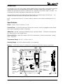
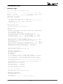
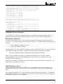
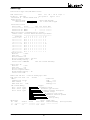
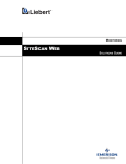
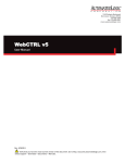
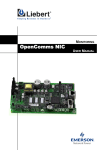
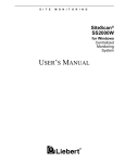
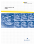
S I T E M O N I T O R I N G SiteGate-232 USER’S MANUAL SiteGate-232 Technical Instructions Contents Introduction .................................................................................................. 3 Specifications .............................................................................................. 3 Network Communications ........................................................................... 4 System Architecture .................................................................................... 5 Mounting ...................................................................................................... 5 Power Wiring ................................................................................................ 6 Addressing, Baud Rates, and Console Settings ....................................... 7 Communication Wiring ............................................................................... 8 CMnet Wiring ......................................................................................... 8 The "SETGCM" Command .......................................................................... 8 Transferring Memory ................................................................................... 9 Cables ........................................................................................................... 9 Cable Diagrams for Console Port #1 ................................................. 10 Cable Diagrams for Console Port #2 ................................................. 10 Checkout & Troubleshooting .................................................................... 11 Troubleshooting Procedure ............................................................... 11 Common Problems ............................................................................. 11 Manually Formatting the Module ....................................................... 12 LEDs ..................................................................................................... 12 LED Identification ................................................................................ 12 LED Power-up Sequence .................................................................... 13 Fuses .................................................................................................... 14 LGM Module Driver .................................................................................... 14 Parameter Page ................................................................................... 14 LGM Module Driver Parameters ......................................................... 16 Status Page .......................................................................................... 18 LGM Module Driver Status .................................................................. 19 Rev. (08-JULY-98) 2 © 1996-98 Liebert Corporation Introduction The SiteGate-232 is part of the Liebert SiteScan gateway family and provides communications between a workstation and a control module network (CMnet) consisting of fewer than 50 modules. The SiteGate-232 provides two EIA-232 Console Ports for connecting a workstation and/or a modem. The console ports are switch selectable for baud rates up to 38.4k bps. Communication between the SiteGate-232 and the CMnet is provided through a EIA-485 port. SiteGate-232 does not have a Direct Network (DN) connection. The NOTE: You must use FB Link v2.7 or later in order to transfer to any module containing Exec 6.0 or later. Specifications Power: 24 VAC ±10%, 50-60 Hz, 7.2 VA. Console Ports: (2) EIA-232 serial ports (D-sub 9-pin connector, and 5-pin pluggable screw terminal block) switch selectable for 9600 or 38.4k bps. CMnet Port: EIA-485, twisted pair, 9600/38.4k bps, optically isolated. (156k bps to be supported by a future version of the module driver). Status Indication: Visual (LED) status of EIA-232 communication, CMnet communication, running, errors, and power. Temperature Range: 0-130 °F (-17.8 to 54.4 °C). Humidity Range: 10%-95% relative humidity, non condensing. Memory: 1 MB FLASH memory for module driver storage and 1024 kB of battery backed RAM. 1" EIA-232 Console Port 1 Power Switch Console Port n/c 1 dcd 2 rx 6 +10v 7 n/c 8 n/c 9 3 tx 4 dtr 5 gnd Off On Power Indicator Power Supply Power Switch Gro und 24 V AC Us e sin gle Cl ass 2 sou rc e o nl y Cl as s 2 50 -6 0 Hz 2 4 VAC 0. 4 Am p Us e c opp er co nd uc to r on ly SiteGate-232 EIA-232 Console Port 2 Auxiliary Device Port CMnet Baud Rate Jumper Access Port Tx Rx 7 1/8" Cons ole 2 Manual Format Button Optional S hield Auxiliary Device Port Forma t b utton Baud 156K Baud 9600/38.4K Run Error CM net Rec ei v e Cm net Trans m it Cons ole 2 reci eve Cons ol e 2 transm it Cons ole 1 reci eve Cons ol e 1 transm it CM net baud 9600 Cons ol e 1 baud 9600 Cons ol e 2 baud 9600 38.4K 38.4K 38.4K Addressing Dip Switch Access port Opti ona l S hie ld CMne t co nn ec tion Net Net + CMnet Connection 1 5/8" 6 1/4" LEDs Figure 1: SiteGate-232 Module Dimensions and Layout Rev. (08-JULY-98) 3 © 1996-98 Liebert Corporation Battery: Seven-year lithium battery provides a minimum of 10,000 hours of data retention during power outages. Fault Detection: Hardware watchdog timer. Software Requirements: One LGM module driver as FB #15. Workstation software must be SiteScan for Windows v2.5b or later, Alert 1.1a or later, and FB Link v2.7 or later. Protection: ESD protection on Console Port 1. Voltage, current, and ESD protection on Incoming Power, CMnet, and Console Port 2. Hardware Accessories: Keypad display. Listed By: PAZX (UL916), cUL C22.2 No. 205-M1983. Network Communications The CMnet is a peer-to-peer network which allows the various control modules to communicate with each other. An IBM-compatible computer can communicate on the CMnet through the SiteGate-232 when direct-connected (DC) or modem-connected (MC), or it can communicate on the CMnet through any other module with a Direct-Network (DN) connection. The SiteGate-232 does not have a DirectNetwork (DN) connection. The CMnet communicates using the EIA-485 standard. A "token passing" scheme is used so that each module has the token in turn. When a module has the token, it broadcasts whatever information is appropriate from its FBs, while all other modules on the CMnet listen. Any module may receive information from any other module, but it may broadcast only when it has the token. When a module is finished with the token, it passes it to the next module (or back to the gateway, if using grabless token passing) by broadcasting a token-pass message using the next module's address. The receiving module must acknowledge this message to complete the pass. The SiteGate-232 listens for an address which is equal to the total number of modules on the CMnet plus one (also referred to as the Maxnet value). When the last module on the CMnet attempts to pass the token by broadcasting the Maxnet value, the SiteGate-232 acknowledges the token and starts the cycle over. Signal integrity on the CMnet is affected by the wire gauge and the total amount of wire in the Workstation EIA -232 (Up to 38.4 kbps) Workstation Modem EIA -232 (Up to 38.4 kbps Dial up telephone line SiteGate-232 Modem UCM 10-8 DCU RCM 10U IGM DC 1 RCMEX P OCM-8 CMnet EIA -485 38.4 kbps 50 nodes max imum Figure 2: System Architecture (Small System) Rev. (08-JULY-98) 4 © 1996-98 Liebert Corporation segment. A segment is defined as the network of modules between main nodes. Main nodes can be represented by a gateway module, or a repeater (part no. REPOPT). A repeater can be used to end one segment and begin another, all on the same CMnet. It is recommended that only a dedicated, 22AWG to 18AWG twisted pair copper wire be used for CMnet (EIA-485) wiring. Wire sizes smaller than 22 gauge or wires that are not twisted may cause intermittent communication problems. NOTE: For further explanation of communications wiring, see the Technical Handbook. System Architecture The Liebert Architecture is designed to support both large and small systems. Small systems (those using less than 50 control modules) require only a single SiteGate-232 which serves the entire Control Module Network, or CMnet (see Figure 2). The SiteGate-232 communicates with the workstation via a EIA-232 serial communication port. A second EIA-232 port can be used for communication with another operator workstation or a portable field computer via modem or direct EIA-232 connection. The SiteGate-232 communicates with the CMnet through a EIA-485 port. This CMnet is a peer-to-peer local area network which uses a "token-passing" protocol to allow all control modules to communicate with one another with equal authority. Each control module is capable of stand-alone DDC (Direct Digital Control), thus increasing system reliability and performance. Mounting Mount the SiteGate-232 in an enclosure using the four holes provided on the module's cover plate (see Figure 3). Recommended screw size is 8. Make sure that nothing comes in contact with the back of the printed circuit board, and leave approximately 2 inches on each side for wiring. The SiteGate-232 is designed to be mounted inside the building envelope. All warranties are void if mounted outside. te-2 Ga Site 32 Figure 3: Mounting the SiteGate-232 Rev. (08-JULY-98) 5 © 1996-98 Liebert Corporation Power Wiring CAUTION: The SiteGate-232 modules are Class 2 devices (less than 30 VAC). Take appropriate isolation measures when mounting a SiteGate-232 module in a control panel where Class 1 devices or wiring are present. NOTE: Whenever possible, terminate and verify power and communication to all modules before terminating any inputs and outputs. 1. Terminate AC power at the wiring source (usually a circuit breaker or other AC source). 2. Apply power to the transformer. 3. Turn the SiteGate-232's power switch OFF (see Figure 1 for location) to prevent the module from being powered up until proper voltage is verified. 4. If you are using an internally grounded transformer, terminate the Earth Ground wire to the Gnd screw terminal as indicated in Figure 4. CAUTION: Be sure to follow proper polarity on power connections. Note INCORRECT power wiring in Figure 5. If the transformer is not internally grounded, terminate the two power wires as indicated in Figure 6. 5. Verify that 24 VAC is present at the power input terminals and turn the SiteGate-232's power switch on. 6. Once the power wiring procedure has been completed, the "Run" LED should turn on and begin blinking. If this does not occur, turn the power switch off and check for wiring errors. Figure 4: SiteGate-232 module powered by transformer with Earth Ground Rev. (08-JULY-98) Figure 5: INCORRECT wiring of the Figure 6: SiteGate-232 module SiteGate-232 module powered by powered by transformer with Floating transformer with Earth Ground Ground 6 © 1996-98 Liebert Corporation Addressing, Baud Rates, and Console Settings The SiteGate-232 module's address is factory-set as control module #1 and cannot be changed. NOTE: The CMnet Baud Rate jumper (see Figure 1 for location) is only used to configure the CMnet for 156k bps. If the CMnet Baud Rate jumper is set to 156k, the CMnet Baud DIP switch is ignored. The CMnet communication speed and baud rates for the SiteGate-232's console ports are configured using an 8-position DIP switch. The following is a list of each switch position and its function. DIP Switch Number Function 1 This switch selects the CMnet communication baud rate. When this switch is in the left position, the SiteGate-232's CMnet baud rate is set at 9600 bps. When the switch is in the right position, the CMnet baud rate is set at 38.4k bps. NOTE: All modules on the CMnet must use the same baud rate. 2 This switch selects Console 1's communication baud rate. When this switch is in the left position, the Console 1 baud rate is set at 9600 bps. When the switch is in the right position, the Console 1 baud rate is set at 38.4k bps. 3 This switch selects Console 2's communication baud rate. When this switch is in the left position, the Console 2 baud rate is set at 9600 bps. When the switch is in the right position, the Console 2 baud rate is set at 38.4k bps. 4-8 Not used. Example: As shown in Figure 7, switch 1 is in the 38.4k position, switch 2 is in the 9600 position, and switch 3 is in the 38.4k position. As a result, the SiteGate-232 is configured as follows: • The CMnet baud rate is set at 38.4k bps. • The Console 1 baud rate is set at 9600 bps. • The Console 2 baud rate is set at 38.4k bps. Figure 7: Setting the SiteGate-232's Dip Switch Rev. (08-JULY-98) 7 © 1996-98 Liebert Corporation Procedure 1. Turn the SiteGate-232's power switch OFF. 2. Set the module's baud rates and console port settings using the 8-position dip switch (see Figure 1 for switch location). 3. Turn the SiteGate-232's power switch ON. Communication Wiring CMnet Wiring NOTE: Only one SiteGate-232 may exist on a CMnet. NOTE: The EIA-232 connection can be 50 ft. (15.24 m) maximum. 1. Turn the SiteGate-232's power switch OFF. 2. Check the network communication wiring for shorts and grounds. 3. Terminate the network (CMnet) communication wires (#18 twisted pair) to the module's screw terminals indicated in Figure 8. NOTE: Be sure to follow the same wiring polarity as established throughout the rest of the network. 4. Turn the SiteGate-232's power switch ON. 5. Verify proper network communication using Netscan software. 24VAC Power Switch Console Port n/c 6 +10v 7 n/c 8 n/c 1 dcd 2 rx 3 tx 4 dtr 5 gnd Off Power Indicator On Power Supply Gro und Line Voltage 24 VAC Us e sin gle Cl ass 2 sou rc e o nl y Cl as s 2 50 -6 0 Hz 2 4 VAC 0.4 Amp 9 Us e c opp er co nd uc to r on ly SiteGate-232 Tx Rx Cons ole 2 Optional Shield Auxiliary Device Port Forma t b utton Baud 156K Baud 9600/38.4K Run Error CM net Rec eiv e Cm net Trans m it Cons ole 2 recieve Cons ole 2 transm it Cons ole 1 recieve Cons ole 1 transm it CM net baud 9600 Cons ole 1 baud 9600 Cons ole 2 baud 9600 38.4K 38.4K 38.4K Access port Opti ona l Shie ld CMne t co nn ec tion Net Net + #18 Twisted pair to CMnet Figure 8: Power and communications wiring Rev. (08-JULY-98) 8 © 1996-98 Liebert Corporation The "SETGCM" Command The "SETGCM" command initializes the SiteGate-232 with system parameters including Maxnet, the workstation telephone number from the SiteScan connections page (set only for the port(s) which are connected when this command is issued), and the system's line number and 3-letter system name. The "SETGCM" command is required whenever one of the following events occur: • The SiteGate-232 module is replaced or reformatted. • A new module is added to the network. • The workstation phone number is changed on the SiteScan connections page. • The three letter system name is changed. To issue this command, connect to the system through SiteScan, press [ESC], type SETGCM, and press [ENTER]. NOTE: If the "Use This Number?" parameter on the LGM module driver parameter page is set to "YES", the SiteGate-232 disregards the phone number transferred by the SETGCM command. Instead, it uses the phone number entered on the LGM module driver parameter page. A different phone number may be entered for each EIA-232 port. Transferring Memory NOTE: You must use FB Link v2.7 or later in order to transfer to any module containing Exec 6.0 or later. If you have any problems during this procedure, contact Technical Support at 1-800-LIEBERT (1-800-543-2378). 1. Log into SiteScan, using a workstation or portable computer that is direct connected, modem connected, or connected directly on the Liebert network. 2. Go to the SiteGate-232's Modstat page as follows: • Press the [ESC] key • Type: MO ,, 1, 15 If the module is on-line and communicating, this command will bring up a Modstat page. 3. Look at the Modstat page and verify that the module's type is SiteGate-232 and address is CM1. 4. Download memory for “This Module.” 5. When the memory transfer is finished, go to the module's Modstat page (see Step 2). Check the screen display's FB List to verify that the module driver you intended to transfer is in the module. Rev. (08-JULY-98) 9 © 1996-98 Liebert Corporation Cables Several cables, which vary depending upon the communication requirements, are available. The following is a description and wiring configuration of each cable (the arrows indicate direction of data flow). Cable Diagrams for Console Port #1 ATAD The ATAD cable connects a 9-pin EIA-232 port to a 25-pin Hayes or compatible modem. The cable pin-out is as follows: 9-pin EIA-232 (DE-9S) Modem (DB-25P) DCD 1 8 DCD RX 2 3 RX TX 3 2 TX DTR 4 20 DTR GND 5 7 GND DSR 6 6 DSR RTS 7 4 RTS CTS 8 5 CTS RI 9 22 RI DC95 The DC95 cable direct-connects the 9-pin SiteGate-232 console port to a 25-pin workstation EIA-232 port (DE9 to DB25). The cable pin-out is as follows: SiteGate-232 (DE-9S) CD RX TX DTR GND Workstation (DB-25S) Brow n Red Green White Black 1 2 3 4 5 4 3 2 1 5 DTR TX RX CD GND DC99 The DC99 cable direct-connects the 9-pin SiteGate-232 console port to a 9-pin workstation EIA-232 port (DE9 to DE9). The cable pin-out is as follows: SiteGate-232 (DE-9S) Workstation (DE-9S) CD RX TX DTR GND Rev. (08-JULY-98) 1 2 3 4 5 Brow n Red Green White Black 4 3 2 1 5 DTR TX RX CD GND 10 © 1996-98 Liebert Corporation Cable Diagrams for Console Port #2 Direct-connect to 25 pin workstation Port SiteGate-232 Console Port #2 Terminal Number Workstation Port (DB-25S) Pin Number TX 1 3 RX RX 2 2 TX 3 No connection required 4 No connection required GND 5 7 GND Direct-connect to 9 pin workstation Port SiteGate-232 Console Port #2 Terminal Number Workstation Port (DB-9S) Pin Number TX 1 2 RX RX 2 3 TX 3 No connection required 4 No connection required GND 5 GND 5 Modem connection SiteGate-232 Console Port #2 Terminal Number Modem (DB-25P) Pin Number TX 1 2 TX RX 2 DTR 3 3 RX 20 DTR CD GND 4 5 8 CD 5 GND Checkout & Troubleshooting Checkout on the SiteGate-232 is performed by using both the (DC99 or DC95) Direct Connect cables. Troubleshooting Procedure A workstation may contain a 9 pin or a 25-pin COM port or both. COM port. Use a DC99 cable with a 9-pin COM port. Use a DC95 cable with a 25-pin 1. Direct connect to console 1. 2. Go to the Modstat page for the SiteGate-232. 3. Transfer the module driver and verify on the Modstat page that the transfer was successful. 4. Make sure that the transmit and receive lights for that port are operating properly. 5. Verify that the SiteGate-232 has communication with other modules on the CMnet. Rev. (08-JULY-98) 11 © 1996-98 Liebert Corporation Common Problems Modem connected to the SiteGate-232 will not answer. Make sure the TR light on the modem is ON; if it is OFF check the modem cables. Verify connection and baud rate with the SiteGate-232. Modem connect to SiteGate-232 will not dial out. Make sure the modem installed on this port is set to "yes" in the LGM Parameter page under Console Port # and a valid phone number has been set using SETGCM or by manually entering a phone number. WRU Failure. WRU failures occur when there is a problem between the SiteGate-232 and the modem. Verify correct speed on the modem and SiteGate-232. Verify the correct cable is used and be sure it follows the ATAD cable pinout. Manually Formatting the Module Manually formatting the module does not require communication with the module. Use this procedure as a last resort when there is no communication with the module. Although transferring memory overwrites all existing memory, it requires communication in order to initiate the transfer. WARNING: Formatting the module erases all transferred memory. The Transferring Memory procedure must be followed after formatting. 1. Turn the SiteGate-232's power switch OFF. 2. Press and hold the manual format button (see Figure 1). 3. Turn the SiteGate-232 module's power ON. 4. Wait a few seconds. 5. Release the manual format button. The module is now formatted. Rev. (08-JULY-98) 12 © 1996-98 Liebert Corporation LEDs LED Identification The SiteGate-232's LEDs are as follows (see Figure 11): Power - indicates when power is on. Run - blinks when the processor is running. Error - lights when an error is detected. CMnet Receive - lights when SiteGate-232 receives data from the CMnet. CMnet Transmit - lights when SiteGate-232 transmits data over the CMnet. Console 2 Receive (RX) - lights when Console 2 port receives data. Console 2 Transmit (TX) - lights when Console 2 port transmits data. Console 1 Receive (RX) - lights when Console 1 port receives data. Console 1 Transmit (TX) - lights when Console 1 port transmits data. RUN LED ERROR LED CONDITION 2 flashes per sec. Off All normal 2 flashes per sec. 2 flashes per sec. 5 minute auto-restart delay after system error. 2 flashes per sec. On Exec halted after frequent system errors. 5 flashes per sec. On Exec startup aborted, Boot is running. 5 flashes per sec. Off Firmware download is in progress by Boot. 7 flashes per sec 7 flashes per sec. Brownout recovery delay (10 seconds) 14 flashes per sec. 14 flashes per sec. Brownout in progress (supply voltage low) Power Switch Console Por t Run Error CMnet Receive Cmnet Transmit Console 2 recieve Console 2 transmit Console 1 recieve Console 1 transmit n/c +10v 7 n/c 8 n/c 1 dcd 2 rx 3 tx 4 dtr 5 gnd 6 Off Power Indicator On Power Supply Gro und POWER 24 V AC Us e sin gle Cl ass 2 sou rc e o nl y Cl as s 2 50 -6 0 Hz 2 4 VAC 0.4 Am p 9 Us e c opp er co nd uc to r on ly SiteGate-232 Tx Rx Cons ole 2 Optional Shield Auxiliary Device Port For ma t b utton Baud 156K Baud 9600/38.4K Run Error CM net Rec eive Cm net Trans mit Cons ole 2 recieve Cons ole 2 transm it Cons ole 1 recieve Cons ole 1 transm it CM net baud 9600 Cons ole 1 baud 9600 Cons ole 2 baud 9600 38.4K 38.4K 38.4K Access port Opti ona l S hie ld CMne t co nn ec tion Net Net + Figure 11: SiteGate-232 LED Identification Rev. (08-JULY-98) 13 © 1996-98 Liebert Corporation LED Power-up Sequence During power-up, the module goes through an initialization and self test sequence. Proper module power-up can be verified by observing the LEDs as follows: 1. The Run and Error LEDs turn on and begin blinking. 2. The Error LED will then turn off. 3. The Run LED will continue blinking. If the module is not responding and the LEDs do not appear to be going through the appropriate initialization, call Technical Support for assistance. NOTE: The Error LED flashes three times in sync with the Run LED when the module is formatted. The Run LED should never stop flashing. If it stops flashing for 1.5 seconds, the watchdog timer will reset the CPU. Fuses The SiteGate-232 is protected by internal solid state fuses on the incoming power and CMnet. These fuses are not replaceable and will reset themselves in the event of a transitory condition. Rev. (08-JULY-98) 14 © 1996-98 Liebert Corporation LGM Module Driver Parameter Page Function Block Type: LGM (LGM Module Driver) Name SiteGate-232 ID ID14 Tele NB Power Up Delay 0 (sec) Update Time 0:00 (mm:ss) Line 1 LG 2 CM 1 FB 15 Flags — All Options Y Type 67 Ver 1 Demand Controller Address 0 ,0 BACnet Device Parameters: Use default device object name? Y Device Name = Use default device object ID? Y Device ID = (device object, 0) APDU Timeout ............. 3000 (milliseconds) Number of APDU Retries ... 0 GFB performance tuning: ======================= Time slice per GFB = 5000 milliseconds. CMnet Parameters: General: Generate a “Dead Module” alarm after 10 minutes of no communications with a control module. Zero compression enabled? YES Output character pacing? (reduces throughput by 50%) NO Delay before sending all replies (20 msec minimum) = 20 msec. Interpacket delay .............. (20 msec minimum) = 20 msec. Alternate interpacket delay .... (40 msec minimum) = 40 msec. CMnet Tuning Parameters: (Tech Support Only) Time to wait for ‘?’ before attempting intrusive grab = 500 Maximum number of intrusive grab attempts per request = 3 Grab Silence Time = 600 Time to hold the token when the token wraps around = 1 Time to wait for each module to acknowledge the token = 500 Maximum online time per successful grab = 0:50 (mm:ss) Maximum monitor time per monitor request = 5:00 (mm:ss) msec. msec. seconds msec. Console Port #1 Parameters: Modem installed on this console port = NO Modem control parameters: Modem Reset ATV0E0Q0S0=1S7=60 Dial Prefix ATDT Phone Number Use This Number? NO (NO = use number from SETGCM ) If not connected, and with no alarms pending delivery, reset modem every 5:00 (mm:ss). Note: the minimum value for this is 5:00. If connected, but no activity has been detected for 20:00 (mm:ss), hang up and reset modem. After dialing, wait 2:00 (mm:ss) for connection before hanging up. After unsuccessful alarm delivery, wait 5:00 (mm:ss) before trying again. Escape (+++) guard time 1000 msec. Post hangup delay 1000 msec. Reset time (DTR low) 1000 msec. Post DTR high delay 500 msec. Post reset string delay 1000 msec. Console Port #2 Parameters: Modem installed on this console port = NO Modem control parameters: Modem Reset ATV0E0Q0S0=1S7=60 Dial Prefix ATDT Phone Number Use This Number? NO (NO = use number from Rev. (08-JULY-98) SETGCM ) 15 © 1996-98 Liebert Corporation If not connected, and with no alarms pending delivery, reset modem every 5:00 (mm:ss). Note: the minimum value for this is 5:00. If connected, but no activity has been detected for 20:00 (mm:ss), hang up and reset modem. After dialing, wait 2:00 (mm:ss) for connection before hanging up. After unsuccessful alarm delivery, wait 5:00 (mm:ss) before trying again. Escape (+++) guard time 1000 msec. Post hangup delay 1000 msec. Reset time (DTR low) 1000 msec. Post DTR high delay 500 msec. Post reset string delay 1000 msec. Enable daylight saving time changeover from this module NO . Do not enable this if you have an XFG, XFR, XFT, or XFZ on this CMnet. Module generated Alert alarms: Module Halted: Alarm ID: A250 Enable: YES Critical: One or more GFBs stopped: Alarm ID: A253 Enable: YES Critical: Manual I/O Locked (for each GFB): Alarm ID: A1 Enable: YES Critical: GFB parameter or other error (for each GFB): Alarm ID: M4 Enable: YES Critical: YES Send RTN: YES YES Send RTN: YES YES Send RTN: YES YES Send RTN: YES LGM Module Driver Parameters The SiteGate-232 is properly configured by altering the module driver parameter page values. The parameters are used for defining dialing information, modem control, and CMnet characteristics. BACnet Device Parameters Use default device object name? This is a character string that represents the unique internetworkwide object. The minimum length of the string is one character. The default string of this parameter is LGxCMy. x y parent LANgate LG address in decimal Portal's CM address in decimal Use default object ID? This is a numeric code that is used to identify the object. Choose NO to enter a custom object ID (range: 1-4194303). Otherwise a default string of 240zzz will be assigned. zzz parent LANgate LG address in decimal plus CMnet address in decimal APDU Timeout Indicates the amount of time between retransmissions of an APDU requiring acknowledgement for which no acknowledgement has been received. The default value of this parameter is 3000 milliseconds. Number of APDU Retries Indicates the maximum number of times that an APDU is transmitted. The default value of this property is zero (0). CMnet Parameters General Generate dead module alarm after 10 minutes of no communications with a control module. If a module has not reported its color within this time, the SiteGate-232 will generate a "dead module" alarm. Zero compression enabled? YES: Zero compression makes the CMnet more efficient. This parameter should always be set to YES. It should only be set to NO if there is a need to examine uncompressed CMnet traffic to diagnose a CMnet problem. Rev. (08-JULY-98) 16 © 1996-98 Liebert Corporation Output character pacing? If set to YES, this parameter reduces CMnet transmission speed by 50%. This may be necessary when operating at 38.4k baud with older modules on the same CMnet. Delay before sending all replies (20 msec minimum) = 20 msec: The time in milliseconds to wait before replying to CMnet commands. This is necessary to allow the sender time to shut off its transmitter and prepare to receive the reply. If the reply comes too quickly, it may be missed. Interpacket delay....... (20 msec minimum) = 20 msec: The delay time in milliseconds between successive CMnet messages sent by this module. This allows all receiving modules time to take action on each message. Alternate interpacket delay... (40 msec minimum) = 40 msec: This parameter is the same as the Normal interpacket delay parameter, except this delay is used between color update messages which require more time for the receiving module to process. CMnet Tuning Parameters Time to wait before attempting intrusive grab: This is the time allowed after a grab request on a console port for a non-intrusive grab to be successful before resorting to an intrusive grab. A nonintrusive grab is when the SiteGate-232 takes control of the CMnet without sending a stream of “! ! ! ! !...” characters. This can only be successful if the modules on the CMnet employ the “grabless” token passing scheme. A non-intrusive grab is preferred over an intrusive grab because it is quicker and non-disruptive. Maximum number of intrusive grab attempts per request: If the non-intrusive grab is unsuccessful, the SiteGate-232 will attempt this many intrusive grabs before giving up entirely and returning a negative acknowledgment on the console port that requested the grab. Grab Silence Time: The CMnet must be silent for at least this long after an intrusive grab attempt to consider the grab successful. Time to hold the token when the token wraps around: When the CMnet token is passed from the module with the highest CM address to the SiteGate-232 (CM address #1), the SiteGate-232 will hold the token for this amount of time before passing it to module #2. This is useful for reducing the rate of time broadcasts on CMnets with low module counts, because the SiteGate-232 broadcasts the time every time the CMnet token is passed to it. Time to wait for each module to acknowledge the token: When the SiteGate-232 passes the CMnet token to a module, it will wait this long for the module to acknowledge that the token was received before skipping it and passing the token to the next module. Maximum online time per successful grab: The amount of time any console port is allowed to be online on the CMnet after each successful grab. If the online time expires, the console port will be disconnected from the CMnet and the SiteGate-232 will restart the CMnet token. Maximum monitor time per monitor request: The amount of time any console port is allowed to monitor the CMnet after each monitor request. If the monitor time expires, the console will be disconnected from the CMnet and an additional monitor request must be issued to continue monitoring. Console Port Parameters Modem installed on this console port = No: This enables the use of a modem on the console port. Rev. (08-JULY-98) 17 © 1996-98 Liebert Corporation Modem Control Parameters Modem Reset: This is a user definable parameter that sends a reset string to the modem. Dial Prefix: This parameter sets the dial prefix used for dialing out alarms. Phone Number: This parameter sets the number to be dialed out for alarms. Use This Number? NO: If "YES", the phone number above will be used for dialing out to deliver alarms. If "NO", the phone number on the workstation will be used for dialing out to deliver alarms. The phone number that is currently selected will appear on the status page. If not connected, and with no alarms pending delivery, reset modem every 5:00 (mm:ss): This parameter sets how often the SiteGate-232 will send the modem reset string. If connected, but no activity has been detected for 20:00 (mm:ss), hang up and reset modem: This parameter sets the amount of time before the modem hangs up when there has been no data flow between the SiteGate-232 and the Workstation. It also sends the modem reset string after it hangs up. After dialing, wait 2:00 (mm:ss) for connection before hanging up: This parameter sets how long the SiteGate-232 will wait for a carrier detect before it hangs up the modem. After unsuccessful alarm delivery: This parameter sets how long the SiteGate-232 will wait before dialing back alarms after an unsuccessful alarms delivery. Escape (+++) guard time: This parameter determines the time delay before and after the escape sequence to allow the modem to receive and acknowledge it. Post hangup delay: This parameter determines how long the SiteGate-232 waits after sending the modem hangup command. Reset time (DTR Low): This parameter determines how long the SiteGate-232 holds the DTR line low for disconnecting the modem. Post DTR high delay: This parameter determines how long the SiteGate-232 waits after returning DTR to its active (high) state after a modem reset. Post reset string delay: This parameter determines how long the SiteGate-232 waits after sending the reset string to the modem. Enable daylight saving time changeover from SiteGate-232 When set to "YES", the SiteGate-232 will make daylight saving time adjustments to its own clock and the clock of all modules on its CMnet. Do not enable this if you have an XFG, XFR, XFT, or XFZ Function Block on this CMnet. Rev. (08-JULY-98) 18 © 1996-98 Liebert Corporation Status Page Function Block Type: LGM (LGM Module Driver) Name SiteGate-232 Line 1 LG 1 CM 1 FB 15 Flags --ID CM01_15 Tele DC26 All Options Y Type 83 Ver 1 Status-Code 10 Current Demand Level 0 Module Status: Auto-Restart Delay General GFB shutdown Module Halted One or more GFBs stopped ---Alarm buffer status: Owner's Name Status Size Last Access Time ================ =============== ===== ================= Console Port #1 EMPTY 0 --/--/-- --:--:-Console Port #2 EMPTY 0 --/--/-- --:--:-ARC156 Statistics: (refreshed every 40 seconds) Modules Online Relative ARC156 Utilization per Module ============== ======================================= 1234567890 1 2 3 4 5 6 7 8 9 10 00:X-----X--00:1 0 0 0 0 0 1 0 0 0 10:---------10:0 0 0 0 0 0 0 0 0 0 20:---------20:0 0 0 0 0 0 0 0 0 0 30:---------30:0 0 0 0 0 0 0 0 0 0 40:---------X 40:0 0 0 0 0 0 0 0 0 90 50:---------50:0 0 0 0 0 0 0 0 0 0 60:---------60:0 0 0 0 0 0 0 0 0 0 70:---------70:0 0 0 0 0 0 0 0 0 0 80:---------80:0 0 0 0 0 0 0 0 0 0 90:---------90:0 0 0 0 0 0 0 0 0 0 Console Port #1: Baud rate = 38400 Input echo = NO Dialout enabled = NO Dialout telephone number = 555-1212 Alarms Pending Delivery = NO Console state: CONNECTED with 1200 seconds remaining. Console Port #2: Baud rate = 9600 Input echo = NO Dialout enabled = NO Dialout telephone number = Alarms Pending Delivery = NO Console state: IDLE Module time and date = 16:49:20 Tuesday Apr-7-1998 Time since last reset = 48 seconds. CMnet: Outside Air: Communication lost NO Temp 0.00 CMnet address 1 Humidity 0.00 CMnet baud rate 156K Enthalpy 0.00 GFB & Trend Memory: Free = 720376 bytes Used = 65954 bytes Total= 786330 bytes GFB Roster: No. Name === ======== 15 LGM Rev. (08-JULY-98) Version ======== 1.0 Stopped Parameters corrupt Parameters type incorrect Parameter transfer interrupted Schedule corrupt FB execution code corrupt Microblock execution problem I/O Locked Power up delay Status ========= --------- Rate ==== N/A Bytes Used ====== 65952 19 Trend Count: Enabled Trending ======= ======== (Rate=cycles/min) © 1996-98 Liebert Corporation LGM Module Driver Status This is the overall module status. Function Block Type: This the Module Driver's three-character filename. Name: This is the name referring to the space or equipment used. Line: The telephone line number used by the Function Block. LG: Gateway module number used by the Function Block. CM: Control Module number used by the Function Block. FB: Function Block number used by the Function Block. Flags: This identifies three flags which indicate the FB is "marked" because of certain conditions. P M ID: Indicates that the FB is not marked. Indicates that there has been a change to the FBs parameter page which has not been transferred to the module. Indicates that memory transfer has failed for this Function Block. This is an identification of up to eight characters (the first of which must be an alphabetic character) assigned to each FB. Every FB in the system has a unique ID. Tele: This indicates the telephone number for the FB's gateway module. All Options: This is the only changeable parameter in the Header portion of the FB and toggles between Y and N. Y All parameters become visible even if they have not been defined. N Only defined parameters are shown. Type: This parameter indicates how often the Function Block has been made in Eikon. If this parameter does not match the corresponding parameter in the module, all parameters are displayed in yellow and cannot be changed. Also, parameters cannot be uploaded or transferred. Function Blocks having mismatched type do not have their parameter written to configuration text when the configuration text is updated. To correct this problem, download memory to the module. This parameter is checked when the FB is first displayed and after a successful memory transfer. This parameter is not related to the Version microblock in Eikon. Ver: This is the parameter that indicates how many times the FB's parameters have been changed. If the FB file in the computer does not match the FB which is transferred in the module, the Ver parameter and the parameters which do not match are displayed in purple. To correct this problem, either upload or transfer the parameters. This parameter is not related to the Version microblock in Eikon. Module Status This is the overall module status and indicates if any of the following conditions exist: Auto-Restart Delay: The system has just restarted after a System Error and the module will not start GFB execution until the auto-restart delay (5 minutes) has timed out. This prevents equipment from being short cycled in the event of repeated System Errors. Rev. (08-JULY-98) 20 © 1996-98 Liebert Corporation Module Halted: All GFB related tasks have stopped. This can only happen if there have been 3 or more frequent System Errors. System Errors are errors that are severe enough to cause the module to reset. The module can still partially communicate on the CMnet when in this Halted state, but color updates and LAN I/O requests will cease causing the gateway to declare this module “dead”. (System Errors are logged and time stamped on the Modstat screen). General GFB Shutdown: All GFBs are stopped because of one of the following reasons: a) The module driver’s parameters became corrupt in memory. b) Any GFBs microblock sequence or parameters became corrupt while the GFB was running. c) A module driver parameter transfer was started and never finished (i.e. it was incomplete). One or more GFBs Stopped: At least one GFB is stopped for one of the following reasons: a) Parameters were being transferred to the GFB and the transfer did not complete. b) There was a problem running one of the microblocks in the GFB. c) The GFB parameters transferred do not match the microblock sequence (RP) type. d) The GFB parameters became corrupt in memory. Console 1 and 2 Baud rate = 9600: This shows the baud rate for the console port. Input echo = NO: This shows if the echo is enabled on the console port. Dialout enabled = NO: This shows if modem dialout is enabled on the console port. Modem dialout will automatically be enabled if a valid phone number exists and the "Modem installed on this port" parameter is set to "YES". Dialout telephone number = NC: This shows the actual telephone number that the SiteGate-232 will use to dialout alarms. Alarms Pending Delivery = NO: This shows if there are any critical alarms in the console port buffer ready to be delivered. Console state: This shows the current state of the console port. The possible states are: IDLE = The port is not in use. CONNECTED = The port is connected to the workstation. ON CMNET = The workstation is online on the CMnet. DIALING = The modem is dialing out. DIALED = Dialing is complete, but the workstation has not yet responded. STARTING REDIAL = Dial out was unsuccessful. WAITING REDIAL = Waiting to dial out RESETTING MODEM = The modem is hanging up and resetting. Console 1 alarm buffer status: The status of the alarm buffer is shown for console port 1. The"buffer state" will show one of the following: EMPTY = No alarms waiting to be delivered. NON-CRITICAL = Non-critical alarms are waiting to be delivered. CRITICAL = Critical alarms are waiting to be delivered. CRITICAL/FULL = Same as above, and the buffer is also full. Rev. (08-JULY-98) 21 © 1996-98 Liebert Corporation Module time and date: Shows the current module date and time. Time since last reset: The amount of time that has elapsed since the last module reset. CMnet Communication lost: If "YES", this module has detected that it is alone on this CMnet. CMnet address: The module’s current CMnet node address. This should be set to 1 for the SiteGate232. CMnet baud rate 9600: The module’s current CMnet baud rate. Module Driver Memory Free: Unused module driver memory. Used: Memory used by the module driver. Total: Maximum memory capacity of this module . Module Driver No.: This is the GFB number as configured in EDB. Name: This is the GFB name as configured in Eikon. Version: This is the version of the GFB. This number is incremented each time the FB is compiled in Eikon. Status: There are nine status states which are defined on the Status Page. An X indicates that the state exists, a dash (-) indicates that it does not exist. Rate: This number indicates how many times the GFB will execute per minute (Cycles/Minute). Bytes Used: Indicates how much of the module's memory is used by the GFB. Rev. (08-JULY-98) 22 © 1996-98 Liebert Corporation SiteGate-232 - User's Manual A World Leader in Computer Support Systems Environmental Control • Power Protection • Site Monitoring/Control Service • Parts • Training Liebert Corporation designs, manufactures, and markets complete systems for improvement of computer uptime and performance. The result is improved business operations, increased productivity and higher return on the computer investment. Liebert Systems provide dependable environmental control, electrical power protection, centralized monitoring and control, and remote monitoring. Liebert supports its products with a combination of preventive maintenance, emergency repairs, depot repairs, parts, technical assistance, and training. This approach represents a single-source integrated computer support network. Based on over three decades of experience and more than 500,000 installations worldwide, Liebert is committed to offering the highest quality products and services for applications requiring computer support. Ke e p i n g B u sin e ss in Bu sin e ss Liebert Corporation Liebert Europe 1050 Dearborn Drive P.O. Box 29186 Columbus OH 43229 Telephone: 614.888.0246 Facsimile: 614.841.6022 Elgin Drive Swindon Wiltshire SN2 6DX United Kingdom Telephone: 441.793.553.355 Facsimile: 441.793.553.400 While every precaution has been taken to ensure accuracy and completeness in this manual, Liebert Corporation assumes no responsibility, and disclaims all liability for damages resulting from use of this information or for any errors or omissions. ©1998 Liebert Corporation All rights reserved throughout the world. Specifications subject to change without notice. ®Liebert and the Liebert logo are registered trademarks of Liebert Corporation. Printed in U.S.A. SL-27310 ( 06/98 ) ( 50/60 )