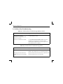
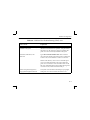
1
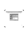
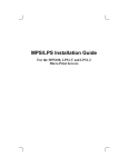
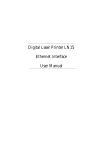
Print Server Installation Guide
For MPS1-T and MPS1-2 Ethernet Print Servers
and MPS100 Fast Ethernet Print Servers
The information in this guide may change without notice. The manufacturer assumes no responsibility for any
errors which may appear in this guide.
DEC, thickwire, thinwire, VMS, VT100, and ULTRIX are trademarks of Digital Equipment Corporation. UNIX
is a registered trademark of AT&T. Ethernet is a trademark of XEROX. NetWare is a trademark of Novell Corp.
AppleTalk, Chooser, and Macintosh are trademarks of Apple Computer Corp. Windows NT and Windows for
Workgroups are trademarks of Microsoft Corporation. PostScript is a trademark of Adobe Inc. Portions copyright
1989,1991,1992,1993 Regents of the University of California. All rights reserved. Used with permission.
Copyright 1998, Lantronix. All rights reserved. No part of the contents of this book may be transmitted or reproduced in any form or by any means without the written permission of Lantronix. Printed in the United States of
America.
The revision date for this manual is October 6, 1998.
Part Number: 900-146
Rev. A
WARNING
This equipment has been tested and found to comply with the limits for a Class A digital device pursuant to Part
15 of FCC Rules. These limits are designed to provide reasonable protection against such interference when operating in a commercial environment. This equipment generates, uses, and can radiate radio frequency energy, and
if not installed and used in accordance with this guide, may cause harmful interference to radio communications.
Operation of this equipment in a residential area is likely to cause interference in which case the user, at his or her
own expense, will be required to take whatever measures may be required to correct the interference.
Changes or modifications to this device not explicitly approved by Lantronix will void the user's authority to operate this device.
Cet appareil doit se soumettre avec la section 15 des statuts et règlements de FCC. Le fonctionnement est subjecté
aux conditions suivantes:
(1) Cet appareil ne doit pas causer une interférence malfaisante.
(2) Cet appareil doît accepter n'importé quelle interférence reìue qui peut causer une opération indésirable
Contents
1
Introduction
2
Installation
3
Getting Started
4
TCP/IP Configuration
5
NetWare Configuration
6
LAT Configuration
7
AppleTalk Configuration
8
LAN Manager/DLC Configuration
A
Contact Information
B
Troubleshooting
C
Pinouts
D
Updating Software
E
Specifications
F
Frequently-used Commands
Warranty Statement
Declaration of Conformity
Index
i
Introduction
1 - Introduction
The Lantronix Micro Print Server (MPS) is a multiprotocol print server that provides
shared network access to printers for a variety of network protocols and operating
systems. The MPS supports the AppleTalk (EtherTalk), Microsoft LAN Manager, Local
Area Transport (LAT), IPX (NetWare), and TCP/IP protocols. The MPS can queue
multiple pending jobs and service those jobs in the order that they are received from the
hosts. The Centronics parallel port on the back of the MPS is compatible with the
Hewlett-Packard Bitronics interface, which allows bi-directional communication on the
parallel port.
There are three MPS models which are the same except for the Ethernet interface used.
The MPS1-T has an RJ45 port for 10BASE-T connections, the MPS1-2 has a BNC
connector for 10BASE-2 connections, and the MPS100 can auto-negotiate between
10BASE-T and 100BASE-T media connected to its RJ45 port. The features, installation
process, and conÞguration procedures are the same.
NOTE: In this manual, all MPS models will be referred to as Òthe MPSÓ or
Òthe ServerÓ unless a distinction needs to be made between them.
1-1
Introduction
1.1 How to Use This Manual
This guide is structured as follows:
¥ Chapter 2, Installation, explains how to physically install the Server.
¥ Chapter 3, Getting Started, explains the minimum conÞguration needed to
operate the Server.
¥ Chapters 4 through 8 cover protocol-speciÞc setup needed to install print
queues and otherwise use the Server.
Read chapters 2 and 3 in order, then proceed to the protocol-speciÞc chapter that relates
to your network.
1-2
Installation
2 - Installation
2.1 Product Description
The front panel of the MPS has a Test button, LEDs, a power connector, and one of the
following Ethernet ports: a BNC connector for 10BASE-2 (MPS1-2), an RJ45 port for
10BASE-T (MPS1-T), or an RJ45 port for 10/100BASE-T (MPS100). The rear panel has a
Centronics connector.
“back”
Centronics Connector
LINK
AC
T
100
10/100BASE-T Port
TEST
MPS100
5VDC
“front”
The LINK LED is solid green when there is a valid Ethernet network connection. The
ACT (Activity) LED ßashes green or red when the server is in use. The 100 (100 MBit)
LED (MPS100 only) is solid green when a 100BASE-T network is connected.
2-1
Installation
The Test button serves two functions. When pressed brießy, it prints a test page. When
pressed for Þve seconds while plugging in the power cable, it returns the Server to its
factory default conÞguration.
2.2 Installation
The following diagram shows a properly-installed MPS:
PARALLEL PRINTER
➂
①
➁
100BASE-T
MPS100
To install the server, complete the following steps in order. Refer to the numbers in the
Þgure for help.
2-2
Installation
1.
Connect the MPS Centronics connector directly to your printerÕs connector.
2a. For MPS1-T and MPS100 models, connect a twisted pair Ethernet cable to the
MPS RJ45 connector.
2b. For MPS1-2 models, connect a thin coaxial Ethernet cable to the MPS BNC
connector.
3.
Attach one end of the power cable to the MPS; plug the other end into an
electrical outlet. Power will come on automatically.
NOTE: The LINK LED indicates a good network connection. The ACT LED gives
information about what the MPS is doing; for example, when code is being
downloaded as the unit boots, the LED will blink green quickly.
Allow 45 seconds for the unit to fully boot. The LINK LED will be lit if there is a
valid connection to the network, and the ACT LED should blink.
4.
Print a Test page by pressing the Test/Reset button.
NOTE: If the Test page does not print, refer to Appendix B, Troubleshooting.
5.
Install EZWebCon on your 32-bit Windows PC to conÞgure your Server. The
EZWebCon software is located on the CD-ROM. See EZWebCon ConÞguration on
page 3-2 for more information.
2-3
Getting Started
3 - Getting Started
It is important to consider the following points before logging into and conÞguring the
MPS:
¥ The MPS IP address must be conÞgured before any TCP/IP
functionality is available. (See Setting the IP Address on page 4-2.)
¥ There are two important passwords on the MPS: the privileged
password and the login password.
Changing any server, service, or port setting requires privileged user
status. The default privileged password is system.
The login password is required for remote console logins. The
default login password is access.
NOTE: If you would like to change either the privileged or login password,
either use EZWebCon or refer to the Print Server Reference Manual
located on the CD-ROM.
3-1
Getting Started
3.1 EZWebCon Configuration
The EZWebCon conÞguration software is the recommended way to conÞgure the MPS.
EZWebCon is a graphical user interface that guides Þrst time users through the initial
conÞguration process and allows experienced users to update and change any
conÞgurable parameters. There are two important things to note about EZWebCon:
¥ Your Server must have an IP address before EZWebCon can log into
it for conÞguration purposes. See Setting the IP Address on page 4-2
for instructions.
¥ EZWebCon requires a Java Virtual Machine (JVM) on the client.
Lantronix provides JVM installers for Solaris and 32-bit Windows
users, as well as source code and instructions for compiling it for use
on other systems.
The EZWebCon software is located on the distribution CD-ROM. All instructions for
installing EZWebCon are provided in the README Þle. For assistance once EZWebCon
is running, refer to the EZWebCon on-line help.
NOTE: EZWebCon is also available from the Lantronix FTP and BBS servers.
See Appendix D for more information about logging into the FTP and
BBS servers.
3-2
Getting Started
3.2 Incoming Logins
Incoming logins made via EZWebCon can be used to conÞgure the server. Incoming LAT
and TCP/IP logins can also be used.
Incoming Telnet is enabled by default to allow TCP/IP connections. To change this
setting, use the DeÞne Server Incoming command described in the Command Reference
chapter of the Print Server Reference Manual located on CD-ROM.
Incoming logins do not prompt for a login password; therefore, you may wish to disable
them. If it is undesirable to disable incoming logins, the Server can be conÞgured to
prompt for a password with the DeÞne Server Incoming Password Enabled command.
3.3 Services
With few exceptions, a service must be created before print queues can be conÞgured on
the MPS. A service is a resource accessible to network hosts. A Lantronix service is also
known as a remote printer name or remote queue name on many operating systems.
The following 3 default services are available once the Server has booted:
MPS_xxxxxx_TEXT
Used for text print jobs
MPS_xxxxxx_PCL
Used for binary print jobs, such as plotter or PCL Þles
MPS_xxxxxx_PS
Used for PostScript print jobs
3-3
Getting Started
If you need to modify a default service, see the Server ConÞguration chapter of the Print
Server Reference Manual located on the CD-ROM. Be sure to reboot after conÞguring
services so that the changes take effect.
3-4
TCP/IP Configuration
4 - TCP/IP Configuration
The EZWebCon conÞguration software is the easiest way to conÞgure the MPS. The
following sections cover IP address conÞguration and print conÞguration methods for
TCP/IP hosts.
NOTE: The Server needs an IP address before you can use EZWebCon. See
page 4-2 for instructions.
The MPS provides two major methods of printing via TCP/IP: Berkeley remote LPR and
RTEL host software.
Neither Windows for Workgroups nor Windows 95 support LPR directly; however, there
are third party solutions available. For more information about recommended peer-topeer printing solutions, see the Lantronix Windows 95 FAQ on the CD-ROM or the
Lantronix web site.
4-1
TCP/IP Configuration
4.1 Setting the IP Address
The MPS IP address must be conÞgured before any TCP/IP functionality is available.
To set the IP address, use one of the following methods: EZWebCon; a directed Ping
packet; a DHCP, BOOTP, or RARP reply; or commands entered at the command line
(Local>) interface.
4.1.1 Using EZWebCon
The MPS must have an IP address before you can log into it using EZWebCon. To assign
the IP address from EZWebCon:
1.
Start EZWebCon. Instructions for installing, running, and using EZWebCon can be
found on the distribution CD-ROM.
2.
Click on the Lantronix logo menu in the bottom left corner of the EZWebCon window, then select Assign IP Address to Server.
3.
Fill in the following information:
A. The last three bytes of the MPSÕs hardware address. The hardware address
is printed on the bottom of the Server.
B.
4-2
The desired IP address.
TCP/IP Configuration
C.
The subnet, if you wish to use a subnet other than the default.
D. The IP address of the TFTP server you wish to use, if desired.
4.
Click OK.
5.
Cycle power on the server. EZWebCon will let you know whether the conÞguration was successful.
4.1.2 Using a Directed Ping Packet
The ARP/ping method is available under UNIX, Windows 95, and Windows NT. If the
MPS has no IP address, it will set its address from the Þrst directed IP packet it receives.
NOTE: The ARP/ping method only works during the first two minutes of
MPS operation. After two minutes, an alternate method must be used
or the MPS must be rebooted.
On a UNIX host, create an entry in the hostÕs ARP table and substitute the intended IP
address and the hardware address of the server, then ping the server. This process
typically requires superuser privileges.
# arp -s 192.0.1.228 00:80:a3:xx:xx:xx
% ping 192.0.1.228
4-3
TCP/IP Configuration
In order for the ARP command to work on Windows, the ARP table on the PC must have
at least one IP address deÞned other than its own. If the ARP table is empty, the
command will return an error message. Type ARP -A at the DOS command prompt to
verify that there is at least one entry in the ARP table.
If there is no other entry beside the local machine, ping another IP machine on your
network to build the ARP table. This has to be a host other than the machine that you're
working on. Once there is at least one entry in the ARP table, use the following
commands to ARP the IP address to the MPS and make the MPS acknowledge the IP
assignment.
C:\ ARP -S 192.0.1.228 00-80-A3-XX-XX-XX
C:\ PING 192.0.1.228
NOTE: There should be replies from the IP address if the ARP command
worked.
When the MPS receives the ping packet, it will notice that its IP address is not set and
will send out broadcasts to see if another node is using the speciÞed address. If no
duplicate is found, the server will use the IP address and will respond to the ping packet.
The MPS will not save the learned IP address permanently; this procedure is intended as
a temporary measure to enable EZWebCon to communicate with the server, or allow an
4-4
TCP/IP Configuration
administrator to Telnet into the MPS. Once logged in, the administrator can enter the
Change IPaddress command to make the address permanent.
% telnet 192.0.1.228
Trying 192.0.1.228
Lantronix Version n.n/n (yymmdd)
Type Help at the ‘Local_>’ prompt for assistance.
Enter Username> gopher
Local> SET PRIVILEGED
Password> system (not echoed)
Local>> DEFINE IPADDRESS 192.0.1.228
Any host wishing to access the MPS will have to be told the MPSÕs IP address. This is
typically conÞgured in the unix Þle /etc/hosts or via a nameserver. Refer to the hostÕs
documentation for additional information.
4-5
TCP/IP Configuration
4.1.3 Using a DHCP, BOOTP, or RARP Reply
At boot time a host-based DHCP, BOOTP, or RARP server can respond to an MPS request
for an available IP address. For information about conÞguring the DHCP, BOOTP, or
RARP server, see your host documentation.
4.1.4 Using the Command Line Interface
1.
Connect to the serial port (Port 1) using a terminal emulation program. The serial
settings should be 9600 baud, 8 bits, 1 stop bit, no parity.
2.
Become the privileged user and enter the new IP address.
Local> SET PRIVILEGED
Password> system (not echoed)
Local>> DEFINE SERVER IPADDRESS 192.0.1.201
4-6
TCP/IP Configuration
4.2 Notes About LPR
There are four important things to note about the LPR printing method:
1.
Because of the way the LPR protocol is typically implemented on the host, the
processing options and banner page are sent after the job data itself. The MPS
will print a banner page at the end of a job, and cannot support most of the LPR
options. If it is necessary to have the banner page at the beginning of the printout,
install and use the RTEL software. If banners are not needed, they can be disabled.
2.
The MPS cannot print multiple copies of the print job when using the Ò-#nÓ lpr
option.
3.
If two print queues on the host refer to two services on the same MPS, they must
use separate spooling directories.
4.
No special purpose input or output Þlters can be used when printing via LPR. If
this functionality is necessary, use the named pipe interface program in the RTEL
print queue conÞguration software.
4-7
TCP/IP Configuration
4.3 LPR on Windows NT 4.x
NOTE: This installation assumes that TCP/IP, Simple TCP/IP, and Microsoft
TCP/IP printing have been installed on the Windows NT host.
4-8
1.
In the Control Panel, double-click the Printers icon.
2.
Double-click the Add Printer icon.
3.
In the window that appears, choose My computer and click Next.
TCP/IP Configuration
4.
Select the Add Port button and click Next.
4-9
TCP/IP Configuration
5.
Select LPR Port.
NOTE: If LPR Port is not an option, refer to your Windows NT documentation for
instructions on installing the ÒMicrosoft TCP/IP PrintingÓ service.
6.
4 - 10
Enter the name or IP address of your MPS on the Þrst line, and enter the name of
your MPS print service on the second line.
TCP/IP Configuration
7.
Select the manufacturer and printer type.
4 - 11
TCP/IP Configuration
8.
4 - 12
Enter the queue name.
TCP/IP Configuration
9.
If applicable, choose Shared and select the type of operating system that the
printer will be working with. (First conÞrm that the print queue is working.)
4 - 13
TCP/IP Configuration
10. Test the printer.
4 - 14
TCP/IP Configuration
4.4 LPR on UNIX Hosts
The Berkeley remote printing system is supported on many machines, and is simple to
conÞgure.
This section describes how to conÞgure LPR print queues on generic UNIX hosts such as
SUN hosts. There are slight variations in LPR conÞguration for AIX, HP, and SCO hosts,
as will be explained in the following sections.
1.
Install a print queue on your host by adding the MPS name and IP address to the
/etc/hosts Þle:
192.0.1.83
2.
MPS_xxxxxx
Add the host print queue to the /etc/printcap Þle:
mps_prt|Printer on LAB MPS:\
:rm=MPS_xxxxxx:\
:rp=MPS_xxxxxx_TEXT:\
:sd=/usr/spool/lpd/mps_prt:
The punctuation shown is required, and no extra spaces should be added.
4 - 15
TCP/IP Configuration
This will create a host queue named mps_prt. The rm parameter is the name of the
MPS in the host's address file, the rp parameter is the name of the service as it exists
on the MPS, and the sd parameter specifies the name of a directory used to hold
temporary spooling files.
3.
Create a world-writable spooling directory using the mkdir command.
# mkdir /usr/spool/lpd/mps_prt
# chmod 777 /usr/spool/lpd/mps_prt
4.
If desired, use the mx option to allow unlimited size Þles to be printed and the sh
option to prevent header pages from being generated. See the host's documentation or man pages for more information on the format of the printcap Þle and how
to create the spool directory.
5.
Print to the queue using normal lpr commands:
% lpr -Pmps_prt /etc/hosts
4 - 16
TCP/IP Configuration
4.4.1 LPR on AIX Hosts
LPR has only been tested on AIX versions 3.2 and higher. The System Management
Interface Tool (SMIT) allows you to enable LPD printing and create print queues.
To create a print queue:
1.
At the host prompt type smit.
2.
Choose Print Spooling.
3.
Choose Manage Print Server and Start the Print Server Subsystem (lpd
daemon).
4.
In the Start the Print Server Subsystem dialog box, type both in the Þrst Þeld.
The message ÒThe lpd subsystem has been startedÓ will appear. Click Done.
To add a print queue:
1.
From the main window choose Print Spooling.
2.
Choose Manage Print Server and Manage Print Queues.
3.
Choose Add a print queue.
4.
From the dialog box that appears choose remote.
4 - 17
TCP/IP Configuration
5.
From the next dialog box choose Remote Printing.
6.
The Add a Standard Remote Print Queue dialog box will appear. Enter the
following information.
Ð
The name of the print queue,
Ð
The name of the MPS unit,
Ð
The name of the MPS service,
Ð
The type of print spooler on the remote server, and
Ð
A description of the printer on the remote server.
A dialog box will appear with the message ÒAdded print queue mps_prt.Ó
NOTE: If you are unable to use SMIT, see the Print Server Reference Manual
for UNIX commands for setting up print queues.
7.
Print to the queue using normal lp syntax.
% lp -dmps_prt filename
4 - 18
TCP/IP Configuration
4.4.2 LPR on HP Hosts
The System Administration Manager (SAM) allows you to create print queues.
NOTE: If you are unable to use SAM, the Print Server Reference Manual
located on the CD-ROM described UNIX commands that can be used
to set up print queues.
To create a print queue:
1.
At the HP prompt type sam.
2.
From the main application window choose Printers and Plotters.
3.
Choose Printers/Plotters from the Printers and Plotters window.
4.
In the pull-down menu select Remote Printer/Plotter from the Actions menu.
5.
The Add Remote Printer window will appear. SAM will prompt you for:
Ð
The printer name (the name of the print queue),
Ð
The remote system name (the MPS name),
Ð
The remote printer name (the MPS service),
Ð
The remote cancel model, and
Ð
The remote status model.
4 - 19
TCP/IP Configuration
NOTE: Printer names on HP hosts are limited to 13 characters. The MPS text
service name will be too long, so you will have to rename the Server.
4.4.3 LPR on SCO UNIX Hosts
LPR is supported in SCO V3.2 release 4 with TCP/IP Version 1.2 and greater.
To conÞgure a print queue using LPR:
1.
Issue the mkdev rlp command. This will install the Berkeley remote printing Þles
and executable programs.
NOTE: The mkdev rlp command should only be issued once, or serious problems
will occur. If this happens, contact SCO technical support.
You can print to this queue using normal lp syntax once the remote printer is set
up.
To create a remote printer:
1.
Issue the rlpconf command.
2.
Answer the questions that follow. See the Þgure on the next page for more
information.
4 - 20
TCP/IP Configuration
Remote Printing Configuration
Enter information for remote printers or local printers accepting remote
printing requests
Please enter the printer name (q to quit): backupprinter
Is printer backupprinter a remote printer or a local printer? (r/l) r
Please enter the name of the remote host that backupprinter is attached
to: MPS_xxxxxx
The backupprinter is connected to host MPS_xxxxxx.
Is this correct? (y/n) y
Would you like this to be the sys.default printer? (y/n) y
Make sure your hostname appears in MPS_PRT’s /etc/hosts.equivor or /etc/
hosts:lpd file.
Make sure backupprinter appears in /etc/printcap (in BSD format).
Make sure backupprinter has a spool directory on MPS_PRT.
Putting the printer in printer description file and creating spool directory... done
Updating LP information... done
The printer name is your MPS service name. The remote host name is the name of
your MPS as it is listed in your hosts file.
During initial configuration, the queue name must be the same as the remote
printer name. However, you may change the queue name later by manually
editing the printcap file.
4 - 21
TCP/IP Configuration
4.5 RTEL Functionality
If the LPR method of printing is not adequate for an application (for example, if you
need banners before jobs, or more ßexibility), conÞgure the Lantronix-supplied RTEL
software on the host. After installing the software conÞguring the connections to the
MPS, you can use normal UNIX print commands and queue utilities such as lpc and
lpstat.
NOTE: RTEL binaries are provided for many systems. Source code is also provided for use on non-supported systems.
To print to the MPS using special formatting or using third-party software packages,
you may have to create Òprint pipesÓ on the host. The RTEL software provides this
functionality by providing a UNIX named-pipe interface.
To recreate the RTEL source Þles:
1.
Copy the Þle RTEL_SRC.TAR from the distribution CD-ROM to the UNIX host.
Ensure that a binary copy is performed.
2.
Untar the archive.
3.
See the README Þles in the created directories that describe the contents of the
RTEL distribution and man pages that describe the actual software functionality.
4 - 22
TCP/IP Configuration
4.6 Unix Host Troubleshooting
Table 4-1: TCP Troubleshooting
Area to Check
Explanation
The Server IP address and name are
entered in the host Þle
Telnet to the Server using the name in the host Þle and
verify that the Server name is resolvable and that the
Server is reachable via the network.
Jobs that appear in the host queue
reach the Server
From within the LPC administrative utility, enter
these commands to clear and reset the host queue:
abort queue_name
clear queue_name
enable queue_name
start queue_name.
4 - 23
NetWare Configuration
5 - NetWare Configuration
The EZWebCon conÞguration software is the easiest way to conÞgure the MPS. The
following sections cover print conÞguration methods for NetWare hosts.
NOTE: The Server needs an IP address before you can use EZWebCon. See
the Setting the IP Address section on page 4-2 for instructions.
This chapter explains creating NDS print queues with NetWare Administrator and with
the PCONSOLE Quick Setup option. To create NDS print queues, you must be running
NetWare version 4.x with NDS capabilities.
If you are running NetWare versions 2.x, 3.x, or version 4.x with bindery emulation, you
may conÞgure bindery print queues using QINST (bindery only) or PCONSOLE. For
more information, see the NetWare chapter of the Print Server Reference Manual, located
on CD-ROM.
5-1
NetWare Configuration
5.1 Obtaining an NDS License
If you wish to create NDS print queues, you must read and complete an NDS registration
form via one of the following methods:
¥ Using a forms-capable Internet browser, navigate to the Lantronix World
Wide Web site (located at URL http://www.lantronix.com) and Þnd the
NDS Registration link.
¥ Send email to [email protected]. You will receive a blank registration
form that can be completed and returned to Lantronix.
¥ If you donÕt have Internet access, contact a Lantronix Technical Support representative for assistance. Contact information is provided in Appendix A.
1.
License NDS on your server using the string obtained from Lantronix.
Local>> DEFINE PROTOCOL NETWARE DSLICENSE licensestring
2.
DeÞne the directory service tree in which the Server is located.
Local>> DEFINE PROTOCOL NETWARE DSTREE foodco
5-2
NetWare Configuration
NOTE: For an explanation of the structure of the NetWare Directory Service
tree, see your host documentation.
3.
DeÞne the directory service context in which the Server is located.
Local>> DEFINE PROTOCOL NETWARE DSCONTEXT ou=kiwi.ou=exotic.o=fruit
4.
Enter the List Protocol NetWare Access command to ensure that at least one of
the Þle servers in the directory service tree is in the access list.
5.
If desired Þle server is not in the access list, add it.
Local>> DEFINE PROTOCOL NETWARE ACCESS fileserver
6.
Reboot the MPS.
Local>> INITIALIZE DELAY 0
5-3
NetWare Configuration
5.2 Creating Print Queues Using NetWare Administrator Quick Setup
The NetWare Administrator management utility allows you to manage network
resources, such as queue-based print services, in a tree structure. You can either use the
Quick Setup option or individually create printing-related objects.
To create a print queue with the Quick Setup option.
NOTE: NetWare Administrator can be used for both NDS and bindery print queues.
5-4
1.
Start NetWare Administrator.
2.
In the Directory Tree windows, select the context in which to install the printer.
3.
From the Menu Bar, select Tools: Print Services Quick Setup.
4.
In the Print Server Name Þeld, enter the name of your Lantronix server (viewable
by entering the Show Server command at the Local> prompt).
5.
In the Printer Name Þeld, enter the name of the desired print service conÞgured on
your Lantronix server.
6.
In the Print Queue Name Þeld, enter the name of the print queue to create. The
name should be meaningful to you; it will not affect Server conÞguration.
7.
Click Create.
8.
Reboot the MPS.
NetWare Configuration
5.3 Creating NDS Print Queues Using PCONSOLE
1.
Log in as Admin on the Þle server you will be changing.
2.
Type PCONSOLE at the X: prompt to start the utility.
For example, if your file server is mapped to the F: drive, you would use the F:
prompt.
3.
From the main menu choose Quick Set-Up.
4.
PCONSOLE will prompt you for information with which to conÞgure the print
queue.
The print server name is the name of your MPS (MPS_xxxxxx). The new printer
name is the service name (for example, MPS_xxxxxx_Text). The new print queue
can be any name. The print queue volume is the name of the file server from which
the printer receives print requests. The remaining fields can be left in their default
settings.
NOTE: In the above text, xxxxxx represents the last 6 digits of your MPSÕs
hardware address. The hardware address is printed on the unitÕs label.
5.
Press the F10 key to save the print queue information.
6.
Reboot the MPS.
5-5
NetWare Configuration
5.4 NetWare Host Troubleshooting
Table 5-1: NetWare Host Troubleshooting (Bindery Mode)
Area to Check
Explanation
The print server names in
PCONSOLE match the MPS name
and its service name?
Use PCONSOLE to check.
The ServerÕs NetWare access table
Use the Show Protocols NetWare Access command.
Scanning too many Þle servers can cause a delay
between jobs.ConÞgure the access list to only scan for
jobs on the Þle servers of interest.
Table 5-2: NetWare Host Troubleshooting (NDS)
Area to Check
Explanation
The ServerÕs NetWare access table
Use the Show Protocols NetWare Access command. By
default, only local Þle servers are scanned for queues.
The login password on the Server
and the queue password on the Þle
server
The passwords must match or the Server will not be able
to log into the Þle servers to scan for jobs.
5-6
NetWare Configuration
Table 5-2: NetWare Host Troubleshooting (NDS), cont.
Area to Check
Explanation
The print server has successfully
attached to the queue
Type NETSTAT at the Local> prompt. This will display
information about Þleservers, printers, and queues that
the print server has found. If a queue is in JobPoll, the
print server has successfully attached to the queue.
The DSTree, DSContext, and
DSLicense
Type Show Protocol NetWare NDS. This command
shows the tree and the context that you have conÞgured,
a failure code, and an NDS error code for each server.
DSTree is the directory service tree on which the print
server is located. DSContext is the context where the
print server is located; it must match the context on the
Þle server (The DSContext must be of the following form:
ou=fruit.o=exotic). DSLicensed should be yes.
Printer and queue changes have
propagated through the NDS tree
It may take a few minutes for the changes to propagate.
If the print server doesnÕt attach, reboot the server.
5-7
NetWare Configuration
Table 5-3: NDS Errors from the File Server
Failure code
Failure code meaning
0xfffffda7
Object could not be found in the Check the print server name, DSContext, and
given context
DSTree to make sure that the printer server is set
up correctly with PCONSOLE.
0xfffffda5
The requested attribute could
not be found
Use PCONSOLE to make sure that the print
server has associated printers and that the
printers have associated queues.
0xfffffd69
DS Database is locked
An administrator is probably updating the
database. Wait a few minutes and issue the Set
Protocol NetWare Reset command.
0xfffffd63
The password is invalid
The password for the print server object under
PCONSOLE must match the ServerÕs login
password. If the login password on the Server is
left as the default (access), there should be no
password for the print server object.
0xfffffd54
Secure NCP violation
Turn down the NCP packet signature level so that
it is not required from the server.
5-8
Remedy
NetWare Configuration
Table 5-4: NDS Printing Errors
Bit
Failure Code Meaning
Remedy
1
Server out of memory
Turn the Server off, wait a few seconds, and turn it back on.
Disable unused protocols and/or remove Þleservers without
print queues from the NetWare access list.
2, 3
Unexpected response
from Þle server
Report the problem to Lantronix Technical Support.
4
No printers found for the
Server
Ensure that there are printers for the print server, and the
printer names match the service names on the print server.
5
No printer queue found
Ensure that the printers have associated queues.
6
Login failed
Ensure there is a print server object conÞgured with the same
name as the Server.
7
Authentication failed
Ensure the Server login password is the same as the print server
object password. If the Server is using the default password
(access), there should be no print server object password.
8
Server cannot attach to
queue
Check the NDS partitions, replicas, and volumes to ensure the
Þle server where the queue lives has the correct information
about the Server and printers.
5-9
LAT Configuration
6 - LAT Configuration
The EZWebCon conÞguration software is the easiest way to conÞgure the MPS. The
following sections cover print conÞguration methods for LAT hosts.
NOTE: The Server needs an IP address before you can use EZWebCon. See
the Setting the IP Address section on page 4-2 for instructions.
LAT print queues can be created by printing to a port or printing to a service. Printing
directly to a port requires no MPS conÞguration.
NOTE: Printing directly to a port is the easiest method for printing to the
MPS. If you would like instructions for printing to a service, see the
Print Server Reference Manual on the CD-ROM.
6.1 Printing Directly to a Port
1.
Create a LAT application port that references the Server port.
$ RUN SYS$SYSTEM:LATCP
LATCP> CREATE PORT LTAnnn/APPLICATION
LATCP> SET PORT LTAnnn/NODE=MPS_xxxxxx/PORT=Port_n
LATCP> EXIT
6-1
LAT Configuration
2.
Create and start a print queue that uses the LAT application port.
$ INITIALIZE/QUEUE/START/ON=LTAnnn:/PROCESSOR=LATSYM
/RETAIN=ERROR queue_name
3.
Add the commands to the SYS$MANAGER:LAT$STARTUP.COM Þle so the
required LAT devices will be recreated after each host reboot.
NOTE: LAT terminal device characteristics may have to be changed to correctly
print certain files. See your VMS documentation for more information.
4.
Print to the queue.
$ PRINT/QUEUE=queue_name filename.txt
6-2
LAT Configuration
6.1.1 LAT Host Troubleshooting
By default, the LAT error message codes on the host are not translated into text error
messages. If a LAT job fails and appears in the queue with an eight-digit hex result code,
the code can be translated by issuing the following commands:
$ SHOW QUEUE/FULL/ALL queue_name
(note the error code nnnnnnnn)
$ SET MESSAGE SYS$MESSAGE:NETWRKMSG.EXE
$ EXIT %Xnnnnnnnn
Table 6-1: Troubleshooting LAT ConÞgurations Using a Port
Area to check
Explanation
The speciÞed node name matches the
ServerÕs node name
Use the Show Server command.
The speciÞed port name matches the portÕs
name
Use the List Port 1 command.
6-3
AppleTalk Configuration
7 - AppleTalk Configuration
The EZWebCon conÞguration software is the easiest way to conÞgure the MPS. The
following sections cover print conÞguration methods for AppleTalk hosts.
NOTE: The Server needs an IP address before you can use EZWebCon. See
the Setting the IP Address section on page 4-2 for instructions.
NOTE: Macintoshes that do not support EtherTalk will need either an Ethernet card or a LocalTalk-to-EtherTalk router to use the MPS.
7.1 Bitronics
The MPS advertises its printer as a LaserWriter. Therefore, printing from a Macintosh is
only possible with a PostScript printer and bi-directional communication between the
MPS and that printer.
NOTE: MacOS 8.1 can also print via LPD. See the Print Server Reference Manual
located on CD-ROM for configuration instructions.
The MPS supports the Bitronics interface, an extension to the standard Centronics
interface. Printers that support Bitronics allow bi-directional communication via the
parallel port. To enable Bitronics on the MPS parallel port, use the DeÞne Port 1
Bitronics Enabled command.
7-1
AppleTalk Configuration
7.2 Macintosh Services
Before attempting to print from a Macintosh, ensure that AppleTalk and PostScript are
both enabled on at least one service. Once the service is conÞgured, it will appear in the
Chooser in the same zone as the MPS. Select the service in the Chooser and complete the
appropriate setup options. Then close the Chooser window and print a test page of text
to the Macintosh service.
7.3 AppleTalk Zones
If there is a router on the network, the MPS will appear in the default zone speciÞed by
the router. To change the default zone use the DeÞne Protocol AppleTalk Zone
command.
If the MPS is attached to a network without an AppleTalk router, all AppleTalk devices
(including the MPS) will appear in the default zone in the Chooser.
NOTE: If no router is present on the network, the MPS will not accept AppleTalk
print jobs for 60 seconds after booting.
7-2
AppleTalk Configuration
7.3.1 AppleTalk Host Troubleshooting
Table 7-1: AppleTalk Host Troubleshooting
Area to Check
Explanation
The printer is available to be selected
in the Chooser
Make sure the printer is in the right zone.
Bidirectional communication
Lock the printer in PostScript mode and issue the
Test Service PostScript Count n command. This
sends a job to the printer and waits for the response.
7-3
LAN Manager/DLC Configuration
8 - LAN Manager/DLC Configuration
The EZWebCon conÞguration software is the easiest way to conÞgure the MPS. This
chapter explains DLC conÞguration for Windows NT 4.x hosts. Windows 95 does not
support DLC printing (see Chapter 4, TCP/IP ConÞguration, for more information).
NOTE: The Server needs an IP address before you can use EZWebCon. See
the Setting the IP Address section on page 4-2 for instructions.
NOTE: Printing using an LPD client is the preferred method for sending
print jobs to the MPS. To print using the TCP/IP protocol see the
Using the Command Line Interface section on page 4-8.
8.1 DLC Configuration
8.1.1 Server Configuration
To use the DLC protocol, you must have one service with the DLC characteristic enabled.
Use the DeÞne Service servicename DLC Enabled command. The DLC characteristic
may be associated with only one service on a given MPS.
8-1
LAN Manager/DLC Configuration
8.1.2 Host Configuration
To send print jobs from a Windows NT host to the MPS, add the MPS as a Windows NT
printer.
1.
Double-click the Printers icon in the Control Panel.
2.
Double-click the Add Printer icon.
3.
In the window that appears select My Computer and click Next.
4.
Select the Add Port button.
5.
Select Hewlett-Packard Network Port and click New Port.
If Hewlett-Packard port is not one of the available options, you must install DLC
printing from your Windows NT system disks. DLC is not installed by default.
6.
Enter the ServerÕs hardware address. It is printed on the ServerÕs bottom label.
7.
Select Job-based.
8.
Select the manufacturer and printer type.
9.
Enter the queue name.
10. If applicable, choose Shared and select the operating system the printer will be
working with. (First conÞrm that the print queue is working.)
11. Test the printer.
8-2
Contact Information
A - Contact Information
If you are experiencing an error that is not listed in the Troubleshooting appendix or if you
are unable to Þx the error, contact your dealer or Lantronix Technical Support at
(800) 422-7044 or (949) 453-3990. Technical Support is also available via Internet email
at [email protected].
When you report a problem, please provide the following information:
¥ Your name, and your company name, address, and phone number
¥ Lantronix server model number
¥ Lantronix server serial number
¥ Software version (use the Show Server command to display)
¥ Network conÞguration, including the information from a Netstat
command
¥ Description of the problem
¥ Debug report (stack dump), if applicable
¥ Status of the unit when the problem occurred (please try to include
information on user and network activity at the time of the problem)
A-1
Contact Information
LANtronix
15353 Barranca Parkway, Irvine, CA 92618 USA
Phone: 949/453-3990
Fax: 949/453-3995
World Wide Web: http://www.lantronix.com
North American Direct Sales: 800/422-7055
North American Reseller Sales: 800/422-7015
North American Sales Fax: 949/450-7232
Internet: [email protected]
International Sales: 949/450-7227
International Sales Fax: 949/450-7231
Internet: [email protected]
Technical Support: 800/422-7044 or 949/453-3990
Technical Support Fax: 949/450-7226
Internet: [email protected]
A-2
Troubleshooting
B - Troubleshooting
B.1 Power-Up Troubleshooting
There are several possible error situations if the LEDs do not ßash.
Table B-1: Error Messages
Message
Diagnosis/Remedy
Power-up diagnostic failure (hardware
failure)
Note which LED is blinking and its color, then contact
your dealer or Lantronix Technical Support.
The Server boots but does not try to
load the Flash ROM code
Press the Test button. A brief description of the problem
will be queued to the parallel port and printed.
Network Error: The ACT LED will blink
yellow 2-3 times per second
A. Make sure the Ethernet network cable is properly
connected and reboot the server.
B. If option A fails to resolve the problem, reload Flash
ROM. See Appendix D.
B-1
Troubleshooting
B.2 Printing Problems
Table B-2: General Printing Problems
Area to Check
Explanation
Physical connection
To test a non-PostScript printer use the Test Port 1 Count
100 command. This command will send 100 lines of test
data out the parallel port.
Service characteristics
Use the Show Service Local Characteristics command
from the ServerÕs Local> prompt to see if the desired
service is available and to verify that the appropriate
protocols are enabled on the service.
The IP address
The IP address must be unique on the network. Many
problems will occur when there are duplicate IP
addresses on the network.
Queue Status and Port counters
Use the Monitor Queue command to ensure queue
entries appear in the job list. If an entry does not appear,
refer to the appropriate host section in this Appendix.
Use the Monitor Port 1 Counters command to verify
that the counter is incrementing with each job. If it is not,
verify the connection between the Server and the printer.
B-2
Troubleshooting
B.3 BOOTP Troubleshooting
If the BOOTP request is failing and you have conÞgured your host to respond to the
request, check these areas:
Table B-3: BOOTP Troubleshooting
Area to Check
Explanation
BOOTP is in your systemÕs
/etc/services Þle
BOOTP must be an uncommented line in the /etc/services
Þle.
The Server is in the loadhostÕs
/etc/hosts Þle
The Server must be in this Þle for the host to answer a
BOOTP or TFTP request.
The download Þle is in the correct
directory and is world-readable
The download Þle must be in the correct directory and
world-readable. Specify the complete pathname for the
download Þle in the BOOTP conÞguration Þle or, a add a
default pathname to the download Þlename.
The Server and host are in the
same IP network
Some hosts will not allow BOOTP replies across IP networks.
Either use a host running a different operating system or put
the Server in the same IP network as the host.
B-3
Troubleshooting
B.4 DHCP Troubleshooting
Table B-4: DHCP Troubleshooting
Area to Check
Explanation
DHCP is enabled on the Server.
Use the DeÞne Server DHCP Enabled command.
If you manually enter an IP address, DHCP is
automatically disabled.
Make sure the DHCP server is
operational.
Check to see that the DHCP server is on and is
functioning correctly.
Did the Server get its IP address from
the DHCP server?
Refer to the DHCP Manager on your DHCP server for
information about addresses currently in use. If the
DHCP server does not list your ServerÕs IP address,
there may be a problem.
B-4
Troubleshooting
B.5 RARP Troubleshooting
Table B-5: RARP Troubleshooting
Area to Check
Explanation
The ServerÕs name and hardware
address in the hostÕs /etc/ethers Þle
The ServerÕs name and hardware address must be in
this Þle for the host to answer a RARP request.
The ServerÕs name and IP address in
the /etc/hosts Þle
The ServerÕs name and IP address must be in this Þle
for the host to answer a RARP request.
The operating system
Many operating systems do not start a RARP server at
boot time. Check the hostÕs RARPD documentation
for details, or use the ps command to see if there is a
RARPD process running.
B-5
Troubleshooting
B.6 PostScript Problems
PostScript printers will silently abort jobs if they detect an error.
Table B-6: PostScript Troubleshooting
Area to Check
Explanation
The Server is communicating
with the printer
To test a PostScript printer use the Test Port 1 PostScript Count
2. This command will send 2 pages of PostScript data out the
parallel port. Watch the indicators on the printer to verify that
the Server is communicating with the printer.
If the printer is capable of bidirectional communication, use the
Test Service MPS_xxxxxx_PS PostScript Count 5 command.
This will transfer data both to and from the printer.
Autoselection must be disabled and the printer must be
conÞgured as a PostScript printer for this test to succeed.
The printer is conÞgured to
use 8-bit characters
If special characters or bitmaps are not printing correctly, the
printer may be incorrectly conÞgured to use 7-bit characters.
Service Characteristics
Issue the Show Service Characteristics command. If the service
rating is zero, the parallel port is in use. Verify that the
PostScript characteristic and appropriate protocols have been
enabled on the service.
B-6
Troubleshooting
Table B-6: PostScript Troubleshooting, cont.
Area to Check
Explanation
Port Counters
If PostScript jobs appear to print but nothing comes out of the
printer, verify the amount of data sent from the host. Issue the
appropriate print command from the host system. After the job
has completed, use the Show Port 1 Counters command.
The bytes output value should be approximately 171 bytes
greater than the size of the Þle on the host system. These
numbers are only approximate, but will show that data is
ßowing to the printer.
B.6.1 Bitmap Graphics
If Þles that contain embedded bitmap graphics print incorrectly, it is because the bitmaps
are being sent as actual binary data and binary data cannot be printed via serial or
parallel interfaces.
Most major application packages have provisions to print using either Òbinary
postscriptÓ (for printers connected to the network via LocalTalk) or Òhex postscriptÓ (for
printers connected to the network via a serial port or parallel port). If your application
does not have this provision, ask the application vendor for an upgrade version or
ÒpatchÓ that will add the Òhex postscriptÓ function.
B-7
Pinouts
C - Pinouts
C.1 Parallel Information
Lantronix uses standard Centronics parallel connectors.
For optimum performance of your Server, Lantronix recommends the use of high quality
parallel cables. Choose one of the following:
¥ A Lantronix parallel port cable, part number #500-011 (6 feet).
¥ Any other brand of IEEE Std 1284-1994 compliant cable. Compliant
cables can easily be identiÞed by the permanent label ÒIEEE Std
1284-1994 compliantÓ on the cable itself.
NOTE: Non-compliant cables have the same type of connectors but different
electrical characteristics.
C-1
Updating Software
D - Updating Software
Current software Þles are available on the distribution CD. Software updates and release
notes for the Server can be downloaded directly from the Lantronix development
systems in one of three ways: via the Lantronix World Wide Web site located at
http://www.lantronix.com, using anonymous FTP through the Internet, and via dial-up
modem.
D.1 Updating Via the Web
The latest version of MPS.SYS can be downloaded from the Lantronix Web site. The
following instructions will lead you through the web site to the software Þle.
1.
On the home page, http://www.lantronix.com, click on Free Software Updates.
2.
From the directory that appears, choose pub/.
3.
From the resulting directory, choose the server acronym.
4.
From the resulting directory, choose the software volume.
5.
From the Þnal directory, choose MPS.SYS.
NOTE: As a result of Netscape NavigatorÕs configuration, clicking on the software
name will not allow you to download the file. You must save the file as a
source document to your host.
D-1
Updating Software
D.2 Updating Using FTP
The server software resides on the Lantronix FTP server (ftp.lantronix.com). Most of
these Þles are binary data, so the binary option must be used to transfer the Þles. All
released Þles are in the pub directory. Always download the README Þle in the pub
directory before downloading anything else; it contains a directory of available versions.
To log into the FTP server, enter a username of anonymous and enter your full email
address as the password. The following text will be displayed:
230-Welcome to the Lantronix FTP Server.
230230-IMPORTANT: Please get the README file before proceeding.
230-IMPORTANT: Set BINARY mode before transferring executables.
220230-Direct questions to [email protected] or 1.800.422.7044
230-Questions about this ftp account only to [email protected]
230230 Guest login ok, access restrictions apply.
Remote system type is UNIX. [your type will be displayed here]
Using binary mode to transfer files.
ftp>
D-2
Updating Software
D.3 Updating Using the BBS
The Lantronix system uses high speed modems for the physical connection and allows
Þle transfers using KERMIT, xmodem, ymodem, and zmodem. The modem phone
number is (949) 367-1051. The account name is ets and the password is server.
Remember that the download Þles (MPS.SYS) and executable images are image data and
should only be transferred in binary mode, otherwise the Þles will be corrupted.
SunOS UNIX (nexus)
login: ets
Password: server (not echoed)
Last login: Mon Jun 5 13:21:13 from company.com
SunOS Release 4.1.3_U1 (NEXUS) #2: Fri Dec 2 10:08:39 PST 1997
Welcome to the Lantronix BBS. Type ‘h’ for help
userid (‘new’ for new user): new
Welcome, new user! Enter a userid, 1-12 characters, no spaces.
Userid: bob
Enter Passwd: platypus (not echoed)
Confirm Passwd: platypus (not echoed)
User Name: bob
Terminal type (default=vt100):
Email address, if any: [email protected]
--CONTINUED NEXT PAGE-D-3
Updating Software
Welcome to the “NEW” Lantronix Bulletin Board System.
To access the files menu, type ‘f’ at the main menu.
At the files menu, type ‘p’ to select a download protocol
(a=ascii, k=kermit, x=xmodem, y=ymodem, z=zmodem)
At the files menu, type ‘l’ to list available software directories.
Select the board name by entering its number.
At any menu, press ‘h’ to receive additional help.
Press [Return] to continue:
D.4 Reloading Software
The Server stores software in Flash ROM to control the initialization process, operation,
and command processing. The contents of Flash ROM can be updated by downloading a
new version of the operational software via NetWare, TCP/IP, or MOP. Regardless of
which protocol is used to update Flash ROM, the following points are important:
¥ The Flash ROM software is contained in a Þle called MPS.SYS. The
name should not be changed.
¥ The download Þle should be world-readable on the host.
¥ There is a sixteen character length limit for the path name.
¥ There is a twelve character limit for the Þlename.
D-4
Updating Software
¥ DeÞne commands must be used because Set conÞgurations are
cleared when the Server boots. Use the List Server Boot command
to check settings before rebooting.
NOTE: It is very important to check the Server settings before using the Initialize
Reload command to ensure that you are reloading the correct software file.
D.4.1 Reloading Sequence
If DHCP, BOOTP, or RARP is enabled on the Server, the Server will request assistance
from a DHCP, BOOTP, or RARP server before starting the download attempts. The
Server will then try TFTP, NetWare, and MOP booting, in that order, provided that it has
enough information to try each download method.
Downloading and rewriting the Flash ROM will take approximately two minutes from
the time the Initialize command is issued. If the download Þle cannot be found or
accessed, the Server can be rebooted with the code still in Flash ROM. As noted in
Chapter 2, the OK/ACT LED will blink quickly while the Server is booting (and
reloading code) and then slowly when it returns to normal operation.
NOTE: If you experience problems reloading Flash ROM, refer to Troubleshooting
Flash ROM Updates on page D-9.
D-5
Updating Software
D.4.2 NetWare
The MPS.SYS Þle should be placed in the login directory on the NetWare Þle server. The
Server cannot actually log into the Þle server (since it knows no username/password); it
can only access Þles in the login directory itself. On the Server, specify the Þle server
name, Þlename, and path.
Local> SET PRIVILEGED
Password> SYSTEM (not echoed)
Local>> DEFINE SERVER NETWARE LOADHOST fileserver
Local>> DEFINE SERVER SOFTWARE SYS:\LOGIN\ MPS.SYS
Local>> INITIALIZE RELOAD
D.4.3 TCP/IP
Before the Server downloads the new software, it will send DHCP, BOOTP, and/or
RARP queries (BOOTP and RARP queries are enabled by default). Next, the Server will
attempt to download the MPS.SYS Þle using TFTP (Trivial File Transfer Protocol).
If a host provides DHCP, BOOTP, or RARP support, it can be used to set the Server's IP
address (all) and loadhost information (BOOTP and RARP only). Add the Server's name,
D-6
Updating Software
IP address, hardware address, and download path and Þlename to the appropriate host
Þle (usually /etc/bootptab).
Some BOOTP and TFTP implementations require a speciÞc directory for the MPS.SYS
Þle; in this case the path should not be speciÞed in the bootptab Þle and the Þle must be
placed in that directory. See your hostÕs documentation for instructions on how to
conÞgure the MPS.SYS Þle in the directory.
If BOOTP cannot be used to conÞgure the Server's IP parameters, conÞgure them by
hand using the following commands listed below.
Local> SET PRIVILEGED
Password> SYSTEM (not echoed)
Local>> DEFINE SERVER IPADDRESS nnn.nnn.nnn.nnn
Local>> DEFINE SERVER SOFTWARE “/tftpboot/ MPS.SYS”
Local>> DEFINE SERVER LOADHOST nnn.nnn.nnn.nnn
Local>> LIST SERVER BOOT
Local>> INITIALIZE RELOAD
NOTE: For instructions on how to log into the Server and enter these commands,
refer to Chapter 6, TCP/IP Configuration.
D-7
Updating Software
The path and Þlename are case-sensitive and must be enclosed by quotation marks.
When attempting to boot across an IP router, you must conÞgure the router to proxyARP for the Server, or use the bootgateway feature. For more information, see Set/DeÞne
Bootgateway in the Commands chapter of the Print Server Reference Manual on CD-ROM.
D.4.4 MOP
Copy the MPS.SYS Þle to the MOM$LOAD directory. The MPS.SYS Þlename is the only
parameter that the Server needs to reload via MOP. Make sure the service characteristic
is enabled on the host's Ethernet circuit, and then reload the server using the Initialize
Reload command.
NOTE: If an error message is displayed indicating an invalid record size on the
VAX console, the MPS.SYS file was not transferred in binary mode.
D-8
Updating Software
D.5 Troubleshooting Flash ROM Updates
Many of the problems that occur when updating the Flash ROM can be solved by
completing the following steps:
Table D-1: Flash ROM Troubleshooting
Protocol
Area to Check
NetWare
Ensure the Þle is in the login directory. Since the Server cannot actually log into the Þle server, it has very limited access to the server
directories.
TFTP
Check the Þle and directory permissions.
Ensure the loadhost name and address are speciÞed correctly and
that their case matches that of the Þlenames on the host system.
Ensure the Þle and pathnames are enclosed in quotes to preserve
case.
Ensure that TFTP is enabled on the host; several major UNIX vendors ship their systems with TFTP disabled by default.
D-9
Updating Software
Table D-1: Flash ROM Troubleshooting, cont.
Protocol
Area to Check
MOP
The Ethernet circuit must have the service characteristic enabled.
Ensure that the MOM$LOAD search path includes the directory
containing the MPS.SYS Þle.
Ensure that the Þles were transferred in Binary mode
D - 10
Specifications
E - Specifications
E.1 Power Requirements
Voltage:
95 - 250 Volts AC, 3-wire single phase, autoranging
Frequency:
47-63 Hz
Operating Current:
0.8 Amp (maximum)
Power:
25 Watts
E.1.1 Power Supply Cord
Cord type:
2
3 conductors, 1.0 mm minimum conductor size
(approximately 18 AWG)
Rated for:
250 Volts AC, 10 Amps
Length:
≤ 3.0 meters
E.2 Temperature Limitations
Operating range:
0° to 50°C (32° to 122°F)
Storage range:
-40° to 66°C (-40° to 151°F)
E-1
Specifications
Max temperature
change per hour:
20°C (36°F)
Rapid temperature changes may affect operation. Therefore, do not operate the Server
near heating or cooling devices, large windows, or doors that open to the outside.
E.3 Altitude Limitations
Operating:
2.4 km (8000 ft.)
Storage:
9.1 km (30,000 ft.)
If operating the Server above 2.4 km (8000 ft.), decrease the operating temperature rating
by 1°F for each 1000 ft.
E.4 Relative Humidity Limitations
E-2
Operating:
10% to 90% noncondensing
(40% to 60% recommended)
Storage:
10% to 90% (noncondensing)
Frequently-used Commands
F - Frequently-used Commands
This appendix lists some of the most frequently-used commands of the Print Server
command set. More information about the command set, including additional options,
can be found in the Print Server Reference Manual on the CD-ROM.
Please note the following before continuing:
¥ Commands are divided into Server (general), Port, and Protocol
sections. Within each section, commands are listed alphabetically.
¥ Commands may require privileged user status. Enter Set
Privileged, then enter the privileged password when prompted.
¥ When you enter a DeÞne or Purge command, you must reboot the
Server for the command to take effect.
¥ When the abbreviated syntax Ò{EN|DIS}Ó is shown, you must
choose either Enabled or Disabled to complete the command.
F-1
Frequently-used Commands
F.1 Server Commands
Table F-1: Frequently-used Server Commands
Command
Option(s)
Description
DEFINE SERVER BOOTP {EN|DIS}
Enables or disables querying for a BOOTP host at
system boot time.
DEFINE SERVER DHCP {EN|DIS}
Enables or disables querying for a DHCP host at
system boot time.
DEFINE SERVER GATEWAY ipaddress
SpeciÞes the host to be used as a TCP/IP
gateway to forward packets between networks.
Enter an IP address.
DEFINE SERVER
INCOMING option
BOTH
Enables incoming LAT and Telnet connections.
LAT
Enables only incoming LAT connections.
NONE
Disables incoming connections.
TELNET
Enables only incoming Telnet connections.
PASSWORD
Causes the server to prompt for a password for
all incoming connections.
NOPASSWORD
Allows connections to be established without
prompting for a password.
F-2
Frequently-used Commands
Table F-1: Frequently-used Server Commands, cont.
Command
Option(s)
Description
DEFINE SERVER IPADDRESS ipaddress
Sets the ServerÕs network IP address.
DEFINE SERVER LOADHOST ipaddress
SpeciÞes the TCP/IP host from which the Server
requests its run-time code.
DEFINE SERVER LOGIN PASSWORD
Sets a new password that will be required before
incoming logins are accepted. You will be
prompted for the new password (up to 6
alphanumeric characters, case-insensitive).
DEFINE SERVER NAME “newname”
SpeciÞes a new name for the Server. Names are
restricted in length; generally a name of 11 or
fewer characters is permissible.
DEFINE SERVER NETWARE LOADHOST server SpeciÞes the NetWare host from which the
Server requests its run-time code. Enter a Þle
server name of up to 11 characters.
DEFINE SERVER PRIVILEGED PASSWORD
Sets a new password that will be required for
privileged user status. You will be prompted for
the new password (up to 6 alphanumeric
characters, case-insensitive).
DEFINE SERVER RARP {EN|DIS}
Enables or disables querying for a RARP host at
system boot time.
F-3
Frequently-used Commands
Table F-1: Frequently-used Server Commands, cont.
Command
Option(s)
Description
DEFINE SERVER SOFTWARE “filename”
SpeciÞes the name or path (TCP) of the software
download Þle. The Þlename can be up to 11
characters, and the pathname can be up to 26.
The Server will add a Ò.SYSÓ extension.
DEFINE SERVER SUBNET MASK ipmask
SpeciÞes the subnet mask to be used for the
Server. The ipmask must be in n.n.n.n format.
HELP option
<nothing>
Displays a list of top-level (general) Help topics.
<keyword>
Displays information about the keyword(s)
entered. Multiple keywords must be speciÞed in
the order they occur in a command.
DEFINE SERVICE “name” PORT num
DEFINE SERVICE
“name” option
APPLETALK {EN|DIS} Toggles whether the named service can be used
to service networks running the speciÞed
LANMAN {EN|DIS}
protocol. RTEL applies to TCP/IP networks.
LAT {EN|DIS}
NETWARE {EN|DIS}
RTEL {EN|DIS}
F-4
Creates a new service and associates it with the
speciÞed port.
Frequently-used Commands
Table F-1: Frequently-used Server Commands, cont.
Command
Option(s)
Description
DEFINE SERVICE
“name” option
DLC {EN|DIS}
SpeciÞes which service will handle print requests
from DLC hosts. DLC can be enabled on one
service per Server.
BANNER {EN|DIS}
When Enabled, causes the Server to print a
banner page before jobs.
BINARY {EN|DIS}
When Enabled, the Server will not process data
passed through the service. This characteristic
should be enabled when printing PCL data.
EOJ string
Causes the Server to send an end-of-job string to
the attached device after every job. Enter an end
string or the word none.
FORMFEED {EN|DIS}
When Enabled, causes the Server to append a
formfeed to the end of LPR print jobs.
POSTSCRIPT
{EN|DIS}
When Enabled, causes the Server to assume the
attached device is a PostScript device and act
accordingly.
PSCONVERT {EN|DIS} When Enabled, causes the Server to place a
PostScript wrapper around each job.
SOJ string
Causes the Server to send a start-of-job string to
the attached device before every job. Enter a start
string or the word none.
F-5
Frequently-used Commands
Table F-1: Frequently-used Server Commands, cont.
Command
Option(s)
Description
DEFINE SERVICE
“name” option
TCPPORT string
SpeciÞes a raw TCP listener socket for the service.
Enter a socket number (4000 to 4999) or the word
none.
TELNETPORT string
SpeciÞes a TCP listener socket for the service.
Unlike TCPport, this option performs Telnet IAC
interpretation on the data stream. Enter a socket
number (4000 to 4999) or the word none.
DELAY num
Schedules a reboot after num minutes. Enter a
value from 0 to 120.
CANCEL
Cancels an impending initialization.
FACTORY
Reboots the server to its factory default settings.
NOBOOT
Forces the Server to stop in Boot ConÞguration
Mode rather than fully rebooting.
RELOAD
Forces the Server to download new operational
code and reprogram its ßash-ROM.
<nothing>
Logs out the current port (the port that issued the
command).
PORT num
Logs out the speciÞed port.
INITIALIZE option
LOGOUT option
F-6
Frequently-used Commands
Table F-1: Frequently-used Server Commands, cont.
Command
Option(s)
Description
PURGE SERVICE
option
LOCAL
Removes the deÞnitions of all local services.
“service”
Removes the deÞnition of the speciÞed service.
SET PRIVILEGED
Enters privileged mode, provided the user enters
the proper privileged password when prompted.
{SHOW|MONITOR} QUEUE
Displays the status of Server queues once (Show)
or continually every three seconds (Monitor).
{SHOW|MONITOR}
SERVER
<nothing>
Displays Server information once (Show) or
continually every three seconds (Monitor).
COUNTERS
Displays characteristics related to the various
counters kept by the Server.
<nothing>
Displays characteristics about all conÞgured
services once (Show) or continually every three
seconds (Monitor).
“service”
Displays only characteristics related to the
named service.
ALL
Zeroes all port, node, and Server counters.
PORT num
Zeroes port counters for the speciÞed port.
{SHOW|MONITOR}
SERVICE option
ZERO COUNTERS
option
F-7
Frequently-used Commands
F.2 Port Commands
Table F-2: Port Commands
Command
Option(s)
Description
DEFINE PORT 1
ACCESS option
DYNAMIC
The port can initiate and receive connection requests.
LOCAL
The port can initiate connection requests, and local
logins are permitted.
NONE
The port is unusable.
REMOTE
The port can receive host-initiated connection
requests.
DEFINE PORT 1 BITRONICS {EN|DIS}
When Enabled, ensures bidirectional functioning of
the parallel port. The attached printer must also
support Bitronics mode.
DEFINE PORT 1 CHARACTER size
Toggles the port between 7-bit and 8-bit characters
(the default). Enter either 7 or 8.
DEFINE PORT 1 DSRLOGOUT {EN|DIS}
When Enabled, the port will be logged out
automatically whenever DSR is deasserted.
DEFINE PORT 1 DTRWAIT {EN|DIS}
When Enabled, the Server will not assert DTR on the
port when it is idle (no user logins or connections).
F-8
Frequently-used Commands
Table F-2: Port Commands, cont.
Command
Option(s)
Description
DEFINE PORT 1 FLOW
option
CTS
SpeciÞes CTS/RTS (hardware) ßow control.
{EN|DIS}
Activates or deactivates the currently-conÞgured
ßow-control method.
NONE
Removes the current ßow control settings.
XON
SpeciÞes XON/XOFF (software) ßow control.
DEFINE PORT 1 NAME “newname”
Enter a name of up to 16 alphanumeric characters for
the speciÞed port.
DEFINE PORT 1
PARITY option
parity
Enter even, odd, mark, or space. Specifying mark or
space will change the character size to 7 bits.
NONE
SpeciÞes that no parity will be used (the default).
DEFINE PORT 1 SPEED baudnum
Sets the portÕs baud rate. Acceptable baudnum
values range from 300 to 115200 baud (or 230000
baud for 1ooBASE-T Servers).
{SHOW|MONITOR} PORT 1
Displays the portÕs conÞguration characteristics once
(Show) or continually every three seconds (Monitor).
Counters and Status keywords can be added.
TEST PORT 1 option
COUNT rows
WIDTH cols
Sends an ASCII data stream to the port for the
speciÞed number of rows and/or columns.
POSTSCRIPT
Sends a PostScript test page to the port.
F-9
Frequently-used Commands
F.3 Protocol Commands
In the following table, PROTO is an abbreviation for the optional keyword PROTOCOL.
Table F-3: Protocol Commands
Command
Option(s)
Description
DEFINE PROTO
APPLETALK option
{EN|DIS}
Enables or Disables the AppleTalk protocol for the
Server.
ZONE newzone
Places the Server in a zone other than the default.
{EN|DIS}
Enables or Disables the TCP/IP protocol for the
Server.
GATEWAY ipaddr
Same as DEFINE SERVER GATEWAY ipaddress,
page F-2.
IPADDRESS ipaddr
Same as DEFINE SERVER IPADDRESS ipaddress,
page F-3.
LOADHOST ipaddr
Same as DEFINE SERVER LOADHOST ipaddress,
page F-3.
NAMESERVER ipaddr
SpeciÞes the IP address of the host that will resolve
text host names into their numeric equivalents for
TCP/IP connection attempts.
DEFINE PROTO IP
option
F - 10
Frequently-used Commands
Table F-3: Protocol Commands, cont.
Command
Option(s)
Description
DEFINE PROTO
LANMAN option
{EN|DIS}
Enables or Disables the LAN Manager protocol for
the Server.
DEFINE PROTO LAT
option
{EN|DIS}
Enables or Disables the LAT protocol for the
Server.
LICENSE string
Enables LAT on multi-port Servers. Enter the
license string obtained from Lantronix.
{EN|DIS}
Enables or Disables the NetWare (IPX) protocol for
the Server.
DSCONTEXT string
ConÞgures the NetWare Directory Services context
in which the Server is located. For more
information about NDS contexts, see your NDS
documentation.
DSLICENSE string
ConÞgures the NetWare Directory Services license
needed to enable NDS on your Server. Enter the
license string obtained from your dealer or
Lantronix.
DSTREE string
ConÞgures the NetWare Directory Services tree in
which the Server is located. For more information
about NDS trees, see your NDS documentation.
DEFINE PROTO
NETWARE option
F - 11
Frequently-used Commands
Table F-3: Protocol Commands, cont.
Command
Option(s)
Description
DEFINE PROTO
NETWARE
ENCAPSULATION
option {EN|DIS}
NATIVE
ConÞgures the Server to use the Ònative modeÓ
frame format.
ETHER_II
ConÞgures the Server to use Ethernet v2 frame
format.
802_2
ConÞgures the Server to use 802.2 frame format
with NetWare SAPs.
SNAP
ConÞgures the Server to use 802.2 frame format
with SNAP SAPs.
DEFINE PROTO NETWARE LOADHOST server Same as DEFINE SERVER NETWARE LOADHOST
server, page F-3.
PURGE IPSECURITY
option
ALL
Removes the entire IP security table.
ipaddress
Removes entries from the IP security table that are
related to the speciÞed IP address.
PURGE PROTO
NETWARE ACCESS
option
ALL
Removes all entries from the NetWare access list.
server
Removes entries from the NetWare access list that
are related to the speciÞed Þle server.
{SHOW|MONITOR} PROTO protocolname
F - 12
Displays operating characteristics of the speciÞed
protocol.
Warranty Statement
Lantronix warrants for a period of FIVE YEARS from the date of shipment that each MPS Ethernet Print Server supplied shall be
free from defects in material and workmanship. During this period, if the customer experiences difficulties with a product and is
unable to resolve the problem by phone with Lantronix Technical Support, a Return Material Authorization (RMA) will be issued.
Following receipt of a RMA number, the customer is responsible for returning the product to Lantronix, freight prepaid. Lantronix,
upon verification of warranty will, at its option, repair or replace the product in question, and return it to the customer freight prepaid. No services are handled at the customer's site under this warranty.
Lantronix warrants software for a period of sixty (60) days from the date of shipment that each software package supplied shall
be free from defects and shall operate according to Lantronix specifications. Any software revisions required hereunder cover supply of distribution media only and do not cover, or include, any installation. The customer is responsible for return of media to
Lantronix and Lantronix for freight associated with replacement media being returned to the customer.
Lantronix shall have no obligation to make repairs or to cause replacement required through normal wear and tear of necessitated
in whole or in part by catastrophe, fault or negligence of the user, improper or unauthorized use of the Product, or use of the Product in such a manner for which it was not designed, or by causes external to the Product, such as, but not limited to, power or
failure of air conditioning.
There are no understandings, agreements, representations or warranties, express or implied, including warranties of merchantability or fitness for a particular purpose, other than those specifically set out above or by any existing contract between the parties.
Any such contract states the entire obligation of Lantronix. The contents of this document shall not become part of or modify any
prior or existing agreement, commitment or relationship
The information, recommendation, description and safety notations in this or other documents supplied by Lantronix are based on
general industry experience and judgment with respect to such hardware and software. THIS INFORMATION SHOULD NOT
BE CONSIDERED TO BE ALL INCLUSIVE OR COVERING ALL CONTINGENCIES.NO OTHER WARRANTIES, EXPRESS OR IMPLIED, INCLUDING WARRANTIES OF FITNESS FOR A PARTICULAR PURPOSE OR MERCHANTABILITY, OR WARRANTIES ARISING FROM COURSE OF DEALING OR USAGE OF TRADE, ARE MADE REGARDING
THE INFORMATION, RECOMMENDATIONS, DESCRIPTIONS AND SAFETY NOTATIONS CONTAINED HEREBY
AND IN HARDWARE AND SOFTWARE SPECIFICATION DOCUMENTATION, OR INSTRUCTIONS SUPPLIED BY
LANTRONIX. In no event will Lantronix be responsible to the user in contract, in tort (including negligence), strict liability or
otherwise for any special, indirect, incidental or consequential damage or loss of equipment, plant or power system, cost of capital,
loss of profits or revenues, cost of replacement power, additional expenses in the use of existing software, hardware, equipment
or facilities, or claims against the user by its employees or customers resulting from the use of the information, recommendations,
descriptions and safety notations supplied by Lantronix. Lantronix liability is limited (at its election) to (1) refund of buyer's purchase price for such affected products (without interest); (2) repair of such products, or (3) replacement of such products, provided
however, that the buyer follows the procedures set forth herein
Warranty claims must be received by Lantronix within the applicable warranty period. A replaced product, or part thereof, shall
become the property of Lantronix and shall be returned to Lantronix at the Purchaser's expense. ALL RETURN MATERIAL
MUST BE ACCOMPANIED BY A RETURN MATERIAL AUTHORIZATION NUMBER ASSIGNED BY LANTRONIX.
Declaration of Conformity
(accordingly to ISO/IEC Guide 22 and EN 45014)
Manufacturer’s Name:
Lantronix
Manufacturer’s Address:
15353 Barranca Parkway, Irvine, CA 92618 USA
declares that the product:
Product Name:
Micro Ethernet Print Server
Model Number(s):
MPS1-T, MPS1-2, MPS100
conforms to the following Standards:
Safety (All):
EN 60950:1988 + A1, A2
EMC (All):
EN 55022:1988 class A
EN 50082-1:1992
Additional EMC (MPS1-2):
IEC 801-2:1991/prEN55024-2:1992-4kV CD, 8kV AD
IEC 801-3:1992/prEN55024-3:1991-3V/m
IEC 801-4:1988/prEN55024-4:1992-0.5kV Signal Lines,
1kV Power Lines
IEC 801-5:1993/prEN55024-5:1992-1kV Common Mode,
0.5kV Differential Mode, 1kV Network Cable
Supplementary Information:
“The product complies with the requirements of the Low Voltage Directive 73/23/EEC and the
EMC Directive 89/336/EEC.”
Warning: This is a Class A product. In a domestic environment this product may cause radio
interference in which case the user may be required to take adequate measures.
Manufacturer’s Contact:
Director of Quality Assurance
Lantronix
15353 Barranca Parkway, Irvine, CA 92618 USA
General Tel: 949/453-3990; Fax: 949/453-3995
Index
Numerics
100BASE-T...2-1
10BASE2...1-1
10BASE-T...1-1, 2-1
D
DHCP...4-6, B-4
E
EtherTalk...1-1
EZWebCon...2-3, 3-2, 4-2
A
Access list, NetWare...5-3
AppleTalk...1-1, 7-1, 7-2, 7-3
Application port, LAT...6-1
ARP table...4-3
F
Flash ROM updates....D-4, D-9
FTP, updating software...D-2
H
B
Banner page...4-7, 4-22
Bi-directional communication...7-1
Binary service...3-3
Bindery...5-1
Bitronics...1-1, 7-1
BNC connector...2-3
Boot...2-3
BOOTP...4-2, 5-8
C
Centronics...1-1, 2-3, 7-1
Chooser (Macintosh)...7-2
Command line interface...4-2
Hardware address...4-3
I
Incoming logins...3-3
Installation instructions...2-2
IP address...3-1, 4-3, 4-6, 4-15
Configuring...4-2
IPX (NetWare)...1-1, 5-1
L
LAN Manager...1-1, 8-1
LaserWriter...7-1
LAT...1-1, 3-3, 6-1
LEDs...2-1
Index-i
M
Index
Local> prompt...4-2
Login password...3-1, 3-3
lpc...4-22
LPD...4-23, 8-1
LPR...4-1, 4-7, 4-16, 4-17, 4-19, 4-20
Generic...4-15
Print command...4-16
Unix...4-20
lpstat...4-22
PostScript...3-3, 7-1
Power connector...2-1, 2-3
Print queue...3-3, 4-7, 4-17, 4-20, 5-5, 6-2, 82
Printcap file...4-21
Privileged password...3-1
Protocols supported...1-1
Q
QINST...5-1
Queue...4-7, 4-17, 4-20, 5-5, 6-2, 8-2
M
Macintosh...7-1, 7-2
R
N
Named pipe interface...4-7
NDS...5-1, 5-2
NetWare...1-1, 5-1, 5-6
Access list...5-3
Bindery...5-1
NDS...5-1
Reloading software...D-6
P
Passwords...3-1
PCONSOLE...5-1, 5-5
Ping...4-2, 4-3
Index-ii
RARP...4-2, B-5
RJ45...2-1, 2-3
RTEL...4-1, 4-7, 4-22
S
SAM...4-19
Service...3-3, 5-5, 6-1, 7-2
Text...3-3
SMIT...4-17
Software, updating...D-1
Specifications
Altitude...E-2
Power...E-1
Index
Relative Humidity...E-2
Temperature...E-1
Superuser privileges...4-3
Supplying power...2-3
System Administration Mgr (SAM)...4-19
System Mgmt Interface Tool (SMIT)...4-17
T
U
UNIX named pipe interface...4-22
Updating software...D-1
V
VMS...6-1, 6-3
W
T
TCP/IP...1-1, 4-1–4-22, 8-1, D-6
Telnet...3-3
Test...2-1, 2-2, 2-3
Troubleshooting...5-6, 6-3, 7-3, B-1–B-7, D9
Windows...4-1, 4-8
Z
Zones, AppleTalk...7-2
Index-iii