1
10 HOW TO USE TIME CODE
10 HOW TO USE TIME CODE
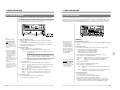
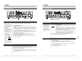
10-5 SUB TIME CODE RECORDING AND PLAYBACK
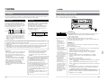
10-6 TIME CODE SWITCH SETTING FOR EDITING
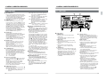
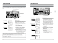
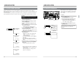
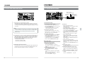
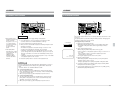
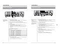
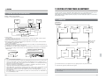
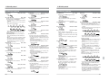
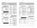
In addition to the main time code used for editing, this unit can also record (and play back) an optional sub time
code in the time code data area on the tape.
VIDEO CASSETTE RECORDER
AUDIO
INPUT
AUDIO INPUT / AUDIO MONITOR SELECT
Recording sub time code
VIDEO
INPUT
CH1
CH2
CH3
CH4
AES/EBU CH1
L
ANALOG CH1
R
CH2
CH3
CH4
LINE
CH2
CH3
CH4
CPN
SDI
AUDIO
MONITOR
BR-D95U
POWER
SIF
ON
I
OFF
O
COMPONENT DIGITAL
Variable Motion
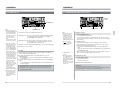
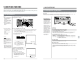
● In the sub time code sector, you can record either the same data as in the main
time code or the VITC time code received through the [VIDEO IN] connector.
TIME CDOE
DF
Notes
● When menu switch No. 450
<SUB TC<VITC> REC> is
set to “ON (1)”
The sub time code is
regenerated with the VITC
signal superimposed on the
video signal from the
[VIDEO IN] connector.
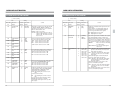
1. Select data to be recorded on the sub time code.
● Menu switch No. 450 <SUB TC (VITC) REC>
OFF (0): “00:00:00:00” is always recorded on the sub time code.
ON (1): Records the VITC received from the [VIDEO IN] connector on the
sub time code.
Initial setting: ON (1)
GND
INT
EXT
OFF
ON
CF
FREE PRESET
REC
REGEN
8
ON
OFF
4
(625) ON SCREEN
TIME CDOE
DF
INT
FREE PRESET
NDF
EXT
REC
REGEN
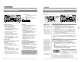
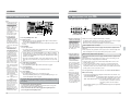
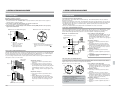
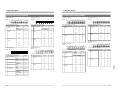
● Set the switches on the BR-D95U (recording VCR) as follows.
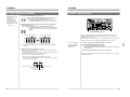
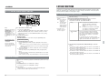
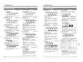
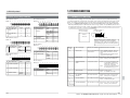
● Sub time code data is output through the [VIDEO OUT] connector as a VITC time
code signal superimposed on the video signal.
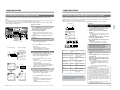
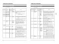
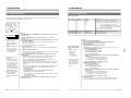
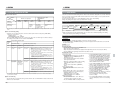
1. Enable sub time code playback.
● Set menu switch No. 451 <VITC OUTSEL> to “SUB TC (0)”.
Factory setting: TC (1)
No sub time code data is
output through the rear
panel [TC OUT] connector.
Only main time code (LTC)
is output from the built-in
time code reader.
HID
Front sub panel
2. Record the sub time code.
Press the [PLAY] button while pressing the [REC] button.
The selected time code will be recorded.
Play back the sub time code.
● [TC OUT] connector output
NDF
RF
SERVICE USE ONLY
Note
If there is no external sync
signal generator available,
send a video input signal to
the [VIDEO REF IN] connector
on the recording VCR.
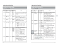
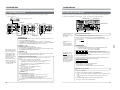
Front panel switch setting
● [INT/EXT] switch: Set to “INT”.
● [REC/FREE] switch: Set to “FREE”.
● [PRESET/REGEN] switch: Set to “PRESET”.
● Set the menu switches as required.
2. Play back the sub time code.
Press the [PLAY] button.
[ Sub time code data is output through the [VIDEO OUT] connector as a VITC
time code signal superimposed on the video signal.
Sub time code data (indicated with SUB) is shown with the main time code
on the on-screen display (with menu switch No. 504 <INFORMATION
SELECT> set to “TIME+SUB TC (3)” or “TIME+SUB TC+MODE (4)”).
● When menu switch No. 457 <UB PRESET AUTO> is set to “ON (1)”, the user
bit data stored in memory is recorded.
● Send an external sync signal to the [VIDEO REF IN]
connector for editing.
Deliver a black burst or a standard color signal as an external sync signal.
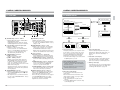
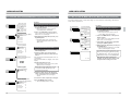
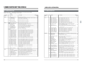
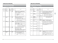
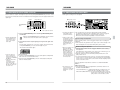
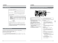
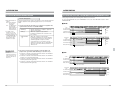
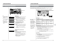
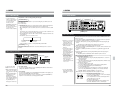
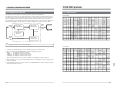
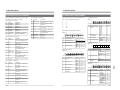
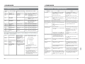
Time Code Signal Flow
Time code data flow depends on the setting of the menu switch or the [INT/EXT]
switch.
Use this as a reference for switch setting.
INT/EXT switch
Internal time code
generator
Recording area
INT
Recording
system
Main time
code domain
TC OUT
Playback system
EXT
TC IN
LTC
TC
LINE OUT
OFF
00:00:00:00
VITC
Sub time
code domain
Menu switch No.409
VIDEO IN
<EXT REGEN TC>
(LINE /
COMPONENT/
SERIAL V/A)
102
ON
SUB TC
Menu switch No.451
<VITC OUT SELECT>
Menu switch No.450
<SUB TC (VITC) REC>
103