1
MELSEC iQ-R CC-Link IE Controller Network
User's Manual
(Application)
-RJ71GP21-SX
SAFETY PRECAUTIONS
(Read these precautions before using this product.)
Before using this product, please read this manual and the relevant manuals carefully and pay full attention to safety to handle
the product correctly.
The precautions given in this manual are concerned with this product only. For the safety precautions of the programmable
controller system, refer to the user's manual for the CPU module used.
In this manual, the safety precautions are classified into two levels: "
WARNING" and "
CAUTION".
WARNING
Indicates that incorrect handling may cause hazardous conditions, resulting in
death or severe injury.
CAUTION
Indicates that incorrect handling may cause hazardous conditions, resulting in
minor or moderate injury or property damage.
Under some circumstances, failure to observe the precautions given under "
CAUTION" may lead to serious
consequences.
Observe the precautions of both levels because they are important for personal and system safety.
Make sure that the end users read this manual and then keep the manual in a safe place for future reference.
1
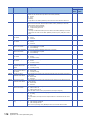
[Design Precautions]
WARNING
● Configure safety circuits external to the programmable controller to ensure that the entire system
operates safely even when a fault occurs in the external power supply or the programmable controller.
Failure to do so may result in an accident due to an incorrect output or malfunction.
(1) Emergency stop circuits, protection circuits, and protective interlock circuits for conflicting
operations (such as forward/reverse rotations or upper/lower limit positioning) must be configured
external to the programmable controller.
(2) When the programmable controller detects an abnormal condition, it stops the operation and all
outputs are:
• Turned off if the overcurrent or overvoltage protection of the power supply module is activated.
• Held or turned off according to the parameter setting if the self-diagnostic function of the CPU
module detects an error such as a watchdog timer error.
(3) All outputs may be turned on if an error occurs in a part, such as an I/O control part, where the
CPU module cannot detect any error. To ensure safety operation in such a case, provide a safety
mechanism or a fail-safe circuit external to the programmable controller. For a fail-safe circuit
example, refer to "General Safety Requirements" in the MELSEC iQ-R Module Configuration
Manual.
(4) Outputs may remain on or off due to a failure of a component such as a relay and transistor in an
output circuit. Configure an external circuit for monitoring output signals that could cause a
serious accident.
● In an output circuit, when a load current exceeding the rated current or an overcurrent caused by a
load short-circuit flows for a long time, it may cause smoke and fire. To prevent this, configure an
external safety circuit, such as a fuse.
● Configure a circuit so that the programmable controller is turned on first and then the external power
supply. If the external power supply is turned on first, an accident may occur due to an incorrect output
or malfunction.
● For the operating status of each station after a communication failure, refer to manuals relevant to the
network. Incorrect output or malfunction due to a communication failure may result in an accident.
● When connecting an external device with a CPU module or intelligent function module to modify data
of a running programmable controller, configure an interlock circuit in the program to ensure that the
entire system will always operate safely. For other forms of control (such as program modification,
parameter change, forced output, or operating status change) of a running programmable controller,
read the relevant manuals carefully and ensure that the operation is safe before proceeding. Improper
operation may damage machines or cause accidents.
2
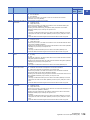
[Design Precautions]
WARNING
● Especially, when a remote programmable controller is controlled by an external device, immediate
action cannot be taken if a problem occurs in the programmable controller due to a communication
failure. To prevent this, configure an interlock circuit in the program, and determine corrective actions
to be taken between the external device and CPU module in case of a communication failure.
● Do not write any data to the "system area" and "write-protect area" of the buffer memory in the
module. Also, do not use any "use prohibited" signals as an output signal from the CPU module to the
intelligent function module. Doing so may cause malfunction of the programmable controller system.
For the "system area", "write-protect area", and the "use prohibited" signals, refer to the user's manual
for the module used.
● If a communication cable is disconnected, the network may be unstable, resulting in a communication
failure of multiple stations. Configure an interlock circuit in the program to ensure that the entire
system will always operate safely even if communications fail. Failure to do so may result in an
accident due to an incorrect output or malfunction.
● To maintain the safety of the programmable controller system against unauthorized access from
external devices via the network, take appropriate measures. To maintain the safety against
unauthorized access via the Internet, take measures such as installing a firewall.
● The optical transmitter and receiver of the CC-Link IE Controller Network module use laser diodes
(class 1 in accordance with IEC 60825-1). Do not look directly at a laser beam. Doing so may harm
your eyes.
[Design Precautions]
CAUTION
● Do not install the control lines or communication cables together with the main circuit lines or power
cables. Keep a distance of 100mm or more between them. Failure to do so may result in malfunction
due to noise.
● During control of an inductive load such as a lamp, heater, or solenoid valve, a large current
(approximately ten times greater than normal) may flow when the output is turned from off to on.
Therefore, use a module that has a sufficient current rating.
● After the CPU module is powered on or is reset, the time taken to enter the RUN status varies
depending on the system configuration, parameter settings, and/or program size. Design circuits so
that the entire system will always operate safely, regardless of the time.
● Do not power off the programmable controller or reset the CPU module while the settings are being
written. Doing so will make the data in the flash ROM undefined. The values need to be set in the
buffer memory and written to the flash ROM again. Doing so also may cause malfunction or failure of
the module.
● Reset the CPU module after changing the parameters. Failure to do so may cause malfunction
because the previous parameter settings remain in the module.
● When changing the operating status of the CPU module from external devices (such as the remote
RUN/STOP functions), select "Do Not OPEN in Program" for "Open Method Setting" in the module
parameters. If "OPEN in Program" is selected, an execution of the remote STOP function causes the
communication line to close. Consequently, the CPU module cannot reopen the line, and external
devices cannot execute the remote RUN function.
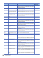
3
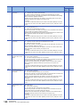
[Installation Precautions]
WARNING
● Shut off the external power supply (all phases) used in the system before mounting or removing the
module. Failure to do so may result in electric shock or cause the module to fail or malfunction.
[Installation Precautions]
CAUTION
● Use the programmable controller in an environment that meets the general specifications in the Safety
Guidelines included with the base unit. Failure to do so may result in electric shock, fire, malfunction,
or damage to or deterioration of the product.
● To mount a module, place the concave part(s) located at the bottom onto the guide(s) of the base unit,
and push in the module until the hook(s) located at the top snaps into place. Incorrect interconnection
may cause malfunction, failure, or drop of the module.
● When using the programmable controller in an environment of frequent vibrations, fix the module with
a screw.
● Tighten the screws within the specified torque range. Undertightening can cause drop of the screw,
short circuit, or malfunction. Overtightening can damage the screw and/or module, resulting in drop,
short circuit, or malfunction.
● When using an extension cable, connect it to the extension cable connector of the base unit securely.
Check the connection for looseness. Poor contact may cause malfunction.
● When using an SD memory card, fully insert it into the SD memory card slot. Check that it is inserted
completely. Poor contact may cause malfunction.
● Securely insert an extended SRAM cassette into the cassette connector of the CPU module. After
insertion, close the cassette cover and check that the cassette is inserted completely. Poor contact
may cause malfunction.
● Do not directly touch any conductive parts and electronic components of the module, SD memory
card, extended SRAM cassette, or connector. Doing so can cause malfunction or failure of the
module.
[Wiring Precautions]
WARNING
● Shut off the external power supply (all phases) used in the system before installation and wiring.
Failure to do so may result in electric shock or cause the module to fail or malfunction.
● After installation and wiring, attach the included terminal cover to the module before turning it on for
operation. Failure to do so may result in electric shock.
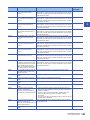
4
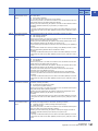
[Wiring Precautions]
CAUTION
● Individually ground the FG and LG terminals of the programmable controller with a ground resistance
of 100 ohms or less. Failure to do so may result in electric shock or malfunction.
● Use applicable solderless terminals and tighten them within the specified torque range. If any spade
solderless terminal is used, it may be disconnected when the terminal screw comes loose, resulting in
failure.
● Check the rated voltage and signal layout before wiring to the module, and connect the cables
correctly. Connecting a power supply with a different voltage rating or incorrect wiring may cause fire
or failure.
● Connectors for external devices must be crimped or pressed with the tool specified by the
manufacturer, or must be correctly soldered. Incomplete connections may cause short circuit, fire, or
malfunction.
● Securely connect the connector to the module. Poor contact may cause malfunction.
● Do not install the control lines or communication cables together with the main circuit lines or power
cables. Keep a distance of 100mm or more between them. Failure to do so may result in malfunction
due to noise.
● Place the cables in a duct or clamp them. If not, dangling cable may swing or inadvertently be pulled,
resulting in damage to the module or cables or malfunction due to poor contact. Do not clamp the
extension cables with the jacket stripped.
● Check the interface type and correctly connect the cable. Incorrect wiring (connecting the cable to an
incorrect interface) may cause failure of the module and external device.
● Tighten the terminal screws or connector screws within the specified torque range. Undertightening
can cause drop of the screw, short circuit, fire, or malfunction. Overtightening can damage the screw
and/or module, resulting in drop, short circuit, fire, or malfunction.
● When disconnecting the cable from the module, do not pull the cable by the cable part. For the cable
with connector, hold the connector part of the cable. For the cable connected to the terminal block,
loosen the terminal screw. Pulling the cable connected to the module may result in malfunction or
damage to the module or cable.
● Prevent foreign matter such as dust or wire chips from entering the module. Such foreign matter can
cause a fire, failure, or malfunction.
● A protective film is attached to the top of the module to prevent foreign matter, such as wire chips,
from entering the module during wiring. Do not remove the film during wiring. Remove it for heat
dissipation before system operation.
● Programmable controllers must be installed in control panels. Connect the main power supply to the
power supply module in the control panel through a relay terminal block. Wiring and replacement of a
power supply module must be performed by qualified maintenance personnel with knowledge of
protection against electric shock. For wiring, refer to the MELSEC iQ-R Module Configuration Manual.
● For Ethernet cables to be used in the system, select the ones that meet the specifications in the
MELSEC iQ-R Ethernet/CC-Link IE User's Manual (Startup). If not, normal data transmission is not
guaranteed.
● For optical fiber cables to be used in the system, select the ones that meet the specifications in the
MELSEC iQ-R Ethernet/CC-Link IE User's Manual (Startup). If not, normal data transmission is not
guaranteed.
5
[Startup and Maintenance Precautions]
WARNING
● Do not touch any terminal while power is on. Doing so will cause electric shock or malfunction.
● Correctly connect the battery connector. Do not charge, disassemble, heat, short-circuit, solder, or
throw the battery into the fire. Also, do not expose it to liquid or strong shock. Doing so will cause the
battery to produce heat, explode, ignite, or leak, resulting in injury and fire.
● Shut off the external power supply (all phases) used in the system before cleaning the module or
retightening the terminal screws, connector screws, or module fixing screws. Failure to do so may
result in electric shock.
[Startup and Maintenance Precautions]
CAUTION
● When connecting an external device with a CPU module or intelligent function module to modify data
of a running programmable controller, configure an interlock circuit in the program to ensure that the
entire system will always operate safely. For other forms of control (such as program modification,
parameter change, forced output, or operating status change) of a running programmable controller,
read the relevant manuals carefully and ensure that the operation is safe before proceeding. Improper
operation may damage machines or cause accidents.
● Especially, when a remote programmable controller is controlled by an external device, immediate
action cannot be taken if a problem occurs in the programmable controller due to a communication
failure. To prevent this, configure an interlock circuit in the program, and determine corrective actions
to be taken between the external device and CPU module in case of a communication failure.
● Do not disassemble or modify the modules. Doing so may cause failure, malfunction, injury, or a fire.
● Use any radio communication device such as a cellular phone or PHS (Personal Handy-phone
System) more than 25cm away in all directions from the programmable controller. Failure to do so
may cause malfunction.
● Shut off the external power supply (all phases) used in the system before mounting or removing the
module. Failure to do so may cause the module to fail or malfunction.
● Tighten the screws within the specified torque range. Undertightening can cause drop of the
component or wire, short circuit, or malfunction. Overtightening can damage the screw and/or module,
resulting in drop, short circuit, or malfunction.
● After the first use of the product, do not mount/remove the module to/from the base unit, and the
terminal block to/from the module, and do not insert/remove the extended SRAM cassette to/from the
CPU module more than 50 times (IEC 61131-2 compliant) respectively. Exceeding the limit may cause
malfunction.
● After the first use of the product, do not insert/remove the SD memory card to/from the CPU module
more than 500 times. Exceeding the limit may cause malfunction.
● Do not touch the metal terminals on the back side of the SD memory card. Doing so may cause
malfunction or failure.
● Do not touch the integrated circuits on the circuit board of an extended SRAM cassette. Doing so may
cause malfunction or failure.
● Do not drop or apply shock to the battery to be installed in the module. Doing so may damage the
battery, causing the battery fluid to leak inside the battery. If the battery is dropped or any shock is
applied to it, dispose of it without using.
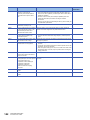
6
[Startup and Maintenance Precautions]
CAUTION
● Startup and maintenance of a control panel must be performed by qualified maintenance personnel
with knowledge of protection against electric shock. Lock the control panel so that only qualified
maintenance personnel can operate it.
● Before handling the module, touch a conducting object such as a grounded metal to discharge the
static electricity from the human body. Failure to do so may cause the module to fail or malfunction.
[Operating Precautions]
CAUTION
● When changing data and operating status, and modifying program of the running programmable
controller from an external device such as a personal computer connected to an intelligent function
module, read relevant manuals carefully and ensure the safety before operation. Incorrect change or
modification may cause system malfunction, damage to the machines, or accidents.
● Do not power off the programmable controller or reset the CPU module while the setting values in the
buffer memory are being written to the flash ROM in the module. Doing so will make the data in the
flash ROM undefined. The values need to be set in the buffer memory and written to the flash ROM
again. Doing so also can cause malfunction or failure of the module.
[Disposal Precautions]
CAUTION
● When disposing of this product, treat it as industrial waste.
● When disposing of batteries, separate them from other wastes according to the local regulations. For
details on battery regulations in EU member states, refer to the MELSEC iQ-R Module Configuration
Manual.
[Transportation Precautions]
CAUTION
● When transporting lithium batteries, follow the transportation regulations. For details on the regulated
models, refer to the MELSEC iQ-R Module Configuration Manual.
● The halogens (such as fluorine, chlorine, bromine, and iodine), which are contained in a fumigant
used for disinfection and pest control of wood packaging materials, may cause failure of the product.
Prevent the entry of fumigant residues into the product or consider other methods (such as heat
treatment) instead of fumigation. The disinfection and pest control measures must be applied to
unprocessed raw wood.
7
CONDITIONS OF USE FOR THE PRODUCT
(1) Mitsubishi programmable controller ("the PRODUCT") shall be used in conditions;
i) where any problem, fault or failure occurring in the PRODUCT, if any, shall not lead to any major or serious accident;
and
ii) where the backup and fail-safe function are systematically or automatically provided outside of the PRODUCT for the
case of any problem, fault or failure occurring in the PRODUCT.
(2) The PRODUCT has been designed and manufactured for the purpose of being used in general industries.
MITSUBISHI SHALL HAVE NO RESPONSIBILITY OR LIABILITY (INCLUDING, BUT NOT LIMITED TO ANY AND ALL
RESPONSIBILITY OR LIABILITY BASED ON CONTRACT, WARRANTY, TORT, PRODUCT LIABILITY) FOR ANY
INJURY OR DEATH TO PERSONS OR LOSS OR DAMAGE TO PROPERTY CAUSED BY the PRODUCT THAT ARE
OPERATED OR USED IN APPLICATION NOT INTENDED OR EXCLUDED BY INSTRUCTIONS, PRECAUTIONS, OR
WARNING CONTAINED IN MITSUBISHI'S USER, INSTRUCTION AND/OR SAFETY MANUALS, TECHNICAL
BULLETINS AND GUIDELINES FOR the PRODUCT.
("Prohibited Application")
Prohibited Applications include, but not limited to, the use of the PRODUCT in;
• Nuclear Power Plants and any other power plants operated by Power companies, and/or any other cases in which the
public could be affected if any problem or fault occurs in the PRODUCT.
• Railway companies or Public service purposes, and/or any other cases in which establishment of a special quality
assurance system is required by the Purchaser or End User.
• Aircraft or Aerospace, Medical applications, Train equipment, transport equipment such as Elevator and Escalator,
Incineration and Fuel devices, Vehicles, Manned transportation, Equipment for Recreation and Amusement, and
Safety devices, handling of Nuclear or Hazardous Materials or Chemicals, Mining and Drilling, and/or other
applications where there is a significant risk of injury to the public or property.
Notwithstanding the above, restrictions Mitsubishi may in its sole discretion, authorize use of the PRODUCT in one or
more of the Prohibited Applications, provided that the usage of the PRODUCT is limited only for the specific
applications agreed to by Mitsubishi and provided further that no special quality assurance or fail-safe, redundant or
other safety features which exceed the general specifications of the PRODUCTs are required. For details, please
contact the Mitsubishi representative in your region.
INTRODUCTION
Thank you for purchasing the Mitsubishi MELSEC iQ-R series programmable controllers.
This manual describes the functions and troubleshooting of the relevant product listed below.
Before using this product, please read this manual and the relevant manuals carefully and develop familiarity with the
functions and performance of the MELSEC iQ-R series programmable controller to handle the product correctly.
When applying the program examples provided in this manual to an actual system, ensure the applicability and confirm that it
will not cause system control problems.
Please make sure that the end users read this manual.
Relevant product
RJ71GP21-SX
8
CONTENTS
SAFETY PRECAUTIONS . . . . . . . . . . . . . . . . . . . . . . . . . . . . . . . . . . . . . . . . . . . . . . . . . . . . . . . . . . . . . . . . . . . .1
CONDITIONS OF USE FOR THE PRODUCT . . . . . . . . . . . . . . . . . . . . . . . . . . . . . . . . . . . . . . . . . . . . . . . . . . . .8
INTRODUCTION . . . . . . . . . . . . . . . . . . . . . . . . . . . . . . . . . . . . . . . . . . . . . . . . . . . . . . . . . . . . . . . . . . . . . . . . . . .8
RELEVANT MANUALS . . . . . . . . . . . . . . . . . . . . . . . . . . . . . . . . . . . . . . . . . . . . . . . . . . . . . . . . . . . . . . . . . . . . . 11
CHAPTER 1
1.1
FUNCTIONS
14
Cyclic Transmission . . . . . . . . . . . . . . . . . . . . . . . . . . . . . . . . . . . . . . . . . . . . . . . . . . . . . . . . . . . . . . . . . . . . . 14
Data flow and link device assignment . . . . . . . . . . . . . . . . . . . . . . . . . . . . . . . . . . . . . . . . . . . . . . . . . . . . . . . . . 14
Link refresh . . . . . . . . . . . . . . . . . . . . . . . . . . . . . . . . . . . . . . . . . . . . . . . . . . . . . . . . . . . . . . . . . . . . . . . . . . . . . 16
Direct access to link devices . . . . . . . . . . . . . . . . . . . . . . . . . . . . . . . . . . . . . . . . . . . . . . . . . . . . . . . . . . . . . . . . 18
Cyclic data integrity assurance . . . . . . . . . . . . . . . . . . . . . . . . . . . . . . . . . . . . . . . . . . . . . . . . . . . . . . . . . . . . . . 22
Interlink transmission. . . . . . . . . . . . . . . . . . . . . . . . . . . . . . . . . . . . . . . . . . . . . . . . . . . . . . . . . . . . . . . . . . . . . . 27
CONTENTS
TERMS . . . . . . . . . . . . . . . . . . . . . . . . . . . . . . . . . . . . . . . . . . . . . . . . . . . . . . . . . . . . . . . . . . . . . . . . . . . . . . . . .12
Cyclic transmission punctuality assurance . . . . . . . . . . . . . . . . . . . . . . . . . . . . . . . . . . . . . . . . . . . . . . . . . . . . . 28
Group cyclic transmission . . . . . . . . . . . . . . . . . . . . . . . . . . . . . . . . . . . . . . . . . . . . . . . . . . . . . . . . . . . . . . . . . . 29
Number of send points extension . . . . . . . . . . . . . . . . . . . . . . . . . . . . . . . . . . . . . . . . . . . . . . . . . . . . . . . . . . . . 30
Reception status when an error occurs . . . . . . . . . . . . . . . . . . . . . . . . . . . . . . . . . . . . . . . . . . . . . . . . . . . . . . . . 33
Cyclic transmission stop and restart . . . . . . . . . . . . . . . . . . . . . . . . . . . . . . . . . . . . . . . . . . . . . . . . . . . . . . . . . . 33
1.2
Transient Transmission . . . . . . . . . . . . . . . . . . . . . . . . . . . . . . . . . . . . . . . . . . . . . . . . . . . . . . . . . . . . . . . . . . 34
Communications within the same network . . . . . . . . . . . . . . . . . . . . . . . . . . . . . . . . . . . . . . . . . . . . . . . . . . . . . 34
Communications with different networks . . . . . . . . . . . . . . . . . . . . . . . . . . . . . . . . . . . . . . . . . . . . . . . . . . . . . . . 35
1.3
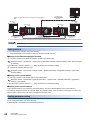
IP Packet Transfer Function . . . . . . . . . . . . . . . . . . . . . . . . . . . . . . . . . . . . . . . . . . . . . . . . . . . . . . . . . . . . . . . 37
System configuration . . . . . . . . . . . . . . . . . . . . . . . . . . . . . . . . . . . . . . . . . . . . . . . . . . . . . . . . . . . . . . . . . . . . . . 38
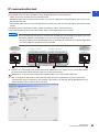
Setting . . . . . . . . . . . . . . . . . . . . . . . . . . . . . . . . . . . . . . . . . . . . . . . . . . . . . . . . . . . . . . . . . . . . . . . . . . . . . . . . . 38
IP communication test . . . . . . . . . . . . . . . . . . . . . . . . . . . . . . . . . . . . . . . . . . . . . . . . . . . . . . . . . . . . . . . . . . . . . 41
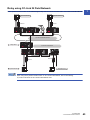
Relay using CC-Link IE Field Network . . . . . . . . . . . . . . . . . . . . . . . . . . . . . . . . . . . . . . . . . . . . . . . . . . . . . . . . 43
Precautions . . . . . . . . . . . . . . . . . . . . . . . . . . . . . . . . . . . . . . . . . . . . . . . . . . . . . . . . . . . . . . . . . . . . . . . . . . . . . 44
Example of communications using the IP packet transfer function . . . . . . . . . . . . . . . . . . . . . . . . . . . . . . . . . . . 46
Communication speed. . . . . . . . . . . . . . . . . . . . . . . . . . . . . . . . . . . . . . . . . . . . . . . . . . . . . . . . . . . . . . . . . . . . . 48
1.4
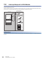
Interrupt Request to CPU Module . . . . . . . . . . . . . . . . . . . . . . . . . . . . . . . . . . . . . . . . . . . . . . . . . . . . . . . . . . 50
1.5
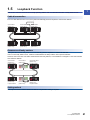
Loopback Function . . . . . . . . . . . . . . . . . . . . . . . . . . . . . . . . . . . . . . . . . . . . . . . . . . . . . . . . . . . . . . . . . . . . . . 51
CHAPTER 2
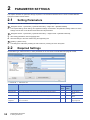
PARAMETER SETTINGS
52
2.1
Setting Parameters . . . . . . . . . . . . . . . . . . . . . . . . . . . . . . . . . . . . . . . . . . . . . . . . . . . . . . . . . . . . . . . . . . . . . . 52
2.2
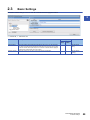
Required Settings . . . . . . . . . . . . . . . . . . . . . . . . . . . . . . . . . . . . . . . . . . . . . . . . . . . . . . . . . . . . . . . . . . . . . . . 52
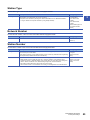
Station Type. . . . . . . . . . . . . . . . . . . . . . . . . . . . . . . . . . . . . . . . . . . . . . . . . . . . . . . . . . . . . . . . . . . . . . . . . . . . . 53
Network Number . . . . . . . . . . . . . . . . . . . . . . . . . . . . . . . . . . . . . . . . . . . . . . . . . . . . . . . . . . . . . . . . . . . . . . . . . 53
Station Number . . . . . . . . . . . . . . . . . . . . . . . . . . . . . . . . . . . . . . . . . . . . . . . . . . . . . . . . . . . . . . . . . . . . . . . . . . 53
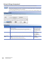
Network Range Assignment . . . . . . . . . . . . . . . . . . . . . . . . . . . . . . . . . . . . . . . . . . . . . . . . . . . . . . . . . . . . . . . . 54
2.3
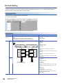
Basic Settings . . . . . . . . . . . . . . . . . . . . . . . . . . . . . . . . . . . . . . . . . . . . . . . . . . . . . . . . . . . . . . . . . . . . . . . . . . 59
Refresh Setting . . . . . . . . . . . . . . . . . . . . . . . . . . . . . . . . . . . . . . . . . . . . . . . . . . . . . . . . . . . . . . . . . . . . . . . . . . 60
Network Topology . . . . . . . . . . . . . . . . . . . . . . . . . . . . . . . . . . . . . . . . . . . . . . . . . . . . . . . . . . . . . . . . . . . . . . . . 61
2.4
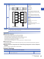
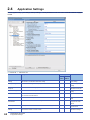
Application Settings . . . . . . . . . . . . . . . . . . . . . . . . . . . . . . . . . . . . . . . . . . . . . . . . . . . . . . . . . . . . . . . . . . . . . 62
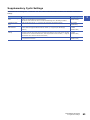
Supplementary Cyclic Settings . . . . . . . . . . . . . . . . . . . . . . . . . . . . . . . . . . . . . . . . . . . . . . . . . . . . . . . . . . . . . . 63
Interrupt Settings . . . . . . . . . . . . . . . . . . . . . . . . . . . . . . . . . . . . . . . . . . . . . . . . . . . . . . . . . . . . . . . . . . . . . . . . . 64
Transient Transmission Group No. . . . . . . . . . . . . . . . . . . . . . . . . . . . . . . . . . . . . . . . . . . . . . . . . . . . . . . . . . . . 68
Dynamic Routing . . . . . . . . . . . . . . . . . . . . . . . . . . . . . . . . . . . . . . . . . . . . . . . . . . . . . . . . . . . . . . . . . . . . . . . . . 68
IP Address . . . . . . . . . . . . . . . . . . . . . . . . . . . . . . . . . . . . . . . . . . . . . . . . . . . . . . . . . . . . . . . . . . . . . . . . . . . . . . 68
9
Parameter Name . . . . . . . . . . . . . . . . . . . . . . . . . . . . . . . . . . . . . . . . . . . . . . . . . . . . . . . . . . . . . . . . . . . . . . . . . 68
Event Reception from Other Stations . . . . . . . . . . . . . . . . . . . . . . . . . . . . . . . . . . . . . . . . . . . . . . . . . . . . . . . . . 68
Module Operation Mode . . . . . . . . . . . . . . . . . . . . . . . . . . . . . . . . . . . . . . . . . . . . . . . . . . . . . . . . . . . . . . . . . . . 69
Interlink Transmission Settings . . . . . . . . . . . . . . . . . . . . . . . . . . . . . . . . . . . . . . . . . . . . . . . . . . . . . . . . . . . . . . 70
CHAPTER 3
TROUBLESHOOTING
74
3.1
Checking with LED . . . . . . . . . . . . . . . . . . . . . . . . . . . . . . . . . . . . . . . . . . . . . . . . . . . . . . . . . . . . . . . . . . . . . . 74
3.2
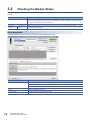
Checking the Module Status. . . . . . . . . . . . . . . . . . . . . . . . . . . . . . . . . . . . . . . . . . . . . . . . . . . . . . . . . . . . . . . 76
3.3
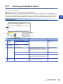
Checking the Network Status . . . . . . . . . . . . . . . . . . . . . . . . . . . . . . . . . . . . . . . . . . . . . . . . . . . . . . . . . . . . . . 79
3.4
Troubleshooting by Symptom . . . . . . . . . . . . . . . . . . . . . . . . . . . . . . . . . . . . . . . . . . . . . . . . . . . . . . . . . . . . . 89
3.5
List of Error Codes . . . . . . . . . . . . . . . . . . . . . . . . . . . . . . . . . . . . . . . . . . . . . . . . . . . . . . . . . . . . . . . . . . . . . . 93
3.6
List of Parameter Numbers. . . . . . . . . . . . . . . . . . . . . . . . . . . . . . . . . . . . . . . . . . . . . . . . . . . . . . . . . . . . . . . 103
3.7
List of Event History . . . . . . . . . . . . . . . . . . . . . . . . . . . . . . . . . . . . . . . . . . . . . . . . . . . . . . . . . . . . . . . . . . . . 104
APPENDICES
105
Appendix 1 Module Label . . . . . . . . . . . . . . . . . . . . . . . . . . . . . . . . . . . . . . . . . . . . . . . . . . . . . . . . . . . . . . . . . . . . . 105
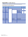
Appendix 2 Buffer Memory . . . . . . . . . . . . . . . . . . . . . . . . . . . . . . . . . . . . . . . . . . . . . . . . . . . . . . . . . . . . . . . . . . . . 106
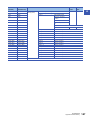
List of buffer memory addresses . . . . . . . . . . . . . . . . . . . . . . . . . . . . . . . . . . . . . . . . . . . . . . . . . . . . . . . . . . . . 106
Details of buffer memory addresses . . . . . . . . . . . . . . . . . . . . . . . . . . . . . . . . . . . . . . . . . . . . . . . . . . . . . . . . . 109
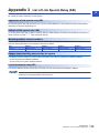
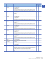
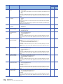
Appendix 3 List of Link Special Relay (SB) . . . . . . . . . . . . . . . . . . . . . . . . . . . . . . . . . . . . . . . . . . . . . . . . . . . . . . . 113
Appendix 4 List of Link Special Register (SW) . . . . . . . . . . . . . . . . . . . . . . . . . . . . . . . . . . . . . . . . . . . . . . . . . . . . 123
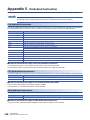
Appendix 5 Dedicated Instruction . . . . . . . . . . . . . . . . . . . . . . . . . . . . . . . . . . . . . . . . . . . . . . . . . . . . . . . . . . . . . . 140
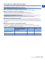
Precautions for dedicated instructions. . . . . . . . . . . . . . . . . . . . . . . . . . . . . . . . . . . . . . . . . . . . . . . . . . . . . . . . 141
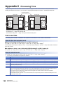
Appendix 6 Processing Time . . . . . . . . . . . . . . . . . . . . . . . . . . . . . . . . . . . . . . . . . . . . . . . . . . . . . . . . . . . . . . . . . . 142
Link scan time . . . . . . . . . . . . . . . . . . . . . . . . . . . . . . . . . . . . . . . . . . . . . . . . . . . . . . . . . . . . . . . . . . . . . . . . . . 142
Cyclic transmission delay time . . . . . . . . . . . . . . . . . . . . . . . . . . . . . . . . . . . . . . . . . . . . . . . . . . . . . . . . . . . . . 143
Interlink transmission time . . . . . . . . . . . . . . . . . . . . . . . . . . . . . . . . . . . . . . . . . . . . . . . . . . . . . . . . . . . . . . . . . 144
INDEX
146
REVISIONS . . . . . . . . . . . . . . . . . . . . . . . . . . . . . . . . . . . . . . . . . . . . . . . . . . . . . . . . . . . . . . . . . . . . . . . . . . . . .148
WARRANTY . . . . . . . . . . . . . . . . . . . . . . . . . . . . . . . . . . . . . . . . . . . . . . . . . . . . . . . . . . . . . . . . . . . . . . . . . . . .149
TRADEMARKS . . . . . . . . . . . . . . . . . . . . . . . . . . . . . . . . . . . . . . . . . . . . . . . . . . . . . . . . . . . . . . . . . . . . . . . . . .150
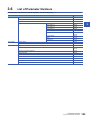
10
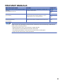
RELEVANT MANUALS
Manual name [manual number]
Description
Available form
MELSEC iQ-R CC-Link IE Controller Network User's Manual
(Application)
[SH-081258ENG] (this manual)
Functions, parameter settings, troubleshooting, and buffer memory of
CC-Link IE Controller Network
Print book
MELSEC iQ-R Ethernet/CC-Link IE User's Manual (Startup)
[SH-081256ENG]
Specifications, procedures before operation, system configuration,
wiring, and communication examples of Ethernet, CC-Link IE
Controller Network, and CC-Link IE Field Network
Print book
MELSEC iQ-R Programming Manual (Instructions, Standard
Functions/Function Blocks)
[SH-081266ENG]
Instructions for the CPU module, dedicated instructions for the
intelligent function modules, and standard functions/function blocks
e-Manual
EPUB
PDF
e-Manual
EPUB
PDF
e-Manual
EPUB
PDF
e-Manual refers to the Mitsubishi FA electronic book manuals that can be browsed using a dedicated tool.
e-Manual has the following features:
• Required information can be cross-searched in multiple manuals.
• Other manuals can be accessed from the links in the manual.
• The hardware specifications of each part can be found from the product figures.
• Pages that users often browse can be bookmarked.
11
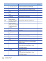
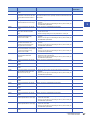
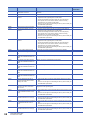
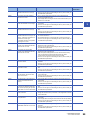
TERMS
Unless otherwise specified, this manual uses the following terms.
12
Term
Description
CC-Link IE Controller Networkequipped module
The abbreviation for the RJ71GP21-SX CC-Link IE Controller Network module
CC-Link IE Field Network-equipped
master/local module
A generic term for the RJ71GF11-T2 CC-Link IE Field Network master/local module and RJ71EN71 (when the CC-Link
IE Field Network function is used)
CPU module
A generic term for the MELSEC iQ-R series CPU module
Ethernet-equipped module
A generic term for the RJ71EN71 (when the Ethernet function is used) and MELSEC iQ-R series CPU module (when the
Ethernet function is used)
Ethernet device
A generic term for the devices supporting IP communication (such as personal computers)
I/O master station
A station that controls communications by the link devices (LX, LY). Up to two I/O master stations can be set for one
network (block 1 and block 2), regardless of the status of control or normal station.
MELSECNET/10
The abbreviation for the MELSECNET/10 network system
MELSECNET/H
The abbreviation for the MELSECNET/H network system
RAS
The abbreviation for Reliability, Availability, and Serviceability. This term refers to usability of automated equipment.
READ
A generic term for the JP.READ and GP.READ
RECV
A generic term for the JP.RECV and GP.RECV
RECVS
A generic term for the G.RECVS and Z.RECVS
REQ
A generic term for the J.REQ, JP.REQ, G.REQ, and GP.REQ
RIRD
A generic term for the J.RIRD, JP.RIRD, G.RIRD, and GP.RIRD
RIWT
A generic term for the J.RIWT, JP.RIWT, G.RIWT, and GP.RIWT
RRUN
A generic term for the J.RRUN, JP.RRUN, G.RRUN, GP.RRUN, Z.RRUN, and ZP.RRUN
RSTOP
A generic term for the J.RSTOP, JP.RSTOP, G.RSTOP, GP.RSTOP, Z.RSTOP, and ZP.RSTOP
RTMRD
A generic term for the J.RTMRD, JP.RTMRD, G.RTMRD, GP.RTMRD, Z.RTMRD, and ZP.RTMRD
RTMWR
A generic term for the J.RTMWR, JP.RTMWR, G.RTMWR, GP.RTMWR, Z.RTMWR, and ZP.RTMWR
SEND
A generic term for the JP.SEND and GP.SEND
SREAD
A generic term for the JP.SREAD and GP.SREAD
SWRITE
A generic term for the JP.SWRITE and GP.SWRITE
UINI
A generic term for the G.UINI, GP.UINI, Z.UINI, and ZP.UINI
WRITE
A generic term for the JP.WRITE and GP.WRITE
ZNRD
A generic term for the J.ZNRD and JP.ZNRD
ZNWR
A generic term for the J.ZNWR and JP.ZNWR
Intelligent function module
A module that has functions other than input and output, such as an A/D converter module and D/A converter module
Engineering tool
Another term for the software package for the MELSEC programmable controllers
Disconnection
A process of stopping data link if a data link error occurs
Control CPU
A CPU module that controls connected I/O modules and intelligent function modules.
In a multiple CPU system, there are multiple CPU modules and each connected module can be controlled by a different
CPU module.
Control station
A station that controls the entire network. This station can perform cyclic transmission and transient transmission with all
stations. Only one master station can be used in a network.
Shared group number
Number that is assigned to a station to allow it to share cyclic data with any given stations. Cyclic data can be shared
only with stations of the same group.
Global label
A label that is enabled for all program data when creating multiple program data in the project.
There are two types of global labels: module label that is automatically generated by GX Works3 and label that can be
created for the any of the specified devices.
Cyclic transmission
A function by which data are periodically exchanged among stations on the network using link devices
Seamless communication
Communication that allows users to access a different kind of networks without having to consider the differences as if
data were exchanged within one single network
Dedicated instruction
An instruction for using functions of the module
Relay station
A station that includes two or more network modules. Transient transmission is performed through this station to stations
on other networks
Normal station
A station that performs cyclic transmission and transient transmission with the control station and other normal stations
Data link
A generic term for cyclic transmission and transient transmission
Device
A device (X, Y, M, D, or others) in a CPU module
Term
Description
Transient transmission
A function to read/write data of a programmable controller on another station by using the dedicated instruction and test
or monitor another station by using the engineering tool
Transient transmission group
number
Number that is assigned for transient transmission to any given stations. By specifying a group of stations as transient
transmission target, data can be sent to the stations of the same group number.
I/O module
A generic term for the input module, output module, I/O combined module, and interrupt module
Network module
A generic term for the following modules:
• Ethernet interface module
• CC-Link IE Controller Network module
• Module on CC-Link IE Field Network
• MELSECNET/H module
• MELSECNET/10 module
Buffer memory
A memory in an intelligent function module, where data (such as setting values and monitoring values) exchanged with
a CPU module are stored
Baton pass
A token to send data over a network
Return
A process of restarting data link when a station recovers from an error
Module label
A label that represents one of memory areas (I/O signals and buffer memory areas) specific to each module in a given
character string.
For the module used, GX Works3 automatically generates this label, which can be used as a global label.
Reserved station
A station reserved for future use. This station is not actually connected, but counted as a connected station.
Label
A label that represents a device in a given character string
Link output (LY)
Information output from the I/O master station to a station in the block
Link scan (link scan time)
Time required for all the stations on the network to transmit data. The link scan time depends on data volume and the
number of transient transmission requests.
Link device
A device (LB, LW, LX, LY, SB, or SW) in a module on CC-Link IE Controller Network-equipped module
Link special relay (SB)
Bit data that indicates the operating status and data link status of the CC-Link IE Controller Network-equipped module
Link special register (SW)
Word data that indicates the operating status and data link status of the CC-Link IE Controller Network-equipped module
Link input (LX)
Information input from a station in the block to the I/O master station
Link refresh
Automatic data transfer between a link device (LB, LW, LX, LY, SB, or SW) of the CC-Link IE Controller Networkequipped module and a device in a CPU module, or a link device (SB or SW) of the CC-Link IE Controller Networkequipped module and a module label in a CPU module
Link refresh is performed in the END processing of the CPU module's sequence scan.
Link relay (LB)
Bit data send from each station of the network
Link register (LW)
Word data send from each station of the network
Routing
A process of selecting paths for communication with other networks.
There are two types of routing: dynamic routing that auto-selects the communication routes, and static routing where
communication routes are arbitrarily set.
13
1
FUNCTIONS
1.1
Cyclic Transmission
This function allows data to be periodically exchanged among stations on the same network using link devices.
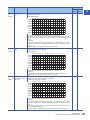
Data flow and link device assignment
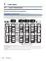
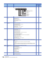
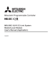
Communications using LB and LW
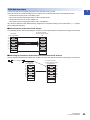
This function allows each station to write data to its own send range of a link device (LB, LW) to send them to all other stations
on the network. The status data of the link devices (LB, LW) of the control station are stored in the link devices (LB, LW) of
each normal station. The status data of the link devices (LB, LW) of normal stations are stored in the link devices (LB, LW) of
the control station and the link devices (LB, LW) of other normal stations.
B
Ò
Station No.1
Station No.4
Normal station
Normal station
CPU module
LB
LB
LB
Device or
global label
Station No.1
Station No.1
Station No.1
Station No.2
Range of
the station No.2
sending data
Station No.2
Station No.2
Station No.3
Station No.3
Range of
the station No.3
sending data
Station No.3
Station No.4
Station No.4
Station No.4
Range of
the station No.4
sending data
LW
LW
LW
Station No.1
Station No.1
Station No.1
Station No.2
Range of
the station No.2
sending data
Station No.2
Station No.2
Station No.3
Station No.3
Range of
the station No.3
sending data
Station No.3
Station No.4
Station No.4
Station No.4
Range of
the station No.4
sending data
LB
Ô
EN
D
Range of
the station No.1
sending data
Õ
Sequence
scan
EN
D
Control station
Device or
global label
Sequence
scan
Station No.3
Normal station
CPU module
Ó
Station No.2
Link
scan
Link
scan
Device or
global label
Ó
Range of
the station No.1
sending data
Ô
EN
D
Sequence
scan
LW
Device or
global label
Õ
Sequence
scan
EN
D
Send request
B
Area where data is sent to other stations
The device of the CPU module on sending side turns on.
The status data of the device of the CPU module on sending side are stored in the link devices (LB, LW) of the CC-Link IE Controller Network-equipped
module by link refresh.
The status data of the link devices (LB, LW) are stored in the link devices (LB, LW) of the receiving-side CC-Link IE Controller Network-equipped module by
link refresh.
The status data of the link devices (LB, LW) are stored in the devices of the CPU module on receiving side.
14
1 FUNCTIONS
1.1 Cyclic Transmission
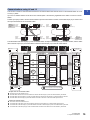
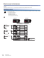
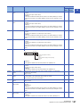
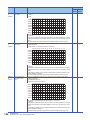
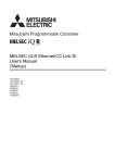
Communications using LX and LY
1
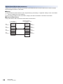
This function is used for communication between the I/O master station that controls LX and LY and another station on a oneto-one (1:1) basis.
Up to two I/O master stations can be set for one network (block 1 and block 2), regardless of the status of control or normal
station.
The link input (LX) is used to receive the information input from each station in a block, and the link output (LY) is used to send
the output information of the I/O master station.
Block 1
Control
station
(station No.1)
I/O master
station
Normal
station
(station No.2)
LX
LY
Control
station
(station No.1)
Normal
station
(station No.2)
LX
LY
LX
LY
LY
Normal
station
(station No.4)
Normal
station
(station No.3)
LX
LX
Normal
station
(station No.4)
Normal
station
(station No.3)
LY
Block 2
I/O master
station
The status data of the link output (LY) of the I/O master station is output to the link input (LX) of another station, and the status
data of the link output (LY) of another station is stored in the link input (LX) of the I/O master station.
Output instruction
X
Ö
CPU module
Device or
global label
Station No.1
Station No.2
Station No.3
Station No.4
I/O master
station
Another station
Another station
Another station
LX
LY
Station No.2
Ø
Y
CPU module
Device or
global label
Station No.2
LY
EN
D
Station No.3
Link refresh
Station No.4
Device or
global label
LY
Station No.2
×
Ø
Station No.3
Ô
Sequence
scan
Link refresh
Ø
Link
scan
LY
EN
D
Ù
Sequence
scan
Station No.4
Device or
global label
LX
Station No.2
LX
Station No.3
Link refresh
Station No.4
Ô
Ô
Õ
Station No.3
LX
Link refresh
Station No.4
X
Output instruction
Y
Sequence
scan
EN
D
EN
D
Sequence
scan
Ó
Ò
Area where data is sent to other stations
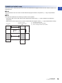
• Output from the I/O master station
The device of the CPU module turns on.
The status data of the device of the CPU module are stored in the link output (LY) of the I/O master station by link refresh.
The status data of the link output (LY) of the I/O master station are stored in the link input (LX) of another station by link scan.
The status data of the link input (LX) of another station are stored in the device of the CPU module by link refresh.
• Input from another station
The device of the CPU module turns on.
The status data of the device of the CPU module are stored in the link output (LY) of another station by link refresh.
The status data of the link output (LY) of another station are stored in the link input (LX) of the I/O master station by link scan.
The status data of the link input (LX) of the I/O master station are stored in the device of the CPU module by link refresh.
1 FUNCTIONS
1.1 Cyclic Transmission
15
Setting method
Assign the link devices under "Network Range Assignment" in "Required Settings". ( Page 54 Network Range
Assignment)
The link refresh is assigned under "Refresh Setting" in "Basic Settings". ( Page 60 Refresh Setting)
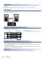
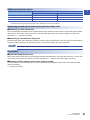
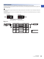
Link refresh
This function automatically transfers data between the link devices of the CC-Link IE Controller Network-equipped module
and the devices of the CPU module.
CC-Link IE Controller
Network-equipped module
CPU module
Device or
global label
Link device
LB
Link refresh
LW
LX
LY
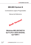
Concept of the link refresh range (number of points)
The area range set under "Refresh Setting" in "Basic Settings" and also specified under "Network Range Assignment" in
"Required Settings" is executed by link refresh.
CPU module
Device or global label
(2)
(1)
CC-Link IE Controller
Network-equipped module
Link device
Range set under "Refresh Setting" in "Basic Settings"
(2)
Actual link refresh range
(3)
Range set under "Network Range Assignment" in "Required Settings"
(3)
Link refresh
Empty
Link refresh
(1)
Empty
Link refresh
Shortening the link refresh time and transmission delay time
The link refresh time and transmission delay time can be shortened by reducing the number of link refresh points to the CPU
module. The following methods can be used to reduce the number of the link refresh points.
• In "Refresh Setting" under "Basic Settings", set only the link devices used in the CPU module as the link refresh range.
( Page 60 Refresh Setting)
• Directly access infrequently used link devices from the program, and remove the corresponding settings from the link
refresh range. ( Page 18 Direct access to link devices)
Setting method
Assign the link refresh under "Refresh Setting" in "Basic Settings". ( Page 60 Refresh Setting)
16
1 FUNCTIONS
1.1 Cyclic Transmission
Precautions
1
■Latched devices of the CPU module
If data in latched devices of the CPU module are cleared to zero on a program when the CPU module is turned off and on or
reset, the data may be output without being cleared to zero, depending on the timing of the link scan and link refresh. Execute
the actions listed in the table below not to output the data in the latched devices of the CPU module.
CPU module device
How to disable the setting
Latch relay (L), file register (R, ZR)
Use the initial device value of the CPU module to clear the device to zero.*1
CPU module device within the latch range
Delete all the latch range settings specified in "Latch Interval Operation
Setting" under "Device Latch Interval Setting" in "Memory/Device Setting" of
the CPU parameters.
*1
For the initial device value setting of the CPU module, refer to the following.
GX Works3 Operating Manual
1 FUNCTIONS
1.1 Cyclic Transmission
17
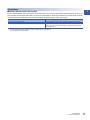
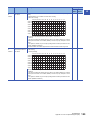
Direct access to link devices
This function allows direct access to the link devices of the CC-Link IE Controller Network-equipped module from the
program.
Specify a link device (LB, LW, LX, LY, SB, SW) as the link direct device (J\) for direct access.
Specification method
Specify the network number and the link device of the CC-Link IE Controller Network-equipped module for reading or writing.
\
J
(1)
Network number: 1 to 239
(2)
Link relay (LB): B0 to B7FFF
Link register (LW): W0 to W1FFFF
Link input (LX): X0 to X1FFF
Link output (LY): Y0 to Y1FFF
Link special relay (SB): SB0 to SB1FF
Link special register (SW): SW0 to SW1FF
(1) (2)
Ex.
Control station
(station No.1)
Normal station
(station No.2)
Network No.1
CC-Link IE Controller
Network-equipped module
Send request
CC-Link IE Controller
Network-equipped module
CPU module
LB0
J1\B0
LB0
Station No.1
Station No.1
J1\B100
LB100
LB100
Station No.2
Station No.2
Send request
LW100
MOV K20 J1\W100
LW100
Station No.1
Station No.1
LW200
= J1\W200 K300
LW200
Station No.2
Station No.2
LX
LX
Output instruction
J1\Y1000
J1\X1100
X
Y
Actual I/O
LY
1000
LY
1000
Cyclic transmission
11FF
18
1 FUNCTIONS
1.1 Cyclic Transmission
11FF
Link refresh
Readable and writable range
1
Data can be read or written between the CC-Link IE Controller Network-equipped module and CPU module mounted on the
same base unit.
■Read
All the link devices of the CC-Link IE Controller Network-equipped module can be specified. ( Page 18 Specification
method)
■Write
The range that satisfies all of the following conditions can be specified.
• Area where data is sent to other stations and outside the link refresh range ( Page 14 Data flow and link device
assignment)
• Within the link device range of the CC-Link IE Controller Network-equipped module ( Page 18 Specification method)
CC-Link IE Controller
Network-equipped module
LB
CPU module
B
(1)
Out of the link refresh range
(2)
Area where data is sent to other stations
(3)
Area for receiving the data from other stations
Link refresh
(2)
This area is
writable.
Link refresh
(1)
(3)
1 FUNCTIONS
1.1 Cyclic Transmission
19
When writing data to the area in the link refresh range, directly access the link device and write the same data
in the device of the CPU module.
• Bad example (Only direct access to the link refresh target)
Link refresh overwrites the value.
CC-Link IE Controller
Network-equipped module
CPU module
MOV K20 J1\W100
W
W100
300
LW
Link refresh
20
300
LW100
• Good example (In addition to direct access, writing the same data to the device of the CPU module)
The value written by direct access is reflected.
CC-Link IE Controller
Network-equipped module
CPU module
MOV K20 J1\W100
W
LW
MOV K20 W100
W100
20
1 FUNCTIONS
1.1 Cyclic Transmission
20
Link refresh
20
LW100
Differences from link refresh
Item
1
Access method
Link refresh
Direct access
Number of steps
1 step
2 steps
Processing speed*1
High speed
Low speed
Cyclic data integrity assurance
Available
Not available
*1
For actual values, refer to the following.
MELSEC iQ-R Programming Manual (Instructions, Standard Functions/Function Blocks)
Shortening the link refresh time and transmission delay time
■Shortening the link refresh time
Remove infrequently used link devices from the link refresh range, and directly read or write the corresponding data using link
direct devices. This function reduces the number of the link refresh points to the CPU module, resulting in a shorter link
refresh time. ( Page 16 Link refresh)
■Shortening the transmission delay time
Because the link direct device allows direct reading or writing of data to the link devices of the CC-Link IE Controller Networkequipped module at the time of the instruction execution, the transmission delay time can be shortened.
Link refresh is executed in END processing of the sequence scan of the CPU module.
Precautions
■Cyclic data integrity assurance
Direct access to link devices does not provide station-based block data assurance. Use 32-bit data assurance, or if cyclic data
of more than 32 bits needs to be assured, use interlock programs. ( Page 22 Cyclic data integrity assurance)
■Mounting multiple modules of the same network number
For the precautions on mounting multiple CC-Link IE Controller Network-equipped modules of the same network number,
refer to the following.
Page 32 Precautions
1 FUNCTIONS
1.1 Cyclic Transmission
21
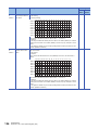
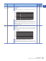
Cyclic data integrity assurance
This function assures the cyclic data integrity in units of 32 bits or station-based units.
The following three methods are available for cyclic data integrity assurance.
: Assured, : Not assured
Method
Description
Link refresh
Direct access to
link devices
Assures data in units of 32 bits. Data is automatically
assured by satisfying the assignment conditions of link
devices.
Station-based block data
assurance
Assures data in station-based units. Data is assured
by enabling the station-based block data assurance in
the parameter setting.
Interlock program
Assures data of more than 32 bits. Data is assured by
performing interlocks on programs.
32-bit data assurance
Assurance of data
of more than 32
bits
Availability
Link scans are performed asynchronously with link refresh.
Therefore, when the following cyclic data of 32 bits or more are handled, new and old data may be mixed in
units of 16 bits depending on the link refresh timing.
• Floating-point data
• Present value or command speed value of a positioning module
Sequence scan
0
END
Link refresh
Link scan
22
1 FUNCTIONS
1.1 Cyclic Transmission
0
END
Link refresh
0
END
Link refresh
0
END
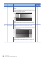
32-bit data assurance
1
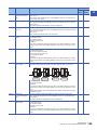
The link relay (LB) and link register (LW) data can be assured in units of 32 bits.
When LB and LW are set with the following four conditions met, 32-bit data assurance is automatically assured.
• The start device number of LB is a multiple of 20H.
• The number of points assigned per station in LB is a multiple of 20H.
• The start device number of LW is a multiple of 2.
• The number of points assigned per station in LW is a multiple of 2.
LB and LW are specified under "Network Range Assignment" in "Required Settings" of the control station. ( Page 54
Network Range Assignment)
■Data assurance at the time of link refresh
Link-refreshing the link devices that satisfy the conditions for 32-bit data assurance will ensure the integrity of 32-bit data.
CPU module
CC-Link IE Controller
Network-equipped module
Device or global label
LW
0H
1H
2H
3H
4H
5H
6H
7H
2 words
(32 bits)
2 words
(32 bits)
2 words
(32 bits)
2 words
(32 bits)
2 words
(32 bits)
Link refresh
2 words
(32 bits)
2 words
(32 bits)
2 words
(32 bits)
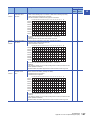
■Data integrity assurance at the time of direct access to link devices
Directly accessing link devices that satisfy the conditions for 32-bit data assurance will ensure the integrity of 32-bit data.
BMOV J1\W0 W0 K8
CPU module
Link register (W)
0H
1H
2H
3H
4H
5H
6H
7H
CC-Link IE Controller
Network-equipped module
Link register (LW)
0H
2 words
(32 bits)
2 words
(32 bits)
2 words
(32 bits)
2 words
(32 bits)
2 words
(32 bits)
2 words
(32 bits)
4H
2 words
(32 bits)
2 words
(32 bits)
6H
1H
2H
3H
5H
7H
1 FUNCTIONS
1.1 Cyclic Transmission
23
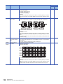
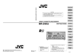
Station-based block data assurance
Integrity of the cyclic data is assured for each station by handshake between the CPU module and CC-Link IE Controller
Network-equipped module for a link refresh.
■Setting
Set station-based block data assurance under "Supplementary Cyclic Settings" in "Application Settings" of the control station.
( Page 63 Supplementary Cyclic Settings)
Once this setting is enabled on the control station, integrity of the data for all stations is assured for each station.
■Access to link devices
During a link refresh, data are assured for each station as shown below.
24
CPU module
Device or global label
CC-Link IE Controller
Network-equipped module
Link device
Data
assurance
Station No.1
Station No.1
Data
assurance
Data
assurance
Station No.2
Station No.2
Data
assurance
Data
assurance
Station No.3
Station No.3
Data
assurance
Data
assurance
Station No.4
Station No.4
Data
assurance
Link refresh
1 FUNCTIONS
1.1 Cyclic Transmission
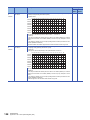
Interlock program
1
Data of more than 32 bits can be assured with the station-based block data assurance setting disabled.
Handshake using link relay (LB) data can prevent data inconsistency of the link register (LW) because link relay (LB) is sent
after link register (LW).
Ex.
The following shows a program example of when 'uData' (W0 to W2) of the control station is sent to 'uData' (W0 to W2) of the
normal station.
Handshake is performed by turning on 'bHandShake1' (B0) in the control station and 'bHandShake2' (B100) upon completion
of storing send data.
Control station
(station No.1)
Normal station
(station No.2)
Sending
station
Receiving
station
CC-Link IE Controller
Network-equipped module
CC-Link IE Controller
Network-equipped module
■Data flow
Send
request
Send data (W)
SET B0
CPU module Control station
B0 Station
Station LB0
No.1
No.1
B100 Station
Station LB100
No.2
No.2
W0
LW0
Station
No.1
Station
No.1
Station
No.2
Station
No.2
W100
Normal station CPU module
LB0 Station
Station B0
No.1
No.1
LB100 Station
Station B100
No.2
No.2
B0
Receive data (W)
W0
LW0
Station
No.1
Station
No.1
Station
No.2
Station
No.2
W100
LW100 LW100
Cyclic transmission
Link refresh
1 FUNCTIONS
1.1 Cyclic Transmission
25
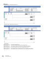
■Program
• Sending station: Control station (station No.1)
Classification
Description
Label to be defined
Define global labels as shown below:
• Receiving station: Normal station (station No.2)
Classification
Description
Label to be defined
Define global labels as shown below:
• Program flow
Sending station (10)
26
The 'bSendRequest' (M0) is turned on.
Sending station (10)
The contents of 'uOutputData' (D0 to D2) is stored in 'uData' (W0 to W2).
Sending station (10)
Upon completion of storage in 'uData' (W0 to W2), 'bHandShake1' (B0) is turned on.
Receiving station (10)
Link relay (LB) is sent through cyclic transmission and 'bHandShake1 (B0) is turned on.
Receiving station (10)
The contents of 'uData' (W0 to W2) is stored in 'uOutputData' (D100 to D102).
Receiving station (10)
Upon completion of storage in 'uOutputData' (D100 to D102), 'bHandShake2' (B100) is turned on.
Sending station (18)
When 'bHandShake2' (B100) in the receiving station is turned on, 'bHandShake1' (B0) is turned off.
1 FUNCTIONS
1.1 Cyclic Transmission
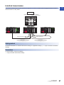
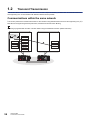
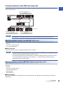
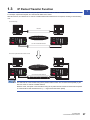
Interlink transmission
1
This function transfers data in the link devices (LB, LW)of the CC-Link IE Controller Network-equipped module to another
network module on a relay station.
Relay station
Network module
CC-Link IE Controller
Network-equipped module
RX
RY
Data of network No.2
Network No.1
LB
Interlink
transmissions
Data of network No.1
Network No.2
Setting method
Set interlink transmission in "Interlink Transmission Settings" in "Application Settings". ( Page 70 Interlink Transmission
Settings)
Precautions
For the precautions, refer to the following.
Page 70 Interlink Transmission Settings
1 FUNCTIONS
1.1 Cyclic Transmission
27
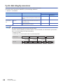
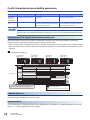
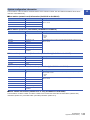
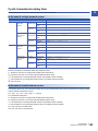
Cyclic transmission punctuality assurance
The link scan time is constant using the following methods.
Method
Description
Advantage
Disadvantage
Specification of
the number of
transient
transmissions
Specify the number of transient
transmissions within one link scan.
The link scan time can be minimized while it is
kept constant.
If the network status is unstable, the link scan
time may not be kept constant.
Constant link
scan
Specify the link scan time.
Even If the network status is unstable or the
number of transient transmissions varies, the link
scan time can be kept constant.
If the actual link scan time is longer than the link
scan time specified, the operation is performed
based on the actual link scan time.
While this function is used to keep the link scan time constant, the transmission delay time is not kept constant
by this function. The transmission delay time is affected by a factor such as a prolonged sequence scan time.
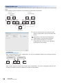
Specification of the number of transient transmissions
When the fluctuation in link scan time needs to be eliminated, the link scan time can be kept constant by performing a
specified number of transient transmissions during one link scan at each station.
• When the actual number of transient transmissions is less than the specified one: Dummy data is sent to cover the shortfall.
• When the actual number of transient transmissions exceeds the specified one: They are divided and transmitted in several
link scans.
Ex.
When the specified number is 2
Control station
(station No.1)
Normal station
(station No.2)
Normal station
(station No.3)
Normal station
(station No.4)
Request
Link scan time
Response
Link scan time is constant since each station sends
a specified number of transient transmissions.
Cyclic transmission
Transient transmission
Transient transmission (dummy transmission)
Constant link scan
If the network status is unstable, the link scan time can be kept constant by specifying the link scan time at the control station
to allow for possible fluctuations in the link scan time.
Setting method
Set cyclic transmission punctuality assurance under "Supplementary Cyclic Settings" in "Application Settings" of the control
station. ( Page 63 Supplementary Cyclic Settings)
28
1 FUNCTIONS
1.1 Cyclic Transmission
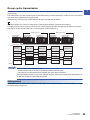
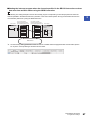
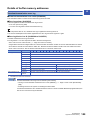
Group cyclic transmission
1
This function is used to divide the stations within the network into groups and specify the stations that share cyclic data
(shared group).
This setting allows cyclic data to be shared among the stations having the same shared group number and not to be received
from those having a different shared group number.
Stations having no shared group number assigned will share cyclic data with all stations.
Ex.
The station (station No.1) having no shared group number assigned will share cyclic data with all stations.
The stations (station No.2 to 5) having a shared group number assigned will share cyclic data with the stations of the same
shared group number and the station without a shared group number (station No.1).
Shared group No.1
Control station
(station No.1)
Normal station
(station No.2)
Normal station
(station No.3)
Shared group No.2
Normal station
(station No.4)
Normal station
(station No.5)
Link relay (LB)
LB0
Station No.1
send range
Station No.1
Station No.1
Station No.2
Station No.2
send range
Station No.2
Station No.3
Station No.3
Station No.3
send range
Station No.1
Station No.1
Station No.4
Station No.4
send range
Station No.4
Station No.5
Station No.5
Station No.5
send range
LB7FFF
Use this function for the following purposes.
• All stations need to share the data of the station controlling production lines.
• Data sharing is not desired between the stations that control different machines.
Since each station receives only the cyclic data from any given stations, the number of link refresh points can
be reduced, resulting in a shorter link refresh time.
Setting method
Set the group cyclic transmission under "Network Range Assignment" in "Required Settings" of the control station. ( Page
54 Network Range Assignment)
1 FUNCTIONS
1.1 Cyclic Transmission
29
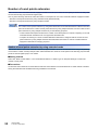
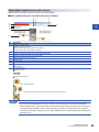
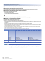
Number of send points extension
When one CC-Link IE Controller Network-equipped module is mounted, the number of send points per station are 16K points
for both the link relay (LB) and the link register (LW).
Use any of the following methods to extend the number of send points for CC-Link IE Controller Network-equipped modules.
• Number of send points extension by using extended mode (Recommended)
• Number of send points extension by using multiple modules
The number of send points extension by using extended mode is recommended because it allows more send
points to be set than the number of send points extension by using multiple modules. Use the number of send
points extension by using multiple modules only for the following purposes.
• To add a station that requires more than the number of 16K send points in a network comprising CC-Link IE
Controller Network modules that do not support the extended mode
• To replace an existing CC-Link IE Controller Network module that is configured with the number of send
points extension by using multiple modules with a MELSEC iQ-R series CC-Link IE Controller Networkequipped module without changing programs
Number of send points extension by using extended mode
This function allows a CC-Link IE Controller Network-equipped module to be set to the extended mode using an engineering
tool so that the number of send points per station will be extended to a maximum of 32K points for the link relay (LB) and 128K
points for the link register (LW) in one module.
■Setting method
Select "Ext. Mode Control Station" or "Ext. Mode Normal Station" in "Station Type" of "Required Settings" to extend the
number of send points.
■Precautions
Set both the control station and normal stations within the same network to the extended mode. A mixed network of stations
having the extended mode enabled and having it disabled is not allowed.
30
1 FUNCTIONS
1.1 Cyclic Transmission
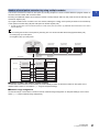
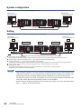
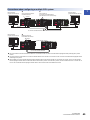
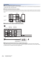
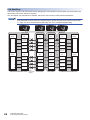
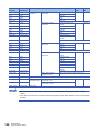
Number of send points extension by using multiple modules
1
This function increases the number of send points by mounting multiple CC-Link IE Controller Network-equipped modules of
the same network number with one CPU module.
Mounting one additional module can increase the number of send points per station by 16K points for both the link relay (LB)
and the link register (LW).
Up to eight modules can be mounted on one CPU module, allowing the number of send points per station to be extended up
to 32K points for the link relay (LB) and 128K points for the link register (LW). *1
*1
Number of send points cannot exceed the maximum number of link points per network. ( MELSEC iQ-R Ethernet/CC-Link IE User's
Manual (Startup))
Ex.
When increasing the number of send points by mounting two CC-Link IE Controller Network-equipped modules (LW)
• Link relay (LB): Up to 32K points
• Link register (LW): Up to 32K points
Control station
(station No.1)
Normal station
(station No.2)
Normal station
(station No.3)
Control station
(station No.1)
Normal station
(station No.2)
W
LW
LW
16K max.
Control station
(station No.1)
Control station
(station No.1)
Control station
(station No.1)
16K max.
Normal station
(station No.2)
CPU module
Normal station
(station No.3)
Normal station
(station No.4)
Normal station
(station No.5)
Normal station
(station No.4)
Normal station
(station No.5)
Normal station
(station No.2)
Normal station
(station No.3)
Normal station
(station No.4)
Normal station
(station No.5)
Normal station
(station No.3)
Normal station
(station No.4)
Normal station
(station No.5)
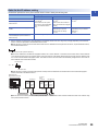
■Network number and station number setting
Set the same network number to the modules (1st to 8th module) for which to extend the number of send points. Set a
different station number to each station. ( Page 52 Required Settings)
■Network range assignment
Set the send range of each station in LB and LW under "Network Range Assignment" of "Required Settings" of the control
station. ( Page 54 Network Range Assignment)
1 FUNCTIONS
1.1 Cyclic Transmission
31
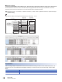
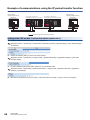
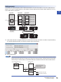
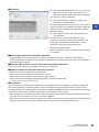
■Refresh settings
Configure the refresh settings so that within the own station send range of the CPU module, the range of up to 16K points can
be link-refreshed to the first CC-Link IE Controller Network-equipped module and the range to be extended can be linkrefreshed to the second and subsequent CC-Link IE Controller Network-equipped modules.
Navigation window [Parameter] [Module Information] Target module [Module Parameter] [Basic Settings]
[Refresh Setting]
Ex.
When the own station send range is link-refreshed to the station No. 1 and 2
Control station
(station No.1)
Normal station
(station No.2)
B/W
LB/LW
LB/LW
Control station
(station No.1)
Control station
(station No.1)
Control station
(station No.1)
CPU module
Own station
send range
Normal station
(station No.2)
Normal station
(station No.2)
Normal station
(station No.3)
Normal station
(station No.4)
Normal station
(station No.5)
Normal station
(station No.3)
Normal station
(station No.4)
Normal station
(station No.5)
Normal station
(station No.3)
Normal station
(station No.4)
Normal station
(station No.5)
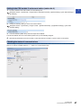
• Network range assignment
• Refresh settings of the control station (station No.1)
• Refresh settings of the normal station (station No.2)
Precautions
When mounting multiple modules with the same network number and using a function, such as the link direct device, that
specifies a CC-Link IE Controller Network-equipped module by the network number, the execution target will be as listed
below.
32
Item
Description
Link direct devices
The module mounted on the slot with the smallest slot number in the base unit is targeted.
Dedicated instruction
The module mounted on the slot with the smallest slot number in the base unit executes the dedicated instruction.
1 FUNCTIONS
1.1 Cyclic Transmission
Reception status when an error occurs
1
When there is a data link faulty station on the CC-Link IE Controller Network, the link device statuses are as follows.
• Normally operating station: Holds the data received from the faulty station immediately before the error.
• Faulty station: Holds the data received from the other stations immediately before the error.
Control station
(station No.1)
Normal station Faulty station
(station No.2)
Normal station
(station No.3)
LB/LW
Station No.1
send range
Station No.1
receive range
Station No.1
receive range
Station No.2
receive range
Station No.2
send range
Station No.2
receive range
Station No.3
receive range
Station No.3
receive range
Station No.3
send range
Data transferred
Data held
Cyclic transmission stop and restart
This function is used to stop the cyclic transmission during debugging and other operations. (Data reception from other
stations and data sending from the own station are stopped.) Also, the stopped cyclic transmission is restarted. Transient
transmission does not stop.
Cyclic transmission is stopped and restarted using the link start/stop of the CC-Link IE Controller Network diagnostics.
( Page 86 Link Start/Stop)
1 FUNCTIONS
1.1 Cyclic Transmission
33
1.2
Transient Transmission
This function allows communications with other stations when a request is made by a method such as a dedicated instruction
and engineering tool. Communications with different networks is also possible.
Communications within the same network
This function performs the transient transmission to other stations using dedicated instructions and the engineering tool. (
MELSEC iQ-R Programming Manual (Instructions, Standard Functions/Function Blocks))
Ex.
Accessing a programmable controller of another station using the dedicated instruction (READ instruction)
Control station
CPU module
Command
CPU module
Channel 1
Channel 2
READ
Device
3
1234H
34
Normal station
1
Channel 3
Channel 4
Channel 5
Channel 6
Channel 7
Channel 8
Channel 9
Channel 10
1 FUNCTIONS
1.2 Transient Transmission
2
Device
1234H
Communications with different networks
1
This function performs the transient transmission seamlessly to stations on different networks using dedicated instructions
and the engineering tool.
CC-Link IE Controller Network
Network No.1
Engineering tool
(Relay station)
Ethernet
CC-Link IE Field Network
Network No.3
Network No.2
Communications can be made with stations up to eight networks apart (number of relay stations: 7).
When the networks consist of only MELSEC iQ-R series
Communication paths are automatically set for communication with the following networks of MELSEC iQ-R series.
• Ethernet
• CC-Link IE Controller Network
• CC-Link IE Field Network
■Setting method
Check that "Dynamic Routing" in "Application Settings" is set to "Enable".
• Communication paths are automatically set, but they can also be manually set. ( Page 35 When the
networks consist of MELSEC iQ-R series and other series)
• Communication paths cannot be automatically set to Ethernet-equipped modules connected via a router.
Set communication paths manually for such modules. ( Page 35 When the networks consist of
MELSEC iQ-R series and other series)
When the networks consist of MELSEC iQ-R series and other series
Setting communication paths allows communication with the following networks configured with modules other than MELSEC
iQ-R series.
• Ethernet
• CC-Link IE Controller Network
• CC-Link IE Field Network
• MELSECNET/H
• MELSECNET/10
■Setting method
Set communication paths in "Routing Setting" of the CPU parameters. ( MELSEC iQ-R CPU Module User's Manual
(Application))
1 FUNCTIONS
1.2 Transient Transmission
35
Communication test
Communication test checks if transient transmission data can be properly routed from the own station to the communication
target.
Take the following system configuration as an example of communication test procedure.
CC-Link IE
Controller Network
CC-Link IE
Controller Network
Own station
(request source)
Station
No.2
Station
No.1
Network No.1
Station
No.3
Station
No.4
Station
No.1
Station
No.2
Network No.3
(Relay
station 2)
Station Station
Station
No.2
No.3
No.4
(Relay
station 1)
Station
No.1
Communication
target
Network No.2
Station
No.3
CC-Link IE
Field Network
1.
Open the "Communication Test" window and enter
values for "Target Station" and "Communication Data
Setting".
[Diagnostics] [CC-Link IE Control Diagnostics
(Optical Cable)] [Communication Test] button
2.
Click the [Execute Test] button to execute the
communication test. If an error occurs, take actions
according to the error message.
Precautions
• When a relay sending station is set to "Target Station", only an error code appears without an error message. Set a relay
receiving station to "Target Station".
Network No.2
Network No.1
Station
No.1
Own station
(request source)
Station
No.2
Station
No.1
Station
No.2
Receiving
Sending
(relay) station (relay) station
• When a station mounted to the same CPU module is set to "Target Station", only an error code appears without an error
message. Set a station mounted to a different CPU module to "Target Station".
36
1 FUNCTIONS
1.2 Transient Transmission
1.3
IP Packet Transfer Function
1
This function enables communications using the specified IP address over CC-Link IE Controller Network.
For example, a personal computer can communicate with the FTP server.
With this function, two networks of CC-Link IE Controller Network and Ethernet are not required, resulting in reduced wiring
cost.
Conventional way
Ethernet
Two networks were required.
CC-Link IE Controller Network
When the IP packet transfer function is used
Only CC-Link IE Controller Network
is required to perform communications
using an IP address.
CC-Link IE Controller Network
Ethernet communications (IP packet transfer)
The data that are communicated using the IP packet transfer function are communicated separately by the
link scan of the CC-Link IE Controller Network.
Because of this, the speed of communications using the IP packet transfer function is slower than the speed
of communications with the Ethernet line. ( Page 48 Communication speed)
1 FUNCTIONS
1.3 IP Packet Transfer Function
37
System configuration
Connect an Ethernet device to an Ethernet-equipped module.
Ethernet device
(request source device)
Ethernet device
(request destination device)
Ethernet
Ethernet
CC-Link IE Controller Network
Setting
To use the IP packet transfer function, the following items need to be set.
Ethernet device
(request destination device)
Ethernet device
(request destination device)
Ò
Ò
Ó, Ô, Õ, Ö
Õ, Ö
Ó, Ô, Õ, Ö
Ethernet
: Communication route
Ethernet
CC-Link IE Controller Network
Ethernet device gateway address setting
Set the IP address of the Ethernet-equipped module connected to an Ethernet device in the gateway address of the Ethernet device used.
IP address setting of the Ethernet-equipped module ( Page 40 Setting in the Ethernet-equipped module)
IP packet transfer setting ( Page 40 Setting in the Ethernet-equipped module)
This setting is required for the IP packet to be passed between an Ethernet-equipped module and a CC-Link IE Controller Network-equipped module.
IP address setting of the CC-Link IE Controller Network-equipped module (Page 40 Setting in the control station)
Routing parameter setting
When modules other than MELSEC iQ-R series exist in the communication route, communication route setting is required.
(MELSEC iQ-R CPU Module User's Manual (Application))
• When the Ethernet device is a personal computer (only Ethernet devices having the route command, such
as Microsoft Windows), it is recommended to set the gateway address using the route command. If the
gateway address is set in the default gateway, packets not related to the IP packet transfer are also
transmitted through the CPU module. Consequently, the service processing of the CPU module drops under
heavy load, causing other service processings to be slow or other problems.
• After the setting is completed, execute the IP communication test to check for an error in the communication
path. ( Page 41 IP communication test)
38
1 FUNCTIONS
1.3 IP Packet Transfer Function
Rules for the IP address setting
1
IP addresses specified for the IP packet transfer function need to satisfy the following rules.
Device to be set
Setting range of the IP address
Ethernet device
Ethernet-equipped module connected to the
Ethernet device
CC-Link IE Controller Network-equipped
module
Ethernet-equipped module on the
communication path (not connected to an
Ethernet device)
*1
First and second octets
Third octet
Fourth octet
0.0 to 223.255*1
(Same numbers for the request
source device, request destination
device, and modules between
them)
, ,
1 to 239*1
(Same number for the Ethernet
device and the Ethernet-equipped
module)
1 to 120*1
,
Automatically set (network
number of the own station)
1 to 239
Automatically set (Own station's
station No.)
1 to 120
IP address setting not required
Set the numbers according to the range applicable to the Ethernet device used. The range may not apply depending on the Ethernet
device. Check the specifications of the Ethernet device used.
Use the same numbers for the first and second octets of the IP addresses of the request source device, request destination device,
and modules between them.
192 . 168 . 10 . 36
The first and second octets (network addresses)
For the IP addresses of the Ethernet-equipped modules, set a number between 1 and 239 for the third octet and a number between
1 and 120 for the fourth octet. The network number of the own station is automatically assigned to the third octet of the IP address of the
CC-Link IE Controller Network-equipped module. The station number of the own station is automatically assigned to the fourth octet of
the IP address of the master/local module.
The third octet
192 . 168 . 10 . 36
The fourth octet
Use the same number for the third octet (network number) of the IP addresses of an Ethernet device and a Ethernet-equipped
module connected to the Ethernet device.
Ethernet device
(request source device)
192.168.2.1
Ethernet- Control
equipped station
module
(station
No.1)
192.168.10.11
192.168. 10.36
Network No.10
IP address
setting
not required
192.168.7.18
Ethernet- Normal
equipped station
module
(station
No.8)
Normal
station
(station
No.18)
192.168. 2.8
Network No.2
Do not use the third octet (network number) of the IP address same as that of other network modules and other CPU modules using
the IP packet transfer function.
1 FUNCTIONS
1.3 IP Packet Transfer Function
39
Do not use the same network numbers for those highlighted.
Network No.32
Ethernet*2
192.168.21.1
192.168.10.1
192.168.10.2
Network No.10
Ethernet
*2
192.168.21.2
Network No.2
CC-Link IE Controller Network
Network No.21
Ethernet
Do not use the same network numbers for those of network modules other than the CC-Link IE Controller Network-equipped module.
When setting the IP address in each device, do not use the IP addresses already used for other devices.
Setting method
For a communication example, refer to the following.
Page 46 Example of communications using the IP packet transfer function
■Setting in the Ethernet-equipped module
1.
Set the IP address of the Ethernet-equipped module in the following item.
Navigation window [Parameter] Target module [Module Parameter] [Basic Settings] [Own Node Settings]
[IP Address]
Follow the rules to set the IP address. ( Page 39 Rules for the IP address setting)
2.
Change the following setting to "Use".
Navigation window [Parameter] Target module [Module Parameter] [Application Settings] [IP Packet
Transfer Setting]
■Setting in the control station
1.
Set the IP address of the control station in the following item.
Navigation window [Parameter] [Module Information] Target module [Module Parameter] [Application
Settings] [IP Address]
Follow the rules to set the IP address. ( Page 39 Rules for the IP address setting)
■Setting in the normal stations
The IP address setting is not required for the normal stations. The same network address as the control station is
automatically assigned to the first and second octets. The network number of the own station is assigned to the third octet,
and the station number of the own station is assigned to the fourth octet.
Routing parameter setting
When modules other than MELSEC iQ-R series exist in the communication route, set routing parameters.
To set routing parameters, refer to the following.
MELSEC iQ-R CPU Module User's Manual (Application)
40
1 FUNCTIONS
1.3 IP Packet Transfer Function
IP communication test
1
This function checks whether no error occurs in the communication path within CC-Link IE Controller Network when the IP
packet transfer function is used. The following can be checked using the IP communication test:
• Cables are properly connected on the communication path
• Parameters related to the IP packet transfer function, such as an IP address and routing parameters, are correctly set on
the communication path.
• All the CPU modules and CC-Link IE Controller Network modules on the communication path support the IP packet transfer
function.
The following system configuration is used to explain the procedure of the IP communication test.
The IP communication test allows the communication paths in the dotted line above to be checked.
The IP communication test cannot be executed if the engineering tool is connected to RJ71EN71. Use one of
the following methods to check whether no error occurs in the communication path.
• Execute a PING test in the Ethernet diagnostics. ( MELSEC iQ-R Ethernet User's Manual (Application))
• Execute a PING from the Ethernet device connected.
Ethernet device
(request source
device)
CPU module 1: 192.168.1.10
Control station (station No.1): 192.168.2.1
Ethernet device
(request destination
device)
CPU module 2: 192.168.10.10
Normal station (station No.2): 192.168.2.2
192.168.1.1
192.168.10.1
Network No.2
Network No.1
1.
Network No.10
Open the "IP Communication Test" window. Enter the IP address of the CPU module 2 or the normal station (station
No.2) connected to the request destination device in "Communication Target".
[Diagnostics] [CC-Link IE Control Diagnostics (Optical Cable)] [IP Communication Test] button
2.
Click on the [Execute Test] button to execute the test. When the test is completed, the route to the device set in
"Communication Target" is displayed on the underside of the window. If the test fails, click the [Details] button in the
"Error Information" area to check the error information.
1 FUNCTIONS
1.3 IP Packet Transfer Function
41
• If the cause cannot be identified from the error information after the IP communication test is executed, or
communications cannot be performed even though the IP communication test is completed successfully,
follow the troubleshooting instructions (on when the IP packet transfer function is used) and take corrective
actions. ( Page 91 When IP communications cannot be performed using the IP packet transfer function)
• Up to 127 levels of modules can be connected when the IP communication test is executed.
• When an Ethernet device (request destination device) is connected to an Ethernet-equipped module, the
communication path to the Ethernet-equipped module connected to the Ethernet device (request
destination device) or CC-Link IE Controller Network-equipped module can be checked using the IP
communication test. Setting the IP address of the Ethernet device in "Communication Target" on the "IP
Communication Test" window causes an error. (Error code of the CPU module: 4A2AH)
Precautions
• When the IP address of a relay sending station is set to "Communication Target", only an error code appears without any
information displayed in "Error Information". Set the IP address of the Ethernet-equipped module or the CC-Link IE
Controller Network-equipped module connected to the request destination device to "Communication Target".
• When the IP address of a CC-Link IE Controller Network-equipped module mounted to the same CPU module is set to
"Communication Target", only an error code appears without any information displayed in "Error Information". Set the IP
address of a CC-Link IE Controller Network-equipped module mounted to a different CPU module to "Communication
Target".
• Communications cannot be performed via modules that do not support the IP packet transfer function such as
MELSECNET/H. Only an error code appears without any information displayed in "Error Information".
42
1 FUNCTIONS
1.3 IP Packet Transfer Function
Relay using CC-Link IE Field Network
1
The IP packet transfer function can be used through a relay from CC-Link IE Field Network to CC-Link IE Controller Network.
Request destination 3
Request destination 2
Ethernet
Ethernet
CC-Link IE Controller Network
Relay station
CC-Link IE Field Network
Ethernet
Ethernet
Request destination 1
Request source
When using the IP packet transfer function on CC-Link IE Field Network, refer to the following.
User's manual for the CC-Link IE Field Network used
1 FUNCTIONS
1.3 IP Packet Transfer Function
43
Precautions
Support for the IP packet transfer function
MELSEC iQ-R series modules support the IP packet transfer function from the first release.
To check whether other modules support the IP packet transfer function, refer to the following.
User's manual for the module used
Using different networks
Communications cannot be performed via modules that do not support the IP packet transfer function such as MELSECNET/
H.
Communications before a baton pass is established (the D LINK LED turns off)
The IP packet transfer function can be used after a baton pass was established. If communications are performed before that,
a timeout error occurs in an Ethernet device (request source device). Whether the baton pass is established in the own station
can be checked on the D LINK LED.
Precautions when using the UDP communication
Using UDP may reduce the reliability of data communications compared to TCP, causing a problem, such as data missing and
changed order of data receiving. If any problem occurs, change the protocol to TCP.
Communications of Broadcast and Multicast
Communications of Broadcast and Multicast cannot be transferred using the IP packet transfer function. Use Unicast
(identifying a single request destination) instead.
44
1 FUNCTIONS
1.3 IP Packet Transfer Function
Precautions when configuring a multiple CPU system
Ethernet device
(request source device)
Ò
CPU module connected to
an Ethernet device
Ó
CPU module on
CC-Link IE Controller Network
(No restrictions on the control CPU)
1
Ethernet device
(request destination device)
Control
Ethernet
Ethernet
CC-Link IE Controller Network
Ethernet device
(request source device)
Ô
Module mounted on
the smallest slot number
Control
Same network number
Ethernet
CC-Link IE Controller Network
Set a CPU module connected to an Ethernet device as a control CPU of the CC-Link IE Controller Network-equipped module performing the IP packet
transfer.
Any CPU module in a relay station on CC-Link IE Controller Network can be served as a control CPU of the CC-Link IE Controller Network-equipped module
transferring the IP packet.
When multiple CC-Link IE Controller Network-equipped modules with the same network number are connected to one system, the CC-Link IE Controller
Network-equipped module with the smallest slot number transfers the IP packet. To transfer the IP packet, connect the Ethernet device to a control CPU of
the CC-Link IE Controller Network-equipped module with the same network number and smallest slot number.
1 FUNCTIONS
1.3 IP Packet Transfer Function
45
Example of communications using the IP packet transfer function
The following system configuration is used to explain an example of communications.
Ethernet device
(request source device)
Ethernet device
(request destination device)
CPU module 1: 192.168.1.10
Control station (station No.1): 192.168.2.1
192.168.1.1
CPU module 2: 192.168.10.10
Normal station (station No.2): 192.168.2.2
192.168.10.1
Network No.2
Network No.1
Network No.10
: Route through which IP packets are passed
Setting in the CPU module 1 and control station (station No.1)
1.
Set the IP address of the CPU module 1 in the following item.
Navigation window [Parameter] Target module [Module Parameter] [Basic Settings] [Own Node Settings]
[IP Address]
2.
Change the following setting to "Use" in the CPU module 1.
Navigation window [Parameter] Target module [Module Parameter] [Application Settings] [IP Packet
Transfer Setting]
3.
Set the IP address of the control station (station No.1) in the following item.
Navigation window [Parameter] [Module Information] Target module [Module Parameter] [Application
Settings] [IP Address]
4.
46
Write the set parameters to the CPU module 1. Then reset the CPU module 1 or power off and on the system.
1 FUNCTIONS
1.3 IP Packet Transfer Function
Setting in the CPU module 2 and normal station (station No.2)
1.
1
Set the IP address of the CPU module 2 in the following item.
Navigation window [Parameter] Target module [Module Parameter] [Basic Settings] [Own Node Settings]
[IP Address]
2.
Change the following setting to "Use" in the CPU module 2.
Navigation window [Parameter] Target module [Module Parameter] [Application Settings] [IP Packet
Transfer Setting]
3.
The normal station (station No.2) does not require an IP address.
The network address set in the control station (station No.1) is automatically assigned.
4.
Write the set parameters to the CPU module 2. Then reset the CPU module 2 or power off and on the system.
Checking the status of communications
After the setting is completed in each module, execute the IP communication test to check for an error in the communication
path on CC-Link IE Controller Network. ( Page 41 IP communication test)
1 FUNCTIONS
1.3 IP Packet Transfer Function
47
Communication speed
This section provides the results of communication speed measured using the IP packet transfer function. Use the results as
a reference.
System configuration
The results are based on measurement when FTP communications are performed with four CC-Link IE Controller Networkequipped modules connected in the network.
• When a request source device and a request destination device are connected to a CPU module
Ethernet device (request source device)
<FTP client>
Ethernet device (request destination device)
<FTP server>
Ethernet
Ethernet
CC-Link IE Controller Network
• When a request source device and a request destination device are connected to RJ71EN71
Ethernet device (request source device)
<FTP client>
Ethernet device (request destination device)
<FTP server>
Ethernet
Ethernet
CC-Link IE Controller Network
48
Device
Description
Ethernet device (request source
device)
<FTP client>
CPU
Intel Core 2 Duo processor 2.00GHz
OS
Microsoft Windows 7 Professional Operating System
Ethernet board
1000BASE-T
FTP server application
FFFTP
Ethernet device (request
destination device)
<FTP server>
CPU
Intel Core i5 Duo processor 2.67GHz
OS
Microsoft Windows 7 Professional Operating System
Ethernet board
1000BASE-T
FTP client application
FileZilla Server
Programmable controller
CPU module
• R04CPU
• Sequence scan time: 1ms
CC-Link IE Controller Network
• Cyclic transmission: 128 points assigned to each station for the "LB/LW
Setting", 256 points assigned to each station for the "LX/LY Setting"
• Transient transmission: N/A
1 FUNCTIONS
1.3 IP Packet Transfer Function
Measurement result of the communication speed
1
The following table lists the time that takes until a file is read from a request source device to a request destination device.
Size of a file to be
communicated
When a request source device and a request
destination device are connected to a CPU module
When a request source device and a request
destination device are connected to RJ71EN71
1K bytes
10ms
10ms
50K bytes
300ms
100ms
100K bytes
600ms
200ms
1M bytes
4000ms
2000ms
To increase communication speed
Communication speed can be increased by checking the following items again.
■Sequence scan of a CPU module
Shortening sequence scan time can increase communication speed.
For causes extending sequence scan time, refer to the following.
MELSEC iQ-R CPU Module User's Manual (Application)
■Transient transmission frequency
Communications using the IP packet transfer function are performed with transient transmission. Taking one of the following
actions can increase communication speed.
• Executing the COM instruction on a program and executing a service processing at any timing other than an END
processing increase the frequency of transient transmission (the amount of processing per transient transmission).
Consequently, the frequency of communications using the IP packet transfer function increases, resulting in increased
communication speed. ( MELSEC iQ-R Programming Manual (Instructions, Standard Functions/Function Blocks))
• Decreasing the number of other transient transmission ensures the processing time of the IP packet transfer function;
therefore, communication speed can be increased.
■Link scan time
Minimizing the number of points of the "LB/LW Setting" and "LX/LY Setting" shortens link scan time, resulting in increased
communication speed.
1 FUNCTIONS
1.3 IP Packet Transfer Function
49
1.4
Interrupt Request to CPU Module
This function makes an interrupt request to the CPU module to start the interrupt program if the interrupt conditions preset
using the engineering tool are met.
Interrupt conditions are based on the changes in the link devices (LB, LW, LX) and the network statuses (SB, SW) checked
every link scan or the data reception status of the channel specified via the RECVS instruction.
CPU module
CC-Link IE Controller
Network-equipped module
Conditions
met
Main routine program
FEND
I50
Interrupt
condition check
Link device
(LB, LW, LX) change
Network status
(SB, SW) change
Interrupt program
IRET
END
Data reception status
of specified channel
Channel 1
Channel 2
Channel 3
Channel 4
Channel 5
Channel 6
Channel 7
Channel 8
RECVS
instruction
Setting method
Set the interrupt request to the CPU module in "Interrupt Settings" under "Application Settings". ( Page 64 Interrupt
Settings)
50
1 FUNCTIONS
1.4 Interrupt Request to CPU Module
1.5
Loopback Function
1
This function continues data link with normally operating stations even if a cable disconnection or faulty station occurs.
Cable disconnection
Even if a cable disconnection occurs, the system automatically performs loopback to continue the data link.
Disconnection
Control station
(station No.1)
Normal station
(station No.2)
Normal station
(station No.3)
Normal station
(station No.6)
Normal station
(station No.5)
Normal station
(station No.4)
Occurrence of faulty stations
The system disconnects faulty stations and automatically performs loopback to continue the data link.
If two or more faulty stations occur, a station located between the faulty stations cannot perform data link.
However, when more than one station exists between the faulty stations, a normal station is changed to a sub-control station
and continues data link.
Control station
(station No.1)
Loopback station
Normal station
(station No.6)
Loopback station
Normal station
(station No.2)
Down
Down
Normal station
(station No.5)
Sub-control station
(station No.3)
Loopback station
Normal station
(station No.4)
Loopback station
Setting method
The loopback function remains effective at all times. No parameter setting is required.
1 FUNCTIONS
1.5 Loopback Function
51
2
PARAMETER SETTINGS
This chapter describes the parameter settings required for communications between the CC-Link IE Controller Networkequipped module and other stations.
2.1
1.
Setting Parameters
Add the CC-Link IE Controller Network-equipped module in the engineering tool.
Navigation window [Parameter] [Module Information] Right click [Add New Module]
2.
The required settings, basic settings, and application settings are included in the parameter settings. Select one of the
settings from the tree on the window shown below and set parameters.
Navigation window [Parameter] [Module Information] Target module [Module Parameter]
3.
4.
After setting parameters, click the [Apply] button.
Write the settings to the CPU module using the engineering tool.
[Online] [Write to PLC]
5.
The settings are reflected by resetting the CPU module or powering off and on the system.
2.2
Required Settings
Set the station type, network number, or other parameters for the CC-Link IE Controller Network-equipped module.
: Can be set, : Cannot be set
Item
52
Description
Availability
Control
station
Normal
station
Reference
Station Type
Set the station type of the CC-Link IE Controller Network-equipped module.
Page 53 Station Type
Network Number
Set the network number of the CC-Link IE Controller Network-equipped module.
Page 53 Network
Number
Station Number
Set the station number of the CC-Link IE Controller Network-equipped module.
Page 53 Station
Number
Network Range
Assignment
Set parameters of each stations (the number of points and assignment of link devices)
in the control station.
Page 54 Network
Range Assignment
2 PARAMETER SETTINGS
2.1 Setting Parameters
Station Type
Set the station type of the CC-Link IE Controller Network-equipped module.
Item
Description
Setting range
Station Type
Select whether to use the CC-Link IE Controller Network-equipped module as the control station or a
normal station. One control station can be set in a network.
Send points can be extended by selecting "Ext. Mode Control Station" or "Ext. Mode Normal Station".
(Page 31 Number of send points extension by using multiple modules)
• Control Station
• Normal Station
• Ext. Mode Control
Station
• Ext. Mode Normal
Station
(Default: Station type set in
the "Add New Module"
window.)
2
Network Number
Set the network number of the CC-Link IE Controller Network-equipped module.
Item
Description
Setting range
Network number
Set the network number of the CC-Link IE Controller Network-equipped module.
1 to 239
(Default: 1)
Station Number
Set the station number of the CC-Link IE Controller Network-equipped module.
Item
Description
Setting range
Setting Method
Select whether to set the station number in parameter editor or in program (UINI instruction). This item
can be set only for a normal station.
When selecting "Program", use the UINI instruction to set the number. ( MELSEC iQ-R Programming
Manual (Instructions, Standard Functions/Function Blocks)
• Parameter Editor
• Program
(Default: Parameter
Editor)
Station No.
Set the station number of the CC-Link IE Controller Network-equipped module.
• Station number can be set within the range set in "Total No. of Stations" in the "Network Range
Assignment" window in "Required Settings" of the control station. To set the larger value, change the
value in "Total No. of Stations" in the "Network Range Assignment" window beforehand.
• Set a station number different from those used in the same network.
To set the station number of a normal station in this setting, set "Setting Method" to "Parameter Editor".
1 to 120
(Default: 1 for control
station, 2 for normal
station)
2 PARAMETER SETTINGS
2.2 Required Settings
53
Network Range Assignment
Set parameters of normal stations (the number of points and assignment of link devices) in the control station.
• Network range assignments are set in the control station only. Normal stations perform cyclic transmission
according to the range assigned at the control station.
• When "LB/LW Setting (2)" is used, link scan time will be longer compared to using "LB/LW Setting (1)" only.
Setting procedure
The procedure for the network range assignment settings is shown below.
1.
Set the required items.
2.
Click the [Apply] button and close the "Network Range Assignment" window.
Setting items
54
Item
Description
Setting range
Total No. Stations
When setting "Station Type" to "Control Station" or "Ext. Mode Control Station", set the total number
of stations in a network.
• When any reserved station is required, include the number of reserved stations.
• When skipping a station number, specify the number to be skipped as a reserved station.
2 to 120
(Default: 2 (when the control
station number is 1) or the
control station number (when
the control station number is
other than 1))
Switch Windows
Select the "LB/LW Setting" window of the "LX/LY Setting" window.
• LB/LW Setting (1)
• LB/LW Setting (2)
• LX/LY Setting (1)
• LX/LY Setting (2)
(Default: LB/LW Setting (1))
Device Assignment
Method
Right-click in the "Network Range Assignment" window and select a link device assignment
method.
• Start/End: Enter the start and end numbers of link devices.
• Points/Start: Enter the points and start numbers of link devices.
• Start/End
• Points/Start
(Default: Start/End)
2 PARAMETER SETTINGS
2.2 Required Settings
Item
Batch
Setting
Equal
Assignment
Description
Setting range
Specify the start station and end station, and equally assign link devices to stations.
• Start Station: 1 to the end
station number
• End Station: Number set to
"Start Station" to the end
station number
• Start Device No.: Same as
"LB/LW Setting (1)", "LB/LW
Setting (2)", "LX/LY Setting
(1)", or "LX/LY Setting (2)".
• Number of Points: 16 to
32768 for LB, 1 to 131072
for LW
(Default: Blank)
2
• Start station: Enter the start station number of stations for which link devices are equally
assigned.
• End station: Enter the end station number of stations for which link devices are equally assigned.
• Start Device No.: Enter the start number of link devices to be equally assigned.
• Number of Points: Enter the total points of link devices to be equally assigned.
Identical
Point
Assignment
LB/LW Setting (1)
LB/LW Setting (2)
Assign the same points to each station's send range in LB/LW.
(Default: Blank)
Assign LB/LW points. (Page 14 Communications using LB and LW)
Normally, setting only "LB/LW Setting (1)" is enough for communication using LB/LW. Set "LB/LW
Setting (2)" in the following cases:
• When extending each station's send range without changing existing assignments (When
changing the LB/LW assignment, correct link refresh range of each station.) (Page 60
Refresh Setting))
• When intentionally dividing each station's send range into two (e.g. within and outside the link
refresh range)
When settings are configured with the following four conditions met, 32-bit data integrity is
automatically assured. (Page 22 Cyclic data integrity assurance)
• The start device number of LB is a multiple of 20H.
• The number of points assigned per station in LB is a multiple of 20H.
• The start device number of LW is a multiple of 2.
• The number of points assigned per station in LW is a multiple of 2.
(Default: Blank)
LB
Set the number of points (decimal) of LB sent by each station. (The sum
of "LB/LW Setting (1)" and "LB/LW Setting (2)")
16 to 16384 (set in increments
of 16 points)
When "Station Type" in "Required Settings" is set to "Ext. Mode Control
Station" or "Ext. Mode Normal Station"
16 to 32768 (set in increments
of 16 points)
Start
Set the start number of the LB range to be sent by each station.
0000H to 7FF0H (multiples of
16)
End
Set the end number of the LB range to be sent by each station.
000FH to 7FFFH (multiples of
16 - 1)
Points
Set the number of points (decimal) of LW sent by each station. (The sum
of "LB/LW Setting (1)" and "LB/LW Setting (2)")
1 to 16384 (set in increments
of 1 point)
When "Station Type" in "Required Settings" is set to "Ext. Mode Control
Station" or "Ext. Mode Normal Station"
1 to 131072 (set in increments
of 1 point)
LW
Points
Start
Set the start number of the LW range to be sent by each station.
0000H to 1FFFFH
End
Set the end number of the LW range to be sent by each station.
0000H to 1FFFFH
2 PARAMETER SETTINGS
2.2 Required Settings
55
Item
Description
Setting range
LX/LY Setting (1)
LX/LY Setting (2)
Assign LX/LY points. (Page 15 Communications using LX and LY)
Set "LX/LY Setting (1)" for block 1, and "LX/LY Setting (2)" for block 2.
Avoid duplication of the LX/LY settings for each station in "LX/LY Setting (1)" and "LX/LY Setting
(2)".
The LX/LY data of the same I/O numbers with the actual I/O (the range where actual modules are
mounted) must be refreshed to the area after the actual I/O area or to any other than LX/LY in
refresh settings. Refresh target CPU-side devices in refresh settings cannot overlap with the actual
I/O areas. (Page 60 Refresh Setting)
(Default: Blank)
M
Station
L
Station
LY
Points
Set the number of points (decimal) of the output range (LY) sent from the
M station (I/O master station) to the other station.
16 to 8192 (set in increments
of 16 points)
Start
Set the start number of the output range (LY) of the M station (I/O master
station).
0000H to 1FF0H (multiples of
16)
End
Set the end number of the output range (LY) of the M station (I/O master
station).
000FH to 1FFFH (multiples of
16 - 1)
Points
The number of points (decimal) of the input range (LX) received by the L
station (the station other than the I/O master station) from the M station is
displayed.
Start
Set the start number of the input range (LX) of the L station (the station
other than the I/O master station).
0000H to 1FF0H (multiples of
16)
End
The end number of the input range (LX) of the L station (the station other
than the I/O master station) is displayed.
Points
Set the number of points (decimal) of the input range (LX) received by the
M station (I/O master station) from the other station.
16 to 8192 (set in increments
of 16 points)
Start
Set the start number of the input range (LX) of the M station (I/O master
station).
0000H to 1FF0H (multiples of
16)
End
Set the end number of the input range (LX) of the M station (I/O master
station).
000FH to 1FFFH (multiples of
16 - 1)
Points
The number of points (decimal) of the output range (LY) sent from the L
station (the station other than the I/O master station) to the I/O master
station is displayed.
Start
Set the start number of the output range (LY) of the L station (the station
other than the I/O master station).
0000H to 1FF0H (multiples of
16)
End
The end number of the output range (LY) of the L station (the station other
than the I/O master station) is displayed.
Set an I/O master station for each block to perform communication using
LX/LY. Up to two I/O master stations can be set for one network (block 1
and block 2), regardless of the status of control or normal station.
• No Setting
• I/O Master Station
(Default: No Setting)
Reserved Station
Set to specify the normal station as a reserved station.
• No Setting: The normal station is connected to the network.
• Reserved Station: The normal station is reserved for future expansion. By reserving a normal
station, link device assignment will not change even if the normal station is added or the
reservation is cancelled. Therefore, the program needs not to be modified. Physical connection
of the normal station is not required.
• No Setting
• Reserved Station
(Default: No Setting)
Pairing
When the network contains a redundant system, set a combination of stations of system A and
system B.
• Enable
• Disable
(Default: Disable)
Shared Group
Set shared group number. Cyclic data will be shared only with the stations that belong to the same
group number. (Page 57 Shared Group)
1 to 120
(Default: Blank)
LX
M
Station
L
Station
LX
LY
I/O Master Station
56
2 PARAMETER SETTINGS
2.2 Required Settings
Shared Group
Set the stations that share their cyclic data to the same shared group number with any of the following procedures. (Page
29 Group cyclic transmission)
• Directly entering a shared group number: Set the shared group number in each station.
2
• Using the shared group setting: Set the station numbers which belong to each shared group number.
This setting is common to "LB/LW Setting (1)", "LB/LW Setting (2)" and "LX/LY Setting (1)", and "LX/LY Setting (2)".
■Directly entering a shared group number
Directly enter a shared group number in the "Shared Group" area of "Network Range Assignment".
■Shared Group Settings
The following is a procedure for setting a shared group No.1 in the "Shared Group Settings" window.
1. Clicking "Shared Group" in the "Network Range
Assignment" window displays the "Shared Group
Settings" window.
2.
3.
Select "(New Shared Group)" in "Edit Shared Group".
In the "New Shared Group" window, enter "1" and click
the [OK] button.
4.
In the "Edit Shared Group (Shared Group 1)" window,
add a station number displayed in the "Unregistered
Station No." area to the "Registered Station No." area in
order to set it in the shared group No.1. Click the
[Setting End] button.
5.
Click the [Setting End] button in the "Shared Group
Settings" button.
6.
"1" is set in "Shared Group" in the "Network Range
Assignment" window.
To set a new shared group, repeat the above steps 2. to 4.
7.
To edit an existing shared group, select the shared
group number in "Edit Shared Group" and click the [Edit]
button to perform the operation of the step 4.
2 PARAMETER SETTINGS
2.2 Required Settings
57
■Precautions
When setting the shared group number, set "Enable" in "Station-based Block Data Assurance" under "Supplementary Cyclic
Settings" in "Application Settings". When "Station-based Block Data Assurance" is set to "Enable", cyclic data of the stations
in different shared groups will not be refreshed to the link devices. (Page 21 Cyclic data integrity assurance)
58
2 PARAMETER SETTINGS
2.2 Required Settings
2.3
Basic Settings
Set the link refresh settings for the CC-Link IE Controller Network-equipped module.
2
: Can be set, : Cannot be set
Item
Description
Availability
Control
station
Normal
station
Reference
Refresh Setting
Set the link refresh ranges between the link devices (LB, LW, LX, LY, SB, SW) of the
CC-Link IE Controller Network-equipped module and the devices of the CPU module
or between the link devices (SB, SW) of the CC-Link IE Controller Network-equipped
module and the module label of the CPU module.
Page 60 Refresh
Setting
Network Topology
Select the topology type according to the actual network configuration.
Page 61 Network
Topology
2 PARAMETER SETTINGS
2.3 Basic Settings
59
Refresh Setting
Set the link refresh ranges between the link devices (LB, LW, LX, LY, SB, SW) of the CC-Link IE Controller Network-equipped
module and the devices of the CPU module or between the link devices (SB, SW) of the CC-Link IE Controller Networkequipped module and the module label of the CPU module.
Setting procedure
The procedure for the refresh settings is shown below.
1.
Set the required items.
2.
Click the [Apply] button and close the "Refresh Setting" window.
Setting items
Item
Description
Setting range
Device Assignment
Method
Right-click in the "Refresh Setting" window and select a link device assignment
method.
• Start/End: Enter the start and end numbers of link devices.
• Points/Start: Enter the points and start numbers of link devices.
• Start/End
• Points/Start
(Default: Start/End)
Set the link refresh ranges of SB and SW. One range can be set for each SB
and SW. (Page 16 Link refresh)
Device Name
• SB (fixed)
• SW (fixed)
Points
• SB (fixed): 16 to 512
• SW (fixed): 1 to 512
(Default: 512)
Start
• SB (fixed): 0H to 1F0H (set in increments of 16
points)
• SW (fixed): 0H to 1FFH (set in increments of 1 point)
(Default: 0H)
End
• SB (fixed): FH to 1FFH (set in increments of 16
points)
• SW (fixed): 0H to 1FFH (set in increments of 1 point)
(Default: 1FFH)
Link
Side
Ex.
0000H
01FFH
0000H
01FFH
Device
name
(SB)
Device
name
(SW)
Transfer
SB
Transfer
SW
Device
name
(SB)
0000H
Device
name
(SW)
0000H
01FFH
01FFH
CPU
Side
CC-Link IE Controller
Network-equipped module
60
2 PARAMETER SETTINGS
2.3 Basic Settings
CPU module
Target
• Module Label
• Device
(Default: Module Label)
Device Name
• Module Label:
• Device (when link side is SB): SB, M, L, B, D, R, ZR,
RD
• Device (when link side is SW): SW, M, L, B, D, R, ZR,
RD
(Default: Blank)
Points, Start, End
• Range of the device in a CPU module
• Set bit devices in increments of 16 points and word
devices in increments of 1 point.
(Default: Blank)
Item
1 to 256
Link
Side
Description
Setting range
Set the link refresh ranges of LB, LW, LX, and LY. Up to 256 ranges can be set.
(Page 16 Link refresh)
Device Name
• LB, LW, LX, LY
(Default: Blank)
Points
• LB: 16 to 32768
• LW: 1 to 131072
• LX, LY: 16 to 8192
(Default: Blank)
Start
• LB: 0H to 7FF0H (set in increments of 16 points)
• LW: 0H to 1FFFFH (set in increments of 1 point)
• LX, LY: 0H to 1FF0H (set in increments of 16 points)
(Default: Blank)
End
• LB: FH to 7FFFH (set in increments of 16 points)
• LW: 0H to 1FFFFH (set in increments of 1 point)
• LX, LY: FH to 1FFFH (set in increments of 16 points)
(Default: Blank)
¦
0000H
00FFH
0000H
00FFH
0000H
CPU
Side
00FFH
0000H
00FFH
Device
name
(LB)
Device
name
(LW)
Device
name
(LX)
Device
name
(LY)
Transfer
1
Transfer
2
Transfer
3
Transfer
4
Device
name
(B)
Device
name
(W)
Device
name
(X)
Device
name
(Y)
CC-Link IE Controller
Network-equipped module
1000H
10FFH
1000H
10FFH
000000H
0000FFH
001000H
0010FFH
2
Target
• Device
(Default: Blank)
Device Name
• Device: X, Y, M, L, B, D, W, R, ZR, RD
(Default: Blank)
Points, Start, End
• Range of the device in a CPU module
• Set bit devices in increments of 16 points and word
devices in increments of 1 point.
(Default: Blank)
CPU module
The link devices of the CC-Link IE Controller Network-equipped module can be accessed from a program.
(Page 18 Direct access to link devices)
Precautions
■Device set to "CPU side"
Set a device range that differs from the one used for the following:
• "Refresh Setting" in "Basic Settings" of other network modules
• "Link Refresh Settings" in "Basic Settings" of a CC-Link master/local module
• I/O numbers used for I/O modules and intelligent function modules
• "Refresh Setting" of intelligent function modules
• "Refresh Setting between Multiple CPU" in the CPU parameters for a multiple CPU system
■Link refresh range
Set only link devices used in the CPU module for link refresh range. Doing so will reduce link refresh points, resulting in a
shorter link refresh time.
■Changing link device assignment in the "Network Range Assignment" window of "Required
Settings"
Correct the set range in "Refresh Setting" of "Basic Settings".
Network Topology
Select the topology type according to the actual network configuration.
Item
Description
Setting range
Network Topology
The network topology is fixed to "Ring" for the CC-Link IE Controller Network-equipped module.
(Page 51 Loopback Function)
Ring (fixed)
2 PARAMETER SETTINGS
2.3 Basic Settings
61
2.4
Application Settings
Set the supplementary cyclic settings, interrupt settings, or other parameters for the CC-Link IE Controller Network-equipped
module.
: Can be set, : Cannot be set
Item
62
Description
Availability
Control
station
Normal
station
Reference
Supplementary Cyclic
Settings
Set the data link monitoring time, constant link scan time, station-based block
data assurance, and transient transmission settings.
Page 63 Supplementary
Cyclic Settings
Interrupt Settings
Set conditions for sending an interrupt request to the CPU module.
Page 64 Interrupt
Settings
Transient Transmission
Group No.
Set the transient transmission group number.
Page 68 Transient
Transmission Group No.
Dynamic Routing
Select whether to enable the dynamic routing function.
Page 68 Dynamic
Routing
IP Address
Set the IP address of the control station to communicate with Ethernet device
over CC-Link IE Controller Network.
Page 68 IP Address
Parameter Name
Set a name for the module parameter if desired.
Page 68 Parameter
Name
Event Reception from
Other Stations
Select whether to obtain the events occurring in the other stations.
Page 68 Event
Reception from Other
Stations
Module Operation Mode
Set the operation mode of the CC-Link IE Controller Network-equipped module.
Page 69 Module
Operation Mode
Interlink Transmission
Settings
Set link device ranges when cyclic data are transferred from a station in the
own network to a station in another network.
Page 70 Interlink
Transmission Settings
2 PARAMETER SETTINGS
2.4 Application Settings
Supplementary Cyclic Settings
Set the data link monitoring time, constant link scan time, station-based block data assurance, and transient transmission
settings.
Item
Description
Setting range
Data Link Monitoring
Time
Set the time for monitoring the link scan time in units of 5ms.
Normally, it is recommended to use the default value.
If the link scan time exceeds the value set in "Data Link Monitoring Time", data linking is disabled.
5ms to 2000ms
(Default: 2000ms)
Constant Link Scan
Time
Set the constant link scan time. (Page 28 Cyclic transmission punctuality assurance)
1ms to 500ms
(Default: Blank)
Station-based Block
Data Assurance
Set whether to ensure a data integrity of the data blocks being refreshed between the CC-Link IE
Controller Network-equipped module and the CPU module. (Page 22 Cyclic data integrity
assurance)
• Enable
• Disable
(Default: Enable)
Transient Transmission
Settings
• Punctuality Assurance: Set whether to assure the punctuality of cyclic transmissions. When the
"Enable" is selected, each station performs transient transmissions for the number of times specified
in "Maximum No. of Transient Transmissions", which keeps the link scan time constant. (Page 28
Specification of the number of transient transmissions)
• Enable
• Disable
(Default: Enable)
• Maximum No. of Transient Transmissions: Set the number of transient transmissions that one station
can perform in one link scan.
1 to 10 times
(Default: 2 times)
2 PARAMETER SETTINGS
2.4 Application Settings
2
63
Interrupt Settings
Set conditions for sending an interrupt request to the CPU module.
Setting procedure
The procedure for the interrupt settings is shown below.
1.
Set the interrupt conditions.
Up to 16 interrupt conditions can be set.
2.
Click the [Apply] button and close "Interrupt Settings".
Setting items
Item
Description
Setting range
Word Device Setting Value Input
Format
Right click in the "Interrupt Settings" window and select from "Word Device Setting Value
Input Format".
• Decimal
• Hexadecimal
(Default: Decimal)
Device/Reception Channel
Set an interrupt condition device. Set the channel number when "Reception Channel" is
selected in "Device/Reception Channel".
Refer to the following
table.
Device No./Channel No.
Detection Method
Select the detection timing of an interrupt generated by the device set in "Device/Reception
Channel" and "Device No./Channel No.".
Condition Type
Condition Value
When "LW" or "SW" is selected in "Device/Reception Channel", enter a word device value
that triggers an interrupt.
Interrupt Pointer
Set an interrupt pointer (I) to be used for an interrupt program.
Comment
Set a comment for the interrupt pointer used.
(Setting range)
Device/
Reception
Channel
Device No.
/Channel No.
Detection Method
LB
0H to 7FFFH
LX
0H to 1FFFH
SB
0H to 1FFH
LW
0H to 1FFFFH
SW
0H to 1FFH
Reception Channel
1 to 8
*1
Condition
Value
Interrupt
Pointer
Level + ON: Interrupt occurs by turning on the device.
Level + OFF: Interrupt occurs by turning off the device.
Edge + ON: Interrupt occurs at the rising edge of the device.
Edge + OFF: Interrupt occurs at the falling edge of the device.
Device: I0 to I15,
I50 to I1023
Level + Values Match: Interrupt occurs when values match.
Level + Values Mismatch: Interrupt occurs when values do not match.
Edge + Values Match: Interrupt occurs when values match (first time only).
Edge + Values Mismatch: Interrupt occurs when values do not match (first
time only).
0 to 65535
(0H to FFFFH)
Edge (fixed)
Condition Type
Reception Completed (fixed)*1
An interrupt occurs when the channel specified in "Device No./Channel No." receives data.
Using an interrupt program will eliminate the need for describing a start condition in a program. This leads to
reduction in the number of steps and sequence scan time.
64
2 PARAMETER SETTINGS
2.4 Application Settings
Precautions
■When "Detection Method" is set to "Level" and the interrupt condition is always met
If the sequence scan takes much longer than the link scan, since interrupt processing is activated in each link scan, sequence
scan time may greatly increase, resulting in a watchdog timer error of the CPU module.
2
When "Detection Method" is set to "Level" and the interrupt condition is always met, do not use interrupt settings and correct
the interrupt condition in the program.
■Before executing an interrupt program
Execute the EI instruction in a main routine program and enable an interrupt. ( MELSEC iQ-R CPU Module User's Manual
(Application))
■When multiple interrupts have simultaneously occurred
The operation may delay.
■When the mode of the CC-Link IE Controller Network-equipped module is "Module
Communication Test" or "Offline"
The CC-Link IE Controller Network-equipped module can send an interrupt request to the CPU module when the mode is
"Offline". The module cannot send the request when the mode is "Module Communication Test" or "Offline".
■Starting an interrupt program by the rising/falling edge of the specified device
Do not start an interrupt program using instructions, such as PLS and PLF, that depend on the rising/falling edge of the
specified devices because changes in devices might not be read.
Ex.
Sending an interrupt request by turning on LB100 in a station in network No.7
PLS
J7\
B100
Since change of LB100 may not be read, this
cannot be specified as interrupt condition.
■An interrupt cannot be generated
Changes in the interrupt condition device cannot be detected if the change is shorter than the transmission delay time.
■Using cyclic data in an interrupt program
When an interrupt program is executed, link refresh is not performed to CPU module devices or module labels. Directly
access the link devices of the CC-Link IE Controller Network-equipped module by link direct access.
2 PARAMETER SETTINGS
2.4 Application Settings
65
Setting examples
■Starting the interrupt program when the status of a link device changes
Ex.
The following is a setting example to execute the interrupt program corresponding to the interrupt pointer I50 of the control
station (station No.15) when LB100 turns on in the normal station (station No.3).
CPU module
CC-Link IE Controller
Network-equipped module
Normal station (station No.3)
CC-Link IE Controller
Network-equipped module
Control station (station No.15)
LB
LB
J7\B100
CPU module
Interrupt program
execution
SM400
I50
Receive
processing
LB100
LB100
IRET
Network No.7
1.
Set the interrupt setting parameters for the CC-Link IE Controller Network-equipped module control station (station
No.15) in the "Interrupt Settings" window as shown below.
By using link special relay (SB) and link special register (SW) as an interrupt condition device, an interrupt
program can be started in case of data link error. (Page 113 List of Link Special Relay (SB),Page 123 List
of Link Special Register (SW))
66
2 PARAMETER SETTINGS
2.4 Application Settings
■Starting the interrupt program when the channel specified in the RECVS instruction receives
data sent from another station using the SEND instruction
Ex.
The following is a setting example to execute the interrupt program corresponding to the interrupt pointer I52 when the
channel specified in the RECVS instruction (channel 5 of the control station (station No.15)) receives data sent from the
2
normal station (station No.3) using the SEND instruction.
CPU module
SEND
CC-Link IE Controller
Network-equipped module
Normal station (station No.3)
CC-Link IE Controller
Network-equipped module
Control station (station No.15)
Channel 1
Channel 2
Channel 3
Channel 4
Channel 5
Channel 6
Channel 7
Channel 8
Channel 1
Channel 2
Channel 3
Channel 4
Channel 5
Channel 6
Channel 7
Channel 8
CPU module
Interrupt program
execution
SM400
I52
RECVS
IRET
Network No.7
1.
Set the interrupt setting parameters for the CC-Link IE Controller Network-equipped module control station (station
No.15) in the "Interrupt Settings" window as shown below.
2 PARAMETER SETTINGS
2.4 Application Settings
67
Transient Transmission Group No.
Set the transient transmission group number.
Item
Description
Setting range
Transient
Transmission Group
No.
Set a group number for transient transmission with group specification.
0 to 32 (0: No group
specification)
(Default: 0)
Dynamic Routing
Select whether to enable the dynamic routing function.
Item
Description
Setting range
Dynamic Routing
When communicating with different networks, select whether to enable the dynamic routing function.
• Enable
• Disable
(Default: Enable)
For details, refer to the following.
Page 35 Communications with different networks
IP Address
Set the IP address of the control station to communicate with Ethernet device over CC-Link IE Controller Network. (Page
38 Setting)
Item
Description
Setting range
IP Address
Only the network address part (first and second octets) of the IP address needs to be set. The network
number part (third octet) and the station number part (fourth octet) are automatically set.
Refer to the descriptions
to left.
1
2
Station No. (automatically set)
1 to 120
Network address
0 to 255 (0 to FFH)
(Default: No setting)
Network No. (automatically set)
1 to 239 (1H to EFH)
• Set an IP address for the control station only.
• Use the same network address for the request source device, request destination device, and modules
among them.
• Since automatically assigned, an IP address needs not to be set for normal stations. (The network
address same as that of the control station is automatically set.)
Parameter Name
Set a name for the module parameter if desired.
Item
Description
Setting range
Parameter Name
Set a name for the module parameter if desired.
Up to 8 one-byte or twobyte characters
(Default: Blank)
Event Reception from Other Stations
Select whether to obtain the events occurring in the other stations.
68
Item
Description
Setting range
Event Reception
from Other Stations
Select whether to obtain the events occurring in the other stations.
• Enable
• Disable
(Default: Enable)
2 PARAMETER SETTINGS
2.4 Application Settings
Module Operation Mode
Select the operation mode of the CC-Link IE Controller Network-equipped module.
For details on module communication test mode, refer to the following.
Page 78 Module communication test
Item
Description
Setting range
Module Operation
Mode
Online
• Select this mode to connect the CC-Link IE Controller Network-equipped module to the network for
performing data link with other stations.
Offline
• Select this mode to disconnect the CC-Link IE Controller Network-equipped module from the network for
stopping data link with other stations.
Module Communication Test
• Select this mode to check the hardware of the CC-Link IE Controller Network-equipped module. Select
this mode to check the module hardware when communication is unstable.
• Online
• Offline
• Module
Communication Test
(Default: Online)
2
The following functions are disabled when "Module Operation Mode" is set to "Offline" or "Module
Communication Test".
• Cyclic transmission
• Transient transmission
• RAS (automatic return, loopback function, control station switching)
• Interrupt request to CPU module
• IP packet transfer function
2 PARAMETER SETTINGS
2.4 Application Settings
69
Interlink Transmission Settings
Set link device ranges when cyclic data are transferred from a station in the own network to a station in another network.
Setting procedure
The procedure for the interlink transmission settings is shown below.
1.
Select combination of modules in the "Transfer Source Module" and "Transfer Destination Module" boxes and enter
setting values.
2.
Click the [OK] button and close the "Interlink Transmission Parameters" window.
Item
Description
Setting range
Setting Method
Select a link device assignment method.
Right click in the "Interlink Transmission Parameters" window and select from "Setting Method".
• Start/End: Enter the start and end numbers of link devices.
• Points/Start: Enter the points and start numbers of link devices.
• Start/End
• Points/Start
(Default: Start/End)
Transfer Source Module
Select the transfer source and target modules.
The setting varies
depending on the set
module.
Enter the link device range of the transfer source and destination modules. Up to 64 ranges can be
set. LB points can be assigned in increments of 16 (Start: 0H, End: FH).
LB: 0H to 7FFFH
(Default: Blank)
Transfer Destination
Module
LB/RY
RX/LB
Source
Destination
When the transfer source is a CC-Link IE
Controller Network-equipped module
CC-Link IE Controller
Network-equipped module
Start
End
Start
End
No.1
LB
70
2 PARAMETER SETTINGS
2.4 Application Settings
RY
No.2
RY
LB
Start
End
Network
module
No.64
LB
RY
When the transfer target is a CC-Link IE
Controller Network-equipped module
Network
module
Start
Start
End
Start
End
Start
End
End
Start
Start
End
End
CC-Link IE Controller
Network-equipped module
Start
No.1
RX
LB
No.2
LB
RX
End
Start
No.64
RX
End
Start
LB
End
Item
LW/RWw
RWr/LW
Source
Destination
Description
Setting range
Enter the link device range of the transfer source and destination modules. Up to 64 ranges can be
set. LW points can be assigned in increments of 1.
LW: 0H to 1FFFFH
(Default: Blank)
When the transfer source is a CC-Link IE
Controller Network-equipped module
When the transfer target is a CC-Link IE
Controller Network-equipped module
2
CC-Link IE Controller
Network-equipped module
Start
End
Start
End
No.1
LW
RWw
No.2
LW
Start
End
Network
module
RWw
No.64
LW
RWw
Network
module
Start
Start
End
Start
End
Start
End
End
Start
Start
End
End
CC-Link IE Controller
Network-equipped module
Start
No.1
RWr
LW
No.2
RWr
LW
End
Start
No.64
RWr
End
Start
LW
End
Link devices set for "Source" can be overlapped. Doing so will allow transfer of the same link devices to
multiple network modules.
2 PARAMETER SETTINGS
2.4 Application Settings
71
Precautions
■Modules supporting interlink transmission
The control station and normal station can perform interlink transmission with CC-Link IE Field Network-equipped master/local
module (master station, submaster station).
■Transfer destination link device setting
Do not use link devices set for link refresh range as a transfer target. If doing so, transfer target link devices will be overwritten
by link refresh. To use transfer target link device data in the CPU module, set the transfer source link device as the link refresh
range.
Network
module 1
CPU module
Network
module 2
Link refresh
range 1
Link refresh
range 2
Transfer
source
■Setting 65 or more interlink transmission ranges
Use link direct devices in a program to perform interlink transmission.
Ex.
Network No.1
Network No.2
CPU module
Master station
(station No.0)
Normal station
(station No.4)
X
RX
LB
X1200
RX200
X127F
RX27F
Station No.1 send
range
Station No.2 send
range
Station No.3 send
range
LB780
Station No.4 send
range
LB7FF
Link refresh
Copied with MOV instruction.
Link direct device cannot be specified for both the first
and second arguments. Specify CPU device by link
refresh for either one.
■Performing interlink transmission in a multiple CPU system
When different control CPUs are set for the network modules, interlink transmission cannot be performed using interlink
transmission parameters or a program. Perform interlink transmission using data communication by the CPU buffer memory.
( MELSEC iQ-R CPU Module User's Manual (Application))
72
2 PARAMETER SETTINGS
2.4 Application Settings
Setting example
The following is a setting example to perform interlink transmission from the master station on CC-Link IE Field Network to
stations on CC-Link IE Controller Network. In this example, 128-point data input from the slave station (station No.1) on CCLink IE Field network is transferred.
Slave station
(station No.1)
Input
Master station
(station No.0)
Normal station
(station No.4)
RX
LB
Station No.1 send
range
Station No.2 send
range
Station No.3 send
range
RX200
128
points
2
RX27F
LB780
Station No.4 send
range
LB7FF
Control station
(station No.1)
CC-Link IE
Field Network
CC-Link IE
Controller Network
Normal station
(station No.3)
1.
Normal station
(station No.2)
Select "0000: RJ71GF11-T2 (Master Station)" for "Transfer Source Module" and "0020: RJ71GP21-SX (Normal Station)"
for "Transfer Destination Module", and enter the transfer ranges of link devices.
2.
Click the [OK] button.
If the transfer target network module is on a network other than CC-Link IE Controller Network, set the transfer
target link devices within the own station send range of the network module. If the link devices are set within
the send range of another station, the transferred data are overwritten with the send data of another station.
Control station (station No.1)
LB
0
0 to 3F
Network module
RX
0
·
Set this within its own
station send range of the
network module.
1000 to 103F
1000
·
Own station send range
Other station send range
2 PARAMETER SETTINGS
2.4 Application Settings
73
3
TROUBLESHOOTING
This chapter describes troubleshooting of CC-Link IE Controller Network.
3.1
Checking with LED
This section describes troubleshooting using LED.
Error status can be determined by status of the RUN LED and the ERR LED.
RUN LED
ERR LED
Error
status*1
Description
An error such as hardware failure or memory failure. The module stops operating.
Off
On, flashing
Major error
On
Flashing
Moderate error
An error, such as parameter error, which affect module operation. The module stops operating.
On
On
Minor error
An error such as communication failure. The module continues operating.
*1
When multiple errors occur, the error status is displayed in the order of major, moderate, and minor.
When the RUN LED turns off
When the RUN LED turns off after powering on the CC-Link IE Controller Network-equipped module, check the following.
Check item
Action
Is the CC-Link IE Controller Network-equipped module mounted
correctly?
Securely mount the CC-Link IE Controller Network-equipped module on the base unit.
If the above action does not solve the problem, perform the module communication test to check for hardware failure. (
Page 78 Module communication test)
When the D LINK LED turns off or is flashing
When the D LINK LED turns off or is flashing, check the following.
Check item
Action
Is the control station operating normally?
If an error has occurred in the CPU module on the control station (sub-control station),
eliminate the cause of the CPU module error. ( MELSEC iQ-R CPU Module User's
Manual (Application))
Is the control station connected to the network?
Add the control station.
Does the communication cable used conform to the standard?
Replace the communication cable with one conforming to the standard. ( MELSEC iQR Ethernet/CC-Link IE User's Manual (Startup))
Does the station-to-station distance meet the specifications?
Set the station-to-station distance within range. ( MELSEC iQ-R Ethernet/CC-Link IE
User's Manual (Startup))
Does the cabling condition (bending radius) meet the
specifications?
Refer to the manual for the communication cable, and correct the bending radius.
Is any communication cable disconnected?
Replace the communication cable.
Are the connected modules on other stations normally?
Check the operation status of modules on other stations. ( User's manual for the
module used)
Are station numbers unique?
Change the duplicated station number.
If the above action does not solve the problem, perform the module communication test to check for hardware failure. (
Page 78 Module communication test)
When the ERR LED turns on or is flashing
Connect the engineering tool to the CPU module of the CC-Link IE Controller Network-equipped module whose ERR LED is
on or flashing, identify the cause of the error, and take action. ( Page 79 Checking the Network Status)
If the above action does not solve the problem, perform the module communication test to check for hardware failure. (
Page 78 Module communication test)
74
3 TROUBLESHOOTING
3.1 Checking with LED
When the L ERR LED turns on
When the L ERR LED turns on, check the following.
Check item
Are the communication cables normally?
Action
• Check if the communication cable which conforms the standard is used. ( MELSEC
iQ-R Ethernet/CC-Link IE User's Manual (Startup))
• Check if the station-to-station distance is set within range. ( MELSEC iQ-R
Ethernet/CC-Link IE User's Manual (Startup))
• Check if the communication cables are not disconnected.
Are the connected other stations normally?
Check if the other stations are powered on.
Is "Module Operation Mode" under "Application Settings" of the
control station set to one other than "Online"?
Set "Module Operation Mode" under "Application Settings" of the control station to
"Online".
3
If the above actions do not solve the problem, perform troubleshooting for when communication is unstable. ( Page 91
When communication is unstable)
3 TROUBLESHOOTING
3.1 Checking with LED
75
3.2
Checking the Module Status
The following items can be checked in the "Module Diagnostics" window for the CC-Link IE Controller Network-equipped
module.
Item
Description
Error Information
Displays the details of the errors currently occurring.
Click the [Event History] button to check the history of errors that have occurred on the network, errors detected for
each module, and operations that have been executed.
Module Information List
Displays various status information of the CC-Link IE Controller Network-equipped module.
Supplementary
Function
Enables checking the cause to resolve the problem when an error occurs in CC-Link IE Controller Network. ( Page
79 Checking the Network Status)
CCIE diagnostics
(optical)
Error information
Check the details of the error currently occurring and action to remove the error.
Item
Description
Status
Major: An error such as hardware failure or memory failure. The module stops operating.
Moderate: An error, such as parameter error, which affect module operation. The module stops operating.
Minor: An error such as communication failure. The module continues operating.
76
Detailed Information
Displays detailed information about each error (maximum of 3 pieces).
Cause
Displays the detailed error causes.
Corrective Action
Displays the actions to eliminate the error causes.
3 TROUBLESHOOTING
3.2 Checking the Module Status
Module information list
Switch to the [Module Information List] tab to check various status information of the CC-Link IE Controller Network-equipped
module.
3
Item
Description
LED information
Displays the LED status of the CC-Link IE Controller Network-equipped module.
Individual
information
Station Type
Displays the station type set for the module selected.
Network No.
Displays the network number set for the module selected.
Station Number
Displays the station number set for the selected module.
Transient transmission group No.
Displays the transient transmission group number set for the selected module.
3 TROUBLESHOOTING
3.2 Checking the Module Status
77
Module communication test
The module communication test checks the hardware of the CC-Link IE Controller Network-equipped module. When the
communication using the CC-Link IE Controller Network-equipped module is unstable, whether an hardware failure occurs or
not can be checked.
The following list the tests performed.
Test item
Description
Internal self-loopback test
Checks whether the communication function of the module can be performed normally.
External self-loopback test
Checks whether the communication can be performed normally with the cable connected between two connectors.
■Procedure
1.
Set "Module Communication Test" in the following item.
Navigation window [Parameter] [Module Information] Target module [Module Parameter] [Application
Settings] [Module Operation Mode]
2.
Connect IN connector and OUT connector of the CC-Link IE Controller Network-equipped modules with optical fiber
cables.
3.
4.
Write the module parameters to the CPU module.
Reset or power off and on the CPU module to start the module communication test.
Do not perform a module communication test while connected to another station. The operation of another
station may failed.
■Checking the status and result of module communication test.
The test status and result can be checked with LED display of the module.
Test status
LED display
Test in progress
The dot matrix LED displays "UCT"
Completed normally
The dot matrix LED displays "OK"
Abnormal end
The ERR LED turns on and the dot matrix LED displays "ERR" and error number alternately at intervals of 1 second.
The error number when the test abnormally ended is displayed in the dot matrix LED as shown below.
Error
number
78
Error detection
connector
Description
Action
1_1
IN connector
OUT connector
Internal self-loopback
test failure
Please consult your local Mitsubishi representative.
2_1
1_2
IN connector
2_2
OUT connector
External selfloopback test
connection error
Check the optical fiber cable connection or replace the cable, and perform the test again. If the test
fails again, Please consult your local Mitsubishi representative.
1_3
IN connector
2_3
OUT connector
External selfloopback test
communication error
Replace the optical fiber cable and perform the test again. If the test fails again, Please consult
your local Mitsubishi representative.
3 TROUBLESHOOTING
3.2 Checking the Module Status
3.3
Checking the Network Status
Perform the CC-Link IE Controller Network diagnostics to check the network status and error details or to perform an
operation test for troubleshooting.
[Diagnostics] [CC-Link IE Control Diagnostics (Optical Cable)]
When multiple CC-Link IE Controller Network-equipped modules are mounted on the base unit, the "Select Diagnostics
Destination" window is displayed. Select the target CC-Link IE Controller Network-equipped module. The target module can
3
be changed by clicking the [Change Module] button even after the CC-Link IE Controller Network diagnostics is started.
Diagnostic items
The following table lists items that can be diagnosed by the CC-Link IE Controller Network diagnostics.
(1)
(3)
(2)
(4)
Item
(1)
Network
information
display
Network map and error status
Restrictions
Reference
Page 82 Diagnostics
window
Cable disconnection and disconnected
station
(2)
Select station
network device
status display
Status of the selected station and the
error definition
(3)
Test Confirmation
Communication Test
This can be selected when the select station is an
engineering tool connected station (own station). This
cannot be selected when the select station is another
station.
Page 36 Communication
test
IP Communication Test
Page 41 IP communication
test
Link Start/Stop
This can be selected when the select station is an
engineering tool connected station (own station). This
cannot be selected when the select station is another
station.
Page 86 Link Start/Stop
Remote Operation
When the selected station is other than MELSEC iQ-R
series, this function cannot be executed.
Page 88 Remote Operation
(4)
Selected Station
Operation
3 TROUBLESHOOTING
3.3 Checking the Network Status
79
Starting diagnostics
This section describes how to use the CC-Link IE Controller Network diagnostics.
1.
Connect the engineering tool to the CPU module.
If a normal station cannot be monitored due to an error such as cable disconnection, directly connect the engineering tool to
the normal station.
2.
Start the CC-Link IE Controller Network diagnostics.
[Diagnostics] [CC-Link IE Control Diagnostics (Optical Cable)]
The CC-Link IE Controller Network diagnostics cannot be started when another station has been specified in
"Other Station Setting" of the "Specify Connection Destination". Directly connect the engineering tool to the
station to be diagnosed, and start the CC-Link IE Controller Network diagnostics.
3.
When the following window opens, select the CC-Link IE Controller Network-equipped module to be diagnosed and click
the [OK] button to start the CC-Link IE Controller Network diagnostics.
Modules are listed in the order configured in module information.
When multiple CC-Link IE Controller Network-equipped modules of the same network number are mounted
on the same base unit, the module with the smallest start I/O number is always diagnosed, regardless of
setting.
4.
Select the station to be diagnosed from "Selected Station" or "Network information display".
• An icon indicating an error is displayed on the station icon of the station where an error occurs.
• A disconnected station that has performed data link is indicated with the icon in the disconnected station.
• An icon is displayed on the cable where a communication error occurs. To check the details of the communication error,
click the neighboring stations of the icon of the communication error.
When the station to be diagnosed cannot be selected, the status of network number disparity, control station
duplication, or station number duplication cannot be checked using the CC-Link IE Controller Network
diagnostics. Check the error details by directly connecting the engineering tool to the CPU module where an
error occurs, and opening the "System Monitor" window.
80
3 TROUBLESHOOTING
3.3 Checking the Network Status
5.
The status of a station selected in "Network information display" is displayed in "Display Selected Station Network
Equipment Status". ( Page 85 Select station network device status display)
The station status is displayed on the top of "Display Selected Station Network Equipment Status".
If an error occurs, a button indicating the error such as [Cable Disconnected on OUT Side] is displayed in "Display Selected
Station Network Equipment Status". Click the button to check the error details and actions.
3
The status of the selected station
is displayed.
Click.
6.
Various tests and operations can be performed by clicking the "Test Confirmation" or "Selected Station Operation" on the
bottom left of the window. (Page 86 Link Start/Stop to Page 88 Remote Operation)
Various tests and operations can be performed.
3 TROUBLESHOOTING
3.3 Checking the Network Status
81
Diagnostics window
Network information display
82
Item
Description
[Change Module] button
Changes the CC-Link IE Controller Network-equipped module to be diagnosed when multiple CC-Link IE
Controller Network-equipped modules are mounted.
However, when multiple CC-Link IE Controller Network-equipped modules of the same network number are
mounted on the same base unit, the module with the smallest start I/O number is always diagnosed, regardless
of setting.
Selected Station
Specifies the station number of the station to be diagnosed.
A station to be diagnosed can also be selected by clicking the station icon displayed in "Network information
display".
[Change Station] button
Clicking the station number in "Selected Station" will change the select station.
[Start Monitoring] button
Starts monitoring of the CC-Link IE Controller Network diagnostics.
[Stop Monitoring] button
Stops monitoring of the CC-Link IE Controller Network diagnostics.
Network
information
display
Displays the module number of the network being diagnosed.
Module
Network number
Displays the network number of the network being diagnosed.
Total number of stations
Displays the total number of stations (sum of control stations and normal stations) set in "Network Range
Assignment" of "Required Settings".
I/O Master Station
Displays the station number of the I/O master station.
Network type
Displays "CC-Link IE Control Extended Mode" or "CC-Link IE Control".
3 TROUBLESHOOTING
3.3 Checking the Network Status
Item
Network
information
display
Description
Icon
Displays the network map and the status of each station.
If the status is not displayed, check that there is only one control station in the system and no station number is
overlapped.
Station
number
1 to 120: Displays the station number of the CC-Link IE Controller Network-equipped module.
Undefined: Displayed for the station for which parameters have not been set or station No. is not
assigned.
Connected
station
Indicates the station (own station) where the engineering tool is connected.
Icon
3
The station icons that may be displayed are listed below.
Normally operating station
Faulty station (A fault has occurred on a module and cable while cyclic transmission is performed.)
Faulty station (Cyclic transmission is stopped.)
Station in a different shared group (No cyclic data are received.)
Disconnected station (black)
Reserved station (gray)
Selected station (station icon edged with green)
• This can be selected by clicking a station icon or moving a focus and holding down a space bar.
• The station status is displayed at "Display Selected Station Network Equipment Status".
• Disconnected station and reserved station cannot be selected.
Focusing (station icon edged with dotted line)
• This can be selected by holding down a space bar.
• Disconnected station and reserved station cannot be selected.
Communication error
• If the station adjacent to the one where a communication error occurs is selected, the station
status is displayed at "Display Selected Station Network Equipment Status".
Display position of a
disconnected station
Current
control
station
Displayed to the station actually operating as control station.
Specified
control
station
Displayed to the station set by network parameters.
■When normal connection information has been obtained ( Page 84 Acquisition of normal connection
information)
The disconnected station (station No.4) is displayed in the position where it was connected when normal.
■When normal connection information has not been obtained
The disconnected station (station No.4) is displayed on the IN side of the engineering tool connected station.
3 TROUBLESHOOTING
3.3 Checking the Network Status
83
Item
Network
information
display
Description
[Previous] button
When the total number of stations is 61 or more, the window prior to "Network information display" is displayed
by clicking this button.
[Next] button
When the total number of stations is 61 or more, the window next to "Network information display" is displayed by
clicking this button.
Current link scan time
Displays the link scan time of the displayed network.
Display Selected Station Network
Equipment Status
Displays status of the station selected in "Network information display".
For details on "Display Selected Station Network Equipment Status", refer to the following.
Page 85 Select station network device status display
Test
Confirmation
[Communication Test] button
Performs a communication test. ( Page 36 Communication test)
[IP Communication Test]
button
Performs an IP communication test. ( Page 41 IP communication test)
Selected
Station
Operation
[Link Start/Stop] button
Starts or stops cyclic transmission. ( Page 86 Link Start/Stop)
[Remote Operation] button
Performs remote operation (such as RUN, STOP, or RESET operations) to the CPU module. ( Page 88
Remote Operation)
■Acquisition of normal connection information
The normal connection information is network configuration data that the CC-Link IE Controller Network-equipped module on
the engineering tool connected station stores in its memory when all stations are normal.
When all of the following conditions are met, the normal connection information can be obtained. Also, after any of the
conditions became unsatisfied, if all of them are met again, the normal connection information will be updated.
• Data link status is all stations normal. ('Data link error status of each station' (SB00B0) is off.)
• No loopback station ('Loopback status' (SB0065) is off.)
• No station has a parameter error. ('Parameter error status of each station' (SB00E0) is off.)
• The number of actually connected stations is the same as the total of stations that is set for the control station (except
reserved stations).
When multiple stations on the same system have the same network number, if a station other than those on
the system is selected while a station of the lowest start I/O number has a baton pass error, a transient
execution error (no baton passing on the own station) (E504H) will occur.
Execute again after correcting the baton pass error.
84
3 TROUBLESHOOTING
3.3 Checking the Network Status
Select station network device status display
Displays status of the station selected in "Network information display".
■When a station where an error has occurred is selected
(4) (3)
(5)
(1)
(2)
(7)
(6)
3
(8)
(9)
No.
Description
(1)
Indicates the operating status.
• Station No.: Normal operation
• Station No. Error (yellow): Error (Data link is continued.)
• Station No. Error (red): Error (Data link is stopped.)
(2)
Displays the network type.
(3)
Displays the transient transmission group number of the selected station.
(4)
Displays the shared group number of the selected station.
(5)
Displays an IP address (only when it is set).
(6)
Displays a mode.
(7)
Click this button to check error details. Take actions following the description displayed in "Error Factor" and "Troubleshooting".
(8)
Displays the LED status of a module and communication status of IN connector and OUT connector. ( MELSEC iQ-R Ethernet/CC-Link IE User's
Manual (Startup))
(9)
Communication status
• Properly connected
• Error (cable disconnection)
• Error (other than cable disconnection)
• Module error (CC-Link IE Controller Network parameter setting error or transient transmission error)
• When a transient transmission error occurs, check the error description in error code and take action.
• When multiple stations on the same system have the same network number: If a station other than those on
the system is selected while a station of the lowest start I/O number has a baton pass error, a transient
execution error (no baton passing on the own station) (E504H) will occur. Execute again after correcting the
baton pass error.
3 TROUBLESHOOTING
3.3 Checking the Network Status
85
Link Start/Stop
This function stops the cyclic transmission during debugging and other operations. (Data reception from other stations and
data sending from the own station are stopped.)
Also, the stopped cyclic transmission is restarted. This function does not stop or restart transient transmission.
Cyclic transmission can be started and stopped using link special relay (SB) and link special register (SW).
(Page 113 List of Link Special Relay (SB), Page 123 List of Link Special Register (SW))
CPU module
Device
Device
Station No.1
Station No.2
Station No.3
Station No.4
Control station
Normal station
Normal station
Normal station
CPU module
Device
LB
LB
LB
LB
Range of
the station No.1
sending data
Station No.1
Station No.1
Station No.1
Station No.2
Range of
the station No.2
sending data
Station No.2
Station No.2
Station No.3
Station No.3
Range of
the station No.3
sending data
Station No.3
Station No.4
Station No.4
Station No.4
Range of
the station No.4
sending data
LW
LW
LW
LW
Range of
the station No.1
sending data
Station No.1
Station No.1
Station No.1
Station No.2
Range of
the station No.2
sending data
Station No.2
Station No.2
Station No.3
Station No.3
Range of
the station No.3
sending data
Station No.3
Station No.4
Station No.4
Station No.4
Range of
the station No.4
sending data
Cyclic
transmission
stopped
86
3 TROUBLESHOOTING
3.3 Checking the Network Status
Device
■Procedure
1.
Click the [Link Start/Stop] button in the "CC-Link IE Field
Diagnostics" window. Or right-click a station icon in
"Network information display" and click [Link Start/Stop].
"Link Start/Stop" window is displayed.
2.
Select a target station for starting or stopping cyclic
transmission in "Selected Status".
When the engineering tool is connected to a normal station,
3
only the own station can be selected. The station to which the
engineering tool is connected can be checked in "Network
information display".
3.
Select whether to start or stop cyclic transmission in
"Link Start/Stop".
Selecting "Forced Link Start" will forcibly start cyclic
transmission of the station where cyclic transmission was
stopped by a command from another station or by link
special relay (SB) or link special register (SW).
4.
Click the [Execute] button.
The execution status of cyclic transmission can be checked
in "Link Status".
■When target stations are collectively specified
• Group specification: Right-click on the line of "Transient Transmission Group No.", and select "Group Selection".
• All stations specification: Right-click on the "All Stations Status" window, and select "Select All". Also, selecting "Deselect
All" will cancel all the selection.
■When the CPU module is reset or the system is powered off and on
Even if cyclic transmission has been stopped by this function, it will restart.
■Stations to which the link start cannot be executed
The link start cannot be executed to the following stations.
• Station where cyclic transmission was stopped due to an error
• Station where link was stopped by a command from another station*1
• Station where link was stopped by link special relay (SB) or link special register (SW)*1
*1
Selecting "Forced Link Start" will start the link.
■Precautions
When "Link Start" is executed, the cyclic transmission is not restarted and the error definition is not stored in 'System link
startup result' (SW0051) in the following cases. Check if the data link is being performed normally using the CC-Link IE
Controller diagnostics and 'Data link status of each station' (SW00B0 to SW00B7) after the cyclic transmission is restarted by
executing "Forced Link Start, resetting the CPU module, or powering off and on the system.
• When executing "Link Start/Stop" from another station to the station where cyclic transmission was stopped by executing
"Link Start" in the own station or 'Link stop of own station' (SB0001).
• When executing "Link Start" from another station C to the station A where "Link Stop" was executed from another station B
(including when "Link Start" for the own station and station A is executed by specifying multiple stations)
3 TROUBLESHOOTING
3.3 Checking the Network Status
87
Remote Operation
This function executes remote operations (such as RUN, STOP, and RESET operations) to the station selected on the "CCLink IE Control Diagnostics" window, from the engineering tool.
■Procedure
To perform remote operation, follow the steps below.
1.
Select the module where the remote operations are
performed in the CC-Link IE Controller Network
diagnostics.
2.
Click the [Remote Operation] button in the "CC-Link IE
Control Diagnostics" window. Or right-click a station icon
in the "Network information display" and click [Remote
Operation].
"Remote Operation" window is displayed.
3.
Specify the target station in "Specify Execution Target".
• "Currently Specified Station": A remote operation is
executed only to the CPU module on the station selected
in the CC-Link IE Controller Network diagnostics.
• "All Stations Specified": A remote operation is performed
on all stations on the network selected under "Specify
Execution Target".
• "Specify Group No.": A remote operation is performed only
for the specified group number on the network selected in
"Specify Execution Target".
4. Select a remote operation (RUN, STOP, PAUSE, or
RESET) to be performed in "Operation".*1
5.
Click the [Execute] button to perform the remote
operation.
*1
88
To perform remote RESET, preset "Remote Reset Setting" under "Operation Related Setting" to "Enable" in the CPU Parameters.
3 TROUBLESHOOTING
3.3 Checking the Network Status
3.4
Troubleshooting by Symptom
This section describes troubleshooting method by symptom. Perform these troubleshooting if data link cannot be performed
even though no error is detected in the CC-Link IE Controller Network-equipped module.
If an error has occurred in the CC-Link IE Controller Network-equipped module, identify the error cause using the engineering
tool. ( Page 79 Checking the Network Status)
When cyclic transmission cannot be performed
3
The following lists the actions to be taken if cyclic transmission cannot be performed.
Check item
Action
Is the D LINK LED of the control or normal station turned off or
flashing?
Perform troubleshooting for when the D LINK LED turns off or is flashing. ( Page
74 When the D LINK LED turns off or is flashing)
Is a target station specified as a reserved station in "Network Range
Assignment" of "Required Settings" of the control station?
Cancel the reserved station setting. ( Page 54 Network Range Assignment)
Has "Network Range Assignment" of "Required Settings" of the control
station been set?
Set "Network Range Assignment" of "Required Settings" of the control station. (
Page 54 Network Range Assignment)
Is there any station which exceed total number of stations set in
"Network Range Assignment" of "Required Settings" of the control
station?
Correct station numbers. ( Page 53 Station Number)
Is the station number duplicated with any of the other stations?
Change the duplicated station number. ( Page 53 Station Number)
Is the range set in "Refresh Setting" of "Basic Settings" correct?
Correct the range setting in "Refresh Setting" of "Basic Settings" ( Page 60
Refresh Setting)
Is any refresh target device in "Refresh Setting" of "Basic Settings"
overlapped with that of another network module?
Correct the range setting in "Refresh Setting" of "Basic Settings". ( Page 60
Refresh Setting)
Are the transfer ranges set in "Interlink Transmission Settings" of
"Application Settings" correct?
Correct the transfer ranges set in "Interlink Transmission Settings" of "Application
Settings". ( Page 70 Interlink Transmission Settings)
Are the source and destination modules set in "Interlink Transmission
Settings" of "Application Settings" correct?
Correct the source and destination modules set in "Interlink Transmission Settings" of
"Application Settings". ( Page 70 Interlink Transmission Settings)
Are the shared group numbers correctly set for the target station?
Correct the shared group numbers same as those for the target station. ( Page
57 Shared Group)
Is the setting value of data link monitoring time shorter than that of
actual link scan time?
Increase the monitoring time value. ( Page 63 Supplementary Cyclic Settings)
If the above action does not solve the problem, perform the module communication test to check for hardware failure. (
Page 78 Module communication test)
3 TROUBLESHOOTING
3.4 Troubleshooting by Symptom
89
When transient transmission cannot be performed
The following lists the actions to be taken if transient transmission cannot be performed with the target station, and the
engineering tool cannot perform monitoring.
Check item
Action
Is the D LINK LED of the control or normal station turned off or
flashing?
Perform troubleshooting for when the D LINK LED turns off or is flashing. ( Page
74 When the D LINK LED turns off or is flashing)
Is the baton pass status of the destination normal?
In the CC-Link IE Controller Network diagnostics, identify the cause of the error and
take action. ( Page 79 Checking the Network Status)
Are the following control data of the dedicated instruction correct?
• CPU type of the target module
• Target network number
• Target station number
Correct the control data of the dedicated instruction.
Is the setting of the station number in the normal station correct?
Correct station numbers. ( Page 53 Station Number)
Is the network number overlapped on the network?
Change the duplicated network number.
Is a communication path by the dynamic routing function is
determined?
• Power on the system and start transient transmission after a while.
• When "Dynamic Routing" under "Application Settings" of the station on the
communication path is set to "Disable", change it to "Enable".
Does the relay station to be passed support the dynamic routing
function?
If the relay station to be passed does not support the dynamic routing function, set all
the stations on the communication path in "Routing Setting" of the CPU parameters.
Is the routing parameter for the sending source of transient
transmission correct?
Correct the "Routing Setting" of "CPU Parameters". ( MELSEC iQ-R CPU Module
User's Manual (Application))
Have the routing parameters of the relay station correctly been set?
Correct the "Routing Setting" of "CPU Parameters". ( MELSEC iQ-R CPU Module
User's Manual (Application))
Are multiple link dedicated instructions with same channel setting
executed simultaneously?
• Set different channel to each instructions.
• Shift the execution timing of the link dedicated instructions.
If the above actions do not solve the problem, perform the following tests to check for an error.
• Module communication test ( Page 78 Module communication test)
• Communication Test ( Page 36 Communication test)
When a station is disconnected from the network
The following is the action to be taken when a station in data link is disconnected
Check item
Action
Is the ambient temperature for the module within the specified range?
Keep the ambient temperature within the specified range by taking action such as
removing heat source.
If the above action does not solve the problem, perform the module communication test to check for hardware failure. (
Page 78 Module communication test)
When a station is repeatedly disconnected and reconnected
The following lists the actions to be taken when a station in data link is repeatedly disconnected and reconnected.
Check item
Action
Does the communication cable used conform to the standard?
Replace the communication cable with one conforming to the standard. (
MELSEC iQ-R Ethernet/CC-Link IE User's Manual (Startup))
Does the length of the communication cable meet the specifications?
Set the length of the communication cable within range. ( MELSEC iQ-R
Ethernet/CC-Link IE User's Manual (Startup))
Does the cabling condition (bending radius) meet the specifications?
Refer to the manual for the communication cable, and correct the bending radius.
If the above action does not solve the problem, perform the module communication test to check for hardware failure. (
Page 78 Module communication test)
90
3 TROUBLESHOOTING
3.4 Troubleshooting by Symptom
When communication is unstable
The following lists the actions to be taken when link scan time or transmission delay time is long or when a transient
transmission timeout occurred.
Check item
Action
Is the L ERR LED of the control or normal station on?
Perform troubleshooting for when the L ERR LED turns on. ( Page 75 When the
L ERR LED turns on)
Is the ambient temperature for the module within the specified range?
Keep the ambient temperature within the specified range by taking action such as
removing heat source.
3
If the above action does not solve the problem, perform the module communication test to check for hardware failure. (
Page 78 Module communication test)
When IP communications cannot be performed using the IP packet transfer function
Before troubleshooting the problem as listed below, perform the IP communication test and take actions according to the error
code. ( Page 41 IP communication test)
If the problem cannot be solved using the IP communication test, take actions listed below.
Check item
Action
Is the IP address of the connected
Ethernet device correct?
Set an IP address meeting the IP address setting rules. ( Page 39 Rules for the IP address setting)
Is the IP address already in use?
• For the Ethernet device, set the IP address different from that of other devices on the network, such as a
Ethernet-equipped module and CC-Link IE Controller Network-equipped module.
• Disconnect the Ethernet device from the line and execute the Ping command to the IP address of the
disconnected Ethernet device. If a response is received even though the device is disconnected, the IP address
is already in use. Change the IP address.
Has a communication time over error
occurred in the IP communication test?
• When "Dynamic Routing" under "Application Settings" is set to "Disable", correct "Relay Station Network
Number" in "Routing Setting" of the CPU parameters.
• When "Dynamic Routing" under "Application Settings" is set to "Enable", check ’Communication path
determination status' (Un\G12080 to Un\G12095) to check that the communication path to the transfer
destination network number which is set in the third octet of the Ethernet device IP address is determined.
Have the routing parameters correctly
been set? (Only when "Dynamic Routing"
under "Application Settings" is set to
"Disable")
• Correct the "Routing Setting" of "CPU Parameters".
• When the first and second octets of the IP address are the same for the request source device, request
destination device, and modules between them, set the routing parameters so that the third octet of the IP
address of the Ethernet device is used as "Target Station Network Number".
Is the network number of the Ethernet
device side (the third octet of the IP
address) the same as that of modules
and another Ethernet device? (This
applies only when the request source
external device, request destination
external device, and modules between
them have the same first and second
octets of the IP address.)
Change the network number of the Ethernet device side (the third octet of the IP address) to the one different from
that of modules and another Ethernet device.
IP address
Ethernet
CC-Link
IE Controller
Network
192.168.3.1
192.168.3.30
192.168.1.2
192.168.2.30
192.168.1.1
192.168.2.1
192.168.1.3
(Automatically assigned)
(Automatically assigned)
Normal station (station No.2) Control station (station No.1) Normal station (station No.3)
Network No.3
Network No.1
Network No.2
Change the network numbers to those not used for other stations.
Are settings configured in modules
connected to the Ethernet device
correct?
• First and second octets of the IP
address
• Subnet mask pattern
• Default router IP address
Check and correct the setting in the module connected to the Ethernet device.
Is the firewall or proxy server setting
enabled on the Ethernet device?
Check and correct the settings on the Ethernet device.
Is a response to the Ping command (ICMP echo request) enabled?
Is the antivirus software on the Ethernet
device blocking the communication?
Check and correct the antivirus software settings on the Ethernet device.
• Is the security setting level of the antivirus software low?
• Is a response to the Ping command (ICMP echo request) enabled in the firewall settings?
3 TROUBLESHOOTING
3.4 Troubleshooting by Symptom
91
Check item
Action
When the Ethernet device has two or
more Ethernet ports, have different
default gateway settings been configured
for each Ethernet port?
• Set the same IP address in the default gateway of each Ethernet port.
• Set the communication route on the Ethernet device side using the route command so that communications
using the IP packet transfer function can be transmitted to the Ethernet device through the module connected to
the Ethernet device. (This applies only to Ethernet devices that have the route command, such as Microsoft
Windows.)
When the gateway setting is completed, execute the Ping command from the Ethernet device to check whether
communications can be performed.
Is the switching hub used in the system
operating normally?
Has any device on the line, such as an
Ethernet device, Ethernet-equipped
module, and switching hub, been
replaced? (This applies only when the
device has been replaced by the one
having the same IP address.)
*1
*2
• If an error has occurred in the switching hub, eliminate the error cause.
• If communications cannot be performed although no error has occurred in the switching hub, replace the
switching hub.*1
Reset the device on the line.*2
When the device has been reconnected to the switching hub, or the switching hub has been replaced, it may take some time to read the
MAC address. If so, retry communication from the Ethernet device again after a while or power on the switching hub again.
A device on Ethernet has a table of IP addresses and their corresponding MAC address, called ARP cache. When a device on the line
is replaced by the one having the same IP address, the MAC address in the ARP cache is different from that of the replaced device;
therefore, communications may not be normally performed. The ARP cache is updated by resetting the device or after a while. The time
varies depending on the device.
If the above action does not solve the problem, perform the module communication test to check for hardware failure. (
Page 78 Module communication test)
92
3 TROUBLESHOOTING
3.4 Troubleshooting by Symptom
3.5
List of Error Codes
This section lists the error codes, error details and causes, and action for the errors occur in the processings for data
communication between CC-Link IE Controller Network-equipped module and external devices or caused by processing
requests from the CPU module on the own station.
Error codes are classified into major error, moderate error, and minor error, and can be checked in "Error Information" in the
"Module Diagnostics" window. ( Page 76 Error information)
Error code
Error details and causes
Action
Detailed
information
1080H
The number of writes to the flash ROM
has exceeded 100000.
Replace the module.
1800H
A connection failure was detected in the
network.
Correct the wiring status.
1811H
A stop error was detected in the CPU
module.
Check the error of the CPU module and take action using the module
diagnostics of the engineering tool.
1830H
Number of reception requests of
transient transmission (link dedicated
instruction) exceeded upper limit of
simultaneously processable requests.
Lower the transient transmission usage frequency, and then perform again.
1845H
Too many processings of transient
transmission (link dedicated instruction)
and cannot perform transient
transmission.
Correct the transient transmission execution count.
1860H
Baton pass stops with an error of
communication line or CC-Link IE
Controller Network-equipped module.
• Check the network status using the CC-Link IE Controller Network
diagnostics of the engineering tool.
• If the error occurs again even after taking the above, please consult your
local Mitsubishi representative.
20E0H
The module cannot communicate with
the CPU module.
The hardware failure of the CPU module may have been occurred. Please
consult your local Mitsubishi representative.
2220H
The parameter setting is corrupted.
Check the detailed information of the error by executing module
diagnostics using the engineering tool, and write the displayed parameter.
If the error occurs again even after taking the above, the possible cause is
a hardware failure of the module. Please consult your local Mitsubishi
representative.
Parameter
information
• Parameter type
2221H
The set value is out of the range.
Check the detailed information of the error by executing module
diagnostics using the engineering tool, and correct the parameter setting
corresponding to the displayed number.
Parameter
information
• Parameter type
• I/O No.
• Parameter No.
• Network No.
• Station No.
24C0H
An error was detected on the system
bus.
• Take measures to reduce noise.
• Reset the CPU module, and run it again. If the error occurs again even
after taking the above, the possible cause is a hardware failure of the
module, base unit, or extension cable. Please consult your local
Mitsubishi representative.
System
configuration
information
• I/O No.
• Base No.
• Slot No.
• CPU No.
24C1H
An error was detected on the system
bus.
• Take measures to reduce noise.
• Reset the CPU module, and run it again. If the error occurs again even
after taking the above, the possible cause is a hardware failure of the
module, base unit, or extension cable. Please consult your local
Mitsubishi representative.
System
configuration
information
• I/O No.
• Base No.
• Slot No.
• CPU No.
24C2H
An error was detected on the system
bus.
• Take measures to reduce noise.
• Reset the CPU module, and run it again. If the error occurs again even
after taking the above, the possible cause is a hardware failure of the
module, base unit, or extension cable. Please consult your local
Mitsubishi representative.
System
configuration
information
• I/O No.
• Base No.
• Slot No.
• CPU No.
3 TROUBLESHOOTING
3.5 List of Error Codes
3
93
Error code
Error details and causes
24C3H
An error was detected on the system
bus.
• Take measures to reduce noise.
• Reset the CPU module, and run it again. If the error occurs again even
after taking the above, the possible cause is a hardware failure of the
module, base unit, or extension cable. Please consult your local
Mitsubishi representative.
System
configuration
information
• I/O No.
• Base No.
• Slot No.
• CPU No.
24C6H
An error was detected on the system
bus.
• Take measures to reduce noise.
• Reset the CPU module, and run it again. If the error occurs again even
after taking the above, the possible cause is a hardware failure of the
module, base unit, or extension cable. Please consult your local
Mitsubishi representative.
3001H
94
• A station with the same station
number was found in the same
network.
• Multiple control stations were
detected in the same network.
Action
Correct the station number or station type of the station where the error
was detected.
Detailed
information
Parameter
information
• Parameter type
• I/O No.
• Parameter No.
• Parameter item
No.
3040H
Response data of the dedicated
instruction cannot be created.
• Increase the request interval.
• Decrease the number of request nodes.
• Wait for a response to the previous request before sending the next
request.
• Correct the timeout value.
3C00H
A hardware failure has been detected.
• Take measures to reduce noise.
• Reset the CPU module, and run it again. If the error occurs again even
after taking the above, the possible cause is a hardware failure of the
module, base unit, or extension cable. Please consult your local
Mitsubishi representative.
3C01H
A hardware failure has been detected.
• Take measures to reduce noise.
• Reset the CPU module, and run it again. If the error occurs again even
after taking the above, the possible cause is a hardware failure of the
module, base unit, or extension cable. Please consult your local
Mitsubishi representative.
3C02H
A hardware failure has been detected.
• Take measures to reduce noise.
• Reset the CPU module, and run it again. If the error occurs again even
after taking the above, the possible cause is a hardware failure of the
module, base unit, or extension cable. Please consult your local
Mitsubishi representative.
3C03H
A hardware failure has been detected.
• Take measures to reduce noise.
• Reset the CPU module, and run it again. If the error occurs again even
after taking the above, the possible cause is a hardware failure of the
module, base unit, or extension cable. Please consult your local
Mitsubishi representative.
3C0FH
A hardware failure has been detected.
• Take measures to reduce noise.
• Reset the CPU module, and run it again. If the error occurs again even
after taking the above, the possible cause is a hardware failure of the
module, base unit, or extension cable. Please consult your local
Mitsubishi representative.
3C10H
A hardware failure has been detected.
• Take measures to reduce noise.
• Reset the CPU module, and run it again. If the error occurs again even
after taking the above, the possible cause is a hardware failure of the
module, base unit, or extension cable. Please consult your local
Mitsubishi representative.
3C11H
A hardware failure has been detected.
• Take measures to reduce noise.
• Reset the CPU module, and run it again. If the error occurs again even
after taking the above, the possible cause is a hardware failure of the
module, base unit, or extension cable. Please consult your local
Mitsubishi representative.
3C14H
A hardware failure has been detected.
Reset the CPU module, and run it again. If the error occurs again even
after taking the above, the possible cause is a hardware failure of the error
module or CPU module. Please consult your local Mitsubishi
representative.
3C2FH
An error was detected in the memory.
Reset the CPU module, and run it again. If the error occurs again even
after taking the above, the possible cause is a hardware failure of the error
module. Please consult your local Mitsubishi representative.
3 TROUBLESHOOTING
3.5 List of Error Codes
Error code
Error details and causes
Action
Detailed
information
3E00H
An error was detected in the network
module.
Reset the CPU module, and run it again. If the error occurs again even
after taking the above, the possible cause is a hardware failure of the error
module. Please consult your local Mitsubishi representative.
3E01H
Network type of the own station is
unexpected setting.
Rewrite the module parameter using the engineering tool. If the error
occurs again even after taking the above, the possible cause is a hardware
failure of the error module. Please consult your local Mitsubishi
representative.
4000H to
4FFFH
Errors detected by the CPU module ( MELSEC iQ-R CPU Module User's Manual (Application))
E006H
The receive queue is full.
E102H
The own station is set as a reserved
station.
Cancel the reserved station setting in "Network Range Assignment" of
"Required Settings" of the control station. Or change the own station
number to the one that is not specified as a reserved station.
E103H
The own station number set is out of
the range of total stations.
Increase the number of total stations in "Network Range Assignment" of
"Required Settings" of the control station. Or change the own station
number to the one that is within the number of total stations.
E120H
The UINI instruction was executed at
the control station.
The station number of the control station cannot be set by the UINI
instruction. Set it in "Station No. Setting" of "Required Settings".
E121H
The UINI instruction was executed
when "Station No. Setting" is set to "Set
by Parameter".
Execute again after setting "Station No. Setting" in "Required Settings" of
the normal station to "Set by Program".
E122H
The station number set for the own
station by the UINI instruction is already
used for the other station.
• Execute again after changing the own station number setting in the
control data.
• Execute again after changing the station number of other station which is
duplicated.
E123H
After setting a station number with the
UINI instruction, the instruction was
executed again.
Station number setting with the UINI instruction is limited to one time only.
Execute again after resetting the CPU module.
E160H
'Link startup/stop direction' (SW0000) is
not set properly..
Check the setting and stop or restart cyclic transmission.
E162H
Re-execution was attempted during the
processing of cyclic transmission stop/
restart.
Retry the operation after the stop or restart of cyclic transmission is
completed.
E163H
Re-execution was attempted during the
processing of cyclic transmission stop/
restart.
Retry the operation after the stop or restart of cyclic transmission is
completed.
E164H
Re-execution was attempted during the
processing of cyclic transmission stop/
restart.
Retry the operation after the stop or restart of cyclic transmission is
completed.
E165H
'Link startup/stop station specification'
(SW0001 to SW0008) is not set
properly.
Check the setting and stop or restart cyclic transmission.
E166H
'Link startup/stop group specification'
(SW0012 to SW0013) is not set
properly.
Check the setting and stop or restart cyclic transmission.
E170H
An error was detected in the network
module.
Please consult your local Mitsubishi representative.
E171H
An error was detected in the network
module.
Please consult your local Mitsubishi representative.
E172H
An error was detected in the network
module.
Please consult your local Mitsubishi representative.
E173H
During execution of the communication
test, the test was retried.
After completion of the communication test, retry the operation.
E174H
The maximum number of transmission
completion signal retries was reached.
3
• Pause the transient transmission temporarily, and retry the operation.
• Lower the transient transmission usage frequency, and then perform
again.
• Use the COM instruction to increase the frequency of transient
transmission.
• If the error occurs again even after taking the above, please consult your
local Mitsubishi representative.
• Check the network status using the CC-Link IE Field Network
diagnostics of the engineering tool, and retry the operation.
• Check if "Routing Setting" in the CPU parameters is correctly set.
3 TROUBLESHOOTING
3.5 List of Error Codes
95
96
Error code
Error details and causes
E175H
No response has been returned within
the communication monitoring time.
• Check the network status using the CC-Link IE Field Network
diagnostics of the engineering tool, and retry the operation.
• Check if "Routing Setting" in the CPU parameters is correctly set.
E176H
Timeout has occurred without
transmission completion.
• Check the network status using the CC-Link IE Field Network
diagnostics of the engineering tool, and retry the operation.
• Check if "Routing Setting" in the CPU parameters is correctly set.
E177H
An error was detected in the network
module.
Please consult your local Mitsubishi representative.
E178H
An error was detected in the network
module.
Please consult your local Mitsubishi representative.
E179H
An error was detected in the network
module.
Please consult your local Mitsubishi representative.
E17AH
The response data have been received
two times or more.
Check the network status using the CC-Link IE Field Network diagnostics
of the engineering tool, and retry the operation.
E17BH
An error was detected in the network
module.
Please consult your local Mitsubishi representative.
E17CH
The own station or a relay station was
selected as a destination.
Correct the target of the communication test, and retry the operation.
E17DH
The IP address of the own station
cannot be obtained when an IP
communication test is performed.
Check the destination IP address of the IP communication test.
E17EH
The same numbers are not used for the
first and second octets of the IP
addresses set in the IP communication
test destination setting in the network of
the request source device, request
destination device, and modules
between them.
Check the destination IP address of the IP communication test.
E17FH
An error was detected in the network
module.
Please consult your local Mitsubishi representative.
E181H
The IP packet transfer function is not
supported.
The transfer destination of the IP data does not support the IP packet
transfer function.
E182H
During execution of the IP
communication test, the test was
retried.
Retry the operation after a while.
E183H
Transient transmission failed.
E184H
An error was detected in the network
module.
Please consult your local Mitsubishi representative.
E185H
An error was detected in the network
module.
Please consult your local Mitsubishi representative.
E201H
The same transient data have been
received two times or more.
Check the network status using the CC-Link IE Controller Network
diagnostics of the engineering tool.
Although the error occurs, the second or later received transient data is
discarded in the module.
E203H
The send buffer is full.
E204H
The specified number of resends has
been reached.
E205H
The receive buffer is full.
3 TROUBLESHOOTING
3.5 List of Error Codes
Action
• Lower the transient transmission usage frequency, and then perform
again.
• Check if the cables are connected properly.
• Pause the transient transmission temporarily, and retry the operation.
• Lower the transient transmission usage frequency, and then perform
again.
• Use the COM instruction to increase the frequency of transient
transmission.
• If the error occurs again even after taking the above, please consult your
local Mitsubishi representative.
Check the network status using the CC-Link IE Controller Network
diagnostics of the engineering tool.
• Pause the transient transmission temporarily, and retry the operation.
• Lower the transient transmission usage frequency, and then perform
again.
• Use the COM instruction to increase the frequency of transient
transmission.
• If the error occurs again even after taking the above, please consult your
local Mitsubishi representative.
Detailed
information
Error code
Error details and causes
Action
Detailed
information
E206H
An error was detected in the network
module.
Please consult your local Mitsubishi representative.
E207H
Although the target station of transient
transmission is connected in the same
network, different network number is
set.
Correct "Network No." in "Required Settings". When the parameter is not
set, network number is set to 1 (default). Correct the network number of the
other station.
E208H
The target station number specified for
transient send/receive is out of range.
• Correct the target station number at the own station, and retry the
operation.
• If the error occurs again even after taking the above, please consult your
local Mitsubishi representative.
3
E20AH
An error was detected in the network
module.
Please consult your local Mitsubishi representative.
E20BH
In transient transmission, the number of
relay to other networks exceeded
seven.
• Change the system configuration so that the number of relay stations
may be seven or less.
• Check if "Routing Setting" in the CPU parameters is correctly set.
E20FH
The target station number is set to zero
in transient transmission using
protocols such as SLMP.
• Correct the target station number at the own station, and retry the
operation.
• If the error occurs again even after taking the above, please consult your
local Mitsubishi representative.
E211H
When there was no control station,
"Specified Control Station" was
specified for transient transmission
using protocols such as SLMP.
• Correct the target station number at the own station, and retry the
operation.
• If the error occurs again even after taking the above, please consult your
local Mitsubishi representative.
E212H
When there was no control station,
"Present Control Station" was specified
for transient transmission using
protocols such as SLMP.
• Correct the target station number at the own station, and retry the
operation.
• If the error occurs again even after taking the above, please consult your
local Mitsubishi representative.
E213H
In transient transmission, timeout has
occurred without transmission
completion.
• Check the network status using the CC-Link IE Controller Network
diagnostics of the engineering tool.
• If the error occurs again even after taking the above, please consult your
local Mitsubishi representative.
E215H
An error was detected in the network
module.
Please consult your local Mitsubishi representative.
E216H
An error was detected in the network
module.
Please consult your local Mitsubishi representative.
E218H
An error was detected in the network
module.
Please consult your local Mitsubishi representative.
E21BH
Transient transmission was performed
when the station number of the own
station has not been set yet.
E21CH
An error was detected in the network
module.
Please consult your local Mitsubishi representative.
E21EH
An error was detected in the network
module.
Please consult your local Mitsubishi representative.
E21FH
An error was detected in the network
module.
Please consult your local Mitsubishi representative.
E221H
An error was detected in the network
module.
Please consult your local Mitsubishi representative.
E222H
An error was detected in the network
module.
Please consult your local Mitsubishi representative.
E223H
An error was detected in the network
module.
Please consult your local Mitsubishi representative.
E224H
Attribute code set in the CC-Link
transient request frame is out of range.
• Execute the RIRD/RIWT instruction again after correcting the attribute
code in the control data.
• If the error occurs again even after taking the above, please consult your
local Mitsubishi representative.
E225H
Access code set in the CC-Link
transient request frame is out of range.
• Execute the RIRD/RIWT instruction again after correcting the access
code in the control data.
• If the error occurs again even after taking the above, please consult your
local Mitsubishi representative.
E226H
An error was detected in the network
module.
• Specify the station number using the UINI instruction, and retry the
operation.
• If the error occurs again even after taking the above, please consult your
local Mitsubishi representative.
Please consult your local Mitsubishi representative.
3 TROUBLESHOOTING
3.5 List of Error Codes
97
98
Error code
Error details and causes
Action
Detailed
information
E228H
The request command of transient
transmission is incorrect.
Correct the request command at the request source, and retry the
operation.
Add the control station to the network.
E229H
The control station does not exist.
E22AH
A transient transmission error was
detected.
E22BH
Baton pass has not been performed.
E22CH
A transient transmission error was
detected.
• Check the network status using the CC-Link IE Controller Network
diagnostics of the engineering tool, and take action.
• Check if the switching hub and the cables are connected properly.
• If the request source is on another network, check if the routing
parameters are set correctly, and take action.
• If the error occurs again even after taking the above, please consult your
local Mitsubishi representative.
E22DH
A transient transmission error was
detected.
• Check the network status using the CC-Link IE Controller Network
diagnostics of the engineering tool, and take action.
• Check if the switching hub and the cables are connected properly.
• If the request source is on another network, check if the routing
parameters are set correctly, and take action.
• If the error occurs again even after taking the above, please consult your
local Mitsubishi representative.
E236H
The TTL of the IP data is incorrect.
Correct the TTL at the IP request source and retry the operation.
E237H
The IP address setting is not correctly
set.
Correct the IP address of the control station.
E241H
The hardware of the target network
module for dedicated instruction has
failed.
Please consult your local Mitsubishi representative.
E242H
The hardware of the target network
module for dedicated instruction has
failed.
Please consult your local Mitsubishi representative.
E243H
The hardware of the target network
module for dedicated instruction has
failed.
Please consult your local Mitsubishi representative.
E244H
The hardware of the target network
module for dedicated instruction has
failed.
Please consult your local Mitsubishi representative.
E245H
The hardware of the target network
module for dedicated instruction has
failed.
Please consult your local Mitsubishi representative.
E24FH
When the dedicated instruction is
executed, the target station number
setting is not correct.
E251H
Transient data for the same dedicated
instruction have been received two
times or more.
E254H
The target station's CPU type specified
for the dedicated instruction is out of
range.
• Execute again after correcting the target station's CPU type in the control
data.
• If the error occurs again even after taking the above, please consult your
local Mitsubishi representative.
E255H
The data size specified for the
dedicated instruction is out of range.
• Execute again after correcting the data length in the control data.
• If the error occurs again even after taking the above, please consult your
local Mitsubishi representative.
E256H
The arrival monitoring time specified for
the dedicated instruction is out of
range.
• Execute again after correcting the arrival monitoring time in the control
data.
• If the error occurs again even after taking the above, please consult your
local Mitsubishi representative.
E257H
The number of resends specified for the
dedicated instruction is out of range.
• Execute again after correcting the number of resends in the control data.
• If the error occurs again even after taking the above, please consult your
local Mitsubishi representative.
3 TROUBLESHOOTING
3.5 List of Error Codes
• Check the network status using the CC-Link IE Controller Network
diagnostics of the engineering tool, and take action.
• Check if the switching hub and the cables are connected properly.
• If the request source is on another network, check if the routing
parameters are set correctly, and take action.
• If the error occurs again even after taking the above, please consult your
local Mitsubishi representative.
Check the communication status.
• Execute again after correcting the target station number in the control
data.
• If the error occurs again even after taking the above, please consult your
local Mitsubishi representative.
Check the network status using the CC-Link IE Controller Network
diagnostics of the engineering tool.
Error code
Error details and causes
Action
Detailed
information
E258H
The network number specified for the
dedicated instruction is out of range.
• Execute again after correcting the target station No. in the control data.
• If the error occurs again even after taking the above, please consult your
local Mitsubishi representative.
E259H
The channel used in the dedicated
instruction is incorrect.
• Set 1 to 8 for the target channel number in the control data when
executing the SEND instruction.
• Execute again after correcting the number of the channel used by own
station in the control data.
E25AH
The modification specification specified
for the UINI instruction is out of range.
• Execute again after correcting the modification specification in the
control data.
• If the error occurs again even after taking the above, please consult your
local Mitsubishi representative.
E25BH
The own station No. specified for the
dedicated instruction is out of range.
• Execute again after correcting the own station number in the control
data.
• If the error occurs again even after taking the above, please consult your
local Mitsubishi representative.
E262H
When the target station specified for the
dedicated instruction is "Group" or "All
stations", "With arrival confirmation" is
specified for execution type.
For the REQ instruction, the specified
request type is incorrect.
• Execute again after changing the execution type in the control data to
"No arrival confirmation".
• For the REQ instruction, execute again after correcting request type.
• If the error occurs again even after taking the above, please consult your
local Mitsubishi representative.
E264H
Transmission did not completed after
execution of the dedicated instruction,
and timeout has occurred.
• Check the network status using the CC-Link IE Controller Network
diagnostics of the engineering tool.
• If the error occurs again even after taking the above, please consult your
local Mitsubishi representative.
E265H
No response was received after
execution of the dedicated instruction,
and timeout has occurred.
• Check the network status using the CC-Link IE Controller Network
diagnostics of the engineering tool.
• When the dynamic routing function is used, check the buffer memory
area of Communication path determination status and check if
communication to the target network number is possible.
• If the error occurs again even after taking the above, please consult your
local Mitsubishi representative.
E266H
The SEND instruction was received
from other network.
• Change the target station at the station that executed the SEND
instruction.
• If the error occurs again even after taking the above, please consult your
local Mitsubishi representative.
E267H
The own station number was set as the
target station number.
• Execute again after correcting the target station number in the control
data.
• If the error occurs again even after taking the above, please consult your
local Mitsubishi representative.
E268H
In the execution/abnormal completion
type specification, the bit in the area
fixed to 0 is turned on.
• Execute again after correcting the execution/abnormal completion type
in the control data.
• If the error occurs again even after taking the above, please consult your
local Mitsubishi representative.
E269H
The request type or sub-request type
specified in the REQ instruction is
incorrect.
• Execute again after correcting the request or sub-request type in the
request data.
• If the error occurs again even after taking the above, please consult your
local Mitsubishi representative.
E26AH
When there was no control station on
the network, the dedicated instruction
was executed specifying the specified
control station or current control station.
• Execute again after correcting the target station number in the control
data.
• If the error occurs again even after taking the above, please consult your
local Mitsubishi representative.
E26CH
The channel specified is being used for
another instruction.
• Retry the operation after a while.
• Change the channels used by own station or the target station's channel
in the control data.
E26DH
The channel specified is being used for
event parameters.
• Execute again after correcting the channel used by own station in the
control data.
• Execute again after correcting the channel used in the interrupt settings.
• If the error occurs again even after taking the above, please consult your
local Mitsubishi representative.
E26EH
The device range specified for the
ZNRD/ZNWR instruction is not correct.
• Execute again after correcting the setting data for the ZNRD/ZNWR
instruction.
• If the error occurs again even after taking the above, please consult your
local Mitsubishi representative.
3 TROUBLESHOOTING
3.5 List of Error Codes
3
99
Error code
Error details and causes
E26FH
The device range specified for the
ZNRD/ZNWR instruction is not correct.
• Execute again after correcting the setting data for the ZNRD/ZNWR
instruction.
• If the error occurs again even after taking the above, please consult your
local Mitsubishi representative.
E271H
The operation mode specified in the
REQ instruction (remote RUN/STOP) is
incorrect.
• Execute again after correcting the operation mode in the setting data.
• If the error occurs again even after taking the above, please consult your
local Mitsubishi representative.
E272H
When the remote RUN is specified in
the REQ instruction (remote RUN/
STOP), the specified clear mode is not
correct.
• Execute again after correcting the clear mode in the setting data.
• If the error occurs again even after taking the above, please consult your
local Mitsubishi representative.
E273H
The control data specified for the
RRUN instruction is not correct.
• Execute again after correcting the mode in the setting data.
• If the error occurs again even after taking the above, please consult your
local Mitsubishi representative.
E274H
An error was detected in the network
module.
Please consult your local Mitsubishi representative.
E277H
An error was detected in the network
module.
Please consult your local Mitsubishi representative.
E278H
The request data size of transient
transmission is out of range.
• Correct the request command at the request source, and retry the
operation.
• If the error occurs again even after taking the above, please consult your
local Mitsubishi representative.
E279H
The routing setting is not correctly set.
• Correct the network number at the request source, and retry the
operation.
• If the request source is on another network, check if "Routing Setting" in
the CPU parameters is correctly set.
E27AH
Dedicated instructions which cannot be
executed simultaneously were
executed.
• Other dedicated instructions are in execution. Execute again after a
while.
• If the error occurs again even after taking the above, please consult your
local Mitsubishi representative.
E27BH
The target station type specification of
the dedicated instruction is incorrect.
• Execute again after correcting the station type of the target station at the
request source.
• If the error occurs again even after taking the above, please consult your
local Mitsubishi representative.
E27CH
An error was detected in the network
module.
Please consult your local Mitsubishi representative.
E27DH
An error was detected in the network
module.
Please consult your local Mitsubishi representative.
E286H
An error was detected in the network
module.
Please consult your local Mitsubishi representative.
E2A0H
The receive buffer for the CC-Link
dedicated instruction is full.
Too many transient requests have been received from CC-Link IE
Controller Network devices. Adjust the timing of transient requests from
CC-Link IE Controller Network devices so that each request will issued at
certain intervals.
E2A1H
The send buffer for the CC-Link
dedicated instruction is full.
Too many transient requests have been received from CC-Link IE
Controller Network devices. Adjust the timing of transient requests from
CC-Link IE Controller Network devices so that each request will issued at
certain intervals.
E2A2H
The hardware of the network module
has failed.
• Check the network status using the CC-Link IE Controller Network
diagnostics of the engineering tool.
• If the error occurs again even after taking the above, please consult your
local Mitsubishi representative.
E2A3H
The frame length (L) in the transient
transmission frame is incorrect.
An invalid transient frame was received from a CC-Link IE Controller
Network device. Correct the contents of the transient frame on the external
device side. For details, please consult the manufacturer of the CC-Link IE
Controller Network device.
E2A4H
The gate count (GCNT) in the transient
transmission frame is incorrect.
An invalid transient frame was received from a CC-Link IE Controller
Network device. Correct the contents of the transient frame on the external
device side. For details, please consult the manufacturer of the CC-Link IE
Controller Network device.
E2A5H
The destination station number (DA) in
the transient transmission frame is
incorrect.
An invalid transient frame was received from a CC-Link IE Controller
Network device. Correct the contents of the transient frame on the external
device side. For details, please consult the manufacturer of the CC-Link IE
Controller Network device.
100
3 TROUBLESHOOTING
3.5 List of Error Codes
Action
Detailed
information
Error code
Error details and causes
Action
Detailed
information
E2A6H
The source station number (SA) in the
transient transmission frame is
incorrect.
An invalid transient frame was received from a CC-Link IE Controller
Network device. Correct the contents of the transient frame on the external
device side. For details, please consult the manufacturer of the CC-Link IE
Controller Network device.
E2A7H
The destination application type (DAT)
in the transient transmission frame is
incorrect.
An invalid transient frame was received from a CC-Link IE Controller
Network device. Correct the contents of the transient frame on the external
device side. For details, please consult the manufacturer of the CC-Link IE
Controller Network device.
E2A8H
The source application type (SAT) in
the transient transmission frame is
incorrect.
An invalid transient frame was received from a CC-Link IE Controller
Network device. Correct the contents of the transient frame on the external
device side. For details, please consult the manufacturer of the CC-Link IE
Controller Network device.
E2A9H
The destination network number (DNA)
in the transient transmission frame is
incorrect.
An invalid transient frame was received from a CC-Link IE Controller
Network device. Correct the contents of the transient frame on the external
device side. For details, please consult the manufacturer of the CC-Link IE
Controller Network device.
E2AAH
The destination station number (DS) in
the transient transmission frame is
incorrect.
An invalid transient frame was received from a CC-Link IE Controller
Network device. Correct the contents of the transient frame on the external
device side. For details, please consult the manufacturer of the CC-Link IE
Controller Network device.
E2ABH
The source network number (SNA) in
the transient transmission frame is
incorrect.
An invalid transient frame was received from a CC-Link IE Controller
Network device. Correct the contents of the transient frame on the external
device side. For details, please consult the manufacturer of the CC-Link IE
Controller Network device.
E2ACH
The source station number (SS) in the
transient transmission frame is
incorrect.
An invalid transient frame was received from a CC-Link IE Controller
Network device. Correct the contents of the transient frame on the external
device side. For details, please consult the manufacturer of the CC-Link IE
Controller Network device.
E2ADH
The data length (L1) in the transient
transmission frame is incorrect.
An invalid transient frame was received from a CC-Link IE Controller
Network device. Correct the contents of the transient frame on the external
device side. For details, please consult the manufacturer of the CC-Link IE
Controller Network device.
E2AEH
The destination station number (DA) in
the transient transmission frame of the
received data matches the own station,
but the destination network number
(DNA) or the destination station number
(DS) does not match the own station.
An invalid transient frame was received from a CC-Link IE Controller
Network device. Correct the contents of the transient frame on the external
device side. For details, please consult the manufacturer of the CC-Link IE
Controller Network device.
E2AFH
The own station number was set as the
target station number of the CC-Link
dedicated instruction.
Check that the target station in the send data is not the own station.
E2B0H
An error was detected in the network
module.
Please consult your local Mitsubishi representative.
E501H
An error was detected in the network
module.
Please consult your local Mitsubishi representative.
E502H
An error was detected in the network
module.
Please consult your local Mitsubishi representative.
E503H
An error was detected in the network
module.
Please consult your local Mitsubishi representative.
E504H
Transient transmission (dedicated
instruction, engineering tool
connection) was executed while the
own station did not perform baton pass.
E505H
Transient transmission (dedicated
instruction, engineering tool
connection) was executed with the own
station number duplicated.
Remove the duplication of the own station numbers before executing the
transient transmission.
E521H
An error was detected in the network
module.
Please consult your local Mitsubishi representative.
• Execute the dedicated instruction interlocking with 'Baton pass error
status of own station' (SB0047) and 'Baton pass status of each station'
(SW00A0 to SW00A7).
• Check the 'Cause of baton pass interruption' (SW0048) at the own
station and restart baton pass before executing the transient
transmission.
• If the error occurs again even after taking the above, please consult your
local Mitsubishi representative.
3
3 TROUBLESHOOTING
3.5 List of Error Codes
101
Error code
Error details and causes
E5F0H
Transient transmission (dedicated
instruction, engineering tool
connection) was executed while the
target station did not perform baton
pass.
E5F1H
The target station number of transient
transmission is already in use.
Change the target station number.
E5F8H
There is a station that does not support
the IP packet transfer function on the
communication path when the IP
packet transfer function is used.
Check the station on the communication path, and check whether the
module in the station supports the IP packet transfer function.
E840H
Number of transient request exceeded
the upper limit of simultaneously
processable requests.
E841H
The request data size of memory read/
write command is out of range.
E842H
Routing information to the destination
network number is not registered.
E843H
The module operation mode is set to a
mode in which transient transmission
cannot be executed.
After completion of the module communication test, retry the operation.
E844H
Incorrect frame is received.
• Unsupported pre-conversion protocol
• Unsupported frame type
• Application header variable part
• Application header HDS
• Application header RTP
• Read command not requiring
response
Correct the request data at the transient request source, and retry the
operation.
EA00H
An error was detected in the network
module.
Please consult your local Mitsubishi representative.
EA01H
An error was detected in the network
module.
Please consult your local Mitsubishi representative.
102
3 TROUBLESHOOTING
3.5 List of Error Codes
Action
• Return the target station.
• Execute the dedicated instruction interlocking with 'Baton pass error
status of own station' (SB0047) and 'Baton pass status of each station'
(SW00A0 to SW00A7).
• Check the 'Cause of baton pass interruption' (SW0048) at the own
station and restart baton pass before executing the transient
transmission.
• If the error occurs again even after taking the above, please consult your
local Mitsubishi representative.
• Pause the transient transmission temporarily, and retry the operation.
• Lower the transient transmission usage frequency, and then perform
again.
Detailed
information
Correct the read or write size specification at the transient request source,
and retry the operation.
• Correct the target network number at the request source, and retry the
operation.
• Correct the communication path from the transient request source to the
destination, and retry the operation.
• When the dynamic routing is not used, or the module of the series other
than MELSEC iQ-R is included, retry the operation after correcting the
routing parameters.
3.6
List of Parameter Numbers
This section lists the parameter numbers displayed in the module diagnostics.
Item
Required Settings
Parameter No.
Station Type
7700H
Network Number
7100H
Station Number
7100H
Network Range Assignment
Basic Settings
Application Settings
Total No. of Stations
A060H
LB/LW Setting (1)
A061H
LB/LW Setting (2)
A062H
LX/LY Setting (1)
A063H
LX/LY Setting (2)
A064H
I/O Master Station
A063H
A064H
Reserved Station
A001H
Pairing
A003H
Shared Group
A000H
Refresh Setting
7401H
Network Topology
A060H
Supplementary Cyclic Settings
A060H
Interrupt Settings
A014H
A015H
Transient Transmission Group No.
A010H
Dynamic Routing
A050H
IP Address
A012H
Parameter Name
7310H
Event Reception from Other Stations
A016H
Module Operation Mode
7100H
Interlink Transmission Settings
7500H
3 TROUBLESHOOTING
3.6 List of Parameter Numbers
3
103
3.7
List of Event History
This section lists the events which occur in CC-Link IE Controller Network.
Event
code
Event
type
Overview
Cause
00100
System
Link-up
Link-up has occurred when the network cable connected to the external device was
connected.
00130
Receive frame error
Receive frame error was detected.
00500
<<Own station>> Baton pass return
Baton pass of the own station was returned from interruption status to normal status.
00501
<<Another station>> Baton pass return
Baton pass of another station was returned from interruption status to normal status.
00502
All stations baton pass normalization
Baton pass was returned to normal status at all stations.
00510
<<Own station>> Data link restart
Data link of the own station was restarted.
00511
<<Another station>> Data link restart
Data link of another station was restarted.
00512
All stations data link normalization
Data link was returned to normal status at all stations.
00513
<<Own station>> Data link start instruction
acceptance
Data link startup of the own station instruction was received.
00514
<<Own station>> Data link stop instruction
acceptance
Data link stop instruction of the own station was received.
00540
Loopback resolution
Loopback execution status was resolved when using a ring topology (using the
loopback function).
00541
Receive parameter error resolution
A parameter error received from master station/control station was resolved. (Normal
parameter was received.)
00800
Link-down
Link-down has occurred when network cable connected to the external device was
disconnected.
00C00
<<Own station>> Baton pass interruption
Baton pass of the own station was interrupted.
00C01
<<Another station>> Baton pass
interruption
Baton pass of another station was interrupted.
00C02
Access abnormal response of another
station
Abnormal response was returned from another station when accessing another
station.
00C10
<<Own station>> Data link stop
Data link of the own station was stopped.
00C11
<<Another station>> Data link stop
Data link of another station was stopped.
00C20
<<Another station>> Parameter error
occurrence
An parameter error has occurred in another station.
00C21
<<Another station>> CPU error
occurrence
An error has occurred in the CPU module on another station.
00C23
Loopback occurrence
Path switching has occurred when using a ring topology (using the loopback function).
00C24
<<Another station>> Receive frame error
occurrence
A receive frame error has occurred at another station.
00C25
Receive parameter error occurrence
A parameter error received from the master station or control station has been
detected.
24000
Data link startup instruction
Data link startup to the own station or another station was instructed.
24001
Data link stop instruction
Data link stop to the own station or another station was instructed.
24031
The network number, station number
setting/change execution
Setting or change of the network number or station number of the own station was
executed.
24100
<<Own station>> Parameter change/new
parameter acceptance
Parameter was changed. Or new parameter was received at power-on.
24200
Cable test abnormal end
The cable test was completed with an error.
24F00
<<Another station>> CPU operating status
change detection
Operating status of the programmable controller CPU on another station was
changed.
104
Operation
3 TROUBLESHOOTING
3.7 List of Event History
APPENDICES
Appendix 1
A
Module Label
The link special relay (SB) and link special register (SW) of the CC-Link IE Controller Network-equipped module can be set
using module label.
Structure of the module label
The module label name is defined with the following structure.
"Instance name"_"Module number"."Label name"
"Instance name"_"Module number"."Label name"_D
Ex.
GP21_1.bDetect_DataLinkError
■Instance name
The following is the instance name of the RJ71GP21-SX.
Model
Instance name
RJ71GP21-SX
GP21
■Module number
A sequential number starting with "1" for identifying a module from the one with the same instance name.
■Label name
A label name unique to the module.
■_D
This symbol indicates that the module label is for direct access. The label without "_D" is for link refresh. The following are the
differences between link refresh and direct access/
Type
Description
Access timing
Link refresh
The values read/written from/to the module labels are reflected to the module at link refresh. The
execution time of the program can be shortened.
At link refresh
Direct access
The values read/written from/to the module labels are reflected to the module immediately.
Although the execution time of the program is longer than the one at the link refresh, the
responsiveness is improved.
At writing to or reading from
the module label
When multiple CC-Link IE Controller Network-equipped modules of the same network number are mounted
and the module labels of link special relay (SB) and link special register (SW) is used for direct access, the
access target is the module which has the smallest slot number.
APPENDICES
Appendix 1 Module Label
105
Appendix 2
Buffer Memory
The buffer memory is used to exchange data between the CC-Link IE Controller Network-equipped module and the CPU
module. Buffer memory values are defaulted when the CPU module is reset or the system is powered off.
List of buffer memory addresses
Address
(decimal)
Address
(hexadecimal)
Name
0 to 2591
0H to A1FH
System area
2592
A20H
2593
A21H
Transient
transmission error log
information area
Transient transmission error count
2594
A22H
A23H
System area
2596
A24H
Target station network No.
2597
A25H
Target station number
2598
A26H
Own station's network No.
2599
A27H
Own station's station No.
2600 to 2603
A28H to A2BH
2604 to 2613
A2CH to A35H
2614 to 2623
A36H to A3FH
Error log block 3
Same as in Error log block 1
2624 to 2633
A40H to A49H
Error log block 4
Same as in Error log block 1
2634 to 2643
A4AH to A53H
Error log block 5
Same as in Error log block 1
2644 to 2653
A54H to A5DH
Error log block 6
Same as in Error log block 1
2654 to 2663
A5EH to A67H
Error log block 7
Same as in Error log block 1
2664 to 2673
A68H to A71H
Error log block 8
Same as in Error log block 1
2674 to 2683
A72H to A7BH
Error log block 9
Same as in Error log block 1
2684 to 2693
A7CH to A85H
Error log block 10
Same as in Error log block 1
2694 to 2703
A86H to A8FH
Error log block 11
Same as in Error log block 1
2704 to 2713
A90H to A99H
Error log block 12
Same as in Error log block 1
Error log block 1
Time of error occurrence
Error log block 2
Same as in Error log block 1
2714 to 2723
A9AH to AA3H
Error log block 13
Same as in Error log block 1
AA4H to AADH
Error log block 14
Same as in Error log block 1
2734 to 2743
AAEH to AB7H
Error log block 15
Same as in Error log block 1
Error log block 16
Same as in Error log block 1
AB8H to AC1H
AC2H to ADFH
106
APPENDICES
Appendix 2 Buffer Memory
System area
0
Read
0
Read
Error code
2724 to 2733
2754 to 2783
Read,
write
Error log pointer
2595
2744 to 2753
Initial
value
Address
(decimal)
Address
(hexadecimal)
Name
2784
AE0H
2785
AE1H
Transmission path
switching history
Transmission path switching count
Initial
value
Read,
write
0
Read
0
Read
A
Transmission path switching history pointer
2786
AE2H
2787
AE3H
History 1
Number of connected
modules
Post-switching status
2788
AE4H
IN-side loopback station No.
2789
AE5H
OUT-side loopback station
No.
2790 to 2791
AE6H to AE7H
System area
2792 to 2795
AE8H to AEBH
Time of occurrence
2796 to 2805
AECH to AF5H
History 2
Same as in History 1
2806 to 2815
AF6H to AFFH
History 3
Same as in History 1
2816 to 2825
B00H to B09H
History 4
Same as in History 1
2826 to 2835
B0AH to B13H
History 5
Same as in History 1
2836 to 2845
B14H to B1DH
History 6
Same as in History 1
2846 to 2855
B1EH to B27H
History 7
Same as in History 1
2856 to 2865
B28H to B31H
History 8
Same as in History 1
2866 to 2875
B32H to B3BH
History 9
Same as in History 1
2876 to 2885
B3CH to B45H
History 10
Same as in History 1
2886 to 2895
B46H to B4FH
History 11
Same as in History 1
2896 to 2905
B50H to B59H
History 12
Same as in History 1
2906 to 2915
B5AH to B63H
History 13
Same as in History 1
2916 to 2925
B64H to B6DH
History 14
Same as in History 1
2926 to 2935
B6EH to B77H
History 15
Same as in History 1
2936 to 2945
B78H to B81H
History 16
Same as in History 1
2946 to 8191
B82H to 1FFFH
System area
APPENDICES
Appendix 2 Buffer Memory
107
Address
(decimal)
Address
(hexadecimal)
Name
8192
2000H
8193
2001H
System configuration
information
8194
2002H
Model code
8195
2003H
Version
8196 to 8199
2004H to 2007H
System area
8200
2008H
8201
2009H
Manufacturer code
8202
200AH
Model type
8203
200BH
Model code
Own station (network card)
information
Own station (controller)
information
Manufacturer code
Controller information valid/
invalid flag
200CH
Version
8205 to 8214
200DH to 2016H
Model name string
8215 to 8216
2017H to 2018H
Vendor-specific device
information
8217 to 8223
2019H ~201FH
System area
8224
2020H
8225
2021H
8226
2022H
Model code
8227
2023H
Version
8228 to 8231
2024H to 2027H
System area
8232
2028H
8233
2029H
8234
202AH
Model type
8235
202BH
Model code
Other station (controller)
information
Read,
write
0
Read
0
Read, write
0
Read
0
Read
Model type
8204
Other station (network card)
information
Initial
value
Manufacturer code
Model type
Controller information valid/
invalid flag
Manufacturer code
8236
202CH
Version
8237 to 8246
202DH to 2036H
Model name string
8247 to 8248
2037H to 2038H
Vendor-specific device
information
8249 to 8255
2039H to 203FH
System area
8256 to 12063
2040H to 2F1FH
12064 to 12079
2F20H to 2F2FH
System area
12080
2F30H
Communication path
determination status
12081 to 12095
2F31H to 2F3FH
12096 to 65535
2F40H to FFFFH
Other station information
(station No.2 to 120)
Same as Other station information (station No.1)
Communication path determination status
(network No.1 to 16)
0
Read
Communication path determination status
(network No.17 to 239)
System area
• Do not write data to "System area". Doing so may cause malfunction of the programmable controller
system.
• If the value in an area of one word in size becomes equal to or higher than 65536, the count stops at 65535
(FFFFH).
108
APPENDICES
Appendix 2 Buffer Memory
Details of buffer memory addresses
A
Transient transmission error log
■Transient transmission error count (Un\G2592)
The cumulative number of errors saved in the error log blocks is stored.
■Error log pointer (Un\G2593)
The error log block number of the latest error log is stored.
• 0: No error (No error log data)
• 1 or more: Error log block number of the latest error log
Ex.
When the pointer value is "16", the latest error log is registered to Error log block 16.
The 17th and subsequent errors will be registered to the error log from Error log block 1 again.
■Error log blocks 1 to 16 (Un\G2594 to Un\G2753)
Transient transmission error logs are stored.
Error log blocks 1 to 16 are composed of data in the same arrangement.
• Error code: An error code is stored. ( Page 93 List of Error Codes)
• Target station network No./Target station No.: Network number and station number of an error-detected station are stored.
• Own station's network No./Own station's station No.: Network number and station number of the own station are stored.
• Time of error occurrence: Time of transient transmission error is stored as a BCD code.
Name
Address
b15
Error log block 1
Un\G2594
Error code
Un\G2595
System area
Un\G2596
Target station network No.
Un\G2597
Target station number
Error log blocks 2 to 16
*1
b14
b13
b12
b11
b10
b9
b8
b7
b6
b5
b4
b3
b2
b1
Un\G2598
Own station's network No.
Un\G2599
Own station's station No.
Un\G2600*1
Month (01H to 12H)
Year (00H to 99H), last 2 digits
Un\G2601*1
Hour (00H to 23H)
Day (01H to 31H)
Un\G2602*1
Second (00H to 59H)
Minute (00H to 59H)
Un\G2603*1
Year (00H to 99H), first 2 digits
Day of week (0H: Sunday to 6H: Saturday)
Un\G2604 to
Un\G2753
Information on Error log blocks 2 to 16 is stored in the same order as Error log block 1.
b0
Indicates the time of error occurrence.
Transient transmission error logs can be cleared by the following.
• Turning on 'Clear transient transmission error count' (SB000A). ( Page 113 List of Link Special Relay
(SB))
• Powering off and on the system or resetting the CPU module.
If a transient transmission error is detected at start of the CC-Link IE Controller Network-equipped module, the
time of error occurrence may be left blank.
APPENDICES
Appendix 2 Buffer Memory
109
Transmission path switching history
The transmission path switching history data are cleared at the time the module is first placed in the loop status after poweron.
■Transmission path switching count (Un\G2784)
The cumulative number of transmission path switching saved in the transmission path switching history is stored.
■Transmission path switching history pointer (Un\G2785)
History number of the latest history is stored.
• 0: No history (No history data)
• 1 or more: History number of the latest history
Ex.
When the pointer value is "16", the latest history is registered to History 16.
The 17th and subsequent switching will be registered to the histories from History 1 again.
■Histories 1 to 16 (Un\G2786 to Un\G2945)
Transmission path switching history data are stored.
Histories 1 to 16 are composed of data in the same arrangement.
• Post-switching status: The loop status after transmission path switching is stored. (0: Normal, 1: Loopback, 2: Error on all
the stations)
• Number of connected modules: The number of modules connected to the network is stored.
• IN-side loopback station No.: Station number of the station where a loopback has occurred on its IN-side is stored. When
the Post-switching status is "Normal", "0" is stored.
• OUT-side loopback station No.: Station number of the station where a loopback has occurred on its OUT-side is stored.
When the Post-switching status is "Normal", "0" is stored.
• Time of occurrence: Time of transmission path switching is stored as a BCD code.
Name
Address
b15
History 1
Un\G2786
Post-switching status
Un\G2787
Number of connected modules
Un\G2788
IN-side loopback station No.
b12
b11
OUT-side loopback station No.
Un\G2790
System area
Un\G2792
*1
b13
Un\G2789
Un\G2791
Histories 2 to
16
b14
b10
b9
b8
b7
b6
b5
b4
b3
b2
b1
System area
*1
Month (01H to 12H)
Year (00H to 99H), last 2 digits
Un\G2793*1
Hour (00H to 23H)
Day (01H to 31H)
Un\G2794*1
Second (00H to 59H)
Minute (00H to 59H)
Un\G2795*1
Year (00H to 99H), first 2 digits
Day of week (0H: Sunday to 6H: Saturday)
Un\G2796 to Un\G2945
Information on Error log blocks 2 to 16 is stored in the same order as Error log block 1.
Indicates the time of occurrence.
Transmission path switching history can be cleared by the following.
• Turning on 'Clear loop switching count' (SB0009). ( Page 113 List of Link Special Relay (SB))
• Powering off and on the system or resetting the CPU module.
110
APPENDICES
Appendix 2 Buffer Memory
b0
System configuration information
A
The information of the own station and other stations on the network is stored. The other station information areas can be
used in a control station only.
■Own station (network card) information (Un\G8192 to Un\G8195)
Address
Name
Description
Un\G8192
Manufacturer code
Un\G8193
Model type
The information on the CC-Link IE Controller Network-equipped module of the own
station is stored.
Un\G8194
Model code
Un\G8195
Version
■Own station (controller) information (Un\G8200 to Un\G8216)
Address
Name
Description
Un\G8200
Controller information valid/invalid
flag
Whether the value stored in the own station (controller) information is valid or invalid
is stored.
0: Invalid
1: Valid
Un\G8201
Manufacturer code
The information on the CC-Link IE Controller Network-equipped module of the own
station is stored.
Un\G8202
Model type
Un\G8203
Model code
Un\G28204
Version
Un\G8205 to Un\G8214
Model name string
Un\G8215 to Un\G8216
Vendor-specific device
information
■Other station (network card) information (station No.1) (Un\G8224 to Un\G8227)
Address
Name
Description
Un\G8224
Manufacturer code
The information of the other station (station No.1) is stored.
Un\G8225
Model type
Un\G8226
Model code
Un\G8227
Version
■Other station (controller) information (station No.1) (Un\G8232 to Un\G8248)
Address
Name
Description
Un\G8232
Controller information valid/invalid
flag
Whether the value stored in Other station (controller) information (station No.1) is
valid or invalid is stored.
0: Invalid
1: Valid
Un\G8233
Manufacturer code
Un\G8234
Model type
The information on the CC-Link IE Controller Network-equipped module of another
station is stored.
Un\G8235
Model code
Un\G8236
Version
Un\G8237 to Un\G8246
Model name string
Un\G8247 to Un\G8248
Vendor-specific device
information
■Other station information (station No.2 to 120) (Un\G8256 to Un\G12063)
The information on station number 2 to station number 120 is stored in the same order as Other station (network card)
information (station No.1) and Other station (controller) information (station No.1).
APPENDICES
Appendix 2 Buffer Memory
111
Communication path determination status
The determination status on the communication path for each network number of the destination station is stored.
• 0: Route undetermined
• 1: Route determined
Address
b15
b14
b13
b12
b11
b10
b9
b8
b7
b6
b5
b4
b3
b2
b1
b0
Un\G12080
16
15
14
13
12
11
10
9
8
7
6
5
4
3
2
1
Un\G12081
32
31
30
29
28
27
26
25
24
23
22
21
20
19
18
17
Un\G12094
Empty
239
238
237
236
235
234
233
232
231
230
229
228
227
226
225
Un\G12095
Empty
The numbers in the table indicate network numbers.
112
APPENDICES
Appendix 2 Buffer Memory
Appendix 3
List of Link Special Relay (SB)
The link special relay (SB) is turned on/off depending on various factors during data link. Any error status of the data link can
be checked by using or monitoring it in the program.
Application of link special relay (SB)
By using link special relay (SB), the status of CC-Link IE Controller Network can be checked from HMI (Human Machine
Interfaces) as well as the engineering tool.
Refresh of link special relay (SB)
To use link special relay (SB), set them in "Refresh Setting" in "Basic Settings" so that they are refreshed to the devices or
labels of the CPU module. ( Page 60 Refresh Setting)
Mounting multiple network modules
The link special relay (SB) of each network module is refreshed by the link special relay (SB) of the CPU module shown below
when the refresh parameters of each network module remain default.
Item
Module 1
Module 2
Module 3
Module 4
Device No.
SB0000 to SB01FF
SB0200 to SB03FF
SB0400 to SB05FF
SB0600 to SB07FF
Ranges turned on/off by users and by the system
The following ranges correspond to when the link special relay areas (SB) are assigned from SB0000 to SB01FF.
• Turned on/off by users: SB0000 to SB001F
• Turned on/off by the system: SB0020 to SB01FF
List of link special relay (SB)
The following table lists the link special relay areas (SB) when they are assigned from SB0000 to SB01FF.
Do not turn on or off areas whose numbers are not on the list of link special relay (SB). Doing so may cause
malfunction of the programmable controller system.
APPENDICES
Appendix 3 List of Link Special Relay (SB)
113
A
No.
Name
Description
Availability
Control
station
Normal
station
SB0000
Link startup of own station
Starts cyclic transmission of the own station.
Off: Startup not requested
On: Startup requested (valid at rising edge)
(Conditions)
• This relay is enabled when 'Baton pass error status of own station' (SB0047) is off.
• For SB0000 to SB0003, only one of the areas can be turned on.
SB0001
Link stop of own station
Stops cyclic transmission of the own station.
Off: Stop not requested
On: Stop requested (valid at rising edge)
(Conditions)
• This relay is enabled when 'Baton pass error status of own station' (SB0047) is off.
• For SB0000 to SB0003, only one of the areas can be turned on.
SB0002
System link startup
Starts cyclic transmission of the entire system. The station where cyclic transmission is
started is specified in 'Link startup/stop direction' (SW0000) and 'Link startup/stop station
specification' (SW0001 to SB0008).
Off: Startup not requested
On: Startup requested (valid at rising edge)
(Conditions)
• This relay is enabled when 'Baton pass error status of own station' (SB0047) is off.
• For SB0000 to SB0003, only one of the areas can be turned on.
SB0003
System link stop
Stops cyclic transmission of the entire system. The station where cyclic transmission is
stopped is specified in 'Link startup/stop direction' (SW0000) and 'Link startup/stop station
specification' (SW0001 to SB0008).
Off: Stop not requested
On: Stop requested (valid at rising edge)
(Conditions)
• This relay is enabled when 'Baton pass error status of own station' (SB0047) is off.
• For SB0000 to SB0003, only one of the areas can be turned on.
SB0007
Clear IN-side transmission
error count
Clears the IN-side line error detection area (SB006E, SB0140, SW0068, SW0069, SW0074,
SW0140 to SW0147) to 0.
Off: Clear not requested
On: Clear requested (valid while on)
SB0008
Clear OUT-side
transmission error count
Clears the OUT-side line error detection area (SB006F, SB0150, SW006A, SW006B,
SW0084, SW0150 to SW0157) to 0.
Off: Clear not requested
On: Clear requested (valid while on)
SB0009
Clear loop switching count
Clears the path switching detection area of the own station (SB008E, SB0160, SW006E,
SW0160 to SW0167) and Transmission path switching history (Un\G2784 to Un\G2945) to 0.
Off: Clear not requested
On: Clear requested (valid while on)
SB000A
Clear transient
transmission error count
Clears the transient transmission error area of the own station (SB008F, SB0170, SW006F,
SW0170 to SW0177) and Transient transmission error log (Un\G2592 to Un\G2753) to 0.
Off: Clear not requested
On: Clear requested (valid while on)
SB000C
Normal connection
information refresh
instruction
Refreshes (update) the normal connection information of the own station.
Off: No refresh request
On: Refresh requested (valid at rising edge)
If executed with the conditions for normal connection information acquisition not satisfied, the
normal connection information is cleared.
SB0020
Communication status
with the CPU module
Stores the communication status between a CC-Link IE Controller Network-equipped module
and a CPU module.
Off: Normal
On: Error
SB0030
RECV execution request
flag CH1
Stores the data reception status of own station channel 1.
Off: No data received
On: Data received
(Conditions)
• This relay is enabled when 'Baton pass error status of own station' (SB0047) is off. When
'Baton pass error status of own station' (SB0047) is turned on, data prior to error is held.
114
APPENDICES
Appendix 3 List of Link Special Relay (SB)
No.
Name
Description
Availability
Control
station
Normal
station
SB0031
RECV execution request
flag CH2
Stores the data reception status of own station channel 2.
Off: No data received
On: Data received
(Conditions)
• This relay is enabled when 'Baton pass error status of own station' (SB0047) is off. When
'Baton pass error status of own station' (SB0047) is turned on, data prior to error is held.
SB0032
RECV execution request
flag CH3
Stores the data reception status of own station channel 3.
Off: No data received
On: Data received
(Conditions)
• This relay is enabled when 'Baton pass error status of own station' (SB0047) is off. When
'Baton pass error status of own station' (SB0047) is turned on, data prior to error is held.
SB0033
RECV execution request
flag CH4
Stores the data reception status of own station channel 4.
Off: No data received
On: Data received
(Conditions)
• This relay is enabled when 'Baton pass error status of own station' (SB0047) is off. When
'Baton pass error status of own station' (SB0047) is turned on, data prior to error is held.
SB0034
RECV execution request
flag CH5
Stores the data reception status of own station channel 5.
Off: No data received
On: Data received
(Conditions)
• This relay is enabled when 'Baton pass error status of own station' (SB0047) is off. When
'Baton pass error status of own station' (SB0047) is turned on, data prior to error is held.
SB0035
RECV execution request
flag CH6
Stores the data reception status of own station channel 6.
Off: No data received
On: Data received
(Conditions)
• This relay is enabled when 'Baton pass error status of own station' (SB0047) is off. When
'Baton pass error status of own station' (SB0047) is turned on, data prior to error is held.
SB0036
RECV execution request
flag CH7
Stores the data reception status of own station channel 7.
Off: No data received
On: Data received
(Conditions)
• This relay is enabled when 'Baton pass error status of own station' (SB0047) is off. When
'Baton pass error status of own station' (SB0047) is turned on, data prior to error is held.
SB0037
RECV execution request
flag CH8
Stores the data reception status of own station channel 8.
Off: No data received
On: Data received
(Conditions)
• This relay is enabled when 'Baton pass error status of own station' (SB0047) is off. When
'Baton pass error status of own station' (SB0047) is turned on, data prior to error is held.
SB0040
Network type of own
station
Stores the network type of the own station
Off: Controller Network
SB0043
Module operation mode of
own station
Stores the module operation mode of the own station.
Off: Online
On: Other than online
SB0044
Station setting of own
station
Stores the station type of the own station.
Off: Normal station
On: Control station
SB0047
Baton pass error status of
own station
Stores the baton pass status (transient transmission availability) of the own station.
Off: Normal
On: Error
When this relay is turned on, the cause of the error can be checked with 'Baton pass status of
own station' (SW0047) and 'Cause of baton pass interruption' (SW0048).
Depending on the link refresh timing, the update of 'Baton pass status of own station'
(SW0047) and 'Cause of baton pass interruption' (SW0048) may be offset by one sequence
scan.
APPENDICES
Appendix 3 List of Link Special Relay (SB)
115
A
No.
Name
Description
Availability
Control
station
Normal
station
SB0048
Station status of own
station
Stores the station type (current status) of the own station.
Off: Normal station
On: Control station (when SB0044 is turned on)/sub-control station (when SB0044 is turned
off)
(Conditions)
• This relay is enabled when 'Baton pass error status of own station' (SB0047) is off. When
'Baton pass error status of own station' (SB0047) is turned on (error), data prior to error is
held.
SB0049
Data link error status of
own station
Stores the data link status of the own station.
Off: Normal
On: Error
When this relay is turned on, the cause of the error can be checked with 'Cause of data link
stop' (SW0049).
Depending on the link refresh timing, the update of 'Cause of data link stop' (SW0049) may
be offset by one sequence scan.
SB004A
CPU minor error status of
own station
Stores the minor error occurrence status of the CPU module on the own station.
Off: No minor error
On: Minor error
SB004B
CPU moderate/major error
status of own station
Stores the moderate/major error occurrence status of the CPU module on own station.
Off: No moderate/major error
On: Moderate/major error
SB004C
Link startup request
accept status of own
station
Stores the acceptance status of 'Link startup of own station' (SB0000).
Off: Not accepted (SB0000 is off.)
On: Accepted (SB0000 is on.)
(Conditions)
• This relay is enabled when 'Baton pass error status of own station' (SB0047) is off. When
'Baton pass error status of own station' (SB0047) is turned on (error), data prior to error is
held.
SB004D
Link startup completion
status of own station
Stores the status of link startup processing requested with 'Link startup of own station'
(SB0000).
Off: Link startup not completed (SB0000, SB0050 are off.)
On: Link startup completed (SB0000, SB0050 are on.)
(Conditions)
• This relay is enabled when 'Baton pass error status of own station' (SB0047) is off. When
'Baton pass error status of own station' (SB0047) is turned on (error), data prior to error is
held.
SB004E
Link stop request accept
status of own station
Stores the acceptance status of 'Link stop of own station' (SB0001).
Off: Not accepted (SB0001 is off.)
On: Accepted (SB0001 is on.)
(Conditions)
• This relay is enabled when 'Baton pass error status of own station' (SB0047) is off. When
'Baton pass error status of own station' (SB0047) is turned on (error), data prior to error is
held.
SB004F
Link stop completion
status of own station
Stores the link stop processing status requested with 'Link stop of own station' (SB0001).
Off: Not completed (SB0001, SB0052 are off.)
On: Completed (SB0001, SB0052 are on.)
(Conditions)
• This relay is enabled when 'Baton pass error status of own station' (SB0047) is off. When
'Baton pass error status of own station' (SB0047) is turned on (error), data prior to error is
held.
SB0050
System link startup
request accept status
Stores the acceptance status of 'System link startup' (SB0002).
Off: Not accepted (SB0002 is off.)
On: Accepted (SB0002 is on.)
(Conditions)
• This relay is enabled when 'Baton pass error status of own station' (SB0047) is off. When
'Baton pass error status of own station' (SB0047) is turned on (error), data prior to error is
held.
SB0051
System link startup
completion status
Stores the status of link startup processing requested with 'System link startup' (SB0002).
Off: Not completed (SB0002, SB0054 are off.)
On: Completed (SB0002, SB0054 are on.)
(Conditions)
• This relay is enabled when 'Baton pass error status of own station' (SB0047) is off. When
'Baton pass error status of own station' (SB0047) is turned on (error), data prior to error is
held.
116
APPENDICES
Appendix 3 List of Link Special Relay (SB)
No.
Name
Description
Availability
Control
station
Normal
station
SB0052
System link stop request
accept status
Stores the acceptance status of 'System link stop' (SB0003).
Off: Not accepted (SB0003 is off.)
On: Accepted (SB0003 is on.)
(Conditions)
• This relay is enabled when 'Baton pass error status of own station' (SB0047) is off. When
'Baton pass error status of own station' (SB0047) is turned on (error), data prior to error is
held.
SB0053
System link stop
completion status
Stores the status of link stop processing requested with 'System link stop' (SB0003).
Off: Not completed (SB0003, SB0056 are off.)
On: Completed (SB0003, SB0056 are on.)
(Conditions)
• This relay is enabled when 'Baton pass error status of own station' (SB0047) is off. When
'Baton pass error status of own station' (SB0047) is turned on (error), data prior to error is
held.
SB0054
Parameter reception
status
Stores the status of parameter reception.
For the control station, this relay stores the status of parameter reception from the CPU
module.
For the normal station, this relay stores the status of parameter reception from the control
station.
Off: Reception completed
On: Reception not completed
SB0055
Received parameter error
Stores the status of received parameter. (Own parameter status is stored for the control
station.)
Off: Parameters normal
On: Parameter error
SB0056
Communication status
Stores the transient transmission status.
Off: Transient transmission by the control station
On: Transient transmission by the sub-control station
(Conditions)
• This relay is enabled when 'Baton pass error status of own station' (SB0047) is off. When
'Baton pass error status of own station' (SB0047) is turned on (error), data prior to error is
held.
SB005A
Parameter type of control
station
Stores the station type (mode) of the control station.
Off: Control station
On: Extended mode (control station)
SB005B
CPU operating status of
own station
Stores the operating status of the CPU module on the own station.
Off: RUN
On: STOP, PAUSE, or moderate/major error
SB005C
Block 1 I/O master station
Stores the I/O master station settings status of block 1 (LX/LY setting (1)).
Off: No setting
On: Set
When this relay is turned on, the station number is stored in 'Block 1 I/O master station'
(SW005C).
(Conditions)
• This register is enabled when 'Data link error status of own station' (SB0049) is off.
SB005D
Block 2 I/O master station
Stores the I/O master station settings status of block 2 (LX/LY setting (2)).
Off: No setting
On: Set
When this relay is turned on, the station number is stored in 'Block 2 I/O master station'
(SW005D).
(Conditions)
• This register is enabled when 'Data link error status of own station' (SB0049) is off.
SB005E
CPU type of own station
Stores the CPU type of the own station.
Off: RCPU
SB0060
Constant link scan status
Stores the constant link scan status.
Off: No constant link scan time setting
On: Set
(Conditions)
• This register is enabled when 'Data link error status of own station' (SB0049) is off.
SB0061
Cyclic transmission
punctuality assurance
Stores the status of cyclic transmission punctuality assurance.
Off: Not assured
On: Assured
(Conditions)
• This register is enabled when 'Data link error status of own station' (SB0049) is off.
APPENDICES
Appendix 3 List of Link Special Relay (SB)
117
A
No.
Name
Description
Availability
Control
station
Normal
station
SB0064
Loop status of own station
Stores the transmission path status of the own station. When this relay is turned on, the error
definition can be checked with 'Loop status of own station' (SW0064).
Off: Normal
On: Error
(Conditions)
• 'Loop status of own station' (SW0064) is turned on when a value other than 00H is set.
SB0065
Loopback status
Stores the loopback status for the loopback function. The station number of the loopback
station can be checked with 'IN-side loopback station number' (SW0070) and 'OUT-side
loopback station number' (SW0080).
Off: Normal (no loopback stations)
On: Loopback being performed
(Conditions)
• This relay is enabled when 'Baton pass error status of own station' (SB0047) is off. When
'Baton pass error status of own station' (SB0047) is turned on (error), data prior to error is
held.
SB0066
IN-side link-up status of
own station
Stores the IN-side link-up status of the own station.
Off: Link-up
On: Link-down
SB0067
OUT-side link-up status of
own station
Stores the OUT-side link-up status of the own station.
Off: Link-up
On: Link-down
SB0068
IN-side link establishing
status of own station
Stores the IN-side link establishing status of the own station.
Off: Link establishment completed
On: Link establishing
SB0069
OUT-side link establishing
status of own station
Stores the OUT-side link establishing status of the own station.
Off: Link establishment completed
On: Link establishing
SB006A
IN-side cabling status of
own station
Stores the IN-side cabling status of the own station.
Off: Normal
On: Inserted incorrectly
SB006B
OUT-side cabling status of
own station
Stores the OUT-side cabling status of the own station.
Off: Normal
On: Inserted incorrectly
SB006C
IN-side current error frame
reception status of own
station
Stores whether the error frame is currently received at the IN side of the own station.
Off: Not received
On: Currently receiving
SB006D
OUT-side current error
frame reception status of
own station
Stores whether the error frame is currently received at the OUT side of the own station.
Off: Not received
On: Currently receiving
SB006E
IN-side error frame
detection of own station
Stores whether the error frame was received at the IN side of the own station from power-on
to the present.
Off: Not received
On: Received
SB006F
OUT-side error frame
detection of own station
Stores whether the error frame was received at the OUT side of the own station from poweron to the present.
Off: Not received
On: Received
SB0070
Station number setting
status of own station
Stores the station number setting status.
Off: Station number set
On: Station number not set
(When the station number is set by the parameters, this relay is always off.)
SB007F
IP address setting status
Stores the status of the IP address setting by parameter.
Off: No setting
On: Set
For normal stations, this relay stores the reception status of an IP address from the control
station.
SB008E
Path switching detection
flag
Stores the path switching detection status.
Off: Path switching not detected
On: Path switching detected
When 'Clear loop switching count' (SB0009) is turned on, the stored value is cleared.
118
APPENDICES
Appendix 3 List of Link Special Relay (SB)
No.
Name
Description
Availability
Control
station
Normal
station
SB008F
Transient error
Stores the transient transmission error detection status.
Off: Error not detected
On: Error detected
When this relay is turned on, the number of errors can be checked with 'Transient
transmission error count' (SW006F).
SB00A0
Baton pass error status of
each station
Stores the baton pass status of each station.
Off: All stations normal
On: Faulty station exists
When this relay is turned on, the status of each station can be checked with 'Baton pass
status of each station' (SW00A0 to SW00A7).
Depending on the link refresh timing, the update of 'Baton pass status of each station'
(SW00A0 to SW00A7) may be offset by one sequence scan.
(Conditions)
• This relay is enabled when 'Baton pass error status of own station' (SB0047) is off. When
'Baton pass error status of own station' (SB0047) is turned on (error), data prior to error is
held.
• Reserved stations and stations higher than the maximum station number are ignored.
SB00B0
Data link error status of
each station
Stores the data link status of each station.
Off: All stations normal
On: Faulty station exists
When this relay is turned on, the status of each station can be checked with 'Data link status
of each station' (SW00B0 to SW00B7).
Depending on the link refresh timing, the update of 'Data link status of each station' (SW00B0
to SW00B7) may be offset by one sequence scan.
(Conditions)
• This relay is enabled when 'Baton pass error status of own station' (SB0047) is off.
• Reserved stations and stations higher than the maximum station number are ignored.
SB00C0
Reserved station setting
status
Stores whether a reserved station is set.
Off: No setting
On: Set
When this relay is turned on, the status of each station can be checked with 'Reserved station
setting status' (SW00C0 to SW00C7).
Depending on the link refresh timing, the update of 'Reserved station setting status' (SW00C0
to SW00C7) may be offset by one sequence scan.
(Conditions)
• This register is enabled when 'Data link error status of own station' (SB0049) is off.
SB00D0
Parameter communication
status of each station
Stores the parameter communication status of each station.
Off: Parameter communication is completed or not executed in all stations
On: Station where parameter communication is in execution exists
When this relay is turned on, the status of each station can be checked with 'Parameter
communication status of each station' (SW00D0 to SW00D7).
Depending on the link refresh timing, the update of 'Parameter communication status of each
station' (SW00D0 to SW00D7) may be offset by one sequence scan.
(Conditions)
• This relay is enabled when 'Baton pass error status of own station' (SB0047) is off. When
'Baton pass error status of own station' (SB0047) is turned on (error), data prior to error is
held.
• Reserved stations and stations higher than the maximum station number are ignored.
SB00E0
Parameter error status of
each station
Stores the parameter error status of each station.
Off: All stations normal
On: Faulty station exists
When this relay is turned on, the status of each station can be checked with 'Parameter error
status of each station' (SW00E0 to SW00E7).
Depending on the link refresh timing, the update of 'Parameter error status of each station'
(SW00E0 to SW00E7) may be offset by one sequence scan.
(Conditions)
• This relay is enabled when 'Baton pass error status of own station' (SB0047) is off. When
'Baton pass error status of own station' (SB0047) is turned on (error), data prior to error is
held.
• Reserved stations and stations higher than the maximum station number are ignored.
APPENDICES
Appendix 3 List of Link Special Relay (SB)
119
A
No.
Name
Description
Availability
Control
station
Normal
station
SB00F0
CPU operating status of
each station
Stores the operating status of the CPU module on each station. (Including own station)
Off: All stations are at RUN or STEP-RUN state
On: Station at STOP or PAUSE state, or station with a moderate/major error exists.
When this relay is turned on, the status of each station can be checked with 'CPU operating
status of each station' (SW00F0 to SW00F7).
Depending on the link refresh timing, the update of 'CPU operating status of each station'
(SW00F0 to SW00F7) may be offset by one sequence scan.
(Conditions)
• This relay is enabled when 'Baton pass error status of own station' (SB0047) is off. When
'Baton pass error status of own station' (SB0047) is turned on (error), data prior to error is
held.
SB0100
CPU moderate/major error
status of each station
Stores the moderate/major error occurrence status of the CPU module on each station.
Off: No moderate/major error
On: Station with a moderate/major error exists
When this relay is turned on, the status of each station can be checked with 'CPU moderate/
major error status of each station' (SW0100 to SW0107).
Depending on the link refresh timing, the update of 'CPU moderate/major error status of each
station' (SW0100 to SW0107) may be offset by one sequence scan.
(Conditions)
• This relay is enabled when 'Baton pass error status of own station' (SB0047) is off. When
'Baton pass error status of own station' (SB0047) is turned on (error), data prior to error is
held.
SB0110
CPU minor error status of
each station
Stores the minor error occurrence status of the CPU module on each station.
Off: All stations normal or station with a moderate/major error exists.
On: Station with a minor error exists.
When this relay is turned on, the status of each station can be checked with 'CPU minor error
status of each station' (SW0110 to SW0117).
Depending on the link refresh timing, the update of 'CPU minor error status of each station'
(SW0110 to SW0117) may be offset by one sequence scan.
(Conditions)
• This relay is enabled when 'Baton pass error status of own station' (SB0047) is off. When
'Baton pass error status of own station' (SB0047) is turned on (error), data prior to error is
held.
SB0120
IN-side current error frame
reception status of each
station
Stores whether the error frame is currently received at the IN side of each station.
Off: Not received at all stations
On: Error frame is being received at one or more stations.
When this relay is turned on, the status of each station can be checked with 'IN-side current
error frame reception status of each station' (SW0120 to SW0127).
Depending on the link refresh timing, the update of 'IN-side current error frame reception
status of each station' (SW0120 to SW0127) may be offset by one sequence scan.
(Conditions)
• This relay is enabled when 'Baton pass error status of own station' (SB0047) is off. When
'Baton pass error status of own station' (SB0047) is turned on (error), data prior to error is
held.
SB0130
OUT-side current error
frame reception status of
each station
Stores whether the error frame is currently received at the OUT side of each station.
Off: Not received at all stations
On: Error frame is being received at one or more stations.
When this relay is turned on, the status of each station can be checked with 'OUT-side current
error frame reception status of each station' (SW0130 to SW0137).
Depending on the link refresh timing, the update of 'OUT-side current error frame reception
status of each station' (SW0130 to SW0137) may be offset by one sequence scan.
(Conditions)
• This relay is enabled when 'Baton pass error status of own station' (SB0047) is off. When
'Baton pass error status of own station' (SB0047) is turned on (error), data prior to error is
held.
SB0140
IN-side error frame
detection status of each
station
Stores the status that has received an error frame from power-on until the present at the IN
side of each station.
Off: Not received at all stations
On: Error frame has been received at one or more stations.
When this relay is turned on, the status of each station can be checked with 'IN-side error
frame detection status of each station' (SW0140 to SW0147).
Depending on the link refresh timing, the update of 'IN-side error frame detection status of
each station' (SW0140 to SW0147) may be offset by one sequence scan.
(Conditions)
• This relay is enabled when 'Baton pass error status of own station' (SB0047) is off. When
'Baton pass error status of own station' (SB0047) is turned on (error), data prior to error is
held.
120
APPENDICES
Appendix 3 List of Link Special Relay (SB)
No.
Name
Description
Availability
Control
station
Normal
station
SB0150
OUT-side error frame
detection status of each
station
Stores the status that has received an error frame from power-on until the present at the OUT
side of each station.
Off: Not received at all stations
On: Error frame has been received at one or more stations.
When this relay is turned on, the status of each station can be checked with 'OUT-side error
frame detection status of each station' (SW0150 to SW0157).
Depending on the link refresh timing, the update of 'OUT-side error frame detection status of
each station' (SW00150 to SW0157) may be offset by one sequence scan.
(Conditions)
• This relay is enabled when 'Baton pass error status of own station' (SB0047) is off. When
'Baton pass error status of own station' (SB0047) is turned on (error), data prior to error is
held.
SB0160
Path switching detection
flag of each station
Stores the detection status of path switching of each station. (Including own station)
Off: Path switching not detected
On: Path switching detected
When this relay is turned on, the status of each station can be checked with 'Path switching
detection status of each station' (SW0160 to SW0167).
Depending on the link refresh timing, the update of 'Path switching detection status of each
station' (SW0160 to SW0167) may be offset by one sequence scan.
The path switching detection status is cleared when 'Clear loop switching count' (SB0009) is
turned on.
The stored value is cleared when 'Clear loop switching count' (SB0009) is turned on in each
station and path switching detection status for all stations is cleared.
(Conditions)
• This relay is enabled when 'Baton pass error status of own station' (SB0047) is off. When
'Baton pass error status of own station' (SB0047) is turned on (error), data prior to error is
held.
SB0170
Transient error of each
station
Stores the transient transmission error detection status for all stations. (Including own station)
Off: Error not detected
On: Error detected
When this relay is turned on, the status of each station can be checked with 'Transient error
detection status of each station' (SW0170 to SW0177).
Depending on the link refresh timing, the update of 'Transient error detection status of each
station' (SW0170 to SW0177) may be offset by one sequence scan.
The transient error detection status of the own station is cleared when 'Clear transient
transmission error count' (SB000A) is turned on.
The stored value is cleared when 'Clear transient transmission error count' (SB000A) is
turned on in each station and the transient error detection status for all stations is cleared.
(Conditions)
• This relay is enabled when 'Baton pass error status of own station' (SB0047) is off. When
'Baton pass error status of own station' (SB0047) is turned on (error), data prior to error is
held.
SB0180
External power supply
information of each station
Stores the external electrical supply status of the CC-Link IE Controller Network module for
each station. (Including own station)
Off: No external power supplied to any station
On: External power supplied to station(s)
When this relay is turned on, the status of each station can be checked with 'External power
supply status of each station' (SW0180 to SW0187).
Depending on the link refresh timing, the update of 'External power supply status of each
station' (SW0180 to SW0187) may be offset by one sequence scan.
(Conditions)
• This relay is enabled when 'Baton pass error status of own station' (SB0047) is off. When
'Baton pass error status of own station' (SB0047) is turned on (error), data prior to error is
held.
SB0190
External power supply
error information of each
station
Stores the external power supply error status of the CC-Link IE Controller Network module
with external power supply function on each station. (Including own station)
Off: All stations normal or no stations providing external power supply
On: Faulty station exists
When this relay is turned on, the status of each station can be checked with 'External power
supply error status of each station' (SW0190 to SW0197).
Depending on the link refresh timing, the update of 'External power supply error status of
each station' (SW0190 to SW0197) may be offset by one sequence scan.
(Conditions)
• This relay is enabled when 'Baton pass error status of own station' (SB0047) is off. When
'Baton pass error status of own station' (SB0047) is turned on (error), data prior to error is
held.
APPENDICES
Appendix 3 List of Link Special Relay (SB)
121
A
No.
Name
Description
Availability
Control
station
Normal
station
SB01A0
Group cyclic transmission
station information
Stores shared group setting information on the stations. (Including own station)
Off: Station in shared group different from the own station not exist.
On: Station in shared group different from the own station exists.
When this relay is turned on, the status of each station can be checked with 'Group cyclic
transmission station information' (SW01A0 to SW01A7).
Depending on the link refresh timing, the update of 'Group cyclic transmission station
information' (SW01A0 to SW01A7) may be offset by one sequence scan.
SB01B0
CPU type information of
each station
Stores the CPU type information of each station. (Including own station)
Off: No basic model QCPU or safe CPU
On: Basic model QCPU or safe CPU present
When this relay is turned on, the status of each station can be checked with 'CPU type
information of each station' (SW01B0 to SW01B7).
Depending on the link refresh timing, the update of 'CPU type information of each station'
(SW01B0 to SW01B7) may be offset by one sequence scan.
SB01C0
Redundant system
information
Stores the redundant system information of each station. (Including own station)
Off: No redundant system station
On: Redundant system station exists.
When this relay is turned on, the status of each station can be checked with 'Redundant
function information of each station' (SW01C0 to SW01C7).
Depending on the link refresh timing, the update of 'Redundant function information of each
station' (SW01C0 to SW01C7) may be offset by one sequence scan.
SB01D0
Separate-mode station
exists information
Stores the CPU operation mode status of each station. (Including own station)
Off: No separate mode station (including stand-alone system)
On: Separate mode station exists.
When this relay is turned on, the status of each station can be checked with 'Separate mode
status of each station' (SW01D0 to SW01D7).
Depending on the link refresh timing, the update of 'Separate mode status of each station'
(SW01D0 to SW01D7) may be offset by one sequence scan.
(Conditions)
• This relay is enabled when 'Baton pass error status of own station' (SB0047) is off. When
'Baton pass error status of own station' (SB0047) is turned on (error), data prior to error is
held.
SB01E0
Pairing-set station exists
information
Stores the pairing setting status of each station. (Including own station)
Off: No pairing-set station
On: Pairing-set station exists.
When this relay is turned on, the status of each station can be checked with 'Pairing setting
status of each station' (SW01E0 to SW01E7).
Depending on the link refresh timing, the update of 'Pairing setting status of each station'
(SW01E0 to SW01E7) may be offset by one sequence scan.
(Conditions)
• This relay is enabled when 'Baton pass error status of own station' (SB0047) is off. When
'Baton pass error status of own station' (SB0047) is turned on (error), data prior to error is
held.
SB01F0
Station of standby system
exists information
Stores the CPU operation status (control/standby system) of each station. (Including own
station)
Off: No standby system CPU station (including stand-alone system)
On: Station of standby system CPU exists.
When this relay is turned on, the status of each station can be checked with 'Redundant CPU
system status of each station' (SW01F0 to SW01F7).
Depending on the link refresh timing, the update of 'Redundant CPU system status of each
station' (SW01F0 to SW01F7) may be offset by one sequence scan.
(Conditions)
• This relay is enabled when 'Baton pass error status of own station' (SB0047) is off. When
'Baton pass error status of own station' (SB0047) is turned on (error), data prior to error is
held.
122
APPENDICES
Appendix 3 List of Link Special Relay (SB)
Appendix 4
List of Link Special Register (SW)
The link special register (SW) stores the information during data link as a numerical value. Error locations and causes can be
checked by using or monitoring the link special register (SW) in programs.
Application of link special register (SW)
By using link special register (SW), the status of CC-Link IE Controller Network can be checked from HMI (Human Machine
Interfaces) as well as the engineering tool.
Refresh of link special register (SW)
To use link special register (SW), set them in "Refresh Setting" under "Basic Settings" so that they are refreshed to the
devices or labels of the CPU module. ( Page 60 Refresh Setting)
Mounting multiple network modules
The link special register (SW) of each network module is refreshed by the link special register (SW) of the CPU module shown
below when the refresh parameters of each network module remain default.
Item
Module 1
Module 2
Module 3
Module 4
Device No.
SW0000 to SW01FF
SW0200 to SW03FF
SW0400 to SW05FF
SW0600 to SW07FF
Ranges turned on/off by users and by the system
The following ranges correspond to when the link special register areas (SW) are assigned from SW0000 to SW01FF.
• Range turned on or off by users: SW0000 to SW001F
• Range turned on or off by the system: SW0020 to SW01FF
List of link special register (SW)
The following table lists the link special register areas (SW) when they are assigned from SW0000 to SW01FF.
Do not write any data to an area whose number is not on the list of link special register (SW). Doing so may
cause malfunction of the programmable controller system.
APPENDICES
Appendix 4 List of Link Special Register (SW)
123
A
No.
Name
Description
Availability
Control
station
Normal
station
SW0000
Link startup/stop
direction
Set the content of link startup/stop directions.
00H: Own station
01H: All stations
02H: Specified stations
03H: Specified group
80H: Own station enforced (enabled only for link startup)
81H: All stations enforced (enabled only for link startup)
82H: Specified stations enforced (enabled only for link startup)
83H: Specified group enforced (enabled only for link startup)
• Link startup is performed by 'System link startup' (SB0002) or 'System link stop' (SB0003).
SW0001
to
SW0008
Link startup/stop station
specification
Set the station number to start or stop data link when 02H or 82H is set in 'Link startup/stop
direction' (SW0000).
0: Startup or stop not requested
1: Startup or stop requested
b15 b14 b13 b12 b11 b10 b9 b8 b7 b6 b5 b4 b3 b2 b1 b0
SW0001 16 15 14 13 12 11 10
9
8
7
6
5
4
3
2
1
SW0002 32 31 30 29 28 27 26 25 24 23 22 21 20 19 18 17
SW0003 48 47 46 45 44 43 42 41 40 39 38 37 36 35 34 33
SW0004 64 63 62 61 60 59 58 57 56 55 54 53 52 51 50 49
SW0005 80 79 78 77 76 75 74 73 72 71 70 69 68 67 66 65
SW0006 96 95 94 93 92 91 90 89 88 87 86 85 84 83 82 81
SW0007 112 111 110 109 108 107 106 105 104 103 102 101 100 99 98 97
120 119 118 117 116 115 114 113
SW0008
Each number in the table represents a station number. is fixed to 0.
SW0009
RIRD/RIWT instruction
arrival monitoring time
Specify the monitoring time until the instruction completion.
If the instruction is not completed within the time, it will be resent the number of times specified
in 'RIRD/RIWT instruction resend count' (SW000B).
0: 10 seconds (default)
1 to 360: 1 to 360 seconds
If a value other than the above is specified, 360 seconds will be applied.
SW000B
RIRD/RIWT instruction
resend count
Specify the number of times the instruction is to be resent when it is not completed within the
monitoring time specified in 'RIRD/RIWT instruction arrival monitoring time' (SW0009).
0: Not resent (default)
1 to 7: 1 to 7 times
If a value other than the above is specified, 7 times will be applied.
SW0012
to
SW0013
Link startup/stop group
specification
Set the transient transmission group number to start or stop data link when 03H or 83H is set
in 'Link startup/stop direction' (SW0000).
0: Startup or stop not requested
1: Startup or stop requested
b15 b14 b13 b12 b11 b10 b9 b8 b7 b6 b5 b4 b3 b2 b1 b0
SW0012 16 15 14 13 12 11 10
9
8
7
6
5
4
3
2
1
SW0013 32 31 30 29 28 27 26 25 24 23 22 21 20 19 18 17
Each number in the table represents a transient transmission group number.
SW0020
Communication status
with the CPU module
Stores the status of communications between a CC-Link IE Controller Network-equipped
module and a CPU module.
0: Normal
1 or greater: Error (error code is stored)
SW0030
Link dedicated
instructions processing
result CH1
Stores the processing results of the link dedicated instruction that used channel 1 of the own
station.
0: Completed normally
1 or greater: Completed with an error (Error code is stored.)
SW0031
Link dedicated
instructions processing
result CH2
Stores the processing results of the link dedicated instruction that used channel 2 of the own
station.
0: Completed normally
1 or greater: Completed with an error (Error code is stored.)
SW0032
Link dedicated
instructions processing
result CH3
Stores the processing results of the link dedicated instruction that used channel 3 of the own
station.
0: Completed normally
1 or greater: Completed with an error (Error code is stored.)
124
APPENDICES
Appendix 4 List of Link Special Register (SW)
No.
Name
Description
Availability
Control
station
Normal
station
SW0033
Link dedicated
instructions processing
result CH4
Stores the processing results of the link dedicated instruction that used channel 4 of the own
station.
0: Completed normally
1 or greater: Completed with an error (Error code is stored.)
SW0034
Link dedicated
instructions processing
result CH5
Stores the processing results of the link dedicated instruction that used channel 5 of the own
station.
0: Completed normally
1 or greater: Completed with an error (Error code is stored.)
SW0035
Link dedicated
instructions processing
result CH6
Stores the processing results of the link dedicated instruction that used channel 6 of the own
station.
0: Completed normally
1 or greater: Completed with an error (Error code is stored.)
SW0036
Link dedicated
instructions processing
result CH7
Stores the processing results of the link dedicated instruction that used channel 7 of the own
station.
0: Completed normally
1 or greater: Completed with an error (Error code is stored.)
SW0037
Link dedicated
instructions processing
result CH8
Stores the processing results of the link dedicated instruction that used channel 8 of the own
station.
0: Completed normally
1 or greater: Completed with an error (Error code is stored.)
SW003A
ZNRD processing result
Stores the processing result of the ZNRD instruction.
0: Completed normally
1 or greater: Completed with an error (Error code is stored.)
SW003B
ZNWR processing result
Stores the processing result of the ZNWR instruction.
0: Completed normally
1 or greater: Completed with an error (Error code is stored.)
SW0040
Network number
Stores the network number of the own station.
Range: 1 to 239
SW0041
Transient transmission
group number
Stores the transient transmission group number of the own station.
0: No group specification
1 to 32: Transient transmission group number
SW0042
Station number
Stores the station number of the own station.
1 to 120: Station number of own station ('Station number setting status of own station'
(SB0070) is off)
255: Station number not determined ('Station number setting status of own station' (SB0070) is
on)
SW0043
Mode status of own
station
Stores the module operation mode of the own station.
0: Online mode
2: Offline mode
B: Module communication test mode
SW0044
Station setting
Stores the settings status of the own station.
b15b14
SW0044
0
…
…
b7 b6 b5 b4 b3 b2 b1 b0
0
0
0
0
0
1
Network type
01: CC-Link IE Controller Network
Station type
0: Normal station
1: Control station
Station type (mode)
0: Control station, Normal station
1: Extended mode
(control station, normal station)
CPU type
0: Other than basic model QCPUs and safety
CPUs
1: Basic model QCPU or safety CPU
APPENDICES
Appendix 4 List of Link Special Register (SW)
125
A
No.
SW0046
Name
Module type
Description
Availability
Stores the hardware status of the own station.
b15 …
SW0046 0
…
Control
station
Normal
station
b9 b8 b7 b6 b5 b4 b3 b2 b1 b0
0
0
0
1
0
0
0
0
Transmission path information 1
00: Optical
Transmission path information 2
0: Duplex system
Topology
0: Loop type
Cable type
0: Supports SX
1: Supports LX
Model type
001: Module
SW0047
Baton pass status of own
station
Stores the baton pass status (transient transmission availability) of the own station.
0: Data link in progress
1: Data link stop
2: Baton pass in progress
3: Baton pass being terminated
4: Test in progress
5: Offline
SW0048
Cause of baton pass
interruption
Stores the cause of interruption in the communication (baton pass) of the own station.
00H: Normal communication
30H: At cable disconnection or power-on
31H: Cable insertion error
32H: Cable IN-OUT checking
33H: Disconnection or return in progress
40H: Offline mode
50H: Self-diagnostics in execution
SW0049
Cause of data link stop
Stores the cause which stopped the data link of the own station.
00H: Normal communication
01H: Stop direction
02H: Monitoring time timeout
10H: Parameter unreceived
11H: Station number of the own station out of the range
12H: Own station reserved
13H: Own station number duplication
14H: Control station duplication
15H: Control station duplication and own station number duplication
16H: Station number not set
17H: Network number irregularity
18H: Parameter error
19H: Parameter communication in progress
20H: CPU module stop error
SW004A
Data link stop request
station
Stores the station number of the station that performed the data link stop request for the own
station.
Range: 1 to 120
The data link stop request is performed by 'System link stop' (SB0003).
(Conditions)
• This relay is enabled when 'Baton pass error status of own station' (SB0047) is off. When
'Baton pass error status of own station' (SB0047) is turned on (error), data prior to error is
held.
SW004B
CPU status of own
station
Stores the status of the CPU module of the own station.
00H: No module mounted
01H: STOP (normal)
02H: STOP (moderate/major error)
03H: STOP (minor error)
04H: RUN (normal)
05H: RUN (minor error)
07H: PAUSE
0EH: Reset in progress
0FH: Initial processing
SW004C
Shared group number
Stores the shared group number of the own station.
0: No shared group setting
1 to 120: Shared group number
126
APPENDICES
Appendix 4 List of Link Special Register (SW)
No.
Name
Description
Availability
Control
station
Normal
station
SW004D
Link startup result of own
station
Stores the results when link is started by 'Link startup of own station' (SB0000).
0: Normal
1 or greater: Error (error code is stored)
(Conditions)
• This relay is enabled when 'Baton pass error status of own station' (SB0047) is off. When
'Baton pass error status of own station' (SB0047) is turned on (error), data prior to error is
held.
SW004F
Link stop result of own
station
Stores the results when link is stopped by 'Link stop of own station' (SB0001).
0: Normal
1 or greater: Error (error code is stored)
(Conditions)
• This relay is enabled when 'Baton pass error status of own station' (SB0047) is off. When
'Baton pass error status of own station' (SB0047) is turned on (error), data prior to error is
held.
SW0051
System link startup result
Stores the results when link is started by 'System link startup' (SB0002).
0: Normal
1 or greater: Error definition in own station (Error code is stored.)
(Conditions)
• This relay is enabled when 'Baton pass error status of own station' (SB0047) is off. When
'Baton pass error status of own station' (SB0047) is turned on (error), data prior to error is
held.
SW0053
System link stop result
Stores the results when link is stopped by 'System link stop' (SB0003).
0: Normal
1 or greater: Error definition in own station (Error code is stored.)
(Conditions)
• This relay is enabled when 'Baton pass error status of own station' (SB0047) is off. When
'Baton pass error status of own station' (SB0047) is turned on (error), data prior to error is
held.
SW0054
Parameter information
Stores parameter information.
b15
…
0
…
b2 b1 b0
0
Network range assignment setting
0: Not set
1: Set
Refresh parameter setting or interrupt setting
0: Not set
1: Set
(Conditions)
• This register is enabled when 'Received parameter error' (SB0055) is off.
SW0055
Parameter setting status
Stores the parameter status.
0: Normal
1 or greater: Error (error code is stored)
(Conditions)
• This register is enabled when 'Received parameter error' (SB0055) is on.
SW0056
Current control station
number
Stores the station number of the station which is actually operating as a control station.
(Including sub-control station)
Range: 1 to 120
SW0057
Specified control station
number
Stores the control station number that has been set using a parameter.
0: Control station or sub-control station does not exist in a network.
1 to 120: Station number of the control station
SW0059
Total number of link
stations
Stores the total number of stations which is set by a parameter.
Range: 2 to 120
SW005A
Maximum baton pass
station number
Stores the maximum station number of the stations where the baton pass is normally
performed.
Range: 2 to 120
(Conditions)
• This relay is enabled when 'Baton pass error status of own station' (SB0047) is off. When
'Baton pass error status of own station' (SB0047) is turned on (error), data prior to error is
held.
SW005B
Maximum data link
station number
Stores the maximum station number of the station where the data link is normally performed.
Range: 1 to 120
(Conditions)
• This register is enabled when 'Data link error status of own station' (SB0049) is off.
APPENDICES
Appendix 4 List of Link Special Register (SW)
127
A
No.
Name
Description
Availability
Control
station
Normal
station
SW005C
Block 1 I/O master
station
Stores the I/O master station number of block 1 (LX/LY setting (1)).
0: No I/O master station
1 to 120: Station number
(Conditions)
• This register is enabled when 'Data link error status of own station' (SB0049) is off.
SW005D
Block 2 I/O master
station
Stores the I/O master station number of block 2 (LX/LY setting (2)).
0: No I/O master station
1 to 120: Station number
(Conditions)
• This register is enabled when 'Data link error status of own station' (SB0049) is off.
SW0060
Maximum link scan time
Stores the maximum value of the link scan time during cyclic transmission. (Unit: ms)
(Conditions)
• This relay is enabled when 'Baton pass error status of own station' (SB0047) is off. When
'Baton pass error status of own station' (SB0047) is turned on (error), data prior to error is
held.
SW0061
Minimum link scan time
Stores the minimum value of the link scan time during cyclic transmission. (Unit: ms)
(Conditions)
• This relay is enabled when 'Baton pass error status of own station' (SB0047) is off. When
'Baton pass error status of own station' (SB0047) is turned on (error), data prior to error is
held.
SW0062
Current link scan time
Stores the present value of the link scan time during cyclic transmission. (Unit: ms)
The stored value contains a maximum error of 1 ms.
(Conditions)
• This relay is enabled when 'Baton pass error status of own station' (SB0047) is off. When
'Baton pass error status of own station' (SB0047) is turned on (error), data prior to error is
held.
SW0063
Constant link scan time
setting value
Stores the setting value of the constant link scan which is set by a parameter.
0: No setting
1 to 500: Setting value of constant link scan (Unit: ms)
(Conditions)
• This register is enabled when 'Data link error status of own station' (SB0049) is off.
SW0064
Loop status of own
station
Stores the transmission path status of the own station.
00H: Normal
12H: IN side loopback (OUT side cable disconnection)
13H: IN side loopback (OUT-side cable insertion error)
14H: IN side loopback (OUT-side line establishing)
21H: OUT side loopback (IN-side cable disconnection)
31H: OUT side loopback (IN-side cable insertion error)
41H: OUT side loopback (IN-side line establishing)
22H: Disconnecting (IN-side or OUT-side cable disconnection)
23H: Disconnecting (IN-side cable disconnection, OUT-side cable insertion error)
24H: Disconnecting (IN-side cable disconnection, OUT-side line establishing)
32H: Disconnecting (IN-side cable insertion error, OUT-side cable disconnection)
33H: Disconnecting (IN-side or OUT-side cable insertion error)
34H: Disconnecting (IN-side cable insertion error, OUT-side line establishing)
42H: Disconnecting (IN-side line establishing, OUT-side cable disconnection)
43H: Disconnecting (IN-side line establishing, OUT-side cable insertion error)
44H: Disconnecting (IN-side or OUT-side line establishing)
SW0065
Loopback information
Stores the network loop status.
0: Normal
1: Loopback
2: Errors on all stations
SW0068
IN-side line error
occurrence rate
maximum value
Stores the occurrence rate (maximum value) of received error frames at the IN side of the own
station. (Unit: %)
When 'Clear IN-side transmission error count' (SB0007) is turned on, the stored value for the
occurrence rate is cleared.
SW0069
IN-side line error
occurrence rate present
value
Stores the occurrence rate (present value) of received error frames at the IN side of the own
station. (Unit: %)
When 'Clear IN-side transmission error count' (SB0007) is turned on, the stored value for the
occurrence rate is cleared.
SW006A
OUT-side line error
occurrence rate
maximum value
Stores the occurrence rate (maximum value) of received error frames at the OUT side of the
own station. (Unit: %)
When 'Clear OUT-side transmission error count' (SB0008) is turned on, the stored value for
the occurrence rate is cleared.
128
APPENDICES
Appendix 4 List of Link Special Register (SW)
No.
Name
Description
Availability
Control
station
Normal
station
SW006B
OUT-side line error
occurrence rate present
value
Stores the occurrence rate (present value) of received error frames at the OUT side of the own
station. (Unit: %)
When 'Clear OUT-side transmission error count' (SB0008) is turned on, the stored value for
the occurrence rate is cleared.
SW006E
Number of loop switches
Stores the number of switches (cumulative) of the communication path.
When 'Clear loop switching count' (SB0009) is turned on, the stored value for the number of
errors is cleared.
When FFFFH (maximum value 65535) is counted, counting stops.
SW006F
Transient transmission
error count
Stores the cumulative count of transient transmission errors.
When 'Clear transient transmission error count' (SB000A) is turned on, the stored value for the
number of errors is cleared.
Range: 0 to 16
If count reaches the maximum value 16, the count stops.
SW0070
IN-side loopback station
number
Stores the number of the station where loopback is being performed on the IN side.
0: No loopback stations
1 to 120: Station number
255: Station number not set
(Conditions)
• This relay is enabled when 'Baton pass error status of own station' (SB0047) is off. When
'Baton pass error status of own station' (SB0047) is turned on (error), data prior to error is
held.
SW0071
IN-side loopback factor
Stores the cause of loopback on the IN side.
00H: No loopback stations
02H: OUT side cable disconnection
03H: OUT-side cable insertion error
04H: OUT side line settling
(Conditions)
• This relay is enabled when 'Baton pass error status of own station' (SB0047) is off. When
'Baton pass error status of own station' (SB0047) is turned on (error), data prior to error is
held.
SW0072
OUT-side mis-cabling
station number
Stores the station number of the station where the OUT side cable is incorrectly inserted.
The station number stored is the number for the other station the cable is connected to.
Station No.1
Station No.2
Station No.3
Station No.4
IN
IN
IN
IN
OUT
OUT
OUT
OUT
SW0072: 3
SW0072: 3
SW0072: 2
SW0072: 2
0: No station connects cable incorrectly
1 to 120: Station number
(Conditions)
• This relay is enabled when 'Baton pass error status of own station' (SB0047) is off. When
'Baton pass error status of own station' (SB0047) is turned on (error), data prior to error is
held.
• This register is enabled when 'IN-side loopback factor' (SW0071) is 03H (OUT side cable
inserted incorrectly).
SW0074
IN-side cable
disconnection detection
count
Stores the cumulative count that was detected for cable disconnections at the IN side.
When 'Clear IN-side transmission error count' (SB0007) is turned on, the stored detection
count is cleared.
When FFFFH (maximum value 65535) is counted, counting stops.
SW0080
OUT-side loopback
station number
Stores the number of the station where loopback is being performed on the OUT side.
0: No loopback stations
1 to 120: Station number
255: Station number not set
(Conditions)
• This relay is enabled when 'Baton pass error status of own station' (SB0047) is off. When
'Baton pass error status of own station' (SB0047) is turned on (error), data prior to error is
held.
APPENDICES
Appendix 4 List of Link Special Register (SW)
129
A
No.
Name
Description
Availability
Control
station
Normal
station
SW0081
OUT-side loopback factor
Stores the cause of loopback on the OUT side.
00H: No loopback stations
20H: IN-side cable disconnection
30H: IN-side cable insertion error
40H: IN-side line establishing
(Conditions)
• This relay is enabled when 'Baton pass error status of own station' (SB0047) is off. When
'Baton pass error status of own station' (SB0047) is turned on (error), data prior to error is
held.
SW0082
IN-side mis-cabling
station number
Stores the station number of the station where the IN side cable is incorrectly inserted.
The station number stored is the number for the other station the cable is connected to.
Station No.1
Station No.2
Station No.3
Station No.4
IN
IN
IN
IN
OUT
OUT
OUT
OUT
SW0082: 3
SW0082: 3
SW0082: 2
SW0082: 2
0: No station connects cable incorrectly
1 to 120: Station number
(Conditions)
• This relay is enabled when 'Baton pass error status of own station' (SB0047) is off. When
'Baton pass error status of own station' (SB0047) is turned on (error), data prior to error is
held.
• This register is enabled when 'OUT-side loopback factor' (SW0081) is 30H (IN side cable
inserted incorrectly).
SW0084
OUT-side cable
disconnection detection
count
Stores the cumulative count that was detected for cable disconnections at the OUT side.
When 'Clear OUT-side transmission error count' (SB0008) is turned on, the stored detection
count is cleared.
When FFFFH (maximum value 65535) is counted, counting stops.
SW00A0
to
SW00A7
Baton pass status of
each station
Stores the baton pass status of each station.
0: Baton pass normal station
1: Baton pass faulty station
b15 b14 b13 b12 b11 b10 b9 b8 b7 b6 b5 b4 b3 b2 b1 b0
SW00A0 16 15 14 13 12 11 10
9
8
7
6
5
4
3
2
1
SW00A1 32 31 30 29 28 27 26 25 24 23 22 21 20 19 18 17
SW00A2 48 47 46 45 44 43 42 41 40 39 38 37 36 35 34 33
SW00A3 64 63 62 61 60 59 58 57 56 55 54 53 52 51 50 49
SW00A4 80 79 78 77 76 75 74 73 72 71 70 69 68 67 66 65
SW00A5 96 95 94 93 92 91 90 89 88 87 86 85 84 83 82 81
SW00A6 112 111 110 109 108 107 106 105 104 103 102 101 100 99 98 97
SW00A7
120 119 118 117 116 115 114 113
Each number in the table represents a station number. is fixed to 0.
(Conditions)
• This relay is enabled when 'Baton pass error status of own station' (SB0047) is off. When
'Baton pass error status of own station' (SB0047) is turned on (error), data prior to error is
held.
• Reserved stations and stations higher than the maximum station number are ignored.
130
APPENDICES
Appendix 4 List of Link Special Register (SW)
No.
SW00B0
to
SW00B7
Name
Data link status of each
station
Description
Availability
Stores the data link status for each station.
0: Data link normal station
1: Data link faulty station
Control
station
Normal
station
b15 b14 b13 b12 b11 b10 b9 b8 b7 b6 b5 b4 b3 b2 b1 b0
SW00B0 16 15 14 13 12 11 10
9
8
7
6
5
4
3
2
1
SW00B1 32 31 30 29 28 27 26 25 24 23 22 21 20 19 18 17
SW00B2 48 47 46 45 44 43 42 41 40 39 38 37 36 35 34 33
SW00B3 64 63 62 61 60 59 58 57 56 55 54 53 52 51 50 49
SW00B4 80 79 78 77 76 75 74 73 72 71 70 69 68 67 66 65
SW00B5 96 95 94 93 92 91 90 89 88 87 86 85 84 83 82 81
SW00B6 112 111 110 109 108 107 106 105 104 103 102 101 100 99 98 97
SW00B7
120 119 118 117 116 115 114 113
Each number in the table represents a station number. is fixed to 0.
When group cyclic transmission is used, a station whose shared group is different from the
group of the own station is detected as a cyclic transmission error station. (Including reserved
stations)
(Conditions)
• This relay is enabled when 'Baton pass error status of own station' (SB0047) is off. When
'Baton pass error status of own station' (SB0047) is turned on (error), data prior to error is
held.
• Stations higher than the maximum station number are ignored.
SW00C0
to
SW00C7
Reserved station setting
status
Stores the reserved station setting status for each station.
0: A station other than a reserved station
1: Reserved station
b15 b14 b13 b12 b11 b10 b9 b8 b7 b6 b5 b4 b3 b2 b1 b0
SW00C0 16 15 14 13 12 11 10
9
8
7
6
5
4
3
2
1
SW00C1 32 31 30 29 28 27 26 25 24 23 22 21 20 19 18 17
SW00C2 48 47 46 45 44 43 42 41 40 39 38 37 36 35 34 33
SW00C3 64 63 62 61 60 59 58 57 56 55 54 53 52 51 50 49
SW00C4 80 79 78 77 76 75 74 73 72 71 70 69 68 67 66 65
SW00C5 96 95 94 93 92 91 90 89 88 87 86 85 84 83 82 81
SW00C6 112 111 110 109 108 107 106 105 104 103 102 101 100 99 98 97
SW00C7
120 119 118 117 116 115 114 113
Each number in the table represents a station number. is fixed to 0.
(Conditions)
• This register is enabled when 'Data link error status of own station' (SB0049) is off.
• Stations higher than the maximum station number are ignored.
SW00D0
to
SW00D7
Parameter
communication status of
each station
Stores the parameter communication status of each station.
0: Parameter communication completed or not executed
1: Parameter communication in progress
b15 b14 b13 b12 b11 b10 b9 b8 b7 b6 b5 b4 b3 b2 b1 b0
SW00D0 16 15 14 13 12 11 10
9
8
7
6
5
4
3
2
1
SW00D1 32 31 30 29 28 27 26 25 24 23 22 21 20 19 18 17
SW00D2 48 47 46 45 44 43 42 41 40 39 38 37 36 35 34 33
SW00D3 64 63 62 61 60 59 58 57 56 55 54 53 52 51 50 49
SW00D4 80 79 78 77 76 75 74 73 72 71 70 69 68 67 66 65
SW00D5 96 95 94 93 92 91 90 89 88 87 86 85 84 83 82 81
SW00D6 112 111 110 109 108 107 106 105 104 103 102 101 100 99 98 97
SW00D7
120 119 118 117 116 115 114 113
Each number in the table represents a station number. is fixed to 0.
(Conditions)
• This relay is enabled when 'Baton pass error status of own station' (SB0047) is off. When
'Baton pass error status of own station' (SB0047) is turned on (error), data prior to error is
held.
• This register is enabled only for normally operating stations in 'Baton pass status of each
station' (SW00A0 to SW00A7).
• Reserved stations and stations higher than the maximum station number are ignored.
APPENDICES
Appendix 4 List of Link Special Register (SW)
131
A
No.
SW00E0
to
SW00E7
Name
Parameter error status of
each station
Description
Availability
Stores the parameter error status of each station.
0: No error
1: Errors
Control
station
Normal
station
b15 b14 b13 b12 b11 b10 b9 b8 b7 b6 b5 b4 b3 b2 b1 b0
SW00E0 16 15 14 13 12 11 10
9
8
7
6
5
4
3
2
1
SW00E1 32 31 30 29 28 27 26 25 24 23 22 21 20 19 18 17
SW00E2 48 47 46 45 44 43 42 41 40 39 38 37 36 35 34 33
SW00E3 64 63 62 61 60 59 58 57 56 55 54 53 52 51 50 49
SW00E4 80 79 78 77 76 75 74 73 72 71 70 69 68 67 66 65
SW00E5 96 95 94 93 92 91 90 89 88 87 86 85 84 83 82 81
SW00E6 112 111 110 109 108 107 106 105 104 103 102 101 100 99 98 97
SW00E7
120 119 118 117 116 115 114 113
Each number in the table represents a station number. is fixed to 0.
(Conditions)
• This relay is enabled when 'Baton pass error status of own station' (SB0047) is off. When
'Baton pass error status of own station' (SB0047) is turned on (error), data prior to error is
held.
• Reserved stations and stations higher than the maximum station number are ignored.
SW00F0
to
SW00F7
CPU operating status of
each station
Stores the status of the CPU module for each station. (Including own station)
0: RUN, STEP-RUN
1: STOP, PAUSE, or a moderate or serious error occurring
b15 b14 b13 b12 b11 b10 b9 b8 b7 b6 b5 b4 b3 b2 b1 b0
SW00F0 16 15 14 13 12 11 10
9
8
7
6
5
4
3
2
1
SW00F1 32 31 30 29 28 27 26 25 24 23 22 21 20 19 18 17
SW00F2 48 47 46 45 44 43 42 41 40 39 38 37 36 35 34 33
SW00F3 64 63 62 61 60 59 58 57 56 55 54 53 52 51 50 49
SW00F4 80 79 78 77 76 75 74 73 72 71 70 69 68 67 66 65
SW00F5 96 95 94 93 92 91 90 89 88 87 86 85 84 83 82 81
SW00F6 112 111 110 109 108 107 106 105 104 103 102 101 100 99 98 97
SW00F7
120 119 118 117 116 115 114 113
Each number in the table represents a station number. is fixed to 0.
(Conditions)
• This relay is enabled when 'Baton pass error status of own station' (SB0047) is off. When
'Baton pass error status of own station' (SB0047) is turned on (error), data prior to error is
held.
• This register is enabled only for normally operating stations in 'Baton pass status of each
station' (SW00A0 to SW00A7).
• Reserved stations and stations higher than the maximum station number are ignored.
SW0100
to
SW0107
CPU moderate/major
error status of each
station
Stores the moderate/major error occurrence status of the CPU module on each station.
(Including own station)
0: No moderate/major error
1: Moderate or serious error occurring
b15 b14 b13 b12 b11 b10 b9 b8 b7 b6 b5 b4 b3 b2 b1 b0
SW0100 16 15 14 13 12 11 10
9
8
7
6
5
4
3
2
1
SW0101 32 31 30 29 28 27 26 25 24 23 22 21 20 19 18 17
SW0102 48 47 46 45 44 43 42 41 40 39 38 37 36 35 34 33
SW0103 64 63 62 61 60 59 58 57 56 55 54 53 52 51 50 49
SW0104 80 79 78 77 76 75 74 73 72 71 70 69 68 67 66 65
SW0105 96 95 94 93 92 91 90 89 88 87 86 85 84 83 82 81
SW0106 112 111 110 109 108 107 106 105 104 103 102 101 100 99 98 97
SW0107
120 119 118 117 116 115 114 113
Each number in the table represents a station number. is fixed to 0.
(Conditions)
• This relay is enabled when 'Baton pass error status of own station' (SB0047) is off. When
'Baton pass error status of own station' (SB0047) is turned on (error), data prior to error is
held.
• This register is enabled only for normally operating stations in 'Baton pass status of each
station' (SW00A0 to SW00A7).
• Reserved stations and stations higher than the maximum station number are ignored.
132
APPENDICES
Appendix 4 List of Link Special Register (SW)
No.
SW0110
to
SW0117
Name
CPU minor error status of
each station
Description
Availability
Stores the minor error occurrence status of the CPU module on each station. (Including own
station)
0: Normal operation, or a moderate or serious error occurring
1: Minor error occurring
Control
station
Normal
station
b15 b14 b13 b12 b11 b10 b9 b8 b7 b6 b5 b4 b3 b2 b1 b0
SW0110 16 15 14 13 12 11 10
9
8
7
6
5
4
3
2
1
SW0111 32 31 30 29 28 27 26 25 24 23 22 21 20 19 18 17
SW0112 48 47 46 45 44 43 42 41 40 39 38 37 36 35 34 33
SW0113 64 63 62 61 60 59 58 57 56 55 54 53 52 51 50 49
SW0114 80 79 78 77 76 75 74 73 72 71 70 69 68 67 66 65
SW0115 96 95 94 93 92 91 90 89 88 87 86 85 84 83 82 81
SW0116 112 111 110 109 108 107 106 105 104 103 102 101 100 99 98 97
SW0117
120 119 118 117 116 115 114 113
Each number in the table represents a station number. is fixed to 0.
(Conditions)
• This relay is enabled when 'Baton pass error status of own station' (SB0047) is off. When
'Baton pass error status of own station' (SB0047) is turned on (error), data prior to error is
held.
• This register is enabled only for normally operating stations in 'Baton pass status of each
station' (SW00A0 to SW00A7).
• Reserved stations and stations higher than the maximum station number are ignored.
SW0120
to
SW0127
IN-side current error
frame reception status of
each station
Stores whether the error frame is currently received at the IN side of each station.
0: Not receiving
1: Currently receiving
b15 b14 b13 b12 b11 b10 b9 b8 b7 b6 b5 b4 b3 b2 b1 b0
SW0120 16 15 14 13 12 11 10
9
8
7
6
5
4
3
2
1
SW0121 32 31 30 29 28 27 26 25 24 23 22 21 20 19 18 17
SW0122 48 47 46 45 44 43 42 41 40 39 38 37 36 35 34 33
SW0123 64 63 62 61 60 59 58 57 56 55 54 53 52 51 50 49
SW0124 80 79 78 77 76 75 74 73 72 71 70 69 68 67 66 65
SW0125 96 95 94 93 92 91 90 89 88 87 86 85 84 83 82 81
SW0126 112 111 110 109 108 107 106 105 104 103 102 101 100 99 98 97
SW0127
120 119 118 117 116 115 114 113
Each number in the table represents a station number. is fixed to 0.
(Conditions)
• This relay is enabled when 'Baton pass error status of own station' (SB0047) is off. When
'Baton pass error status of own station' (SB0047) is turned on (error), data prior to error is
held.
• This register is enabled only for normally operating stations in 'Baton pass status of each
station' (SW00A0 to SW00A7).
APPENDICES
Appendix 4 List of Link Special Register (SW)
133
A
No.
SW0130
to
SW0137
Name
OUT-side current error
frame reception status of
each station
Description
Availability
Stores whether the error frame is currently received at the OUT side of each station.
0: Not receiving
1: Currently receiving
Control
station
Normal
station
b15 b14 b13 b12 b11 b10 b9 b8 b7 b6 b5 b4 b3 b2 b1 b0
SW0130 16 15 14 13 12 11 10
9
8
7
6
5
4
3
2
1
SW0131 32 31 30 29 28 27 26 25 24 23 22 21 20 19 18 17
SW0132 48 47 46 45 44 43 42 41 40 39 38 37 36 35 34 33
SW0133 64 63 62 61 60 59 58 57 56 55 54 53 52 51 50 49
SW0134 80 79 78 77 76 75 74 73 72 71 70 69 68 67 66 65
SW0135 96 95 94 93 92 91 90 89 88 87 86 85 84 83 82 81
SW0136 112 111 110 109 108 107 106 105 104 103 102 101 100 99 98 97
SW0137
120 119 118 117 116 115 114 113
Each number in the table represents a station number. is fixed to 0.
(Conditions)
• This relay is enabled when 'Baton pass error status of own station' (SB0047) is off. When
'Baton pass error status of own station' (SB0047) is turned on (error), data prior to error is
held.
• This register is enabled only for normally operating stations in 'Baton pass status of each
station' (SW00A0 to SW00A7).
SW0140
to
SW0147
IN-side error frame
detection status of each
station
Stores the status that has received an error frame from power-on until the present at the IN
side of each station.
0: Not received
1: Received
When 'Clear IN-side transmission error count' (SB0007) is turned on, the stored value is
cleared.
b15 b14 b13 b12 b11 b10 b9 b8 b7 b6 b5 b4 b3 b2 b1 b0
SW0140 16 15 14 13 12 11 10
9
8
7
6
5
4
3
2
1
SW0141 32 31 30 29 28 27 26 25 24 23 22 21 20 19 18 17
SW0142 48 47 46 45 44 43 42 41 40 39 38 37 36 35 34 33
SW0143 64 63 62 61 60 59 58 57 56 55 54 53 52 51 50 49
SW0144 80 79 78 77 76 75 74 73 72 71 70 69 68 67 66 65
SW0145 96 95 94 93 92 91 90 89 88 87 86 85 84 83 82 81
SW0146 112 111 110 109 108 107 106 105 104 103 102 101 100 99 98 97
SW0147
120 119 118 117 116 115 114 113
Each number in the table represents a station number. is fixed to 0.
(Conditions)
• This relay is enabled when 'Baton pass error status of own station' (SB0047) is off. When
'Baton pass error status of own station' (SB0047) is turned on (error), data prior to error is
held.
• This register is enabled only for normally operating stations in 'Baton pass status of each
station' (SW00A0 to SW00A7).
134
APPENDICES
Appendix 4 List of Link Special Register (SW)
No.
SW0150
to
SW0157
Name
OUT-side error frame
detection status of each
station
Description
Availability
Stores the status that has received an error frame from power-on until the present at the OUT
side of each station.
0: Not received
1: Received
When 'Clear OUT-side transmission error count' (SB0008) is turned on, the stored value is
cleared.
Control
station
Normal
station
b15 b14 b13 b12 b11 b10 b9 b8 b7 b6 b5 b4 b3 b2 b1 b0
SW0150 16 15 14 13 12 11 10
9
8
7
6
5
4
3
2
1
SW0151 32 31 30 29 28 27 26 25 24 23 22 21 20 19 18 17
SW0152 48 47 46 45 44 43 42 41 40 39 38 37 36 35 34 33
SW0153 64 63 62 61 60 59 58 57 56 55 54 53 52 51 50 49
SW0154 80 79 78 77 76 75 74 73 72 71 70 69 68 67 66 65
SW0155 96 95 94 93 92 91 90 89 88 87 86 85 84 83 82 81
SW0156 112 111 110 109 108 107 106 105 104 103 102 101 100 99 98 97
SW0157
120 119 118 117 116 115 114 113
Each number in the table represents a station number. is fixed to 0.
(Conditions)
• This relay is enabled when 'Baton pass error status of own station' (SB0047) is off. When
'Baton pass error status of own station' (SB0047) is turned on (error), data prior to error is
held.
• This register is enabled only for normally operating stations in 'Baton pass status of each
station' (SW00A0 to SW00A7).
SW0160
to
SW0167
Path switching detection
status of each station
Stores the path switching detection status of each station from power-on to the present.
0: Not received
1: Detected
The path switching detection status is cleared when 'Clear loop switching count' (SB0009) is
turned on.
Turn on 'Clear loop switching count' (SB0009) when clearing the path switching detection
status of other stations.
b15 b14 b13 b12 b11 b10 b9 b8 b7 b6 b5 b4 b3 b2 b1 b0
SW0160 16 15 14 13 12 11 10
9
8
7
6
5
4
3
2
1
SW0161 32 31 30 29 28 27 26 25 24 23 22 21 20 19 18 17
SW0162 48 47 46 45 44 43 42 41 40 39 38 37 36 35 34 33
SW0163 64 63 62 61 60 59 58 57 56 55 54 53 52 51 50 49
SW0164 80 79 78 77 76 75 74 73 72 71 70 69 68 67 66 65
SW0165 96 95 94 93 92 91 90 89 88 87 86 85 84 83 82 81
SW0166 112 111 110 109 108 107 106 105 104 103 102 101 100 99 98 97
SW0167
120 119 118 117 116 115 114 113
Each number in the table represents a station number. is fixed to 0.
(Conditions)
• This relay is enabled when 'Baton pass error status of own station' (SB0047) is off. When
'Baton pass error status of own station' (SB0047) is turned on (error), data prior to error is
held.
APPENDICES
Appendix 4 List of Link Special Register (SW)
135
A
No.
SW0170
to
SW0177
Name
Transient error detection
status of each station
Description
Availability
Stores the transient transmission error detection status of each station from power-on to the
present.
0: Not received
1: Detected
The transient error detection status of the own station is cleared when 'Clear transient
transmission error count' (SB000A) is turned on.
Turn on 'Clear transient transmission error count' (SB000A) at other station side when clearing
the transient error detection status of other stations.
Control
station
Normal
station
b15 b14 b13 b12 b11 b10 b9 b8 b7 b6 b5 b4 b3 b2 b1 b0
SW0170 16 15 14 13 12 11 10
9
8
7
6
5
4
3
2
1
SW0171 32 31 30 29 28 27 26 25 24 23 22 21 20 19 18 17
SW0172 48 47 46 45 44 43 42 41 40 39 38 37 36 35 34 33
SW0173 64 63 62 61 60 59 58 57 56 55 54 53 52 51 50 49
SW0174 80 79 78 77 76 75 74 73 72 71 70 69 68 67 66 65
SW0175 96 95 94 93 92 91 90 89 88 87 86 85 84 83 82 81
SW0176 112 111 110 109 108 107 106 105 104 103 102 101 100 99 98 97
SW0177
120 119 118 117 116 115 114 113
Each number in the table represents a station number. is fixed to 0.
(Conditions)
• This relay is enabled when 'Baton pass error status of own station' (SB0047) is off. When
'Baton pass error status of own station' (SB0047) is turned on (error), data prior to error is
held.
SW0180
to
SW0187
External power supply
status of each station
Stores the power supply status for external power by the CC-Link IE Controller Network
module with external power supply function for each station. (Including own station)
0: Not supplied
1: Supplied
This register is always off when the CC-Link IE Controller Network module does not have the
external power supply function.
b15 b14 b13 b12 b11 b10 b9 b8 b7 b6 b5 b4 b3 b2 b1 b0
SW0180 16 15 14 13 12 11 10
9
8
7
6
5
4
3
2
1
SW0181 32 31 30 29 28 27 26 25 24 23 22 21 20 19 18 17
SW0182 48 47 46 45 44 43 42 41 40 39 38 37 36 35 34 33
SW0183 64 63 62 61 60 59 58 57 56 55 54 53 52 51 50 49
SW0184 80 79 78 77 76 75 74 73 72 71 70 69 68 67 66 65
SW0185 96 95 94 93 92 91 90 89 88 87 86 85 84 83 82 81
SW0186 112 111 110 109 108 107 106 105 104 103 102 101 100 99 98 97
SW0187
120 119 118 117 116 115 114 113
Each number in the table represents a station number. is fixed to 0.
(Conditions)
• This relay is enabled when 'Baton pass error status of own station' (SB0047) is off. When
'Baton pass error status of own station' (SB0047) is turned on (error), data prior to error is
held.
• Reserved stations and stations higher than the maximum station number are ignored.
136
APPENDICES
Appendix 4 List of Link Special Register (SW)
No.
SW01A0
to
SW01A7
Name
Group cyclic
transmission station
information
Description
Availability
Stores shared group setting information of each station. (Including own station)
0: Station in same shared group as own station or station with no shared group setting
1: Station in shared group different from own station
Cyclic data from stations in different shared groups are not received.
Control
station
Normal
station
b15 b14 b13 b12 b11 b10 b9 b8 b7 b6 b5 b4 b3 b2 b1 b0
SW01A0 16 15 14 13 12 11 10
9
8
7
6
5
4
3
2
1
SW01A1 32 31 30 29 28 27 26 25 24 23 22 21 20 19 18 17
SW01A2 48 47 46 45 44 43 42 41 40 39 38 37 36 35 34 33
SW01A3 64 63 62 61 60 59 58 57 56 55 54 53 52 51 50 49
SW01A4 80 79 78 77 76 75 74 73 72 71 70 69 68 67 66 65
SW01A5 96 95 94 93 92 91 90 89 88 87 86 85 84 83 82 81
SW01A6 112 111 110 109 108 107 106 105 104 103 102 101 100 99 98 97
SW01A7
120 119 118 117 116 115 114 113
Each number in the table represents a station number. is fixed to 0.
(Conditions)
• Stations higher than the maximum station number are ignored.
SW01B0
to
SW01B7
CPU type information of
each station
Stores the CPU type information of each station. (Including own station)
0: Other than basic model QCPU and safe CPU
1: Basic model QCPU or safe CPU
b15 b14 b13 b12 b11 b10 b9 b8 b7 b6 b5 b4 b3 b2 b1 b0
SW01B0 16 15 14 13 12 11 10
9
8
7
6
5
4
3
2
1
SW01B1 32 31 30 29 28 27 26 25 24 23 22 21 20 19 18 17
SW01B2 48 47 46 45 44 43 42 41 40 39 38 37 36 35 34 33
SW01B3 64 63 62 61 60 59 58 57 56 55 54 53 52 51 50 49
SW01B4 80 79 78 77 76 75 74 73 72 71 70 69 68 67 66 65
SW01B5 96 95 94 93 92 91 90 89 88 87 86 85 84 83 82 81
SW01B6 112 111 110 109 108 107 106 105 104 103 102 101 100 99 98 97
SW01B7
120 119 118 117 116 115 114 113
Each number in the table represents a station number. is fixed to 0.
(Conditions)
• This register is enabled only for normally operating stations in 'Baton pass status of each
station' (SW00A0 to SW00A7).
• Reserved stations and stations higher than the maximum station number are ignored.
SW01C0
to
SW01C7
Redundant function
information of each
station
Stores redundant system support information of Redundant CPU or CC-Link IE Controller
Network module of each station. (Including own station)
0: Redundant function not supported
1: Redundant function supported
b15 b14 b13 b12 b11 b10 b9 b8 b7 b6 b5 b4 b3 b2 b1 b0
SW01C0 16 15 14 13 12 11 10
9
8
7
6
5
4
3
2
1
SW01C1 32 31 30 29 28 27 26 25 24 23 22 21 20 19 18 17
SW01C2 48 47 46 45 44 43 42 41 40 39 38 37 36 35 34 33
SW01C3 64 63 62 61 60 59 58 57 56 55 54 53 52 51 50 49
SW01C4 80 79 78 77 76 75 74 73 72 71 70 69 68 67 66 65
SW01C5 96 95 94 93 92 91 90 89 88 87 86 85 84 83 82 81
SW01C6 112 111 110 109 108 107 106 105 104 103 102 101 100 99 98 97
SW01C7
120 119 118 117 116 115 114 113
Each number in the table represents a station number. is fixed to 0.
(Conditions)
• This register is enabled only for normally operating stations in 'Baton pass status of each
station' (SW00A0 to SW00A7).
• Reserved stations and stations higher than the maximum station number are ignored.
APPENDICES
Appendix 4 List of Link Special Register (SW)
137
A
No.
SW01D0
to
SW01D7
Name
Separate mode status of
each station
Description
Availability
Stores the redundant system CPU operating mode of each station. (Including own station)
0: Backup mode (including stand-alone system)
1: Separate mode
Control
station
Normal
station
b15 b14 b13 b12 b11 b10 b9 b8 b7 b6 b5 b4 b3 b2 b1 b0
SW01D0 16 15 14 13 12 11 10
9
8
7
6
5
4
3
2
1
SW01D1 32 31 30 29 28 27 26 25 24 23 22 21 20 19 18 17
SW01D2 48 47 46 45 44 43 42 41 40 39 38 37 36 35 34 33
SW01D3 64 63 62 61 60 59 58 57 56 55 54 53 52 51 50 49
SW01D4 80 79 78 77 76 75 74 73 72 71 70 69 68 67 66 65
SW01D5 96 95 94 93 92 91 90 89 88 87 86 85 84 83 82 81
SW01D6 112 111 110 109 108 107 106 105 104 103 102 101 100 99 98 97
SW01D7
120 119 118 117 116 115 114 113
Each number in the table represents a station number. is fixed to 0.
(Conditions)
• This relay is enabled when 'Baton pass error status of own station' (SB0047) is off. When
'Baton pass error status of own station' (SB0047) is turned on (error), data prior to error is
held.
• This register is enabled only for normally operating stations in 'Baton pass status of each
station' (SW00A0 to SW00A7).
• Reserved stations and stations higher than the maximum station number are ignored.
SW01E0
to
SW01E7
Pairing setting status of
each station
Stores the pairing setting status for each station. (Including own station)
0: No pairing setting (including stand-alone system)
1: Pairing-set
If pairing is set, the bit corresponding to the system B station is turned on.
b15 b14 b13 b12 b11 b10 b9 b8 b7 b6 b5 b4 b3 b2 b1 b0
SW01E0 16 15 14 13 12 11 10
9
8
7
6
5
4
3
2
1
SW01E1 32 31 30 29 28 27 26 25 24 23 22 21 20 19 18 17
SW01E2 48 47 46 45 44 43 42 41 40 39 38 37 36 35 34 33
SW01E3 64 63 62 61 60 59 58 57 56 55 54 53 52 51 50 49
SW01E4 80 79 78 77 76 75 74 73 72 71 70 69 68 67 66 65
SW01E5 96 95 94 93 92 91 90 89 88 87 86 85 84 83 82 81
SW01E6 112 111 110 109 108 107 106 105 104 103 102 101 100 99 98 97
SW01E7
120 119 118 117 116 115 114 113
Each number in the table represents a station number. is fixed to 0.
(Conditions)
• This relay is enabled when 'Baton pass error status of own station' (SB0047) is off. When
'Baton pass error status of own station' (SB0047) is turned on (error), data prior to error is
held.
• This register is enabled only for normally operating stations in 'Baton pass status of each
station' (SW00A0 to SW00A7).
• Stations higher than the maximum station number are ignored.
138
APPENDICES
Appendix 4 List of Link Special Register (SW)
No.
SW01F0
to
SW01F7
Name
Redundant CPU system
status of each station
Description
Availability
Stores the redundant CPU system status (control/standby system) of each station. (Including
own station)
0: Control system (including stand-alone system)
1: Standby system
Control
station
Normal
station
b15 b14 b13 b12 b11 b10 b9 b8 b7 b6 b5 b4 b3 b2 b1 b0
SW01F0 16 15 14 13 12 11 10
9
8
7
6
5
4
3
2
1
SW01F1 32 31 30 29 28 27 26 25 24 23 22 21 20 19 18 17
SW01F2 48 47 46 45 44 43 42 41 40 39 38 37 36 35 34 33
SW01F3 64 63 62 61 60 59 58 57 56 55 54 53 52 51 50 49
SW01F4 80 79 78 77 76 75 74 73 72 71 70 69 68 67 66 65
SW01F5 96 95 94 93 92 91 90 89 88 87 86 85 84 83 82 81
SW01F6 112 111 110 109 108 107 106 105 104 103 102 101 100 99 98 97
SW01F7
120 119 118 117 116 115 114 113
Each number in the table represents a station number. is fixed to 0.
(Conditions)
• This relay is enabled when 'Baton pass error status of own station' (SB0047) is off. When
'Baton pass error status of own station' (SB0047) is turned on (error), data prior to error is
held.
• This register is enabled only for normally operating stations in 'Baton pass status of each
station' (SW00A0 to SW00A7).
• Reserved stations and stations higher than the maximum station number are ignored.
APPENDICES
Appendix 4 List of Link Special Register (SW)
139
A
Appendix 5
Dedicated Instruction
This section describes dedicated instructions that can be used in the CC-Link IE Controller Network-equipped modules.
For details on dedicated instructions, refer to the following.
MELSEC iQ-R Programming Manual (Instructions, Standard Functions/Function Blocks)
Link dedicated instructions
The following table lists the instructions used for transient transmission to or from programmable controllers on other stations.
Each link dedicated instruction allows access to a station on a network other than CC-Link IE Controller Network.
Instruction
Description
READ
Reads data from the word device of another station.
SREAD
Reads data from the word device of another station. (with completion device)
WRITE
Writes data in the word device of another station.
SWRITE
Writes data in the word device of another station. (with completion device)
SEND
Sends data to another station.
RECV
Reads the receive data from another station. (for main program)
RECVS
Reads the receive data from another station. (for interrupt program)
REQ
Requests the remote RUN/STOP to the CPU module on another station.
Reads/writes clock data from/to another station.
ZNRD
Reads data from the word device of another station. (for A series)
ZNWR
Writes data in the word device of another station. (for A series)
RRUN
Sends the request of remote RUN to another station.
RSTOP
Sends the request of remote STOP to another station.
RTMRD
Reads the clock data from another station.
RTMWR
Writes the clock data to another station.
■Transient transmission range of the link dedicated instruction
In a single network system, communication with all stations on the network is possible.
In multi-network system, communications can be made with stations up to eight networks apart
CC-Link dedicated instructions
The following table lists the instructions used for transient transmission with CC-Link IE Controller Network-compliant devices.
Instruction
Description
RIRD
Reads the specified points of data from the target station device.
RIWT
Writes the specified points of data to the target station device.
■Transient transmission range of CC-Link dedicated instructions
Communication with all stations in the same network is possible.
Communication is not available with stations in other networks.
Other dedicated instructions
This instruction is for setting the parameter on the CC-Link IE Controller Network-equipped module of the own station.
Instruction
Description
UINI
Sets a station number for a local station.
■Transient transmission range of other dedicated instructions
Only the CC-Link IE Controller Network-equipped module of the own station can be accessed.
140
APPENDICES
Appendix 5 Dedicated Instruction
Precautions for dedicated instructions
A
This section describes precautions when using dedicated instructions.
Precautions for dedicated instructions (common)
■When changing data specified by dedicated instructions
Do not change any data (such as control data) until execution of the dedicated instruction is completed.
■When the dedicated instruction is not completed
Check whether the mode of the CC-Link IE Controller Network-equipped module is online.
A dedicated instruction cannot be executed when the mode is offline or module communication test.
Precautions for link dedicated instructions
The following describes precautions when executing multiple link dedicated instructions simultaneously.
■Channel of the link dedicated instructions
When executing multiple link dedicated instructions simultaneously, check that the channels for the instructions are not
duplicated. When the same channel is to be set for different tasks, access to one of other stations first and after completion of
the access, access to another. The completion status of a dedicated instruction can be checked with the completion device of
the instruction.
■Simultaneous execution of a link dedicated instruction
The following table lists operations when link dedicated instructions are executed at the same time.
: Executable, : Executable if not using the same channel (When the same channel is used, the latter instruction is not
executed.), : Not executable (The latter one is not executed.)
Link dedicated instructions
Instruction to be executed concurrently
READ/SREAD/WRITE/SWRITE/SEND/
RECV/RECVS/REQ/RRUN/RSTOP/
RTMRD/RTMWR
ZNRD
ZNWR
READ/SREAD/WRITE/SWRITE/SEND/
RECV/RECVS/REQ/RRUN/RSTOP/
RTMRD/RTMWR
ZNRD
ZNWR
APPENDICES
Appendix 5 Dedicated Instruction
141
Appendix 6
Processing Time
The processing time of the CC-Link IE Controller Network-equipped module consists of the time components below.
Sending-side sequence scan time + Link scan time + Receiving-side sequence scan time = Transmission delay time
CC-Link IE Controller
Network-equipped module
Sending side
Receiving side
CPU module
CPU module
Device or
global label
Device or
global label
B
LB
Sequence
scan time
Link
device
Link scan
time
LB
B
Link
device
Sequence
scan time
• Sequence scan time: MELSEC iQ-R CPU Module User's Manual (Application)
• Link scan time: Page 142 Link scan time
• Transmission delay time: Page 143 Cyclic transmission delay time
Link scan time
The following is the formula to calculate the time required for all the stations on the network to transmit data.
Case of other than extended mode
■Case of allocating LB/LW setting (1) and LX/LY setting (1)
LS = [KB + (n 56) + {LB + LY + (LW 16)} 8 0.016 + (NT T 30)] 1000 + Nc [ms]*1
KB (constant): Total number of stations: 1 to 32 1100, Total number of stations: 33 to 64 2100, Total number of stations:
65 to 120 3100
■In addition to above, case of allocating LB/LW setting (2) or LX/LY setting (2)
LS = [1100 + (n 116) + {LB + LY + (LW 16)} 8 0.016 + (NT T 30)] 1000 + Nc [ms]*1
Case of extended mode
LS = [1100 + (n 116) + {LB + LY + (LW 16)} 8 0.017 + (NT T 30)] 1000 + Nc [ms]*1
*1
The meaning of the variables in the equation are as follows.
Variable
Meaning
n
Total number of stations (stations actually connected, not including reserved stations)
LB
Total number of LB points set using LB/LW setting (1) and LB/LW setting (2) (excluding reserved stations) (Page 54 Network Range Assignment)
LW
Total number of LW points set using LB/LW setting (1) and LB/LW setting (2) (excluding reserved stations) (Page 54 Network Range Assignment)
LY
Total number of LY points set using LX/LY setting (1) and LX/LY setting (2) (excluding reserved stations) (Page 54 Network Range Assignment)
NT
Number of stations transient is being executed on (total number of stations if number of transient transmissions is specified) ( Page 28 Cyclic
transmission punctuality assurance)
T
Maximum number of transients for one station (Page 63 Supplementary Cyclic Settings)
Nc
Line control time for one station (normal value: 50ms, worst case: 100ms)
The time for reconfiguring the data link if the module with a CC-Link IE Controller Network is disconnected or reset through cable disconnect or
power off on. Causes an error on all stations for cyclic transmission status and baton pass status if during line control.
If the constant link scan time setting is large, it takes a lot of time through start of line control so there are cases where completion of
reconfiguration of the data link exceeds 100ms.
If several cable disconnects or power off on occur at the same time, line control processing comes one after the other leading to line control
time potentially exceeding 100ms.
142
APPENDICES
Appendix 6 Processing Time
Cyclic transmission delay time
A
The following are the formulas to calculate cyclic transmission delay time.
In the case of a single network system
Condition
For ST > LS
Calculation formula
Station-based
block data
assured
Other than
extended mode
Station-based
block data
assured
Station-based
block data not
assured
TD1max = (ST + T) 2 + LS 1 + (SR + R) 2
Normal value
TD1 = (ST + T) 1.5 + LS 0.5 + (SR + R) 2.5
TD1max = (ST + T) 2 + LS 1 + (SR + R) 3
Normal value
TD2 = (ST + T) + LS 0.5 + (SR + R) 1.5
Maximum
value
TD2max = (ST + T) + LS + (SR + R) 2
Normal value
TD2 = (ST + T) + LS 0.5 + (SR + R) 1.5
Maximum
value
TD2max = (ST + T) + LS + (SR + R) 2
Other than
extended mode
Normal value
TD3 = (ST + T) + LS + (SR + R) 1.5
Maximum
value
TD3max = (ST + T) + LS 2 + (SR + R) 2
Extended
mode used
Normal value
TD3 = (ST + T) + LS 2 + (SR + R) 2.5
Maximum
value
TD3max = (ST + T) + LS 3 + (SR + R) 3
Other than
extended mode
Normal value
TD4 = (ST + T) + LS 0.5 + (SR + R) 1.5
Maximum
value
TD4max = (ST + T) + LS + (SR + R) 2
Normal value
TD4 = (ST + T) + LS + (SR + R) 1.5
Maximum
value
TD4max = (ST + T) + LS 2 + (SR + R) 2
Other than
extended mode
Extended
mode used
For ST < LS
TD1 = (ST + T) 1.5 + LS 0.5 + (SR + R) 1.5
Maximum
value
Maximum
value
Extended
mode used
Station-based
block data not
assured
Normal value
Extended
mode used
TD1 to TD4: Transmission delay time (normal value)
TD1max to TD4max: Transmission delay time (maximum value)
ST: Sequence scan time on sending side (excluding link refresh time)
SR: Sequence scan time on receiving side (excluding link refresh time)
T: Link refresh time on sending side (total number of mountable network modules)
R: Link refresh time on receiving side (total number of mountable network modules)
LS: Link scan time
In the case of a multi-network system
The following shows the cyclic transmission delay time for the case where link device data are transferred to another network
with the interlink transmission function.
TD = (ST + T) + LST + LSR + (SR 2 + R) [ms]
TD: Transmission delay time
ST: Sequence scan time on sending side (excluding link refresh time)
SR: Sequence scan time on receiving side (excluding link refresh time)
T: Link refresh time on sending side (total number of mountable network modules)
R: Link refresh time on receiving side (total number of mountable network modules)
LST: Link scan time on sending side
LSR: Link scan time on receiving side
APPENDICES
Appendix 6 Processing Time
143
Interlink transmission time
The following is the formula to calculate the time required for interlink transmission. Interlink transmission does not affect the
sequence scan time.
Interlink transmission time to completely transmit all set points
DL = KM4 (LB 16 + LW)[ms]
DL: Interlink transmission time
LB: Total number of LB points set in "Interlink Transmission Settings" of "Application Settings".
LW: Total number of LW points set in "Interlink Transmission Settings" of "Application Settings".
• Constant (KM4)
Base unit to which the network module is mounted
KM4(10-3)
Transfer source
Transfer destination
Main base unit
Main base unit
0.470
Main base unit
Extension base unit
0.478
Extension base unit
Main base unit
0.483
Extension base unit
Extension base unit
0.489
Precautions
The interlink transmission time may become longer due to the following causes.
• Communication with the engineering tool (CC-Link IE Controller diagnostics, module diagnostics, etc)
• Execution of a link dedicated instruction
• Link refresh
• Interlink transmission between other units
144
APPENDICES
Appendix 6 Processing Time
MEMO
A
APPENDICES
Appendix 6 Processing Time
145
INDEX
0 to 9
S
32-bit data assurance . . . . . . . . . . . . . . . . . . . . 22
Select station network device status display . . . . .85
Shared group . . . . . . . . . . . . . . . . . . . . . . . . . . .56
Specification of the number of transient transmissions
CC-Link dedicated instructions . . . . . . . . .
CC-Link IE Controller Network diagnostics .
Communication test . . . . . . . . . . . . . . . .
Communications using LB and LW . . . . . .
Communications using LX and LY . . . . . .
Constant link scan . . . . . . . . . . . . . . . . . .
Station-based block data assurance . . . . . . . . . . .22
C
. . . . . . . . . . . . . . . . . . . . . . . . . . . . . . . . . . . . .28
. . . . 140
. . . . . 79
. . . . . 36
. . . . . 14
. . . . . 15
. . . . . 28
D
Data link monitoring time . . . . . . . . . . . . . . . . . . 63
E
Equal assignment . . . . . . . . . . . . . . . . . . . . . . . 55
Error information . . . . . . . . . . . . . . . . . . . . . . . . 76
Event history . . . . . . . . . . . . . . . . . . . . . . . . . . 76
I
Identical point assignment . . . . . . . . . . . . . . . . . 55
Interrupt . . . . . . . . . . . . . . . . . . . . . . . . . . . . . . 50
L
LB/LW setting . . . . . . . . . .
Link dedicated instructions .
Link start/stop . . . . . . . . . .
LX/LY setting . . . . . . . . . .
. . . . . . . . . . . . . . . . 54
. . . . . . . . . . . . . . . 140
. . . . . . . . . . . . . . . . 86
. . . . . . . . . . . . . . . . 54
M
Module communication test . . . . . . . . . . . . . . 69,78
Module information list . . . . . . . . . . . . . . . . . . . . 76
N
Network information display . . . . . . . . . . . . . . . . 79
Number of send points extension by using extended
mode . . . . . . . . . . . . . . . . . . . . . . . . . . . . . . . . 30
Number of send points extension by using multiple
modules . . . . . . . . . . . . . . . . . . . . . . . . . . . . . . 30
O
Offline . . . . . . . . . . . . . . . . . . . . . . . . . . . . . . . 69
Online . . . . . . . . . . . . . . . . . . . . . . . . . . . . . . . 69
P
Pairing . . . . . . . . . . . . . . . . . . . . . . . . . . . . . . . 56
R
Remote operation . . . . . . . . . . . . . . . . . . . . . . . 88
146
T
Transient transmission settings . . . . . . . . . . . . . .63
MEMO
I
147
REVISIONS
*The manual number is given on the bottom left of the back cover.
Revision date
*Manual number
Description
June 2014
SH(NA)-081258ENG-A
First edition
Japanese manual number: SH-081254-A
This manual confers no industrial property rights of any other kind, nor does it confer any patent licenses. Mitsubishi Electric Corporation cannot be held
responsible for any problems involving industrial property rights which may occur as a result of using the contents noted in this manual.
2014 MITSUBISHI ELECTRIC CORPORATION
148
WARRANTY
Please confirm the following product warranty details before using this product.
1. Gratis Warranty Term and Gratis Warranty Range
If any faults or defects (hereinafter "Failure") found to be the responsibility of Mitsubishi occurs during use of the product
within the gratis warranty term, the product shall be repaired at no cost via the sales representative or Mitsubishi Service
Company.
However, if repairs are required onsite at domestic or overseas location, expenses to send an engineer will be solely at
the customer's discretion. Mitsubishi shall not be held responsible for any re-commissioning, maintenance, or testing
on-site that involves replacement of the failed module.
[Gratis Warranty Term]
The gratis warranty term of the product shall be for one year after the date of purchase or delivery to a designated place.
Note that after manufacture and shipment from Mitsubishi, the maximum distribution period shall be six (6) months, and
the longest gratis warranty term after manufacturing shall be eighteen (18) months. The gratis warranty term of repair
parts shall not exceed the gratis warranty term before repairs.
[Gratis Warranty Range]
(1) The range shall be limited to normal use within the usage state, usage methods and usage environment, etc., which
follow the conditions and precautions, etc., given in the instruction manual, user's manual and caution labels on the
product.
(2) Even within the gratis warranty term, repairs shall be charged for in the following cases.
1. Failure occurring from inappropriate storage or handling, carelessness or negligence by the user. Failure caused
by the user's hardware or software design.
2. Failure caused by unapproved modifications, etc., to the product by the user.
3. When the Mitsubishi product is assembled into a user's device, Failure that could have been avoided if functions
or structures, judged as necessary in the legal safety measures the user's device is subject to or as necessary by
industry standards, had been provided.
4. Failure that could have been avoided if consumable parts (battery, backlight, fuse, etc.) designated in the
instruction manual had been correctly serviced or replaced.
5. Failure caused by external irresistible forces such as fires or abnormal voltages, and Failure caused by force
majeure such as earthquakes, lightning, wind and water damage.
6. Failure caused by reasons unpredictable by scientific technology standards at time of shipment from Mitsubishi.
7. Any other failure found not to be the responsibility of Mitsubishi or that admitted not to be so by the user.
2. Onerous repair term after discontinuation of production
(1) Mitsubishi shall accept onerous product repairs for seven (7) years after production of the product is discontinued.
Discontinuation of production shall be notified with Mitsubishi Technical Bulletins, etc.
(2) Product supply (including repair parts) is not available after production is discontinued.
3. Overseas service
Overseas, repairs shall be accepted by Mitsubishi's local overseas FA Center. Note that the repair conditions at each FA
Center may differ.
4. Exclusion of loss in opportunity and secondary loss from warranty liability
Regardless of the gratis warranty term, Mitsubishi shall not be liable for compensation of damages caused by any cause
found not to be the responsibility of Mitsubishi, loss in opportunity, lost profits incurred to the user by Failures of
Mitsubishi products, special damages and secondary damages whether foreseeable or not, compensation for accidents,
and compensation for damages to products other than Mitsubishi products, replacement by the user, maintenance of
on-site equipment, start-up test run and other tasks.
5. Changes in product specifications
The specifications given in the catalogs, manuals or technical documents are subject to change without prior notice.
149
TRADEMARKS
Microsoft, Windows, Windows Vista, Windows NT, Windows XP, Windows Server, Visio, Excel, PowerPoint, Visual Basic,
Visual C++, and Access are either registered trademarks or trademarks of Microsoft Corporation in the United States, Japan,
and other countries.
Intel, Pentium, and Celeron are either registered trademarks or trademarks of Intel Corporation in the United States and other
countries.
Ethernet is a registered trademark of Xerox Corp.
The SD and SDHC logos are either registered trademarks or trademarks of SD-3C, LLC.
All other company names and product names used in this manual are either trademarks or registered trademarks of their
respective companies.
150
SH(NA)-081258ENG-A
SH(NA)-081258ENG-A(1406)MEE
MODEL:
R-CCIEC-U-OU-E
MODEL CODE: 13JX17
HEAD OFFICE : TOKYO BUILDING, 2-7-3 MARUNOUCHI, CHIYODA-KU, TOKYO 100-8310, JAPAN
NAGOYA WORKS : 1-14 , YADA-MINAMI 5-CHOME , HIGASHI-KU, NAGOYA , JAPAN
When exported from Japan, this manual does not require application to the
Ministry of Economy, Trade and Industry for service transaction permission.
Specifications subject to change without notice.