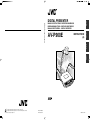
1
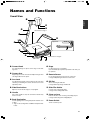
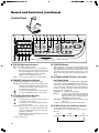
AV-P960E
INSTRUCTIONS
(A)
Français
MANUEL D’INSTRUCTIONS: PRESENTOIR NUMERIQUE
BEDIENUNGSANLEITUNG : DIGITALEN VORFÜHRERS
MANUALE DI ISTRUZIONI : DIGITAL PRESENTER
Italiano
Deutsch
AV-P960E DIGITAL PRESENTER
English
DIGITAL PRESENTER
®
®
is a registered trademark owned by Victor Company of Japan, Ltd.
is a registered trademark in Japan, the U.S.A., the U.K. and many other countries.
© 2004 Victor Company of Japan, Ltd
®
Printed in Thailand
LWT0149-001B-H
LWT0149-001B-H
Safety Precautions
For Europe
䡵 Dimensioni (LHP) (apparecchio: mm)
IMPORTANT
WARNING:
The wires in this mains lead are coloured in accordance
with the following code:
GREEN - and - YELLOW:
EARTH
BLUE:
NEUTRAL
BROWN:
LIVE
As the colours of the wires in the mains lead of this apparatus may not correspond with the coloured markings identifying the terminals in your plug, proceed as follows. The
wire which is coloured GREEN-AND-YELLOW must be connected to the terminal in the plug which is marked with the
letter E or the safety earth symbol
or coloured GREEN
or GREEN-AND-YELLOW. The wire which is coloured BLUE
must be connected to the terminal which is marked with
the letter N or which is coloured BLACK. The wire which is
coloured BROWN must be connected to the terminal which
is marked with the letter L or coloured RED.
TO PREVENT FIRE OR SHOCK HAZARDS, DO NOT EXPOSE THIS APPLIANCE TO RAIN OR MOISTURE.
Warning
Machine noise information regulation 3. GSGV, 18.01.1991:
The highest sound pressure level amounts to 70 railway
(A) less or in accordance with ISO/EN 7779
378
This is a Class A product. In a domestic environment this product may cause radio interference in which case the user may be required to take adequate measures.
495 (chiuso)
Thank you for purchasing this JVC product. Before operating this unit, please read these instructions carefully to ensure the best
possible performance.
These instructions are for AV-P960E.
Smooth, High Resolution Images
Built-in SD Card Slot
XGA output with high frame rate of 20 fps enabling
smooth high resolution image display.
Built-in high capacity, high speed SD card compatible
memory slot. (SD Card is sold separately.)
High Definition and High Power Zoom
Versatile Interface
Built-in 12x Optical Zoom Lens and 4x Digital Zoom.
Equipped with USB and RS-232 connector.
190 (chiuso)
Features
Italiano
653 (aperto formato A3)
WARNING–THIS APPARATUS
MUST BE EARTHED
491 (aperto)
I dati tecnici e il design di questo apparecchio sono soggetti a modifiche e miglioramenti senza preavviso.
Small, Lightweight and Slim Design
Depth of less than 50 cm and lightweight at below 6
kg, yet equipped with a field angle equivalent to A3
landscape (376 mm x 282 mm).
E-2
I-27
Table of Content
Safety Precautions .................................................................... 2
Features ..................................................................................... 2
Getting Started
Precautions ................................................................................ 4
Names and Functions ............................................................... 5
Overall View ....................................................................................... 5
Control Panel ..................................................................................... 6
Rear Panel .......................................................................................... 8
Preparation
Before Using .............................................................................. 9
Connection .............................................................................. 10
Presenting Printed Materials .................................................. 11
Presenting 3-dimensional Objects ........................................ 12
Shooting Surrounding Objects .............................................. 13
Operation
(Basic)
Presenting Slide Films ............................................................ 14
Presenting Films and Other Transparent Materials ............. 15
Capturing Images Through a Microscope ............................. 16
Saving Images in the Picture Memory .................................. 17
Adjusting the White Balance .................................................. 18
Saving the Settings (User Setting Registration) .................. 19
Operation
(Application)
Storing Images in SD Card ..................................................... 20
Viewing Image Data Stored in SD Card ................................. 21
Connecting to Computer via the USB Connector ................ 22
Operating the Remote Control Unit ....................................... 23
Others
Installing LCD Monitor ............................................................ 24
Troubleshooting ...................................................................... 25
Specifications .......................................................................... 26
How to Read this Manual
䡵 Symbols used in this manual
Caution
Note
☞
States precautions to be taken during operations.
States restrictions on the functions or use of this equipment. For reference purposes.
Indicates the page numbers or items to refer to.
䡵 Contents of this manual
● The copyright of this manual belongs to JVC. Unauthorized reproduction of this manual whether in full or in part is
prohibited.
● All product names stated in this manual are trademarks or registered trademarks of their respective companies.
Marks such as ™, ® and © are omitted in this manual.
● The design, specifications and other contents of this manual are subject to change for improvements without prior
notice.
● Windows is the trademark of Microsoft Corporation in the United States.
: SD logo is a trademark.
●
E-3
English
Table of Content ........................................................................ 3
Precautions
䡵 Handling of Equipment
● Use the handle on the side to carry this unit.
Carrying this unit by its camera head, camera arm or its side illumination lamps might cause them to be deformed or damaged.
● Pull out the handle slowly in a straight manner.
䡵 Conduct prior functional checks before important shooting events.
䡵 Compensation for the shooting contents
● JVC will not be in anyway liable for any failure to take or playback images due to problems arising from this product or the card
used, and no compensation will be offered for the loss of contents.
䡵 Copyright
● You may take pictures for your own leisure or uses. However, you must not use any materials protected by copyright law
without the owner's consent.
䡵 SD Card
SD card is made from precision electronic components. Do not attempt to carry out any of the following actions as it may cause
the card to malfunction or damage.
● Do not touch the edge of the card with your bare hand or metal.
It may be damaged by static charges produced.
● Do not bend, drop or cause the card to suffer great impacts.
● When using and storing the card, avoid heat, water, direct sunlight and humid areas.
● Do not attempt to disassemble or modify the card.
䡵 Routine maintenance
Switch off the power, pull out the plug and perform the following tasks.
● Use a dry and soft piece of cloth to wipe off any dirt or stain on the equipment.
● For severe stains, immerse a piece of cloth into a diluted cleaning detergent, wring and use it to wipe off the stains on the
equipment. Thereafter, use a piece of dry cloth to wipe off the water drops.
Caution
● Do not use benzene or thinner. The equipment may malfunction and its casing may be damaged.
● When using a chemical wrap or detergent, read its product brochures carefully and take note of any precautions
stated.
䡵 Auto Focus
This unit is equipped with Auto Focus function. However, depending on the object and the camera setting, it might be out of
focus. In this case, please adjust the focus manually.
Objects which are difficult to be focused automatically
●
●
●
●
●
●
When the brightness of the image plane is extremely high (bright).
When the brightness of the image plane is extremely low (dim).
When the brightness of the image plane is constantly changing (for example, a blinking light).
When there is almost no contrasts.
When there are repetitive vertical striped patterns on the image plane.
When there are graphics or printings on both sides or the upper and lower portions of the screen.
䡵 Power Cord
● Use only the power cord specified (supplied).
Use of power cord other than designated, or damaged power cord may result in fire and electrical shocks.
● Do not use the power cord supplied with this unit on other devices.
䡵 Power Saving
To save power, turn off the unit when not in use.
E-4
Names and Functions
Overall View
English
1
0
!
2
Rear Panel ☞ Page 7
3
4
4
Right Side
@
5
6
7
Control Panel ☞ Page 6
8
1 Camera Head
For capturing images of objects on the stage or surrounding areas.
2 Camera Arm
Supporting arm for the camera head. Adjust its angle when
shooting 3-dimensional objects.
3 Arm Lock
For adjusting the length of camera. Release the lock when
retracting or extending the camera arm and lock it at the
adjusted position.
4 Side Illuminations
Adjust to ensure that the stage is evenly lighted.
5 Handle
Pull out this handle to carry the unit. Put the handle away
when not in use.
6 Back Illumination
Use this lighting when viewing transparent materials such
as films.
☞ Page 15 ‘Presenting Films and Other Transparent Materials’
9
7 Stage
For placing objects (or materials).
Up to A3 landscape equivalent (376 mm x 282 mm) can
be captured.
8 Remote Sensor
For receiving signals from the remote control unit.
☞ Page 23 ‘Operating the Remote Control Unit’
9 SD Slot
Slot for inserting the SD card.
☞ Page 20 ‘Storing Images in SD Card’
0 Slide Film Holder
Use this when viewing slide films.
☞ Page 14 ‘Presenting Slide Films’
! Close-up Lens
Remove this lens when shooting surrounding objects.
☞ Page 13 ‘Shooting Surrounding Objects’
@ Power Switch
To turn on/off the power.
E-5
Names and Functions (continued)
Control Panel
#
@
!
0
9
8 7
6 5
4 3
2
1
USER SETUP
DEFAULT
USER
SAVE
DELETE
WHITE BALANCE
AUTO
CAMERA
RED
PICTURE MEMORY
1
2
3
PAGE
NEGA POSI BW COLOUR
SAVE
LIGHT
TEXT
IMAGE SELECT
ENTER
SD CARD
%
^
&
BRIGHT
CAMERA
AUTO
FOCUS
ZOOM
EXT IN
OUT
IN
SOURCE SELECT
*
1 [ZOOM] Adjustment Buttons
Adjust in accordance with the object.
[IN]
: To shoot objects (materials) in an enlarged form.
If this button is pressed continuously, the image
will stop enlarging at the optical zoom tele end
and thereafter digital zoom will be activated.
(Optical zoom: 12x, Digital zoom: 4x)
[OUT] : To shoot objects (materials) in a reduced form.
2 [BRIGHT] Adjustment Buttons
For adjusting the brightness of the camera image.
[AUTO] : When this button is pressed, the indicator lamp
will blink and the brightness will be adjusted automatically. The indicator lamp will go off once
the adjustment is completed.
[ ]
: To increase the brightness of the camera image.
[ ]
: To reduce the brightness of the camera image.
3 [FOCUS] Adjustment Buttons
For adjusting the focus of the camera.
[ ]
: To adjust the focus of the object (material) which
is far away from the camera.
[ ]
: To adjust the focus of the object (material) which
is close to the camera.
[AUTO] : When this button is pressed, the indicator lamp
will blink and the focus will be adjusted automatically. The indicator lamp will go off once the adjustment is completed.
Depending on the object (material), it may be difficult to adjust the focus.
☞ Page 4 ‘Auto Focus’
E-6
AUTO
MICROSCOPE
SD CARD SYSTEM
$
FREEZE
BLUE
4 [FREEZE] Button
When this button is pressed, the camera image freezes
and is displayed as a still image, and the indicator lamp
lights up. When the button is pressed again while the indicator lamp is light up, the indicator lamp will go off, still
image will be released and the moving image will be restored.
5 [SOURCE SELECT] Buttons for Selecting Output Image
To select the image to be outputted from the [RGB OUTPUT] terminal and the [MONITOR OUTPUT] terminal located at the rear panel. The indicator lamp of the input
source selected for outputting will light up. Depending on
the types of monitor connected , it may take some times
for the images to be displayed.
[CAMERA] : To output the camera images.
[EXT IN]
: To output signals inputted to the [EXT INT]
terminal located at the rear panel. External
input signals will not be output through the
[MONITOR OUTPUT] terminal.
[SD CARD] : To output images from the SD card inserted
in the slot.
☞ Page 21 ‘Viewing Image Data Stored in SD Card’
6 [LIGHT] Button for Switching Lighting
To switch between different lighting sources.
The lighting source changes whenever the button is
pressed.
Side
illuminations
Back
illumination
All
illuminations off
7 ~ 0 are functional only if SD card is inserted into the SD
Slot.
7 [IMAGE SELECT/ENTER] Button for
Selecting Images
Displays the miniature images of the SD card in a view of
16.
☞ Page 21 ‘Viewing Image Data Stored in SD Card’
8 [SAVE] Button for Saving SD Card
While selecting images from the camera, if this button is
pressed for more than 2 seconds, the indicator lamp will
blink and the image currently displayed will be stored in
the SD card.
☞ Page 20 ‘Storing Images in SD Card’
9 [PAGE] Buttons
To select and display images stored in the SD card.
[ ]
: To view the previous image.
[ ]
: To view the next image.
0 [DELETE] Button for Deleting SD Card
To delete selected images stored in the SD card.
When the [SD CARD] has been selected by the [SOURCE
SELECT] button 5, pressing this button for more than 2
seconds, the indicator lamp will blink and the selected image will be deleted.
☞ Page 20 ‘Deleting images’
! [PICTURE MEMORY] Buttons
To store the output image in the internal picture memory
or to select and display the images stored in the picture
memory.
[1] ~ [3]
: Press the button for more than 2 seconds,
the button indicator lamp # will blink and the
image will be stored in the picture memory.
Press this button to output the stored image.
[CAMERA] : To select the camera image.
☞ Page 17 ‘Saving Images in the Picture Memory’
@ [USER SETUP] Buttons for Setting
Registration
To perform settings related to value setting.
[SAVE]
: The present user settings will be registered.
[USER]
: The registered settings will be activated.
[DEFAULT] : Setting reverts back to default (factory) setting.
☞ Page 19 ‘Saving the settings (User Setting Registration)’
# Button Indicator Lamps
Indicator lamps will blink when button ! ~ * has been
operated and the various settings are in the process of
being changed.
$ [WHITE BALANCE] Adjustment Buttons
To perform settings related to white balance.
[AUTO]
: If this button is pressed, the indicator lamp
will blink while the white balance is being readjusted.
[RED ] : Increase the red component of the entire
screen.
[RED ] : Decrease the red component of the entire
screen.
[BLUE ] : Increase the blue component of the entire
screen.
[BLUE ] : Decrease the blue component of the entire
screen.
☞ Page 18 ‘Adjusting White Balance’
% [NEGA/POSI] Button for Switching
between Negative/Positive Film
Set to Nega when viewing negative films.
Negative will be selected when the button is pressed.
Press the button again, positive will be selected.
☞ Page 15 ‘Presenting Films and Other Transparent Materials’
^ [BW/COLOUR] Button for Switching
between Black & White and Colour
To switch the output image between Black & White and
Colour display.
Black & White image will be selected when the button is
pressed. Press the button again, Colour image will be selected.
& [TEXT] Button
To make the character clearer and sharper.
Text mode will be activated when the button is pressed. To
deactivate, press the button again.
* [MICROSCOPE] Button
Press this button when capturing images from a microscope.
Once the button is pressed, the zoom and focus meant for
microscope will be set.
☞ Page 16 ‘Capturing Images Through a Microscope’
E-7
English
SD CARD SYSTEM
Names and Functions (continued)
Rear Panel
Refer to page 10 ‘Connection’ for details on connecting with other devices.
Caution
Do not open the cover at the bottom of the
arm and put your finger or insert object into
it. This may cause malfunction or injury.
1
AC IN
2 345
6 7
8
USB
MONITOR
OUTPUT
RGB OUTPUT
EXT INPUT
REMOTE INPUT
(RS-232C)
NTSC
1 [AC IN] Power Inlet
Connect using the power cord supplied to an AC 100 V ~
AC 240 V power source.
2 [MONITOR OUTPUT] Terminal
Image signal output terminal for confirming viewing angle.
PAL
5 [EXT INPUT] Terminal for External Signal Input
For connecting to external devices such as computer. When
using the [SOURCE SELECT] button to select the external
input, the signals will be output through the [RGB OUTPUT]
terminal. In this case, output through the [MONITOR OUTPUT] terminal is not possible.
3 [RGB OUTPUT] Terminal
RGB signal output terminal. Connect to the RGB input terminal of a projector or monitor.
4 [USB] Connector
For connecting to devices such as computer. Image data
or image memory stored in the SD card as well as image
data stored in this unit can be downloaded to the computer.
☞ Page 22 ‘Connecting to Computer via the USB Connector’
6 LCD Monitor Mounting Screw Hole
Use when mounting the LCD Monitor (sold separately) to
this unit.
☞ Page 24 ‘Installing LCD Monitor’
7 [REMOTE INPUT (RS-232C)] Terminal
Connect when controlling this unit via the PC using the
control software created by customer. For communication
method and command, read [RS-232C External control
communication commands (command. pdf)] in the provided
CD-ROM.
8 [NTSC/PAL] Switch
Set according to the monitor to be used.
E-8
Before Using
Install according to the following steps.
Right Illumination
Left Illumination
1.
Lift up the right illumination
2.
Lift up the left illumination
3.
Lift up the camera head (camera arm)
English
1.
2.
Hold the camera arm and hold down the unit firmly while slowly
lifting the camera head until it reaches its maximum position and
stops.
4.
Camera Head
4.
Releasing the arm lock
Pull the lever of the arm lock in the direction of the arrow as
shown in the figure to release the lock.
Camera Arm
Arm
Lock
3.
5.
Extending the camera arm
Hold down the lower portion of the camera arm or the unit firmly
while holding the upper portion of the camera arm and slowly extend
the camera arm until it reaches its maximum position and stops.
6.
Return the lever of the arm lock in the direction of the arrow to
lock the arm.
5.
7.
6.
Camera Arm
Securing the camera arm
Arm
Lock
7.
Turn the camera head towards the
stage
Carry out the reverse steps to fold up.
Stage
If the steps are carried out wrongly, the camera head and arm may
be damaged.
Caution
● When retracting the camera arm, do not hold the connecting
portion of the camera arm with your hand. It might get caught
resulting in injury.
Caution
● Do not try to retract or extend the camera arm when it has been
folded forward.
The interior of the camera arm may be damaged if excessive force is
applied.
Make sure that the camera head (camera arm) has been lifted up as
described in Step 3. before retracting or extending the camera arm.
● Do not hold the camera head when lifting, folding, retracting or
extending the camera arm.
The camera head and the interior of camera arm may be damaged if
excessive force is applied. Make sure to hold the camera arm when
performing steps 3. and 5..
E-9
Connection
Install according to the following steps. The [MONITOR OUTPUT] terminal is use to confirm the images.
LCD Monitor
Computer
2.
[MONITOR OUT]
[RGB
OUT]
5.
3. [USB]
Terminal
Power Switch
USB Terminal
Projector
Left Illumination
[AC IN]
4.
1.
(supplied power cord)
AC Power
The LCD monitor, computer and projector are sold separately.
1.
Connect the [RGB OUTPUT] terminal
to a projector or display.
● The output of this unit is XGA, connect it to a compatible device.
● Commercially available D-sub 15 pin cable (below 3 m) is recommended.
2.
If necessary, connect the [MONITOR
OUTPUT] terminal to a monitor etc.
3.
If necessary, connect the USB connector to a computer.
☞ Page 22 ‘Connecting to Computer via the USB Connector’
E-10
4.
Connect to the AC power source with
the power cord supplied.
5.
Turn on the power.
Presenting Printed Materials
Camera Head
1.
Arm
1.
1.
Adjusting the arm and camera head
Adjust the arm and camera head in accordance with the size of
the object.
2.
● Ensure that the camera head is positioned at the centre of the
object.
2.
● The arm is catered to capture an A3 landscape equivalent object
when fully extended.
[BRIGHT] button
[ZOOM]
button
2.
Adjusting lighting
Adjust such that the object is evenly lighted.
[FOCUS] button
3.
Adjusting zoom
Adjust such that the portion of the object to
be captured occupies the full screen.
ZOOM
OUT
(Example) Too little zooming.
4.
IN
Adjusting brightness
AUTO
BRIGHT
Adjust when the screen is too bright or too
dim.
Press the [AUTO] button and the appropriate brightness will be adjusted automatically.
(Example) Poor lighting.
5.
Adjusting focus
AUTO
FOCUS
To adjust the focus when it is out.
Press the [AUTO] button and the focus will
be adjusted automatically.
(Example) Focus is out.
Note
● For materials with a mixture of portrait and landscape printed
materials, it may be more convenient to save either one of the
orientations under the user setting. (☞ Page 19 ‘Saving the Settings (User Setting Registration)’)
(Example) Correctly adjusted.
E-11
English
Up to A3 landscape equivalent (376 mm x 282 mm) printed materials can be captured.
Presenting 3-dimensional Objects
3-D object placed on the stage can be captured. In addition, by adjusting the angle of the arm, the 3-D object can be captured at
various angles.
1.
1.
Adjusting the arm and camera head
Adjust the arm and camera head in accordance with the size of
the object.
● Ensure that the camera head is positioned at the centre of the
object.
● The arm is catered to capture an A3 landscape equivalent object when fully extended.
2.
2.
2.
Adjusting lighting
Adjust such that the portion of the object to be captured is evenly
lighted.
3.
Adjusting zoom
ZOOM
OUT
4.
Adjust such that the portion of the object to
be captured occupies the full screen.
IN
Adjusting brightness
AUTO
BRIGHT
Adjust when the screen is too bright or too
dim.
Press the [AUTO] button and the appropriate brightness will be adjusted automatically.
6.
5.
Adjusting focus
AUTO
FOCUS
To adjust the focus when it is out.
Press the [AUTO] button and the focus will
be adjusted automatically.
6.
Tilt the arm at an angle to capture
Note
● 3-D objects if taken from a slanting angle provides realistic
images.
E-12
Shooting Surrounding Objects
Camera Head
1.
Turn the camera head towards the
object
2.
Remove the close-up lens
English
The camera head can be turned to shoot the surrounding objects.
1.
Press and hold the claws while pulling out the lens.
3.
Adjusting the image
Adjust the zoom, brightness and focus.
2.
Close-up lens
3.
[BRIGHT] button
[ZOOM]
button
[FOCUS]
button
E-13
Presenting Slide Films
Slide films with frame can be inserted directly into the camera head for presentation.
1.
Place a piece of white paper on the
stage
As the slide film makes use of the reflecting light from the stage
surface, place a highly reflective white paper (B4 size or A3 size)
on the stage.
2.
2.
1. [BRIGHT] button 2.
Adjusting side illuminations
Adjust such that the stage surface is evenly lighted.
te
Whi er
pap
[ZOOM]
button
3.
Stage
Insert the slide film
Note
Use only slide films with mounting frame.
4.
3.
Adjusting zoom
ZOOM
OUT
5.
Adjust such that the portion of the object to
be captured occupies the full screen.
IN
Adjusting brightness
AUTO
Adjust the brightness while looking at the
image displayed on the monitor.
BRIGHT
Notes
5. [BRIGHT] button
4.
[ZOOM]
button
6. [FOCUS]
button
● Automatic brightness adjustment will be disabled whenever
Nega is selected. The indicator lamp blinks rapidly to indicate
that operation is not possible.
● Under negative mode, pressing the [BRIGHT ] button dims
the images while pressing the [BRIGHT ] button brightens
the images.
● Under negative mode, pressing the [WHITE BALANCE] buttons [RED ] or [BLUE ] decreases the red or blue component while pressing the [RED ] or [BLUE ] button increases
the red or blue component.
6.
Adjust focus
Use the [FOCUS
,
] buttons to adjust the focus.
Note
If the slide film is inserted vertically, zooming in (enlarging) until the mounting frame cannot be seen may cause the focus to
be out. In this case, set zoom to [OUT].
E-14
Presenting Films and Other Transparent Materials
Films can be placed on the stage for presentation.
Press the [LIGHT] button to turn on
the back illumination
English
1.
The lighting source changes whenever the [LIGHT] button is
pressed.
Side
illuminations
Back
illumination
2.
Back
illumination
All
illuminations off
Place the films and other transparent
materials on the stage
Place the film at the centre of the stage and adjust the camera
head directly on top of the film.
1. [LIGHT]
button
3.
Setting Nega/Posi
In the case of a negative film, press the [NEGA/POSI] button to
set to negative mode.
4.
Adjusting zoom
ZOOM
OUT
5.
5.
3.
IN
Adjusting brightness
AUTO
6. 4.
Adjust such that the portion of the object to
be captured occupies the full screen.
Adjust the brightness while looking at the
image displayed on the monitor.
BRIGHT
Notes
● Automatic brightness adjustment will be disabled whenever
Nega is selected. The indicator lamp blinks rapidly to indicate
that operation is not possible.
● Under negative mode, pressing the [BRIGHT ] button dims
the images while pressing the [BRIGHT ] button brightens
the images.
● Under negative mode, pressing the [WHITE BALANCE] buttons [RED ] or [BLUE ] decreases the red or blue component while pressing the [RED ] or [BLUE ] button increases
the red or blue component.
6.
Adjust focus
Use the [FOCUS
,
] buttons to adjust the focus.
E-15
Capturing Images Through a Microscope
Images from the microscope can be captured by aligning the view piece of the microscope with the camera head.
The procedures described below are for using the adaptable microscope ECLIPSE E200 from Nikon.
4.
1.
3.
Setting the microscope
● Prepare the microscope, such as focus adjustment, for viewing.
● For the usage of the microscope, refer to the instruction manual
of the microscope.
2.
Place the microscope on a platform of
about 10 cm high
3.
Remove the close-up lens
4.
Adjust the position of the camera
head
2.
USER SETUP
DEFAULT
USER
SAVE
WHITE BALANCE
AUTO
CAMERA
RED
BLUE
PICTURE MEMORY
1
2
NEGA POSI BW COLOUR
TEXT
3
Adjust the camera head and the view piece of the microscope such
that their respective centre are aligned.
● Adjust the length and angle of the arm.
● Adjust the angle of camera head.
MICROSCOPE
5.
5.
Press the [MICROSCOPE] button
6.
Adjusting the image
● Adjust the brightness and focus while confirming the images.
E-16
Saving Images in the Picture Memory
Frequently used images can be saved in the picture memory of this unit. Switching between camera images and images from the
picture memory is possible while presentation is in progress. Up to 3 images can be saved.
Press the [CAMERA] button
English
1.
The camera image is outputted.
[BRIGHT]
button
Button
Indicator
Lamp
[ZOOM]
[FOCUS] button
button
2.
Adjusting zoom
3.
Adjusting brightness
4.
Adjusting focus
5.
Press [PICTURE MEMORY 1] button for
more than 2 seconds
USER SETUP
DEFAULT
USER
SAVE
● The button indicator lamp will light up initially before blinking. It
will go off once the image has been saved.
● The image will become still image.
WHITE BALANCE
AUTO
CAMERA
RED
BLUE
PICTURE MEMORY
1
2
NEGA POSI BW COLOUR
TEXT
3
6.
MICROSCOPE
Repeat Steps 1. ~ 5.
Perform the same procedures for picture memory 2 and 3.
1.
5.
䡵 Retrieving Stored Images
1.
Press the [PICTURE MEMORY] button
The stored images in this unit will be displayed.
Note
● When retrieving the images stored in this unit, do not press
the [PICTURE MEMORY] buttons for more than 2 seconds. The
image will be stored.
● If no image is stored in the picture memory, the screen will
turn black and nothing will be displayed when the [PICTURE
MEMORY] button is pressed.
Notes
● This unit is designed to display A4 portrait in full with the camera arm fully extended. For materials with a mixture
of portrait and landscape pages, it may be convenient to save either one of the orientations in the picture memory
before presenting.
● Contents of the picture memory are lost if the power is turned off.
● Existing images stored in the picture memory will be overwrite whenever new images are being stored.
● SD images cannot be stored in this unit.
E-17
Adjusting the White Balance
䡵 Adjusting the White Balance Automatically
This unit is adjusted to display the natural colour. However, the white balance can be re-adjusted with the following steps.
1.
Place a piece of white paper on the
stage
2.
Adjusting zoom
Adjust till the full screen becomes white.
White paper
3.
Adjusting brightness
4.
Press the [WHITE BALANCE AUTO]
button
The white balance will be re-adjusted in about 5 seconds.
● The button indicator lamp will blink initially, and goes off once
the white balance adjustment has been completed.
[WHITE BALANCE
AUTO] button
䡵 Adjusting the White Balance Manually
Depending on the object, if the images appear reddish, bluish or the overall colour tone appears to be bad even after the
automatic white balance adjustment has been performed, adjust the colour balance manually.
RED
Increase the red
component
Decrease the red
component
BLUE
Increase the blue
component
Decrease the blue
component
USER SETUP
DEFAULT
USER
SAVE
WHITE BALANCE
AUTO
CAMERA
RED
PICTURE MEMORY
1
2
NEGA POSI BW COLOUR
E-18
BLUE
TEXT
3
MICROSCOPE
Saving the Settings (User Setting Registration)
䡵 Registration
1.
Adjusting the camera
● Adjust the camera to the settings to be registered.
● The following user settings are possible. ( ) are factory settings.
• Zoom position (Approximately A4 portrait position)
• Lighting status (Both side illuminations light up)
• White Balance (Value corresponding to side illumination)
• Nega/Posi (Posi)
• Black & White/Colour (Colour)
• Text (OFF)
2.
Button Indicator
Lamp
● The button indicator lamp will light up initially before blinking. It
will go off once the writing process has been completed.
● The written settings will be retained even if the power is turned
off.
USER SETUP
DEFAULT
USER
SAVE
WHITE BALANCE
AUTO
CAMERA
RED
BLUE
PICTURE MEMORY
1
2
NEGA POSI BW COLOUR
Press the [SAVE] button for more than
2 seconds
TEXT
3
MICROSCOPE
䡵 Recalling the settings
1.
Press the [USER] button
● The registered settings will be activated.
䡵 Undo the settings
(Restoring the factory settings)
1.
Press the [DEFAULT] button
● The factory settings will be restored.
2.
Press the [SAVE] button for more than
2 seconds
● The button indicator lamp will light up initially before blinking. It
will go off once the writing process has been completed.
E-19
English
The recalled settings upon power up or when the [USER] button is pressed can be registered.
Storing Images in SD Card
Images taken can be stored in the SD card (sold separately).
1.
Press the [CAMERA] button
2.
Insert the SD card
● To remove the SD card, push in the card before removing it from
the card slot.
1.
3.
● The save indicator lamp lights up ➞ Blinks while saving is in
progress. Blinks ➞ Lights up ➞ Light goes off once saving is
completed. (about 2 seconds)
● Saving is not possible if the SD card switch has been turned on
to write-protect. In this case, the save indicator lamp will not blink.
● If the SD card is full and additional images cannot be stored, the
save indicator lamp will not blink. In this case, delete unwanted
images or use a new card.
2.
DELETE
SAVE
3.
PAGE
Press the [SAVE] button for more than
2 seconds
IMAGE SELECT
ENTER
SD CARD SYSTEM
䡵 Deleting images
1.
Select the image to delete
● <Normal screen>
To delete image, use the [PAGE
image to be deleted.
,
] buttons to select the
● <Thumbnail screen>
When the thumbnail screen is being displayed, use the [PAGE
, ] buttons to move the cursor to select the image to be
deleted.
Notes
● If an image is deleted in the thumbnail screen,
the next image will shift up and be displayed
in its position.
● The cursor will move to the next image following the deleted image.
2.
Press the [DELETE] button for more
than 2 seconds
● The delete indicator lamp lights up ➞ Blinks while deleting is in
progress. Blinks ➞ Lights up ➞ Light goes off once deleting process is completed. (about 2 seconds)
Notes
● When removing or inserting the SD card or when powering off, make sure to press the [CAMERA] button and
confirm that the output image is a camera image. Otherwise, the data in the card may be corrupted or this unit may
not function properly.
● The SD card is made from parts that are susceptible to static charges. Malfunction might occur and the contents of
the card might be damaged due to static charges. As such, make sure to handle with extra care.
● Do not leave the SD card in the card slot. Remove the SD card for safe keeping after use.
● Number of images that can be stored:
32 MB: about 60 images, 64 MB: about 120 images
● 32 MB or 64 MB SD card from Panasonic is recommended.
E-20
Viewing Image Data Stored in SD Card
5.
1.
1.
2.
3.
Insert the SD card
Press the [SD CARD SYSTEM] buttons
Viewing images
<Viewing images one at a time>
DELETE
SAVE
PAGE
IMAGE SELECT
ENTER
SD CARD
Press the [PAGE] buttons
FREEZE
LIGHT
EXT IN
● The image switches whenever the button is pressed.
● The image will switch continuously if the button is pressed and
held. (at an interval of about 0.5 seconds)
CAMERA
Note
SD CARD SYSTEM
3.
SOURCE SELECT
● The first image of the SD card will be displayed if the [IMAGE SELECT/ENTER] button is pressed for more than 2 seconds.
3. 2.,3. 4.
<Viewing images at one time (thumbnail)>
Press the [IMAGE SELECT/ENTER] button
● 16 images are displayed in a view.
● Use the [PAGE , ] buttons to move the cursor.
● Pressing [ ] at the last image of the page displays the next
page while pressing [ ] at the first image of the page displays
the previous page.
● If the [IMAGE SELECT/ENTER] button is pressed when the
image has been selected by the cursor, the selected image
will be displayed on the screen in full size.
<Thumbnail display screen>
● The cursor will move as shown below when the
[PAGE ] button is pressed.
<Viewing images one at a time automatically (slide show)>
While holding down the [SD CARD SYSTEM] buttons, press
the [IMAGE SELECT/ENTER] buttons within 1 second.
● From the image currently displayed, the following images will
be displayed in sequence automatically. (at an interval of about
2 seconds)
● When the [IMAGE SELECT/ENTER] or [PAGE] buttons are
pressed once again, the image being played back will be selected and the operation stops.
Next page
Cursor
● Pressing and holding either the [ ] or [ ] button moves the cursor continuously (at an interval of 0.1 second). If the last image of the current page is reached, the next page will be displayed.
● The image selected by the cursor can be deleted. (☞ Page 20 ‘Deleting images’)
4.
Press the [CAMERA] button
● Confirm that the output image is a camera image.
5.
Removing the SD card
● To remove the SD card, push in the card before removing it from
the card slot.
Notes
● When removing or inserting the SD card or when powering off, make sure to press the [CAMERA] button and confirm that the output image is a
camera image. Otherwise, the data in the card may be corrupted or this unit may not function properly.
● The SD card is made from parts that are susceptible to static charges. Malfunction might occur and the contents of the card might be damaged
due to static charges. As such, make sure to handle with extra care.
● Only images that are of the same type as the data stored via this unit can be viewed.
● JPEG data taken with digital camera and JPEG data downloaded via Web may be converted to image data viewable on this unit by using [JPEG
conversion software (Exif Conv.exe)] in the CD-ROM provided with this unit. For details, read JPEG conversion software’s Instruction [Exif
Cnv.pdf] in the CD-ROM.
(The software [JPEG conversion software (Exif Conv.exe)] can also be downloaded from http://www.jvc-victor.co.jp/english/pro/prodv/download/index.html.)
● If SD card image is selected without inserting the card, the output image will turn black.
● The zoom, brightness and focus operations are not applicable for images stored in the SD card.
E-21
English
Images stored in the SD card can be viewed.
Connecting to Computer via the USB Connector
By connecting to the computer, image data or image memory stored in the SD card as well as image data stored in this unit can be
downloaded to the computer.
䡵 Compatible Computers
OS: Windows姞 Me/2000/XP
䡵 When connecting for the first time
With the Windows’ plug and play capability, the necessary driver will be
installed automatically for this unit to be recognized by the computer.
Install according to the instructions displayed on the screen. (These
instructions will not be shown when the computer is connected again
subsequently.)
䡵 Operating Methods
1.
Turn on the power
Turn on the power of this unit and the computer.
2.
● Pull out and insert the cable slowly and securely.
USB Cable
3.
Caution
<When SD card is inserted>
● The image data stored in the SD card will be displayed.
···
“My Computer”
“Removable Disk”
“DCIM”
“100JVCAV”
“IMAG0001.JPG”
“IMAG0002.JPG”
<When SD card is not inserted>
● The image data stored in this unit will be displayed.
(Picture memory 1~3, still image)
“My Computer”
“Removable Disk”
“DCIM”
“100JVCAV”
“MEMORY1.JPG”
“MEMORY2.JPG”
“MEMORY3.JPG”
“STILL.JPG”
4.
Example) When using Windows XP
Click according to the following sequence: “Start” ➞ “My Computer” ➞
“Removable Disk”
E-22
Confirming the image data
The image data will be stored as JPEG images in the folder
“100JVCAV”. When the USB cable is connected as in step 2, the
display on the screen varies as follows, depending on whether the
SD card is inserted or not.
● Formatting or writing of data into the SD card from the
computer through this unit is not possible.
● As this unit is not equipped with clock function, the date
and time of all the image files created will be 0.00 am,
January 1, 2003.
● When USB cable is connected, even if the SD card is removed and inserted again, the image data on the computer
screen remain unchanged. To change the display, disconnect the USB cable, remove and insert the SD card before
reconnecting the USB cable. In addition, the display on the
computer screen can also be switched with the USB cable
remain connected using the following methods:
• While holding down the [SD CARD] button, press the
[DEFAULT] button within 1 second.
¥ The display when SD card is inserted will be displayed on the computer screen.
• While holding down the [CAMERA] button, press the
[DEFAULT] button within 1 second.
¥ The display of picture memory in this unit will be
displayed on the computer screen.
● Do not remove or insert the USB or switch the image
data display on the computer screen while the buttons,
the remote control unit or the computer is being operated. This might cause malfunction such as warnings
appearing on the computer screen.
Note
Connect using the USB cable
Downloading the image data
Use the viewer software on the computer to confirm the image
data before downloading to the computer.
Refer to instruction manual of the computer for the downloading
method.
Operating the Remote Control Unit
The following functions are available with the use of the remote control unit.
1 2 3
English
1 [CAMERA]
To output the camera images.
(☞ Page 6 5 [SOURCE SELECT] Buttons)
2 [FREEZE]
CAMERA
FREEZE
IMAGE SEL.
SD CARD
8
AUTO
BRIGHT
AUTO
FOCUS
AUTO
WHITE
To make the camera image still.
(☞ Page 6 4 [FREEZE] Button)
EXT-IN
OUT
IN
ZOOM
4
5
6
7
3 [EXT-IN]
The images of the device connected to the [EXT INPUT] terminal
will be outputted.
(☞ Page 6 5 [SOURCE SELECT] Buttons)
4 [SD CARD]
To perform functions related to SD card.
● While displaying images from other sources, SD selection mode
will be activated if this button is pressed.
(☞ Page 6 5 [SOURCE SELECT] Buttons)
5 [BRIGHT]
To adjust the brightness of the camera image.
(☞ Page 6 2 [BRIGHT] Adjustment Buttons)
6 [FOCUS]
To adjust the focus of the camera image.
(☞ Page 6 3 [FOCUS] Button)
7 [ZOOM]
To reduce or enlarge the camera image.
(☞ Page 6 1 [ZOOM] Adjustment Buttons)
8 [AUTO WHITE]
To adjust the white balance automatically.
(☞ Page 7 $ [WHITE BALANCE] Adjustment Buttons)
*For details on the various functions, refer to page 6.
䡵 Remote control receiving range
The receiving range is about 5m.
The vertical plane is ± 15˚ and the horizontal plane is ± 30˚.
Up down ± 15˚
Left right ± 30˚
5m
E-23
Installing LCD Monitor
Connect commercially available LCD monitor to the [MONITOR OUTPUT] terminal. It is convenient for adjusting viewing angle.
1.
Mount the LCD monitor mounting
bracket (AV-ZK10, sold separately) to
the LCD monitor using the screw supplied with the bracket.
2.
Mount the LCD monitor mounting
bracket (AV-ZK10, sold separately) to
this unit using the screw supplied with
the bracket.
3.
Connect the LCD monitor to the
[MONITOR OUTPUT] terminal of this
unit with a video cable
4.
Turn on the power of the LCD monitor
LCD monitor
1.
2.
Screw for
adjusting angle
LCD monitor-mounting
bracket
(AV-ZK10, sold separately)
(Refer to the instruction manual of the LCD monitor used for details.)
5.
E-24
Adjust the angle adjusting screw for
the best viewing angle
Troubleshooting
When you encounter a problem, check the following points for a solution. If the problem persists, stop using this unit and consult
your nearest JVC dealer.
No image appears.
Focusing is not possible.
Verify the following points
●
●
●
●
●
Is the power plug connected to an AC outlet?
Is the power switch turned on?
Is this unit connected correctly to the projector or display?
Is the brightness set to the optimum level?
Are you sure that the pictures have been stored to memory? First store the
pictures to memory and then recall them.
● Is [EXT IN] or [SD CARD] of [SOURCE SELECTION] being selected? Select
[CAMERA].
● Is a XGA compatible projector or display used?
● Is the close-up lens attached?
● Is the object too close to the lens or is the top of the object at a height of more
than 50 mm from the stage surface?
● Did you shoot the surrounding objects with close-up lens attached? When shooting surrounding objects, remove the close-up lens.
● Did you enlarge the image size with the zoom after focusing was achieved?
Perform focusing after enlarging the image with zoom.
● With [FOCUS AUTO], focusing may be difficult depending on the object. Adjust
the focus using [FOCUS , ] buttons.
● If the unit is connected to the projector, make sure that the projector is focused
correctly. Refer to the projector's instruction manual for focusing procedure.
Refer to Page
10
10
6
17
6
10
5
13
6
The image is blurred.
Dust is visible.
● Is the close-up lens or camera lens dirty? Clean it with a commercially available cleaner.
The image is dark.
● Are the side illuminations lighted?
● Is the brightness set appropriately?
3
6
Stripe pattern appears on
the image of printed
material.
● Dots in the printed matter may interfere with the pixels in the camera image
device resulting in colour stripes. In this case, change the image size slightly
with the [ZOOM] buttons.
11
The colour tone doesn’t
seem right.
● Have you adjusted the tone with the [WHITE BALANCE]?
● Make sure that the negative mode is not engaged.
7
7
Beats appear in the image.
● When this unit is used near equipment generating a strong electric wave, beats
may occur in the image. Keep this unit away from such equipment.
The image flickers.
● In areas where the 50 Hz power frequency is used, flickering may occur on the
screen when a fluorescent light or mercury-vapour lamp is used. Use this unit
with the side illuminations lighted.
The image cannot be
adjusted.
● When the [FREEZE], [PICTURE MEMORY], [EXT IN] or [SD CARD] is selected, the camera image cannot be adjusted. Return to [CAMERA] image to
adjust.
● When brightness is insufficient, this unit may not work properly even if you
adjust the brightness. Press the [LIGHT] button to turn on the side illuminations.
This unit does not operate
even when the button is
pressed.
● When two buttons are pressed simultaneously, or a button is repeatedly pressed
without pauses, the unit may not operate correctly. When operating the buttons, do it one at a time with intervals between each press.
The remote control unit
does not work.
● Are there batteries in the remote control unit?
● Are the batteries exhausted?
The batteries provided are for operation check only. Install commercially available batteries for actual usage.
● Is the remote control unit being operated outside the effective range?
The camera image has
white or black spots.
English
Symptoms
6,7
7
11
23
● Black or white spots may occasionally appear due to the characteristics of the
high-pixel CCD for graphics. If the image is enlarged with the digital zoom
function, spots may be particularly noticeable.
E-25
Specifications
䡵 GENERAL
Power requirements
Current consumption
Mass
: AC 100 V to 240 V 50 Hz / 60 Hz
: 0.5 A
: 5.6 kg (12.3 lbs.)
䡵 OPTICAL
Lens
Shooting area
Focal distance adjustable range
Zoom
Focus
Brightness
: F1.8 to F2.8, f = 5.4 mm to 64.8 mm (12 times)
: Max.: 376 mm x 282 mm (14-4/5" x 11-1/10") (A3 landscape equivalent)
: From the stage surface to a height of 50 mm (1-31/32") from the stage surface (the camera
directed downward, with close-up lens)
∞ to 0.8 m (2.6 ft) (the camera directed to the side, without close-up lens)
: Optical zoom: 12x, Digital zoom: 4x
: Auto/manual
: Auto/manual
䡵 LIGHTING
Side illumination
Back illumination
: 6 W x 2 (inverter lighting)
: 4 W x 1 (inverter lighting, area size 127 mm x 100 mm (5" x 3-15/16"))
䡵 CAMERA HEAD
Output operation mode
Image pickup device
Number of pixels (total)
Frame rate
Synchronization system
White balance
INPUT/OUTPUT
: Progressive mode
• 1024 dots x 768 dots H: 48.4 kHz / V: 60.0 Hz
Interlace mode NTSC/PAL Switching
• NTSC
H: 15.734 kHz / V: 59.94 Hz
• PAL
H: 15.625 kHz / V: 50 Hz
: 1/3" CCD
: 850,000 pixels (H1077 x V788)
: 20 fps
: Internal
: Auto/manual
: Camera/External input/SD card
䡵 INPUT/OUTPUT
Input connectors
Output connectors
Control connectors
: External input (D-sub 15-pin, female)
: RGB (D-sub 15-pin, 0.7 V(p-p), 75 ¸, female)
Video (RCA pin, 1 V(p-p), 75 ¸)
USB (Series B)
SD card system
: Remote input (D-sub 9-pin, RS-232C, male)
䡵 ENVIRONMENTAL CONDITIONS
Operating temperature
Humidity
: 5 ˚C to 40 ˚C
: 30 % to 85 %
䡵 ACCESSORIES
Instructions
Video cable (5 m)
Power cord (2.5 m)
USB cable (1.5 m)
CD-ROM
Remote control unit
AA batteries
䡵 OPTIONS
LCD monitor mounting bracket (AV-ZK10)
E-26
x1
x1
x1
x1
x1
x1
x2
x1
x1
x1
x1
x1
x1
378
English
䡵 Dimensions (WHD) (unit: mm)
190 (When folded)
653 (When extended to A3)
495 (When folded)
491 (When extended)
Specifications and appearance of this unit are subject to change for improvements without prior notice.
E-27