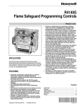
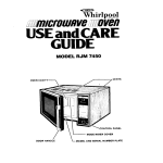
1
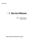
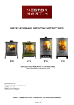
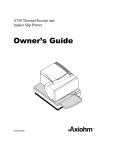
Honeywell
C7015A
Infrared Flame Detector
The C7015A Flame Detector includes a lead
sulfide photocell that is sensitive to the infrared
radiation emitted by the combustion offuels such
as natural gas, oil, and coal.
n Particularily suitable for combination or dual-fuel
applications.
q When installed properly, can supervise the pilot
flame and/or the main burner flame.
w Mounts easily on a standard
314 inch sight pipe.
n The lead sulfide photocell plugs into an electrical
socket in the C?OlSA assembly and is field replaceable.
n The lead sulfide photocell’s sensitivity to infrared
radiation is compatible with a wide range of flame
supervisory applications.
W Models are available with leadwire lengths of 30,
48 and 96 inches [0.76, 1.22,2.64 m].
W Flexible metal cable protects and electrically
shields the detector leadwires.
q Accessories available include a heat block, seal-off
adapter, reducer bushing, swivel mount and orifice
plate.
CONTENTS
F.P. * Rev. 11-91
l
OHoneywell Inc. 1991 9 Printed in U.S.A. 9 Form Number 60-2306-5
C7015A
SPECIFICATIONS
l
ORDERING INFORMATION
Specifications
SUPER TWELINE MODELS
l
SUPER TRADELINE models offer features not available on
TRADELINE or standard models, and are designed to
replace a wide range of Honeywell and competitive
controls. SUPER TRADELINE models are selected and
packaged to provide ease of stocking, ease of handling,
and maximum replacement value. Specifications of SUPER TRADELINE models are the same as those of
standard models except as noted below.
SUPER TRADELINE MODEL AVAILABLE:
C7015A1126-with 48 in. [1.22 m] leadwires; includes
104662DLead SulfidePhotocell, 110634A Bushing with
FocusingLens, 105134GrificePlate, 105061 HeatBlock,
and 390427A Reducer Bushing.
SUPER TRADELINE FEATURES:
Gritice plate (with .125 in. [3.175 mm] diameter hexagonal orifice) for reducing the detector field-of-view.
= Heat block for insulating the detector from sight pipe
temperatures higher than 125’ F [52” C] and up to
250” F [ 121” C].
l
Reducer bushing for mounting the detector on a l/2 in.
sight pipe; specifically, for replacing FireyeW lead
sulfide inframd flame detectors.
SUPER TRADELINE pack with cross reference label
and special Instruction sheet.
STANDARD MODELS
MODELS: See Table 6 for flame safeguard controls and
associated amplifiers.
DETECTOR RESPONSE: Responds to infrared radiation
with wavelengths between 0.75 and 1 .O micron.
LEAD SULFIDE PHOTOCELL: Photoconductor resistance decreases as incident radiant energy increases.
AMBIENT TEMPERATURE RATING: 125’ F [52” C]
maximum at the lead sulfide photocell.
MOUNTING:
C7015A Mount-knurled collar with 3/4-14 NPSM internal threads for mounting on a standard 3/4 in. pipe
(see fig. 1).
104662DLeadSulfidePhotocell-twoleadsforinserting
into socket in C7015A (see Fig. 8).
l
TABLE l-MODELS AVAILABLE.
With 0.125 in. [3.175 mm] diameter hexagonal orifice to reduce the detector field of view.
% insulate the detector from sight pipe temperatures higher than 125’ F [52” C] and up to 250’ F [121° Cl.
To mount the detector on a l/2 in. sight pipe, specifically to replace Fireye TM lead sulfide infrared flame detectors.
Order Information
When purchasing replacement and modernixation products from your Authorized Flame Safeguard Distributor or Wholesaler, refer to the
TRADELINE@ Catalog or price sheets for complete ordering number, or specify1. Grder nwnber, SUPER TRADELINE. if desired.
4. Replacement parts, if desired.
2. Length of leadwires (30,48. or 96 in. [0.76.1.22, or 2.44 m].
5. Accessories, if desired.
3. Lead sulfide cell order number 104662D.
If you have additional questions, need further information, or would like to comment on our products or services, please write or phone:
1. Your local Honeywell Residential and Building Controls Division Sales Office (check white pages of phone directory).
2. Residential and Building Controls Division Customer Satisfaction
Honeywell Inc., 1885 Douglas Drive North
Minneapolis. Minnesota 554224386 (612) 542-7500
(In Canada-Honeywell Liited/Honeywell Limitee, 740 Ellesmere Road, Scarborough, Ontario MlP 2V9) International sales and
service offices in all principal cities of the world. Manufacturing in Australia, Canada, Finland, France, Germany, Japan Mexico,
Netherlands, Spain Taiwan, United Kingdom, U.S.A.
2
C7015A
SPECIFICATIONS
ACCESSORIES:
110634A Bushing with Focusing Lens
105134 Orifice Plate, to reduce the detector field of view.
WIRING CONNECTIONS:
Nominal 30, 48, or 96 in. [0.76, 1.22, or 2.44 ml
leadwire+hvoNo. 18 AWG,flexible-tinnedconductom; rated for 194°F [90” C]; twistedpair-onebrown
and one white.
Leadwires enclosed in flexible metal cable-3/8 in. [9.6
mm] maximum outer diameter.
DIMENSIONS: See Fig. 1.
APPROVALS:
Underwriters Laboratories Inc. listed: File No. MP268.
Canadian Standards Association certified: Master file
LR-95329-1.
Factory Mutual approved.
Industrial Risk Insurers acceptable.
Diameter of
Hexagonal Orifice
(in.)
bml
0.125
3.175
Part No.
105134
IMPORTANT: Caution, stickers, form 96-610, are in-
105O61HeatBlocktoinsulatethedetectorfromsightpipe
temperatures higher than 125” F [52’ C] and up to
250” F [121° Cl.
105172ASeal-0ffAdapter;withglasswindowtoprevent
hot gases from reaching the lead sulfide photocell.
390427A Reducer Bushing, to mount the detector on a
lf2 in. sight pipe; specijically, to replaceFireyeTM lead
RRPLACFMENT PARTS:
104662D Lead Sulfide Photocells
Hookup Cable-R1298020; 2-wire, heat and moisture-resistant, No. 20
AWG,Teflon(TFE)insulated,ratedupto400°F[204”
C] for continuous duty; tested for operation up to 600
volts and breakdown up to 7500 volts.
118367A Swivel Mount; provides adjustable positioning
of the C7015A.
cluded with the C7015A. Underwriters Laboratories
Inc. requires that this sticker beplaced on any junction
box in which C7015A leadwires are connected. The
stickerprohibits routing any other wiring through the
junction box.
suljia2 infraredflame detectors.
Fig. l-Mounting dimensions of C7015A infrared Flame Detector and accessories, in in. [mm].
lO6172A
SEAL-OFF ADAPTER
106061
HEAT BLOCK
105134
ORlFlCE
PLATE IN
314 INCH
COUPLING
314 INCH
SIGHTING
PIPE
3/4 INCH PIPE NIPPLE
3!4 - 14 NPSM
INTERNAL THREAD
‘COLLAR.
3/4 - 14 NPSM
INTERNAL THREADS
b/4-14NPSM
EXTERNAL THREADS
FINAL THREADS
\W4-14NPSM
EXTERNAL THREADS
INSTALLING OR REPLACING A C7015A AND ACCESSORIES
105061
HEAT BLOCK
396427
REDUCER
BUSHING
C7615A
1RlNCH
5
SIGHTING PIPE
t?xza
110634A / /
BUSHING’ /
COLLAR,
3’4 - 14 NPSM
/
INTERNAL THREADS
LENS
l/2 - 14 NPSM
INTERNAL THREADS
1
I
b
THREADS
13’4.14 NPSM
EXTERNAL THREADS
3/4 - 14 NPSM
EXTERNAL THREADS
REPLACING A FIREYEw LEAD SULFIED DETECTOR
3
MXM
60-2306-5
C7015A
OPERATION
l
INSTALLATION
Operation
refractory radiation, thus making it fluctuate. This fluctuating
action can simulate the flickering radiation from a flame,
and infrared radiation may be present even after the
refractory has visibly stopped glowing. Therefore, be very
careful when applying an infrared detection system to be sure
it responds only to flame.
OPERATION OF INFRARED DETECTORS
Infrared detectors can be used with gas, oil, coal, or dualfuel flames. Since more than 90% of the total flame radiation
is infrared, these detectors receive ample radiation and can
detect weak fkunes as well as flames of higher intensity.
The lead sulfide cell used in the detector cannot diitinguish between the infrared radiation emitted by hot refractory and the infrared radiation from a flame. Therefore, the
infrared detection system includes an amplifier that responds only to the flickering characteristic of flame radiation
and rejects the steady radiation characteristic of hot refractory.
Unfortunately, smoke or fuel mist within the combustion
chamber can intermittently reflect, bend, or block the hot
CELL CONSTRUCTION
,The photosensitive material used in the infrared detector
is lead sulfide. The electrical resistance of lead sulfide decreases when exposed to infrared radiation. If a voltage is
applied across the lead sulfide photocell, current flows when
the cell is exposed to infrared radiation.
Installation
When a flame is present, the lead sulfide photocell
detects the infrared radiation generated. The C7015A produces an electric signal that is sent to the amplifier in the flame
safeguard control. The amplified signal pulls in the flame
relay in the flame safeguard control to allow proper operation.
Because it is necessary for the detector to actually see the
flame, it is best to locate the detector as close to the flame as
physical arrangement, temperature, and other restrictions
permit. These restrictions are described in detail below.
WHEN INSTALLING THIS PRODUCT.. .
1. Read these instructions carefully. Failure to follow
them could damage the product or cause a hazardous condition.
2. Check the ratings given in the instructions and on the
product to make sure the product is suitable for your application.
3. Installer must be a trained, experienced flame safeguard control service technician.
4. Afterinstallationiscomplete,checkoutproductoperation as provided in these instructions.
DETERMINE THE LOCATION
Before beginning the actual installation, determine the
best location for mounting the flame detector. Carefully
consider the factors discussed in this section before establishing the location.
A! CAUTION
(
I
\
1. Disconnect power supply before beginning installation to prevent electrical shock and equipment damage, there may be more than one
disconnect.
2. All wiring must be NBC Class 1 (line voltage).
3. Use the C7015A only with Honeywell lead
sulfide photocells (part no. 104662D) and flame
signal amplifiers specified, (see Table 6).
TEMPERATURE
The sensitivity of the lead sulfide cell decreases as its
temperature increases. Up to 125’ F [52’ Cl, the loss in
sensitivity is negligible, but temperatures above this point
must be avoided. Under normal temperature conditions (below 125” F [.52’ Cl, the life of the lead sulfide cell should be
unlimited. The quickest check for excessive temperature is
simply to grasp the detector-it should not be too hot to hold
comfortably in your bare hand.
Several methods are available for cooling the lead sulfide
photocell including ventilating the sight pipe and installing a
pipe nipple, seal-off adapter, and/or heat block between the
sight pipe and the detector. Refer to Installing Accessories,
page 8.
Proper flame detector installation is the basis of a reliable
flame safeguard installation. Refer to the burner manufacturer instructions and instructions below. Carefully follow
instructions for the best possible flame detector application.
BASIC REQUIREMENTS
Because all flames produce infrared radiation, a C7015A
Infrared (lead sulfide) Flame Detector can be used to prove
the presence of a flame in a combustion chamber. The
detector is mounted outside the combustion chamber. Screw
themountingcollartooneendofasightpipeinsertedthrough
the wall of the combustion chamber. The lead sulfide photocell in the detector sights the flame through the sight pipe.
SIGHTING
The infrared detector must continually sight a stable
portion of the flame being detected. The detector is commonly applied to detect both the gas pilot and main gas flame,
or thegaspilot and main oil flame.ln either case, the detector
must be carefully aimed at the intersection of the pilot and
muinflame. A Swivel Mount (Honeywell part no. 118367A)
4
C7015A
INSTALLATION
is available to facilitate flame sighting after the C7015A is
mounted.
FIELD OF VIEW
A lead sulfide photocell, like other photocells, views an
area rather than a point. It is unable to pinpoint pilot flame
locationaseasilyasaflamerod.Ifthedetectoristoproveonly
the pilot jlame, it must view only a part of the flame so it can
detect the pilot only when it is large enough to successfully
light the main burner. The viewing area must not be so large
that a weak and wavering pilot flame could energize the
photocell and cause the flame relay to pull in.
The area viewed by the photocell depends on:
1. Diameter of the opening in front of the cell.
2. Distance from the cell to the opening.
3. Distance from the opening to the area to be viewed.
Fig. 2 shows three ways of reducing the field of view,
assuming that the distance from the viewing opening to the
flame or refractory cannot be changed. These are (1) lengthening the sight pipe, (2) reducing the diameter of the sight
pipe, and (3) installing an orifice plate in front of the photocell. Combinations of these methods can be used.
pipe diameter is reduced, the effect is the same as adding an
orifice plate to the pipe as discussed below.
Fig. P-Methods of reducing C7015A Detector
field-of-view.
AREA
0
/M-
g/j___-----\ UNRESTRICTED VIEW
3 BY
LENGTHENING
THE SIGHT PIPE
CHANGING PIPE LENGTH OR SIZE (DIAMETER)
Theeffectorchangingthelengthofthesightpipeisshown
in Tables 2 and 3.
Changing the diameter of the sight pipe is not as simple as
changing the length,because the C7015A mount and mounting accessories are all sized for 3/4 in. pipe. When the sight
TABLE 2-DIAMETER OF AREA SIGHTED THROUGH VARIOUS LENGTHS OF 3/4 -IN. PIPE
WITHOUT ORIFICE, IN IN.
Distance From End of Pipe To Sighted Area-in.
Length of
Pip&.
6
12 1 18 1 24 1 30 1 36 I 42 I 48 I 54 I 60 1 66 1
7
8
1.5
1.4
2.3
2.1
3.1
2.8
3.9
3.5
4.7
5.5
6.3
7.1
1
4.2
4.9
5.6
6.3
1
8.0
8.7
9.6
7.1 7.7 8.5
72
10.4
9.1-
TABLE 3-DIAMETER OF AREA SIGHTED THROUGH VARIOUS LENGTHS OF 3/4 IN. PIPE
WITHOUT ORIFICE. IN MM
Length of
Distance From End of Pipe To Sighted Area-mm e
Pipe-mm 152.4 I 304.8 I 457.2 I 609.6 I 762.0 1 914.4 I 1066.8 11219.2 I 1371.6 I 1524.0 11676.4 11828.8
25.4
160.0 1 302.3 1 447.0 1 589.3 1 721.4 876.3 I
Over 1016.0
60-2306-5
C7015A
INSTALLATION
INSTALLING AN ORIFICE PLATE
AnorificeplatewithahexagonalorificediameterofO.125
in. [3.2 mm] is available for the C7915A Infrared Flame
Detector. The orifice can be mounted in front of the cell in the
seal-off adapter or in a standard 314 in. coupling. (Refer to Fig.
1.)
The size of the sighted area at various distances can be
determined from Table 4 or 5. For example, if the distance
fromthephotocelltoa0.125 in. L3.175 mm] diameterorifice
is4in. [101.6mm],andfromtheorificetotheflamejunction
(or refractory) is 36 in. [914.4 mm], the dieter of the
sighted area is 2.4 in. [70 mm].
Fig. 3 shows how a typical orifice plate restricts the view
of a small area around the flame junction.
TABLE ADIAMEXER OF AREA SIGHTED THROUGH ORIFICE, IN IN.
6
-
1.1
1.6
I
2.1
2.6
3.2
TABLE 5-DIAMETER OF AREA SIGHTED THROUGH ORIFICE, IN MM
Fig. 3-4sing orifice plate to restrict detector field of view to intersection of pilot and main flame, or to
sniall area of hot refrktory.
WlTHOUT ORIFICE PLATE
PILOT
\
HOT REFRACTORY
\
WITH OFilflCE PLATE
MAIN FLAME
PILOT,
\
6
HOT REFRACTORY\
MAIN FLAME\
C7015A
INSTALLATION
RESPONSE TO HOT REFRACTORY
Fig. 4--C7015A infrared Flame Detector aimed
at side wall of combustion chamber.
Although the infrared amplifier will not respond to steady
radiation, as produced by hot refractory, be careful to protect
the infrared detector from hot refractory radiation because of
two possible conditions, shimmer and raa’iation saturation.
a. Shimmer-Turbulent hot air, steam, smoke, or fuel
spray in the combustion chamber can reflect, bend, or
block the steady infrared radiation emitted by a hot
refractory. These conditions can change the steady
radiation from a hot refractory into a fluctuating radiation. If these fluctuations occur at the same frequency
as that of a flickering flame, they will simulate flame
and will hold in the flame relay after the actual burner
flame has been extinguished.
b. Radiation saturation--Steady hot refractory radiation
can become strong enough to mask the fluctuating
radiation of the flame. This is similar to the effect of
holdingupacandleinfrontofthesun-thelightofthe
sun is so strong that the candle light cannot be seen. If
radiation saturation is extreme, the flame relay will
drop out, and the system will shut down as though a
flame failure has occurred.
Both of these problems will be minimized by aiming the
detector at a portion of the refractory that is:
as cool as possible.
as far from the cell as possible.
as small as possible reduce the field of view, see Figs.
2and3.
Refractory temperatures in the combustion chamber will
vary with combustion chamber design but generally, the end
wall of the chamber will be the hottest point. It will normally
be best to aim the detector at the side wall of the refractory
(Fig. 4), at a point above the refractory (Fig. 5), or at the floor
of the combustion chamber (Fig. 6).
MAIN BURNER FLAME
-
-
_\
-AREA VIEWED BY C7015A ’
\
.
I
‘Y
I
‘, I
.
I
,
,
__-----
_/-- _-M245,
Fig. 5-C7015A Infrared Flame Detector aimed
at a point above refractory.
l
BURNER
FACEPLATE
/
/
l
l
//
,l‘-
I
!
DETECTOf 3 VIEWS AREA
ABOVE THE REFRACTORY
--__
&ii /cd
- -
I
//
I --_
P;- +--/___
I
cr
i-1
-7
-
----‘n
_.=’
PILOT
AND MAIN FLAME
.
SIGHTING SUMMARY
When sighting the detector, two important factors to
consider are: (1) proper sighting of the flame being detected
(normally the pilot/main Rame junction), and (2) avoiding
hot refractory sighting.
A typical sighting arrangement is shown in Fig. 4. The
detector is aimed at the intersection of the pilot and main
flames, and at a relatively cool side of the combustion
chamber. The detector, in this case, would be located as close
as possible to the burner to sight the maximum depth of the
&me and reduce the effect of variations in the main flame
pattern.
The detector can also be sighted from a point below and
close to the burner with the line-of-sight above the refractory
(Fig. 5).
The third method is to aim the detector from above the
burner, sighting a portion of the refractory floor (Fig. 6). This
type of application requires that the pilot flame be carefully
sighted from the side. The detector should not be sighted over
the shoulder of the pilot because the chances increase of
sighting a pilot too small to satisfactorily light the main flame,
Theactualareaofhotrel?actorysightedshouldbeassmall
as possible and consistent with proper sighting of the flame.
Refer to Figs. 2 and 3 for methods of reducing the ama of hot
refractory sighted.
\\
i
i&
.
. .
1-J
I
_/-\.
I
_M-M305.3
\ \L_----
Fig. 6-C7015A Infrared Flame Detector aimed
at floor of combustion chamber.
,‘P--__
,
--__
I
,
--__
I
, /
-3.
.’ 1
CENTER LINE
\
REFRACTORY FLOOR
’ \ AREA VIEWED BY C701
\\
I
___------,,,
\L_---
7
60-2306-5
C7015A
INSTALLATION
mounting details, refer to form 60-0361 for the 118367A
Swivel Mount)
CLEARANCE
Make sure there will be enough mom to easily mount the
sight pipe, flame detector, and all required accessories, and to
remove th flame
e
detecto for
r troubleshooting and servicing.
REDUCER BUSHING
To mount the detector on a l/ 2 in. sight pipe, speci&zlly
if replacing a FireyeW lead sulfuie detector, install a
390427 A Reducer Bushing (Fig. 1).
INSTALLING THE SIGHT PIPE
Thelocationofthesightpipeisthemostcriticalpartofthe
installation. A 3/ 4 in. black iron sight pipe is recommended.
Do rwt use a stainless steel or galvanized pipe because its
internal surface blackens with use as deposits from the
combustion chamber accumulate on it. Initially, its shiny
intemalsurfacereflectsinharedradiation, whichcouldresult
in a satisfactory flame signal even though the pipe may be
improperly located. As it blackens, less inhare dradiation is
reflected and the flam e signal becomes marginal.
Because no two situations a m the same, the length and
sighting angle of the pipe must be determined at the time and
placeofinstallation.Generally,itisdesirabletohavethesight
pipe tilting downward to prevent soot or dirt buildup.
ORIFICE PLATE
To reduce the detector field-of-view, and restrict it to the
intersection of the pilot and main flame, or to a small area of
hotrefractory (see Fig. 3), install a 105 134 Orifice Plate. The
or&e plate can be inserted into a standard 3/ 4 in. pipe
coupling (Fig. 1) or into the seal-off adapter, if used.
MOUNTING SIGHT PIPE
Thmadoneendofthepipetofitthemountingcollaronthe
detector (or an accessory, if used, see Fig. 1). Cut the pipe to
the desired length (as short as practical). T oavoid conducting
excessive heat back to the lead sulfide photocell, the sight
pipeshould not extendmore than halfway into the refractory.
Tack weld the pipe to the wall in a trial position (Fig. 9) Do .
not permanently weld the sight pipe in place until ajter
completing the Adjustments and Checkout, page 10.
PREPARE HOLE IN WALL OF COMBUSTION
CHAMBER
Form a hole of the proper diameter for the sight pipe in the
walioftbecombustionchamberattheselectedlocation.Flare
the hole (Fig. 9) to leave room for small adjustments of the
sighting angle. The taper of the hole should be about 1 in. for
every 3 in. 125. 4 mm for every 76.2 mm] of wall thickness.
NOTE: If you use a Swivel Mount (part no. 118367A ) and
yo u arepositive about the location and sighting angle, you
can permanently weld the pipe.
INSTALLING ACCESSORIES
It may be necessary or desirable to install accessories
between the sight pipe and the detector. This section describes the installation of these accessories.
PIPE NIPPLE
A 3/ 4 in. pipe nipple, 6 to 8 in. [ 152 to 203 mm] long, can
be inserted between the sight pipe and the C7015 A Mount
(Fig. 1) to help cool the lead sulfid e cell. Usin gthe pip enipple
will also reduce the viewing area of the detector, see Table 2
or 3).
SIGHT PIPE VENTILATION
It may be necessary to ventilate the sight pipe to cool the
detector.
For a negative pressure combustion chamber, drilling a
few holes in th e section of the sight pipe outside of the
combustion chamber allows air at atmospheric pressure to
flow through the sight pipe into the chamber. A perforated
pipe nipple between the sight pipe and the flame detector can
also be used. See Fig. 7.
For a positive pressure combustion chamber, connect a
supply of pressurized air from the burner blower to flow
throughthesightpipeintothechamber.Theairpressuremust
be greater than the chamber pressure.
SEAL-OFF ADAPTER
To protect the detector from hot gases, install a 105 172A
Seal-Off Adapter (Fig. 1). The adapter has a glass window
that prevents hot gases from reaching the lead sulfide photocell.
HEAT BLOCK
To insulate the detector from sight pipe temperatures
above 125” F [52” Cl, install a 105061 Heat Block (Fig. 1).
The device is made of nonheat-conductive, laminated plastic
that prevents heat hor n being conducted from the sight pipe
to the detector. It can withstand temperatures up to 250” F
[121 ° C].
Fig. 7-Forced air cooling.
DETECTOR
PIPE NIPPLE
PIPE TEE
SIGHT
PIPE
”
MOUNTING THE DETECTOR
Before mounting the C7015A , install the lead sulfide
photocell (if not installed already).
Unscrew the bushing from the cap, plu the photocel
g
into
l
the cell mount, and screw the bushing back into the cap (Fig.
8). The bushing also includes a focu&n g lens to concenuate
available radiation on the photocell face.
Mount the C7015 A Detector onto the sight pipe, heat
block, orotheraccessory (Figs. 1 and 9). Screw the mounting
collar onto the sight pipe or accessory.
+@a
COOLING AIR
APPLIED UNDER
SWIVEL MOUNT
To facilitate flame sighting, a Swivel Mount (part no.
118367A ) is available. The Swivel Mount requires a reducer
of the proper size to mount it onto the sight pipe. (For
8
c701 !?A
INSTALLATION
3. The detector comes with 30,48, or 96 in. [0.76,1.22,
or 2.44 m] leadwires inside a flexible metal cable. The
leadwires consist of a twisted pair-one brown and one
white. The two no. 18 AWG flexible-tinned leadwires are
rated for 194’ F [90” C]. The cable protects and electrically
shields the leadwires.
4. If the leadwires are not long enough to reach the
terminal strip or wiring subbase, make the required splices in
a junction box (see IMPORTANT below).
5. If splicing is necessary, use moisture-resistant no. 14
wire suitable for at least 167” F [75” C] if the detector is used
withaflamesafeguardprimarycontrol,oratleast 194°F [90”
C] if used with a flame safeguard programming control.
6. For splicing in high temperature installations, use
Honeywell specification no. R1298020 or equivalent for the
F leadwire. (This wire is rated up to 400” F [204” Cl for
continuous duty. It is tested for operation up to 600 volts and
breakdown up to 7500 volts.) For the other leadwire, use
moisture-resistant no. 14 wire selected for a temperature
rating above the maximum operating temperature.
Fig. 8-installing lead sulfide photocell.
CAP
\
, MOUNTING
PLUG-IN LEAD SULFIDE CELL
(PART NO. 104662D)
METAL CABLE
SHIELDS LEADWIRES
PHOTOCELL
SOCKET
FOCUSING LENS I
EPOA
Fig. O-Mounting C7015A Infrared Flame
Detector (and accessories).
COMEUSTlON
CHAMBER WALL
-J
REFRACTORY
IMPORTANT:
MAIN
/ FLAME
a. Flame detector leadwires must be as short aspossible. The maximum leadwire lengthfrom thejlame
detector to the flame safeguard control is 50 ft
[15.2 m].
TEMPORARY
TACK wLO\
6. Extensions to the flame detector leadwires must be
run alone in either rigid orflexible metal conduit.
When frame detector leadwires exit a conduit, they
must be as short as possible, twisted, and not be
included in bundles or channels that contain other
wires. Rigid metal conduit is preferred when flame
detector leadwires are extended butflexible metal
conduit may be used tfit is supported to minimize
movement.
p,T FLARED HOLE
-3/4 INCH BLACK
IRON SIGHTING PIPE
C.
TO JUNCTION
80X OR SUBBASE
M304.5
WIAmG (F&s. 10 and 11)
The jlame detectorjlexible cable shield must be
grounded to the flame safeguard control subbase
either directly or through the metal cabinetlconduit
system that contains the flame safeguard control
subbase andjlame detector leadwires.
d. When flame detector leadwires are routed through
junction boxes, identifr the junction boxes with the
pressure-sensitive labels provided wiih the flame
detector cform 96-610).
.I CAUTION
/\
Disconnect power supply before beginning installation to prevent electrical shock and equipment
damage; there may be more than one disconnect
involved.
‘e. UNDERWRITERS LABORATORIES INC. REQUIRES THAT THE JUNCTION BOX BE
MARKED TO INDICATE THATNO OTHER WIRING CONNECTIONS CAN BE ROUTED
THROUGH IT. APPLY CAUTION STICKER
(FORM 96410, FURNISHED) TO THE JUNCTION BOX.
1. All wiring must comply with applicable electrical
codes, ordinances, and regulations. Use NRC Class 1 wiring.
,2. Keeptheleadwiresfromtheflamedetectortotheflame
safeguard control subbase as short as possible. Capacitance
increases with leadwire length, reducing the signal strength.
The maximum permissible leadwire Iength is fifty feet. The
f Maximize the separation between ignition transformer high voltage wires and the jlame sensor
wires to avoid ignition interference.
ultimate limhingfactor in leadwire length is the frame signal
current/voltage. Refer to Table 6, Adjustments and Check-
out, page 10.
9
60-2306-5
C7015A
INSTALLATION
l
ADUSTMENTS AND CHECKOUT
Fig. 1 l-Typical wiring of C7015A Infrared
Flame Detector to distant wiring subbase or
terminal strip.
Fig. 1 O-Typical wiring of C7015A Infrared
Flame Detector to nearby wiring subbase or
terminal strip.
FLEXIBLE CABLE
(MECHANICALLY
SUPPORT TO
MINIMIZE MOVEh
cmi5A
FLEXIBLE CABLE (MECHANICALLY
SUPPORT TO MINIMIZE MOVEMENT)
GROUNDlNG
STRAP,
I
RING SUBBASE
OR TERh
I
BX CABLE, SHIELDED
CABLE, OR TWISTED
PAIR; MUST BE ALONE
IN CONDUIT.
I
FLAME SAFEGUARD
CONTROLS SUBBASE
I
JUNCTION BOX A
1 BROWN WIRE AND 1 WHITE WIRE FROM THE C7015A; CONNECT
lNSlDE JUNCTlON Box; COLOR NOT IMPORTANT; LEADWIRES
FROM JUNCTION BOX NEED NOT BE PHASED OR POLARIZED.
n
1 1 BROWN WIRE AND 1 WHITE WIRE FROM THE C7015A. CONNECT TO
FLAME SAFEGUARD CONTROL’S SUBBASE, COLOR NOT IMPORTANT,
KEEP WIRES AS SHORT AS POSSIBLE. AND TWIST THEM.
APPLY CAUTION STICKER, FORM NO. 96-610 SUPPLIED WITH
Ci’O15A. TO THIS JUNCTION BOX. BOX MUST BE GROUNDED.
USE RIGID CONDUIT. OR SUPPORT FLEXIBLE CONDUIT TO
.MINIMIZE MOVEMENT.
AFLEXIBLE CABLE MUST BE RUN To FLAME SAFEGUARD CONTROL ’S
SUBBASE AND GROUNDED WHERE THE EXPOSED WIRES BEGIN.
CONDUIT MUST BE RUN TO FLAME SAFEGUARD CONTROL’S
SUBBASE AND GROUNDED THERE. KEEP EXPOSED WIRES AS
SHORT AS POSSIBLE AND TWIST THEM.
IA3046
Adjustments and Checkout
IMPORTANT: Before welding the sight pipe in its final
location, complete the AdjustmentsandCheckout Tests
below and any tests required by the burner man@acturer.
ADJUST DETECTOR SIGHTING POSITION
For initial burner lightoff, consult the burner manufacturer
instructions or flame safeguatd control instructions.
With the flame detector installed and the burner running,
adjust the sighting position of the detector for optimum flame
signal.
Most existing Honeywell flame safeguard controls have a
flamecurrentjackonthecontrolplug-inflameamplifier.The
flame signal (current) can be measured with a volt-ohmmeter
such as the Honeywell W 136A with a zero to 25 microampdc
scale. To measure the flame current (signal), a Cable Connector (part number 1%146, included with W136A) must be
used with the meter. With the W136A (or equivalent) positioned to the zero to 25 microamp scale, make connections
from the meter probes to the two ends of the cable connector
plug, red to ted, black to black The plug end of the connector
pluginsertsdirectlyintotheamplifierflamejack(seeFig. 12).
If the flame safeguard control is using a R7248B AMRLICHECP amplifier, the red flame-indicating lamp on the
amplifEr should blink at the same rate that the flame is
flickering (may be as high as 20 times a second). If the lamp
is ON (bright) continuously or not blinking while measuring
the flame current, replace the amplifier.
Refer to Table 6 for the minimum acceptable flame
currents for the amplifiers and associated flame safeguard
controls.
The R7748B AMRLI-CHECKTM ; R7848A and R7848B
(AMPLI-CHECKTM)amplifiersusedwiththeBCS7700and
7800 SERIES flame safeguard controls respectively, have a
dc voltage flame signal output.
To measure flame signal voltages when using a R7748B
amplifier, a 20,000 ohm/voltmeter with a zero to 5 or 10 Vdc
scale is suggested To measure the flame signal voltage when
using R7848A,B amplifiers, a volt-ohm meter with a minimum sensitivity of one megohm/volt is recommended. The
flame signal (voltage) measurements are made as shown in
Figs. 13 and 14. The positive (red) meter lead is connected to
the positive (+) control jack and the negative (black) meter
lead to the negative (-) control jack (Corn jack with 7800
SERIES controls). If the BCS 7700 and 7800 SERIES
controls have the Keyboard Display Module, a zero to five
Vdc voltage is displayed on the module. Refer to Table 6 for
minimum and maximum flame voltages for the amplifiers
C7015A
ADJUSTMENTS AND CHECKOUT
and associated flame safeguard controls.
Move the detector and sight pipe around to sight the flame
at various positions and angles. Try to get a maximum steady
meter reading. The signal must be above the minimum
acceptable current/voltage listed in Table 6.
Measure the fIame signal for the pilot alone, the main
burner flame alone, and both together (unless monitoring
only the pilot flame when using an intermittent pilot, or only
themain burner flame when using direct spark ignition). Also
measure the flame signal at high and low firing rates and
while modulating in between (as applicable). With the detector in its final position, all required fhune signals must be
steady and as specified in Table 6. If you cannot obtain the
proper signals, refer to the Troubleshooting section.
Fig. K&Measuring BCS 7700 Flame Safeguard
Control flame signal voltage.
Fig. 12-Measuring microamp flame Signal.
W136A
TEST METER
SELECTOR
SWITCH,
PLUG-IN FLAME
SIGNAL AMPLIFIER
I
PROBES
\
\ ECS 7700 CHASSIS MODULE
196146 METER
CONNECTOR
FOOTMOUNT
E2512A
Fig. 14-Measuring 7800 SERIES Flame
Safeguard Control flame signal voltage.
RED CONNECTOR
CK CONNECTOR
METER‘
LEAD
El 208
TABLE 6-FLAME SIGNAL
1 Minimum 1 Maximum 1 Minimum 1
Maximum
Expected
Acceptable
Acceptable
Expected
Flame
Voltage
Steady Voltage
Current
Steady Current
Signal
(Vdc)
(microamp)
Amplifier
Flame Safeguard Control
(microamp)
(Vb)
2.25
5.0
BC7OOOL; R4075C,D,E;
R7248A
R4138CD; R414OG;L;M
BC7OOOL; R4075C,D,B;
3.5
5.0
R7248B
AMF’LI-CHECK~ R4138CD; R414OGL.M
4.0
5.5
R7258A
R4150
4.98
2.2
BCS 7700
R7748B
AMPLI-CHECKTM
5.0
1.25
RM78OOE,G,L,M; RM7823A;
R7848A
RM7838A,B; RM784OE,G,L,M
I RM7885A: RM789OA,B;
I
I
RM7895A;B,C,D
5.0
1.25
R7848B
RM78OOE,G,L,M; RM7823A;
AMPLI-CHECX= RM7838AB; RM784OE,G,L,M;
RM7885A; RM789OA,B;
RM7895A,B,C,D
11
60-2306-5
C7015A
ADJUSTMENTS AND CHECKOUT
PILOT TURNDOWN TEST
Ifthedetectorisusedtoproveapilotflamebeforethemain
fuel valve( can be opened, perform a Pilot Turndown Test
before welding the sight pipe into position. Follow the
procedures in the instructions for the appropriate flame
safeguard control, and the burner manufacturer instructions.
solids instead of liquids, or liquids instead of gases.) When
the maximum refractory temperature is reached, close all
manual fuel shutoff valves or open theelectricalcircuit of all
automatic fuel valves. Visually observe when the burner
flame goes out. After the flame goes out, measure the time it
takes for the flamerelay 2K to drop out. Watch or listen to the
flame relay to determine when it drops out. If the flame relay
fails to drop out within four seconds, the infrared detector is
sensing theradiation from hot refractory. Immediately terminate the firing cycle, (lower the set point of the burner
controller, or set the fuel selector switch to OFF). Do not open
the master switch.
HOT REFRACTORY SATURATION TEST
Testtobesureradiationfromhotrefractorydoesnotmask
the flickering radiation of the l&me itself.
Start the burner and monitor the flame signal during the
warmupperiod.Adecreaseinsignalstrengthastherefmctory
heats up indicates hot refractory saturation. If saturation is
extreme, the flame relay 2K (in the flame safeguard control)
will drop out and the system will shut down as though a flame
failure has occurred.
If hot refractory saturation occurs, the condition must be
corrected. Add an orifice plate in front of the photocell to
restrict the viewing area. If this does not work, resight the
detector at a cooler, more distant background. Lengthening
the sight pipe or decreasing the pipe size (diameter) may also
be helpful. Continue adjustments until hot refractory saturation is eliminated.
NOTE: Some burners continue to purge their oil lines between the valves and nozzles even though the fuel valve(s)
is closed. Terminating the firing cycle (instead of opening
the master switch) will allow purging of the combustion
chamber. This will reduce a buildup of fuel vapors in the
combustion chamber caused by oil line purging.
If the detector is sensing hot refractory radiation, the
condition must bc corrected. Add an orifice plate in front of
the photocell to restrict the detector viewing area. If this does
not work, resight the detector at a cooler, more distant part of
the combustion chamber. While resighting the detector,
remember that it must also properly sight the flame. Lengthening the sight pipe or decreasing the pipe size (diameter)
may also be helpful. For details, refer to Installation. Continue adjustments until hot refractory hold-in is eliminated.
HOT REFRACTORY HOLD-IN TEST
Test to make certain that hot refractory will not cause the
flame relay 2K (in the flame safeguard control) to stay pulledin after the burner flame is extinguished. This condition
would delay response to flame failure and also would prevent
a system restart as long as the infrared radiation emitted by the
hot refractory is detected.
First check the plug-in flame signal amplifier by initiating
a burner cycle. When the programmer stops in the run
position, terminate the firing cycle while the refractory is at
a low temperature. Measure the time it takes for the flame
relay 2K to drop out after the flame goes out. Watch or listen
to the flame relay to determine when it drops out. If the flame
relay fails to drop out within four seconds, open the master
switch and replace the amplifier.
Infrared detectors can respond to infrared radiation emitted by a hot refractory, even when the refractory has visibly
ceased to glow. Infrared radiation from a hot refractory is
steady, whereas radiation from a flame has a flickering
characteristic.Theinliareddetectionsystemrespondsonlyto
a flickering infrared radiation; it can reject a steady signal
from hot refractory. However, the refractory’s steady signal
can be made to fluctuate if it is reflected, bent, or blocked by
smoke or fuel mist within the combustion chamber. Be
careful when applying an infrared system to ensure its
response to flame only.
To check a C7015A Inj-ared Flame Detector for hot
refractory hold-in, operate the burner until the refractory
reaches its maximum temperature. If the installation has a
multifuel burner, burn the fuel most likely to reflect, bend, or
obscure the hot refractory’s steady infrared radiation, (burn
IGNITION INTERFERENCE TEST
It is possible for infrared amplifiers to respond to ignition
spark electrical noise (interference) under certain conditions.
Avoid ignition interference by locating the transformer as
close as possible to the burner ignition electrode (preferably
not on the control cabinet). You can also use an ignition cable
that suppresses electrical noise (such as the type of cable used
in automobiles). Maintain maximum separation of flame
sensor and ignition wiring.
To determine if an infrared flame amplifier responds to
ignition interference, complete the following test sequence:
1. CLOSE MANUAL FLJBL VALVES TO THE PILOT
AND MAIN BURNER.
2. Connect a flame signal meter to the amplifier and start
the burner.
3. There should be no flame signal when the ignitor is
energized (momentary meter movement maybe observed
when the flame safeguard control switches a load on or off).
WELD THE SIGHT PIPE
After adjustments have been made and an acceptable
flame signal obtained, remove the detector and weld the sight
pipe in its final position, (if you are using a swivel mount, the
pipe may already be welded). Then reinstall the detector.
12
ADJUSTMENTS AND CHECKOUT
FINAL CHECKOUT
Before putting the burner into service, check out the
installation by using the Checkout procedures in the instructions for the appropriate flame safeguard control. After
completing the checkout, run the burner through at least one
complete cycle to verify proper operation.
!
n
l
C7015A
TROUBLESHOOTING
CAUTION
Do not put the system into operation until all
Checkout tests in the instructions for the appropriate flame safeguard control and any specified in the
burner installation instructions are satisfactorily
completed.
Troubleshooting
A! CAUTION
,
v
PRELIMINARY INSPECTION
1. Makesurethat the flame is properly adjusted and is not
too lean.
2. Checkfortheproperlinevoltage. Makesurethemaster
switch is closed, connections are correct, and power supply
is of the correct voltage and frequency.
3. Check the detector wiring for defects including:
. incorrect connections.
wrong type or size of wire.
deteriorated wire.
open circuits.
short circuits.
leakage paths caused by moisture, soot, or dirt.
4. With the burner running, check the temperature at the
detector. If it exceeds 125” F [52” Cl:
add additional insulation between the wall of the
combustion chamber and the detector.
add a shield or screen to reflect radiated heat away
from the detector.
add cooling (refer to Sight Pipe Ventilation, see
Installation).
\
1. Be extremely careful while troubleshooting the
detector; line voltage is present on some of the
terminals on the wiring subbase or terminal strip
when power is on.
2. Open the master switch to disconnect power
before removing or installing the detector, there
may be more than one disconnect involved.
l
l
l
l
l
If you cannot obtain a satisfactory flame signal while
adjusting the sighting position of the detector, follow these
procedures. If you encounter other problems in the system,
refer to Troubleshooting in the instructions for the appropriate flame safeguard control.
EQUIPMENT REQUIRED
1. Voltmeter(HoneywellW136Aorequivalent)withOto
300 Vat scale.
2. Microammeter (Honeywell W136A or equivalent)
with 0 to 25 microampdc range.
3. W136ACableConnector,partno. 196146, or 117053
Meter Connector Plug or equivalent (required for some
meters).
4. A volt-ohm meter with a zero to 5 or 10 Vdc scale and
a sensitivity of 20,000 ohm/volt is suggested for BCS7700
control flame signal measurements. If the control has the
Keyboard Display Module option, flame voltage is displayed
on the module.
5. A one megohm/volt meter with a zero to 5 or 10 Vdc
scale is recommended for 7800 SERIES control flame voltage measurements. If the control has the Keyboard Display
Module option, flame voltage is displayed on the module.
6. Replacement parts-see Specifications.
PROCEDURE FOR A LOW METER READING
1. Remove the detector and clean the focusing lens with
a soft, clean cloth.
2. If the focusing lens is broken or damaged, or if it is
coated with a substance that cannot be cleaned off, replace the
110634A Bushing (which includes the focusing lens).
3. Clean the inside of the sight pipe before reinstalling the
detector.
4. If the meter reading is still too low, replace the lead
sulfide cell (Fig. 8).
5. If the meter reading is still too low, replace the plug-in
amplifier.
6. If you still cannot obtain a proper flame signal, replace
the C7015A Infrared Flame Detector.
PROCEDURE FOR A ZERO METER READING
1. Replace the lead sulfide cell (Fig. 8). Then recheck the
flame signal.
2. If there is still no flame signal, replace the plug-in
amplifier.
3. If you still cannot obtain a meter reading, replace the
entire C7015A Infrared Flame Detector.
TROUBLESHOOTING PROCEDURES
Firstperfonn thePreliminary Inspection. Then follow the
applicable procedures for either a low reading or a zero
reading on the flame signal meter. After reinstalling the
detector, recheck the meter reading. Adjust the position of the
detector to try to obtain the proper fIame signal. If the
procedures are completed and a satisfactory flame signal
cannot be obtained, replace the detector.
IMPORTANT: At the completion of troubleshooting, be
sure to perform the Adjustments and Checkout, page
10.
13
60-2306-5
C7015A
SERVICE
n.
PERIODIC MAINTENANCE
1. Clean the focusing lens andsightpipe when necessary.
Remove the detector and use a soft, clean cloth. lhe lens does
not require removal to clean it. If it is broken or damaged, or
itiscoatedwithasubstancethatcannotbecleanedoff,replace
the 110634A Bushing, which includes the focusing lens.
2. Keep the flame detection system adjusted for the
smoothest, most reliable operation as recommended by the
burner manufacturer.
3. Replace the bushing with focusing lens or the lead
sulfide photocell (Fig. 8) only when necessary to obtain
1 CAUTION
1. Onlyusequalifiedservicetechnicianstoattempt
to service or repair flame safeguard controls and
burner systems.
2. Open the master switch to disconnect power
before removing or installing the detector.
3. If the C7015A is disassembled for any reason
(e.g., to replace the lead sulfide cell or bushing
with focusing lens), you must perform the Adjustments and Checkout, page 11.
proper operation.
14
C7015A
TABLE OF CONTENTS
Table of Contents
Application and Features 1..................................................................................................................................................
Page
1
Specifications ......................................................................................................................................................................
Ordering Information ..............................................................................................................................................
Dimension Drawings ................................................................................................................................................
2
2
3
Operation ............................................................................................................................................................................
4
Installation ..........................................................................................................................................................................
Basic Requirements ..................................................................................................................................................
Installing the Sight Pipe ...........................................................................................................................................
Installing Accessories ................................................................................................................................................
Mounting the Detector .............................................................................................................................................
Wiring .......................................................................................................................................................................
4
4
8
8
8
9
Adjustments and Checkout .............................................................................................................................................
10
13
Troubleshooting ...............................................................................................................................................................
Service .............. ..~.~“~.....~.~.“.........~....................................................................................................~ ......................... 14
Periodic Maintenance ............................................................................................................................................. 14
Tables
Table I -Models available ....................................................................................................................................... 2
Table 2 -Diameter of area sighted through various lengths of 3/4 inch pipe without orifice, in in.. ................... .5
Table 3 -Diameter of area sighted through various lengths of 3/4 inch pipe without orifice, in mm .................. .
6
Table 4 -Diameter of area sighted through orifice, in in .......................................................................................
6
....................................................................................
Table 5 -Diameter of area sighted through orifice, in mm
Table 6 -Flame Signal ............................................................................................................................................ 11
Figures
Fig. 1 -Mounting dimensions of C7015A Infrared Flame Detector and accessories, in in. [mm]. ................... .3
Fig. 2 -Methods of reducing C7015A Infrared Flame Detector field-of-view ................................................... 5
Fig. 3 -Using orifice plate to restrict detector field-of-view to intersection of pilot
and main flame, or to small area of hot refractory ................................................................................. 6
Fig. 4 -C7015A Infrared Flame Detector aimed at side wall of combustion chamber ...................................... 7
Fig. 5 -C7015A Infrared Flame Detector aimed at a point above refractory .................................................... 7
Fig. 6 -C7015A Infrared Flame Detector aimed at floor of combustion chamber ............................................ 7
Fig. 7 -Forced air cooling ..................................................................................................................................... 8
Fig. 8 -Installing lead sulfide photocell ................................................................................................................ 9
Fig. 9 -Mounting C7015A Infrared Flame Detector and accessories ................................................................
Fig. 10 -Typical wiring of C7015A to nearby wiring subbase or terminal strip ............................................... 13
Fig. 11 -Typical wiring of C7015A to distant wiring subbase or terminal strip ................................................ 10
Fig. 12 -Measuring microamp ilame signal ........................................................................................................ 11
Fig. 13 -Measuring BCS 7700 Flame Safeguard Control flame signal voltage ................................................. 11
Fig. 14 -Measuring 7800 SERIES Flame Safeguard Control Rame signal voltage ........................................... 11
15
60-2306-5