1
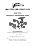
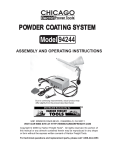
AIR COMPRESSOR
2.5 HP - 8 GALLON
90385
ASSEMBLY AND OPERATING INSTRUCTIONS
3491 MISSION OAKS BLVD., CAMARILLO, CA 93011
VISIT OUR WEB SITE AT HTTP://WWW.HARBORFREIGHT.COM
Copyright© 2003 by Harbor Freight Tools®. All rights reserved. No portion of this
manual or any artwork contained herein may be reproduced in any shape or
form without the express written consent of Harbor Freight Tools.
For technical questions and replacement parts, please call 1-800-444-3353
SPECIFICATIONS
Item
Power Consumption
Motor
Pump
Tank
Air Outlet Size
Pressure Gauge
SCFM
Features
Weight
Description
120 VAC, 60 Hz
2.5 HP (rated), 3400 RPM; 2 capacitor motor
Single stage, oil lubrication
8 gallon capacity; Cut-in pressure: 90 PSI, Cutout pressure: 120 PSI
1/4 Inch - 18 NPT
0 ~ 200 PSI (CSA approved)
4.5 SCFM @ 115 PSI, 5.6 SCFM @ 90 PSI, 6.2
SCFM @70 PSI, and 7.25 SCFM @ 40 PSI
Overload protection
Clear view oil window
65 lbs.
4 STL
THIS COMPRESSOR MUST BE OPERATED ON A MINIMUM 15 AMP CIRCUIT.
SAVE THIS MANUAL
You will need the manual for the safety warnings and precautions, assembly instructions,
operating and maintenance procedures, parts list and diagram. Keep your invoice with this
manual. Write the invoice number on the inside of the front cover. Keep the manual and
invoice in a safe and dry place for future reference.
GENERAL SAFETY RULES
WARNING!
READ AND UNDERSTAND ALL INSTRUCTIONS. Failure to follow all instructions listed below may result in electric shock, fire, and/or serious injury.
SAVE THESE INSTRUCTIONS
Work Area
1.
Keep your work area clean and well lit. Cluttered benches and dark areas invite
accidents.
2.
Do not operate power tools in explosive atmospheres, such as in the presence
of flammable liquids, gases, or dust. Power tools create sparks which may ignite
the dust or fumes.
3.
Keep bystanders, children, animals and visitors away while operating a power
tool.
Distractions can cause you to lose control. Protect others in the work area from
debris such as chips and sparks. Provide barriers or shields as needed.
REV 12/03;07/04;11/04
SKU 90385
For technical questions, please call 1-800-444-3353.
Page 2
Electrical Safety
4.
Avoid body contact with grounded surfaces such as pipes, radiators, ranges,
and refrigerators. There is an increased risk of electric shock if your body is
grounded.
5.
Do not expose power tools to rain or wet conditions. Water entering a power tool
will increase the risk of electric shock.
6.
Grounded tools must be plugged into an outlet properly installed and grounded
in accordance with all codes and ordinances. Never remove the grounding
prong or modify the plug in any way. Do not use any adapter plugs. Check with
a qualified electrician if you are in doubt as to whether the outlet is properly
grounded. If the tools should electrically malfunction or break down, grounding
provides a low resistance path to carry electricity away from the user.
7.
Double insulated tools are equipped with a polarized plug (one blade is wider
than the other). This plug will fit in a polarized outlet only one way. If the plug
does not fit fully in the outlet, reverse the plug. If it still does not fit, contact a
qualified electrician to install a polarized outlet. Do not change the plug in any
way. Double insulation
eliminates the need for the three wire grounded power
cord and grounded power supply system.
8.
Do not abuse the Power Cord. Never use the Power Cord to carry the tools or
pull the Plug from an outlet. Keep the Power Cord away from heat, oil, sharp
edges, or moving parts. Replace damaged Power Cords immediately. Damaged
Power Cords increase the risk of electric shock.
Personal Safety
9.
Stay alert. Watch what you are doing, and use common sense when operating a
power tool. Do not use a power tool while tired or under the influence of drugs,
alcohol, or medication. A moment of inattention while operating power tools may
result in serious personal injury.
10.
Dress properly. Do not wear loose clothing or jewelry. Contain long hair. Keep
your hair, clothing, and gloves away from moving parts. Loose clothes, jewelry, or
long hair can be caught in moving parts.
11.
Avoid accidental starting. Be sure the Power Switch is off before plugging in.
Carrying power tools with your finger on the Power Switch, or plugging in power tools
with the Power Switch on, invites accidents.
12.
Remove adjusting keys or wrenches before turning the power tool on. A wrench
or a key that is left attached to a rotating part of the power tool may result in personal
injury.
13.
Do not overreach. Keep proper footing and balance at all times. Proper footing
and balance enables better control of the power tool in unexpected situations.
SKU 90385
For technical questions, please call 1-800-444-3353.
Page 3
14.
Use safety equipment. Always wear eye protection. Dust mask, nonskid safety
shoes, hard hat, or hearing protection must be used for appropriate conditions.
Tool Use and Care
15.
Use clamps (not included) or other practical ways to secure and support the
workpiece to a stable platform. Holding the work by hand or against your body is
unstable and may lead to loss of control.
16.
Do not force the tool. Use the correct tool for your application. The correct tool
will do the job better and safer at the rate for which it is designed.
17.
Do not use the power tool if the Power Switch does not turn it on or off. Any tool
that cannot be controlled with the Power Switch is dangerous and must be replaced.
18.
Disconnect the Power Cord Plug from the power source before making any
adjustments, changing accessories, or storing the tool. Such preventive safety
measures reduce the risk of starting the tool accidentally.
19.
Store idle tools out of reach of children and other untrained persons. Tools are
dangerous in the hands of untrained users.
20.
Maintain tools with care. Keep cutting tools sharp and clean. Properly
maintained tools with a sharp cutting edge are less likely to bind and are easier to
control. Do not use a damaged tool. Tag damaged tools “Do not use” until repaired.
21.
Check for misalignment or binding of moving parts, breakage of parts, and any
other condition that may affect the tool’s operation. If damaged, have the tool
serviced before using. Many accidents are caused by poorly maintained tools.
22.
Use only accessories that are recommended by the manufacturer for your
model. Accessories that may be suitable for one tool may become hazardous when
used on another tool.
Service
23.
Tool service must be performed only by qualified repair personnel. Service or
maintenance performed by unqualified personnel could result in a risk of injury.
24.
When servicing a tool, use only identical replacement parts. Follow instructions
in the “Inspection, Maintenance, And Cleaning” section of this manual. Use of
unauthorized parts or failure to follow maintenance instructions may create a risk of
electric shock or injury.
SKU 90385
For technical questions, please call 1-800-444-3353.
Page 4
SPECIFIC SAFETY RULES FOR THIS PRODUCT
1.
Maintain labels and nameplates on the Air Compressor. These carry important
information. If unreadable or missing, contact Harbor Freight Tools for a replacement.
2.
Maintain a safe working environment. Keep the work area well lit. Make sure there
is adequate surrounding workspace. Always keep the work area free of obstructions,
grease, oil, trash, and other debris. Do not use a power tool in areas near flammable
chemicals, dusts, and vapors. Do not use this product in a damp or wet location.
3.
Avoid unintentional starting. Make sure you are prepared to begin work before
turning on the Air Compressor.
4.
Do not force the Air Compressor. This tool will do the work better and safer at the
pressure and capacity for which it was designed.
5.
Always unplug the Air Compressor from its electrical outlet before performing
and inspection, maintenance, or cleaning procedures.
6.
WARNING! Some dust created by power sanding, sawing, grinding, drilling, and
other construction activities, contain chemicals known (to the State of California) to
cause cancer, birth defects or other reproductive harm. Some examples of these
chemicals are: lead from lead-based paints, crystalline silica from bricks and cement
or other masonry products, arsenic and chromium from chemically treated lumber.
Your risk from these exposures varies, depending on how often you do this type of
work. To reduce your exposure to these chemicals: work in a well ventilated area, and
work with approved safety equipment, such as those dust masks that are specially
designed to filter out microscopic particles. (California Health & Safety Code §
25249.5, et seq.)
7.
WARNING! People with pacemakers should consult their physician(s) before
using this product. Operation of electrical equipment in close proximity to a heart
pacemaker could cause interference or failure of the pacemaker.
8.
Never leave the air compressor unattended while running. Turn power off if you
have to leave the mixer.
9.
Before each use, check all nuts, bolts, and screws for tightness. Vibration may
cause these to loosen.
10.
Always connect the Line Cord to a Ground Fault Circuit Interrupter (GFCI)
protected electrical outlet. Always use a 115V electrical source (+/- 10%
(1)
maximum variation).
11.
Drain compressor every day. Do not allow moisture to build up inside the
compressor. Do not allow compressor to sit pressurized for longer than one hour.
12.
Make sure all equipment is rated to the appropriate capacity. Adjust the output air
pressure to the tool’s operating capacity.
13.
Avoid body injury. Never direct the air outlet at persons or animals.
REV 11/04
SKU 90385
For technical questions, please call 1-800-444-3353.
Page 5
GROUNDING
WARNING!
Improperly connecting the grounding wire can result in the risk of electric
shock. Check with a qualfified electrician if you are in doubt as to whether the
outlet is properly grounded. Do not modify the power cord plug provided with
the tool. Never remove the grounding prong from the plug. Do not use the tool if
the power cord or plug is damaged. If damaged, have it repaired by a service
facility before use. If the plug will not fit the outlet, have a proper outlet installed
by a qualified electrician.
Grounded Tools: Tools with Three Prong Plugs
1.
Tools marked with “Grounding Required” have a three wire cord and three prong
grounding plug. The plug must be connected to a properly grounded outlet. If the tool
should electrically malfunction or break down, grounding provides a low resistance
path to carry electricity away from the user, reducing the risk of electric shock. (See
Figure A.)
2.
The grounding prong in the plug is connected through the green wire inside the cord
to the grounding system in the tool. The green wire in the cord must be the only wire
connected to the tool’s grounding system and must never be attached to an
electrically “live” terminal. (See Figure A.)
3.
Your tool must be plugged into an appropriate outlet, properly installed and grounded
in accordance with all codes and ordinances. The plug and outlet should look like
those in the following illustration. (See Figure A.)
Figure A
Figure B
Double Insulated Tools: Tools with Two Prong Plugs
4.
Tools marked “Double Insulated” do not require grounding. They have a special
double insulation system which satisfies OSHA requirements and complies with the
applicable standards of Underwriters Laboratories, Inc., the Canadian Standard
Association, and the National Electrical Code. (See Figure B on page 6.)
5.
Double insulated tools may be used in either of the 120 volt outlets shown in the
preceding illustration. (See Figure B on page 6.)
SKU 90385
For technical questions, please call 1-800-444-3353.
Page 6
SYMBOLOGY
Table B
UNPACKING
When unpacking, check to make sure that all the parts are included. Refer to the Assembly
section, and the Assembly Drawing and Parts List at the end of this manual.
If any parts are missing or broken, please call Harbor Freight Tools at the number on the cover
of this manual as soon as possible.
In addition, this unit is packed with a rubber block to help prevent damage to the Motor Cover
(82) during shipment, shown below.
This block should be removed BEFORE use of this compressor, it can interfere with
proper operation. It may be set aside for additional shipping purposes, if desired.
REV 05/05
SKU 90385
For technical questions, please call 1-800-444-3353.
Page 7
ASSEMBLY INSTRUCTIONS
Warning: Fill compressor with oil before using; running without oil, or with low oil voids
warranty. Do not plug in the Air Compressor until you are ready to use it, as set forth
below.
Adding Oil
1.
Unscrew (do not pull) the Oil Plug (79). (See Figure C.)
2.
Check the level of the oil by viewing the Oil Leveler
(72) window (below the Oil Plug).
Note: Fill the oil tank with approximately 25 ounces of oil.
3.
Add 30-weight, non-detergent oil through the fill hole
as necessary, but do not overfill. Screw in the Oil Plug,
being careful not to strip the plastic threads.
(79)
Figure C
Hose Connections
1.
Close the Air Control Valve (69), right or left.
2.
Connect the high pressure air hose to the air outlet.
The outlet is 1/4” NPT. For easy connection or removal, a quick coupler (not supplied)
should be installed on the end of the outlet.
To extend the life of your air tools, it is recommended to install an oiler and water filter
in series with the air output line of the Air Compressor as shown below.
Figure D
3.
Connect the high pressure air hose to the air tool.
4.
Turn the Air Control Valve to the middle position to allow the air to pass.
Warning: Do not remove the factory sealed Air Control Valve (69); removal voids warranty.
Air Filter
If not already attached, mount the Air Filter (85) to the Cylinder Head (2) before using the
air compressor.
REV 04/04
SKU 90385
For technical questions, please call 1-800-444-3353.
Page 8
OPERATING INSTRUCTIONS
Turning Compressor On
1.
Plug the power cord into an electrical outlet with a grounding prong.
2.
Pull up on the Auto/Off Pressure Switch (66) to turn on. Push down on the Switch to
shut off.
3.
Allow the Tank to fill to 80 PSI before using.
With the Air Compressor turned on, operation is automatic and under the control of
the internal pressure switch.
Auto / Off Switch
Output Pressure Adjuster
Tank Pressure Gauge
Air Control Valve
Output Pressure Gauge
NOTE: Actual product design may
vary slightly from that shown.
Figure E
Adjusting Pressure Switch
Caution: The internal pressure switch is adjustable but changes to the pressure levels
are not recommended; any change to the automatic On/Off pressure levels will cause
additional stress on the motor which may result in shortened motor life.
Using the Pressure Relief Valve
Figure F
The Pressure Relief Valve (Figure F) is used when decompression is needed quickly and efficiently.
1.
Press the Auto/Off Pressure Switch (66) down to turn
power off.
(1)
2.
Pull on the Pressure Relief Valve (67) ring to release
pressure.
3.
When all pressure is released, close the valve again.
Pressure Relief
Valve
SKU 90385
For technical questions, please call 1-800-444-3353.
REV 04/05
Page 9
Empty Air and Condensation
The water Spill Valve (59) is located underneath the Air Tank. It must be used daily to release all trapped moisture through this valve. It will also get rid of any condensation that
may cause tank corrosion.
Warning: Do not open the water Spill Valve (59) so that more than four threads are
showing.
1.
Push down on the Auto/Off Pressure Switch (66) to turn the compressor off.
2.
Unscrew the water Spill Valve (59) two to three turns.
INSPECTION, MAINTENANCE, AND CLEANING
1.
WARNING! Make sure the Power Switch of the Air Compressor is in its “OFF”
position and that the tool is unplugged from its electrical outlet before performing any
inspection, maintenance, or cleaning procedures.
2.
Before each use, inspect the general condition of the Air Compressor. Check for
loose screws, misalignment or binding of moving parts, cracked or broken parts,
damaged electrical wiring, and any other condition that may affect its safe operation.
If abnormal noise or vibration occurs, have the problem corrected before further use.
Do not use damaged equipment.
3.
Check compressor oil level daily. Fill if necessary with 30-weight, non-detergent oil.
4.
Purge the Air Tank daily of all air and condensation to prevent corrosion.
5.
Store the Air Compressor in a clean and dry location.
6.
Check all air fittings for leaks before using.
PLEASE READ THE FOLLOWING CAREFULLY
THE MANUFACTURER AND/OR DISTRIBUTOR HAS PROVIDED THE PARTS DIAGRAM IN THIS
MANUAL AS A REFERENCE TOOL ONLY. NEITHER THE MANUFACTURER NOR DISTRIBUTOR MAKES ANY REPRESENTATION OR WARRANTY OF ANY KIND TO THE BUYER THAT
HE OR SHE IS QUALIFIED TO MAKE ANY REPAIRS TO THE PRODUCT OR THAT HE OR SHE
IS QUALIFIED TO REPLACE ANY PARTS OF THE PRODUCT. IN FACT, THE MANUFACTURER
AND/OR DISTRIBUTOR EXPRESSLY STATES THAT ALL REPAIRS AND PARTS REPLACEMENTS SHOULD BE UNDERTAKEN BY CERTIFIED AND LICENSED TECHNICIANS AND NOT
BY THE BUYER. THE BUYER ASSUMES ALL RISK AND LIABILITY ARISING OUT OF HIS OR
HER REPAIRS TO THE ORIGINAL PRODUCT OR REPLACEMENT PARTS THERETO, OR ARISING OUT OF HIS OR HER INSTALLATION OF REPLACEMENT PARTS THERETO.
SKU 90385
For technical questions, please call 1-800-444-3353.
Page 10
PARTS LIST
Part #
1
2
3
4A
4B
4C
4D
5
6
7
8
9
10A
10B
11
12
13
14
15
16
17
18
19
20
21
22
23
24
25
26
27
29
30
31
34
35
36A
36B
37
38
39
40
40A
41A
41B
41C
Description
BOLT
CYLINDER HEAD
CYLINDER HEAD WASHER
BOLT
EXHAUSE VALVE PLATE SPACING
EXHAUSE VALVE PLATE
VALVE SEAT
COLUMN PIN
INLET VALVE PLATE
CYLINDER UP WASHER
CYLINDER
CYLINDER DOWN WASHER
PISTON AIR RING
PISTON OIL RING
RETAINING RING IN HOLE
PISTON
PISTON PIN
CONNECT ROD
CRANKCASE
CRANKSHAFT
IN-SIX ANGLE BOLT
RUBBER WASHER
O RING
BOLT
STARTING CAPACITOR
RUNNING CAPACITOR
NUT
SAW WASHER
FLAT WASHER
CONNECTOR
NYLON BAND
BOLT
OVER-LOAD PROTECTOR BRACKET
OVER-LOAD PROTECTOR
SHAFT OIL SEAL
BEARING
MOTOR STATOR ASSEMBLY
MOTOR ROTOR ASSEMBLY
BEARING
WAVE WASHER
MOTOR BACK COVER
BOLT
TIGHTER WASHER
CENTRIFUGAL SWITCH SEAT
CENTRIFUGAL SWITCH BODY
BOLT
Qty.
4
1
1
2
1
1
1
2
1
1
1
1
2
1
2
1
1
1
1
1
1
4
1
1
1
1
2
2
2
2
2
2
1
1
1
1
1
1
1
1
1
1
3
1
1
1
Part #
42
43
44
45
46
47
48
49
50
51
52
53A
53B
54
55
56A
56B
57
58A
58B
59
60
61
62
63
64
65
66
67
68
69
70
71
72
72A
73
74
75
76
79
80
81
82
83
84
85
Description
BOLT
CENTRIFUGAL SWITCH SEAT WASHER
CENTRIFUGAL SWITCH COVER
BOLT
FAN
RETAINING RING IN SHAFT
BOLT
BOLT
TANK
FLAT WASHER
NUT
WHEEL
WHEEL COVER
RETAINING RING IN SHAFT
EXHAUST ELBOW
EXHAUST COPPER TUBE
EXHAUST BOLT
PRESSURE RELIEF VALVE
UNLOAD PIPE NUT
UNLOAD PIPE ASSY.
UNLOAD WATER VALVE
BOLT
RUBBER FOOT PAD
FLAT WASHER
BOLT
ELE. CABLE
PRESSURE GAUGE
PRESSURE SWITCH
PRESSURE RELIEF VALVE
NIPPER
AIR CONTROL VALVE
PRESSURE VALVE
PRESSURE GAUGE
OIL LEVELER
OIL LEVELER SEAL
BOLT
SPRING WASHER
CRANKCASE FROM COVER
CRANKCASE RUBBER SEAL
OIL PLUG
HANDLE
BOLT
MOTOR COVER
BOLT
BOLT
AIR FILLER
Qty.
2
2
1
4
1
2
4
4
1
4
4
2
2
2
1
1
2
1
1
1
1
1
1
1
1
1
1
1
1
1
1
1
1
1
1
1
1
1
1
1
1
4
1
2
2
1
NOTE: Some parts are listed and shown for illustration purposes only and are not available
individually as replacement parts.
SKU 90385
For technical questions, please call 1-800-444-3353.
Page 11
ASSEMBLY DRAWING
SKU 90385
For technical questions, please call 1-800-444-3353.
Page 12