1
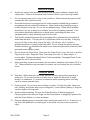
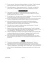
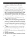
HAMMER DRILL - 1/2 INCH
VARIABLE SPEED - REVERSIBLE
45338
ASSEMBLY AND OPERATING INSTRUCTIONS
3491 MISSION OAKS BLVD., CAMARILLO, CA 93011
VISIT OUR WEB SITE AT HTTP://WWW.HARBORFREIGHT.COM
Copyright © 2003 by Harbor Freight Tools®. All rights reserved. No portion of
this manual or any artwork contained herein may be reproduced in any shape
or form without the express written consent of Harbor Freight Tools.
For technical questions and replacement parts, please call 1-800-444-3353
SPECIFICATIONS
Ite m
P o w e r C o n s u m p tio n
M o to r
C h u c k C a p a c ity
C h u c k T h re a d
Speed
S w itc h
P o w e r C o rd
W e ig h t
F e a tu re s
D e s c rip tio n
1 2 0 V A C , 6 0 H z , s in g le p h a s e , 6 .3 a m p s (lo a d ),
7 5 0 w a tts
D o u b le in s u la te d
3 /6 4 to 1 /2 in c h , p lu s k e y c h u c k
1 /2 " - 2 0 U N F
0 ~ 2 8 0 0 R P M (n o lo a d ); 0 ~ 4 2 ,0 0 0 B P M
E le c tro n ic v a ria b le s p e e d trig g e r, fo rw a rd a n d
re v e rs e ; c o n tin u o u s ru n trig g e r lo c k ; m a x im u m
speed set
6 fe e t lo n g , 1 8 A W G /2 C , 2 -p ro n g p o la riz e d p lu g ,
U L lis te d
4 .9 lb s .
- H ig h Im p a c t H o u s in g
- S id e g rip h a n d le
- B e lt h o o k
- D e p th g a u g e
- R e m o v a b le c h u c k
- Id e a l fo r h a rd m a te ria ls : c o n c re te , m a rb le ,
a n d s te e l
E194601
SAVE THIS MANUAL
You will need the manual for the safety warnings and precautions, assembly instructions,
operating and maintenance procedures, parts list and diagram. Keep your invoice with this
manual. Write the invoice number on the inside of the front cover. Keep the manual and
invoice in a safe and dry place for future reference.
GENERAL SAFETY RULES
WARNING!
READ AND UNDERSTAND ALL INSTRUCTIONS. Failure to follow all instructions listed below may result in electric shock, fire, and/or serious injury.
SAVE THESE INSTRUCTIONS
Work Area
1.
Keep your work area clean and well lit. Cluttered benches and dark areas invite
accidents.
2.
Do not operate power tools in explosive atmospheres, such as in the presence of
flammable liquids, gases, or dust. Power tools create sparks which may ignite the
dust or fumes.
3.
Keep bystanders, children, and visitors away while operating a power tool.
Distractions can cause you to lose control. Protect others in the work area from
debris such as chips and sparks. Provide barriers or shields as needed.
SKU 45338
Page 2
Electrical Safety
4.
Avoid body contact with grounded surfaces such as pipes, radiators, ranges, and
refrigerators. There is an increased risk of electric shock if your body is grounded.
5.
Do not expose power tools to rain or wet conditions. Water entering a power tool will
increase the risk of electric shock.
6.
Grounded tools must be plugged into an outlet properly installed and grounded in
accordance with all codes and ordinances. Never remove the grounding prong or
modify the plug in any way. Do not use any adapter plugs. Check with a qualified
electrician if you are in doubt as to whether the outlet is properly grounded. If the
tools should electrically malfunction or break down, grounding provides a low
resistance path to carry electricity away from the user.
7.
This Double insulated Hammer Drill is equipped with a polarized plug (one blade is
wider than the other). This plug will fit in a polarized outlet only one way. If the plug
does not fit fully in the outlet, reverse the plug. If it still does not fit, contact a
qualified electrician to install a polarized outlet. Do not change the plug in any way.
Double insulation
eliminates the need for the three wire grounded power cord and
grounded power supply system.
8.
Do not abuse the Power Cord. Never use the Power Cord to carry the tools or pull the
Plug from an outlet. Keep the Power Cord away from heat, oil, sharp edges, or
moving parts. Replace damaged Power Cords immediately. Damaged Power Cords
increase the risk of electric shock.
9.
When operating a power tool outside, use an outdoor extension cord marked “W-A” or
“W”. These extension cords are rated for outdoor use, and reduce the risk of electric
shock.
Personal Safety
10.
Stay alert. Watch what you are doing, and use common sense when operating a
power tool. Do not use a power tool while tired or under the influence of drugs,
alcohol, or medication. A moment of inattention while operating power tools may
result in serious personal injury.
11.
Dress properly. Do not wear loose clothing or jewelry. Contain long hair. Keep your
hair, clothing, and gloves away from moving parts. Loose clothes, jewelry, or long hair
can be caught in moving parts.
12.
Avoid accidental starting. Be sure the Power Switch is off before plugging in.
Carrying power tools with your finger on the Power Switch, or plugging in power tools
with the Power Switch on, invites accidents.
13.
Remove adjusting keys or wrenches before turning the power tool on. A wrench or a
key that is left attached to a rotating part of the power tool may result in personal
injury.
SKU 45338
Page 3
14.
Do not overreach. Keep proper footing and balance at all times. Proper footing and
balance enables better control of the power tool in unexpected situations.
15.
Use safety equipment. Always wear eye protection. Dust mask, non-skid safety
shoes, hard hat, or hearing protection must be used for appropriate conditions.
Tool Use and Care
16.
Use clamps (not included) or other practical ways to secure and support the
workpiece to a stable platform. Holding the work by hand or against your body is
unstable and may lead to loss of control.
17.
Do not force the tool. Use the correct tool for your application. The correct tool will do
the job better and safer at the rate for which it is designed.
18.
Do not use the power tool if the Power Switch does not turn it on or off. Any tool that
cannot be controlled with the Power Switch is dangerous and must be replaced.
19.
Disconnect the Power Cord Plug from the power source before making any
adjustments, changing accessories, or storing the tool. Such preventive safety
measures reduce the risk of starting the tool accidentally.
20.
Store idle tools out of reach of children and other untrained persons. Tools are
dangerous in the hands of untrained users.
21.
Maintain tools with care. Keep cutting tools sharp and clean. Properly maintained
tools with a sharp cutting edge are less likely to bind and are easier to control. Do not
use a damaged tool. Tag damaged tools “Do not use” until repaired.
22.
Check for misalignment or binding of moving parts, breakage of parts, and any other
condition that may affect the tool’s operation. If damaged, have the tool serviced
before using. Many accidents are caused by poorly maintained tools.
23.
Use only accessories that are recommended by the manufacturer for your model.
Accessories that may be suitable for one tool may become hazardous when used on
another tool.
Service
24.
Tool service must be performed only by qualified repair personnel. Service or
maintenance performed by unqualified personnel could result in a risk of injury.
25.
When servicing a tool, use only identical replacement parts. Follow instructions in the
“Inspection, Maintenance, And Cleaning” section of this manual. Use of unauthorized
parts or failure to follow maintenance instructions may create a risk of electric shock
or injury.
SKU 45338
Page 4
SPECIFIC SAFETY RULES FOR THE HAMMER DRILL
1.
Hold tool by insulated gripping surfaces when performing an operation where
the cutting tools may contact hidden wiring or its own cord. Contact with a
”live” wire will make exposed metal parts of the tool “live” and shock the
operator.
2.
Maintain labels and nameplates on the Hammer Drill. These carry important
information. If unreadable or missing, contact Harbor Freight Tools for a replacement.
3.
Always wear safety impact eye goggles and heavy work gloves when using the
Hammer Drill. Using personal safety devices reduce the risk for injury. Safety impact
eye goggles and heavy work gloves are available from Harbor Freight Tools.
4.
Maintain a safe working environment. Keep the work area well lit. Make sure there is
adequate surrounding workspace. Always keep the work area free of obstructions,
grease, oil, trash, and other debris. Do not use a power tool in areas near flammable
chemicals, dusts, and vapors. Do not use this product in a damp or wet location.
5.
Avoid unintentional starting. Make sure you are prepared to begin work before turning
on the Hammer Drill.
6.
Do not force the Hammer Drill. This tool will do the work better and safer at the speed
and capacity for which it was designed.
7.
Always unplug the Hammer Drill from its electrical outlet before performing and
inspection, maintenance, or cleaning procedures.
8.
WARNING! Some dust created by power sanding, sawing, grinding, drilling, and
other construction activities, contain chemicals known (to the State of California) to
cause cancer, birth defects or other reproductive harm. Some examples of these
chemicals are: lead from lead-based paints, crystalline silica from bricks and cement
or other masonry products, arsenic and chromium from chemically treated lumber.
Your risk from these exposures varies, depending on how often you do this type of
work. To reduce your exposure to these chemicals: work in a well ventilated area, and
work with approved safety equipment, such as those dust masks that are specially
designed to filter out microscopic particles. (California Health & Safety Code 25249.5,
et seq.)
9.
WARNING! People with pacemakers should consult their physician(s) before
using this product. Operation of electrical equipment in close proximity to a heart
(1)cause interference or failure of the pacemaker.
pacemaker could
10.
Never leave the Hammer Drill unattended while running. Turn power off if you have to
leave the Hammer Drill.
11.
Before each use, check all nuts, bolts, and screws for tightness. Vibration may cause
these to loosen.
12.
Keep extension cord away from water.
13.
Always connect the Line Cord to a Ground Fault Circuit Interrupter (GFCI) protected
electrical outlet.
SKU 45338
Page 5
GROUNDING
WARNING!
Improperly connecting the grounding wire can result in the risk of electric
shock. Check with a qualfified electrician if you are in doubt as to whether the
outlet is properly grounded. Do not modify the power cord plug provided with
the tool. Never remove the grounding prong from the plug. Do not use the tool if
the power cord or plug is damaged. If damaged, have it repaired by a service
facility before use. If the plug will not fit the outlet, have a proper outlet installed
by a qualified electrician.
Grounded Tools: Tools with Three Prong Plugs
1.
Tools marked with “Grounding Required” have a three wire cord and three prong
grounding plug. The plug must be connected to a properly grounded outlet. If the tool
should electrically malfunction or break down, grounding provides a low resistance
path to carry electricity away from the user, reducing the risk of electric shock. (See
Figure A.)
2.
The grounding prong in the plug is connected through the green wire inside the cord
to the grounding system in the tool. The green wire in the cord must be the only wire
connected to the tool’s grounding system and must never be attached to an
electrically “live” terminal. (See Figure A.)
3.
Your tool must be plugged into an appropriate outlet, properly installed and grounded
in accordance with all codes and ordinances. The plug and outlet should look like
those in the following illustration. (See Figure A.)
Figure A
Figure B
Double Insulated Tools: Tools with Two Prong Plugs
4.
This tool is double insulated. Tools marked “Double Insulated” do not require
grounding. They have a special double insulation system which satisfies OSHA
requirements and complies with the applicable standards of Underwriters
Laboratories, Inc., the Canadian Standard Association, and the National Electrical
Code. (See Figure B above.)
5.
Double insulated tools may be used in either of the 120 volt outlets shown in the
following illustration. (See Figure B above.)
SKU 45338
Page 6
EXTENSION CORDS
1.
Grounded tools require a three wire extension cord. Double Insulated tools (like this
one) can use either a two or three wire extension cord.
2.
As the distance from the supply outlet increases, you must use a heavier gauge
extension cord. Using extension cords with inadequately sized wire causes a serious
drop in voltage, resulting in loss of power and possible tool damage. (See Table A.)
3.
The smaller the gauge number of the wire, the greater the capacity of the cord. For
example, a 14 gauge cord can carry a higher current than a 16 gauge cord. (See
Table A.)
4.
When using more than one extension cord to make up the total length, make sure
each cord contains at least the minimum wire size required. (See Table A.)
5.
If you are using one extension cord for more than one tool, add the nameplate
amperes and use the sum to determine the required minimum cord size. (See Table
A.)
6.
If you are using an extension cord outdoors, make sure it is marked with the suffix “WA” (“W” in Canada) to indicate it is acceptable for outdoor use.
7.
Make sure your extension cord is properly wired and in good electrical condition.
Always replace a damaged extension cord or have it repaired by a qualified electrician
before using it.
8.
Protect your extension cords from sharp objects, excessive heat, and damp or wet
areas.
Table A
RECO M M ENDED M INIM UM W IRE G AUG E FO R EXTENSIO N CO RDS*
(120 VO LT)
NAM EPLATE
AM PER ES
(At Full Load)
EXTENSIO N CO R D LENG TH
25
50
75
100
150
Feet
Feet
Feet
Feet
Feet
0 – 2.0
18
18
18
18
16
2.1 – 3.4
18
18
18
16
14
3.5 – 5.0
18
18
16
14
12
5.1 – 7.0
18
16
14
12
12
7.1 – 12.0
18
14
12
10
12.1 – 16.0
14
12
10
16.1 – 20.0
12
10
* Based on lim iting the line voltage drop to five volts at 150% of the rated am peres.
SKU 45338
Page 7
SYMBOLOGY
Table B
UNPACKING
When unpacking, check to make sure that all the parts are included. See Figure C. Also
refer to the Assembly section, and the Assembly Drawing and Parts List at the end of this
manual.
Figure C
Chuck (2)
Depth Gauge (502)
Auxiliary Handle (501)
Chuck Key (3)
If any parts are missing or broken, please call Harbor Freight Tools at the number on the
cover of this manual as soon as possible.
SKU 45338
Page 8
ASSEMBLY INSTRUCTIONS
1.
Insert the Auxiliary Handle (501) over the Housing (29) until it rests behind the Chuck
(2). When required for exact depth drilling, insert the Depth Gauge (502) into the
Auxiliary Handle clamp. See Figure D below.
2.
Turn the Forward Handle for left or right-handed use, then securely tighten the wing
nut until Auxiliary Handle cannot move.
Figure D
Housing (29)
Auxiliary Handle (501)
Chuck (2)
Depth Gauge (502)
Wing Nut
OPERATING INSTRUCTIONS
Inserting and Removing Drill and Hammer Bits
The Hammer Drill is equipped with a keyed Chuck (2). Follow these steps to insert a bit.
1.
Insert the Chuck Key (3) into the Chuck (2) and turn counterclockwise to open the
mouth of the Chuck.
2.
Insert the hammer bit or the drill bit (not supplied) all the way into the Chuck.
3.
Turn the Chuck Key clockwise to tighten the Chuck on the bit.
Drill Operation
1.
Plug the Line Cord into an electrical outlet.
2.
Press the Forward/Reverse Switch to correct position for the current job.
See Figure E on the next page.
Right position: drill or fasten (clockwise).
Left position: removing fasteners or freeing bits (counterclockwise).
SKU 45338
Page 9
Figure E
Forward/Reverse Switch
Switch On
Locking Button
Variable Speed Screw
Trigger Switch (24)
3.
Adjust the Variable Speed Screw for the desired (maximum) speed action when the
Switch is pressed.
4.
For precision depth drilling, loosen the Wing Nut securing the Auxiliary Handle (501),
and slide the Depth Gauge (502) down, gauging the depth from the bit tip. Retighten
the Wing Nut again.
5.
Verify that the bit is securely locked in the Chuck (2).
6.
On the top of the Hammer Drill, push the Gear Setting Control to select plain drilling
or hammer drilling.
A symbol for a drill bit indicates plain drilling is selected. If a hammer is shown, it is set
for hammer drilling. See Figure F below.
Figure F
Note: While using the
Hammer Drill, always
use both hands.
Top View
Gear Setting Control
7.
Press (and hold) the trigger Switch (24) to turn the drill on.
This Switch varies the speed depending on how far in it is pressed.
8.
Optionally, after pressing in the trigger Switch, you can press the Switch On Locking
Button to keep the drill running without keeping your finger on the trigger Switch (24).
Use this function when drilling soft materials only. Press the trigger Switch again to
turn it off.
9.
When you are finished drilling, release the trigger Switch to turn the Hammer Drill off.
Caution: Do not drill or hammer hard, brittle materials such as steel or concrete with
the Switch On Locking Button pressed in (ON). If the drill bit catches on the material,
the high torque of the drill will cause the tool body to twist around without stopping.
This violent action could cause injuries to your hands and arms. It could also damage
the Hammer Drill.
SKU 45338
Page 10
INSPECTION, MAINTENANCE, AND CLEANING
Caution! Make sure the Power Switch of the Hammer Drill is in its “OFF” position
and that the tool is unplugged from its electrical outlet before performing any inspection, maintenance, or cleaning procedures.
1.
Before each use, inspect the general condition of the Hammer Drill. Check for loose
screws, misalignment or binding of moving parts, cracked or broken parts, damaged
electrical wiring, and any other condition that may affect its safe operation. If abnormal
noise or vibration occurs, have the problem corrected before further use. Do not use
damaged equipment.
2.
Periodically recheck all nuts, bolts, and screws for tightness.
3.
Keep clean by wiping with a clean, damp cloth. Never use caustic agents to clean
plastic parts.
4.
Store in a clean and dry location when not in use.
5.
Periodically, using a rag and light oil, wipe drill bits and other steel parts of the drill to
keep them from rusting.
6.
Periodically blow out the motor air vents of dust and debris using compressed air.
7.
Over time, if the performance of the tool diminishes, or it stops working completely, it
may be necessary to replace the motor’s Carbon Brush (21). If the Carbon Brush is
only dirty, it can be cleaned with an ink eraser and replaced again.
Replacing or cleaning Carbon Brushes must be completed by a qualified service
technician.
PLEASE READ THE FOLLOWING CAREFULLY
THE MANUFACTURER AND/OR DISTRIBUTOR HAS PROVIDED THE PARTS DIAGRAM IN THIS
MANUAL AS A REFERENCE TOOL ONLY. NEITHER THE MANUFACTURER NOR DISTRIBUTOR
MAKES ANY REPRESENTATION OR WARRANTY OF ANY KIND TO THE BUYER THAT HE OR
SHE IS QUALIFIED TO MAKE ANY REPAIRS TO THE PRODUCT OR THAT HE OR SHE IS
QUALIFIED TO REPLACE ANY PARTS OF THE PRODUCT. IN FACT, THE MANUFACTURER
AND/OR DISTRIBUTOR EXPRESSLY STATES THAT ALL REPAIRS AND PARTS REPLACEMENTS
SHOULD BE UNDERTAKEN BY CERTIFIED AND LICENSED TECHNICIANS AND NOT BY THE
BUYER. THE BUYER ASSUMES ALL RISK AND LIABILITY ARISING OUT OF HIS OR HER
REPAIRS TO THE ORIGINAL PRODUCT OR REPLACEMENT PARTS THERETO, OR ARISING
OUT OF HIS OR HER INSTALLATION OF REPLACEMENT PARTS THERETO.
SKU 45338
Page 11
REV 06/04
PARTS LIST
Item No.
1.
2.
3.
4.
5.
6.
7.
8.
9.
10.
11.
12.
13.
14.
15.
16.
17.
18.
19.
20.
21.
22.
23.
24.
25.
26.
27.
28.
29.
30.
31.
32.
33.
34.
501.
502.
Description
Screw, M6x25
Chuck
Chuck Key
Spindle
Steel Ball, 3
Circle Seal
Ball Bearing
Spring
Gear, Large
Needle Bearing, HK1207
Ratchet
Bearing Holder
Washer
Steel Ball
Ball Bearing, 62900
Armature
Stator
Ball Baring, 80018
Change Knob
Brush Cap
Carbon Brush
Brush Holder
Inductor
Switch
Internal Wire
Condenser
Screw, ST4x14
Cord Clip
Housing, A and B
Rubber Sleeve
Cord
Name Plate
Cushion
Screw, ST4x18
Auxiliary Handle
Depth Gauge
Qty.
1
1
1
1
1
1
1
1
1
1
1
1
1
1
1
1
1
1
1
1
2
2
2
1
6
1
2
1
1
1
1
1
1
8
1
1
NOTE: Some parts are listed and shown for illustration purposes only and are not available individually
as replacement parts.
SKU 45338
Page 12
ASSEMBLY DRAWING
SKU 45338
Page 13