1
Congratulations on your purchase of the new
PocketWizard MultiMAX
digital radio triggering system.
T he PocketWizard MultiMAX is a m icrop roces sor-b ased radio slave s ystem that us es
advan ced digital sig naling to inc reas e trigg ering rang e, reliability, an d rejec tion of radio
noise from other sources. Since it utilizes Transceiver technology, it is both a
transmitter and a receiver all in one. It is the most innovative and advanced wireless
solution in the photographic industry. As a stand-alone unit, the MultiMA X offers
prec ision s pec ial effects fun ctions not available in any wireless triggerin g devic e. It
incorporates integrated Trigger Time Control software, True Trigger Confirmation and
Selec tive Qu ad-T riggerin g, all of wh ich of fer s olutions to p hotograp hic c hallenges that
hind er today’s p hotograp her’s creativity. Un paralleled in featu res an d perf orman ce,
the P ocket W izard M ultiMA X is m ore than jus t a radio slave.
Welcome to Digital Wireless Freedom!
3
FCC & IC Compliance Information
W AR NIN G : Ch anges or mod ifications to this u nit not expres sly app roved by the p arty
resp ons ible for c omp liance c ould void the u ser's authority to operate the eq uipm ent.
NO TE : This equipm ent has been tested and found to comp ly with the limits for a
Class B digital device, pursuant to Part 15 of the FCC R ules. These limits are
des igned to p rovide reason able protec tion agains t harm ful interf erenc e in a resid ential
installation. This equipment generates, uses, and can radiate radio frequency energy
and, if not installed and used in accordance with the instructions, may cause harmful
interference to radio communications.
How ever, there is n o guaran tee that interferen ce w ill not occ ur in a p articu lar
installation. If th is equ ipm ent does cau se h armf ul interfer enc e to radio or television
rec eption , wh ich can be d eterm ined by tur ning the eq uipm ent of f an d on , the u ser is
encouraged to try to correct the interference by one or more of the following measures:
•
•
•
Reor ient or relocate the r eceiving an tenna.
Increase the separation between the equipment and receiver.
Consult the dealer or an experienced radio/TV technician for help.
Th is device comp lies with Part 15 of the FCC rules and also with RS S-210 of Industry
& S cien ce C anad a. O perat ion is su bjec t to the f ollowing tw o con dition s: ( 1) T his
device may not cause harmful interference, and (2) this device must accept any
interference received, including interference that may cause undesired operation.
4
Table of Contents
Icon s U sed in this Man ual . . . . . . . . . . . . . . . . . . . . . . . . . . . . . . . . . . . . . . . . . . . . . . . . 8
Featur es . . . . . . . . . . . . . . . . . . . .
Communication Technology
Bas ic F eatures . . . . . . . . . .
Sp ecial Featu res . . . . . . . . .
.
.
.
.
.
.
.
.
.
.
.
.
.
.
.
.
.
.
.
.
.
.
.
.
.
.
.
.
.
.
.
.
.
.
.
.
.
.
.
.
.
.
.
.
.
.
.
.
.
.
.
.
......................
......................
......................
......................
.
.
.
.
.
.
.
.
.
.
.
.
.
.
.
.
.
.
.
.
.
.
.
.
.9
.9
.9
.9
Parts Des ignation . . . . . . . . . . . . . . . . . . . . . . . . . . . . . . . . . . . . . . . . . . . . . . . . . . . . . . 10
LC D In form ation . . . . . . . . . . . . . . . . . . . . . . . . . . . . . . . . . . . . . . . . . . . . . . . . . . . . . . . 11
C ontro ls . . . . . . . . . . . . . . . . . .
Power Switch . . . .
Keypad . . . . . . . . .
PORT 1 / PORT 2
Status LED . . . . . .
.
.
.
.
.
.
.
.
.
.
.
.
.
.
.
.
.
.
.
.
.
.
.
.
.
.
.
.
.
.
.
.
.
.
.
.
.
.
.
.
.
.
.
.
.
.
.
.
.
.
.
.
.
.
.
.
.
.
.
.
.
.
.
.
.
.
.
.
.
.
.
.
.
.
.
....................
....................
....................
....................
....................
.
.
.
.
.
.
.
.
.
.
.
.
.
.
.
.
.
.
.
.
.
.
.
.
.
.
.
.
.
.
.
.
.
.
.
. 12
. 12
. 12
. 12
. 12
G etting S tarted . . . . . . . . . . . . . . . . . . . . . . . . . . . . . . . . . . . . . . . . . . . . . . . . . . . . . . . . 13
Battery Inf ormation . . . . . . . . . . . . . . . . . . . . . . . . . . . . . . . . . . . . . . . . . . . . . . . . 13
Ins erting B atteries . . . . . . . . . . . . . . . . . . . . . . . . . . . . . . . . . . . . . . . . . . . . 13
Battery Life . . . . . . . . . . . . . . . . . . . . . . . . . . . . . . . . . . . . . . . . . . . . . . . . . 13
Lanyard . . . . . . . . . . . . . . . . . . . . . . . . . . . . . . . . . . . . . . . . . . . . . . . . . . . . . . . . . 14
V E LC R O ® . . . . . . . . . . . . . . . . . . . . . . . . . . . . . . . . . . . . . . . . . . . . . . . . . . . . . . . 14
Care and Maintenance . . . . . . . . . . . . . . . . . . . . . . . . . . . . . . . . . . . . . . . . . . . . . 15
Quick Setup - Basic Radio Slave Operation
.......
Basic Setup for Remote Flash . . . . . . . . . . . . . . . . . . . . . . . . . . . . . . . . . . .
T riggerin g M ultiple Flas hes W ith M ultiple R EC EIV E U nits . . . . . . . . . . . . .
Connecting MultiMAX (set for TRANS MIT mode) to Flash . . . . . . . . . . . . .
.
.
.
.
.
.
.
.
.
.
.
.
. 16
. 16
. 17
. 17
Stan dard R adio O peration . . . . . . . . . . . . . . . . . . . . . . . . . . . . . . . . . . . . . . . . . . . . . . . 18
T rans ceiver C ontrol . . . . . . . . . . . . . . . . . . . . . . . . . . . . . . . . . . . . . . . . . . . . . . . 18
C han nels . . . . . . . . . . . . . . . . . . . . . . . . . . . . . . . . . . . . . . . . . . . . . . . . . . . . . . . 18
Com patibility . . . . . . . . . . . . . . . . . . . . . . . . . . . . . . . . . . . . . . . . . . . . . . . . . . . . . 19
Selective Quad-Triggering (A B C D keys) . . . . . . . . . . . . . . . . . . . . . . . . . . . . . . 20
C lass ic C han nels . . . . . . . . . . . . . . . . . . . . . . . . . . . . . . . . . . . . . . . . . . . . 21
L K ey . . . . . . . . . . . . . . . . . . . . . . . . . . . . . . . . . . . . . . . . . . . . . . . . . . . . . . 21
T rue C onfirm ation . . . . . . . . . . . . . . . . . . . . . . . . . . . . . . . . . . . . . . . . . . . . . . . . . 22
R adio . . . . . . . . . . . . . . . . . . . . . . . . . . . . . . . . . . . . . . . . . . . . . . . . . . . . . 22
O ption al Flas h C onf irm ation C able . . . . . . . . . . . . . . . . . . . . . . . . . . . . . . . 22
5
Men u S ystem . . . . . . . . . . . . . . . . . . .
Navigation . . . . . . . . . . . . . . . . .
LCD C ontrast Adjustment
Num eric Entry . . . . . . . . .
.
.
.
.
.
.
.
.
.
.
.
.
.
.
.
.
.
.
.
.
.
.
.
.
.
.
.
.
.
.
.
.
.
.
.
.
.
.
.
.
.
.
.
.
.
.
.
.
.
.
.
.
Main Menu . . . . . . . . . . .
A: Advanced Menu
B: Basic Settings .
C: Counter Menu .
D: G o Ad vanced . .
D: G o Nor mal . . . .
.
.
.
.
.
.
.
.
.
.
.
.
.
.
.
.
.
.
.
.
.
.
.
.
.
.
.
.
.
.
.
.
.
.
.
.
.
.
.
.
.
.
.
.
.
.
.....................
.....................
.....................
.....................
.
.
.
.
.
.
.
.
.
.
.
.
.
.
.
.
.
.
.
.
.
.
.
.
.
.
.
.
.
.
.
.
.
.
.
.
.
.
.
.
.
.
.
.
.
.
.
.
.
.
.
.
.
.
.
.
.
.
.
.
.
.
.
.
.
.
.
.
.
.
.
.
.
.
.
.
.
.
.
.
.
.
.
.
.
.
.
.
.
.
.............
.............
.............
.............
.............
.............
Basic Settings . . . . . . . . . . . . . . . . .
A : C on tac t T im e . . . . . . . . . .
B: Beep Menu . . . . . . . . . . . .
A: Beep on All . . . . . . .
B: B eep on T rigger . . .
C: B eep on Z ero / Err or
D : Be ep D isab le . . . . .
.
.
.
.
.
.
.
.
.
.
.
.
.
.
.
.
.
.
.
.
.
.
.
.
.
.
.
.
.
.
.
.
.
.
.
.
.
.
.
.
.
.
.
.
.
.
.
.
.
.
.
.
.
.
.
.
.
.
.
.
.
.
.
.
.
.
.
.
.
.
.
.
.
.
.
.
.
.
.
.
.
.
.
.
.
.
.
.
.
.
.
.
.
.
.
.
.
.
.
.
.
.
.
.
.
.
.
.
.
.
.
.
.
.
.
.
.
.
.
.
.
.
.
.
.
.
.
.
.
.
.
.
.
.
.
.
.
.
.
.
.
.
.
.
.
.
.
.
.
.
.
.
.
.
.
.
.
.
.
.
.
.
. 24
. 24
. 24
. 25
.
.
.
.
.
.
.
.
.
.
.
.
.
.
.
.
.
.
.
.
.
.
.
.
.
.
.
.
.
.
. 26
. 26
. 26
. 26
. 26
. 26
...................
...................
...................
...................
...................
...................
...................
.
.
.
.
.
.
.
.
.
.
.
.
.
.
.
.
.
.
.
.
.
.
.
.
.
.
.
.
. 27
. 27
. 29
. 29
. 29
. 29
. 29
Counter Menu . . . . . . . . . . . . . . . . . . . . . . . . . . . . . . . . . . . . . . . . . . . . . . . . . . . . . . . . . 30
A: C ount U p + R eset . . . . . . . . . . . . . . . . . . . . . . . . . . . . . . . . . . . . . . . . . . . . . . 30
B: C ount D own + Res et . . . . . . . . . . . . . . . . . . . . . . . . . . . . . . . . . . . . . . . . . . . . 30
C: C lear / Res et . . . . . . . . . . . . . . . . . . . . . . . . . . . . . . . . . . . . . . . . . . . . . . . . . . 31
D : D isab le . . . . . . . . . . . . . . . . . . . . . . . . . . . . . . . . . . . . . . . . . . . . . . . . . . . . . . . 31
L: Load . . . . . . . . . . . . . . . . . . . . . . . . . . . . . . . . . . . . . . . . . . . . . . . . . . . . . . . . . 31
Advanced Menu . . . . . . . . . . . . . . . . . . . . . . . . . . . . . . . . . . . . . . . . . . . . . . . . . . . . . . . 32
A: Delay Menu - TRANSMITTER . . . . . . . . . . . . . . . . . . . . . . . . . . . . . . . . . . . . . 32
A : R em otes + P O R T 2 . . . . . . . . . . . . . . . . . . . . . . . . . . . . . . . . . . . . . . . . 32
B: R em otes O nly . . . . . . . . . . . . . . . . . . . . . . . . . . . . . . . . . . . . . . . . . . . . . 33
C : R ear C urtain . . . . . . . . . . . . . . . . . . . . . . . . . . . . . . . . . . . . . . . . . . . . . . 33
A: Delay Menu - RECEIVER . . . . . . . . . . . . . . . . . . . . . . . . . . . . . . . . . . . . . . . . 34
A : P O R T 1 + PO R T 2 . . . . . . . . . . . . . . . . . . . . . . . . . . . . . . . . . . . . . . . . 34
B : P O R T 2 . . . . . . . . . . . . . . . . . . . . . . . . . . . . . . . . . . . . . . . . . . . . . . . . . 34
C: E qualize . . . . . . . . . . . . . . . . . . . . . . . . . . . . . . . . . . . . . . . . . . . . . . . . . 35
B: Intervalom eter ( T im e Lap se Photogr aph y) . . . . . . . . . . . . . . . . . . . . . . . . . . . . 36
C: M ultipop . . . . . . . . . . . . . . . . . . . . . . . . . . . . . . . . . . . . . . . . . . . . . . . . . . . . . . 37
D: SpeedCycler - TRANSMITTER . . . . . . . . . . . . . . . . . . . . . . . . . . . . . . . . . . . . 38
D: Fast Mode - RECEIVER . . . . . . . . . . . . . . . . . . . . . . . . . . . . . . . . . . . . . . . . . 39
6
O ther F eatures . . . . . . . . . . . . .
Keypad Lock . . . . . . . . . .
Hig h V oltage Protec tion .
Relay Mode . . . . . . . . . . .
Sof tware V ersion D isplay
.
.
.
.
.
.
.
.
.
.
.
.
.
.
.
.
.
.
.
.
.
.
.
.
.
.
.
.
.
.
.
.
.
.
.
.
.
.
.
.
.
.
.
.
.
.
.
.
.
.
.
.
.
.
.
.
.
.
.
.
.
.
.
.
.
.
.
.
.
.
.
.
.
.
.
.
.
.
.
.
.
.
.
.
.
.
.
.
.
.
.
.
.
.
.
.
.
.
.
.
...............
...............
...............
...............
...............
.
.
.
.
.
.
.
.
.
.
.
.
.
.
.
.
.
.
.
.
.
.
.
.
.
.
.
.
.
.
.
.
.
.
.
. 39
. 39
. 39
. 40
. 40
Applications of Advanced Functions . . . . . . . . . . . . . . . . . . . . . . . . . . . . . . . . . . . . . . . . 41
Self-Timer or Cable Release . . . . . . . . . . . . . . . . . . . . . . . . . . . . . . . . . . . . . . . . . 41
T T L / A uto flas h H elper . . . . . . . . . . . . . . . . . . . . . . . . . . . . . . . . . . . . . . . . . . . . 41
Programmed sequence shooting . . . . . . . . . . . . . . . . . . . . . . . . . . . . . . . . . . . . . 42
Recycle Lockout . . . . . . . . . . . . . . . . . . . . . . . . . . . . . . . . . . . . . . . . . . . . . . . . . . 42
Cam era Eq ualization . . . . . . . . . . . . . . . . . . . . . . . . . . . . . . . . . . . . . . . . . . . . . . . 43
Lag Time Measurement . . . . . . . . . . . . . . . . . . . . . . . . . . . . . . . . . . . . . . . 44
O ne U nit Eq ualization . . . . . . . . . . . . . . . . . . . . . . . . . . . . . . . . . . . . . . . . . 47
T wo U nit Eq ualization . . . . . . . . . . . . . . . . . . . . . . . . . . . . . . . . . . . . . . . . . 47
Eq ualization Adjus tmen ts . . . . . . . . . . . . . . . . . . . . . . . . . . . . . . . . . . . . . . 49
T ech nical In form ation . . . . . . . . . . . . . .
Specifications . . . . . . . . . . . . . . .
Rad io Inform ation . . . . . . . . . . . .
Maximum and Minimum S ettings
Saved Settings . . . . . . . . . . . . . .
.
.
.
.
.
.
.
.
.
.
.
.
.
.
.
.
.
.
.
.
.
.
.
.
.
.
.
.
.
.
.
.
.
.
.
.
.
.
.
.
.
.
.
.
.
.
.
.
.
.
.
.
.
.
.
.
.
.
.
.
.
.
.
.
.
.
.
.
.
.
.
.
.
.
.
.
.
.
.
.
.
.
.
.
.
.
.
.
.
.
.................
.................
.................
.................
.................
.
.
.
.
.
. 50
. 50
. 51
. 52
. 52
Troubleshooting . . . . . . . . . . . . . . . . . .
W hen in d oubt ! . . . . . . . . . . . . .
Reset to Default Factory Settings
Radio Performance . . . . . . . . . . .
.
.
.
.
.
.
.
.
.
.
.
.
.
.
.
.
.
.
.
.
.
.
.
.
.
.
.
.
.
.
.
.
.
.
.
.
.
.
.
.
.
.
.
.
.
.
.
.
.
.
.
.
.
.
.
.
.
.
.
.
....................
....................
....................
....................
.
.
.
.
. 53
. 53
. 53
. 54
T ime C onversion Ch arts . . . . . . . . . . . . . . . . . . . . . . . . . . . . . . . . . . . . . . . . . . . . . . . . . 55
Frac tions to D ecim al . . . . . . . . . . . . . . . . . . . . . . . . . . . . . . . . . . . . . . . . . . 55
Seconds to Minutes and Hours . . . . . . . . . . . . . . . . . . . . . . . . . . . . . . . . . . 55
7
Icons Used in this Manual
N
N
Read the information following this icon. It shows important notes about the
subject being discussed.
L
L
Follow this icon for more detailed information on the subject in another section.
ë
ë
Find valuable tips and techniques with this icon.
Ref er to h tt p: // ww w .p oc k et wiz ar d. com / for updated information.
8
Features
Communication Technology
•
•
•
•
•
Fu ll Digital R adio C omm unic ation
Microprocessor controlled
32 digitally coded channels
Com plex 16 or 2 4 bit c oded s ignal
Selective Quad-Triggering
Basic Features
•
•
•
•
•
•
•
•
•
•
•
•
•
Bu ilt-in hot sh oe
1/4-20 female mounting thread
B u ilt -in A C ad ap ter jac k (1 .8 m m )
Illum inated LC D pan el
Illuminated soft touch keypad
Extended battery life
Sync sp eeds up to 1 /250 with f ocal plane s hutter,1 /500 with leaf s hutter
Fas t Mod e sync s u p to 1/1 000 with c omp atible cam eras an d flas hes
A d ju s tab le c on tac t c los u re tim e
Compatible with PocketWizard Classic, Plus, and MAX
Protects cameras from high sync voltage
Customizable audible beep settings
W eighs less than 5 .5 oun ces with b atteries
Special Features
•
•
•
Transceiver Technology
T rue C onfirm ation
•
Q uad-T riggerin g C onfirm ation on all four z ones
•
Flas h C onfirm ation with O ptional C able on all four z ones
Trigger T ime Controller Software
•
Rear Curtain Sync
•
Prec ision D elays
•
Intervalometer
•
Mu ltipop
•
Lag Time Measurement
•
Mu ltiple Cam era Eq ualization
•
Sp eedC ycler
•
Relay Mode
9
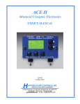
Parts Designation
10
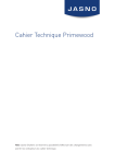
LCD Information
11
Controls
Power Switch
•
T R A N SM IT
•
RECEIVE
•
OFF
U nit is pow ered on in
TR ANS MITT ER (T X) mode
U nit is pow ered on in
REC EIVER (R X) mode
Unit is powered OFF
Power Switch
Keypad
•
A B C D L Selec ts Q uad-T riggerin g Z ones
and Local. Also used in menu
navigation and num eric entry
•
TEST
Triggers MultiMAX. Press to test
operation or to trigg er rem ote units
and/or attac hed c ameras /flash es
•
(Back Light) Illuminates LCD and
keypad. Hold down for key lock
•
~ /M E N U
En ters or exits men u s ystem .
Stores num bers in numeric entry
•
(U p / D own) Selec ts c hann els.
Also used in num eric entry
Keypad
PORT 1 / PORT 2
•
CAM ERA / PORT 1 =
•
Inp ut f rom cam era s ync term inal,
external trigger button, Flash
Confirmation Cable, or other device
•
O utpu t to cam era motor d rive, flash, or
other device
•
FLASH / PORT 2 =
•
O utpu t to flash , cam era motor d rive, or
other device
PORT 1 / PORT 2 / Status LED
Status LED
Displays the following information:
•
Blink ing every few sec onds = pow er on, ready f or trigger
•
Blinking in sync with trigger = normal triggering
•
Stead y =
•
continuously triggered from radio, hot shoe, or PORT 1
•
p er for m in g d elay or con tac t tim e
•
Slow blink every sec ond = perfor min g Intervalom eter or Mu lti-pop fu nc tion
•
Dar k = p ower off or poor battery c ondition
12
Getting Started
Battery Information
The MultiMAX requires two AA size (IEC: LR6)
batteries. T he M ultiMA X will operate norm ally with
Nic kel Metal H ydride (N iMH ), Lithium Ion (Li), N ickel
Cad ium (N iCad ) and A lkaline batteries.
Alkaline batteries are recommended.
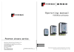
Ins erting B atteries
1.
2.
3.
4.
5.
Set p ower s witch to O FF pos ition
O pen b attery door
Ins ert fres h batteries noting c orrect orien tation
as displayed in battery compartment
Clos e battery door
U se u nit n orm ally
N Er ratic un it beh avior or m alfu nc tion m ay occ ur if
batteries are in serted while the p ower s witch is s et to
either RE CE IVE or T RA NS MIT . Always make sure
the pow er sw itch is set to O FF before c hang ing or
inserting batteries.
Battery Compartment
Battery Life
The MultiMAX displays remaining battery life with a 3 segment battery icon in the
u pp er lef t c or ner of th e L C D :
3
2
1
0
s egm ents disp layed = batteries are fres h/new
s egm ents disp layed = batteries are good
s egm ent dis played = rep lace batteries soon
s egm ents dis played = ins tall fres h/n ew b atteries imm ediately
Battery Ic on
W ith on e set of s tand ard A lkaline b atteries the M ultiM AX will oper ate for app roxim ately
150 hours. This time may vary depending on temperature, battery type, and the
quality of batteries us ed. E xtensive us e of bac k light, s peaker, or extend ed trigg er
con tact tim es w ill cons um e the batteries at a faster r ate.
13
The MultiMAX continually regulates the battery power which gives excellent
perfor man ce th rough out the life of th e batteries. T he un it will continu e to fun ction
normally until the batteries are nearly exhausted.
N T he M ultiM AX voltage reg ulation is very ef fic ient. T here is only a s mall bene fit
when using Lithium batteries. Lithium batteries are designed for the quick burst high
current draw found in cameras and portable flash devices. Expect only a 10 - 20%
longer battery life (approximate) over Alkaline batteries when using Lithium batteries.
ë Examine batteries frequently to prevent damage from leaking battery acid.
Remove batteries from MultiMAX units in the following circumstances to avoid damage
from leaking:
•
•
•
If unit will not be used for a period longer than 2 weeks
Du ring s hipp ing or air travel
In high heat environm ents
Lany ard
A lanyard is inc luded f or hang ing eac h un it convenien tly on a light stan d, tripod , belt,
or other location. If desired, attach the included lanyard to the lanyard loop.
V E LC R O ® Brand Fas teners
V E LC R O ® adhes ive hook and loop f astener s are inc luded w ith the M ultiMA X to
provide a c onvenient m eans of m ounting the un it in a variety of places .
Attac h as des ired being caref ul to not obs cu re con trols or f unc tion. R ecom men ded
mounting locations:
•
•
•
N
14
R ight sid e of th e un it
Lef t sid e of u nit
Below 1/4-20 tripod mount
The battery door is not a recommended mounting location.
Care and M aintenance
To ensure continued reliability, please follow these guidelines:
•
D o n ot s u bjec t u nit s to h ig h m ec h an ic al s h oc k (d o n ot d rop ! )
•
Kee p u nit d ry. D o not im mers e in an y liquid
•
Set power switch to OFF when not in use
•
R em ove us ed b atteries prom ptly
•
Remove batteries for travel or extended storage
•
Clean with s oft dry c loth
•
Operating temperature: above -15/ (5/ F) and below 50/ C (120/ F)
•
Storag e temp erature withou t batteries:
•
above -30/ C (-22/ F)
•
below +85/ C (185/F).
15
Quick Setup - Basic Radio Slave Operation
Basic Setup for Remote Flash
N Turn off all equipment before installing batteries or making connections!
1.
Install 2 AA batteries in each MultiMAX
2.
Connect camera to first MultiMAX:
a.
Slide u nit into cam era hot s hoe
- orb.
Us e sync cab le (inclu ded) to c onnec t cam era’s P C ter min al to
C A M ER A / P O R T 1
3.
Connect flash to second MultiMAX
a.
Use flash cable to connect flash unit’s sync terminal to FLASH / PORT 2
4.
T urn both M ultiMA X un its on
a.
Set power switch on MultiMAX attached to camera to TRAN SMIT m ode
b.
Set power switch on MultiMAX attached to flash to REC EIVE mode
5.
Set both MultiMAX units to same channel and Quad-Triggering zone
a.
Us e to set channel (default is CH: 17)
b.
Us e A B C D L to select Quad-Triggering zones
(default is TRA NSMIT = A B C D L, RECEIVE = A
6.
T urn cam era and f lash on
7.
Press TEST button on M ultiMA X (s et for T RA NS MIT mod e) and releas e.
Confirm remote flash triggers.
You ’re all s et! U se the camera n orm ally.
16
Trig gering M ultiple Flashe s W ith M ultiple RE CE IVE U nits
Multiple remote flash units m ay be triggered in sync w ith each other.
1.
2.
3.
4.
Ins tall batter ies in each add itional M ultiM AX un it
Us e flash cab le to conn ect eac h add itional flash u nit’s s ync term inal to
F LA S H / P O R T 2
Set power switch on each additional MultiMAX unit to RECE IVE mode
Set all Mu ltiMA X un its to s am e ch ann el as T R AN SM IT un it
You ’re all s et! U se the camera n orm ally.
Connecting M ultiM AX (set for TRANSM IT mode) to Flash
A flash c an be connected to a MultiMA X (set for T RANSMIT mode). It will trigger in sync
with th e remote f lash u nits. T his f lash is called the loc al flash and is us ually moun ted
on a cam era brac ket.
1.
2.
Us e a flash cab le to conn ect the f lash u nit’s s ync term inal to FLA SH / PO RT 2 of
the M ultiMA X (s et for T RA NS MIT mod e)
Us e the L key to enable or disable the Local flash
You ’re all s et! U se the camera n orm ally.
L
Using a local flash this way protects the camera from high voltages. See the
Specifications section, Page 50, for more information.
17
Standard Radio Operation
Transceiver Control
T he M ultiMA X operates as either a tran sm itter or a receiver. T o us e the M ultiMA X as
a Transmitter (sending device) set the power switch to TRAN SMIT. To use the
MultiMAX as a Receiver set the power switch to RECEIVE.
L T here is a s pec ial mode th at enables a Mu ltiMA X to autom atically switc h fr om
RE CE IVE to TR AN SM IT then b ack to R EC EIV E w hile triggering a remote c amera.
Read the Relay M ode section, Page 40, for more information.
Ch an ne ls
T he M ultiMA X is a 3 2 c hann el digital radio slave. Eac h M ultiMA X c hann el repres ents
a digital cod e trans mitted on sp ecific Poc ketW izard rad io frequ enc ies. T his en ables
man y photographers to work in th e sam e area. It also enables a photogr apher to
control multiple remote devices (c ameras, flash units, etc).
A M ultiMA X (s et for T RA NS MIT mod e) will trigger an y num ber of M ultiMA X un its (s et
for R EC EIV E m ode) s et to the sam e ch annel. U nits s et to differen t ch annels will not
interfere with each other.
From the m ain sc reen pr ess the keys to change channels.
Som e M ultiM AX featu res are only availab le on h igher c han nels . R efer t o the tab le
below f or f eatu res / chan nels availab ility:
Features
18
Channels 1 - 16
Channels 17 - 32
Dig ital Radio S ignal
X
X
Delay including Rear Curtain Sync
X
X
Intervalometer
X
X
Mu ltipop
X
X
Relay Mode
X
X
Selective Quad-Triggering
X
Confirmation (Radio and Flash)
X
Fast Mode
X
Sp eedC ycler
X
Co mp atibility
MultiMAX channels are compatible with all PocketW izard radio slave products per the
table below:
Digital Radio Mo del
M ultiM AX Co m pa tible Ch an ne ls
Poc ketW izard 10 C han nel C lass ic
1-10
Poc ketW izard 16 C han nel C lass ic
1-16
PocketW izard Plus
1-4
PocketWizard MAX
1-16
17-32 Quad-Triggering or Fast Mode
Sekon ic D igital Rad io Tran sm itter
Module RT-32 (L358, L608, L608 CINE)
1-16
17-32 Quad-Triggering
Sekonic Digital Radio Receiver RR-4
1-4
Sekonic Digital Radio Receiver RR-32
1-16
17-32 Quad-Triggering or Fast Mode
Calu met R adio Eq uipp ed T urb o Filter
1-9
Th e digital radio design of the MultiMA X will enable it to be fully compatible with future
PocketW izard products.
19
Selective Quad-Triggering (A B C D keys)
This powerful feature is used to individually control up
to 4 sets of M ultiMA X un its (s et for R EC EIV E m ode)
on the s ame c hann el. Eac h keypad letter, A B C D
refers to an individual zone. Each zone can be
independently selected or deselected from a MultiMAX
(set for TR AN SM IT m ode).
Follow the steps below to test Quad-Triggering:
1.
Set one MultiMAX to TR ANS MIT mode
2.
Set up to 4 MultiMAX units to RECE IVE mode
(sam e ch annel as T RA NS MIT unit)
3.
Us ing the A B C D L keys set each RECEIVE
unit to a different zone
4.
O n the T RA NS MIT unit us e the A B C D L keys
to select w hic h zon es w ill trigg er. T he zon e is
selected when the letter is displayed on the LCD
sc reen. T he zone is des elected w hen a d ot
appears where the letter would be displayed.
5.
R EC EIVE un it
Ch annel: 17 , Zone: A
Pres s th e T ES T key on the M ultiMA X (s et for
T RA NS MIT mod e) unit to trigg er the s elected
zones
Any number of MultiMAX units (set for RECEIVE
mode) may be set to the same channel and zone, and
will trigger simultaneously. Selective Quad-Triggering
is only available on channels 17 and higher.
20
T R AN SM IT un it
Channel: 17
Zones : A, B , and L ocal
R EC EIVE un it
Ch annel: 17 , Zone: B
C lass ic C han nels
C lass ic c han nels are c om patib le with early
Poc ketW izard m odels an d the P ocketW izard P lus.
Selec tive Q uad -T rigg ering is on ly available in
channels 17 through 32. In channels 1 through 16 the
display will show CLASSIC CHANNEL and zones A B
C D do not app ear. T he A key simply toggles the
remote receivers on or off and is displayed on the
main screen as R. It is not possible to toggle both the
remote ( A key) and the local flash (L key) off at the
sam e time wh en us ing a C LA SS IC C HA NN EL .
Operation on these channels is identical to the
function of the LOCAL / BOTH / REMOT E switch
found on PocketW izard Plus and Classic Transmitters.
T RA NS MIT unit s et to
CLAS SIC CH ANN EL 4
Rem ote and Loc al selected
L Key
O n any c hann el the L key toggles the local flas h on or of f in a M ultiMA X (s et for
TR AN SM IT m ode ).
L See th e Connecting M ultiM AX (set for TRANSM IT mode) to Flash section,
Page 17, for more information.
L T he L key toggles Relay M ode when us ing a M ultiMA X (s et for R EC EIV E m ode).
See th e Relay M ode section, Page 40, for more information.
21
True Confirmation
Bec aus e the M ultiMA X is a tru e trans ceiver it autom atically conf irms triggerin g. It can
perform this on two levels: it confirms the round trip radio signal and can c onfirm
actual flash sync with an optional flash confirmation cable. It does this for all QuadT rigg ering zones on every tr igge r. C onf irm ation is indic ated vis ually on th e m ain
screen and audibly using beep modes.
L
For aud ible conf irmation s ettings see the Beep Menu section, Page 29.
R adio
Rad io conf irmation is disp layed on T RA NS MIT units in the A B C D area of the L CD .
An inverted letter shows an error. A normal letter shows confirmation.
Du ring n ormal op eration the dis play will show selec ted and active A B C D zones not
inverted . C onf irm ation w ill occ ur on every trigg er and only in th e event of an err or will
the zone letters invert.
O ption al Flas h C onf irm ation C able
Using the flash confirmation cable the MultiMAX can confirm flash sync for all four
zones on every trigger.
1.
2.
3.
Attach flash confirmation cable to PORT 1 for each MultiMAX (set for RECEIVE
mod e)
Loc ate the s ens or s o that it c an on ly see th e flas h f rom the c orrec t flas h u nit
Press the TEST button on a MultiMAX (set for TRANS MIT mode) to test flash
confirmation. Correct flash confirmation is displayed on the main screen with a
flash icon to th e right of each z one perf ormin g flas h c onfirm ation. In the event of
an error (either no flash was detected or the radio link was incomplete) the zone
letter and the flash icon will invert
A MultiMAX (set for TRA NSM IT mode) will look for REC EIVE units and confirm the
radio link after each of these operations:
•
•
•
•
•
22
Every trigg er
Pow er on or s witch from RE CE IVE to TR AN SM IT
Channel change
Zone change (including L)
Exiting th e men u s ystem
N
Confirmation can only be performed using MultiMAX units on channels 17 and
higher. PocketW izard Plus, Classic, and the original MAX do not perform
confirmation.
N
True Confirmation is designed to work with one MultiMAX (set for RECEIVE
mod e) per zon e. Mu ltiple RE CE IVE units set to the s ame c hann el and zon e will not
individually confirm and may cause incorrect confirmation errors. If multiple MultiMAX
units (set for RECE IVE mode) on the same channel and zone are a mix of flash and
non-flash confirmation units then accurate flash confirmation will not be reported.
The following table shows how confirmation works in different modes:
M ultiMAX M ode
Radio and Flash Confirmation
A R EC EIV E un it us ing Selec tive
Quad-Triggering
Provides normal radio and / or flash
con firm ation
A RE CEIVE unit set to a Delay mode
W ill not provide con firm ation
A R E C EIV E un it s et to F A ST M O D E
Con firm s on zone A only
A R EC EIV E u nit set to In tervalometer
or Mu ltipop
Provides radio confirmation before
the f irs t interval on ly
23
Menu System
Navigation
Man y functions of the M ultiMA X are acc ess ed throu gh eas y-to-navigate m enus .
Press ~ /M E N U to enter the menu system. Menu items are selected by using the
A B C D L keys.
W hile within th e men us the ~ /M E N U key performs two functions:
•
•
If a menu is displayed, pressing ~ /M E N U return s you to th e main s creen
If a numeric entry is displayed, pressing ~ /M E N U stores the dis played nu mb er
in m emory an d proc eeds to either the next inp ut s creen or the m ain sc reen
depending on mode
ë
In th e next ch apters many of the head ing s w ill be f ollow ed b y ~ /M E N U an d s om e
letter com binations . T hes e are quic k referen ces for the k eys to pres s to get to th at
fun ction f ast.
LCD C ontrast Adjustment
W hile in any m enu, u se th e keys to adju st th e disp lay contras t.
24
Num eric Entry
Several menu items require a number or value to be
entered. Numeric entry is performed with A B C D
and keys. T he A B C D keys each select and
add 1 to a specific digit as follows:
A–
B–
C–
D–
selec ts an d add s 1
selec ts an d add s 1
selec ts an d add s 1
selec ts an d add s 1
to the 4 th digit from the righ t
to the 3 rd digit from the righ t
to the 2 nd digit from the righ t
to the rightm ost d igit
O nc e a digit has been s elected, u se th e keys to
adjust the number. Press and hold for fas ter
entry.
EXAMPLE 1
Num eric Entry
Numbers entered in this fashion are saved when the
~ /M E N U key is pres sed and w ill remain s aved even
after power is turned off. If the unit is powered off
while a numeric entry screen is displayed, the
displayed number will not be saved.
L
T he L key is n ot us ed f or nu meric entry. It is
us ed f or Lag T ime M easu rem ent an d is only
available in certain D elay modes . See the s ection
on Lag Time Measurement, Page 44, for more
information.
ë
To quickly get to the lowest setting press and
release the A key once ( selec ts th e highes t digit)
then p ress and h old the key.
EXAMPLE 2
Num eric Entry
25
Main Menu
From the main screen press ~ /M E N U to enter the
Main Men u. P ress a letter to either proceed to another
menu or perform a function per the list below.
A: Advanced M enu – ~ /M E N U A
Press A to enter the A dvanc ed M enu. T he A dvanc ed
Menu con tains D elay mod es ( inc ludin g R ear C urtain
Sync), Intervalometer, Multipop, and SpeedCycler modes.
Main Menu
G o Ad vanced
B: Basic Settings – ~ /M E N U B
Press B to enter the Basic Settings menu. It contains Contact time and Beep menu.
C: Counter Menu – ~ /M E N U C
Press C to enter the Trigger Counter Menu which contains Counter direction, and
other counter functions: Reset / Clear, Disable, and Load.
D: Go Adv anced – ~ /M E N U D
D: Go Norm al – ~ /M E N U D
Press D to toggle between the last Advanced mode
us ed and Nor mal m ode.
T his f unc tion enables a quic k return to stand ard or
normal operation from an advanced function.
The settings of the advanced function are saved.
Main Menu
G o Nor mal
ë Go Normal is a quick way to get to standard radio slave operation after using
advanced functions and menus. Use this function to “turn off” an advanced mode and
us e the M ultiM AX as a rad io slave on ly.
26
Basic Settings
Press ~ /M E N U B to enter the Basic Settings menu.
Press the corresponding letter for the setting you wish
to adjus t.
A : C o nt ac t T im e – ~ /MENU B A
Basic Settings Menu
Con tact tim e is the leng th of tim e that C AM ER A / P O RT 1 or F LA SH /PO RT 2 outp uts
remain contacted. The default Contact Time of 0.12 is enough to trigger most cam era
motor drives and flashes. Many photographers will never need to adjust this num ber.
N C ontac t tim e is h ow lon g th e intern al sw itch is h eld
clos ed. For exam ple, if the c ontact tim e is s et to 3
sec onds and a c amera m otor drive is attac hed to a
MultiM AX , wh en th e M ultiM AX trigg ers the c am era it
will hold the c ontact f or 3 s econ ds . T his is identic al to
pressing and holding the camera’s trigger button for 3
seconds. The contact time starts as soon as any input
is complete. Input can be from any of the following
sou rces : TEST bu tton is pres sed , hot s hoe is
triggered, or radio trigger is received.
Set C ontact T ime S creen
N
C ontac t tim e is N O T the len gth of tim e a M ultiM AX (s et for T R AN SM IT mo de) w ill
send a radio triggering signal. Contact time affects POR T 1 and POR T 2 only and
does not affect radio trigger transmission. Pressing and holding TEST on a MultiMAX
(set for TRAN SMIT m ode) will continuously send the radio trigger signal and hold the
contact on a MultiMAX (set for RECE IVE) as well as the TR ANS MIT unit. W hen the
TEST button is released each unit’s contact time will then begin.
N
Additional triggers occurring during contact time are ignored. The default contact
t im e is 0 .1 2 s ec on ds w hic h tr ig ger s all c am er as an d f las h un it s. A s hor ter con tac t tim e
allows f or mor e triggers per s econ d bu t may not trig ger s ome m otor driven c ameras
because it’s too fast. The default setting of 0.12 allows for 8 triggers per second. The
maximum of 30 triggers per second can be obtained by setting contact time to 0.01
seconds.
27
For trigg ering rem ote cam eras , a long er c ontac t tim e allows for c ontin uou s r epeatab le
motor d rive triggering (examp le: 5 fram e burs ts every trigger ). It also allows for
con trolled bulb exposu re.
•
Example of Burst Shooting: If a rem ote cam era is c apable of f iring 3 f rames
per s econ d in c ontin uou s m otor drive, then a con tact time of 1 sec ond will
always res ult in this remote c amera trig gering for 3 exp osu res
•
Example of Bulb / Shutter Held Open : Set the c ontact tim e for the d esired
bulb exposure time and set the camera to bulb or B mode. W hen triggered the
s h ut ter will r em ain op en for th e c on tac t tim e
For trig gering a remote f lash c ontact tim e can ac t as a flas h rec ycle lockou t.
•
Example of Flash Recycle Lockout: To guarantee that a flash cannot be
triggered fas ter then its recyc le time, set th e contac t time to be jus t longer than
t he r ec yc le tim e
L
T h is m et hod of flas h rec yc le loc k ou t d oes n ot w or k w it h all f las h sys tem s as s om e
will not recyc le while the s ync c ontact is held. S ee Recycle Lockout in the
Applications of Advanced Functions section, Page 42, for another recycle lockout
method.
L
If you are using Intervalometer or M ultipop modes, read these sections, Page 36
and P age 37 , for inf ormation on thes e mod es and how th ey interact w ith C ontact T ime.
28
B: Beep Menu – ~ /MENU B B
T his m enu c ontrols th e beep f unc tions of a Mu ltiMA X.
Pres s th e corres pond ing letter to set th e desired
func tion of the built-in speaker.
A: Beep on All – ~ /MENU B B A
Mu ltiMA X will beep on all triggering, c onfirm ation
errors , and zer o coun ts as indic ated below as well as
on any key pressed.
Beep Menu
B: B eep on T rigger – ~ /MENU B B B
U nit w ill beep w hen trig ger ed b y TEST button , PO RT 1, a R adio T rigger, or th e Hot
Shoe in the following manner:
Bee p C ha rac teris tic
Indicates
Sin gle Sh ort Beep
Indic ates P roper C onfirm ation
Sin gle Long Beep
Indic ates T rigger E rror
Sin gle Ver y Shor t Beep
W hen an y Key is p ress ed
C: B eep on Z ero / Err or – ~ /MENU B B C
T he M ultiM AX un it will not b eep on norm al trigg ering . T he M ultiM AX will beep only
when the cou nter reac hes zero and on c onfirm ation errors in the followin g m anner:
Bee p C ha rac teris tic
Indicates
Sin gle Long Beep
Indicates Trigger Confirmation error or remote MultiMAX
(unit set for RECEIVE m ode) has reached zero count
Dou ble Long Beep
Indicates MultiMAX has reached zero count
Sin gle Sh ort Beep
An y Key is p ress ed excep t TEST
L
A M ultiMA X (s et for R EC EIV E m ode) s et to Beep on Zer o / Error or set to Beep on
All will indicate a c onfirm ation error if the u nit is als o set to c ount d own an d the c ounter
reach es zero. S ee the Counter section, Page 30, for more information.
D : Be ep D isab le – ~ /MENU B B
Turns off all beep functions. Unit will not beep.
29
Counter Menu
Press ~ /M E N U C enter the Counter Menu. This menu
controls the counter functions of the MultiMAX. The
cou nter c an s how th e total num ber of trig gers . It can
also c oun t up or dow n f rom a set valu e. C oun t is
incr emen ted on every trigger from any sou rce:
PO RT 1, TEST button , Hot S hoe, or R adio T rigger.
Counter Menu
A: C ount U p + R eset – ~ /M E N U C A
Count is set to COU NT UP (example: 0,1,2,3,...) and
the c ounter is reset to 0. T he m ain sc reen will dis play
COUNT
m: 0.
B: C ount D own + Res et – ~ /M E N U C B
Cou nt direc tion is s et to DO W N ( example: 1 0,9,8 ,7,...)
and the counter is reset to the load counter value. The
main s cr een will d isp lay C O U N T
(XXXX = load value)
ë
T RA NS MIT unit s et to
C ou nt U p
o: XXXX
The count down function could be used to indicate the number of remaining
fram es f or a remote c amera.
30
C: C lear / Res et – ~ /M E N U C C
Cou nt direc tion is not c hang ed. C ounter is reset to 0 if cou nt direc tion is s et to up, or
the c oun ter is res et to the load value if c oun t direc tion is set to dow n. If the c oun ter is
disab led, then th is fu nc tion will enable the c ounter u sing the last c ount d irection s et.
The Counter is cleared and reset in this fashion when the unit is powered down.
ë Us e ~ C C as an eas y to remem ber qu ick key c omb ination for f ast c ounter res et.
D : D isab le – ~ /M E N U C D
Counter is disabled and is not displayed on the main screen. W hile disabled the
cou nter does not cou nt.
L: Load – ~ /M E N U C L
Enables custom setting of the load count value
(des ired nu mb er to start th e coun t from , whic h is th en
loaded into the MultiMAX computer memory). The
def ault value is 3 6. M aximu m value for the c oun ter is
9999.
Loading a coun ter value while the c ounter is enabled
will set the main screen count to that value and
cou nting will contin ue in the las t direction set
(UP or DO W N).
Load C ounter S creen
N
T he load c ounter value is sh ared with the Intervalometer and M ultipop
functions. Setting a count in either of these functions also sets the load count value
for nor mal c ounter op eration.
31
Advanced Menu
Press ~ /M E N U A to enter the A dvanced Me nu . T his
menu contains the advanced functions of the
MultiMAX. Precision timing and sequencing
operations are available in this menu.
L
Press ~ /M E N U D to cancel advanced functions
and return to normal mode. See the section on
D:Go Adv anced and D:Go Norm al, Pag e 26..
R EC EIVE un it
Advanced Menu
A: Delay Menu - TRANSMITTER – ~ /M E N U A A
En ters th e delay menu for M ultiMA X un its (s et for
T RA NS MIT mod e).
L
Delay menus, with the exception of Rear Curtain,
require n um eric entr y. See the Num eric Entry section,
Page 25.
T R AN SM IT un it
Advanced Menu
ë
All delay screens (numeric entry or rear curtain)
are ins tantly ac tive and trigg ering can occ ur w hile
thes e sc reens are disp layed. A value dis played on
thes e sc reens will be us ed im med iately on trigger.
T his is us eful f or fine tu ning a delay or adjus ting rear
curtain sync.
L
T he m aximum delay is 6.4 sec onds . For long er
delays s ee the Intervalometer section, Page 36.
A : R em otes + P O R T 2 – ~ /M E N U A A A
En ters th e num eric entr y sc reen. D elays the rem ote
units and PO RT 2. Remote units and PO RT 2 will fire
at the same time after the displayed delay. PORT 2
will remain contacted for the set contact time. On the
main display a sm all letter D will appear over the right
of the large L to show that the Local output (PORT 2)
will be delayed. Pressing L will toggle the Loc al
outp ut (P O R T 2) on and off , bu t the s mall D will
remain.
32
T R AN SM IT un it
Delay Menu
T R AN SM IT un it
Rem otes + PO RT 2 delayed
B: R em otes O nly – ~ /M E N U A A B
En ters the n um eric entry s cr een. D elays th e R adio rem ote un its on ly. PO R T 2 w ill
trigger immediately. Remote units will trigger after the displayed delay. If the contact
time for the M ultiM AX (s et for T R AN SM IT mo de) is longer than th e delay, P O R T 2 w ill
remain con tacted f or the delay time rath er than th e contac t time.
C : R ear C urtain – ~ /M E N U A A C
En ters th e Rear C urtain s creen . Us e this m ode to
trigger th e flash at the end of an expos ure rather than
at the begin ning . In this mod e both th e Rad io remote
trigger and PORT 2 are delayed.
Us e the k eys to s et t he r ear cu rt ain s yn c tim e
equal to the c amera’s sh utter s peed. C omm on rear
curtain sync times are available per the table below:
Rear Cu rtain S creen
Re ar C urt ain
S y n c T im e
Decimal
Equivalent
Actual Delay
Used
1/1
1 second
0.98 seconds
½
0.5 seconds
0.49 seconds
¼
0.25 seconds
0.24 seconds
1/8
0.125 seconds
0.119 seconds
1/15
0.0667 seconds
0.062 seconds
1/30
0.0333 seconds
0.029 seconds
1/60
0.0167 seconds
0.014 seconds
L
For rear curtain sync times other than the ones displayed above, or for fine tuning
rear curtain times for your specific equipment, press ~ /M E N U to retu rn to the m ain
screen. Press ~ /M E N U A A A (see the section A :D elay R em otes + P O R T 2,
Page 32) and adjust the delay number as needed.
33
A: Delay Menu - RECEIVER – ~ /M E N U A A
En ters th e delay menu for a M ultiMA X (s et for
RE CE IVE mod e). Eac h R EC EIV E u nit can have its
own d elay for seq uenc es or f or sync hronization . T o
easily delay all RECEIVE units the same amount, use
the T ran sm itter’s d elay.
N RE CE IVE un its set to delay do not perform
confirmation.
R EC EIVE un it
Delay Menu
A : P O R T 1 + PO R T 2 – ~ /M E N U A A A
Enters the numeric entry screen. POR T 1 and
PO RT 2 are delayed the s ame am ount an d trigg er
sim ultaneous ly after the set d elay time. Both ports
remain contacted for the set contact time. Triggers
can com e from either the TEST key or a radio trigger
from any P ock etW izard T rans mitter. O n th e m ain
display a sm all letter D will appear to den ote that
PO RT 2 will be delayed.
R EC EIVE un it
PO RT 1 + P O RT 2 delayed
L
Pressing L will toggle Relay M ode on and off but POR T 2 will still trigger after the
set d elay. See the Relay M ode section, Page 40, for more information.
B : P O R T 2 – ~ /M E N U A A B
Enters the numeric entry screen. POR T 1 triggers immediately upon pressing TEST
key or Radio Trigger. PO RT 1 contact is held for the set delay time. POR T 2 triggers
after the s et delay time and con tact is held for the set c ontact tim e.
34
C: E qualize – ~ /M E N U A A C
Equalize Mode is a specialized delay mode for synchronizing multiple cameras to one
f las h . T h is m od e is d es ig ned to w or k w it h s h ut ter sp eed s up to 1 /1 25 on s om e
cameras, but there are many factors that could affect operation.
L
Read the Camera Equalization section, Page 43 , before continuing.
Equalize mode is designed to be used with at least 3 MultiMAX units (set in RECEIVE
mode). Two or more MultiMAX units will be attached to cameras and one MultiMAX
w ill b e attac hed to a f las h u nit. A M ultiM A X or oth er Poc ketW iz ar d T R A N S M IT T E R
w ill b e u s ed to tr ig ger th e s ys tem .
1.
2.
3.
4.
5.
6.
7.
8.
9.
Place a MultiMAX (set to RECEIVE mode) on the camera hot shoe or attach
c ab le f rom c am er a’s P C ter min al to P O R T 1
Attac h c able from PO RT 2 to cam era’s m otor drive. If available, use a
Pre- T rigger c able (m ore inform ation in the Camera Equalization section).
If the E qualize S creen is not d isplayed th en
press ~ /M E N U A A A from the m ain sc reen to
enter Eq ualize M ode. T his enters th e nu meric
entry sc reen and 0.15 00 s econ ds are disp layed
Pres s th e L key. The camera should trigger and
a lag time (camera triggering delay) will be
measured and displayed. Press L every few
seconds for 5 to 15 exposures until you see the
fas test lag tim e (lowest n um ber dis played) for
Eq ualize Sc reen
the camera
Pres s th e ~ /M E N U key to retu rn to the m ain
sc reen. A delay value will be disp layed. Th is nu mb er is a c alculated n um ber
and w ill differ fr om th e lag time you s aw on th e previous sc reen
Repeat steps 1 through 5 for each camera to be equalized. Use one MultiMAX
(set f or R EC EIV E m ode) per c amera.
Attac h a M ultiMA X (s et for R EC EIV E m ode) to a flas h un it.
From the main screen press ~ /M E N U A A C. W hen th e num eric entr y sc reen
appears with 0.1500 displayed, simply press ~ /M E N U to retu rn to the m ain
screen. Do not adjust the number and do NOT press L. T he m ain s cr een w ill
show a delay of 0.1500
Press TEST on any P ocketW izard T rans mitter to trigg er this eq ualized s ystem
35
B : In te rv a lo m e te r ( T im e L ap s e P ho to g ra p hy ) – ~ /M E N U A B
En ters th e Intervalometer interval s etting s creen .
Intervalometer can be used to trigger a flash or a
cam era at a set interval (time g ap betw een trigg ers) f or
a set nu mber of trigg ers . T he interval tim e is s et in
one second increments up to 64000 seconds for a
maxim um of 99 99 trig gers .
1.
2.
3.
4.
5.
6.
From the main screen press ~ /M E N U A B to
enter the n um eric entr y sc reen
Enter the interval or time gap between triggers
Press ~ /M E N U to proc eed to the next s creen
Enter the count or number of triggers
Press ~ /M E N U to return to th e main s creen .
T he interval will b e dis played, and the c oun t will
show the number of triggers to be executed.
Press TEST or trigger M ultiMA X via Rad io to
begin in tervalometer fu nc tion
Intervalometer Mode
Set In terval Sc reen
Intervalometer has two modes of operation depending
on which PO RT is used:
•
•
P O R T 1 = f ir st tr ig ger tak es plac e A F T ER
firs t interval
PORT 2 = first trigger takes place BEFORE
firs t interval
T R AN SM IT un it
120 sec ond In terval
36 trigger Count
N
A MultiMAX (set for TRANS MIT mode) does not send interval radio triggers.
T he M ultiMA X (s et for T RA NS MIT mod e) will sen d out a s ingle radio trigg er puls e at
the beg inning of the f irst interval only. It will con tinue to trigg er devices attached to its
PO RT s, b ut it will not sen d a radio trigg er for any m ore intervals. F or rem ote interval
operation, use interval mode on a RECEIVE unit. Each MultiMAX (set for RECEIVE
mode) may have a unique interval setting or can be used with equal settings.
Interval an d c oun t entry s cr eens are in st antly active
T he S et Interval and A djus t Cou nter s creen s are ins tantly active. W hile the S et Interval
sc reen is d isplayed a c hang e of interval will be imm ediately executed u pon trig ger
either from the TEST key or Rad io trigger. T he c ount u sed will be the last c ount s et.
If th e Ad jus t C oun ter s cr een is dis played a ch ang e of c oun t will be im mediately
executed upon trigger u sing the last interval s et.
ë Intervalometer c an be interr upted by pres sing and h olding th e ~ /M E N U key.
36
ë
For delays longer than the 6.4 seconds (maximum available in delay modes) use
Intervalometer or Multipop mode. Set the interval to the desired delay. Set the count
to 1. A ttac h your cam era to P O R T 1 an d trig ger th e M ultiM AX . T he c am era will
trigg er aft er the set in terval.
N
Contact time affects Intervalometer mode. If the contact time is less than one
second then Intervalometer will function normally. If the contact time is longer than 1
sec ond th en the s et interval increas es p er this f ormu la: Con tact T ime P LU S In terval
time MINUS 1 second. Example: If the Contact Time is set to 3 seconds and the
Interval is set to 5 seconds , the actual interval will be 7 seconds (3+5-1=7 ).
L
W hen u sing Intervalometer an d R elay Mode togeth er, a Mu ltiMA X (s et for
RECEIVE mode) will switch to Transmit mode and send a Radio trigger after the last
interval. See the Relay M ode sec tion, Pag e 40, f or mor e inform ation
C: Multipop – ~ /M E N U A C
Enters the Multipop interval setting screen. This mode
is for triggerin g a flas h m ultiple times from one trigg er.
It can be used during one long exposure to increase
depth of field or for special effect sequencing. The
interval setting is normally used to set a safe flash
recyc ling tim e, while the c ount is set to the n um ber of
flashes or “pops” desired.
Mu ltipop is iden tical in fu nc tion to Intervalometer w ith
one excep tion: the m ultipop inter val range has finer
resolution; from 0.01 to 640.00 seconds in 0.01 (1/100)
sec ond inc remen ts. T his allows for fin er con trol when
setting flash recyc le time. T his m ode can be us ed for
cam eras or f lash u nits.
1.
2.
3.
4.
5.
6.
From the main screen press ~ /M E N U A C to
enter the numeric entry screen
Enter the interval or time gap between triggers
Press ~ /M E N U to proc eed to the next s creen
Enter the count or number of triggers
Press ~ /M E N U to return to th e main s creen .
T he interval will b e dis played, and the c oun t will
sh ow the n um ber of trig gers to be executed
Pres s th e TEST key or trig ger th e M ultiM AX via
Rad io to begin M ultipop f unc tion
Multi-pop Mode
Set In terval Sc reen
T R AN SM IT U nit
5.00 sec ond M ulti-pop In terval
10 trigger Count
37
The following chart is a starting point for calculating how the number of flashes or pops
affec ts F -stop s. S ince every flas h un it is diff erent, us e a light m eter or other m ethod
for more precise calculations.
Number of Pops
Stops
Number of Pops
Stops
1
Add 0 stops
6
Add 2.5 stops
2
Ad d 1 s top
8
Add 3 stops
3
Add 1.5 stops
12
Add 3.5 stops
4
Add 2 stops
16
Add 4 stops
N
Con tact tim e is aff ected b y Mu ltipop m ode. If the c ontact tim e is s et greater than
the M ultipop inter val, the contac t time w ill automatically be s et to interval time MIN US
0.01 sec onds . T his m eans that a rem ote cam era or flash will remain tr iggered with
only a 1/100 second release between contacts. This short released time may not be
long enough to re-trigger some cameras or flash units. If this is the case, set the
contact time lower.
D: SpeedCycler - TRANSMITTER – ~ /M E N U A D
En ables Sp eedC ycler m ode. U se th is m ode to r apid ly
cyc le throug h rem ote flash units and trig ger fas ter than
a sing le flash can recyc le by usin g m ultiple flash units .
It can als o be us ed for trig gering remote c ameras
sequ entially.
T his mo de on ly work s w ith Q uad T rigg ering ch ann els
(17 and higher) and two or more MAX or MultiMAX
units (set for RE CE IVE m ode).
1.
2.
3.
4.
N
T R AN SM IT un it
SpeedCycler Mode
A = triggered with flash
con firm ation
B = next zone to be trig gered
From the main screen press ~ /M E N U A D to
enable S peedC ycler m ode on a M ultiMA X (s et for T RA NS MIT mod e)
En able two or m ore rem ote zones
Set each MultiMAX (set for RECEIVE m ode) to a different zone
Trigger the MultiMAX (set for TRA NSM IT mode). The first trigger will fire the
first zone selected, the second trigger will fire the next zone selected. The
display indicates the next zone to trigger with an arrow. Only the zone just
triggered will display proper confirmation
If L is s elected th en P O R T 2 on the M ultiM AX (s et for T R AN SM IT mo de) w ill
trigger every tim e and is not cyc led. It will be in s ync w ith each cyc led zone.
38
D: Fast Mode - RECEIVER – ~ /M E N U A D
The MultiMAX is designed to sync cameras and flash
units at shu tters s peeds up to 1 /250 th for m ost f ocal
plane s hutters (35m m) and 1 /500 th for m ost leaf
shutters. Some c amera and flash combinations are
capable of fast sync speeds up to 1/1000th. The
Mu ltiMA X (s et for R EC EIV E m ode) is c apable of
operation at these speeds in Fast M ode. Check your
camera’s and flash unit’s manuals for the maximum
sync sp eeds allowed by your eq uipm ent.
R EC EIVE un it
Fast Mode
A MultiMAX (set for RECE IVE mode) in fast mode will show FAST M OD E on the
display. W hile in this mode Quad-Triggering and Relay Mode are not available and
the A B C D L keys perform no fu nc tion on a R EC EIV E u nit. A M ultiMA X (s et for
TR ANS MIT mode) will trigger REC EIVE units in FAST MO DE with any remote zone
selec ted, bu t will perform con firm ation only on zone A .
Other Features
Keyp ad Lock – Hold
T his f unc tion prevents inadvertent key p ress es. P ress and h old the
seconds to toggle keypad lock on or off.
All keys are locked except
key for 3
and TEST.
W hile the keypad is locked pres sing any of the keys , A B C D L or ~ /M E N U will
disp lay the mes sag e “KE YP AD LO CK ED .”
High Voltage Protection
Many electronic cameras can be damaged by high flash sync voltage. Refer to your
camera’s manual for more information. The MultiMAX protects the camera from high
flash sync voltage. The MultiMAX can accept up to 250 volts, but there is only a safe
3.3 volts p resen t at the hot s hoe or P O RT 1. A cam era triggerin g a M ultiMA X (s et for
TR ANS MIT mode) via the hot shoe or POR T 1 only encounters 3.3 volts. This voltage
is not M ultiMA X battery dep enden t and w ill not vary over the life of th e batteries.
L
See the H ot sh oe notes in the Specifications sec tion, Pag e 50 an d P age 51 , for
more in form ation
39
R e la y M o d e ( R E C EI VE M o d e O nl y) – L
In th is m ode a remote cam era’s mo tor dr ive is
triggered by a MultiMAX (set for RECE IVE mode). The
MultiMAX then switches to TRAN SMIT m ode and
waits for a sync pulse from the camera. Upon getting
the sync pulse from the cam era the unit then triggers
remote flash units via radio and returns to RECEIVE
mode, ready to trigge r the c am era aga in. U sin g th is
mode it is possible, using only 3 PocketW izard units,
to have complete wireless triggering.
1.
2.
3.
4.
5.
6.
REC EIVE unit in Relay Mode
Rec eives C hann el 22, Z one A
Transmits Channel 20
Set a MultiMAX to TRAN SMIT m ode and select the channel and zones for the
remote f lash u nits
Set th e sam e Mu ltiMA X to R EC EIV E m ode and selec t the ch annel and zone for
the remote camera. Use a different channel then the remote flash units.
Press L to togg le R elay Mod e on. T he s cr een w ill disp lay RL Y XX (wh ere XX is
the T R AN SMIT ch ann el to b e us ed f or relay)
Connect the camera’s PC terminal to PORT 1 or attach the MultiMAX to the
cam era’s hot s hoe
Connect the camera’s motor drive to PORT 2
Trigger the MultiMAX via radio trigger. The camera’s motor drive will trigger and
the M ultiM AX dis play will c han ge to T R AN SM IT mo de. T he M ultiM AX will wait
1.5 sec ond s f or a trig ger f rom the c am era. If it gets a trigg er in th at tim e it will
trigger th e remote f lash u nits an d retur n to R EC EIV E m ode. If it does not get a
trigger in that time it w ill return to R EC EIV E m ode withou t triggerin g the rem ote
units.
Software Version Display – Hold A on power up
To c heck the software version of the MultiMA X without resetting the unit to factory
defaults, perform the following
1.
2.
3.
4.
5.
L
Set power switch to OFF
Press and hold A key
Continue to hold A and s et the pow er sw itch to either R EC EIV E or T RA NS MIT
Releas e A key when software version appears
U se u nit n orm ally
See the Reset to Default Factory Settings section, Page 53, for more
information.
40
Applications of Advanced Functions
The applications below are unique ways to use the advanced functions of the
MultiMAX. Many of them require fine-tuning or adjustment to work with different
cam era equip men t. Alw ays perf orm tes t exposu res to ins ure reliable res ults.
Self-Timer or Cable Release
Delays, or Intervalometer and Multipop with a count of 1, can be used as a cam era
timer for self portraits or as a trigger delay to reduce camera shake. Review Delay,
Intervalometer and M ultipop sections for more information.
TT L / Auto flash Helper
W hen using an on-camera TTL flash or Automatic exposure flash with a remote flash
there m ay be situations wher e you do not w ant the rem ote flash to affec t the T T L or
Auto flash sensor. The on-camera flash can underexpose by quenching early (turning
off too so on) b ecau se it m easu red th e light from the rem ote flas h. T he rever se of this
can also be u ndes irable. If the rem ote flash is in A utom atic m ode, it may qu enc h too
early because it sensed the light from the on camera flash.
Us ing D elay mode c an help s olve this prob lem. F ollow the step s b elow if us ing a T T L
or Au tomatic flash attached direc tly to the cam era:
1.
2.
3.
4.
5.
Attac h the c amera’s PC termin al to PO RT 1 on a M ultiMA X (s et for T RA NS MIT
mod e)
Attac h m anual or A utom atic flas h to M ultiMA X (s et for R EC EIV E m ode)
On the MultiMAX (set for TRANS MIT mode) press ~ /M E N U A A B to enter the
set d elay scr een
Enter in a delay of 0.0020 (1/500)
T rigg er the cam era nor mally
T he on -c am era flas h w ill trigg er im mediately an d h ave enou gh time to com plete its fu ll
expos ure. A fter the s et delay tim e the re mote flas h w ill trigg er. T his operat ion is
dependent on camera sync speed and flash duration. The delay time of 0.0020
(1/500) will work with a focal plane shutter (35mm camera) at 1/125 shutter speed and
a flash duration not longer than 1/400.
41
Us e the form ula below to help calc ulate your m aximum saf e sh utter s peed b ased on
your flash durations.
L
Ref er to the Tim e Co nv ersion C harts sec tion, Pag e 55, to c onvert frac tions in to
dec imals for the f ormu la.
1.
2.
3.
4.
Add your maximum (longest) flash durations together (decimals, not fractions)
Ad d anoth er 0.00 2 (f ocal plane) or 0.00 1 (leaf s hutter) to com pens ate for s hutter
travel time
O n the Shutter Speed Conversion ch art find the next high est d ecim al num ber
in the c hart. T he c orresp onding sh utter s peed is the fas test s peed you c an
safely use for this procedure
S et t he d elay tim e on th e M u lt iM A X (s et f or T R A N S MI T m od e) to th e s am e
num ber as your on-c amera f lash u nit’s long est f lash d uration
Programmed sequence shooting
T raveling str obos cop ic eff ects can be ach ieved by us ing m ultiple Mu ltiMA X un its (s et
for RECEIVE m ode) in delay mode. Set each RECE IVE unit to a different delay and
trigger f rom a P ocketW izard. T he s equen ce is identic al on repeat trigg ers.
Recycle Lockout
Some flash un its can be damaged if they are triggered too quickly or before they are
fully recharged. This may cause the flash to overheat. Use Multipop Mode to protect
the flash by setting a safe recycle lockout time. Follow the steps below:
1.
2.
3.
4.
On a MultiMAX (set for RECEIVE mode) press ~ /M E N U A C
Enter the desired recycle lockout time and press ~ /M E N U
Enter a count of 1 and press ~ /M E N U
A ttac h r em ote f las h to P O R T 2
Exam ple: If the loc kout time you entered was 3 s econ ds , then the rem ote flas h c ould
not be triggered more than once every 3 seconds.
42
Camera Equalization
Eq ualization, or syn ch ronizing mu ltiple cam eras to th e sam e flash , requires prec ision
timing . Even th ough we perc eive camer a triggering activity as ins tantaneous , it is not.
Even th e flash , whic h app ears to p rovide light only for an instan t, has a tim e duration
(flash duration) that needs to be factored into synchronization calculations.
Every c amera h as a delay from the time it is triggered until the s hutter is fully open.
T he trigger can or igin ate f rom either th e cam era’s trig ger bu tton or via th e m otor d rive
port. This delay is called lag time and it can be different from camera to camera and
may even vary between two cameras of the exact same model. If two cameras are
triggered at exactly the sam e time their s hutters will be open at d ifferen t mom ents . If
one cam era is attac hed to a flas h, the other cam era’s s hutter w ill probably not be op en
at the right moment to capture the flash.
Some cameras are not suitable for equalization. For best equalization a camera must
have a con sis tent lag tim e. If a cam era’s lag tim e varies widely or un predic tably from
sh ot to shot th en it may n ot be pos sible to s ynch ronize that c amera. T his is not a flaw
of either the c amera or th e Mu ltiMA X. A varying lag time in a cam era is c ons idered
acc eptab le operat ion f or the ma jority of p hotog raph ic s ituation s. C am eras are us ually
des igne d to res pon d p redic tably s hot to s hot, b ut are not n eces sar ily or sp ecif ically
designed to do so with the precision needed for equalization. Many factors can affect
a cam era’s lag tim e:
•
Camera Pre-Trigger status – c am eras that h ave a two s tage tr igge r bu tton ( half
press “ wak es up ” th e cam era, f ull p res s trigger s the c am era) will p rob ably h ave
widely diff erent lag tim es if trig gered w hile awake vers us asleep. C ameras
us ually have more c ons istent lag tim es if th ey are kept “awak e” or Pr eT r ig ger ed . T h e c am er a w ill als o r es p on d m or e q uic k ly, b ut w ill c on s um e
batteries at a faster rate. Pre-Trigger cables are available from P ocketW izard
for m any cam eras
•
Cam era batteries – lag t imes ma y begin to drif t or s low d own as th e cam era’s
batteries fade, especially in primarily mechanical cameras. Fresh batteries are
recom men ded f or equalization
•
T emp erature and hum idity – as these factors change, the mechanical parts of a
camera may move differently thus affecting lag time. A temperature increase
may dec rease lag tim e as the c amera’s internal lub rican ts are w armed and f low
more freely or vice versa
•
Hor izontal vs vertical orientation – as a camera is moved through these
orientations various me ch anis ms, es pec ially shutter s in foc al plane cam eras , will
be aff ected b y gravity making them move dif ferently thu s af fec ting lag tim e. In
general, do n ot ch ange a c amera’s orientation du ring eq ualization
43
•
M u lt ip le m ec h an ic al s ys tem s – c am eras that h ave ma ny c han geab le
mech anic ally interac ting parts (film bac ks , motor drives, lens sh utter s) are likely
to have diff erent lag tim es w ith diff erent hard ware c omb inations. A leaf sh utter
is in th e lens s o ch anging lenses on a leaf s hutter c amera w ill chang e lag time.
In s ome m edium form at cam eras h aving the f ilm bac k loaded vers us unloaded
c an m ak e a s ig nif ic an t d if fer en c e. F or con s is ten t r es u lt s alw ays u se th e s am e
c om p on en ts (len s , b od y, an d f ilm b ac k com b in at ion for exam p le) eac h tim e
•
Auto-focus and exposure computers – s om e au to- foc u s an d exp os u re s ys tem s
will introduce widely varying lag times as lens travel and exposure calculations
can take unp redic table amou nts of time. A n electron ic c amera s et to full m anual
generally provides the m ost c ons istent lag tim es
Lag Time Measurement –
~ /M E N U A A A L or ~ /MENU A A B L or
~ /M E N U A A C L (R EC EIV E un its only)
T he firs t step to c amera s ynch ronization or eq ualization is m easu ring a c amera’s lag
time (trig gering delay). Th e Mu ltiMA X c an m easu re a cam era’s lag tim e in mos t delay
mod es. K nowin g your c amera’s lag time is critic al for cam era equalization, bu t can
also be u sef ul in s pec ial effects , indus trial, com merc ial, or other photog raphy th at
requires critical trigger timing.
Us ing the in form ation above set u p your c amera f or bes t equalization per form anc e.
Attach a MultiMAX (set for RECEIVE mode) to the camera as follows:
1.
2.
3.
4.
5.
6.
44
Plac e a M ultiM AX in the cam era’s hot s hoe or attac h a c able f rom the c am era’s
P C term in al to P O R T 1
Attac h the c able from PO RT 2 to the c amera’s motor d rive. If available, use a
Pr e-R elease c able
Press ~ /M E N U A A A for a standard delay mode where lag times can be
meas ured
The screen should display “Set Delay Using A B C D L “ and show a
numeric value. Press L. T he u nit w ill trigg er the cam era and time the d elay unt il
a sync pulse is sensed from the hot shoe or lens
Press L every few seconds to find the fastest and slowest lag times for the
camera. Usually the first press of L will yield a very diff erent nu mb er from later
meas urem ents . Ignore th e firs t reading . 5 to 15 lag time m easu remen ts af ter
the first one should yield consistent results and give a gauge of the fastest and
slowes t times
Us ing s teps 1 throu gh 5 , meas ure and record the fas test and slowes t lag times
for each camera you wish to equalize. Subtract the fastest from the slowest and
record this n um ber as the cam era’s lag tim e variation
ë
Speed is not the most important factor in camera equalization, consistency is. If a
slow c amera h as extrem ely cons istent lag tim es it will be a better eq ualization
can didate than a faster but inc ons istent c amera. T he reas on wh y it is imp ortant to
know the ap proxim ate fas test lag tim e for a c am era, es pec ially an inc ons isten t one, is
to calculate margin of error (discus sed later in this section).
T he am ount of drift or lag tim e incon sis tenc y determ ines th e highes t sh utter s peed at
which a camera will reliably equalize. The following table should be used as a starting
point for testing purp oses only. Th e num bers in this table are bas ed on a 1/1 000 th or
fas ter flash duration .
Sh utter S peed
Probable maximum safe
lag time variation for
average focal plane
( 35 m m ) camera
Probable maximum safe
lag time variation for
average leaf shutter
cam era, F:8.0
1/300
<=0.0003
<=0.0013
1/250
<=0.0010
<=0.0020
1/200
<=0.0020
<=0.0030
1/180
<=0.0025
<=0.0035
1/125
<=0.0050
<=0.0060
1/90
<=0.0080
<=0.0090
1/60
<=0.0137
<=0.0147
1/30
<=0.0303
<=0.0313
1/15
<=0.0637
<=0.0647
1/8
<=0.1220
<=0.1230
1/4
<=0.2470
<=0.2480
1/2
<=0.4970
<=0.4980
1
<=0.9970
<=0.9980
2
<=1.9970
<=1.9980
N
Leaf s hutters have diff erent s hutter b lade travel times d epend ing on ap erture. A
wider ap erture takes longer and reduc es th e amou nt of varianc e allowed. A s maller
apertur e takes les s tim e thereby inc reasing the allowable varianc e. (A leaf s hutter s et
to F:4.0, for example, may reduce the variance to the same as a focal plane camera).
45
N
If your c amera’s maxim um sync sp eed is s lower than the nu mb er listed th en you
mu st u se th e slower s ync s peed. C amera eq ualization does not give a cam era fas ter
sync sp eeds than th e cam era is des igned to h andle.
For all shutters it can be assumed that a camera with faster external flash sync speeds
(X s ync) will have faster sh utter travel than c ameras with s lower X s ync s peeds .
Fas ter sh utter travel times incr ease the allowab le variance. T he table above is b ased
on the following shutter travel times:
•
•
Focal Plane (35mm) – 1/1000 (0.0010) to open, 1/1000 to close
Leaf shutter at f: 8.0 – 1/2000 (0.0005) to open, 1/2000 to close
If a f lash is g enerating light w hile the sh utter is m oving th en you will s ee the s hu tter in
the exposure for focal plane shutters. You will see a loss in F stop exposure using a
leaf shutter if the flash is generating light as the shutter aperture opens or closes.
A variable flas h du ration will also aff ect thes e calc ulations. A slow f lash is visible for
longer and more likely to affect exposure while the shutter is in motion. A short flash
dur ation reduc es th e likelihood of timin g varianc es af fec ting the expos ure.
It is d iff icu lt to m easu re a s hu tter’s travel tim e or a flas h u nits du ration an d it usu ally
requires extremely expensive test equipment. Some electronic flash manufacturers
print their flash durations in their manual. The best method for understanding your
equipm ent’s eq ualization cap abilities is to s hoot m any test expos ures over a range of
settings.
Rec omm end E quip men t for the b est res ults
•
•
•
46
Con sis tent lag tim e cam eras
Cameras with ast sync speeds
Elec tronic flash equipm ent with s hort flas h du ration
O ne U nit Eq ualization
To equalize two cameras and one flash at 1/125 with one MultiMAX, follow these
steps:
1.
2.
3.
4.
5.
6.
7.
8.
9.
Set the MultiMAX to REC EIVE mode
Measure lag times of cameras as described and record the fastest lag for each
D eterm ine w hic h c am era is fas ter and w hic h is slow er overall
D e ter m in e th e d elay tim e
a.
If the s low cam era is m ore con sis tent us e this f ormu la:
i.
Slow er C am era’s Fas test Lag T ime M IN U S F aste r C am era’s
Fas test Lag T ime M INUS 0.0025 {calculated safety margin}
b.
If the f ast c amera is more c ons istent u se th is for mu la:
i.
Slow er C am era’s Fas test Lag T ime M IN U S F aste r C am era’s
Fas test Lag T ime PLUS 0.0025 {calculated safety margin}
Press ~ /M E N U A A B then enter the calculated delay time from Step 4
Attach the slower camera’s motor drive to PORT 1
Attach the faster camera’s motor drive to PORT 2
Attach the flash to the more consistent (sm allest lag time variance) cam era
T rigger th e RE CE IVE unit either f rom th e TEST key or f rom a T R AN SM IT unit
T wo U nit Eq ualization
T wo U nit Eq ualization is b asic ally the sam e as above, bu t allows the tw o cam eras to
be m ore rem ote. T he d iff eren ce in c alc ulations compen sates for rad io trig ger delay.
1.
2.
3.
4.
5.
6.
7.
8.
9.
Set one MultiMAX to REC EIVE mode, and one to TR ANS MIT mode
Us ing the R EC EIV E u nit, m easu re the lag tim es of each c amera as des crib ed
above and record the fastest lag for each
D eterm ine w hic h c am era is fas ter and w hic h is slow er overall
D e ter m in e th e d elay tim e
1.
If the s low cam era is m ore con sis tent us e this f ormu la:
1.
Slow er C am era’s Fas test Lag T ime M IN U S F aste r C am era’s
Fas test Lag T ime M INUS 0.0030 {calculated safety margin}
2.
If the f ast c amera is more c ons istent u se th is for mu la:
1.
Slow er C am era’s Fas test Lag T ime M IN U S F aste r C am era’s
Fas test Lag T ime PLUS 0.0020 {calculated safety margin}
On the RECEIVE unit press ~ /M E N U A A A. Enter the time from Step 4
Attac h the s lower c amera’s motor d rive to PO RT 2 on th e T RA NS MIT unit. D o
not leave the MultiMAX (set for TRAN SMIT m ode) in the hot shoe or have the
PC termin al attached to PO RT 1 as this m ay caus e a looping or loc k-up situation
Attach the f aste r c am era’s mo tor dr ive to either P O R T on th e R EC EIVE un it
Attach the flash to the more consistent (sm allest lag time variance) cam era
Trigger the system from the TRANS MIT unit’s TEST key
47
If using both Mu ltiMA X units as R EC EIVE units being triggered by any PocketW izard
Transmitter follow these steps:
1.
2.
3.
4.
5.
6.
7.
8.
9.
10.
L
Set both units to REC EIVE mode
Measure lag times of cameras as previously described and record the fastest
lag for each
D eterm ine w hic h c am era is fas ter and w hic h is slow er overall
D e ter m in e th e d elay tim e
a.
If the s low cam era is m ore con sis tent us e this f ormu la:
i.
Slow er C am era’s Fas test Lag T ime M IN U S F aste r C am era’s
Fas test Lag T ime M INUS 0.0025 {calculated safety margin}
b.
If the f ast c amera is more c ons istent u se th is for mu la:
i.
Slow er C am era’s Fas test Lag T ime M IN U S F aste r C am era’s
Fas test Lag T ime PLUS 0.0025 {calculated safety margin}
Attach the s lower c am era’s mo tor dr ive to either P O R T on th e firs t un it
Attach the f aste r c am era’s mo tor dr ive to either P O R T on th e sec ond un it
On the second unit press ~ /M E N U A A A, t hen en ter th e c alc u lat ed delay tim e
from Step 4
Make s ure th ere is no d elay being perf orm ed on the f irs t un it
Attach the flash to the more consistent (sm allest lag time variance) cam era
Trigger the system from a TRANS MIT unit’s TEST key
If us ing 4 or mor e units you may f ind it easier to u se th e built-in E qualize m ode.
See th e Equalize section, Page 35, for more information.
48
Eq ualization A djus tmen ts
W ith all the variable factors above it may seem that perf ormin g the m ath nec ess ary for
equalization is daunting. Here are some techniques for fine- tuning or adjusting
equalization times without using specific math:
On some 35m m c ameras you can gauge timing without using film. If your camera
allow s trigger ing with the film bac k op en you can ver ify s ync hroniz ation visu ally.
1.
2.
3.
4.
5.
Perf orm th e steps above to get bas ic equ alization started
Poin t the f lash at a blan k wall
On the camera NOT attached to the flash, set the shutter speed to 1/60
Open that camera’s back
Point the camera at the same wall as the flash
6.
As the camera and flash are being triggered look through the shutter plane
through the lens at the light from the flash hitting the wall. CAUTION: MAKE
SURE the flash is set to a comfortable level for your eyes!
N ote the s hap e of th e light bu rs t. If it is a perf ect b righ t cir cle th en th e cam era is
in sync. If the circle is dark or has a hard line running along one edge then the
cam era is not in syn c. T he h ard lin e is th e sh utter in m otion w hile the flas h is
still generating light
Ad jus t the s hu tter s peed up or dow n u ntil you s ee a perfec t cir cle
7.
8.
ë
The delay time setting screen is instantly active. W hile in numeric entry mode
you can adjust the delay up or down and the displayed value will be executed on the
next trigger. Using the “through-the-back” method above or by shooting film, Polaroid,
or dig ital you c an ad jus t the d elay and view the res ults to m ore s uit your sp ecif ic
camera’s timings.
The mathematical formulas used thus far are designed for equalizing at 1/125. The
final off set n um ber (0 .002 5 for exam ple) m ay need to be adju sted when attemp ting to
equalize at faster shutter speeds or slower ones with wide lag variation cameras. The
offs et num ber tries to move the f lash b urs t to the m iddle of th e exposu re to
compensate for drifting lag time. Experiment with different offsets to fine tune your
sh utter s peed, f lash d uration, and cam era timing com binations . T oo long or s hort of
an of fs et an d you lim it a c am era’s ability to ge t the expo su re if the lag d rifts , even by a
sm all amoun t.
ë
Vis it h tt p: // ww w .p oc k et wiz ar d. com / for m ore inf orm ation on cam era s pec ific
equalization tec hniq ues . As more in form ation bec omes available it will be pos ted
there.
49
Technical Information
Specifications
W eight:
Dimensions:
5.4 ou nc es w ith alkaline batteries
1.4 inc hes deep x 2.1 inc hes wid e x 4.0 inc hes tall (b ody on ly)
Flexible antenn a = 2.4 inch es tall. 0.3 in ch es in d iameter
Batteries :
2 x AA (IEC :LR 6), 1.5 V b atteries, alkaline rec omm ended
Read the Getting Started sec tion, Pag e 13, f or mor e inform ation
AC Adapter Jack: 3 V DC unreg ulated, 0.3 A (3 00 m illiamp) or h igher
4.5 V DC regulated, 0 .2 A (200 milliamp ) or high er, (recom men ded)
Polarity = c enter p ositive, ou ts ide n egative
Male plug specifications: 1.3mm ID, 3.4mm O D, 1cm long
Input / Output Ports:
Size
3.5mm (1/8") mono miniphone
Maximum Input Voltage
2 50 V DC
PO RT 1 current handling
0.5 A (½ Am p), c urren t limited
PO RT 2 current handling
4.0 A for 0.00002 seconds (1/50000 second
or 20 microseconds)
0.25 A (1/4 Amp or 250 milliamp) continuous,
cu rrent lim ited
PO RT 1 polarity
tip p ositive, n on-r evers ible
PO RT 2 polarity
tip p ositive, r evers ible
PO RT 1 and Hot S hoe
Voltage present
3.3 VD C, 0.001 A (1/1000 A mp or 1 m illiamp),
regulated
PO RT 1 and Hot S hoe
trigg ering thres hold
< 2.2 V
PO RT 1 and Hot S hoe
holding current
0.0005 A (1/2000 Amp or 50 microamps)
HOT S HOE NOT E #1: PO RT 1 and the hot s hoe are electric ally connec ted together .
A device attached to POR T 1 will trigger when the TRAN SMIT unit is triggered by the
hot s hoe. T his is not con trollable by the L key. W hile the device may trigger in sync
with the shutter, it will not be controlled by the MultiMAX. If the device is a high
voltage flash unit then the MultiMAX does not provide voltage protection to the camera
in this situation. For normal operation do not use POR T 1 to trigger a high voltage
flash on a T RA NS MIT unit un less nothing is attach ed to the hot s hoe.
50
HOT S HOE NOT E #2: Some cameras may exhibit undesirable behavior if the
RE CE IVE unit is mou nted in th e cam era hot s hoe wh en that c amera is being f ired
r em ot ely. S om e c am er as ’ h ot s h oe an d m ot or dr ive c on tac ts m ay s h ar e s om e
connections. This can cause the camera to lock up or stop operating normally. If your
camera does not function properly in this mode then remove the unit from the
cam era’s hot s hoe.
Radio Information
•
•
•
T rans mit O utpu t Pow er: 0.00 1 watt (1 /100 0 of a w att or 1 m illiwatt)
Typical Transmitter Output Duration: 0.0005 seconds (1/2000 second or 50
microseconds)
Bandwidth: Narrowband, 70KHz TRANSMIT, 230KHz RECEIVE
PocketW izard Radio Frequencies:
Channel
Frequency
1 through 16
3 44 .0 4 M H z
17
3 46 .5 0 M H z
18
3 47 .0 0 M H z
19
3 47 .5 0 M H z
20
3 48 .0 0 M H z
21
3 48 .5 0 M H z
22
3 49 .0 0 M H z
23
3 49 .5 0 M H z
24
3 50 .0 0 M H z
25
3 50 .5 0 M H z
Un it
Classic, Plus,
MAX, and
MultiMAX
Digital Code
16 Bit
24 B it
26
3 51 .0 0 M H z
27
3 51 .5 0 M H z
28
3 52 .0 0 M H z
29
3 52 .5 0 M H z
30
3 53 .0 0 M H z
31
3 53 .5 0 M H z
32
3 54 .0 0 M H z
MultiMAX and
MAX only
(20 Bit in
FAST MODE)
51
M aximum and M inimum Settings
The following table details the maximum and minimum values allowed for each
numeric entry setting available in the MultiMAX.
Setting
M axim um
M inimum
C o nt ac t T im e
640 .00 s econ ds or
10 minutes, 40 seconds
.01 seconds
D e lay T im e
6.4000 seconds
.0001 seconds
(add 0 .000 5 to dis played
value for R EC EIV E u nits
triggered via radio)
Interval (Intervalometer
mod e)
640 00 s econ ds or
17 hours, 46 minutes,
40 seconds
1 second
Interval (Mu ltipop m ode)
640 .00 s econ ds or
10 minutes, 40 seconds
.01 seconds
Cou nt (for Load C ount or
Intervalometer / Multipop)
9999
0
Intervalometer maximum time is 64000 second intervals for 9999 triggers or 177,760
hours (7,406 days, 16 hours) or approximately 20 years, 3 months, 11 and 2/3 days.
Saved Settings
Setting s are s aved when ever the ~ /M E N U key is press ed. The following settings are
always RE SET on normal power down:
•
•
•
o
m
Counter (resets to saved load value if count is , resets to 0 if count is
)
Rear Curtain Sync (fraction display returns to 1/1)
An y dynam ic n um eric entry s cr een d isp layed as un it is p ower ed of f w ill defau lt
to its previous saved s etting. T he s creen s af fec ted are : Load c ounter, D elay
time, and Interval (Multipop or Intervalometer)
The following settings are saved on power down:
52
Ch annel
Beep Mode
D e lay T im e
Zone
C o nt ac t T im e
Interval
Relay Mode
Load Count
Advanced Mode
Fast Mode
Counter Mode
Troubleshooting
W hen in dou bt !
Many issues can be resolved by powering the unit off and then back on again or by
resetting to factory default settings. Before proceeding to any other troubleshooting
procedure follow these steps:
1.
2.
3.
Set power to OFF
W ait 10 second s or until display completely blanks
Set p ower to R EC EIV E or T RA NS MIT
Reset to Default Factory Settings
1.
2.
3.
4.
Set power switch to OFF
Press and hold C key
Continue to hold C and s et the pow er sw itch to either R EC EIV E or T RA NS MIT
Releas e C key when CLEA R/R ES ET mess age appears
Default factory settings are as follows:
Ch annel
17
Display Contrast
Medium
T rans mitter
Zones
A B C D L all
enabled
D e lay T im e
0.01 00 s ec
Receiver Zone
A
Equalize
C a lc u lat ed T im e
0.15 00 s ec
Relay Mode
OFF
I nt er val T im e
100 sec
Operating mode
NORMAL
M u lt ip op T im e
1.00 sec
C o nt ac t T im e
0.12 sec
Counter Mode
OFF
Beep Mode
All
Cou nter Load
36
Fast Mode
OFF
N
T he following indic ators m ay operate erratically durin g res et, but w ill return to
norm al operation wh en res et com pletes: B attery Level, Frequ enc y Lock , Beep Mod e,
and C han nel.
L
The CLEA R/RES ET m essage also displays the software version installed in the
unit. T o view just th e sof tware vers ion withou t losing setting s ref er to the Software
Version Display section, Page 40, for more information.
53
Radio Performance
The MultiMAX is an advanced digital radio system. Its true digital technology
guarantees optimum interference rejection while maintaining high performance. As
with all radio devices (c ell phones, walkie talkies, cordless s ound systems ) there are
som e situations wher e perform anc e may be d egraded by outs ide fac tors. F or
maximum radio performance for the MultiMAX, or any radio device, follow the
guidelines below:
•
•
•
•
•
•
Kee p an tenn as p arallel. T he an tenn a radiation and rec eption patter n is
designed for best performance in this orientation.
W hile not requ ired for op eration, main taining line of sigh t between T RA NS MIT
and RECEIVE units will give best performance. Radio can work through objects,
but its range may be reduced.
Mou nt R EC EIV E u nits aw ay from metal objec ts. S ome m etal objects can act as
an anten na. T he radio nois e in an area m ay be con duc ted by the m etal and c an
reduc e the rang e of a R EC EIV E u nit wh ich w orks harder to reject extra noise.
Moving a R EC EIVE un it a few inc hes away f rom me tal, or m oun ting the u nit
su ch that the anten na is aw ay from or above the m etal, will elimin ate this is su e.
Mount units away from water. W ater absorbs radio energy. If shooting around
water-f illed objects try to maintain line of sigh t between units when ever poss ible.
Sou rces of water th at migh t affec t a unit’s r ange are:
•
T rees – if sh ooting in a large f orest w ith m any trees, try to m aintain line of
sight
•
People – mount RECEIVE units above the heads of large crowds and use
T R AN SM IT un its in the c am era’s hot s hoe w hen ever pos sib le
•
Rain – Heavy downpours may affect range
Large metal and concrete structures affect radio. Attempting to trigger through
large m etal or conc rete objects or buildin gs will resu lt in a reduc tion in rang e.
Try to mount RECEIVE units in windows for best performance when shooting
arch itecture.
Flas h p ack mo un ting – m oun t the R EC EIVE un it with the an tenn a com pletely
above the top of the body of the flash unit. Keep the antenna away from the
metal in a f lash un it
If you are experienc ing ran ge prob lems and you h ave followed the g uidelines above,
try moving the R EC EIV E u nit a few in ch es in an y direction. R adio reflec tions f rom
surrounding objects can sometimes cause nodes, or “dead spots.” Relocating the
RE CE IVE unit jus t a few inc hes from thes e sp ots c an dram atically improve ran ge.
ë
Vis it h tt p: // ww w .p oc k et wiz ar d. com / for more troubleshooting information. As more
information becomes available it will be posted there. Be sure to check out the
Freq uently A sked Q ues tions s ection on the web site.
54
Time Conversion Charts
Frac tions to D ecim al:
Here are some comm on photographic fractions in decimal values. All numbers are
rounded to the nearest .0001 or 1/10,000th.
L
T hes e times are not R ear C urtain S ync tim es. T hes e are prec ision n um bers .
Rear Curtain Sync numbers are always less than the exact conversions. Refer to the
Re ar C urt ain section, Page 33, for more information.
Fraction
Decimal
Fraction
Decimal
½
0.5 seconds
1/180
0.0056 seconds
1/4
0.25 seconds
1/200
0.005 seconds
1/8
0.125 seconds
1/250
0.004 seconds
1/15
0.0667 seconds
1/500
0.002 seconds
1/30
0.0333 seconds
1/1000
0.001 seconds
1/60
0.0167 seconds
1/2000
0.0005 seconds
1/90
0.0111 seconds
1/4000
0.0003 seconds
1/125
0.008 seconds
1/8000
0.0001 seconds
Seconds to Minutes and Hours:
Use the following table to help calculate long intervals or delays.
Seconds
M inutes
Seconds
Hours
60 seconds
1 m inute
3600 seconds
1 hour
120 seconds
2 m inutes
7200 seconds
2 hours
180 seconds
3 m inutes
10800 seconds
3 hours
240 seconds
4 m inutes
14400 seconds
4 hours
300 seconds
5 m inutes
18000 seconds
5 hours
600 seconds
10 m inutes
36000 seconds
10 hours
1200 seconds
20 m inutes
1800 seconds
30 m inutes
55
Manual Revision 1.10 (LP521)