1
INSTALLATION AND
OPERATION MANUAL
Airmux-400
Broadband Wireless Multiplexer
Version 2.1
The Access Company
Airmux-400
Broadband Wireless Multiplexer
Version 2.1
Installation and Operation Manual
Notice
This manual contains information that is proprietary to RAD Data Communications Ltd. ("RAD").
No part of this publication may be reproduced in any form whatsoever without prior written
approval by RAD Data Communications.
Right, title and interest, all information, copyrights, patents, know-how, trade secrets and other
intellectual property or other proprietary rights relating to this manual and to the Airmux-400
and any software components contained therein are proprietary products of RAD protected
under international copyright law and shall be and remain solely with RAD.
Airmux-400 is a registered trademark of RAD. No right, license, or interest to such trademark is
granted hereunder, and you agree that no such right, license, or interest shall be asserted by
you with respect to such trademark.
You shall not copy, reverse compile or reverse assemble all or any portion of the Manual or the
Airmux-400. You are prohibited from, and shall not, directly or indirectly, develop, market,
distribute, license, or sell any product that supports substantially similar functionality as the
Airmux-400, based on or derived in any way from the Airmux-400. Your undertaking in this
paragraph shall survive the termination of this Agreement.
This Agreement is effective upon your opening of the Airmux-400 package and shall continue
until terminated. RAD may terminate this Agreement upon the breach by you of any term hereof.
Upon such termination by RAD, you agree to return to RAD the Airmux-400 and all copies and
portions thereof.
For further information contact RAD at the address below or contact your local distributor.
International Headquarters
RAD Data Communications Ltd.
North America Headquarters
RAD Data Communications Inc.
24 Raoul Wallenberg Street
Tel Aviv 69719, Israel
Tel: 972-3-6458181
Fax: 972-3-6498250, 6474436
E-mail: [email protected]
900 Corporate Drive
Mahwah, NJ 07430, USA
Tel: (201) 5291100, Toll free: 1-800-4447234
Fax: (201) 5295777
E-mail: [email protected]
© 2002–2008 RAD Data Communications Ltd.
Publication No. 581-200-11/08
Limited Warranty
RAD warrants to DISTRIBUTOR that the hardware in the Airmux-400 to be delivered hereunder
shall be free of defects in material and workmanship under normal use and service for a period
of twelve (12) months following the date of shipment to DISTRIBUTOR.
If, during the warranty period, any component part of the equipment becomes defective by
reason of material or workmanship, and DISTRIBUTOR immediately notifies RAD of such defect,
RAD shall have the option to choose the appropriate corrective action: a) supply a replacement
part, or b) request return of equipment to its plant for repair, or c) perform necessary repair at
the equipment's location. In the event that RAD requests the return of equipment, each party
shall pay one-way shipping costs.
RAD shall be released from all obligations under its warranty in the event that the equipment has
been subjected to misuse, neglect, accident or improper installation, or if repairs or
modifications were made by persons other than RAD's own authorized service personnel, unless
such repairs by others were made with the written consent of RAD.
The above warranty is in lieu of all other warranties, expressed or implied. There are no
warranties which extend beyond the face hereof, including, but not limited to, warranties of
merchantability and fitness for a particular purpose, and in no event shall RAD be liable for
consequential damages.
RAD shall not be liable to any person for any special or indirect damages, including, but not
limited to, lost profits from any cause whatsoever arising from or in any way connected with the
manufacture, sale, handling, repair, maintenance or use of the Airmux-400, and in no event shall
RAD's liability exceed the purchase price of the Airmux-400.
DISTRIBUTOR shall be responsible to its customers for any and all warranties which it makes
relating to Airmux-400 and for ensuring that replacements and other adjustments required in
connection with the said warranties are satisfactory.
Software components in the Airmux-400 are provided "as is" and without warranty of any kind.
RAD disclaims all warranties including the implied warranties of merchantability and fitness for a
particular purpose. RAD shall not be liable for any loss of use, interruption of business or
indirect, special, incidental or consequential damages of any kind. In spite of the above RAD
shall do its best to provide error-free software products and shall offer free Software updates
during the warranty period under this Agreement.
RAD's cumulative liability to you or any other party for any loss or damages resulting from any
claims, demands, or actions arising out of or relating to this Agreement and the Airmux-400 shall
not exceed the sum paid to RAD for the purchase of the Airmux-400. In no event shall RAD be
liable for any indirect, incidental, consequential, special, or exemplary damages or lost profits,
even if RAD has been advised of the possibility of such damages.
This Agreement shall be construed and governed in accordance with the laws of the State of
Israel.
Product Disposal
To facilitate the reuse, recycling and other forms of recovery of waste
equipment in protecting the environment, the owner of this RAD product is
required to refrain from disposing of this product as unsorted municipal
waste at the end of its life cycle. Upon termination of the unit’s use,
customers should provide for its collection for reuse, recycling or other form
of environmentally conscientious disposal.
General Safety Instructions
The following instructions serve as a general guide for the safe installation and operation of
telecommunications products. Additional instructions, if applicable, are included inside the
manual.
Safety Symbols
This symbol may appear on the equipment or in the text. It indicates potential
safety hazards regarding product operation or maintenance to operator or service
personnel.
Warning
Danger of electric shock! Avoid any contact with the marked surface while the
product is energized or connected to outdoor telecommunication lines.
Protective ground: the marked lug or terminal should be connected to the building
protective ground bus.
Warning
Some products may be equipped with a laser diode. In such cases, a label with the
laser class and other warnings as applicable will be attached near the optical
transmitter. The laser warning symbol may be also attached.
Please observe the following precautions:
•
Before turning on the equipment, make sure that the fiber optic cable is intact
and is connected to the transmitter.
•
Do not attempt to adjust the laser drive current.
•
Do not use broken or unterminated fiber-optic cables/connectors or look
straight at the laser beam.
•
The use of optical devices with the equipment will increase eye hazard.
•
Use of controls, adjustments or performing procedures other than those
specified herein, may result in hazardous radiation exposure.
ATTENTION: The laser beam may be invisible!
In some cases, the users may insert their own SFP laser transceivers into the product. Users are
alerted that RAD cannot be held responsible for any damage that may result if non-compliant
transceivers are used. In particular, users are warned to use only agency approved products that
comply with the local laser safety regulations for Class 1 laser products.
Always observe standard safety precautions during installation, operation and maintenance of
this product. Only qualified and authorized service personnel should carry out adjustment,
maintenance or repairs to this product. No installation, adjustment, maintenance or repairs
should be performed by either the operator or the user.
Handling Energized Products
General Safety Practices
Do not touch or tamper with the power supply when the power cord is connected. Line voltages
may be present inside certain products even when the power switch (if installed) is in the OFF
position or a fuse is blown. For DC-powered products, although the voltages levels are usually
not hazardous, energy hazards may still exist.
Before working on equipment connected to power lines or telecommunication lines, remove
jewelry or any other metallic object that may come into contact with energized parts.
Unless otherwise specified, all products are intended to be grounded during normal use.
Grounding is provided by connecting the mains plug to a wall socket with a protective ground
terminal. If a ground lug is provided on the product, it should be connected to the protective
ground at all times, by a wire with a diameter of 18 AWG or wider. Rack-mounted equipment
should be mounted only in grounded racks and cabinets.
Always make the ground connection first and disconnect it last. Do not connect
telecommunication cables to ungrounded equipment. Make sure that all other cables are
disconnected before disconnecting the ground.
Connecting AC Mains
Make sure that the electrical installation complies with local codes.
Always connect the AC plug to a wall socket with a protective ground.
The maximum permissible current capability of the branch distribution circuit that supplies power
to the product is 16A. The circuit breaker in the building installation should have high breaking
capacity and must operate at short-circuit current exceeding 35A.
Always connect the power cord first to the equipment and then to the wall socket. If a power
switch is provided in the equipment, set it to the OFF position. If the power cord cannot be
readily disconnected in case of emergency, make sure that a readily accessible circuit breaker or
emergency switch is installed in the building installation.
In cases when the power distribution system is IT type, the switch must disconnect both poles
simultaneously.
Connecting DC Power
Unless otherwise specified in the manual, the DC input to the equipment is floating in reference
to the ground. Any single pole can be externally grounded.
Due to the high current capability of DC power systems, care should be taken when connecting
the DC supply to avoid short-circuits and fire hazards.
DC units should be installed in a restricted access area, i.e. an area where access is authorized
only to qualified service and maintenance personnel.
Make sure that the DC power supply is electrically isolated from any AC source and that the
installation complies with the local codes.
The maximum permissible current capability of the branch distribution circuit that supplies power
to the product is 16A. The circuit breaker in the building installation should have high breaking
capacity and must operate at short-circuit current exceeding 35A.
Before connecting the DC supply wires, ensure that power is removed from the DC circuit. Locate
the circuit breaker of the panel board that services the equipment and switch it to the OFF
position. When connecting the DC supply wires, first connect the ground wire to the
corresponding terminal, then the positive pole and last the negative pole. Switch the circuit
breaker back to the ON position.
A readily accessible disconnect device that is suitably rated and approved should be incorporated
in the building installation.
If the DC power supply is floating, the switch must disconnect both poles simultaneously.
Connecting Data and Telecommunications Cables
Data and telecommunication interfaces are classified according to their safety status.
The following table lists the status of several standard interfaces. If the status of a given port
differs from the standard one, a notice will be given in the manual.
Ports
Safety Status
V.11, V.28, V.35, V.36, RS-530, X.21,
10 BaseT, 100 BaseT, Unbalanced E1,
E2, E3, STM, DS-2, DS-3, S-Interface
ISDN, Analog voice E&M
SELV
xDSL (without feeding voltage),
Balanced E1, T1, Sub E1/T1
TNV-1 Telecommunication Network Voltage-1:
Ports whose normal operating voltage is within the
limits of SELV, on which overvoltages from
telecommunications networks are possible.
FXS (Foreign Exchange Subscriber)
TNV-2 Telecommunication Network Voltage-2:
Ports whose normal operating voltage exceeds the
limits of SELV (usually up to 120 VDC or telephone
ringing voltages), on which overvoltages from
telecommunication networks are not possible. These
ports are not permitted to be directly connected to
external telephone and data lines.
FXO (Foreign Exchange Office), xDSL
(with feeding voltage), U-Interface
ISDN
TNV-3 Telecommunication Network Voltage-3:
Ports whose normal operating voltage exceeds the
limits of SELV (usually up to 120 VDC or telephone
ringing voltages), on which overvoltages from
telecommunication networks are possible.
Safety Extra Low Voltage:
Ports which do not present a safety hazard. Usually
up to 30 VAC or 60 VDC.
Always connect a given port to a port of the same safety status. If in doubt, seek the assistance
of a qualified safety engineer.
Always make sure that the equipment is grounded before connecting telecommunication cables.
Do not disconnect the ground connection before disconnecting all telecommunications cables.
Some SELV and non-SELV circuits use the same connectors. Use caution when connecting cables.
Extra caution should be exercised during thunderstorms.
When using shielded or coaxial cables, verify that there is a good ground connection at both
ends. The grounding and bonding of the ground connections should comply with the local codes.
The telecommunication wiring in the building may be damaged or present a fire hazard in case of
contact between exposed external wires and the AC power lines. In order to reduce the risk,
there are restrictions on the diameter of wires in the telecom cables, between the equipment
and the mating connectors.
Caution
To reduce the risk of fire, use only No. 26 AWG or larger telecommunication line
cords.
Attention
Pour réduire les risques s’incendie, utiliser seulement des conducteurs de
télécommunications 26 AWG ou de section supérieure.
Some ports are suitable for connection to intra-building or non-exposed wiring or cabling only. In
such cases, a notice will be given in the installation instructions.
Do not attempt to tamper with any carrier-provided equipment or connection hardware.
Electromagnetic Compatibility (EMC)
The equipment is designed and approved to comply with the electromagnetic regulations of
major regulatory bodies. The following instructions may enhance the performance of the
equipment and will provide better protection against excessive emission and better immunity
against disturbances.
A good ground connection is essential. When installing the equipment in a rack, make sure to
remove all traces of paint from the mounting points. Use suitable lock-washers and torque. If an
external grounding lug is provided, connect it to the ground bus using braided wire as short as
possible.
The equipment is designed to comply with EMC requirements when connecting it with unshielded
twisted pair (UTP) cables. However, the use of shielded wires is always recommended, especially
for high-rate data. In some cases, when unshielded wires are used, ferrite cores should be
installed on certain cables. In such cases, special instructions are provided in the manual.
Disconnect all wires which are not in permanent use, such as cables used for one-time
configuration.
The compliance of the equipment with the regulations for conducted emission on the data lines
is dependent on the cable quality. The emission is tested for UTP with 80 dB longitudinal
conversion loss (LCL).
Unless otherwise specified or described in the manual, TNV-1 and TNV-3 ports provide secondary
protection against surges on the data lines. Primary protectors should be provided in the building
installation.
The equipment is designed to provide adequate protection against electro-static discharge (ESD).
However, it is good working practice to use caution when connecting cables terminated with
plastic connectors (without a grounded metal hood, such as flat cables) to sensitive data lines.
Before connecting such cables, discharge yourself by touching ground or wear an ESD preventive
wrist strap.
FCC-15 User Information
This equipment has been tested and found to comply with the limits of the Class A digital device,
pursuant to Part 15 of the FCC rules. These limits are designed to provide reasonable protection
against harmful interference when the equipment is operated in a commercial environment. This
equipment generates, uses and can radiate radio frequency energy and, if not installed and used
in accordance with the Installation and Operation manual, may cause harmful interference to the
radio communications. Operation of this equipment in a residential area is likely to cause harmful
interference in which case the user will be required to correct the interference at his own
expense.
Canadian Emission Requirements
This Class A digital apparatus meets all the requirements of the Canadian Interference-Causing
Equipment Regulation.
Cet appareil numérique de la classe A respecte toutes les exigences du Règlement sur le matériel
brouilleur du Canada.
Warning per EN 55022 (CISPR-22)
Warning
Avertissement
Achtung
This is a class A product. In a domestic environment, this product may cause radio
interference, in which case the user will be required to take adequate measures.
Cet appareil est un appareil de Classe A. Dans un environnement résidentiel, cet
appareil peut provoquer des brouillages radioélectriques. Dans ces cas, il peut être
demandé à l’utilisateur de prendre les mesures appropriées.
Das vorliegende Gerät fällt unter die Funkstörgrenzwertklasse A. In Wohngebieten
können beim Betrieb dieses Gerätes Rundfunkströrungen auftreten, für deren
Behebung der Benutzer verantwortlich ist.
Français
Mise au rebut du produit
Afin de faciliter la réutilisation, le recyclage ainsi que d'autres formes de
récupération d'équipement mis au rebut dans le cadre de la protection de
l'environnement, il est demandé au propriétaire de ce produit RAD de ne pas
mettre ce dernier au rebut en tant que déchet municipal non trié, une fois
que le produit est arrivé en fin de cycle de vie. Le client devrait proposer des
solutions de réutilisation, de recyclage ou toute autre forme de mise au rebut
de cette unité dans un esprit de protection de l'environnement, lorsqu'il aura
fini de l'utiliser.
Instructions générales de sécurité
Les instructions suivantes servent de guide général d'installation et d'opération sécurisées des
produits de télécommunications. Des instructions supplémentaires sont éventuellement
indiquées dans le manuel.
Symboles de sécurité
Ce symbole peut apparaitre sur l'équipement ou dans le texte. Il indique des risques
potentiels de sécurité pour l'opérateur ou le personnel de service, quant à
l'opération du produit ou à sa maintenance.
Avertissement
Danger de choc électrique ! Evitez tout contact avec la surface marquée tant que le
produit est sous tension ou connecté à des lignes externes de télécommunications.
Mise à la terre de protection : la cosse ou la borne marquée devrait être connectée
à la prise de terre de protection du bâtiment.
•
Avant la mise en marche de l'équipement, assurez-vous que le câble de fibre
optique est intact et qu'il est connecté au transmetteur.
•
Ne tentez pas d'ajuster le courant de la commande laser.
•
N'utilisez pas des câbles ou connecteurs de fibre optique cassés ou sans
terminaison et n'observez pas directement un rayon laser.
•
L'usage de périphériques optiques avec l'équipement augmentera le risque pour
les yeux.
•
L'usage de contrôles, ajustages ou procédures autres que celles spécifiées ici
pourrait résulter en une dangereuse exposition aux radiations.
ATTENTION : Le rayon laser peut être invisible !
Les utilisateurs pourront, dans certains cas, insérer leurs propres émetteurs-récepteurs Laser SFP
dans le produit. Les utilisateurs sont avertis que RAD ne pourra pas être tenue responsable de
tout dommage pouvant résulter de l'utilisation d'émetteurs-récepteurs non conformes. Plus
particulièrement, les utilisateurs sont avertis de n'utiliser que des produits approuvés par
l'agence et conformes à la réglementation locale de sécurité laser pour les produits laser de
classe 1.
Respectez toujours les précautions standards de sécurité durant l'installation, l'opération et la
maintenance de ce produit. Seul le personnel de service qualifié et autorisé devrait effectuer
l'ajustage, la maintenance ou les réparations de ce produit. Aucune opération d'installation,
d'ajustage, de maintenance ou de réparation ne devrait être effectuée par l'opérateur ou
l'utilisateur.
Manipuler des produits sous tension
Règles générales de sécurité
Ne pas toucher ou altérer l'alimentation en courant lorsque le câble d'alimentation est branché.
Des tensions de lignes peuvent être présentes dans certains produits, même lorsque le
commutateur (s'il est installé) est en position OFF ou si le fusible est rompu. Pour les produits
alimentés par CC, les niveaux de tension ne sont généralement pas dangereux mais des risques
de courant peuvent toujours exister.
Avant de travailler sur un équipement connecté aux lignes de tension ou de télécommunications,
retirez vos bijoux ou tout autre objet métallique pouvant venir en contact avec les pièces sous
tension.
Sauf s'il en est autrement indiqué, tous les produits sont destinés à être mis à la terre durant
l'usage normal. La mise à la terre est fournie par la connexion de la fiche principale à une prise
murale équipée d'une borne protectrice de mise à la terre. Si une cosse de mise à la terre est
fournie avec le produit, elle devrait être connectée à tout moment à une mise à la terre de
protection par un conducteur de diamètre 18 AWG ou plus. L'équipement monté en châssis ne
devrait être monté que sur des châssis et dans des armoires mises à la terre.
Branchez toujours la mise à la terre en premier et débranchez-la en dernier. Ne branchez pas des
câbles de télécommunications à un équipement qui n'est pas mis à la terre. Assurez-vous que
tous les autres câbles sont débranchés avant de déconnecter la mise à la terre.
Français
Certains produits peuvent être équipés d'une diode laser. Dans de tels cas, une
étiquette indiquant la classe laser ainsi que d'autres avertissements, le cas échéant,
sera jointe près du transmetteur optique. Le symbole d'avertissement laser peut
aussi être joint.
Avertissement
Veuillez observer les précautions suivantes :
Français
Connexion au courant du secteur
Assurez-vous que l'installation électrique est conforme à la réglementation locale.
Branchez toujours la fiche de secteur à une prise murale équipée d'une borne protectrice de mise
à la terre.
La capacité maximale permissible en courant du circuit de distribution de la connexion alimentant
le produit est de 16A. Le coupe-circuit dans l'installation du bâtiment devrait avoir une capacité
élevée de rupture et devrait fonctionner sur courant de court-circuit dépassant 35A.
Branchez toujours le câble d'alimentation en premier à l'équipement puis à la prise murale. Si un
commutateur est fourni avec l'équipement, fixez-le en position OFF. Si le câble d'alimentation ne
peut pas être facilement débranché en cas d'urgence, assurez-vous qu'un coupe-circuit ou un
disjoncteur d'urgence facilement accessible est installé dans l'installation du bâtiment.
Le disjoncteur devrait déconnecter simultanément les deux pôles si le système de distribution de
courant est de type IT.
Connexion d'alimentation CC
Sauf s'il en est autrement spécifié dans le manuel, l'entrée CC de l'équipement est flottante par
rapport à la mise à la terre. Tout pôle doit être mis à la terre en externe.
A cause de la capacité de courant des systèmes à alimentation CC, des précautions devraient
être prises lors de la connexion de l'alimentation CC pour éviter des courts-circuits et des risques
d'incendie.
Les unités CC devraient être installées dans une zone à accès restreint, une zone où l'accès n'est
autorisé qu'au personnel qualifié de service et de maintenance.
Assurez-vous que l'alimentation CC est isolée de toute source de courant CA (secteur) et que
l'installation est conforme à la réglementation locale.
La capacité maximale permissible en courant du circuit de distribution de la connexion alimentant
le produit est de 16A. Le coupe-circuit dans l'installation du bâtiment devrait avoir une capacité
élevée de rupture et devrait fonctionner sur courant de court-circuit dépassant 35A.
Avant la connexion des câbles d'alimentation en courant CC, assurez-vous que le circuit CC n'est
pas sous tension. Localisez le coupe-circuit dans le tableau desservant l'équipement et fixez-le
en position OFF. Lors de la connexion de câbles d'alimentation CC, connectez d'abord le
conducteur de mise à la terre à la borne correspondante, puis le pôle positif et en dernier, le
pôle négatif. Remettez le coupe-circuit en position ON.
Un disjoncteur facilement accessible, adapté et approuvé devrait être intégré à l'installation du
bâtiment.
Le disjoncteur devrait déconnecter simultanément les deux pôles si l'alimentation en courant CC
est flottante.
Regulatory Considerations for Radio Sets
In order to protect wireless telecommunication systems, local spectrum authorities may impose
restrictions on the use of radio sets. The mains regulatory regimes are those of the European
Community, which is governed by the R&TTE Directive, and USA/Canada which is governed by
USA CFR Ch. 47 and the equivalent Industry Canada regulations.
European Community
Radio-sets for use within the EU and most other European states are marked by one of the
following signs:
CE Mark. Radio-sets marked with this sign alone comply with harmonized standards and
use harmonized frequency bands. There is no limitation on their use and they do not require a
license.
CE Mark with an exclamation mark. Radio-sets marked with this mark comply with
harmonized standards but may use frequency bands which are not fully harmonized in all
member countries. Certain spectrum or telecommunications authorities may impose restrictions
on their use or require notification on the intention to operate them.
NNNN
CE Mark with an exclamation mark with a Notified Body number.
Same as above, but with the addition of a survey conducted by a Notified Body (an expert
opinion on the compliance of the radio-set with the various regulations).
USA and Canada
Radio-sets for use in USA or Canada require certification. They are marked with an FCC Identifier
(USA) or a certificate number (Canada).
Quick Start Guide
Installation of Airmux-400 should be carried out only by an experienced
technician. If you are familiar with Airmux-400, use this guide to prepare the
units for operation.
1.
Equipment Required
The following is a list of the equipment and materials required to install
Airmux-400 hardware.
•
•
2.
Tools and materials:
Crimping tool for RJ-45 (if the ODU-IDU cable is without connectors)
Spanner/wrench 13 mm (0.5 in)
Drill (for wall mounting only)
Cable ties
Sealing material
Cables and connectors:
ODU grounding cable 12 AWG
IDU grounding cable 18 AWG
ODU-IDU cable (outdoor class, CAT-5e, 4 twisted pairs, 24 AWG).
Installation Sequence
Install the Airmux-400 system according to the following the steps:
1. Survey the site
2. Mount the ODUs
3. Mount the external antennas (if used)
4. Mount the lightning protection devices (if used)
5. Perform outdoor connections
6. Mount the IDUs
7. Perform indoor connections
8. Align the ODUs/antennas.
Airmux-400 Ver. 2.1
Installation Sequence
1
Quick Start Guide
Installation and Operation Manual
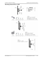
3.
Installing the Airmux-400 Units
Mounting the ODUs
³
To mount the ODU on a pole or a wall:
1. Ensure that the ODU is properly grounded.
2. Mount the ODU onto the pole or wall. Ensure that the unit is oriented so that
the cable connectors are at the bottom. (If they are on top, water may
penetrate into the unit causing damage.)
Notes
• Do not tighten the ODU to its mounting brackets until the alignment process
of the antenna is complete.
• Ensure that there are no direct obstructions in front of the ODU or
interference from man-made obstacles.
Mounting an External Antenna
³
To mount an external antenna:
1. To mount an external antenna ensure that the antenna is properly grounded
and then mount the antenna onto the pole.
2. Follow the mounting instructions supplied with the antenna.
Performing Outdoor Connections
³
To complete the outdoor connections:
1. Connect the ground cable to the ODU chassis as marked on the ODU.
2. Connect the antenna cable(s) to the ODU.
3. Connect the lightning protection device to the ODU.
4. Attach the ODU-IDU cable to the ODU RJ-45 connector.
5. Screw in the cable glands to ensure hermetic sealing of the ODU.
6. Secure the cables to the pole, mast or brackets using UV-rated cable ties.
Mounting and IDU
³
To mount an IDU:
1. If the rack already holds other equipment, ensure that it is properly
grounded.
Do not proceed with installation into a “live” rack unless it is properly grounded.
Warning
2. Attach the rack mounting brackets to the IDU.
3. Bolt the IDU into an empty slot in the rack, ensuring that it sits securely.
2
Installing the Airmux-400 Units
Airmux-400 Ver. 2.1
Installation and Operation Manual
Quick Start Guide
4. Ground the IDU to the rack using grounding lug I. The IDU should be left
permanently grounded.
Note
Instead of using the rack mounting brackets, the IDU may be rail mounted using
the four screw holes on each of its sides.
Connecting the ODU to the IDU
³
To connect the ODU to the IDU:
1. Route the cable from the ODU to the IDU, secure the cable along its path
2. Connect the cable to the ODU RJ-45 connector on the IDU.
Connecting User Equipment to the IDU
³
To connect user equipment to the IDU:
•
Connect user switch/router or any other compatible device to the IDU panel
RJ-45 ports designated LAN.
Aligning ODUs
³
To align ODUs with integrated antennas or external bipolar antennas:
1. For external bipolar antennas: Using a coax cable with N-Type connectors,
connect the vertical polarization connector of the antenna to the ANT 1
connector of the ODU.
2. For external bipolar antennas: Using a coax cable with N-Type connectors,
connect the horizontal polarization connector of the antenna to the ANT 2
connector of the ODU.
3. Ensure that power is connected to the IDUs at both sites.
4. Ensure normal operation of the IDUs by the LED indications on the front
panel.
5. Provided that site A detects the signal from site B, the ODU starts beeping 20
seconds after power up, and continues beeping until the ODUs are aligned,
and the installation is complete.
6. In the following steps, “antenna” refers both to an external antenna and an
integrated antenna.
7. Direct the antenna of site B in the direction of site A. This is simplified if a
previous site survey has been completed and azimuths are known.
Warning
When aligning the antennas, do not stand in front of a live antenna.
8. Make a horizontal sweep of 180 degrees with the site A antenna so that the
strongest signal from site B can be detected.
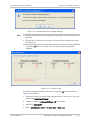
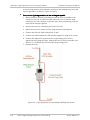
9. Slowly turn the site A antenna back towards the position of site B, listening
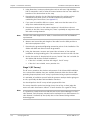
to the tone until the best signal is reached. See the following figure for
audible signal variations.
Airmux-400 Ver. 2.1
Installing the Airmux-400 Units
3
Quick Start Guide
Installation and Operation Manual
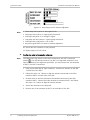
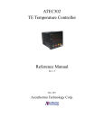
Figure 0-1. Beep Sequence for Antenna Alignment
Note
• Three beeps and a pause is 'best signal so far'.
• Two beeps and a pause is 'signal quality increased'.
• One beep and pause is 'no change in signal'.
• Long beep and short pause is 'signal quality decreased'.
• One beep and a long pause is 'no air link'.
• Any other signal does not relate to antenna alignment.
10. Secure the site A antenna to the pole/wall.
11. Repeat steps 4 to 8 for site B.
³
Note
To align two external monopolar antennas:
The ODU buzzer only works on the radio connected to the ANT 1 connector
. You will therefore need to use ANT 1 to align both antennas in turn.
marked
Upon completion of the alignment procedure, you may connect the two antennas
to ANT 1 and ANT 2 connectors.
1. Using a coax cable with N-Type connectors, connect one antenna to the ANT
1 connector of the ODU.
2. Follow the steps 3 to 7 above to align the antenna connected to the ODU
connector ANT 1 on both sides of the link.
3. On both sides of the link, disconnect the antenna connected to the ODU
connector ANT 1. Connect the other antenna to connector ANT 1 and follow
the steps 3 to 7 above to align the second antenna.
4. Secure the antennas to the pole/wall.
5. Restore one of the antennas to ANT 2 on both sides of the link.
4
Installing the Airmux-400 Units
Airmux-400 Ver. 2.1
Contents
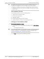
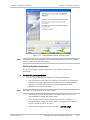
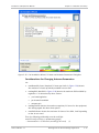
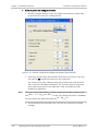
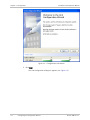
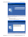
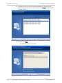
Chapter 1. Introduction 1.1 Overview.................................................................................................................... 1-1 Product Options...................................................................................................... 1-1 Applications ............................................................................................................ 1-1 Features ................................................................................................................. 1-2 Wireless Link ...................................................................................................... 1-2 LAN Interface ..................................................................................................... 1-2 Physical Configurations ...................................................................................... 1-2 Superior Spectral Efficiency ................................................................................ 1-2 Security ............................................................................................................. 1-2 Adaptive Modulation .......................................................................................... 1-3 Quality of Service ............................................................................................... 1-3 Short Time-to-Service ........................................................................................ 1-3 Management ...................................................................................................... 1-3 1.2 Physical Description ................................................................................................... 1-3 Functional Description ............................................................................................ 1-4 1.3 Technical Specifications.............................................................................................. 1-5 Chapter 2. Installation and Setup 2.1 Safety Practices ......................................................................................................... 2-1 Preventing Overexposure to RF Energy .................................................................... 2-1 Grounding .............................................................................................................. 2-2 Protection against Lightning ................................................................................... 2-2 2.2 Site Requirements and Prerequisites .......................................................................... 2-3 2.3 Package Contents ...................................................................................................... 2-3 2.4 Additional Equipment Required................................................................................... 2-4 2.5 Installation Sequence ................................................................................................. 2-5 2.6 Surveying the Site ...................................................................................................... 2-6 Planning the Link Site ............................................................................................. 2-6 Site Survey ............................................................................................................. 2-6 Stage 1 (Preliminary Survey) ............................................................................... 2-7 Stage 2 (Physical Survey) ................................................................................... 2-7 Stage 3 (RF Survey) ............................................................................................ 2-8 2.7 Outdoor Installation ................................................................................................... 2-9 Mounting the ODU .................................................................................................. 2-9 Mounting External Antennas ................................................................................... 2-9 Mounting the Lightning Protection Devices............................................................ 2-10 Outdoor Connections ............................................................................................ 2-10 2.8 Indoor Installation .................................................................................................... 2-10 Mounting the IDUs ................................................................................................ 2-10 Connecting Power to the IDU ................................................................................ 2-11 Connecting the ODU to the IDU............................................................................. 2-11 Installing a Link using PoE Devices ......................................................................... 2-12 Connecting User Equipment .................................................................................. 2-12 2.9 Connecting and Aligning ODUs / Antennas ................................................................ 2-12 2.10 Working with the Airmux Manager Application .......................................................... 2-14 Installing the Airmux Manager ............................................................................... 2-14 Starting the Airmux Manager ................................................................................. 2-14 Login Errors .......................................................................................................... 2-17 Unsupported Device ......................................................................................... 2-17 Airmux_x001e_400 Ver. 2.1
i
Table of Contents
Installation and Operation Manual
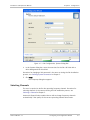
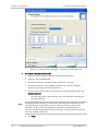
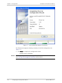
Incorrect IP Address ......................................................................................... 2-17 Incorrect Password ........................................................................................... 2-18 Continuing without an IP Address ..................................................................... 2-18 Changing the Login Password ........................................................................... 2-18 Installing the Link.................................................................................................. 2-18 Link Installation Overview ................................................................................. 2-20 Initiating the Link Installation Wizard ................................................................ 2-20 Defining System Parameters............................................................................. 2-21 Selecting a Channel .......................................................................................... 2-24 Configuring Transmit Power and Antenna Settings ............................................ 2-25 Considerations for Changing Antenna Parameters............................................. 2-27 Configuring the Services ................................................................................... 2-30 Completing the Link Installation ........................................................................ 2-31 Chapter 3. Operation 3.1 3.2 3.3 3.4 Turning On the Unit ................................................................................................... 3-1 Indicators .................................................................................................................. 3-1 Default Settings ......................................................................................................... 3-2 Configuration and Management Alternatives .............................................................. 3-3 Working with the Airmux-400 Management Utility ................................................... 3-4 Working with Telnet ................................................................................................ 3-7 3.5 Turning Off the Unit ................................................................................................... 3-9 Chapter 4. Configuration 4.1 Configuring via Configuration Wizard .......................................................................... 4-1 Configuring the System Parameters......................................................................... 4-1 Selecting Channels .................................................................................................. 4-3 Configuring the Transmit Power and Antenna Settings ............................................ 4-5 Configuring the Services.......................................................................................... 4-6 Completing the Link Configuration .......................................................................... 4-7 4.2 Configuring the Sites .................................................................................................. 4-9 4.3 Configuring for Management .................................................................................... 4-11 Configuring the System Information ...................................................................... 4-11 Defining the Management Addresses .................................................................... 4-11 Configuring VLAN Management ............................................................................. 4-12 Configuring SNMP Communities............................................................................. 4-14 Editing Community Strings ................................................................................ 4-14 Restoring Community String ............................................................................. 4-15 4.4 Configuring for Operation ........................................................................................ 4-16 Changing the Transmit Power................................................................................ 4-16 Configuring Ethernet Ports .................................................................................... 4-17 Configuring the Bridge .......................................................................................... 4-18 Selecting the ODU Bridge Mode ........................................................................ 4-18 Defining the IDU Aging Time ............................................................................. 4-19 Setting the Maximum Information Rate ................................................................. 4-19 4.5 Performing Additional Tasks ..................................................................................... 4-20 Displaying the Inventory ....................................................................................... 4-20 Changing Passwords ............................................................................................. 4-21 Changing the Management Password ............................................................... 4-21 Changing the Link Password ............................................................................. 4-22 Restoring Link Password................................................................................... 4-22 Setting the Date and Time .................................................................................... 4-22 ii
Airmux_x001e_400 Ver. 2.1
Installation and Operation Manual
Table of Contents
4.6 Muting the Beeper ................................................................................................... 4-24 Setting External Alarm Inputs ................................................................................ 4-24 Managing Configuration Files ................................................................................ 4-25 Saving the Airmux-400 Configuration in a File ................................................... 4-25 Restoring a Configuration File........................................................................... 4-25 Reinstalling the Link .............................................................................................. 4-26 Resetting Airmux-400 ........................................................................................... 4-26 Chapter 5. Monitoring and Diagnostics 5.1 Monitoring Performance ............................................................................................. 5-1 Viewing Performance Reports ................................................................................. 5-1 Saving the Monitor Log ........................................................................................... 5-4 5.2 Detecting Problems .................................................................................................... 5-5 Self-Test ................................................................................................................. 5-5 LEDs ....................................................................................................................... 5-6 Alarms and Traps .................................................................................................... 5-6 Statistic Counters ................................................................................................... 5-6 Link Compatibility Information ................................................................................. 5-6 Remote Power Fail Indication .................................................................................. 5-7 5.3 Handling Events ......................................................................................................... 5-7 Setting the Events Preferences ......................................................................... 5-10 Saving the Events Log ...................................................................................... 5-11 Resetting the Monitoring and Alarm Preferences to Defaults ............................ 5-11 5.4 Collecting Unified Performance Information .............................................................. 5-12 5.5 Troubleshooting ....................................................................................................... 5-13 5.6 Replacing an ODU .................................................................................................... 5-14 5.7 Frequently Asked Questions ..................................................................................... 5-15 5.8 Technical Support .................................................................................................... 5-16 Appendix 1. Introduction Appendix 2. Installation and Setup Appendix 3. Operation Appendix 4. Configuration Appendix 5. Monitoring and Diagnostics Appendix A. Connection Data Appendix B. Mast and Wall Installation Appendix C. Link Budget Calculator Appendix D. Lightning Protection and Grounding Guidelines Appendix E. MIB Reference Appendix F. Combo Tool Airmux_x001e_400 Ver. 2.1
iii
Table of Contents
iv
Installation and Operation Manual
Airmux_x001e_400 Ver. 2.1
Chapter 1
Introduction
1.1
Overview
Airmux-400 is a carrier-class, full duplex, 50-Mbps capacity, cost-effective multi
point-to-point broadband wireless transmission device. It transmits Ethernet
traffic over 2.3 to 2.5 GHz and 4.9 to 5.9 GHz bands, and is suitable for
deployment in FCC-regulated countries.
Product Options
Airmux-400 is available in several different frequency ranges, with versions for
ETSI and FCC regulations;
•
5.725–5.850 (FCC/IC, MII China)
•
5.825–5.875 (WPC India)
•
5.730–5.950 (universal)
•
5.470–5.725 (universal)
•
5.150–5.350 (universal)
•
4.940–4.990 (universal).
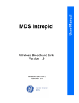
Applications
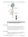
Figure 1-1 illustrates a typical point-to-point application of two Airmux-400 units.
Figure 1-1. Typical Point-to-Point Application
Airmux-400 Ver. 2.1
Overview
1-1
Chapter 1 Introduction
Installation and Operation Manual
Features
Wireless Link
Airmux-400 delivers up to 50 Mbps air rate for Ethernet traffic. The system
supports a variety of spectrum bands.
Using the following technologies, the Airmux-400 air interface is designed to
ensure nonstop, high quality transmission, even under interference and harsh
conditions
•
Automatic Adaptive Rate (AAR) is a mechanism that dynamically adapts the
air interface rate by changing both the signal modulation and coding.
•
Automatic Channel Selection (ACS) chooses the best channel by monitoring
the available radio channels and dynamically selecting a channel which is best
suited for transmission at any given time.
•
Automatic Repeat Request (ARQ) is a mechanism for error control during data
transmission. When the receiver detects an error in the received information,
it automatically requests the transmitter to resend the information. This
process is repeated until the transmission is error free or the error continues
beyond a predetermined number of maximum transmissions. Airmux-400 ARQ
mechanism is optimized for time-critical traffic.
•
Forward Error Correction (FEC) with very low overhead and algorithms
specifically designed for the varying conditions of license-exempt frequency
bands, ensuring fast, robust and error-free communications.
LAN Interface
The Airmux-400 LAN port provides 10/100BaseT interfaces with autonegotiation
and transparent VLAN support. Traffic handling is provided by a MAC-level
self-learning bridge.
Physical Configurations
Airmux multiplexers consist of an outdoor unit (ODU), an optional external
antenna and an indoor unit (IDU) with redundant DC power supplies. The outdoor
unit is suitable for mast or wall installation.
The collocation feature requires ordering the HSS unit as well as its
synchronization cables.
Superior Spectral Efficiency
Built on advanced MIMO and OFDM technologies, the Airmux-400 system provides
a high-capacity link at channel bandwidth of 20 MHz. This channel bandwidth
supports high robustness of the air interface under interference and harsh
conditions. In countries where applicable, narrow channel bandwidth reduces the
cost of the spectrum license.
Security
Data transmitted over the air interface is encrypted using Advanced Encryption
System (AES) with a 128-bit encryption key.
1-2
Overview
Airmux-400 Ver. 2.1
Installation and Operation Manual
Chapter 1 Introduction
Adaptive Modulation
Airmux-400 adaptively changes the modulation according to air conditions,
targeting maximum rate while maintaining link stability. The rate drops
temporarily after encountering interference, then automatically returns to the
highest possible rate.
Quality of Service
When the link quality is out of limits, Airmux-400 automatically searches for a
clear channel within a pre-selected list of frequencies.
Short Time-to-Service
Because Airmux-400 operates in license-exempt frequencies, it can be deployed
in record time, eliminating the costs and delays involved in leasing lines or
trenching fiber.
Management
A single SNMP-based network management application (Airmux Manager) is used
to control multiple Airmux-400 and Airmux-200 links as a unified network.
VLAN management allows the separation of user traffic from NMS traffic. The
user decides if such a separation is required. Both the headquarters and remote
sites are configured with VLAN management.
Factory settings can be restored at any time for each ODU.
Information on links and management can be collected and analyzed via a single
action.
1.2
Physical Description
An Airmux-400 system may consist of an Outdoor Unit (ODU) and an Indoor Unit
or an outdoor PoE, O-PoE, housed in a weather proof enclosure.
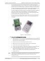
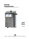
Figure 1-3 shows a typical Airmux-400 indoor unit.
Figure 1-2. Airmux-400 Indoor Unit
Airmux-400 Ver. 2.1
Physical Description
1-3
Chapter 1 Introduction
Installation and Operation Manual
Functional Description
Airmux-400 system comprises of the following units:
•
•
•
Outdoor Unit (ODU): An enclosed aluminum frame with a front sealed plastic
cover, containing an integrated transceiver with an antenna, RF module,
modem and standard interfaces. The ODU stores all the configuration
parameters of the Airmux-400 system. Figure 1-4 shows the ODU block
diagram.
Indoor Unit (IDU): The interface unit between the ODU and the user. It
converts 100–240 VAC to -48 VDC, and sends it on to the ODU. The IDU does
not store any configuration data. Therefore, there is no need for additional
configuration of the Airmux-400 system when replacing an IDU.
Outdoor PoE (O-PoE): An enclosed aluminum frame with a front sealed
aluminum cover, containing a 110–220 VAC to 48 VDC switching power supply
and an interface interconnecting an un-powered Ethernet infrastructure to
ODU.
Figure 1-3. ODU Block Diagram
1-4
Physical Description
Airmux-400 Ver. 2.1
Installation and Operation Manual
1.3
Radio
Chapter 1 Introduction
Technical Specifications
Frequency Bands
(GHz)
5.725–5.850 (FCC/IC, MII China)
5.825–5.875 (WPC India)
5.730–5.950 (universal)
5.470–5.725 (universal)
5.150–5.350 (universal)
4.940–4.990 (universal)
Data Rate
Up to 50 Mbps, full duplex, user-configurable
Channel Bandwidth
20 MHz
Duplex Technique
TDD
Modulation
2×2 MIMO-OFDM (BPSK, QPSK, 16 QAM, 64 QAM), see
Table 1-1
Transmit Power
See Table 1-1
Error Correction
FEC, k = 1/2, 2/3, 3/4, 5/6, see Table 1-1
Encryption
AES 128
Regulation
FCC 47 CFR Part 15 Subpart C
IC (Canada) RSS-210
WPC India
MII China
Antennas
LAN Interface
Airmux-400 Ver. 2.1
Table 1-2
Number of Ports
2
Type
10/100BaseT, autonegotiation
Framing/Coding
IEEE 802.3u
Bridging
Self-learning, up to 2048 MAC addresses
Traffic Handling
MAC layer bridging, self-learning
Latency
3 msec (typical)
Line Impedance
100Ω
VLAN Support
Transparent
Connector
RJ-45
Technical Specifications
1-5
Chapter 1 Introduction
Indicators
Alarm
Connector
Power
Physical
Environment
Installation and Operation Manual
PWR (green)
Power status (IDU only)
IDU (green)
IDU-E status
ODU (green/red)
ODU-to-IDU link status
AIR I/F (green/red)
Link status
SVC (green/red)
E1/T1 signal status
Connector
DB-25 female
Electrical
Characteristics
Dry contact, 30V/2A
Max input current, 0.01A at 0.5W (R=5K)
DC
-20 to -60 VDC (24 VDC or 48 VDC nominal) via AC/DC
converter
Power Consumption
35W max (ODU with IDU)
Connector
3-pin terminal block
ODU (with integrated
antenna)
Height: 371 mm (14.8 in)
Width: 371 mm (14.8 in)
Depth: 9 mm (3.6 in)
Weight 3.5 kg (7 lb)
IDU
Height: 45 mm (1.7 in)
Width: 436 mm (17.2 in)
Depth: 210 mm (8.3 in)
Weight 1.5 kg (3.3 lb)
Temperature
ODU: -35°C to +60°C (-31°F to +140°F)
IDU: 0°C to +50°C (32°F to +122°F)
Humidity
ODU: Up to 100% non-condensing, IP67
IDU: Up to 90%, non-condensing
1-6
Technical Specifications
Airmux-400 Ver. 2.1
Installation and Operation Manual
Chapter 1 Introduction
Table 1-1. Radio Link Characteristics
Modulation
BPSK
QPSK
16 QAM
64 QAM
Rate (Single
Antenna)
Rate (Dual Antenna)
FEC
Max Tx Power
[Mbps]
[Mbps]
[k = ]
[dBm]
22
N/A
13
1/2
13
26
1/2
19.5
39
3/4
26
52
1/2
29
78
3/4
52
104
2/3
58.5
117
3/4
65
130
5/6
22
22
20
Table 1-2. Antenna Options
Antenna Type
Frequency
Gain
Beam
[GHz]
[dBi]
[degrees] [mm]
Integrated Flat panel
4.9x–5.875
23
9
371×371×401.2×1.2×1.5 2.5 5.5 2 × N-type
External
5.150–5.875
28
5.6
Diam. 620
Dish
Note
Airmux-400 Ver. 2.1
Dimensions
[in]
Weight Connector
[kg] [Ib]
Diam. 24.4 20.4 45 2 × N-type
The range of the system depends on the system configuration. For further
information, contact the RAD partner nearest you or one of RAD's offices
worldwide.
Technical Specifications
1-7
Chapter 1 Introduction
1-8
Technical Specifications
Installation and Operation Manual
Airmux-400 Ver. 2.1
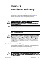
Chapter 2
Installation and Setup
This section describes the installation, alignment, and setup procedures for an
Airmux-400 system.
After installing the hardware and establishing a link, refer to Chapter 3 for
operation instructions and Chapter 4 for configuration instructions.
In case a problem is encountered, refer to Chapter 5 for test and diagnostic
instructions.
Internal settings, adjustment, maintenance, and repairs may be performed only
by a skilled technician who is aware of the hazards involved.
Warning
Note
Always observe standard safety precautions during installation, operation, and
maintenance of this product.
Before installing the product, review Handling Energized Products at the
beginning of the manual.
2.1
Warning
Safety Practices
Outdoor units and antennas should be installed ONLY by experienced installation
professionals who are familiar with local building and safety codes and, wherever
applicable, are licensed by the appropriate government regulatory authorities.
Failure to do so may expose the end user or the service provider to legal and
financial liabilities. RAD and its resellers or distributors are not liable for injury,
damage or violation of regulations associated with the installation of outdoor
units or antennas.
Preventing Overexposure to RF Energy
To protect against overexposure to RF energy, install the ODUs so as to provide
and maintain minimal separation distances from all persons.
When the system is operational, avoid standing directly in front of the antenna.
Strong RF fields are present when the transmitter is on. The ODU must not be
deployed in a location where it is possible for people to stand or walk
inadvertently in front of the antenna.
Warning
Airmux-400 Ver. 2.1
Do not activate indoors an ODU with an integrated or external antenna. To test
an active radio link inside the building, use an attenuated RF cable (at least 40 db)
for the ODU connection.
Safety Practices
2-1
Chapter 2 Installation and Setup
Installation and Operation Manual
Grounding
All RAD products should be grounded during operation. In addition:
•
The ODU should be earthed by a wire with diameter of at least 12 AWG.
The Airmux-400 ODU must be properly grounded to protect against lightning.
It is the user's responsibility to install the equipment in accordance with
Section 810 of the National Electric Code, ANSI/NFPA No.70-1984 or
Section 54 of the Canadian Electrical Code. These codes describe correct
installation procedures for grounding the outdoor unit, mast, lead-in wire and
discharge unit. It also lays down the size of grounding conductors and
connection requirements for grounding electrodes.
The Airmux-400 ODU must be grounded to a protective earth as described in
Appendix D and in accordance with the local electrical regulations.
•
The earth lug on the IDUE should be connected to the protective earth at all
times, by a wire with a diameter of 18 AWG or wider. Rack-mounted
equipment should be mounted only in earthed racks and cabinets.
•
Always make the ground connection first and disconnect it last
•
Never connect telecommunication cables to ungrounded equipment
•
Ensure that all other cables are disconnected before disconnecting the
ground.
More detailed grounding guidelines are supplied in Appendix D.
Protection against Lightning
The use of lightning protection is dependent on regulatory and end user
requirements. All of RAD outdoor units are designed with surge limiting circuits to
minimize the risk of damage due to lightning strikes. RAD recommends the use of
additional surge arrestor devices to protect the equipment from nearby lightning
strikes.
See Appendix D for detailed installation instructions of lightning protection
devices.
2-2
•
It is recommended that installation of the outdoor unit be contracted to a
professional installer.
•
Before working on equipment connected to power lines or telecommunication
lines, you should remove jewelry or any other metallic object that may come
into contact with energized parts.
•
Use extreme care when installing antennas near power lines.
•
Use extreme care when working at heights.
•
When using an AC power source for Airmux-400 always use the AC power
adapter supplied by RAD.
•
Use the right tools. In addition to standard tools required for any kind of ODU
or antenna installation, Airmux-400 requires additional specific tools detailed
in the Additional Equipment Required section below.
Safety Practices
Airmux-400 Ver. 2.1
Installation and Operation Manual
2.2
Chapter 2 Installation and Setup
Site Requirements and Prerequisites
For the IDU units, allow at least 90 cm (36 in) of frontal clearance for operating
and maintenance. Allow at least 10 cm (4 in) clearance at the rear of the unit for
signal lines and interface cables.
The ambient operating temperature should be –35° to 60°C (–31° to 140°F)
(ODU), or 0° to 50°C (32° to 122°F) (IDU) at a relative humidity of up to 100%
(ODU) or 90% (IDU), non-condensing.
2.3
Package Contents
The Airmux-400 packages include the following items:
•
ODU package containing:
One ODU, see Figure 2-1, Figure 2-2
An ODU mounting kit
Label showing the MAC address and the alternative community string. The
label is self-adhesive. You should keep this label safe.
Cable glands (to be used with the ODU-IDU cable).
Figure 2-1. Connectorized ODU, Front and Rear Views
Airmux-400 Ver. 2.1
Package Contents
2-3
Chapter 2 Installation and Setup
Installation and Operation Manual
Figure 2-2. Integrated ODU, Front and Rear Views
•
IDU package containing:
IDUE
19-inch rack mounting kit
Two DC power plugs for power cables.
Or
•
External antenna (if ordered)
Antenna
RF cable 1m (3 ft) long; two cables supplied with bipolar antennas, single
cable supplied with monopolar antennas
Mounting kit.
2.4
Additional Equipment Required
The following is a list of the equipment and materials required to install
Airmux-400 hardware.
•
•
2-4
Tools and materials:
Crimping tool for RJ-45 (if the ODU-IDU cable is without connectors)
Spanner/wrench 13 mm (0.5 in)
Drill (for wall mounting only)
Cable ties
Sealing material
Cables and connectors:
ODU grounding cable 12 AWG
IDU grounding cable 18 AWG
ODU-IDU cable (outdoor class, CAT-5e, 4 twisted pairs, 24 AWG).
Additional Equipment Required
Airmux-400 Ver. 2.1
Installation and Operation Manual
2.5
Chapter 2 Installation and Setup
Installation Sequence
Install the Airmux-400 system according to the following the steps:
1. Survey the site
2. Mount the ODUs, see Appendix B
3. Mount the external antennas (if used), see Appendix B
4. Mount the lightning protection devices (if used), see Appendix D
5. Perform outdoor connections, see Outdoor Connections
6. Mount the IDUs, see Mounting the IDUs.
7. Perform indoor connections, Connecting the ODU to the IDU.
8. Align the ODUs/antennas, page Connecting and Aligning ODUs / Antennas.
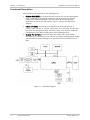
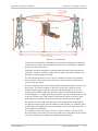
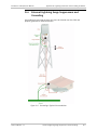
Figure 2-3 illustrates a typical installation of Airmux-400 with an external
antenna.
Figure 2-3. Typical Installation Diagram (with External Antenna)
Airmux-400 Ver. 2.1
Installation Sequence
2-5
Chapter 2 Installation and Setup
2.6
Installation and Operation Manual
Surveying the Site
This section explains how to survey the site intended for Airmux-400 installation.
Planning the Link Site
Link site planning consists of a set of surveys, which must be carried out before
any equipment is brought to the site. If for some reason, the outcome of any of
these surveys is negative, site re-location will need to be considered.
A site survey consists of three stages:
•
Preliminary survey – The proposed link is analyzed in the office using a
topographic map.
•
Physical survey – The locations of the Airmux-400 indoor and outdoor
equipment are determined on-site.
•
Radio Frequency (RF) survey – It is recommended that the installation area be
scanned with a spectrum analyzer, to identify RF interference so as to
determine a clear channel for Airmux-400 installation (on-site).
Site Survey
Airmux-400 wireless links must be planned before installation. The designated
installation site must be appraised to determine that the wireless system is able
to operate efficiently and provide connectivity without signal degradation.
Airmux-400 offers a wide operating frequency range. A free frequency channel
must be determined within the operating range, for optimum performance.
Recommended equipment:
•
•
2-6
Stage 1 (preliminary survey)
Topological map of the area
Urban map of the area
Compass
Stage 2 (physical survey)
100 meter tape measure
Ohmmeter, to check ground connection
Binoculars
Map
Digital camera
Paper, pencil, and a clipboard
GPS device (optional)
Compass (optional)
Surveying the Site
Airmux-400 Ver. 2.1
Installation and Operation Manual
•
Chapter 2 Installation and Setup
Stage 3 (RF survey)
Spectrum analyzer with Max Hold function and screen capture facility that
can store multiple images, for documentation purposes
RF accessories (connectors and cables)
Communication devices (for example, cellular phones, or a set of walkie
talkies).
Stage 1 (Preliminary Survey)
A preliminary survey is necessary before visiting potential installation sites. As
much detail as possible should be obtained about the two designated ODU
installation sites and the area between them.
³
To perform a preliminary survey:
1. Mark the two designated installation sites on a topographic map of the area.
2. Measure the distance between the sites; check that it is within the specified
range of Airmux-400.
3. On the urban map, check for developed areas situated between the two
installation sites. Pay attention to these areas when performing the physical
site survey; there may be tall buildings, RF towers, or transmitters, which
could cause interference to the link.
4. Check the area between the two sites for obstructions such as:
High ground - hills or mountains
Lakes or large bodies of water. Water has a reflection effect on RF signals
like a building. This type of reflection causes the received amplitude to be
reduced. As a rule of thumb, the presence of a large body of water
between the link sites may double the required antenna height.
5. Determine and record the compass bearings between both ODUs, relative to
north.
6. If there are obstructions between the two sites, calculate the Fresnel Zone
(see Appendix C for details).
7. If the site chosen does not meet requirements, consider alternative sites.
8. Use the Link Budget Calculator (on the CD supplied with Airmux-400 or using
the Airmux Manager) to determine the expected performance.
Stage 2 (Physical Survey)
The physical site survey reviews the environment of the proposed Airmux-400
installation location, to ensure that the link sites are suitable for the wireless
network. The results of the physical site survey should be recorded.
Note
³
It is advisable to go on a clear day, so you can more easily see any obstructions
between the two sites.
To perform a physical survey:
1. From the compass readings taken in the preliminary survey, find the azimuth
(horizontal position) that the ODU should face towards the second ODU.
Airmux-400 Ver. 2.1
Surveying the Site
2-7
Chapter 2 Installation and Setup
Installation and Operation Manual
2. Using binoculars, locate any obstructions such as tall trees, high buildings,
hills or mountains. Look for other RF towers between the two sites. Mark the
locations of the obstructions on the map.
3. Determine the location for the ODU (having regard for existing rooftop
installations and tower space). It should be above any obstructions,
considering the Fresnel zone (see Appendix C).
4. If you need to install the ODU on a tower, make sure that the tower is far
away from overhead electric power lines.
5. Determine a location for the indoor equipment; it should be as close as
possible to the ODU. At an existing site, there is probably an equipment room
with cable-routing channels.
Note
The IDU–ODU cable length limit is 100m, in accordance with IEEE 10/100BaseT
requirements.
6. Measure and record the path length of the cable from the ODU position to
the indoor equipment room.
7. Determine the ground and lightning connection points of the installation. The
AirMux-400 ODU and IDU must both be grounded.
8. Using the ohmmeter, measure and record the resistance of the required
installation to the grounding point. The resistance must be less than 1O ohm.
9. Review the results of the physical site survey. Decide if the site is suitable for
the AirMux-400 wireless network installation.
If the site is suitable, continue with stage 3, the RF survey
If the site is not suitable, survey another site.
Stage 3 (RF Survey)
The RF survey examines the wireless environment of the Airmux-400 installation
site, to determine whether there are available channels within the Airmux-400
operating frequency band. An RF survey is performed using a spectrum analyzer.
It is advisable to familiarize yourself with the spectrum analyzer before going out
on site, specifically the Max Hold and Marker functions.
You should perform the RF survey at both proposed link sites.
The survey should be carried out during a busy time of day, to best judge the
worst-case radio interference. Allow 2–4 hours duration for a good RF survey.
Note
2-8
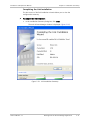
It is possible to install the Airmux-400 link and use the Airmux Manager to find a
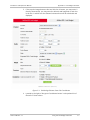
clear channel. Each frequency channel can be evaluated in turn. Achievement of a
clear channel is indicated by the Quality bar on the Channel Setting window
becoming green.
Surveying the Site
Airmux-400 Ver. 2.1
Installation and Operation Manual
2.7
Chapter 2 Installation and Setup
Outdoor Installation
Mounting the ODU
The ODU can be mounted on a pole or a wall. In both installations, the supplied
mounting kit is used to secure the ODU.
Note
A mast-sited ODU typically uses a pole attached to the mast.
An Airmux-400 link operates in pairs of two ODUs with the same configuration.
Both ODUs must be installed, and the antennas aligned for maximum throughput.
Warning
Prior to connecting cables to the ODU, the protective earth terminal (screw) of
the ODU must be connected to an external protective ground conductor or to a
grounded pole.
• Only a qualified person using the proper safety equipment should climb the
antenna mast
• Only qualified professional personnel should install or dismantle ODUs and
masts.
³
To mount the ODU on a pole or a wall:
1. Ensure that the ODU is properly grounded.
2. Mount the ODU onto the pole or wall. Ensure that the unit is oriented so that
the cable connectors are at the bottom. (If they are on top, water may
penetrate into the unit causing damage.)
3.
Notes
Refer to Appendix B for detailed ODU mounting kit contents and schematics.
• Do not tighten the ODU to its mounting brackets until the alignment process
of the antenna is complete.
• Ensure that there are no direct obstructions in front of the ODU or
interference from man-made obstacles.
Mounting External Antennas
If you are using ODU with an integrated antenna, skip to Mounting the Lightning
Protection Devices below.
The supplied mounting kit is used to mount the antenna onto a pole. The
antennas must be aligned for maximum throughput.
Warning
³
Do not stand in front of a live antenna.
To mount an external antenna:
1. To mount an external antenna ensure that the antenna is properly grounded
and then mount the antenna onto the pole. Refer to Appendix B for detailed
antenna mounting instructions.
2. Follow the mounting instructions supplied with the antenna.
Airmux-400 Ver. 2.1
Outdoor Installation
2-9
Chapter 2 Installation and Setup
Installation and Operation Manual
Mounting the Lightning Protection Devices
The use of lightning protection is dependent on regulatory and end user
requirements. The Airmux-400 ODU is designed with surge limiting circuits to
minimize the risk of damage due to lightning strikes. RAD recommends the use of
additional surge arrestor devices to protect the equipment from nearby lightning
strikes.
Refer to Appendix D for detailed installation instructions of lightning protection
devices.
Outdoor Connections
Connect the outdoor devices once they are installed.
³
To complete the outdoor connections:
1. Connect the ground cable to the ODU chassis as marked on the ODU.
3. Connect the antenna cable(s) to the ODU.
4. Connect the lightning protection device to the ODU (see Appendix D).
5. Attach the ODU-IDU cable to the ODU RJ-45 connector (see Appendix A)for
the connector pinout)
6. Screw in the cable glands to ensure hermetic sealing of the ODU.
7. Secure the cables to the pole, mast or brackets using UV-rated cable ties.
2.8
Indoor Installation
Mounting the IDUs
The Airmux-400 IDUs are all rack mounted. A front panel keyed schematic of a
rack mounted IDUE is shown in Figure 2-4.
Figure 2-4. IDUE Front Panel
2-10
Indoor Installation
Airmux-400 Ver. 2.1
Installation and Operation Manual
³
Chapter 2 Installation and Setup
To mount an IDU:
1. If the rack already holds other equipment, ensure that it is properly
grounded.
Do not proceed with installation into a “live” rack unless it is properly grounded.
Warning
2. Attach the rack mounting brackets (K) to the IDU.
3. Bolt the IDU into an empty slot in the rack, ensuring that it sits securely.
4. Ground the IDU to the rack using grounding lug I. The IDU should be left
permanently grounded.
Note
Instead of using the rack mounting brackets, the IDU may be rail mounted using
the four screw holes on each of its sides.
Connecting Power to the IDU
The IDUE has redundant power connection circuits.
The connectors are 3 pin in line female, with polarities (left to right) minus,
ground, plus. To avoid damage to the IDU, always use an AC/DC adapter supplied
by RAD.
Ensure that the IDUs at both sites are powered up.
Figure 2-5. IDUE Power Connectors
Connecting the ODU to the IDU
The ODU-IDU cable conducts all the user traffic between the IDU and the ODU,
and also provides power to the ODU. The maximum length of the ODU-IDU cable
is 100m (328 ft) in accordance with 10/100BaseT standards.
The ODU-IDU cable is supplied pre-assembled with RJ-45 connectors, at the
length specified when ordering, or as a cable drum with spare connectors. If the
ODU-IDU cable was not ordered, use an outdoor class, CAT-5e 24 AWG shielded
cable. See Appendix A for wiring specifications.
³
To connect the ODU to the IDU:
1. Route the cable from the ODU to the IDU, secure the cable along its path
2. Connect the cable to the ODU RJ-45 connector on the IDU.
Airmux-400 Ver. 2.1
Indoor Installation
2-11
Chapter 2 Installation and Setup
Installation and Operation Manual
Installing a Link using PoE Devices
The PoE device is a simple unit having a power input connector and two Ethernet
ports. It is AC powered, and has a power LED.
³
To prepare a link using PoE devices:
1. To connect the ODU to the PoE device, route the cable from the ODU to the
PoE device, secure the cable along its path and connect the cable to the
P-LAN-OUT RJ-45 connector on the PoE device.
2. Connect it to AC power.
3. Repeat steps 1 to 2 for the second link.
Connecting User Equipment
³
To connect user equipment to the IDU:
•
Note
³
Connect user switch/router or any other compatible device to the IDU panel
RJ-45 ports designated LAN. Refer to Appendix A, for connector pinouts.
Do not connect two LAN ports to the same network, or flooding may occur.
To connect user equipment to the PoE device:
•
Connect a user switch, router or any other compatible device to the PoE
device RJ-45 port designated LAN-IN. Refer to Appendix A for connector
pinouts.
2.9
Connecting and Aligning ODUs / Antennas
You perform antenna alignment using the ODU's audible tone. To speed up the
installation time, alignment of an Airmux-400 system should be performed by two
teams simultaneously, at site A and at site B.
³
To align ODUs with integrated antennas or external bipolar antennas:
1. For external bipolar antennas: Using a coax cable with N-Type connectors,
connect the vertical polarization connector of the antenna to the ANT 1
connector of the ODU.
2. For external bipolar antennas: Using a coax cable with N-Type connectors,
connect the horizontal polarization connector of the antenna to the ANT 2
connector of the ODU.
3. Ensure that power is connected to the IDUs at both sites.
4. Ensure normal operation of the IDUs by the LED indications on the front
panel.
5. Provided that site A detects the signal from site B, the ODU starts beeping 20
seconds after power up, and continues beeping until the ODUs are aligned,
and the installation is complete.
2-12
Connecting and Aligning ODUs / Antennas
Airmux-400 Ver. 2.1
Installation and Operation Manual
Chapter 2 Installation and Setup
6. In the following steps, “antenna” refers both to an external antenna and an
integrated antenna.
7. Direct the antenna of site B in the direction of site A. This is simplified if a
previous site survey has been completed and azimuths are known.
Warning
When aligning the antennas, do not stand in front of a live antenna.
8. Make a horizontal sweep of 180 degrees with the site A antenna so that the
strongest signal from site B can be detected.
9. Slowly turn the site A antenna back towards the position of site B, listening
to the tone until the best signal is reached. See the following figure for
audible signal variations.
Figure 2-6. Beep Sequence for Antenna Alignment
Note
• Three beeps and a pause is 'best signal so far'.
• Two beeps and a pause is 'signal quality increased'.
• One beep and pause is 'no change in signal'.
• Long beep and short pause is 'signal quality decreased'.
• One beep and a long pause is 'no air link'.
• Any other signal does not relate to antenna alignment.
10. Secure the site A antenna to the pole/wall.
11. Repeat steps 4 to 8 for site B.
³
Note
To align two external monopolar antennas:
The ODU buzzer only works on the radio connected to the ANT 1 connector
. You will therefore need to use ANT 1 to align both antennas in turn.
marked
Upon completion of the alignment procedure, you may connect the two antennas
to ANT 1 and ANT 2 connectors.
1. Using a coax cable with N-Type connectors, connect one antenna to the ANT
1 connector of the ODU.
2. Follow the steps 3 to 7 above to align the antenna connected to the ODU
connector ANT 1 on both sides of the link.
3. On both sides of the link, disconnect the antenna connected to the ODU
connector ANT 1. Connect the other antenna to connector ANT 1 and follow
the steps 3 to 7 above to align the second antenna.
Airmux-400 Ver. 2.1
Connecting and Aligning ODUs / Antennas
2-13
Chapter 2 Installation and Setup
Installation and Operation Manual
4. Secure the antennas to the pole/wall.
5. Restore one of the antennas to ANT 2 on both sides of the link.
2.10 Working with the Airmux Manager Application
The Airmux Manager application is distributed on a CD. Operating system specific
PC resources required by the application are set out in Table 2-1.
Table 2-1. PC Requirements for the Airmux Manager Application
Windows 2000
Windows XP Pro
Windows Vista
Memory
128 MB
512 MB
1 GB
Processor
P III
P IV
P IV Dual Core
Requirements common to all systems are:
•
Hard disk: 1 GB free space
•
Network: 10/100BaseT NIC
•
Graphics: 1024 × 768 screen resolution with 16 bit color
•
Microsoft Explorer version 5.01 or later.
Installing the Airmux Manager
³
To install the Airmux Manager:
1. Insert the CD-ROM into your CD-ROM drive.
The installation starts automatically.
2. Follow the on-screen instructions of the installation wizard to complete setup
of the Airmux Manager program in the desired location.
Starting the Airmux Manager
³
To start the Airmux Manager:
1. Connect the managing computer to one of the two LAN ports of the IDUE as
shown below.
2-14
Working with the Airmux Manager Application
Airmux-400 Ver. 2.1
Installation and Operation Manual
Chapter 2 Installation and Setup
Figure 2-7. LAN Ports on the Front Panel of the IDUE
If you are not using a direct connection as above, ensure that you have IDU to
managing computer connectivity (e.g. through a LAN).
2. Check that you have connectivity to the ODU. You can do this by opening up
a command line session (Start>Run and then type, cmd). At the command
prompt, type: ping 10.0.0.120
You should receive a reply from Airmux-400.
Figure 2-8. Pinging an Uninstalled and Unconfigured Link
Any other response from ping means that the ODU is not responding. Check your
Ethernet connection and that both the IDU and ODU are switched on and then try
again.
3. Dismiss the command line session.
4. Double-click the Airmux Manager icon on the desktop, or click Start >
Programs > Airmux Manager > Airmux Manager.
The Login dialog box appears.
Airmux-400 Ver. 2.1
Working with the Airmux Manager Application
2-15
Chapter 2 Installation and Setup
Installation and Operation Manual
Figure 2-9. Login Screen
5. Type an IP address for the ODU (if you connect through a network), or click
Local Connection (if you are connected directly to the IDU port).
Caution • If you log in on Local Connection, but your physical connection is not local (i.e.
anything other than a direct connection between the managing computer and
the IDU), then any configuration you carry out may affect other links in the
network.
• If you log in via an over-the-air IP address, you will receive a warning. If you
reset the site to which you are connected to factory settings, you can lock
yourself out of the link.
• Network login (IP address to the ODU) is recommended.
Note
The default IP address for the ODU is 10.0.0.120. The subnet mask is 255.0.0.0.
The actual IP address is defined during link configuration (see Chapter 4).
6. Enter the password. The default password is admin.
7. If you are a user with Read-Write permission, click Options to enter the
Community options.
Note
2-16
If you are using the system for the first time, leave the default
Community passwords, netman for read-write, and public for read-only.
If Community values were previously defined, enter them under
Community in the Read-Only or Read-Write boxes.
If you are a user with read-only permission, click the Read Only Mode
check box.
Airmux-400 is protected with Community passwords. A user may be defined with
read-only permission or with read-write permission (see Chapter 4 for more
details).
Working with the Airmux Manager Application
Airmux-400 Ver. 2.1
Installation and Operation Manual
Chapter 2 Installation and Setup
Figure 2-10. Login Screen with Community Options Visible
Login Errors
This section describes problems that may occur during login.
Unsupported Device
Attempting to connect to an unsupported device results in the following error
message:
Figure 2-11. Unsupported Device Message
Incorrect IP Address
If the IP address chosen is invalid or the link is unreachable, the following error
message will be displayed:
Airmux-400 Ver. 2.1
Working with the Airmux Manager Application
2-17
Chapter 2 Installation and Setup
Installation and Operation Manual
Figure 2-12. Unreachable Device Message
In both of the above situations, you will see a warning graphic
IP Address field.
alongside the
Incorrect Password
If you type an incorrect password in the Login screen, a warning graphic
displayed alongside the password field.
is
Continuing without an IP Address
The Airmux Manager provides limited “offline” functionality when there is no
accessible IDU/ODU. It is primarily for setting managing computer related
parameters and running the Link Budget Calculator.
Changing the Login Password
³
To change the login password:
1. From the Tools menu, select Change Password.
The Change Password dialog box appears.
2. Enter the current password, and the new password.
3. Click OK to confirm.
Installing the Link
After the login the main Airmux Manager window is displayed.
If the login is successful, Airmux-400 displays the opening window.
2-18
Working with the Airmux Manager Application
Airmux-400 Ver. 2.1
Installation and Operation Manual
Chapter 2 Installation and Setup
Figure 2-13. Airmux Manager Main Window
The procedure required to make the link functional has three phases:
1. Link Installation – detailed below.
Installation actually gets the link operational by setting the link parameters. It
uses a fixed channel at the lowest possible modulation, BPSK at 6.5Mbps and
works under the harsh interference condition.
Note
During the installation procedure, the definition of all parameters is automatically
applied to both sides of the link.
2. Link Configuration (see Chapter 4)
Configuration provides much the same functionality as Installation, but for a
running link. A fallback to Installation mode is provided for situations which
cannot be handled without resetting the link, such as antenna realignment
and IDU or ODU replacement.
The Link Installation and Configuration phases are both carried out with
Wizards, which “walk you through” the processes. The Wizards are visually
quite similar and will be described in detail below.
3.
Site Configuration (see Chapter 4)
Site specific configuration for each side of the link is available at any time under a running link or under the restricted Installation mode.
Site Configuration consists of a set of panels, which may be invoked
individually in any order, as needed.
Airmux-400 Ver. 2.1
Working with the Airmux Manager Application
2-19
Chapter 2 Installation and Setup
Note
Installation and Operation Manual
An installed and configured link can be returned to installation mode for reinstallation and configuration from last settings or from factory settings.
• Reversion to installation mode requires a complete break in the link service
• Configuration mode may vary the service throughput and quality, but without
a service break.
Link Installation Overview
Link installation procedure includes the following steps:
1. Initiating the link installation wizard
2. Defining system parameters
3. Selecting a channel
4. Defining transmit power and system settings
5. Viewing configuration summary and completing the wizard.
Initiating the Link Installation Wizard
³
To initiate the link installation wizard:
1. In the tool bar of the Airmux Manager main window, click the Link Installation
button.
The Installation Wizard opens.
Note
The Link Installation button is only accessible if antennas are properly aligned. If
this box is “grayed out”, you should align the antennas as described in the
Connecting and Aligning ODUs / Antennas section above.
2. Click Next to proceed with the installation procedure.
2-20
Working with the Airmux Manager Application
Airmux-400 Ver. 2.1
Installation and Operation Manual
Chapter 2 Installation and Setup
Figure 2-14. Link Installation Wizard, Opening Screen
Note
The bottom data area reproduces the corresponding data from the main window,
which is obscured by the above panel.
Defining System Parameters
The System dialog box allows configuration of the general link and site
parameters.
³
To define the system parameters:
1. From the System dialog box, configure the following parameters:
Note
Airmux-400 Ver. 2.1
Link ID, which must be unique for each link in the area. The Link ID must
include at least eight alphanumeric characters. Up to 24 characters are
allowed. For maximum security, use a Link ID composed of both
alphabetic and numeric characters.
Both sides of a link must have the same Link ID.
Link Name for the link identification. The default name is “Link”. It is
recommended to change the default name.
Site 1 and Site 2 names. The default names are both “Location”. It is
recommended to change the default names. Throughout this manual, A
for Site 1 and B for Site 2 are used.
Link password (optional). Default password is wireless-bridge.
Working with the Airmux Manager Application
2-21
Chapter 2 Installation and Setup
Note
Installation and Operation Manual
The link password is associated with the link, it does not have anything to do
with the Airmux Manager login password.
If an incorrect password is entered, a link is established but configuration cannot
be performed and no services are available. A new link password may be obtained
from RAD. You can also acquire an alternative password as explained below.
2. Click Next to continue.
Airmux-400 starts evaluating the link at a default rate of 6.5 Mbps.
Figure 2-15. Link Installation Wizard, System Dialog Box
³
To change the link password:
1. Click the Change button in the System dialog box.
The Change Link Password dialog box opens.
2. Enter the current link password. (The default link password for a new ODU is
wireless-bridge). Select the Hide characters check box for maximum security.
3. Enter a new password.
4. Confirm the new password.
2-22
Working with the Airmux Manager Application
Airmux-400 Ver. 2.1
Installation and Operation Manual
Chapter 2 Installation and Setup
Figure 2-16. Change Link Password Dialog Box
³
To acquire a new password:
1. Click the Forgotten Link Password button.
Link Password Recovery dialog box is displayed.
Figure 2-17. Link Password Recovery dialog box
2. Follow the instructions to use the Alternative Link Password, and click OK to
finish.
The Change Link Password dialog box is displayed.
3. Enter a new password.
4. Retype the new password in the Confirm field.
5. Confirm the link password change.
6. Click OK to complete the procedure.
Airmux-400 Ver. 2.1
Working with the Airmux Manager Application
2-23
Chapter 2 Installation and Setup
Note
Installation and Operation Manual
• Restoring Factory Defaults returns the Link Password to wireless-bridge.
• If the link is inactive, then the link password may also be changed from the
Site Configuration dialogs.
Selecting a Channel
Airmux-400 features an Automatic Channel Selection (ACS). In the event of sync
loss, ACS chooses the first available channel in a list of monitored channels. A
channel switch takes place sufficiently fast as to ensure no loss of service.
Default frequency is 5.780 GHz.
Figure 2-18. Link Installation Wizard, Channel Settings Dialog Box
³
To select channels to be used by the link:
1. Select the main frequency from the Installation Channel box.
Note
Currently the channel bandwidth is permanently set to 20 MHz
2. Click the check box if Automatic Channel Selection is required.
2-24
Working with the Airmux Manager Application
Airmux-400 Ver. 2.1
Installation and Operation Manual
Chapter 2 Installation and Setup
3. The Available Channels List contains all of the allowable channels for the link.
Check the channels that can be automatically selected.
Selecting a new channel causes the system quality to change. The Quality
bar provides an indication of the link quality from poor (red) to good
(green).
4. Click Next.
Configuring Transmit Power and Antenna Settings
The choice of Tx power, antenna gain and cable loss determines the EIRP and is
affected by such considerations as radio limitations and regulatory restrictions.
Before proceeding to antenna installation details, the following background
information should be considered:
Each Airmux-400 ODU is made of two radio transceivers (radios). The radios
make use of algorithms that utilize both polarization and space diversity resulting
in enhanced capacity, range and link availability. The number of antennas (i.e.
radios) used is determined by user configuration and by automatic system
decisions, explained below.
Dual Antennas at Both Sites
Using dual antennas at both sites (single bipolar antenna or two monopolar
antennas) enables the use of MIMO technology. With MIMO the system doubles
the link capacity. At the same time, it keeps the same rate and modulation per
radio as was used with single antenna, thus increasing capacity, range and
availability.
For example, with a dual antenna Airmux-400 transmits at modulation of 64 QAM
and FEC of 0.83 and get an air rate of 130 Mbps, compared to 65 Mbps with
single antenna.
To work in this mode, each antenna port must be connected to an antenna, the
RSS level in both receivers should be balanced and a minimal separation between
the antennas must be maintained. (For example, by using dual polarization
antennas a cross polarization separation is attained).
Upon selecting Antenna Type as Dual, Airmux-400 automatically doubles the air
rates.
Airmux Manager indicates a case of unbalanced RSS between the two antennas.
Single Antennas at Both Sites
By selecting a single antenna at both sites the ODUs operate with a single radio
that is connected to the ANT 1 connector. The second radio is automatically shut
down.
Single and Dual Antennas
In this mode one of the sites uses the ODU with a single antenna while the other
site uses the ODU with a dual antenna.
The advantages in this mode in comparison to using a single antenna in both
sites are doubled total Tx power and additional polarization and/or space
diversity.
Airmux-400 Ver. 2.1
Working with the Airmux Manager Application
2-25
Chapter 2 Installation and Setup
Installation and Operation Manual
Airmux-400 automatically switches to this mode if one of the ODUs is connected
to a dual antenna or if the RSS at one of the ODU receivers is below minimal
level.
The air rates used in this mode are same as when using single antennas in both
sites.
The rates used by Airmux-400 are shown below:
Table 2-2. Transmission Rates
2-26
Radio
Modulation
FEC
Air-Rate
[Mbps]
Single
BPSK
1/2
6.5
Single
QPSK
1/2
13
Single
QPSK
3/4
19.5
Single
16QAM
1/2
26
Single
16QAM
3/4
39
Single
64QAM
2/3
52
Single
64QAM
3/4
58.5
Single
64QAM
5/6
65
Dual
BPSK
1/2
13
Dual
QPSK
1/2
26
Dual
QPSK
3/4
39
Dual
16QAM
1/2
52
Dual
16QAM
3/4
78
Dual
64QAM
2/3
104
Dual
64QAM
3/4
117
Dual
64QAM
5/6
130
Working with the Airmux Manager Application
Airmux-400 Ver. 2.1
Installation and Operation Manual
Chapter 2 Installation and Setup
.
Figure 2-19. Link Installation Wizard, Tx Power and Antenna Parameters Dialog Box
Considerations for Changing Antenna Parameters
Let:
•
maxAllowedTx Power (Required Tx Power per Radio in Figure 2-20) denote
the maximum Tx Power practically available from an ODU.
•
maxRegEIRP (Max EIRP in Figure 2-20) denote the maximum EIRP available by
regulation. It is determined by three factors:
per band/regulation
per channel bandwidth
antenna gain
•
maxRegTxPower denote the maximum regulatory Tx Power for the equipment,
also having regard the above three points.
•
maxODUTxPower denote the maximum Tx Power of the ODU, itself depending
on the air rate used.
Then, the following relationship must be satisfied:
maxAllowedTxPower ≤ min(maxRegEIRP
– AntennaGain + CableLoss, maxRegTxPower)
Airmux-400 Ver. 2.1
(*)
Working with the Airmux Manager Application
2-27
Chapter 2 Installation and Setup
³
Installation and Operation Manual
To set Tx power and configure antennas:
1. Click the Configure buttons in turn to configure the antennas on both sides
of the link. Each one offers a dialog like this:
Figure 2-20. Antenna Configuration Dialog with Opened Type Selection
2. Choose the antenna type and required transmission (Tx) power for the first
site and click OK. Repeat the process for the second site.
The Tx power (per radio) indicates the power of each radio inside the ODU
and is used for Link Budget Calculations. The Tx power (System) shows the
total transmission power of the ODU and is used to calculate the EIRP
according to regulations.
Note
To see the relationship between Tx Power (radio) and TX Power (system), note
that
dBm = 10 × log 10m illiWatt
so that if you double the power in milliWatts
(for two radios) then dBm will increase by
10 × log 102 ≈ 3
.
3. Set the Antenna Gain and Cable Loss. If do this you will receive a warning
message:
2-28
Working with the Airmux Manager Application
Airmux-400 Ver. 2.1
Installation and Operation Manual
Chapter 2 Installation and Setup
Figure 2-21. Antenna Parameters Change Warning
Note
• The Max EIRP level will be automatically set according to the selected band and
regulation.
• The EIRP level is the sum of the System Tx power and the Antenna Gain minus
the Cable Loss.
If inequality (*) above is violated, then the following warning window is
displayed:
Figure 2-22. Tx Power Limits
The precise relationship between the items in inequality (*) and the window of
Figure 2-20 is follows:
Airmux-400 Ver. 2.1
•
Required Tx Power (per radio) will be adjusted down to the lesser of the value
entered and maxAllowedTxPower
•
TxPower (system)is maxAllowedTxPower + 3 (for 2 radios)
•
Max EIRP is maxRegEIRP.
•
EIRP is maxAllowedTx Power + Antenna Gain - Cable Loss
Working with the Airmux Manager Application
2-29
Chapter 2 Installation and Setup
Installation and Operation Manual
The table in Figure 2-22 only shows rates where the maximum Tx Power is the
limitation, rather than regulations.
Note
The maxAllowedPower and maxEIRP are regulatory. In an unregulated
environment, the only limit is maxODUTxPower.
When you close the window of Figure 2-22, the change you requested will
not be honored, and you will need to try again.
4. When you are finished with Tx Power configuration, click Next.
Configuring the Services
Currently Ethernet Only is the only available service. You may choose a specific
modulation rate or use Adaptive.
³
To configure the services:
1. In the Services dialog box, choose Adaptive or one of the available rates
2. Click Next to continue.
Figure 2-23. Link Installation Wizard, Services Dialog Box
2-30
Working with the Airmux Manager Application
Airmux-400 Ver. 2.1
Installation and Operation Manual
Chapter 2 Installation and Setup
Completing the Link Installation
The last screen of the link installation wizards allows you to view the
configuration summary.
³
To complete the link installation:
•
In the Installation Summary dialog box, click Done.
The main Airmux Manager window is displayed (Figure 2-25).
Figure 2-24. Link Installation Summary
Airmux-400 Ver. 2.1
Working with the Airmux Manager Application
2-31
Chapter 2 Installation and Setup
Installation and Operation Manual
Figure 2-25. Main Window after Link Installation
³
To verify the installation:
•
Verify that the Radio Signal Strength (RSS) is according to expected results as
determined by the Link Budget Calculator.
Caution Installation mode, as described above, may be re-entered using Configuration | 1
Configure Site A and Installation Mode the Site Configuration dialog. Some
Installation mode functionality may cause a break in link service.
If you can accomplish link changes without breaking the service, always prefer to
use Link Configuration mode, described in Chapter 4.
2-32
Working with the Airmux Manager Application
Airmux-400 Ver. 2.1
Chapter 3
Operation
This section provides the following information for Airmux-400:
•
Operating procedures (turning-on and turning-off)
•
IDU indicators
•
Normal indications
•
Default settings
•
Managing the Airmux-400.
3.1
³
Turning On the Unit
To turn on Airmux-400:
•
Connect the AC/DC converter to the IDU power connector and to the mains.
See Chapter 2 for full instructions on connecting the power.
The PWR indicator lights up (IDU only) and remains lit as long as the IDU
is receiving power.
Airmux-400 requires no operator attention once installed, with the exception of
occasional monitoring of front panel indicators and statistics data. Intervention is
only required when Airmux-400 must be configured to its operational
requirements, or diagnostic tests are performed.
3.2
Indicators
The front panel of the IDU and IDU-E includes a series of LED indicators that
show the operating status of the unit. Figure 3-1 shows the IDU front panel.
Table 3-1 describes the front panel indicators.
RAD
Figure 3-1. IDU Front Panel
Airmux-400 Ver. 2.1
Indicators
3-1
Chapter 3 Operation
Installation and Operation Manual
Table 3-1. Front Panel LEDs
Name
Color
Description
Location
IDU
Green
ON – IDU operational
Front panel
Orange
ON – During power-up only
Red
ON – Failure
Green
ON – ODU-to-IDU communication link is operating
Red
ON – ODU-to-IDU communication link is disrupted
Green
ON – Wireless link is synchronized
Orange
ON – During installation only
Red
ON – Wireless link lost synchronization
ODU
AIR I/F
Front panel
Front panel
SVC
Reserved for future use
Front panel
HSS
Reserved for future use
Front panel
LINK
Green
On – Good Ethernet link integrity
LAN connector
ACT
Yellow
Blinks according to the Ethernet traffic
LAN connector
3.3
Default Settings
Table 3-2 lists the default settings of the Airmux-400 configuration parameters.
Table 3-2. Default Settings
Parameter
Description
Default Value
Menu Path
Setting
Instructions
Aging Time
MAC address aging
period
300 sec
–
IDU Aging Time
Ethernet Mode
Line speed and
duplex mode
negotiation
Auto Detect
Advanced
Configuring
Ethernet Mode
Frequency
Operation channel
frequency
First frequency in
the range
–
Selecting Channels
Link ID
Wireless link
identification
Link
–
Defining System
Parameters
(Chapter 2)
Link Password
Wireless link
password
wireless-bridge
–
Defining System
Parameters
(Chapter 2)
Local-public
Local-public
community name
bru1
–
Configuring SNMP
Communities
Manager Logon
Password
Login password of
the Airmux Manager
admin
–
Changing the Login
Password
(Chapter 2)
3-2
Default Settings
Airmux-400 Ver. 2.1
Installation and Operation Manual
Chapter 3 Operation
Parameter
Description
Default Value
Menu Path
Setting
Instructions
ODU IP Address
IP address of the
ODU
10.0.0.120
Management
Defining the
Management
Addresses
ODU Mode
Ethernet mode of the
ODU
Hub
Advanced
Configuring
Ethernet Mode
Rate
Transmission rate
Adaptive
–
Configuring Service
Parameters
Read-only
Read-only community
name
public
–
Configuring SNMP
Communities
Read-write
Read-write
community name
netman
–
Configuring SNMP
Communities
Remote-public
Remote-public
community name
bru4097
–
Configuring SNMP
Communities
Site 1
Site 1 name
Site
–
Defining System
Parameters
(Chapter 2)
Site 2
Site 2 name
Site
–
Defining System
Parameters
(Chapter 2)
Subnet Mask
IP address of the
ODU
255.0.0.0
Management
Defining the
Management
Addresses
Trap destination
IP address of an NMS
to be receiving traps
0.0.0.0
Management
Defining the
Management
Addresses
3.4
Configuration and Management Alternatives
The Airmux-400 configuration and monitoring operations are performed using
one of the following tools:
•
GUI-based management utility
•
Telnet.
Most of the Airmux-400 management and operation parameters are set using link
configuration wizard. If necessary, the local and remote unit parameters can be
reconfigured via the Airmux-400 management utility.
Telnet management is performed from a Telnet host using display and set
commands.
The capabilities of the two options listed above are identical.
Airmux-400 Ver. 2.1
Configuration and Management Alternatives
3-3
Chapter 3 Operation
Installation and Operation Manual
Working with the Airmux-400 Management Utility
Before starting a management session, make sure that a communication link
between local and remote units exists. The Link Status indication bar in the
middle of the Main menu must be green and the Radio Link - Sync message must
appear in the event log (see Figure 3-2).
Figure 3-2. Main Screen, Wireless Link is Active
The Airmux Manager main screen consists of the following elements:
•
3-4
Toolbar – includes buttons serving for:
Link Configuration – Changes configuration parameters of an operating
wireless link; assigns text files for storing alarms, statistics and
configuration data. This button is disabled until a link installation has
been completed.
Link Installation – Performs preliminary configuration of the system. This
button is disabled after the link is installed.
Site: <Site 1 name> – Opens the Site configuration dialog for Site A.
Same as Configuration > 1 Configure <Site 1 name>
Site: <Site 2 name> – Opens the Site configuration dialog for Site B.
Same as Configuration > 2 Configure <Site 2 name>
Get Diagnostics – Obtain system information
Clear Counters – Disabled
Log off – Closes the current session and logs off Airmux Manager
Configuration and Management Alternatives
Airmux-400 Ver. 2.1
Installation and Operation Manual
•
•
Chapter 3 Operation
Exit – Exits Airmux Manager.
Menu Bar
File Menu – Log off, and exit
Configuration – use for link configuration, individual site configuration or
link installation
Tools – set performance monitoring, event log handling, change password
and preferences
Maintenance – Loopbacks, clear counters, system reset
Help – displays user manual, link budget calculator, system information,
Airmux Manager build version.
Link detail pane summarizes information on the radio link (link ID, configured
services frequency, channel bandwidth, current rate and link status)
Figure 3-3. Link Detail Pane
•
Site detail pane show basics link site details (IP address, subnet mask, trap
destination)
Figure 3-4. Site Detail Pane
•
Airmux-400 Ver. 2.1
Monitor pane, is the main source of real time information about link
performance at both link sites. It includes the following panes (top to
bottom):
Configuration and Management Alternatives
3-5
Chapter 3 Operation
Installation and Operation Manual
Radio Interface, Received Signal Strength (RSS) in dBm
Ethernet Service:
Ethernet Throughput: The numbers are the current calculated
throughputs at each site. The colored bars (with numbers) indicate
the maximum possible throughput having regard for air conditions.
Rx and Tx Rates: Actual Ethernet traffic received and transmitted
rates per site, in Mbps of Fbps.
Figure 3-5. Ethernet Bandwidth Indication
Frequency box: It shows the link frequency. The color of the box
indicates the status
Green – active link
Red – inactive link
Magenta – authentication or compatibility problem
Brown – severe compatibility problem
3-6
Configuration and Management Alternatives
Airmux-400 Ver. 2.1
Installation and Operation Manual
•
Events Log stores alarms generated from both sides of the link
•
Status Bar displays the current system status:
Connectivity – shows if Airmux Manager is communicating with the ODU
Connection available – connection mode to the ODU
Over-the-Air connection – using the IP address of the remote unit.
Local connection – direct connection to the IDU without using an IP
address
Network connection – connection via a LAN
•
IP Address – login IP address
•
Encryption indicator
– Normally encrypted link
Note
Chapter 3 Operation
– Link password validation failed. The link is encrypted with default
keys. Service and configuration are unavailable. Change the link password.
There are several “floating” icons, which appear under specific conditions
Working with Telnet
Typically, the Telnet host is a PC or a Unix station with the appropriate suite of
TCP/IP protocols. The login password is identical to the community strings. Read
allows read-only access. Read/write allows using display and set commands.
Table 3-3 lists the Telnet commands supported by Airmux-400.
Table 3-3. Telnet Commands
Command
Description
display inventory
Displays ODU product name, name, location, hardware and
software revisions, uptime, MAC address, IDU product name,
IDU software and hardware revisions
display management
Displays IP, subnet, gateway, traps table
display link
Displays state, SSID, channel BW, RSS, TSL, frequency/ACS,
DFS, rate/ARA, distance
display Ethernet
Displays bridge mode, aging time, port table (state, status and
action)
display tdm
Displays clock mode, master clock mode, current clock,
quality[1], TDM table (line status, error blocks)
display ntp
Displays time, server and offset
Airmux-400 Ver. 2.1
Configuration and Management Alternatives
3-7
Chapter 3 Operation
Installation and Operation Manual
Command
Description
display PM
<interface:AIR,LAN1,LAN2,TDM1,TDM2,TD
M3,TDM4> <interval:current,day,month>
Shows the performance monitor tables for each interface
according to user defined monitoring intervals
set ip <ipaddr> <subnetMask> <gateway>
Set the ODU IP address, subnet mask and gateway
The user must reset the ODU after the command completion
set trap <index:1-10> <ipaddr>
<port:0-65535>
Set a specific trap from the traps table (set trap 3 10.0.0.133
162)
set readpw <oldpasswd> <passwd>
Set the read access password (read community)
set writepw <oldpasswd> <passwd>
Set the read-write access password (read-write community)
set trappw <oldpasswd> <passwd>
Set the trap community string
set buzzer <mode:0=OFF,1 =ON>
Toggle the buzzer mode (0 – off, 1 – on)
set tpc<power:Value between minimal TX
power, and maximal TX power>
Set the ODU transmit power. If a wrong value is entered, both
min and max values shall be displayed in the error reply
set bridge <mode:0=Bridging OFF,
1= Bridging ON >
Set the ODU bridge mode (0 – off, 1 – on)
set name <new name>
Set the name of the link
set location <new location>
Set the name of the location
set contact <new contact>
Set the name of the site manager
set Ethernet <port: MNG,LAN1,LAN2>
<mode: AUTO,10H,10F,100H,100F,
DISABLE>
Set the mode and speed of each ethernet port
reboot
Reset both the IDU and the ODU. The user shall be prompt
that the command will reset the device and that he/she has to
restart the Telnet session.
help
Displays the available commands
Figure 3-6 shows the available Telnet commands via the Help command.
3-8
Configuration and Management Alternatives
Airmux-400 Ver. 2.1
Installation and Operation Manual
Chapter 3 Operation
Hello admin, welcome to ODU Management CLI!
+-----------------------------------------------------------+
Software Revision
1.770_b1115_Aug 13 2007
+-----------------------------------------------------------+
[email protected]> help
display inventory
display management
display link
display ethernet
display tdm
display ntp
display PM <interface:AIR,LAN1,LAN2,TDM1,TDM2,TDM3,TDM4>
<interval:current,day,month>
set ip <ipaddr> <subnetMask> <gateway>
set trap <index:1-10> <ipaddr> <port:0-65535>
set readpw <oldpasswd> <passwd>
set writepw <oldpasswd> <passwd>
set trappw <oldpasswd> <passwd>
set buzzer <mode:0=OFF,1 =ON>
set tpc <power:Value between minimal TX power, and maximal TX power>
set bridge <mode:0=Bridging OFF,1= Bridging ON >
set name <new name>
set location <new location>
set contact <new contact>
set Ethernet <port:MNG,LAN1,LAN2>
<mode:AUTO,10H,10F,100H,100F,DISABLE>
reboot
help
Command "help" finished OK.
Figure 3-6. Telnet Management Screen
3.5
³
Turning Off the Unit
To turn off Airmux-400:
1. Exit the management application.
2. Remove the AC/DC converter power cord from the mains.
Airmux-400 Ver. 2.1
Turning Off the Unit
3-9
Chapter 3 Operation
3-10
Turning Off the Unit
Installation and Operation Manual
Airmux-400 Ver. 2.1
Chapter 4
Configuration
This chapter describes configuration procedures, which are performed after the
physical installation of the local and remote Airmux-400 units and the Installation
Link wizard has been performed. The following parameters are configured via the
Configuration Wizard:
•
System parameters
•
Frequency channel
•
Transmit power and antenna
•
Service parameters.
The following parameters are defined via the Site Configuration dialog.
•
System parameters
•
Air interface (Transmit (Tx) power and antenna)
•
Network management including VLAN
•
Security settings
•
Date and time
•
Ethernet mode (hub or bridge).
4.1
Configuring via Configuration Wizard
The configuration wizard is used to redefine the configuration parameters if
necessary. Both sites in the link are defined simultaneously.
Configuring the System Parameters
After installing the link, the system configuration can be modified.
Note
³
All parameter changes are automatically applied to both sides of the link.
To change general parameters:
1. In the Main menu, click the Link Configuration button.
2. The Configuration wizard opens (Figure 4-1).
Airmux-400 Ver. 2.1
Configuring via Configuration Wizard
4-1
Chapter 4 Configuration
Installation and Operation Manual
Figure 4-1. Configuration Link Wizard
3. Click Next.
The Link Configuration dialog box appears (see Figure 4-2).
4-2
Configuring via Configuration Wizard
Airmux-400 Ver. 2.1
Installation and Operation Manual
Chapter 4 Configuration
Figure 4-2. Link Configuration, System Dialog Box
4. In the System dialog box, enter the new data for the link. All fields with a
white background can be edited.
Procedure for changing a link password is the same as during the link installation
process, see Defining System Parameters in Chapter 2.
5. Click Next.
The Frequency dialog box appears.
Selecting Channels
The user is required to define the operating frequency channel. Procedure for
selecting channels is the same as during the link installation process, see
Selecting a Channel in Chapter 2.
Automatic Channel Select enables Airmux-400 to change frequency channels
automatically if the quality of the current operating channel deteriorates.
Airmux-400 Ver. 2.1
Configuring via Configuration Wizard
4-3
Chapter 4 Configuration
Installation and Operation Manual
Figure 4-3. Channel Select Dialog Box – Automatic Channel Selection
³
To choose a channel automatically:
1. Select the main frequency from the Operating Channel menu.
2. Select the required Bandwidth.
3. Click the check box if Automatic Channel Selection is required.
4. Click the check boxes in the Available Channels List of all the allowable
channels that can be automatically selected.
5. If you are not satisfied with the channel that is selected automatically, click
Reselect Channel.
A new channel will be selected from one of the Available Channels that
have been defined.
Note
By clicking Reselect Channel, the ODU starts scanning all the channels from the
available channels list and looks for radio frequency activity in each of the
channels. It tries to select the optimal pure channel. If another channel is
required, the operating channel that the ODU finds most pure must be removed
from the available channel list.
6. Click Next.
4-4
Configuring via Configuration Wizard
Airmux-400 Ver. 2.1
Installation and Operation Manual
³
Chapter 4 Configuration
To choose a channel manually:
1. Leave the Automatic Channel Selection box unchecked.
2. Select the main frequency from the Operating Channel menu.
If you select Other operating channel, an additional spin box is displayed.
It allows you to fine-tune the frequency in increments of ±5 MHz within a
range of 5.740–5.835 GHz.
3. Select the required Channel Bandwidth.
4. Click Next.
Figure 4-4. Channel Select Dialog Box – Manual Channel Selection
Configuring the Transmit Power and Antenna Settings
You can configure the transmit power and antenna parameters for the local and
remote sites. Configuration procedure is the same as during the link installation
process, see Configuring Transmit Power and Antenna Settings in Chapter 2.
Caution Changing antenna type causes a service break. The service can be restored only
by installing the link again.
Airmux-400 Ver. 2.1
Configuring via Configuration Wizard
4-5
Chapter 4 Configuration
³
Installation and Operation Manual
To configure the transmit power and antenna settings:
1. From the Tx Power and Antenna Parameters dialog box, click Configure to
change Tx power or antenna settings for site A or site B.
Site A or site B dialog box is displayed.
2. Change Antenna Type, Required Tx Power, Antenna Gain or Cable Loss for the
site, as explained in the link installation procedure in Chapter 2.
3. Click Next.
Figure 4-5. Tx Power and Antenna Parameters
Configuring the Services
Currently Ethernet Only is the only available service. You may choose a specific
modulation rate or use Adaptive. Configuration procedure is the same as during
the link installation process, see Configuring the Services in Chapter 2.
³
To configure the services:
1. In the Services dialog box, choose Adaptive or one of the available rates
2. Click Next to continue.
4-6
Configuring via Configuration Wizard
Airmux-400 Ver. 2.1
Installation and Operation Manual
Chapter 4 Configuration
Figure 4-6. Link Installation Wizard, Services Dialog Box
Completing the Link Configuration
The last screen of the link installation wizards allows you to view the
configuration summary.
³
To complete the link configuration:
•
In the Installation Summary dialog box, click Done.
The main Airmux Manager window is displayed (Figure 4-8).
Airmux-400 Ver. 2.1
Configuring via Configuration Wizard
4-7
Chapter 4 Configuration
Installation and Operation Manual
Figure 4-7. Link Configuration Wizard, Final Screen
The Finish screen appears, showing a summary of the link configuration (see
Figure 4-7).
•
Click Finish to complete the configuration wizard.
The Main menu is displayed.
Caution After completing the link setup, change the default IP addresses of the ODUs
(see Defining the Management Addresses section below.
4-8
Configuring via Configuration Wizard
Airmux-400 Ver. 2.1
Installation and Operation Manual
Chapter 4 Configuration
Figure 4-8. Main Window after Link Installation
4.2
Configuring the Sites
You can edit the configuration parameters for each site individually without
running a wizard.
From the SConfiguration dialog box, (see Figure 4-9) the following functions are
available by selecting the items on the left of the dialog box:
System
Edit the contact person and location details. View the system
details
Air Interface
Change the transmit power, cable loss, antenna type and
settings
Inventory
View the hardware and software inventory (release numbers,
model identification, MAC address)
Management
Configure the IP address, subnet mask, default gateway, the
trap destination and VLAN ID.
Security
Change the community values and link password
Date and Time
Advanced
Airmux-400 Ver. 2.1
Set the date and time of the link from an NTP servers
Configure the bridge, define the LAN connection, set the
external alarm inputs and restore the unit to the factory
settings.
Configuring the Sites
4-9
Chapter 4 Configuration
Installation and Operation Manual
From the Configuration dialog box, the following functions are available by
clicking the buttons at the top of the dialog box:
Backup
Save a backup.ini file with the current configuration.
Restore
Load the backup.ini file created by the backup.
Installation Mode Return to Installation Mode for the entire link.
Selecting the Mute check box before clicking the Install Mode
button mutes the Beeper.
Mute
³
Mutes the Beeper at startup. Reactivate the beeper during
alignment.
To configure via the local or remote site:
1. Click Configuration from the main menu.
2. Select which site to configure.
The Configuration dialog box opens (see Figure 4-9).
Figure 4-9. System Configuration Dialog Box
3. Select the appropriate item in the left hand list to open a dialog box.
4. Click Apply to save the changes.
4-10
Configuring the Sites
Airmux-400 Ver. 2.1
Installation and Operation Manual
4.3
Chapter 4 Configuration
Configuring for Management
To allow access to the device (using the Airmux-400 management utility or
Telnet), it is necessary to configure its management parameters, including system
information, IP address, VLANs (optional) and SNMP communities (optional).
Configuring the System Information
You can assign a name to the system, contact person and location to distinguish
it from the other systems at your disposal.
³
To configure the system information:
•
From the System dialog box, configure the following:
Name – system name
Contact – system contact person
Location – system location.
Figure 4-10. Site Configuration, System
Defining the Management Addresses
Each site must be configured separately, first site A then site B.
³
To define the management addresses:
1. Click Configuration from the main menu.
Airmux-400 Ver. 2.1
Configuring for Management
4-11
Chapter 4 Configuration
Installation and Operation Manual
2. Select which site to configure.
The Configuration dialog box opens.
3. Select Management (see Figure 4-11).
4. Enter the IP address of the ODU in the IP address field.
5. Enter the subnet mask.
6. Enter the default gateway.
7. Enter the trap destination. This is the IP address of the PC running the
management application. The event log will be stored at this address.
8. Click Apply to save the changes.
Figure 4-11. Site Configuration, Management
Notes
The Installation mode button opens the Link Installation wizard to reinstall the
link. This option must be used only when the radio link is operational. Activation
of the installation mode without an active radio link results in a loss of
connectivity between two units.
The Backup and Restore buttons are for saving and restoring the configuration
files.
Configuring VLAN Management
VLAN management enables the separation of user traffic from NMS traffic. The
user decides if such a separation is required. Both sites are configured with VLAN
management.
4-12
Configuring for Management
Airmux-400 Ver. 2.1
Installation and Operation Manual
³
Chapter 4 Configuration
To enable VLAN management:
1. Click Configuration from the main menu.
2. Select the site to configure.
3. Select Management.
4. Open the VLAN tab.
5. Check the Enabled box.
6. Enter a VLAN ID.
After entering the VLAN ID, only packets with the specified VLAN ID are
processed by the ODU. This includes all the protocols supported by the
ODU (ICMP, SNMP, Telnet and NTP). The VLAN priority is used for the
traffic sent from the ODU to the management workstation. VLAN
management affects all types of management connections (local,
network, and over-the-air).
7. Enter a Priority number.
8. Click <OK> to save the settings.
Figure 4-12: Configuring VLAN Settings
Warning
Airmux-400 Ver. 2.1
When this parameter is changed, it causes the management application to
immediately disconnect. In order to avoid problems, verify the change by setting
the VLAN on only one ODU. Only after proper VLAN network operation is verified,
the other VLAN setting can be changed.
Configuring for Management
4-13
Chapter 4 Configuration
³
Installation and Operation Manual
To troubleshoot VLAN problems:
If the VLAN ID is forgotten or no VLAN network is connected to the ODU:
•
Reset the device.
In the first two minutes, neither the VLAN or any VLAN connections are
available.
Configuring SNMP Communities
The ODU communicates with the management application using SNMPv1
protocol. The protocol defines three types of communities:
•
Read-Only for retrieving information from the ODU
•
Read-Write to configure and control the ODU
•
Trap used by the ODU to issue traps.
The community string must be entered at login. The user must know the
password and the correct community string in order to gain access to the system.
A user may have read-only privileges.
It is not possible to manage the ODU if the read-write or the read community
values are forgotten. An alternative community key may be obtained from
technical support for the purpose of setting new community; the MAC address of
the ODU must be supplied.
Note
The manager application and the ODU use the community strings public-bru1 for
the local unit and public-bru4097 for the remote unit. These are the factory
defaults.
A new community string can be set if necessary. The read-write community and
read-only community have a minimum of five alphanumeric characters. (Bru1 and
bru4097 are not permitted). Changing the trap community is optional by clicking
the check box.
Editing Community Strings
The community change dialog box is available from the Configuration > Security
tab. Both read-write and read-only communities must be defined.
On entering for the first time, use netman as the current community. The
community string can be changed when entering the system for the first time,
and the community string netman cannot be used again.
³
To change a community:
1. From the Configuration dialog box, select the Security tab
2. Type the current read-write community (default is netman).
3. Select the communities to be changed by clicking the check box.
4. Type the new community and re-type to confirm.
5. Click OK to save.
4-14
Configuring for Management
Airmux-400 Ver. 2.1
Installation and Operation Manual
Chapter 4 Configuration
Figure 4-13. Changing the Community String
Restoring Community String
If the read-write community string is unknown, an alternative community key can
be used. The alternative community key is unique per ODU and can be used only
in order to change the community strings. The alternative community key is
supplied with the product, and it is recommended to keep it safe.
If both the read-write community and the alternative community key are
unavailable, then an alternative community key can be obtained from customer
support using the ODU MAC address. The MAC address is displayed in the
manager inventory tab.
When you have the alternative community key, click the Forgot Community
button and enter the Alternative Community (Figure 4-14). Then reconfigure the
read-write community string.
Airmux-400 Ver. 2.1
Configuring for Management
4-15
Chapter 4 Configuration
Installation and Operation Manual
Figure 4-14. Alternative Community Dialog box
4.4
Configuring for Operation
Changing the Transmit Power
Each site can have a different transmit power level.
³
To change the transmit power:
1. Click Configuration from the main menu.
2. Select which site to configure.
The Configuration dialog box opens.
3. Select Air Interface (see Figure 4-15)
4. Select the required Transmit Power Level (see Configuring Transmit Power
and Antenna Settings in Chapter 2).
5. Click Apply to save the changes.
4-16
Configuring for Operation
Airmux-400 Ver. 2.1
Installation and Operation Manual
Chapter 4 Configuration
Figure 4-15. Changing the Transmit Power
Configuring Ethernet Ports
The Ethernet ports are configurable for line speed (10/100BaseT) and duplex
mode (half or full duplex). Airmux-400 provides an Auto detect feature where the
line speed and duplex mode are detected automatically using autonegotiation.
Use the manual configuration when external equipment does not support
autonegotiation. The default setting is Auto Detect. (See Figure 4-16).
The maximum Ethernet Information Rate can be limited via the pull down menu.
The default setting is Not Limited.
Note
³
It is not recommended to configure the port that is used for the management
connection, since a wrong configuration can cause management disconnection or
Ethernet services interruption.
To configure the Ethernet mode:
1. From the Configuration menu, select the site to reconfigure.
The Site Configuration dialog box opens.
2. Click Advanced > Ethernet.
3. In the Ethernet Ports Configuration pane, use the drop-down menu to select
the LAN configuration.
4. Click Apply to save the changes.
Airmux-400 Ver. 2.1
Configuring for Operation
4-17
Chapter 4 Configuration
Note
Installation and Operation Manual
It is possible to close the Ethernet service by disconnecting the Ethernet port.
(Disable option in LAN port mode configuration) The user should be aware that it
is possible to close the port and not have any access to the device. If this should
occur the workaround is as follows:
• Connect the system from the remote site
• Connect via other Ethernet port (IDU-E)
• Power down the equipment and connect immediately after the power up (the
fastest way is to enter install mode).
Configuring the Bridge
ODU bridge configuration is required in various network topologies, such as
protection (1+1) and ring application. The bridge configuration parameters are
located under the Advanced tab of the Configuration dialog box (Figure 4-16).
Figure 4-16. Advanced Configuration-Ethernet
Selecting the ODU Bridge Mode
This parameter controls the ODU mode with two optional values,
Note
4-18
•
Hub Mode – in Hub mode the ODU transparently forwards the all the packets
over the wireless link.
•
Bridge Mode – In Bridge mode the ODU performs both learning and aging,
forwarding only relevant packets over the wireless link. The aging time of the
ODU is fixed at 300 seconds.
Changing these modes requires system reset.
Configuring for Operation
Airmux-400 Ver. 2.1
Installation and Operation Manual
Chapter 4 Configuration
Defining the IDU Aging Time
This parameter controls the IDU aging time.
The IDU has a 2047 MAC address-learning table. The aging time parameter
controls the time each MAC address is dropped from the table.
Default value is 300 seconds.
Notes
Any change to these parameters is effective immediately.
Each side of the link can be configured separately.
The following list details common configurations; both sides are must be
configured with the same parameter.
•
Standard (Default) Configuration for Ethernet Applications with the IDU unit
Set IDU aging to 300 seconds, ODU set to Hub mode, Figure 4-16.
•
Standard (Default) Configuration for Ethernet Applications with PoE unit
ODU set to Bridge mode, IDU aging is not applicable.
•
Fast aging mode – for rapid network topology changes
Set IDU aging to one second, ODU set to Hub mode.
•
Hub Mode
The ODU is set to HUB mode. IDU aging is not applicable.
•
Ethernet Bridge
The ODU is set to Bridge mode. The IDU aging is not applicable.
Setting the Maximum Information Rate
The maximum Ethernet throughput of the link can be limited. The default setting
is Best Effort, where the highest information rate available for the link conditions
and settings is used (see Figure 4-16).
³
To set the Ethernet information rate:
1. From the Configuration menu, select the site to reconfigure.
The Configuration dialog box opens.
2. Click Advanced > Ethernet
3. In the Information Rate pane, use the drop-down menu to select the
maximum Information Rate.
Select Other to define the throughput with 1 kbps resolution
Select Not Limited for the highest information rate possible for the link
conditions and settings.
4. Click Apply to save the changes.
Airmux-400 Ver. 2.1
Configuring for Operation
4-19
Chapter 4 Configuration
Installation and Operation Manual
4.5
Performing Additional Tasks
This section describes additional operations supported by the Airmux-400
management software, including the following:
•
Displaying inventory
•
Changing passwords
•
Setting date and time
•
Configuring external alarm inputs
•
Reinstalling the wireless link
•
Configuring link security
•
Muting the beeper
•
Resetting the unit.
Displaying the Inventory
³
To view the inventory data:
1. Click Configuration from the main menu.
2. Select which site to configure.
The configuration dialog box opens.
3. Select Inventory (Figure 4-17).
Note
4-20
This screen is for viewing purposes only.
Performing Additional Tasks
Airmux-400 Ver. 2.1
Installation and Operation Manual
Chapter 4 Configuration
Figure 4-17. Inventory Screen
Changing Passwords
There are two passwords necessary to use the Airmux-400 system. The first is
encountered when running the management software, the second, the link
Password is used for encryption purposes and is found when installing or
configuring the link.
Changing the Management Password
³
To change the management password
1. From the Tools menu, select Change Password
2. The Change Password dialog box appears.
3. Enter current password, and new password.
4. Click OK to confirm.
Airmux-400 Ver. 2.1
Performing Additional Tasks
4-21
Chapter 4 Configuration
Installation and Operation Manual
Changing the Link Password
Airmux-400 Radio Link is encrypted using Advanced Encryption System (AES)
using a 128 bit dynamic key. During the installation process a Link Password must
be set. An Initial encryption key is generated. Each time a link is established the
Encryption key is validated. If the validation failed the link is established but no
service or configuration is allowed. In this state the user can change the link
password of each of the sites.
³
To change the link password:
1. From the Configuration dialog box, select the Security tab
2. Click Change next to the Link Password field box.
The Change Link Password dialog box appears.
3. Enter the current link password.
4. Enter the new password.
5. Enter the new password again in the Confirm box.
Restoring Link Password
In case of a forgotten link password, the user may enter the key password
supplied with the product. The key password may be obtained from customer
support after validation of the device MAC address. The user may change the link
password of both sides of the link at any time using the Link Configuration
Wizard.
³
To enter the key password:
1. From the Configuration dialog box, select the Security tab.
2. Click Change next to the Link Password field box.
The Change Link Password dialog box appears.
3. Click the Forgot Link Password button.
The Key Link Password dialog box appears.
4. Type the key link password.
A new link password may now be set.
Setting the Date and Time
The ODU maintains a date and time value. The date and time value can be
synchronized with any Network Time Protocol (NTP) version 3 compatible server.
(Windows XP is configured by default as a server.) On power-up the ODU
configures the initial date and time using an NTP server. If the server IP is not
configured or is not reachable, a default time is set. When configuring the NTP
server IP, you should also configure the offset from the Universal Coordinated
Time (UTC). If there is no server available, you can either set the date and time,
or you can set the manager workstation time. Note that manual setting is not
recommended since reset, power up, or synchronization with an NTP server will
override the setting.
4-22
Performing Additional Tasks
Airmux-400 Ver. 2.1
Installation and Operation Manual
Note
Chapter 4 Configuration
• The NTP uses UDP port 123. If a firewall is configured between the ODU and
the NTP server this port must be opened.
(Windows XP command w32tm /stripchart /computer:<server IP> can be use to
check the NTP server connectivity).
• It can take up to 8 minutes for the NTP to synchronize the ODU date and time.
³
To set date and time:
1. Click Configuration from the main menu.
2. Select which site to configure.
The Configuration dialog box opens.
3. Select Date & Time (see Figure 4-18).
Figure 4-18. Date & Time Configuration
4. If entering an address for the NTP Server, click Clear, and then enter the new
address.
5. Set the Offset value (minutes ahead or behind the GMT).
6. To manually set the date and time, click Change (Figure 4-19) and edit the
new values. The ODU time can be locked to a PC clock by checking the
corresponding box appears on the Change screen.
Airmux-400 Ver. 2.1
Performing Additional Tasks
4-23
Chapter 4 Configuration
Installation and Operation Manual
Figure 4-19. Manually Changing Date and Time
4.6
Muting the Beeper
The ODU beeper starts beeping as soon as power is supplied, and continues until
the ODUs are aligned and the link established.
It is possible to mute the beeper until the alignment procedure is to be
performed.
³
To mute the beeper:
1. Click on Configuration in the Menu bar and select the relevant site.
The Configuration dialog box opens.
2. In the Configuration dialog box, click the Buzzer button. The button toggles
between on and off.
The Beeper stops.
³
To restore the beeper:
1. Click Configuration in the Menu bar and select the relevant site.
The Configuration dialog box opens.
2. In the Configuration dialog box, click the Buzzer button. The button toggles
between on and off.
The Beeper starts.
Setting External Alarm Inputs
The IDUE has two external alarm inputs and two external alarm outputs in the
form of dry-contact relays. The Alarm port is located on the front panel of the
IDUE and is a 25-pin D-type female connector, see Appendix A for the pinout. The
user enables or disables each of the alarms and can configure the text that
appears in the alarm trap. The ODU sends the alarm within less than a second
from actual alarm trigger.
³
To set the external alarm inputs:
1. Open the Site Configuration Alarms configuration by clicking Configuration >
Advanced > External Alarms.
4-24
Muting the Beeper
Airmux-400 Ver. 2.1
Installation and Operation Manual
Chapter 4 Configuration
Figure 4-20. External Alarm Configuration
2. Enter a description of the alarms in the fields.
3. Click Apply to save.
Managing Configuration Files
Saving the Airmux-400 Configuration in a File
Airmux-400 management software allows you to save configuration parameters
of the local and remote units on the management station as an INI file. Each site
is saved in a separate INI file.
³
To save the configuration in a file:
1. Click Configuration from the main menu.
2. Select which site to backup.
The configuration dialog box opens.
3. Click Backup.
4. In the Save As dialog box, indicate in which folder and under what name
configuration file is to be saved, and click Save.
Restoring a Configuration File
Configuration files (*.ini) can be uploaded from the management station. Verified
configuration files can be distributed to other units that use the same
configuration.
Airmux-400 Ver. 2.1
Muting the Beeper
4-25
Chapter 4 Configuration
³
Installation and Operation Manual
To restore a configuration file:
1. From the Configuration menu, select the site to reconfigure.
The Configuration dialog box opens.
2. Click Restore.
3. From the Open dialog box select *.ini file to upload and click OK.
Reinstalling the Link
It may be necessary to reinstall the link if the ODUs should need to be
realigned.
Note
³
Activating the Installation Mode causes disruption in service for approximately
15 seconds.
To reinstall the link:
1. Click Configuration in the Menu bar and select any one of the sites.
The Configuration dialog box opens.
2. Click the Installation Mode button in the Configuration dialog box.
A message box asking if you want to enter install mode appears.
3. Click Yes to continue.
Airmux-400 enters install mode and the beeper starts beeping.
4. Realign the ODUs and complete the Installation wizard (see Chapter2).
Resetting Airmux-400
Note
³
Resetting the link causes service disconnection.
In order to maintain the link configuration, reset the remote Airmux-400 first.
To reset Airmux-400:
1. From Maintenance, reset the remote Airmux-400.
2. From Maintenance, reset the local Airmux-400.
³
To reset to factory defaults:
1. Click Configuration in the Menu bar and select any one of the sites.
The Configuration dialog box opens.
2. Select Operations in the Configuration dialog box.
3. Click the Restore Defaults button.
A message box asking if you want to restore factory default appears.
4. Click the check box if you want to keep the current IP settings.
5. Click Yes to continue.
4-26
Muting the Beeper
Airmux-400 Ver. 2.1
Chapter 5
Monitoring and
Diagnostics
This chapter describes the Airmux-400 diagnostic functions, which include:
•
Monitoring performance
•
Detecting problems
•
Handling events
•
Troubleshooting
•
Replacing an IDU
•
Frequently asked questions
•
Technical support.
5.1
Monitoring Performance
Airmux-400 constantly monitors traffic over the radio link and collects the
following statistics data:
•
Site 1/Site 2 received traffic rate (in Mbps)
•
Site 1/Site 2 received frames rate (in Mbps)
•
Radio signal strength (in dBm)
•
Error (Blocks).
The statistics (monitor) log and event log can be saved as TXT files. New alarms
are automatically added to the text file, as they enter the event log.
Viewing Performance Reports
The Performance Monitor Report displays performance views of each of the
interfaces (see Figure 5-1) (Ethernet performance is not collected in PoE
systems.) Several performance data are collected for each of the interfaces (ES,
SES, and UAS), as well as Specific data per Interface type (e.g., TX and RX bytes
for Ethernet). For the Air Interface, user defined thresholds data are collected.
Refer to Table 5-1 and Table 5-2.
Data is collected and selectively displayed based on three time intervals as
selected by the Interval radio buttons:
•
Airmux-400 Ver. 2.1
Current (t=0)
Monitoring Performance
5-1
Chapter 5 Monitoring and Diagnostics
•
15 minutes Intervals
•
Daily.
Installation and Operation Manual
UAS – This parameter counts the time the air link was not providing any service.
There are several possible reasons for this situation; one of the sites has a power
failure, high interference, maintenance operation, etc.
Radio BBER Threshold – This parameter counts the seconds in which the radio
performance is below a user specified threshold. The threshold is measured in
percent. The threshold can be set from 0.1% up to 50%.
For links with Ethernet only service, 8% threshold is recommended and not 1%
meaning that for 8% threshold, the recommended BBER value should be 0 if
there are no problems during the 15 min interval. Since Airmux-400 provides a
loss less Ethernet service, there is throughput degradation in case of
interference. The degradation is proportional to the BBER.
The Radio RSS Threshold can also be used to indicate problems in the radio
channel. The expected RSS can be verified by means of the Link Budget
Calculator. A value of -5dB from the current RSS is recommended as a threshold.
Figure 5-1. Performance Monitoring Report Window
Table 5-1. Explanation Of Performance Data
Data type
Reported value
Explanation
Generic PM Data
UAS – Unavailable
Seconds
Seconds in which the interface was out of service.
ES – Error Second
The number of seconds in which there was at least an
error block. Note that notation of an error block is
different per interface.
SES – Severe Error
Second
The number of seconds in which the service quality is low
(the actual BBER ratio varies per interface).
5-2
Monitoring Performance
Airmux-400 Ver. 2.1
Installation and Operation Manual
Data type
Air Interface PM Data
Ethernet Interface
PM Data
Chapter 5 Monitoring and Diagnostics
Reported value
Explanation
BBE – Background
Block Error
The number of error block in an interval.
Integrity
A flag indicating that the data is valid. Note that the PM
data is not valid if not all the values were stored. (Possible
reasons are: clock changes within the interval and Power
up reset)
Max RSL
The maximum of the receive signal level (measured in
dBm).
Min RSL
The minimum of the receive signal level (measured in
dBm).
Max TSL
The maximum of the transmit signal level (measured in
dBm). (The transmit power is fixed. The value can be
changed only by user configuration)
Min TSL
The minimum of the transmit signal level (measured in
dBm).
RSL Threshold 1
This parameter counts the number of seconds in which
the RSL is below the specified threshold.
RSL Threshold 2
This parameter counts the number of seconds in which
the RSL is below the specified threshold.
TSL Threshold 1
This parameter counts the number of seconds in which
the RSL is above the specified threshold.
BBER Threshold
The BBER Threshold value counts the number of seconds
in which the Background Block Error Ratio (BBER) exceeds
the specified threshold.
Received Bytes
The number of Mega bytes received in the specified port
within the interval
Transmitted Bytes
The number of Mega bytes received in the specified port
within the interval.
Table 5-2. Action Of The Tool Bar Button Commands
Airmux-400 Ver. 2.1
Button
Action
Get Data
Uploads the selected report from the ODU.
Save
Saves the data in a CSV or Text format for additional analysis.
Clear
Removes the current data from the window.
Selection pane
Selects the site, interface, and interval to be displayed.
Threshold
Opens the threshold configuration dialog box (Figure 5-2) to set the
Air Interface thresholds. Note that threshold change is effected
immediately, but it does not change any historical data.
Close
Closes the Performance Monitor Report window.
Monitoring Performance
5-3
Chapter 5 Monitoring and Diagnostics
Installation and Operation Manual
Figure 5-2. Threshold Configuration Dialog Box
Saving the Monitor Log
³
To save the monitor log:
1. From the Tools menu, choose Preferences.
The Preferences dialog box appears (see Figure 5-3).
2. Click the Monitor Tab.
3. Select the file to save.
4. Click the check box to open the file for saving.
5. Click the
button and in the Select File dialog box indicate in which folder
and under what name the alarm log file is to be saved.
6. Set the time interval for adding data to the file.
7. Click OK to save the file.
5-4
Monitoring Performance
Airmux-400 Ver. 2.1
Installation and Operation Manual
Chapter 5 Monitoring and Diagnostics
Figure 5-3. Preferences Dialog Box, Monitor Tab
5.2
Detecting Problems
Airmux-400 employs the following error and fault detection methods:
•
Self-test
•
LEDs
•
Alarms and traps
•
Statistic counters
•
Link compatibility check
•
Remote power fail indication
•
Automatic link data collection.
Self-Test
Airmux-400 performs a hardware self-test upon turn-on. The self-test sequence
checks the critical circuit functions of the device. The following error messages
indicate hardware problems:
Airmux-400 Ver. 2.1
•
BIT Failed (error code 256) – WAN adapter failure
•
BIT Failed (error code 512) – EPROM failure.
Detecting Problems
5-5
Chapter 5 Monitoring and Diagnostics
Installation and Operation Manual
LEDs
LEDs located on the front and rear panel panels of the IDU and ODU inform users
about hardware failures; IDU-to-ODU, Ethernet and air link disruptions. For the
detailed description of LEDs and their functions, refer to Chapter 3.
Alarms and Traps
Airmux-400 reports compatibility problems, fault conditions of the radio or user
links by storing events in the event log and sending traps to the NMS. For the
detailed description of the events and instructions on how to use the event log,
see Handling Events below.
Statistic Counters
The air and service interface performance data is continuously collected during
equipment operation. The collected data enables the system administrator to
monitor the transmission performance, and thus the quality of service provided
to users, for statistical purposes. For detailed description of the statistic counter,
see Monitoring Performance above.
Link Compatibility Information
Airmux-400 indicates the version compatibility via software traps. As new
hardware is added to existing networks compatibility issues may arise. An
incompatibility issue is indicated to the user via a change of color of the Link
Status box on the Main Menu screen. Trap messages in the Event Log indicate the
problems or limitations and suggest upgrades when appropriate.
The following Link Status messages are given:
fullCompatibility - different software versions that are fully compatible. Message
indicates that upgrade is available.
restrictedCompatibility - different software versions that operate correctly.
However, new features are not supported
softwareUpgradeRequired - different software versions with limited operation.
The link will operate as Ethernet only; a full service will not be available. The
message is software upgrade required.
versionsIncompatibility - different software versions that are not compatible.
User needs to perform local upgrades.
Table 5-3. Link Compatibility Trap Messages
Link State
Link State
Text
Link Status
Color
Site Description
Site
Desc.
Color
Link Status
Color
fullCompatibility
Active
Green
SW
Upgrade Available
Yellow
Green
5-6
Detecting Problems
Airmux-400 Ver. 2.1
Installation and Operation Manual
Chapter 5 Monitoring and Diagnostics
Link State
Link State
Text
Link Status
Color
Site Description
Site
Desc.
Color
Link Status
Color
restrictedCompatibility
Active - SW
Version
mismatch
Magenta
(Same as
authentication
error)
SW Upgrade
Recommended
Yellow
Magenta (Same
as authentication
error)
softwareUpgradeRequired
Active – SW
Upgrade
Required
Brown (Major)
SW Upgrade
Required
Yellow
Brown (Major)
versionsIncompatibility
Not Active SW Upgrade
Required
Red
Local SW Upgrade
Required
Yellow
Red
Remote Power Fail Indication
Remote power fail indication indicates to one side that the other side has had a
power failure. The failed site sends a final trap indication about the power loss
just before powering off.
A Dying-Gasp circuit identifies the power failure at a minimum interval of
20 milliseconds before the IDU crash, during that interval a message notifying the
power failure is sent to the remote end.
Alarm output (dry contacts) indicates link loss due to power failure at the remote
end.
5.3
Handling Events
Airmux-400 detects compatibility problems, fault conditions of the radio or user
links, and initiates alarms to alert the user.
Note
To store the Event Log, first define the IP address, subnet mask, default gateway
and trap address of the management PC, see Chapter 4 for details.
Alarms (traps) are displayed in the Event Log in the lower panel of the Main Menu
screen. The event log may be saved as a TXT file.
The event log includes the following fields:
•
•
•
•
•
Airmux-400 Ver. 2.1
Sequential number (ID)
Date and time stamp
Message
Trap source
IP address of the ODU that initiated alarm.
Handling Events
5-7
Chapter 5 Monitoring and Diagnostics
Installation and Operation Manual
Table 5-4. Airmux-400 Alarms and Information Messages
Trap Message
Severity
Remedy
Error loading trap catcher. Port 162 is already in use.
Warning
NMS will not catch any traps
from target, some other
application has grabbed this port
Device unreachable!
Error
Check connectivity to target
Connected to <site_name>
Information
<site_name> Site will be reset.
Information
Restore Factory Default Settings in process on Site
<site_name>
Information
Factory Settings: The process was not finished due to
connection issues.
Warning
Check connection to the target
ODU and repeat the reset
Reset: The process was not finished due to connection
issues.
Warning
Check connection to the target
ODU and repeat the reset
Cannot Write to Monitor file. There is not enough space
on the disk.
Warning
Free some space on disk and
retry
Windows Error: <error_ID>. Cannot Write to Monitor file.
Warning
Operating system error
TDM Counters were cleared for both sides
Information
Identical IP addresses at <local_site_name> and
<remote_site_name>
Warning
Set up a different IP to each site
The Product is not identified at the <local_site_name>
site.
Warning
NMS is incompatible with the
target release
The Product is not identified at the <remote_site_name>
site.
Warning
The Product is not identified at both sites.
Warning
Product Not Identified!
Warning
5-8
Handling Events
Airmux-400 Ver. 2.1
Installation and Operation Manual
Chapter 5 Monitoring and Diagnostics
Trap Message
Severity
Remedy
The Manager identified a newer ODU release at the
<remote_site_name> site.
Warning
ODU release is newer than NMS
release.
Wizards are not available. NMS
will be used just for monitoring.
Upgrade the NMS. (You will get
this message as a pop up).
The Manager identified a newer ODU release at both
sites.
Warning
The Manager identified a newer ODU release at the
<local_site_name> site.
Warning
Newer Version identified at the <local_site_name> site.
Warning
ODU release is newer than NMS
release.
Wizards are not available. NMS
will be used just for monitoring.
Upgrade the NMS.
Newer Version identified at the <remote_site_name>
site.
Warning
Newer Version Identified!
Warning
³
To view summary of saved alarms
•
From the Tools menu, choose Active Alarm.
The Active Alarms Summary window opens. See Table 5-5; for an
explanation of the command buttons.
Airmux-400 Ver. 2.1
Handling Events
5-9
Chapter 5 Monitoring and Diagnostics
Installation and Operation Manual
Figure 5-4. Active Alarms Summary
Table 5-5. Active Alarms Command Buttons
Command
Action
Save
Saves the alarms in CSV or text format for further analysis.
Refresh
Reads the alarms from the ODU, and displays the alarms.
Site
Selects site for the active alarms.
Close
Closes the active alarm window.
Setting the Events Preferences
You can define a color that the traps are displayed in the monitor pane,
according to severity of the event. The severity is predefined.
³
To set the trap color:
1. From the Tools menu, choose Preferences.
The Preferences dialog box appears.
2. Click the Events Tab (see Figure 5-5).
3. Select the Event priority type and click on the
button.
A color chart opens.
4. Select the desired color.
5. Repeat for all the trap types.
³
To set the trap background color:
•
5-10
Click Background Color to change the text background.
Handling Events
Airmux-400 Ver. 2.1
Installation and Operation Manual
³
Chapter 5 Monitoring and Diagnostics
To reset the trap colors:
•
Click Reset Settings to return to the default color settings.
Saving the Events Log
³
To save the event log:
1. From the Tools menu, choose Preferences.
The Preferences dialog box appears (see Figure 5-5).
2. Click the Events Tab.
3. Select the file to save.
4. Click the check box to open the file for saving.
5. Click the
button and in the Select File dialog box indicate in which folder
and under what name the alarm log file is to be saved, and click OK.
Figure 5-5. Preferences Dialog Box, Event Log Tab
Resetting the Monitoring and Alarm Preferences to Defaults
You can restore all Monitor and Events settings to their original value by using the
Advanced Preferences feature.
³
To reset the monitoring and alarm preferences to defaults:
1. From the Tools menu, choose Preferences.
The Preferences dialog box appears.
Airmux-400 Ver. 2.1
Handling Events
5-11
Chapter 5 Monitoring and Diagnostics
Installation and Operation Manual
Figure 5-6. Preferences Dialog Box, Advanced Tab
2. Click the Advanced tab (see Figure 5-6).
3. Click the Restore Defaults button.
4. Confirm the operation by selecting Yes or No.
5.4
Collecting Unified Performance Information
The Get Diagnostic Information feature collects all the link and manager
information which can be used for diagnostics.
In the event of needing to contact technical support send this file so as to speed
up the assistance.
³
To get diagnostic information
1. Click Help on the menu bar, select Diagnostic Information.
The Get Link Information dialog box appears. See Figure 5-7.
2. Select or deselect the data options. If the file is to be sent to Technical
Support leave all options checked.
3. Click File Path to get to the directory to save the file in.
4. Click Start to save the information.
5-12
Collecting Unified Performance Information
Airmux-400 Ver. 2.1
Installation and Operation Manual
Chapter 5 Monitoring and Diagnostics
The file is saved as Diagnostic Information.txt
Figure 5-7. Get Diagnostic Information
5.5
Troubleshooting
Use Table 5-7 and Table 5-7 to diagnose any faults in the system.
Table 5-6. Troubleshooting
Symptom
Remedy
No power
Verify that AC power is connected to the IDU.
Verify that the ODU cable is properly wired and connected.
No signal
Complete the installation procedure from the management
software.
Verify the antenna alignment. Check that the radio configuration
of both sites is the same (channel and SSID).
Weak signal
Verify the antenna alignment, reconfigure the link.
Verify the beeper sounds the Best Signal sequence.
The Airmux-400 LEDs show faults in the system or the link.
Table 5-7. Troubleshooting with Airmux-400 LEDs
Airmux-400 Ver. 2.1
LED
Status
Remedy
PWR
Off
Check that AC adapter is connected to the IDU-E and
the AC power outlet.
Troubleshooting
5-13
Chapter 5 Monitoring and Diagnostics
Installation and Operation Manual
LED
Status
Remedy
IDU
Orange
Check that the IDU/ODU cable is properly wired and
connected.
ODU
Red
Check that the IDU/ODU cable is properly wired and
connected.
AIR I/F
Orange
Complete the installation procedure from the
management software.
Red
Check the ODU Antenna alignment. Check that the
radio configuration of both sites is the same (channel
and SSID).
Off
Check the service configuration in the NMS.
Orange
Check that the system is not in loopback mode.
Check the remote site IDU ports, cables, and external
equipment.
Red
Check the local site IDU ports, cables, and external
equipment.
SERVICE
5.6
Replacing an ODU
Prior to any action verify that both ODUs have the same software version
(Configuration > Configure site > Inventory). If one ODU has an old software
version, perform a software upgrade. It is important to configure the new ODU
exactly the same as the old ODU to avoid configuration mismatches, which will
disrupt the link.
An ODU may be replaced with a new ODU in one several ways.
•
Use the backup
If a backup of the configuration is available, restore that configuration using
Configuration > Configure site > Restore.
•
Manual Configuration
The new ODU can be configured manually according to the link configuration,
remember to use the same settings for SSID, channels, link password, IP
addresses, and names.
•
Restore Factory Setup
From version 1.6xx the feature of Restore Factory Setup is available. Using
this feature we recommend putting the remaining ODU back to factory setup
Configuration>Configure site>Advance option, and then activate the second
ODU reconfiguring the link from scratch.
Option number 3 is our recommended option preventing configuration
mismatches.
5-14
Replacing an ODU
Airmux-400 Ver. 2.1
Installation and Operation Manual
5.7
Chapter 5 Monitoring and Diagnostics
Frequently Asked Questions
Q: What performance issues will arise due to environmental conditions?
A: Airmux-400 is not sensitive to environmental conditions. However if heavy rain
or snowfall is expected ensure the performance by allowing a higher fade margin
in the link budget planning calculations.
Q: When using the Airmux-400, what is the potential for interference between
our system and other cellular or wireless network devices?
A: The Airmux-400 is a robust system. However since it operates in unlicensed
band there maybe some interference. Nevertheless, the fact that we can
manually set the frequency gives us the flexibility to find a clear channel. In
addition each Airmux-400 link uses unique user configurable SSID code.
Q: What type of security is offered on Airmux-400?
A: Airmux-400 has three levels of security:
1. AES hardware mechanism
2. Each unit uses a unique SSID link-specific code (up to 24 alphanumeric
characters)
3. Proprietary protocol protects from eavesdropping from other systems.
Q: Can we use horizontal and vertical polarization on the same frequency to
double the number of wireless links?
A: Installing two Airmux-400 systems in the same band with cross polarization
provides 20–25 dB separations. Nevertheless, since there are reflections, the
cross polarization separation is decreased and spatial separation is
recommended.
Q: Could you add the frequency of 5.735 to the manual selection in order to
increase the number of 20 MHz channels to six?
A: Currently the system provides fixed channels, with one manual frequency
setting. The manual setting provides flexibility of spectrum selection, including
5.735 MHz.
Q: Can we manage Airmux-400 using SNMPc other than the supplied
management software that comes with the units?
A: Yes. The Airmux-400 is SNMP-based. Airmux-400 can be managed when using
other SNMP software after implementing RAD MIBs.
Q: Can Airmux-400 be managed and configured via Telnet?
A: Yes.
Q: Can I use Airmux-400 with any vendor’s external antenna?
A: Yes. RAD supplies the Airmux-400 external ODU with an N-type typical
connector. Any vendor’s external antenna that can be cascaded to our external
unit can be used without problem. Please note that dB losses in the cascading
Airmux-400 Ver. 2.1
Frequently Asked Questions
5-15
Chapter 5 Monitoring and Diagnostics
Installation and Operation Manual
cable between the external ODU and antenna should be taken into consideration.
(In the supplied cascading cable of one meter we have 1 dB loss)
Q: Do we need to add external arrestors on Airmux-400 cables?
A: The Airmux-400 ODU includes arrestors and lightning protection. Therefore
there is no need to add additional arrestors.
Q: What is the actual Ethernet data rate and maximum throughput?
A: The maximum net throughput of Airmux-400 is full duplex 18 Mbps.
Note
Airmux-400 is a symmetrical system
Q: What is the sensitivity for each rate of the Airmux-400?
A: The rate sensitivities are:
Rate
[Mbps]
Sensitivity
[dB]
12
-84
18
-81
36
-74
48
-68
Q: Does Airmux-400 withhold any MAC Addresses?
A: The Airmux-400 is a layer 2 Bridge (VLAN transparent). The built-in switch
contains a MAC Address table up to 2047.
Q: Can I use any category 5e cable in order to connect the IDU and ODU?
A: The cable should be suitable for outdoor use, and shielded Category 5e.
Q: What are the BER values expected in the Airmux-400 link?
A: 10-11 (according to BER sensitivity threshold)
Q: Does Airmux-400 use DSSS technique?
A: No, Airmux-400 uses the advanced OFDM technique.
5.8
Technical Support
Technical support for this product can be obtained from the local distributor from
whom it was purchased.
For further information, please contact the RAD distributor nearest you or one of
RAD's offices worldwide. This information can be found at www.rad.com (offices
– About RAD > Worldwide Offices; distributors – Where to Buy > End Users).
5-16
Technical Support
Airmux-400 Ver. 2.1
Appendix A
Connection Data
A.1
ODU-IDU Cable
The ODU-IDU cable is standard CAT-5, four twisted pair 24 AWG FTP, terminated
with RJ-45 connectors on both ends. It is covered by a cable gland on the ODU
side for hermetic sealing.
Table A-1 shows the connector pinout.
Table A-1. ODU-IDU Cable Connector Pinout
IDU RJ-45
Wire Color
Function
ODU RJ-45
1
twisted
White/Green
Ethernet (RxN)
1
2
pair
Green
Ethernet (RxT)
2
3
twisted
White/Orange
Ethernet (TxT)
3
6
pair
Orange
Ethernet (TxN)
6
4
twisted
Blue
Power (+)
4
5
pair
White/Blue
Power (+)
5
7
twisted
White/Brown
Power (−)
7
8
pair
Brown
Power (−)
8
Figure A-1. RJ-45 Wiring for IDU-ODU Cable
Airmux-400 Ver. 2.1
ODU-IDU Cable
A-1
Appendix A Connection Data
A.2
Installation and Operation Manual
LAN Port
The LAN 10/100BaseT interface terminates in an 8-pin RJ-45 connector, wired in
accordance to Table A-2.
Table A-2. Fast Ethernet Connector Pinout
A.3
Pin
Signal
Function
1
TD (+)
Transmit Data (positive)
2
TD (–)
Transmit Data (negative)
3
RD (+)
Receive Data (positive)
6
RD (–)
Receive Data (negative)
IDUE Connectors
IDUE DC Power Terminal
Table A-3. Terminal Block 3-pin -48VDC
Pin
Connection
Right
+
Center
Chassis
Left
–
IDUE Alarm Connector
The IDUE Alarm interface is a 25-pin D-type female connector. Table A-4 lists the
alarm connector pinout.
Table A-4. Alarm Connector (Dry Contact)
A-2
IDUE Connectors
I/O
Description
Pin
Input 1
Positive
14
Input 1
Negative
15
Input 2
Positive
16
Input 2
Negative
17
Input 3
Positive
18
Airmux-400 Ver. 2.1
Installation and Operation Manual
Appendix A Connection Data
I/O
Description
Pin
Input 3
Negative
19
Input 4
Positive
20
Input 4
Negative
21
Output 1
Normally Open
1
Output 1
Common
2
Output 1
Normally Closed
3
Output 2
Normally Open
4
Output 2
Common
5
Output 2
Normally Closed
6
Output 3
Normally Open
7
Output 3
Common
8
Output 3
Normally Closed
9
Output 4
Normally Open
10
Output 4
Common
11
Output 4
Normally Closed
12
The following diagram describes how to connect external input and output
alarms.
Note
• Use an external current limit resistor to limit the current at the output relays
to 1 Ampere. Such resistor is not required if the equipment connected to the
IDU supports current limiting to 1 Amp.
• The voltage of the input alarm must be within the range of -10 to -50 VDC.
Airmux-400 Ver. 2.1
IDUE Connectors
A-3
Appendix A Connection Data
Installation and Operation Manual
Figure A-2. Connecting External Alarm Equipment
Input Alarms
The input alarms are raised by events from external equipment, such as a fire
warning, door open or air conditioner failure.
Output Alarms
Output alarms are generated through dry contact relays to indicate various
system events according to the following table. An alarm is raised if at least one
of the conditions is met.
Table A-5. Output Alarm Pinout
Alarm
Description
Alarm On Conditions
Alarm Off Condition
Output 1
Air interface alarm
Link is down
Link is up
Link in installation mode
Link authentication problem
Output 2
Equipment alarm
Built in Test (BIT) error
No connection to the ODU
Both ODU and IDU are in
operational state
Incompatible software
Output 3
A-4
Service alarm at site B
IDUE Connectors
N/A
Permanently off
Airmux-400 Ver. 2.1
Installation and Operation Manual
Appendix A Connection Data
Alarm
Description
Alarm On Conditions
Alarm Off Condition
Output 4
Power failure at site B
Link Loss due to power failure at
Site B
Link is up or down without
power failure indication
within the last two seconds
Airmux-400 Ver. 2.1
IDUE Connectors
A-5
Appendix A Connection Data
A-6
IDUE Connectors
Installation and Operation Manual
Airmux-400 Ver. 2.1
Appendix B
Mast and Wall Installation
B.1
Mounting the ODU or O-PoE
The ODU or O-PoE can be mounted on a mast or a wall.
ODU Mounting Kit Contents
The ODU mounting kit includes the following items:
•
One large clamp (Figure B-1)
•
One small clamp (Figure B-2)
•
One arm (see Figure B-3)
•
Four screw hex head M8x40
•
Two screw hex head M8x70
•
Four washer flat M8
•
Three washer spring M8
•
Two M8 nuts.
Figure B-1. Large Clamp
Airmux-400 Ver. 2.1
Figure B-2. Small Clamp
Figure B-3. Arm
Mounting the ODU or O-PoE
B-1
Appendix B Mast and Wall Installation
Installation and Operation Manual
Mounting Airmux-400 on a Mast
B-2
Mounting the ODU or O-PoE
Airmux-400 Ver. 2.1
Installation and Operation Manual
Appendix B Mast and Wall Installation
Mounting Airmux-400 on a Wall
Airmux-400 Ver. 2.1
Mounting the ODU or O-PoE
B-3
Appendix B Mast and Wall Installation
B.2
Installation and Operation Manual
Mounting an External Antenna
The optional external antenna can be mounted on a mast.
External Antenna Mounting Kit Contents
The external antenna mounting kit includes the following items:
•
•
•
•
•
•
•
³
Twelve flat washers
Eight spring washers
Eight hex nuts
Four bolts
One U-bracket
One pivoting bracket
Two metal strap clamps.
To install external antenna on the mast:
1. Attach the U-bracket to the back of the antenna using four flat washers, four
spring washers and four hex nuts.
2. Attach the pivoting bracket to the U-bracket using eight flat washers, four
spring washers, four hex nuts and four bolts.
3. Pass both strap clamps through the vertical slots in the pivoting bracket.
4. Attach the antenna to the mast using the two strap clamps.
5. Adjust the required tilt using the angular scale and tighten all bolts and nuts
at the required position.
B-4
Mounting an External Antenna
Airmux-400 Ver. 2.1
Appendix C
Link Budget Calculator
The Link Budget Calculator is a utility for calculating the expected performance of
the Airmux-400 wireless link and the possible configurations for a specific link
range.
The utility allows you to calculate the expected RSS of the link, and find the type
of services and their effective throughput as a function of the link range and
deployment conditions.
C.1
Initiating the Link Budget Calculator
The Link Budget Calculator is supplied on the Airmux Manager CD. It may be run
directly from the CD or from the Airmux Manager application.
³
To run the Link Budget Calculator directly from the CD:
1. Insert the Airmux Manager CD into the drive on the managing computer. In
the window which opens, click the Link Budget Calculator option.
2. If the CD autorun application does not start by itself, then point your browser
to: Z:\RAD\Setup\DATA\Link Budget Calculator.htm
where Z must be replaced with your own CD drive name.
³
To run the Link Budget Calculator from the Airmux Manager:
•
Choose Help > Link Budget Calculator from the main menu of the Airmux
Manager.
The Link Budget Calculator window is displayed (Figure C-1).
Note
Airmux-400 Ver. 2.1
Allow running scripts when activating the Link Budget Calculator in Internet
Explorer.
Initiating the Link Budget Calculator
C-1
Appendix C Link Budget Calculator
Installation and Operation Manual
Figure C-1. Link Budget Calculator
Link Budget Calculator Parameters
You are required to enter or choose the following parameters. Depending on the
product, some of the parameters have a default value that cannot be changed.
C-2
•
Product (or regulation and band)
•
Channel bandwidth (fixed to 20 MHz)
•
Tx power (maximum Tx power per modulation is validated)
•
Antenna type (cannot be changed for ODU with integrated antenna)
•
Antenna gain per site (cannot be changed for integrated antenna)
•
Cable loss per site (cannot be changed for integrated antenna)
Initiating the Link Budget Calculator
Airmux-400 Ver. 2.1
Installation and Operation Manual
Appendix C Link Budget Calculator
•
Required fade margin
•
Rate (and adaptive check box)
•
Service type (Ethernet Only for AirMux-400 version 2.1)
•
Required range.
For each product (or regulation and band) the calculator stores the following data
required for link budget calculations:
•
Maximum transmit power (per modulation)
•
Receiver sensitivity (per modulation) for Ethernet service and for TDM
services at various BER
•
Maximum linear input power (used to calculate minimum distance)
•
Antenna gain and cable loss for ODU with integrated antenna
•
Available channel bandwidths.
Calculations
EIRP
EIR P = Tx Power + AntennaGain Site A – CableLoss SiteA
Expected RSS and Fade Margin
ExpectedRSS = EIRP – PathLoss + AntennaG ain SiteB – CableLoss Site B
where:
•
Site A is the transmitting site
•
Site B is the receiving site
•
PathLoss is calculated according to the free space model,
PathL oss = 32.45 + 20 × log 10( frequency MHz ) + 20 × log 10( RequiredRange Km )
ExpectedFadeM arg in = Sensitivity – ExpectedRSS
where Sensitivity is dependent on air-rate.
Min and Max Range
MinRange is the shortest range for which ExpectedRSS ≤ MaxInputPower
per air-rate.
MaxRange (with Adaptive checked) is the largest range for which
ExpectedRSS ≥ Sensitivity , at the highest air-rate for which this relationship
is true. In a link with adaptive rate this will be the actual behavior.
MaxRange (for a given air-rate) is the largest range for which
ExpectedRSS ≥ Sensitivity + RequiredFadeM arg in .
Service
The Ethernet throughput is calculated according to internal product algorithms.
Airmux-400 Ver. 2.1
Initiating the Link Budget Calculator
C-3
Appendix C Link Budget Calculator
Installation and Operation Manual
Availability
The Service Availability calculation is based on the Vigants Barnett method which
predicts the downtime probability based on a climate factor (C factor).
Availability = 6 × 10
× 10
–7
× Cfactor × frequency GHz × ( RequiredRange KM )
3
– ExpectedFadeM arg in
-----------------------------------------------------------10
Antenna Height
The recommended antenna height required for line of sight is calculated as the
sum the Fresnel zone height and the boresight height. See About the Fresnel
Zone below.
The Fresnel zone height is calculated
300
ExpectedRange 2
2 × ----------------------------------- × ----------------------------------------frequency GHz
2
----------------------------------------------------------------------------------------------------ExpectedRange ExpectedRange
----------------------------------------- + ----------------------------------------2
2
as:
The boresight clearance height is calculated
R
as:
where
C.2
³
2
Maean
ExpectedRange
+ ----------------------------------------2
R Mean = 6367.4425Km
2
– R Maean
.
Using the Link Budget Calculator
To use the Link Budget Calculator for Airmux-400:
1. Choose a product from the drop-down list (or choose a Regulation and
Band):
C-4
Using the Link Budget Calculator
Airmux-400 Ver. 2.1
Installation and Operation Manual
Appendix C Link Budget Calculator
Figure C-2. Selecting a Product
2. Enter the radio details.
Note
Airmux-400 Ver. 2.1
Rate is chosen from a drop-down list.
Using the Link Budget Calculator
C-5
Appendix C Link Budget Calculator
Installation and Operation Manual
Figure C-3. Selecting the Rate
The Rate shown, defines the air-interface rate in Mbps. The system operates
in TDD mode and has the overhead of the air-interface protocol Thus, the
actual Ethernet throughput is provided by the Ethernet Rate.
Note
For a given air rate, Ethernet throughput decreases with increasing range due to
propagation delay.
The Fade margin is the minimum required for LOS conditions. For degraded
link conditions, a larger Fade margin should be used.
The EIRP is given in dBm and Watts.
C-6
Using the Link Budget Calculator
Airmux-400 Ver. 2.1
Installation and Operation Manual
Appendix C Link Budget Calculator
3. If the required range between the two link sites is known, you may enter it
directly. Alternatively, you may enter the latitude and longitude of each site
in the link, in which case the distance between them will be calculated and
displayed.
Figure C-4. Calculating Distance from Site Coordinates
4. Located to the right of the green Coordinates button is a dropdown list of
Climactic C Factor values.
Airmux-400 Ver. 2.1
Using the Link Budget Calculator
C-7
Appendix C Link Budget Calculator
Installation and Operation Manual
Figure C-5. Selecting Climate Factor
5. For climate factors descriptions, click ? to the right of the drop-down list.
C-8
Using the Link Budget Calculator
Airmux-400 Ver. 2.1
Installation and Operation Manual
Appendix C Link Budget Calculator
Figure C-6. Climate Factors Description
Figure C-7 displays world map with the climate factor contours.
Airmux-400 Ver. 2.1
Using the Link Budget Calculator
C-9
Appendix C Link Budget Calculator
Installation and Operation Manual
Figure C-7. World Map with Climate Factor Contours
6. Click Calculate to obtain the required performance estimate.
Note
Placing the cursor in any other calculated field also updates the calculated results.
The Expected Performance parameters are calculated and displayed:
Expected RSS – the expected RSS that the Airmux Manager shows when
the Airmux-400 ODUs are optimally aligned
Ethernet Rate – maximum throughput available for the chosen parameter
combination
Antenna height for LOS – the minimum antenna height required for lineof-sight operation. It is the sum of the height required for boresight
clearance due to the earth’s curvature plus the height required to clear
the Fresnel zone.
If the expected performance is not suitable for your application, try different
parameters and repeat the calculation.
C.3
About the Fresnel Zone
The Fresnel zone is an elliptically shaped conical zone of electromagnetic energy
that propagates from the transmitting antenna to the receiving antenna. It is
always widest in the middle of the path between the two antennas.
C-10
About the Fresnel Zone
Airmux-400 Ver. 2.1
Installation and Operation Manual
Appendix C Link Budget Calculator
Figure C-8. Fresnel Zone
Fresnel loss is the path loss occurring from multi-path reflections from reflective
surfaces such as water, and intervening obstacles such as buildings or mountain
peaks within the Fresnel zone.
Radio links should be designed to accommodate obstructions and atmospheric
conditions, weather conditions, large bodies of water, and other reflectors and
absorbers of electromagnetic energy.
The Fresnel zone provides us with a way to calculate the amount of clearance
that a wireless wave needs from an obstacle to ensure that the obstacle does
not attenuate the signal.
There are infinitely many Fresnel zones located coaxially around the center of the
direct wave. The outer boundary of the first Fresnel zone is defined as the
combined path length of all paths, which are half wavelength (1/2 λ) of the
frequency transmitted longer than the direct path. If the total path distance is
one wavelength (1 λ) longer than the direct path, then the outer boundary is said
to be two Fresnel zones. Odd number Fresnel zones reinforce the direct wave
path signal; even number Fresnel zones cancel the direct wave path signal.
The amount of the Fresnel zone clearance is determined by the wavelength of
the signal, the path length, and the distance to the obstacle. For reliability, pointto-point links are designed to have at least 60% of the first Fresnel zone clear to
avoid significant attenuation.
The concept of the Fresnel zone is shown in Figure C-8 above. The top of the
obstruction does not extend far into the Fresnel zone, leaving 60% of the Fresnel
zone clear; therefore, the signal is not significantly attenuated.
Airmux-400 Ver. 2.1
About the Fresnel Zone
C-11
Appendix C Link Budget Calculator
C-12
About the Fresnel Zone
Installation and Operation Manual
Airmux-400 Ver. 2.1
Appendix D
Lightning Protection and
Grounding Guidelines
This appendix describes how to achieve best protection against electric shock and
lightning.
100% protection is neither implied nor possible.
Warning
Note
This appendix is at best a guide. The actual degree of lightning protection
required depends on local conditions and regulations.
D.1
Protection Elements
Lightning protection system consists of the following components:
•
Grounding for the antenna coax cable
•
Grounding for each IDU and ODU
•
External primary surge suppressor units and grounding for the outdoor cable
•
Internal ESD protection circuits over the power/telecom lines.
D.2
Grounding for Antenna Cable
A grounding kit must be connected to the coax antenna cable and reliably
grounded as shown in Figure D-1. The grounding kit is an Andrew Type 223158-2
(www.andrew.com).
Airmux-400 Ver. 2.1
Grounding for Antenna Cable
D-1
Appendix D Lightning Protection and Grounding Guidelines
Installation and Operation Manual
Figure D-1. Grounding Antenna Cables
D.3
Grounding for Outdoor/Indoor Units
ODU and IDU of the Airmux-400 system must be grounded.
ODU Grounding
Airmux-400uses a shielded CAT-5e cable to interconnect the outdoor (ODU) and
indoor (IDU) units. However, this shielding does not provide a good lightning
discharge path, since it cannot tolerate the high lightning current surges.
To provide an alternate lightning discharge path, the ODU and antenna grounding
posts should be connected to ground point by a 10 AWG short copper wire. The
device must be permanently connected to ground.
IDU Grounding
The IDUs grounding post should be connected to the internal ground point, using
a grounding wire of at least 10 AWG. The grounding wire should be connected to
a grounding rod or the building grounding system. The device must be
permanently connected to ground.
D-2
Grounding for Outdoor/Indoor Units
Airmux-400 Ver. 2.1
Installation and Operation Manual
D.4
Appendix D Lightning Protection and Grounding Guidelines
External Lightning Surge Suppressors and
Grounding
A grounding kit and surge arrestor unit must be located near the ODU and
properly grounded as illustrated below.
Figure D-2. Grounding a Typical Pole Installation
Airmux-400 Ver. 2.1
External Lightning Surge Suppressors and Grounding
D-3
Appendix D Lightning Protection and Grounding Guidelines
Installation and Operation Manual
Figure D-3. Grounding a Typical Wall Installation
The next figure illustrates a close-up of the rear of grounded ODU:
Figure D-4. ODU Surge Suppressor and Grounding
D-4
External Lightning Surge Suppressors and Grounding
Airmux-400 Ver. 2.1
Installation and Operation Manual
Appendix D Lightning Protection and Grounding Guidelines
The Transtector protection circuits shown in Figure D-5 below, utilize silicon
avalanche diode technology. The unit consists of an outdoor-rated NEMA 3R type
enclosure with easy mounting flanges, ground stud attachment and easy wiring.
The ALPU-POE features RJ-45 protection circuits for the ODU-IDU data pairs (pins
1, 2 and 3, 6) and DC power (pins 4, 5 and 6, 7 with the pairs bonded).
The unit is designed to be wall-mounted. An optional set of bracket is available to
allow a wide range of pole mount applications. A dedicated ground stud is
provided inside the unit that must be bonded to the nearest grounding system
(or master ground bar) for proper surge protection.
The system wiring is installed with RJ-45 type connectors that can feed directly
into the chassis without having to cut, splice or route through awkward strain
relief holes.
Figure D-5. Surge Suppressor
³
To mount the lightning protection devices:
1. Mount the device as close to the ODU as possible. Mount the unit so that the
cable connectors are at the bottom (to prevent water from penetrating), with
the strain reliefs facing the ground.
2. Remove the cover by unscrewing the front of the unit.
3. Mount the unit to an outside surface using the two mounting holes.
4. Connect the ODU-IDU cable using the RJ-45 jack.
5. Connect one cable between the ODU and the suppressor using an RJ-45 jack.
6. Connect the suppressor’s ground stud to a grounding point. Use the
appropriate wire gauge and type, keeping the wire as short as possible, less
than 1m (3 feet), between the stud and the site grounding point.
7. Replace the cover.
Note
Airmux-400 Ver. 2.1
There may also be regulatory requirements to cross bond the ODU-IDU CAT-5e
cable at regular intervals up the mast. This may be as frequent as every
10 meters (33 feet).
External Lightning Surge Suppressors and Grounding
D-5
Appendix D Lightning Protection and Grounding Guidelines
Installation and Operation Manual
A second Surge Arrestor Unit should be mounted at the building entry point and
must be grounded, as shown in Figure D-3 above.
³
To mount the lightning protection at the building entry point:
1. Mount the device outside the building, located as near as possible to the
entrance of the CAT-5e ODU-IDU cable. Mount the unit so that the cable
connectors are at the bottom (to prevent water from penetrating), with the
strain reliefs facing the ground.
2. Remove the cover by unscrewing the front of the unit.
3. Mount the unit to an outside surface using the two mounting holes.
4. Connect the ODU-IDU cable using the RJ-45 jack.
5. Connect one cable between the IDU and the suppressor using an RJ-45 jack.
6. Connect the suppressor’s ground stud to a grounding point. Use the
appropriate wire gauge and type, keeping the wire as short as possible, less
than 1m (3’), between the stud and the site grounding point.
7. Replace the cover
Figure D-6. Surge Suppressor and Grounding at Building Entry Point
D-6
External Lightning Surge Suppressors and Grounding
Airmux-400 Ver. 2.1
Appendix E
MIB Reference
The RAD MIB is a set of APIs that enables external applications to control RAD
equipment.
The MIB is divided into public and a private API groups:
•
Public: RFC-1213 (MIB II) variables, RFC-1214 (MIB II) System and
Interfaces sections
•
Private: Controlled by RAD and supplements the public group.
This appendix describes the public and private MIB used by RAD.
The following terms are used in this appendix.
•
MIB – Management Information Base
•
API – Application Programming Interface
•
SNMP – Simple Network Management Protocol.
E.1
Interface API
The Airmux Manager application provides all the means to configure and monitor
an Airmux-400 link, communicating with the SNMP agent in each ODU. Each SNMP
agent contains data on each of the IDUs and ODUs in the link. Both agents
communicate with each other over the air using a proprietary protocol.
Note
Each ODU has a single MAC address and a single IP address.
To control and configure the device using the MIB, you should adhere to the
following rules:
Airmux-400 Ver. 2.1
•
The connection for control and configuration is to the local site, over any
SNMP/UDP/IP network.
•
All Parameters should be consistent between both of the ODUs. Note that
inconsistency of air parameters can break the air connection. To correct air
parameters inconsistency you must reconfigure each of the ODUs.
•
Common practice is to configure the remote site first and then to configure
the local site.
•
For some of the configuration parameters additional action must be taken
before the new value is loaded. Please refer to the operation in the
parameters description.
Interface API
E-1
Appendix E MIB Reference
•
Installation and Operation Manual
Some of the MIB parameters values are product dependent. It is strongly
recommend using the AirMux Manager Application for changing these values.
Setting wrong values may cause indeterminate results.
To control a link, all SNMP requests should go to the local site IP address.
The AirMux Manager uses the Read Community strings public for the local ODU
and public-remote for the remote ODU. It uses Write Community strings netman
for the local ODU and netman-remote for the remote ODU. These are the actory
defaults. f
E.2
Private MIB Structure
The sections in the private RAD MIB and its location in the MIB tree are shown in
Figure E-1.
Figure E-1. Top Level Sections of the Private MIB
The products MIB section contains the definition of the Object IDs for the two
form factors of the ODU, Integrated Antenna and Connectorized (referred in the
MIB as external antenna):
E-2
Private MIB Structure
Airmux-400 Ver. 2.1
Installation and Operation Manual
Appendix E MIB Reference
The ODU MIB contains the sections: Admin, Service, Ethernet, Bridge, Air, PerfMon
and Agent.
The IDU MIB contains the sections: Admin, Service, Ethernet, Bridge and TDM.
The general MIB include a single generic parameter that is used by all traps as a
trap description parameter.
E.3
MIB Parameters
The following section describes all of the MIB parameters. The MIB parameters
follow the following naming convention:
<airmux400><Section 1>...<Section n><Parameter Name>
For each of the configuration and control parameters (parameters with readwrite access), the “Description” column describes when the new value is
effective. It is recommended that you perform the appropriate action to make
the values affective immediately after any change. Where a change is required on
both sides of the link, it is recommended that you change both sides of the link
first and then perform the action.
RFC 1213 Variables
Table E-1 lists the RFC 1213 MIB variables supported by Airmux-400. Letter x in
OID stands for interface ID.
Table E-1. Supported RFC 1213 Variables
OID
Type
ifIndex
.1.3.6.1.2.1.2.2.1.1.x Integer
Access
Name
Description
RO A unique value for each interface. Its value ranges
between 1 and the value of ifNumber. The value for
each interface must remain constant at least from
one re-initialization of the entity's network
management system to the next re-initialization.
ifDescr
.1.3.6.1.2.1.2.2.1.2
DisplayString
RO A textual string containing information about the
interface.This string should include the name of the
manufacturer, the product name and the version of
the hardware interface.
Airmux-400 Ver. 2.1
MIB Parameters
E-3
Appendix E MIB Reference
Installation and Operation Manual
Name
OID
Type
Access
ifType
.1.3.6.1.2.1.2.2.1.3
Integer
RO The type of interface, distinguished according to
Description
the physical/link protocol(s) immediately `below' the
network layer in the protocol stack.
ifSpeed
.1.3.6.1.2.1.2.2.1.5
Gauge
RO An estimate of the interface's current bandwidth in
bits per second.For interfaces which do not vary in
bandwidth or for those where no accurate
estimation can be made, this object should ontain
the nominal bandwidth.
ifPhysAddress
.1.3.6.1.2.1.2.2.1.6
Phys-Address
RO The interface's address at the protocol layer
immediately `below' the network layer in the
protocol stack. For interfaces which do not have
such an address (e.g., a serial line), this object
should contain an octet string of zero length.
ifAdminStatus
.1.3.6.1.2.1.2.2.1.7
Integer
RW The desired state of the interface. The testing(3)
state indicates that no operational packets can be
passed.
ifOperStatus
.1.3.6.1.2.1.2.2.1.8
Integer
RO The current operational state of the interface. The
testing(3) state indicates that no operational
packets can be passed.
ifInOctets
.1.3.6.1.2.1.2.2.1.10. Counter
x
ifInUcastPkts
.1.3.6.1.2.1.2.2.1.11. Counter
x
ifInNUcastPkts
.1.3.6.1.2.1.2.2.1.12. Counter
x
RO The total number of octets received on the
interface, including framing characters.
RO The number of subnetwork-unicast packets
delivered to a higher-layer protocol.
RO The number of non-unicast (i.e., subnetworkbroadcast or subnetwork-multicast) packets
delivered to a higher-layer protocol.
ifInErrors
.1.3.6.1.2.1.2.2.1.14. Counter
x
RO The number of inbound packets that contained
errors preventing them from being deliverable to a
higher-layer protocol.
ifOutOctets
.1.3.6.1.2.1.2.2.1.16. Counter
x
ifOutUcastPkts
.1.3.6.1.2.1.2.2.1.17. Counter
x
RO The total number of octets transmitted out of the
interface, including framing characters.
RO The total number of packets that higher-level
protocols requested be transmitted to a
subnetwork-unicast address, including those that
were discarded or not sent.
E-4
MIB Parameters
Airmux-400 Ver. 2.1
Installation and Operation Manual
Appendix E MIB Reference
Access
Name
OID
Type
ifOutNUcastPkts
.1.3.6.1.2.1.2.2.1.18. Counter
Description
RO The total number of packets that higher-level
x
protocols requested be transmitted to a nonunicast (i.e., a subnetwork-broadcast or
subnetwork-multicast) address, including those that
were discarded or not sent.
MIB Parameters
Table E-2 lists parameters of the private RAD MIB.
Table E-2. Private MIB Parameters
Access
Name
OID
Type
airmux400OduAdmProductType
1.3.6.1.4.1.4458.1000.1.1.1
DisplayString RO
ODU configuration description.
airmux400OduAdmHwRev
1.3.6.1.4.1.4458.1000.1.1.2
DisplayString RO
ODU Hardware Version.
airmux400OduAdmSwRev
1.3.6.1.4.1.4458.1000.1.1.3
DisplayString RO
ODU Software Version.
airmux400OduAdmLinkName
1.3.6.1.4.1.4458.1000.1.1.4
DisplayString RW
Link Name. A change is effective immediately.
airmux400OduAdmResetCmd
1.3.6.1.4.1.4458.1000.1.1.5
Integer
RW
Description
Reset Command. A set command with a value of 3
will cause a device reset. The read value is always
0.
airmux400OduAdmAddres
1.3.6.1.4.1.4458.1000.1.1.6
IpAddress
RW
ODU IP address. A change is effective after reset.
The parameter is kept for backward compatibility.
Using the alternative parameter:
airmux400OduAdmIpParamsCnfg is recommended.
airmux400OduAdmMask
1.3.6.1.4.1.4458.1000.1.1.7
IpAddress
RW
ODU Subnet Mask. A change is effective after
reset. The parameter is kept for backward
compatibility. Using the alternative parameter:
airmux400OduAdmIpParamsCnfg is recommended.
airmux400OduAdmGateway
1.3.6.1.4.1.4458.1000.1.1.8
IpAddress
RW
ODU default gateway. A change is effective after
reset. The parameter is kept for backward
compatibility. Using the alternative parameter:
airmux400OduAdmIpParamsCnfg is recommended.
airmux400OduAdmBroadcast
1.3.6.1.4.1.4458.1000.1.1.10
Integer
RW
This parameter is reserved for the Manager
application provided with the product.
airmux400OduAdmHostsTable
N/A Trap destinations table. Each trap destination is
defined by an IP address and a UDP port. Up to 10
addresses can be configured.
Airmux-400 Ver. 2.1
MIB Parameters
E-5
Appendix E MIB Reference
OID
Type
Access
Name
Installation and Operation Manual
Description
airmux400OduAdmHostsEntry
N/A Trap destinations table entry.
airmux400OduAdmHostsIndex
RO
airmux400OduAdmHostsIp
1.3.6.1.4.1.4458.1000.1.1.12.1.2
IpAddress
RW
Trap destinations table index.
Trap destination IP address. A change is effective
immediately.
airmux400OduAdmHostsPort
1.3.6.1.4.1.4458.1000.1.1.12.1.3
Integer
RW
UDP port of the trap destination. A change is
effective immediately.
airmux400OduBuzzerAdminState
1.3.6.1.4.1.4458.1000.1.1.13
Integer
RW
This parameter controls the activation of the
buzzer while the unit is in install mode. A change
is effective immediately. The valid values are:
disabled (0) enabled (1).
airmux400OduProductId
1.3.6.1.4.1.4458.1000.1.1.14
DisplayString RO
This parameter is reserved for the Manager
application provided with the product.
airmux400OduReadCommunity
1.3.6.1.4.1.4458.1000.1.1.15
DisplayString RW
Read Community String. This parameter always
returns ***** when retrieving its value. It is used
by the Manager application to change the Read
Community String. The SNMP agent accepts only
encrypted values.
airmux400OduReadWriteCommunity
1.3.6.1.4.1.4458.1000.1.1.16
DisplayString RW
Read/Write Community String. This parameter
always returns ***** when retrieving its value. It
is used by the Manager application to change the
Read/Write Community String. The SNMP agent
accepts only encrypted values.
airmux400OduTrapCommunity
1.3.6.1.4.1.4458.1000.1.1.17
DisplayString RW
Trap Community String. This parameter is used by
the Manager application to change the Trap
Community String. The SNMP agent accepts only
encrypted values.
airmux400OduAdmSnmpAgentVersion
1.3.6.1.4.1.4458.1000.1.1.18
Integer
RO
airmux400OduAdmRemoteSiteName
1.3.6.1.4.1.4458.1000.1.1.19
DisplayString RO
Major version of the SNMP agent.
Remote site name. Returns the same value as
sysLocation parameter of the remote site.
airmux400OduAdmSnmpAgentMinorVe 1.3.6.1.4.1.4458.1000.1.1.20
Integer
RO
Minor version of the SNMP agent.
rsion
airmux400OduAdmLinkPassword
1.3.6.1.4.1.4458.1000.1.1.21
DisplayString RW
Link Password. This parameter always returns
***** when retrieving its value. It is used by the
Manager application to change the Link Password.
The SNMP agent accepts only encrypted values.
E-6
MIB Parameters
Airmux-400 Ver. 2.1
Installation and Operation Manual
Appendix E MIB Reference
Access
Name
OID
Type
airmux400OduAdmSiteLinkPassword
1.3.6.1.4.1.4458.1000.1.1.22
DisplayString RW
Description
Site Link Password. This parameter always returns
***** when retrieving its value. It is used by the
Manager application to change the Link Password
of the site. The SNMP agent accepts only
encrypted values.
airmux400OduAdmDefaultPassword
1.3.6.1.4.1.4458.1000.1.1.23
Integer
RO
This parameter indicates if the current Link
Password is the default password.
airmux400OduAdmConnectionType
1.3.6.1.4.1.4458.1000.1.1.24
Integer
RO
This parameter indicates if the Manager
application is connected to the local ODU or to
the remote ODU over the air. A value of
'unknown' indicates community string mismatch.
airmux400OduAdmBackToFactorySetti
1.3.6.1.4.1.4458.1000.1.1.25
Integer
RW
ngsCmd
airmux400OduAdmIpParamsCnfg
Back to factory settings Command. A change is
effective after reset. The read value is always 0.
1.3.6.1.4.1.4458.1000.1.1.26
DisplayString RW
ODU IP address Configuration. The format is:
<IP_Address>|<Subnet_Mask>|<Default_Gateway>|
airmux400OduAdmVlanID
1.3.6.1.4.1.4458.1000.1.1.27
Integer
RW
VLAN ID. Valid values are 1 to 4094. Initial value is
0 meaning VLAN unaware.
airmux400OduAdmVlanPriority
1.3.6.1.4.1.4458.1000.1.1.28
Integer
RW
VLAN Priority. 0 is lowest priority 7 is highest
priority.
airmux400OduAdmSN
1.3.6.1.4.1.4458.1000.1.1.29
DisplayString RO
airmux400OduSrvMode
1.3.6.1.4.1.4458.1000.1.2.1
Integer
RW
IDU Serial Number
System mode. The only value that can be set is
installMode; normalMode reserved to the Manager
application provided with the product. A change is
effective after link re-synchronization.
airmux400OduSrvBridging
1.3.6.1.4.1.4458.1000.1.2.3
Integer
RO
Bridging Mode. Valid values are: disabled (0)
enabled (1).
airmux400OduEthernetRemainingRate
1.3.6.1.4.1.4458.1000.1.3.1
Integer
RO
Current Ethernet bandwidth in bps.
airmux400OduEthernetIfTable
N/A ODU Ethernet Interface table.
airmux400OduEthernetIfEntry
N/A ODU Ethernet Interface table entry.
airmux400OduEthernetIfIndex
1.3.6.1.4.1.4458.1000.1.3.2.1.1
Integer
airmux400OduEthernetIfAddress
1.3.6.1.4.1.4458.1000.1.3.2.1.5
DisplayString RO
ODU MAC address.
airmux400OduEthernetIfAdminStatus
1.3.6.1.4.1.4458.1000.1.3.2.1.6
Integer
RW
Required state of the interface.
airmux400OduEthernetIfOperStatus
1.3.6.1.4.1.4458.1000.1.3.2.1.7
Integer
RO
Current operational state of the interface.
Airmux-400 Ver. 2.1
RO
ODU Ethernet Interface Index.
MIB Parameters
E-7
Appendix E MIB Reference
Installation and Operation Manual
Access
Name
OID
Type
Description
airmux400OduEthernetIfFailAction
1.3.6.1.4.1.4458.1000.1.3.2.1.8
Integer
RW
Failure action of the interface.
airmux400OduEthernetNumOfPorts
1.3.6.1.4.1.4458.1000.1.3.3
Integer
RO
Number of ODU network interfaces.
airmux400OduBridgeBasePortTable
N/A ODU Bridge Ports table.
airmux400OduBridgeBasePortEntry
N/A ODU Bridge Ports table entry.
airmux400OduBridgeBasePortIndex
RO
ODU Bridge Port Number.
airmux400OduBridgeBaseIfIndex
RO
IfIndex corresponding to ODU Bridge port.
airmux400OduBridgeTpMode
1.3.6.1.4.1.4458.1000.1.4.4.101
Integer
RW
ODU bridge mode. A change is effective after
reset. Valid values: hubMode (0) bridgeMode (1).
airmux400OduBridgeTpPortTable
N/A ODU Transparent Bridge Ports table.
airmux400OduBridgeTpPortEntry
N/A ODU Transparent Bridge Ports table entry.
airmux400OduBridgeTpPortIndex
RO
ODU Transparent Bridge Port Number.
airmux400OduBridgeTpPortInFrames
1.3.6.1.4.1.4458.1000.1.4.4.3.1.3
Counter
RO
Number of frames received by this port.
airmux400OduBridgeTpPortOutFrames
1.3.6.1.4.1.4458.1000.1.4.4.3.1.4
Counter
RO
Number of frames transmitted by this port.
airmux400OduBridgeTpPortInBytes
1.3.6.1.4.1.4458.1000.1.4.4.3.1.101
Counter
RO
Number of bytes received by this port.
airmux400OduBridgeTpPortOutBytes
1.3.6.1.4.1.4458.1000.1.4.4.3.1.102
Counter
RO
Number of bytes transmitted by this port.
airmux400OduAirFreq
1.3.6.1.4.1.4458.1000.1.5.1
Integer
RW
Installation Center Frequency. Valid values are
product dependent. A change is effective after
link re-synchronization.
airmux400OduAirDesiredRate
1.3.6.1.4.1.4458.1000.1.5.2
Integer
RW
Deprecated parameter actual behavior is readonly. Required Air Rate. For Channel Bandwidth of
20 10 5 MHz divide the value by 1 2 4
respectively.
airmux400OduAirSSID
1.3.6.1.4.1.4458.1000.1.5.3
DisplayString RW
Reserved for the Manager application provided
with the product.
airmux400OduAirTxPower
1.3.6.1.4.1.4458.1000.1.5.4
Integer
RW
Required Transmit power in dBm . This is a
nominal value while the actual transmit power
includes additional attenuation. The min and max
values are product specific. A change is effective
immediately.
airmux400OduAirSesState
1.3.6.1.4.1.4458.1000.1.5.5
Integer
RO
Current Link State. The value is active (3) during
normal operation.
E-8
MIB Parameters
Airmux-400 Ver. 2.1
Installation and Operation Manual
Appendix E MIB Reference
OID
Type
airmux400OduAirMstrSlv
1.3.6.1.4.1.4458.1000.1.5.6
Integer
Access
Name
RO
Description
This parameter indicates if the device was
automatically selected into the radio link master
or slave. The value is undefined if there is no link.
airmux400OduAirResync
1.3.6.1.4.1.4458.1000.1.5.8
Integer
RW
Setting this parameter to 1 will cause the link to
restart the synchronization process.
airmux400OduAirRxPower
1.3.6.1.4.1.4458.1000.1.5.9.1
Integer
RO
Received Signal Strength in dBm.
airmux400OduAirTotalFrames
1.3.6.1.4.1.4458.1000.1.5.9.2
Counter
RO
Total Number of received radio frames.
airmux400OduAirBadFrames
1.3.6.1.4.1.4458.1000.1.5.9.3
Counter
RO
Total number of received radio frames with CRC
error.
airmux400OduAirCurrentRate
1.3.6.1.4.1.4458.1000.1.5.9.4
Integer
RO
Deprecated parameter. Actual rate of the air
interface in Mbps. For Channel Bandwidth of 20
10 5 MHz divide the value by 1 2 4 respectively.
airmux400OduAirCurrentRateIdx
1.3.6.1.4.1.4458.1000.1.5.9.5
Integer
RO
airmux400OduAirTxPower36
1.3.6.1.4.1.4458.1000.1.5.10
Integer
RW
Index of current air rate.
Deprecated parameter. Actual behavior is readonly.
airmux400OduAirTxPower48
1.3.6.1.4.1.4458.1000.1.5.11
Integer
RW
Deprecated parameter. Actual behavior is readonly.
airmux400OduAirCurrentTxPower
1.3.6.1.4.1.4458.1000.1.5.12
Integer
RO
Current Transmit Power in dBm. This is a nominal
value while the actual transmit power includes
additional attenuation.
airmux400OduAirMinFrequency
1.3.6.1.4.1.4458.1000.1.5.13
Integer
RO
Minimum center frequency in MHz.
airmux400OduAirMaxFrequency
1.3.6.1.4.1.4458.1000.1.5.14
Integer
RO
Maximum center frequency in MHz.
airmux400OduAirFreqResolution
1.3.6.1.4.1.4458.1000.1.5.15
Integer
RO
Center Frequency resolution. Measured in MHz if
value < 100 otherwise in KHz.
airmux400OduAirCurrentFreq
1.3.6.1.4.1.4458.1000.1.5.16
Integer
RO
Current Center Frequency. Measured in MHz if
center frequency resolution value < 100 otherwise
in KHz.
airmux400OduAirNumberOfChannels
1.3.6.1.4.1.4458.1000.1.5.17
Integer
airmux400OduAirChannelsTable
RO
Number of channels that can be used.
N/A Table of channels used by automatic channels
selection (ACS).
airmux400OduAirChannelsEntry
airmux400OduAirChannelsIndex
Airmux-400 Ver. 2.1
N/A ACS channels table entry.
1.3.6.1.4.1.4458.1000.1.5.18.1.1
Integer
RO
Channel Index.
MIB Parameters
E-9
Appendix E MIB Reference
Installation and Operation Manual
Access
Name
OID
Type
Description
airmux400OduAirChannelsFrequency
1.3.6.1.4.1.4458.1000.1.5.18.1.2
Integer
RO
Channel frequency in MHz.
airmux400OduAirChannelsOperState
1.3.6.1.4.1.4458.1000.1.5.18.1.3
Integer
RW
Channel state. Can be set by the user. Automatic
Channel Selection uses channels that are
AirChannelsOperState enabled and
AirChannelsAvail enabled. A change is effective
after link re-synchronization. Valid values: disabled
(0) enabled (1).
airmux400OduAirChannelsAvail
1.3.6.1.4.1.4458.1000.1.5.18.1.4
Integer
RO
Channel state. Product specific and cannot be
changed by the user. Automatic Channel Selection
uses channels that are AirChannelsOperState
enabled and AirChannelsAvail enabled. Valid
values: disabled (0) enabled (1).
airmux400OduAirDfsState
1.3.6.1.4.1.4458.1000.1.5.19
Integer
RO
Radar detection state. Valid values: disabled (0)
enabled (1).
airmux400OduAirAutoChannelSelectio
1.3.6.1.4.1.4458.1000.1.5.20
Integer
RO
nState
Deprecated parameter. Indicating Automatic
Channel Selection availability at current channel
bandwidth. Valid values: disabled (0) enabled (1).
airmux400OduAirEnableTxPower
1.3.6.1.4.1.4458.1000.1.5.21
Integer
RO
Indicating Transmit power configuration enabled
or disabled.
airmux400OduAirMinTxPower
1.3.6.1.4.1.4458.1000.1.5.22
Integer
airmux400OduAirMaxTxPowerTable
RO
Minimum Transmit power in dBm.
N/A Table of Maximum transmit power per air rate in
dBm.
airmux400OduAirMaxTxPowerEntry
N/A Maximum Transmit power table entry.
airmux400OduAirMaxTxPowerIndex
1.3.6.1.4.1.4458.1000.1.5.23.1.1
Integer
RO
Air interface rate index.
airmux400OduAirMaxTxPower
1.3.6.1.4.1.4458.1000.1.5.23.1.2
Integer
RO
Maximum Transmit power in dBm.
airmux400OduAirChannelBandwidth
1.3.6.1.4.1.4458.1000.1.5.24
Integer
RW
Channel bandwidth in KHz. A change is effective
after reset.
airmux400OduAirChannelBWTable
N/A Channel Bandwidths table.
airmux400OduAirChannelBWEntry
N/A Channel Bandwidth table entry.
airmux400OduAirChannelBWIndex
1.3.6.1.4.1.4458.1000.1.5.25.1.1
Integer
RO
Channel Bandwidth index.
airmux400OduAirChannelBWAvail
1.3.6.1.4.1.4458.1000.1.5.25.1.2
Integer
RO
Channel Bandwidth availability product specific.
Options are: Not supported supported with
manual channel selection supported with
Automatic Channel Selection.
E-10
MIB Parameters
Airmux-400 Ver. 2.1
Installation and Operation Manual
Appendix E MIB Reference
OID
Type
airmux400OduAirRFD
1.3.6.1.4.1.4458.1000.1.5.26
Integer
airmux400OduAirRatesTable
Access
Name
RO
Description
Current radio frame duration in microseconds.
N/A Air Rate indexes table for current channel
bandwidth.
airmux400OduAirRatesEntry
N/A Air Rate indexes table entry.
airmux400OduAirRatesIndex
1.3.6.1.4.1.4458.1000.1.5.27.1.1
Integer
RO
Air Rate index.
airmux400OduAirRatesAvail
1.3.6.1.4.1.4458.1000.1.5.27.1.2
Integer
RO
Air Rate availability depending on air interface
conditions.
airmux400OduAirDesiredRateIdx
1.3.6.1.4.1.4458.1000.1.5.28
Integer
RW
Required Air Rate index. 0 reserved for Adaptive
Rate. A change is effective immediately after Set
operation to the master side while the link is up.
airmux400OduAirLinkDistance
1.3.6.1.4.1.4458.1000.1.5.29
Integer
RO
Link distance in meters. A value of -1 indicates an
illegal value and is also used when a link is not
established.
airmux400OduAirLinkWorkingMode
1.3.6.1.4.1.4458.1000.1.5.30
Integer
RO
Link working mode as a result of comparing
versions of both sides of the link. Possible modes
are: Unknown - no link Normal - versions on both
sides are identical with full compatibility with
restricted compatibility or versions on both sides
are different with software upgrade or versions
incompatibility.
airmux400OduAirMajorLinkIfVersion
1.3.6.1.4.1.4458.1000.1.5.31
Integer
RO
Major link interface version
airmux400OduAirMinorLinkIfVersion
1.3.6.1.4.1.4458.1000.1.5.32
Integer
RO
Minor link interface version
airmux400OduAirHssDesiredOpState
1.3.6.1.4.1.4458.1000.1.5.40.1
Integer
RW
Required Hub Site Synchronization operating
state.
airmux400OduAirHssCurrentOpState
1.3.6.1.4.1.4458.1000.1.5.40.2
Integer
RO
Current Hub Site Synchronization operating state.
airmux400OduAirHssSyncStatus
1.3.6.1.4.1.4458.1000.1.5.40.3
Integer
RO
Hub Site Synchronization sync status.
airmux400OduAirHssExtPulseStatus
1.3.6.1.4.1.4458.1000.1.5.40.4
Integer
RO
Hub Site Synchronization external pulse detection
status.
airmux400OduAirHssExtPulseType
1.3.6.1.4.1.4458.1000.1.5.40.5
Integer
RO
airmux400OduAirHssDesiredExtPulseT
1.3.6.1.4.1.4458.1000.1.5.40.6
Integer
RW
ype
Hub Site Synchronization external pulse type.
Hub Site Synchronization required external pulse
type. Valid values for read write: {typeA(2)
typeB(3) typeC(4) typeD(5)}. Valid value for read
only: {notApplicable(1)}.
Airmux-400 Ver. 2.1
MIB Parameters
E-11
Appendix E MIB Reference
OID
Type
Access
Name
Installation and Operation Manual
Description
airmux400OduAirHssRfpTable
N/A ODU Radio Frame Patterns (RFP) Table.
airmux400OduAirHssRfpEntry
N/A ODU RFP Table entry.
airmux400OduAirHssRfpIndex
1.3.6.1.4.1.4458.1000.1.5.40.7.1.1
Integer
RO
ODU RFP Table index. The index represent the
Radio Frame Pattern: typeA(2) typeB(3) typeC(4)
typeD(5).
airmux400OduAirHssRfpEthChannelBW 1.3.6.1.4.1.4458.1000.1.5.40.7.1.2
Integer
RO
5MHz
Represents the compatibility of Ethernet service
under Channel BW of 5MHz in the specific Radio
Frame Pattern.
airmux400OduAirHssRfpTdmChannelB
1.3.6.1.4.1.4458.1000.1.5.40.7.1.3
Integer
RO
W5MHz
Represents the compatibility of TDM service under
Channel BW of 5MHz in the specific Radio Frame
Pattern.
airmux400OduAirHssRfpEthChannelBW 1.3.6.1.4.1.4458.1000.1.5.40.7.1.4
Integer
RO
10MHz
Represents the compatibility of Ethernet service
under Channel BW of 10MHz in the specific Radio
Frame Pattern.
airmux400OduAirHssRfpTdmChannelB
1.3.6.1.4.1.4458.1000.1.5.40.7.1.5
Integer
RO
W10MHz
Represents the compatibility of TDM service under
Channel BW of 10MHz in the specific Radio Frame
Pattern.
airmux400OduAirHssRfpEthChannelBW 1.3.6.1.4.1.4458.1000.1.5.40.7.1.6
Integer
RO
20MHz
Represents the compatibility of Ethernet service
under Channel BW of 20MHz in the specific Radio
Frame Pattern.
airmux400OduAirHssRfpTdmChannelB
1.3.6.1.4.1.4458.1000.1.5.40.7.1.7
Integer
RO
W20MHz
Represents the compatibility of TDM service under
Channel BW of 20MHz in the specific Radio Frame
Pattern.
airmux400OduAirLockRemote
1.3.6.1.4.1.4458.1000.1.5.41
Integer
RW
This parameter enables locking the link with a
specific ODU. The following values can be set:
Unlock (default) - The ODU is not locked on a
specific remote ODU. Unlock can only be
performed when the link is not connected. Lock The ODU is locked on a specific remote ODU. Lock
can only be performed when the link is active.
airmux400OduAirAntennaGain
1.3.6.1.4.1.4458.1000.1.5.42
Integer
RW
Current Antenna Gain in 0.1 dBi resolution. User
defined value in case of external antenna. Legal
range:
MinAntennaGain<AntennaGain<MaxAntennaGain.
airmux400OduAirFeederLoss
1.3.6.1.4.1.4458.1000.1.5.43
Integer
RW
Current Feeder Loss in 0.1 dBm resolution. User
defined value in case of external antenna.
E-12
MIB Parameters
Airmux-400 Ver. 2.1
Installation and Operation Manual
Appendix E MIB Reference
OID
Type
airmux400OduAirMaxAntennaGain
1.3.6.1.4.1.4458.1000.1.5.44
Integer
Access
Name
RO
Description
Maximum allowed Antenna Gain in 0.1 dBi
resolution.
airmux400OduAirMinAntennaGain
1.3.6.1.4.1.4458.1000.1.5.45
Integer
RO
Minimum allowed Antenna Gain in 0.1 dBi
resolution.
airmux400OduAirMaxEIRP
1.3.6.1.4.1.4458.1000.1.5.46
Integer
RO
Maximum EIRP value as defined by regulation in
0.1 dBm resolution.
airmux400OduAirAntennaGainConfigS
1.3.6.1.4.1.4458.1000.1.5.47
Integer
RO
upport
Antenna Gain Configurability options are product
specific: supported not supported.
airmux400OduAirAntennaType
1.3.6.1.4.1.4458.1000.1.5.48
Integer
RW
External Antenna Type: Monopolar or Bipolar.
airmux400OduAirRssBalance
1.3.6.1.4.1.4458.1000.1.5.49
Integer
RO
RSS balance. Relation between RSS in radio 1 and
RSS in radio 2.
airmux400OduAirTotalTxPower
1.3.6.1.4.1.4458.1000.1.5.50
Integer
RO
Total Transmit Power in dBm. This is a nominal
value While the actual transmit power includes
additional attenuation.
airmux400OduPerfMonCurrTable
N/A This table defines/keeps the counters of the
current 15 min interval.
airmux400OduPerfMonCurrEntry
airmux400OduPerfMonCurrUAS
N/A This is an entry in the Current Interval Table.
1.3.6.1.4.1.4458.1000.1.6.1.1.1
Gauge
RO
The current number of Unavailable Seconds
starting from the present 15 minutes period.
airmux400OduPerfMonCurrES
1.3.6.1.4.1.4458.1000.1.6.1.1.2
Gauge
RO
Current number of Errored Seconds starting from
the present 15 minutes period.
airmux400OduPerfMonCurrSES
1.3.6.1.4.1.4458.1000.1.6.1.1.3
Gauge
RO
Current number of Severely Errored Seconds
starting from the present 15 minutes period.
airmux400OduPerfMonCurrBBE
1.3.6.1.4.1.4458.1000.1.6.1.1.4
Gauge
RO
Current number of Background Block Errors
starting from the present 15 minutes period.
airmux400OduPerfMonCurrIntegrity
airmux400OduPerfMonIntervalTable
1.3.6.1.4.1.4458.1000.1.6.1.1.5
Integer
RO
Indicates the integrity of the entry.
N/A This table defines/keeps the counters of the
current 15 min interval.
airmux400OduPerfMonIntervalEntry
N/A This is an entry in the Interval Table.
airmux400OduPerfMonIntervalIdx
RO
This table is indexed per interval number. Each
interval is of 15 minutes and the oldest is 96.
Airmux-400 Ver. 2.1
MIB Parameters
E-13
Appendix E MIB Reference
OID
Type
airmux400OduPerfMonIntervalUAS
Access
Name
Installation and Operation Manual
RO
Description
The current number of Unavailable Seconds per
interval.
airmux400OduPerfMonIntervalES
RO
Current number of Errored Seconds per interval.
airmux400OduPerfMonIntervalSES
RO
Current number of Severely Errored Seconds per
interval.
airmux400OduPerfMonIntervalBBE
RO
Current number of Background Block Errors per
interval.
airmux400OduPerfMonIntervalIntegrity
RO
Indicates the integrity of the entry per interval.
airmux400OduPerfMonDayTable
N/A This table defines/keeps the counters of the
current 15 min interval.
airmux400OduPerfMonDayEntry
N/A This is an entry in the Days Table.
airmux400OduPerfMonDayIdx
RO
This table is indexed per interval number. Each
interval is of 24 hours and the oldest is 30.
airmux400OduPerfMonDayUAS
RO
The current number of Unavailable Seconds per
interval of 24 hours.
airmux400OduPerfMonDayES
RO
Current number of Errored Seconds per interval of
24 hours.
airmux400OduPerfMonDaySES
RO
Current number of Severely Errored Seconds per
interval of 24 hours.
airmux400OduPerfMonDayBBE
RO
Current number of Background Block Errors per
interval of 24 hours.
airmux400OduPerfMonDayIntegrity
RO
Indicates the integrity of the entry per interval of
24 hours.
airmux400OduPerfMonAirCurrTable
N/A This table defines/keeps the counters of the
current 15 min interval.
airmux400OduPerfMonAirCurrEntry
airmux400OduPerfMonAirCurrMinRSL
N/A This is an entry in the Current Interval Table.
1.3.6.1.4.1.4458.1000.1.6.4.1.1
Integer
RO
Current Min Received Level Reference starting
from the present 15 minutes period.
airmux400OduPerfMonAirCurrMaxRSL
1.3.6.1.4.1.4458.1000.1.6.4.1.2
Integer
RO
Current Max Received Level Reference starting
from the present 15 minutes period.
airmux400OduPerfMonAirCurrRSLThres 1.3.6.1.4.1.4458.1000.1.6.4.1.3
h1Exceed
E-14
Gauge
RO
Number of seconds Receive Signal Level exceeded
the RSL1 threshold in the last 15 minutes.
MIB Parameters
Airmux-400 Ver. 2.1
Installation and Operation Manual
OID
airmux400OduPerfMonAirCurrRSLThres 1.3.6.1.4.1.4458.1000.1.6.4.1.4
Type
Gauge
Access
Name
Appendix E MIB Reference
RO
h2Exceed
airmux400OduPerfMonAirCurrMinTSL
Description
Number of seconds Receive Signal Level exceeded
the RSL2 threshold in the last 15 minutes.
1.3.6.1.4.1.4458.1000.1.6.4.1.5
Integer
RO
Current Min Transmit Signal Level starting from
the present 15 minutes period.
airmux400OduPerfMonAirCurrMaxTSL
1.3.6.1.4.1.4458.1000.1.6.4.1.6
Integer
RO
Current Max Transmit Signal Level starting from
the present 15 minutes period.
airmux400OduPerfMonAirCurrTSLThres 1.3.6.1.4.1.4458.1000.1.6.4.1.7
Gauge
RO
h1Exceed
Number of seconds Transmit Signal Level
exceeded the TSL1 threshold in the last 15
minutes.
airmux400OduPerfMonAirCurrBBERThr
1.3.6.1.4.1.4458.1000.1.6.4.1.8
Gauge
RO
esh1Exceed
Number of seconds Background Block Error Ratio
exceeded the BBER1 threshold in the last 15
minutes.
airmux400OduPerfMonAirIntervalTable
N/A This table defines/keeps the counters of the
current 15 min interval.
airmux400OduPerfMonAirIntervalEntry
N/A This is an entry in the Interval Table.
airmux400OduPerfMonAirIntervalIdx
RO
This table is indexed per interval number. Each
interval is of 15 minutes and the oldest is 96.
airmux400OduPerfMonAirIntervalMinR
RO
Current Min Received Level Reference per interval.
RO
Current Max Received Level Reference per interval.
RO
Number of seconds Receive Signal Level exceeded
SL
airmux400OduPerfMonAirIntervalMaxR
SL
airmux400OduPerfMonAirIntervalRSLT
hresh1Exceed
the RSL1 threshold per interval.
airmux400OduPerfMonAirIntervalRSLT
Number of seconds Receive Signal Level exceeded
hresh2Exceed
the RSL2 threshold ACCESS read-only per interval.
airmux400OduPerfMonAirIntervalMinT
RO
Current Min Transmit Signal Level per interval.
RO
Current Max Transmit Signal Level per interval.
RO
Number of seconds Transmit Signal Level
SL
airmux400OduPerfMonAirIntervalMaxT
SL
airmux400OduPerfMonAirIntervalTSLT
hresh1Exceed
airmux400OduPerfMonAirIntervalBBER
Thresh1Exceed
Airmux-400 Ver. 2.1
exceeded the TSL1 threshold per interval.
RO
Number of seconds Background Block Error Ratio
exceeded the BBER1 threshold per interval.
MIB Parameters
E-15
Appendix E MIB Reference
OID
Type
airmux400OduPerfMonAirDayTable
Access
Name
Installation and Operation Manual
Description
N/A This table defines/keeps the counters of the
current 15 min interval.
airmux400OduPerfMonAirDayEntry
N/A This is an entry in the Days Table.
airmux400OduPerfMonAirDayIdx
RO
This table is indexed per Day number. Each Day is
of 15 minutes and the oldest is 96.
airmux400OduPerfMonAirDayMinRSL
RO
Current Min Received Level Reference per Day.
airmux400OduPerfMonAirDayMaxRSL
RO
Current Max Received Level Reference per Day.
airmux400OduPerfMonAirDayRSLThres
RO
Number of seconds Receive Signal Level exceeded
h1Exceed
the RSL1 threshold per Day.
airmux400OduPerfMonAirDayRSLThres
RO
h2Exceed
Number of seconds Receive Signal Level exceeded
the RSL2 threshold per Day.
airmux400OduPerfMonAirDayMinTSL
RO
Current Min Transmit Signal Level per Day.
airmux400OduPerfMonAirDayMaxTSL
RO
Current Max Transmit Signal Level per Day.
airmux400OduPerfMonAirDayTSLThres
RO
Number of seconds Transmit Signal Level
h1Exceed
exceeded the TSL1 threshold per Day.
airmux400OduPerfMonAirDayBBERThr
RO
esh1Exceed
Number of seconds Background Block Error Ratio
exceeded the BBER1 threshold per Day.
airmux400OduPerfMonEthCurrTable
N/A This table defines/keeps the counters of the
current 15 min interval.
airmux400OduPerfMonEthCurrEntry
airmux400OduPerfMonEthCurrRxMByt
N/A This is an entry in the Current Interval Table.
1.3.6.1.4.1.4458.1000.1.6.7.1.1
Gauge
RO
es
Current RX Mega Bytes starting from the present
15 minutes period.
airmux400OduPerfMonEthCurrTxMByte 1.3.6.1.4.1.4458.1000.1.6.7.1.2
Gauge
RO
s
Current Transmit Mega Bytes starting from the
present 15 minutes period.
airmux400OduPerfMonEthIntervalTabl
N/A This table defines/keeps the counters of the
e
current 15 min interval.
airmux400OduPerfMonEthIntervalEntry
N/A This is an entry in the Interval Table.
airmux400OduPerfMonEthIntervalIdx
RO
This table is indexed per interval number. Each
interval is of 15 minutes and the oldest is 96.
airmux400OduPerfMonEthIntervalRxM
RO
Current RX Mega Bytes per interval.
Bytes
E-16
MIB Parameters
Airmux-400 Ver. 2.1
Installation and Operation Manual
airmux400OduPerfMonEthIntervalTxM
OID
Type
Access
Name
Appendix E MIB Reference
RO
Description
Current Transmit Mega Bytes per interval.
Bytes
airmux400OduPerfMonEthDayTable
N/A This table defines/keeps the counters of the
current 15 min interval.
airmux400OduPerfMonEthDayEntry
N/A This is an entry in the Days Table.
airmux400OduPerfMonEthDayIdx
RO
This table is indexed per Day number. Each Day is
of 15 minutes and the oldest is 96.
airmux400OduPerfMonEthDayRxMByte
RO
Current RX Mega Bytes per day.
RO
Current Transmit Mega Bytes per day.
s
airmux400OduPerfMonEthDayTxMByte
s
airmux400OduPerfMonTdmCurrTable
N/A This table defines/keeps the counters of the
current 15 min interval.
airmux400OduPerfMonTdmCurrEntry
N/A This is an entry in the Current Interval Table.
airmux400OduPerfMonTdmCurrActiveS
RO
econds
Parameter indicating whether the TDM service was
active. Under TDM backup link the parameter
indicates whether the backup link was active.
airmux400OduPerfMonTdmIntervalTabl
N/A This table defines/keeps the counters of the
e
current 15 min interval.
airmux400OduPerfMonTdmIntervalEntr
N/A This is an entry in the Interval Table.
y
airmux400OduPerfMonTdmIntervalIdx
RO
This table is indexed per interval number. Each
interval is of 15 minutes and the oldest is 96.
airmux400OduPerfMonTdmIntervalActi
RO
veSeconds
Parameter indicating whether the TDM service was
active. Under TDM backup link the parameter
indicates whether the backup link was active.
airmux400OduPerfMonTdmDayTable
N/A This table defines/keeps the counters of the
current 15 min interval.
airmux400OduPerfMonTdmDayEntry
N/A This is an entry in the Days Table.
airmux400OduPerfMonTdmDayIdx
RO
This table is indexed per Day number. Each Day is
of 15 minutes and the oldest is 96.
airmux400OduPerfMonTdmDayActiveS
econds
Airmux-400 Ver. 2.1
RO
Parameter indicating whether the TDM service was
active. Under TDM backup link the parameter
MIB Parameters
E-17
Appendix E MIB Reference
OID
Type
Access
Name
Installation and Operation Manual
Description
indicates whether the backup link was active.
airmux400OduPerfMonTxThresh1
1.3.6.1.4.1.4458.1000.1.6.20
Integer
RW
When the Transmit power exceeds this threshold
a performance monitoring TSL1 counter is
incremented.
airmux400OduPerfMonRxThresh1
1.3.6.1.4.1.4458.1000.1.6.21
Integer
RW
When the RX power exceeds this threshold a
performance monitoring RSL1 counter is
incremented.
airmux400OduPerfMonRxThresh2
1.3.6.1.4.1.4458.1000.1.6.22
Integer
RW
When the RX power exceeds this threshold a
performance monitoring RSL2 counter is
incremented.
airmux400OduPerfMonBBERThresh1
1.3.6.1.4.1.4458.1000.1.6.23
Integer
RW
When the BBER exceeds this threshold a
performance monitoring BBER counter is
incremented. The units are 1/10 of a percent.
airmux400OduAgnGenAddTrapExt
1.3.6.1.4.1.4458.1000.1.7.1.1
Integer
RW
If 'yes' is chosen the ifIndex Unit Severity Time_T
and Alarm Id from the
airmux400OduAgnCurrAlarmTable will be bind to
the end of each private trap.
airmux400OduAgnNTPCfgTimeServerIP
1.3.6.1.4.1.4458.1000.1.7.2.1
IpAddress
RW
IP address of the server from which the current
time is loaded.
airmux400OduAgnNTPCfgTimeOffsetFr 1.3.6.1.4.1.4458.1000.1.7.2.2
Integer
RW
omUTC
Offset from Coordinated Universal Time (minutes).
Possible values: -1440..1440.
airmux400OduAgnRealTimeAndDate
1.3.6.1.4.1.4458.1000.1.7.2.3
OctetString
RW
This parameter specifies the real time and date
Format 'YYYY-MM-DD HH:MM:SS' (Hexadecimal).
A date-time specification:
field octets contents
------ ------- ----------1
1-2 year
range
-------0..65536
2
3
month
1..12
3
4
day
1.. 31
4
5
hour
0..23
5
6
minutes
0..59
6
7
seconds
0..60
(use 60 for leap-second)
7
E-18
MIB Parameters
8
deci-seconds
0..9
Airmux-400 Ver. 2.1
Installation and Operation Manual
OID
Type
Access
Name
Appendix E MIB Reference
Description
For example Tuesday May 26 1992 at 1:30:15
PM EDT would be displayed as:
07 c8 05 1a 0d 1e 0f 00
( 1992 -5 -26 13:30:15 )
airmux400OduAgnCurrAlarmLastChang 1.3.6.1.4.1.4458.1000.1.7.3.1
Integer
RO
e
This counter is initialized to 0 after a device reset
and is incremented upon each change in the
airmux400OduAgnCurrAlarmTable (either an
addition or removal of an entry).
airmux400OduAgnCurrAlarmTable
N/A This table includes the currently active alarms.
When a RAISED trap is sent an alarm entry is
added to the table. When a CLEAR trap is sent the
entry is removed.
airmux400OduAgnCurrAlarmEntry
N/A Entry containing the details of a currently RAISED
trap.
airmux400OduAgnCurrAlarmCounter
RO
A running counter of active alarms. The counter is
incremented for every new RAISED trap. It is
cleared after a device reset.
airmux400OduAgnCurrAlarmSeverity
RO
airmux400OduAgnCurrAlarmId
RO
Current Alarm severity.
Unique Alarm Identifier (combines alarm type and
interface). The same AlarmId is used for RAISED
and CLEARED alarms.
airmux400OduAgnCurrAlarmIfIndex
RO
Interface Index where the alarm occurred. Alarms
that are not associated with a specific interface
will have the following value: 65535.
airmux400OduAgnCurrAlarmUnit
RO
Unit associated with the alarm.
airmux400OduAgnCurrAlarmTrapID
RO
ID of the raised trap that was sent when this
alarm was raised.
airmux400OduAgnCurrAlarmTimeT
RO
Timestamp of this alarm. This number is in
seconds from Midnight January 1st 1970.
airmux400OduAgnCurrAlarmText
RO
Alarm display text (same as the text in the sent
trap).
airmux400IduAdmProductType
1.3.6.1.4.1.4458.1000.2.1.1
DisplayString RO
IDU configuration description.
airmux400IduAdmHwRev
1.3.6.1.4.1.4458.1000.2.1.2
DisplayString RO
IDU Hardware Revision.
airmux400IduAdmSwRev
1.3.6.1.4.1.4458.1000.2.1.3
DisplayString RO
IDU Software Revision.
Airmux-400 Ver. 2.1
MIB Parameters
E-19
Appendix E MIB Reference
Installation and Operation Manual
OID
Type
airmux400OduAdmNumOfExternalAlar
1.3.6.1.4.1.4458.1000.2.1.4
Integer
Access
Name
RO
mIn
Description
Indicates the number of currently available
External Alarm Inputs.
airmux400OduAdmExternAlarmInTable
N/A This is the External Alarm Inputs table.
airmux400OduAdmExternAlarmInEntry
N/A Entry containing the elements of a single External
Alarm Input.
airmux400OduAdmExternAlarmInIndex
1.3.6.1.4.1.4458.1000.2.1.5.1.1
Integer
RO
This value indicates the index of the External
Alarm Input entry.
airmux400OduAdmExternAlarmInText
1.3.6.1.4.1.4458.1000.2.1.5.1.2
DisplayString RW
This field describes the External Alarm Input. It is
an optional string of no more than 64 characters
which will be used in the event being sent as a
result of a change in the status of the External
Alarm Input. DEFVAL {Alarm Description}
airmux400OduAdmExternAlarmInAdmi
1.3.6.1.4.1.4458.1000.2.1.5.1.3
Integer
RW
nState
This value indicates if this External Alarm Input is
enabled or disabled.
airmux400OduAdmExternAlarmInStatu
1.3.6.1.4.1.4458.1000.2.1.5.1.4
Integer
RO
s
This value indicates the current status of the
External Alarm Input.
airmux400IduAdmSN
1.3.6.1.4.1.4458.1000.2.1.6
DisplayString RO
airmux400IduSrvDesiredTrunks
1.3.6.1.4.1.4458.1000.2.2.2
Integer
RW
IDU serial number
Required trunks bitmap. Note that the number of
possible trunks that can be configured may vary
based on the IDU hardware configuration the
selected air interface rate and the range of the
installation. The provided Manager application
enables the user to select only available
configurations. A change is effective immediately
if applied to a master unit and the link is in service
mode.
airmux400IduSrvServices
1.3.6.1.4.1.4458.1000.2.2.4
ObjectID
RO
This parameter is reserved to the Manager
application provided with the product.
airmux400IduSrvActiveTrunks
1.3.6.1.4.1.4458.1000.2.2.6
Integer
RO
A bitmap describing the currently open TDM
trunks.
airmux400IduSrvAvailableTrunks
1.3.6.1.4.1.4458.1000.2.2.8
Integer
RO
A bitmap describing the number of TDM trunks
that can be opened in the current configuration.
The values take into account the IDU hardware
configuration the air rate and the installation
range.
airmux400IduSrvPossibleServicesTable
E-20
MIB Parameters
N/A IDU Possible Services table.
Airmux-400 Ver. 2.1
Installation and Operation Manual
OID
Type
airmux400IduSrvPossibleServicesEntry
Access
Name
Appendix E MIB Reference
Description
N/A IDU services table entry.
airmux400IduSrvPossibleServicesIndex
1.3.6.1.4.1.4458.1000.2.2.10.1.1
Integer
RO
Table index Rate index of the air interface.
airmux400IduSrvPossibleTdmServices
1.3.6.1.4.1.4458.1000.2.2.10.1.2
Integer
RO
Deprecated parameter. A bitmap describing the
TDM trunks that can be opened in the
corresponding Air Rate.
airmux400IduSrvPossibleEthServices
1.3.6.1.4.1.4458.1000.2.2.10.1.3
Integer
RO
Deprecated parameter. This parameter describes
if the Ethernet Service can be opened in the
corresponding Air Rate. The valid values are:
disabled (0) enabled (1).
airmux400IduSrvRemainingRate
1.3.6.1.4.1.4458.1000.2.2.10.1.4
Integer
RO
Current Ethernet bandwidth in bps per air rate.
airmux400IduSrvTrunkCost
1.3.6.1.4.1.4458.1000.2.2.10.1.5
Integer
RO
Cost of the TDM Service in bps.
airmux400IduSrvAvailServicesTable
N/A ODU Possible TDM Services table.
airmux400IduSrvAvailServicesEntry
N/A ODU TDM Services table entry.
airmux400IduSrvAvailServicesIndex
1.3.6.1.4.1.4458.1000.2.2.11.1.1
Integer
RO
Table index. The index is the bit mask of the TDM
service.
airmux400IduSrvAvailServicesState
1.3.6.1.4.1.4458.1000.2.2.11.1.2
Integer
RO
Represents the TDM service availability.
airmux400IduSrvAvailServicesMinRateI
1.3.6.1.4.1.4458.1000.2.2.11.1.3
Integer
RO
Minimum rate index of the air interface which
dx
make the service possible.
airmux400IduSrvAvailServicesMaxRateI
1.3.6.1.4.1.4458.1000.2.2.11.1.4
Integer
RO
dx
Maximum rate index of the air interface which
make the service possible.
airmux400IduSrvAvailServicesReason
1.3.6.1.4.1.4458.1000.2.2.11.1.5
Integer
RO
Information about the TDM Service availability. Not Applicable if the service is available. The
reasons for TDM Service unavailability: - The
available throughput isn't sufficient for Service
demands; - The IDU HW doesn't support the
service; - A Link Password mismatch was
detected; - The external pulse type detected is
improper for TDM services; - A Software versions
mismatch was detected.
airmux400IduSrvEthActive
1.3.6.1.4.1.4458.1000.2.2.12
Integer
RO
Represents the Ethernet service activation state.
airmux400IduSrvEthAvailable
1.3.6.1.4.1.4458.1000.2.2.13
Integer
RO
Represents the Ethernet service availability state.
airmux400IduSrvEthThroughput
1.3.6.1.4.1.4458.1000.2.2.14
Gauge
RO
Current available Ethernet service throughput in
bps.
Airmux-400 Ver. 2.1
MIB Parameters
E-21
Appendix E MIB Reference
Installation and Operation Manual
OID
Type
airmux400IduSrvEthMaxInfoRate
1.3.6.1.4.1.4458.1000.2.2.15
Integer
Access
Name
RW
Description
Holds the maximum bandwidth (kbps) to be
allocated for Ethernet service. Value of zero
means that Ethernet service works as best effort.
The maximum value is product specific. Refer to
the user manual.
airmux400IduEthernetIfTable
N/A IDU Ethernet Interface table.
airmux400IduEthernetIfEntry
N/A IDU Ethernet Interface table entry.
airmux400IduEthernetIfIndex
RO
If Index corresponding to this Interface.
airmux400IduEthernetIfAddress
1.3.6.1.4.1.4458.1000.2.3.1.1.5
DisplayString RO
IDU MAC address.
airmux400IduEthernetNumOfLanPorts
1.3.6.1.4.1.4458.1000.2.3.3
Integer
RO
Number of LAN interfaces in the IDU.
airmux400IduBridgeTpAging
1.3.6.1.4.1.4458.1000.2.4.4.2
Integer
RW
Timeout in seconds for aging. Note that for this
parameter to be effective the ODU must be
configured to HUB mode. A change is effective
immediately.
airmux400IduTdmTxClockAvailStates
1.3.6.1.4.1.4458.1000.2.6.1.1
Integer
RO
Available states of the TDM Transmit Clock Control
each input status is represented by a bit. When
the state is available the bit value is 1. When the
state is unavailable the bit value is 0. The available
states are: bit 2 = Transparent. bit 3 = Local Loop
Timed. bit 4 = Remote Loop Timed. bit 5 = Local
Internal. bit 6 = Remote Internal.
airmux400IduTdmTxClockDesiredState
1.3.6.1.4.1.4458.1000.2.6.1.2
Integer
RW
Required state of the TDM Transmit Clock Control.
A change is effective after re-activation of the
TDM service.
airmux400IduTdmTxClockActualState
1.3.6.1.4.1.4458.1000.2.6.1.3
Integer
RO
Actual state of the TDM Transmit Clock Control.
airmux400IduTdmMasterClockAvailOpti 1.3.6.1.4.1.4458.1000.2.6.2.1
Integer
RO
Available options of the TDM Master Clock Control
ons
each input status is represented by a bit. When
the option is available the bit value is 1. When the
option is unavailable the bit value is 0. The
available options are: bit 2 = Automatic. bit 3 =
Trunk #1. bit 4 = Trunk #2. bit 5 = Trunk #3. bit 6
= Trunk #4. When no options are available the
returned value is: 1
airmux400IduTdmMasterClockDesired
1.3.6.1.4.1.4458.1000.2.6.2.2
Integer
RW
Required TDM Master Clock. A change is effective
after re-activation of the TDM service.
airmux400IduTdmMasterClockActual
E-22
MIB Parameters
1.3.6.1.4.1.4458.1000.2.6.2.3
Integer
RO
Actual Trunk used for TDM Master Clock.
Airmux-400 Ver. 2.1
Installation and Operation Manual
OID
Type
Access
Name
Appendix E MIB Reference
Description
airmux400IduTdmConfigTable
N/A IDU TDM Links Configuration table.
airmux400IduTdmConfigEntry
N/A IDU TDM Links Configuration table entry.
airmux400IduTdmConfigIndex
RO
Table index.
airmux400IduTdmIfIndex
RO
Link index in the interface table.
airmux400IduTdmLineCoding
1.3.6.1.4.1.4458.1000.2.6.6.1.6
Integer
RW
This parameter applies to T1 trunks only. The
parameter controls the line coding. Setting the
value to each of the indices applies to all. A
change is effective after the next open of the
TDM service.
airmux400IduTdmLoopbackConfig
1.3.6.1.4.1.4458.1000.2.6.6.1.9
Integer
RW
Loop back configuration table. Each of the trunks
can be set Normal Line loop back or Reverse line
loop back. A change is effective immediately.
airmux400IduTdmLineStatus
1.3.6.1.4.1.4458.1000.2.6.6.1.10
Integer
RO
Line status.
airmux400IduTdmCurrentTable
N/A IDU TDM Links Statistics table.
airmux400IduTdmCurrentEntry
N/A IDU TDM Links Statistics table entry.
airmux400IduTdmCurrentIndex
RO
Table index (Same as airmux400IduTdmLineIndex).
airmux400IduTdmCurrentBlocks
1.3.6.1.4.1.4458.1000.2.6.7.1.101
Counter
RO
Number of correct blocks transmitted to the line.
airmux400IduTdmCurrentDrops
1.3.6.1.4.1.4458.1000.2.6.7.1.102
Counter
RO
Number of error blocks transmitted to the line.
airmux400IduTdmCurrentTxClock
1.3.6.1.4.1.4458.1000.2.6.7.1.103
Integer
RW
TDM Transmit Clock. A change is effective after
re-activation of the TDM service.
airmux400IduTdmCurrentBlocksHigh
1.3.6.1.4.1.4458.1000.2.6.7.1.104
Counter
RO
airmux400IduTdmRemoteQual
1.3.6.1.4.1.4458.1000.2.6.8
Integer
RO
High part of the 64 bits counter Current Blocks
Estimated average interval between error second
events. The valid values are 1-2^31 where a value
of -1 is used to indicate an undefined state.
airmux400IduTdmRemoteQualEval
1.3.6.1.4.1.4458.1000.2.6.9
Integer
RO
Estimated average interval between error second
events during evaluation process. The valid values
are 1-2^31 where a value of -1 is used to indicate
an undefined state.
Airmux-400 Ver. 2.1
MIB Parameters
E-23
Appendix E MIB Reference
Installation and Operation Manual
OID
Type
airmux400IduTdmSrvEval
1.3.6.1.4.1.4458.1000.2.6.10
Integer
Access
Name
RW
Description
Evaluated TDM service bit mask. Setting this
parameter to value that is bigger than the
activated TDM service bit mask will execute the
evaluation process for 30 seconds. Setting this
parameter to 0 will stop the evaluation process
immediately.
airmux400IduTdmBackupAvailableLinks 1.3.6.1.4.1.4458.1000.2.6.11
Integer
RO
Number of TDM backup trunks.
airmux400IduTdmBackupTable
N/A IDU TDM Links Statistics table.
airmux400IduTdmBackupEntry
N/A IDU TDM Links Statistics table entry.
airmux400IduTdmBackupIndex
1.3.6.1.4.1.4458.1000.2.6.12.1.1
Integer
RO
airmux400IduTdmBackupMode
1.3.6.1.4.1.4458.1000.2.6.12.1.2
Integer
RW
Table index.
TDM backup mode: Enable or Disable where the
main link is the air link or the external link.
Changes will be effective immediatly.
airmux400IduTdmBackupCurrentActive
1.3.6.1.4.1.4458.1000.2.6.12.1.3
Integer
RO
Link
TDM backup current active link: N/A air link is
active or external link is active.
airmux400IduTdmJitterBufferSize
1.3.6.1.4.1.4458.1000.2.6.13
Integer
RW
TDM Jitter Buffer Size. The value must be between
the minimum and the maximum TDM Jitter Buffer
Size. The units are 0.1 x millisecond.
airmux400IduTdmJitterBufferDefaultSi
1.3.6.1.4.1.4458.1000.2.6.14
Integer
RO
ze
TDM Jitter Buffer Default Size. The units are 0.1 x
millisecond.
airmux400IduTdmJitterBufferMinSize
1.3.6.1.4.1.4458.1000.2.6.15
Integer
RO
TDM Jitter Buffer Minimum Size. The units are 0.1
x millisecond.
airmux400IduTdmJitterBufferMaxSize
1.3.6.1.4.1.4458.1000.2.6.16
Integer
RO
TDM Jitter Buffer Maximum Size. The units are 0.1
x millisecond.
airmux400IduTdmJitterBufferSizeEval
1.3.6.1.4.1.4458.1000.2.6.17
Integer
RW
TDM Jitter Buffer Size for evaluation. The value
must be between the minimum and the maximum
TDM Jitter Buffer Size. The units are 0.1 x
millisecond.
airmux400IduTdmType
1.3.6.1.4.1.4458.1000.2.6.18
Integer
RW
TDM Type (The value undefined is read-only).
airmux400IduTdmTypeEval
1.3.6.1.4.1.4458.1000.2.6.19
Integer
RW
TDM Type for evaluation.
RO
Line status.
airmux400IduTdmLineStatusStr
airmux400GeneralTrapDescription
1.3.6.1.4.1.4458.1000.100.1
DisplayString RO
Trap's Description. Used for Trap parameters.
airmux400GeneralTrapSeverity
1.3.6.1.4.1.4458.1000.100.2
Integer
Trap's Severity. Used for Trap parameters.
E-24
MIB Parameters
RO
Airmux-400 Ver. 2.1
Installation and Operation Manual
Appendix E MIB Reference
Access
Name
OID
Type
airmux400GeneralCookie
1.3.6.1.4.1.4458.1000.100.3
DisplayString RW
Description
Reserved for the Manager application provided
with the product used for saving user preferences
affecting ODU operation.
airmux400GeneralEcChangesCounter
1.3.6.1.4.1.4458.1000.100.4
Integer
RO
This counter is initialized to 0 after a device reset
and is incremented upon each element constant
write operation via SNMP or Telnet.
E.4
MIB Traps
Each ODU can be configured with up to 10 different trap destinations. When the
link is operational, each ODU sends traps originating from both Site A and Site B.
The source IP address of the trap is the sending ODU. The trap originator can be
identified by the trap Community string or by the trap description text. The public
Community string is used for Site Al ODU traps and public-remote (as set by the
user) is used for Site B ODU traps.
Each trap contains a trap description and additional relevant information such as
alarm severity, interface index, time stamp and additional parameters.
Trap Parameters
Table E-3 lists the MIB traps.
Table E-3. MIB Traps
Name
ID
Severity
trunkStateChanged
1
normal
Description
Indicates a change in the state of one of the TDM trunks. Raised by
both sides of the link. Contains 3 parameters: 1 - Description: TDM
Interface %n - %x. 2 - %n: Is the trunk number. 3 - %x: Is the alarm
type and can be one of the following: Normal, AIS, LOS, Loopback.
linkUp
2
normal
Indicates that the radio link is up. Contains a single parameter, which
is its description: 1 - Description: Radio Link - Sync on channel %n
GHz. %n Is the channel frequency in GHz.
linkDown
3
critical
Indicates that the radio link is down. Contains a single parameter,
which is its description: 1 - Description: Radio Link - Out of Sync.
The reason is: %s. %s Is the reason.
detectIDU
4
normal
Indicates that the IDU was detected. Raised by both sides of the
link. Contains a single parameter, which is its description: 1 Description: IDU of Type %s was Detected. %s Is the type of the IDU.
Airmux-400 Ver. 2.1
MIB Traps
E-25
Appendix E MIB Reference
Installation and Operation Manual
Name
ID
Severity
Description
disconnectIDU
5
major
Indicates that the IDU was disconnected. Raised by both sides of the
link. Contains a single parameter, which is its description: 1 Description: IDU Disconnected.
mismatchIDU
6
major
Indicates a mismatch between the IDUs. Raised by the master only.
Contains a single parameter, which is its description: 1 - Description:
IDUs Mismatch: One Side is %s and the Other is %s. %s Is the type
of the IDU.
openedServices
7
normal
Indicates that services were opened. Raised by the master only.
Contains 3 parameters: 1 - Description: %n2 out of %n1 Requested
TDM Trunks have been Opened. 2 - %n1: Is the requested number of
TDM truncks. 3 - %n2: Is the actual number of TDM trunks that were
opened.
closedServices
8
normal
Indicates that services were closed. Raised by the master only.
Contains a single parameter, which is its description: 1 - Description:
TDM Service has been closed. The reason is: %s. %s Is the reason.
incompatibleODUs
9
critical
Indicates that the ODUs are incompatible. Contains a single
parameter, which is its description: 1 - Description: Incompatible
ODUs.
incompatibleIDUs
10
major
Indicates that the IDUs are incompatible. Contains a single
parameter, which is its description: 1 - Description: Incompatible
IDUs.
incompatibleOduIdu
11
major
Indicates that the ODU and IDU are incompatible. Contains a single
parameter, which is its description: 1 - Description: The IDU could
not be loaded. The reason is: %s. %s Is the incompatibility type.
probingChannel
12
normal
Indicates that the ODU is monitoring radar activity. Contains a single
parameter, which is its description: 1 - Description: Monitoring for
radar activity on channel %n GHz. %n is the channel frequency in
GHz.
radarDetected
13
normal
Indicates that radar activity was detected. Contains a single
parameter, which is its description: 1 - Description: Radar activity
was detected in %s, on channel %n GHz. %s Is the site name. %n Is
the channel frequency in GHz.
transmittingOnChannel
14
normal
Indicates that the ODU is transmitting on channel. Contains a single
parameter, which is its description: 1 - Description: Transmitting on
channel %n GHz. %n Is the channel frequency in GHz.
scanningChannels
15
normal
Indicates that the ODU is scanning channels. Contains a single
parameter, which is its description: 1 - Description: Channel scanning
in progress.
E-26
MIB Traps
Airmux-400 Ver. 2.1
Installation and Operation Manual
Appendix E MIB Reference
Name
ID
Severity
incompatiblePartner
16
critical
Description
Indicates that configuration problem was detected and that link
installation is required to fix it. Contains a single parameter, which is
its description: 1 - Description: Configuration problem detected. Link
installation required.
timeClockSet
17
normal
Indicates that the ODU time clock was set. Contains a single
parameter, which is its description: 1 - Description: The time was set
to: %p. %p Is the date and time.
configurationChanged
18
normal
Indicates that the ODU was recovered from an error, but there are
configuration changes. Contains two parameters: 1 - Description:
Configuration changed. Error code is: %n. 2 - %n number.
hssOpStateChangedToINU
19
normal
Indicates that the HSS operating state was changed to INU type.
Contains a single parameter, which is its description: 1 - Description:
HSS operating state was changed to: INU.
hssOpStateChangedToHSM
20
normal
Indicates that the HSS operating state was changed to HSM type.
Contains a single parameter, which is its description: 1 - Description:
HSS operating state was changed to: HSM.
hssOpStateChangedToHSC
21
normal
Indicates that the HSS operating state was changed to HSC type.
Contains a single parameter, which is its description: 1 - Description:
HSS operating state was changed to: HSC_DT/HSC_CT.
vlanModeActive
22
normal
Indicates to non-VLAN PC that after 2 minutes the system will
support only VLAN tag on management interface. Contains a single
parameter, which is its description: 1 - Description: VLAN Mode is
active. Non-VLAN traffic will be blocked in 2 minutes.
tdmServiceAlarm
100
major
Indicates that TDM Service is in alarm state. Contains a single
parameter, which is its description: 1 - Description: TDM Service Alarm.
ethServiceClosed
101
major
Indicates that Ethernet Service is closed. Contains a single
parameter, which is its description: 1 - Description: Ethernet Service
is closed.
ethServiceNotPermitted
102
major
Indicates that Ethernet Service is not permitted. Contains a single
parameter, which is its description: 1 - Description: A valid Idu could
not be detected at %s. Please check your configuration. %s - Is the
Local Site name or Remote Site name or both sides of the Link.
encryptionAlarm
103
major
Indicates an encryption key mismatch. Contains a single parameter
which is its description: 1 - Description: Encryption Status - Failed.
No Services are available.
Airmux-400 Ver. 2.1
MIB Traps
E-27
Appendix E MIB Reference
Installation and Operation Manual
Name
ID
Severity
changeLinkPasswordAlarm
104
major
Description
Indicates that a failure has occurred while attempting to change the
Link Password. Contains a single parameter which is its description:
1 - Description: Failed to change the Link Password at/on: %s. %s Is the Local Site name or Remote Site name or both sides of the
Link.
externalAlarmInPort1Alarm
105
major
The trap is sent every time an alarm occurs in the External Alarm
Input of port #1. Contains a single parameter which is its
description: 1 - Description: External Alarm 1 - <User Text> - Alarm.
externalAlarmInPort2Alarm
106
major
The trap is sent every time an alarm occurs in the External Alarm
Input of port #2. Contains a single parameter which is its
description: 1 - Description: External Alarm 2 - <User Text> - Alarm.
bitFailedAlarm
107
critical
The trap is sent in case there is no way to recover from the
situation. Contains two parameters: 1 - Description: ODU power up
built in test failed. Error code is: %n. 2 - %n number.
wrongConfigurationLoadedAlarm
108
major
The trap is sent in case there is a way to recover from the situation.
Contains two parameters: 1 - Description: Wrong configuration
loaded. Error code is: %n. 2 - %n number.
lanPort1DisconnectedAlarm
109
major
Indicates the LAN port 1 status changed to disconnected. Contains a
single parameter which is its description: 1 - Description: LAN port 1
status changed to disconnected.
lanPort2DisconnectedAlarm
110
major
Indicates the LAN port 2 status changed to disconnected. Contains a
single parameter which is its description: 1 - Description: LAN port 2
status changed to disconnected.
mngPortDisconnectedAlarm
111
major
Indicates the management port status changed to disconnected.
Contains a single parameter which is its description: 1 - Description:
Management port status changed to disconnected.
externalAlarmInPort3Alarm
112
major
The trap is sent every time an alarm occurs in the External Alarm
Input of port #3. Contains a single parameter which is its
description: 1 - Description: External Alarm 3 - <User Text> - Alarm.
externalAlarmInPort4Alarm
113
major
The trap is sent every time an alarm occurs in the External Alarm
Input of port #4. Contains a single parameter which is its
description: 1 - Description: External Alarm 4 - <User Text> - Alarm.
swVersionsMismatchFullCompatibilityAlarm
114
warning
The trap is sent in case SW versions mismatch with full link
functionality. Contains a single parameter which is its description: 1 Description: Software versions mismatch - full link functionality
swVersionsMismatchRestrictedCompatibilityAlar
m
115
minor
The trap is sent in case SW versions mismatch with restricted link
functionality. Contains a single parameter which is its description: 1 Description: Software versions mismatch - restricted link
functionality
E-28
MIB Traps
Airmux-400 Ver. 2.1
Installation and Operation Manual
Appendix E MIB Reference
Name
ID
Severity
Description
swVersionsMismatchSoftwareUpgradeRequired
116
major
The trap is sent in case SW versions mismatch and SW upgrade is
required. Contains a single parameter which is its description: 1 Description: Software versions mismatch - Software upgrade
required
swVersionsIncompatible
117
critical
The trap is sent in case SW versions are incompatible. Contains a
single parameter which is its description: 1 - Description: SW
Versions incompatible
hssMultipleSourcesDetectedAlarm
118
major
Indicates that multiple sync pulse sources were detected. Contains a
single parameter which is its description: 1 - Description: HSS
multiple sync sources were detected.
hssSyncToProperSourceStoppedAlarm
119
major
Indicates that synchronization to a proper sync pulse source was
stopped. Contains a single parameter which is its description: 1 Description: HSS sync pulse - Down. The_reason_is: %s. %s - Is the
reason for the sync down.
hssSyncPulseDetectedAlarm
120
major
Indicates that HSS additional sync pulse was detected. Contains a
single parameter, which is its description: 1 - Description: HSS
additional sync pulse was detected.
tdmBackupAlarm
121
major
Indicates that the TDM backup link was activated. Contains a single
parameter, which is its description: 1 - Description: TDM backup
alarm - backup link was activated.
linkLockUnautorizedRemoteODU
122
major
Indicates that the remote ODU is unautorized. Contains a single
parameter which is its description: 1 - Description: Unauthorized
remote ODU connection rejected.
linkLockUnautorizedODU
123
major
Indicates that the ODU is unautorized.
Contains a single
parameter which is its description: 1 - Description: Unauthorized
ODU connection rejected.
tdmServiceClear
200
normal
Indicates that TDM Service fault is cleared. Contains a single
parameter, which is its description: 1 - Description: TDM Service Normal.
ethServiceOpened
201
normal
Indicates that Ethernet Service has been opened. Contains a single
parameter,3 which is its description: 1 - Description: Ethernet
Service has been opened.
encryptionClear
203
normal
Indicates that encryption is OK. Contains a single parameter which is
its description: 1 - Description: Encryption Status - Normal.
changeLinkPasswordClear
204
normal
Indicates that the Link Password was changed successfully. Contains
a single parameter which is its description: 1 - Description: Link
Password has been changed at/on: %s. %s - Is the Local Site name
or Remote Site name or both sides of the Link.
Airmux-400 Ver. 2.1
MIB Traps
E-29
Appendix E MIB Reference
Installation and Operation Manual
Name
ID
Severity
externalAlarmInPort1Clear
204
normal
Description
This Trap is sent every time an External Alarm Input fault of port # 1
is cleared. Contains a single parameter which is its description: 1 Description: External Alarm 1 - <User Text> - Alarm Cleared.
externalAlarmInPort2Clear
206
normal
This Trap is sent every time an External Alarm Input fault of port # 2
is cleared. Contains a single parameter which is its description: 1 Description: External Alarm 2 - <User Text> - Alarm Cleared.
lanPort1Clear
209
normal
Indicates the LAN port 1 status changed to connected. Contains two
parameters: 1 - Description: LAN port 1 status changed to
connected - %s. 2 - %s Is the Eth. mode (speed & duplex).
lanPort2Clear
210
normal
Indicates the LAN port 2 status changed to connected. Contains two
parameters: 1 - Description: LAN port 2 status changed to
connected - %s. 2 - %s Is the Eth. mode (speed & duplex).
mngPort2Clear
211
normal
Indicates the management port status changed to connected.
Contains two parameters: 1 - Description: Management port status
changed to connected - %s. 2 - %s Is the Eth. mode (speed &
duplex).
externalAlarmInPort3Clear
211
normal
This Trap is sent every time an External Alarm Input fault of port # 3
is cleared. Contains a single parameter which is its description: 1 Description: External Alarm 3 - <User Text> - Alarm Cleared.
externalAlarmInPort4Clear
213
normal
This Trap is sent every time an External Alarm Input fault of port # 4
is cleared. Contains a single parameter which is its description: 1 Description: External Alarm 4 - <User Text> - Alarm Cleared.
swVersionsMatchFullCompatibilityClear
214
normal
The trap is sent in case SW versions match. Contains a single
parameter which is its description: 1 - Description: Software
Versions compatible
swVersionsMatchRestrictedCompatibilityClear
215
normal
The trap is sent in case SW versions match and link functionality is
not restricted. Contains a single parameter which is its description: 1
- Description: Software Versions compatible
swVersionsMatchSoftwareUpgradeRequiredClear
216
normal
The trap is sent in case SW versions match and SW upgrade is
successful. Contains a single parameter which is its description: 1 Description: Software Versions compatible
swVersionsCompatibleClear
217
normal
The trap is sent in case SW versions compatible Contains a single
parameter which is its description: 1 - Description: Software
Versions compatible
hssMultipleSourcesDisappearedClear
218
normal
Indicates that multiple sync pulse sources disappeared. Contains a
single parameter which is its description: 1 - Description: HSS
multiple sync pulse sources disappeared.
E-30
MIB Traps
Airmux-400 Ver. 2.1
Installation and Operation Manual
Appendix E MIB Reference
Name
ID
Severity
Description
hssSyncToProperSourceAchievedClear
219
normal
Indicates that synchronization to a proper Sync source was achieved.
Contains a single parameter which is its description: 1 - Description:
HSS sync pulse - Up.
hssSyncPulseDisappearedClear
220
normal
Indicates that HSS additional sync pulse disappeared. Contains a
single parameter, which is its description: 1 - Description: HSS
additional sync pulse was disappeared.
tdmBackupClear
221
normal
linkLockAutorizedODU
223
normal
Indicates that the ODU is authorized. Contains a single parameter
which is its description: 1 - Description: Authorized ODU connection
permitted.
linkAuthenticationDisabled
224
normal
Indicates that the Link Lock is disabled. Contains a single parameter
which is its description: 1 - Description: Link Authentication has
been disabled
Airmux Manager Traps
The Airmux Manager application issues traps to indicate various events. These
traps are shown in the Airmux Manager event log.
A list of trap messages as displayed by the Airmux Manager is shown in
Chapter 5.
Airmux-400 Ver. 2.1
MIB Traps
E-31
Appendix E MIB Reference
E-32
MIB Traps
Installation and Operation Manual
Airmux-400 Ver. 2.1
Appendix F
Combo Tool
Airmux-400 is supplied preconfigured to a default frequency band and regulation.
The user may however, reconfigure it to use any one of the supported frequency
bands shown in the following example:
Product
Default Band
Additional Bands by
Reconfiguration
AirMux-400/ODU/F5xFC/INT/50M
FCC/IC 5.8 GHz
Universal 5.4 GHz
Universal 5.3 GHz
Universal 4.9 GHz
The Combo Configuration Tool is a software utility supplied by RAD to change the
link frequency band. It runs as a Windows wizard.
This appendix will walk you through the wizard. It also provides help for common
problems encountered during the configuration.
Note
It is the user’s responsibility to operate the system according to local regulations
and to acquire the relevant permits or licenses for the frequency band selected, if
applicable.
F.1
Prerequisites
To use the tool, you need a PC running Windows 2000 or Windows XP Pro to be
connected to the Airmux-400.
Before starting:
1. Obtain the IP address of both the local ODU and remote ODUs of the link
2. Make a note of the correct required frequency band
3. If the link uses external antennas, ensure that they support your required
frequency band
Also, note that:
Airmux-400 Ver. 2.1
•
The procedure below must be carried out for both ODUs in the link.
•
Changing the frequency band may affect the available Link Budget and
system performance.
Prerequisites
F-1
Appendix F Combo Tool
F.2
Installation and Operation Manual
Operating the Combo Configuration Tool
The tool is supplied as an executable called ComboConfigurationTool.exe. It
should be copied to a convenient directory on a hard disk from where it can be
run from a command line, or placed on the desktop and opened with a double
click.
The Combo Configuration Tool is a wizard, which guides you through the process
of changing the frequency band.
³
To change the link frequency band:
1. Open the Tool from a command line or double clicking it on the desktop. The
following Welcome screen appears:
2. Click Next.
The window below is displayed:
F-2
Operating the Combo Configuration Tool
Airmux-400 Ver. 2.1
Installation and Operation Manual
Appendix F Combo Tool
3. Enter the ODU IP address and password.
4. Click Next.
The progress panel is displayed.
Upon completion the frequency band screen is displayed. The checked
item is the currently configured frequency band.
Airmux-400 Ver. 2.1
Operating the Combo Configuration Tool
F-3
Appendix F Combo Tool
Installation and Operation Manual
5. Check the box with the required frequency band. If you do not see the
required frequency band in the above window, click Cancel and consult RAD
Customer Support.
6. Otherwise, click Next.
The following window is displayed:
F-4
Operating the Combo Configuration Tool
Airmux-400 Ver. 2.1
Installation and Operation Manual
Appendix F Combo Tool
7. If the legal notice is acceptable, click the “I accept” radio button, and then
click Next.
Two successive progress panels are displayed. The configuration may take
several minutes.
Upon successful completion of the configuration process, the following
termination window is displayed:
8. Click Finish to exit the Wizard as shown.
9. Repeat the whole process for the second ODU in the link.
F.3
Interpreting Error Messages
The last stage above may terminate unsuccessfully due to an error. Error
messages are posted to a window like this:
Airmux-400 Ver. 2.1
Interpreting Error Messages
F-5
Appendix F Combo Tool
Installation and Operation Manual
Table F-1. Error Messages
Error Number
Error Text Message
120
Failed to communicate with the ODU. Please verify the existence of a stable IP connection
and try again.
940
Product is not identified.
1040
The ODU is not a combo product.
1020
A configuration problem detected. Aborting.
Error 940 may arise as a result of an ODU firmware problem. Error 1020 appears
for any reason not caught by the other entries in the table.
F-6
Interpreting Error Messages
Airmux-400 Ver. 2.1
24 Raoul Wallenberg Street, Tel Aviv 69719, Israel
Tel: +972-3-6458181, Fax +972-3-6483331, +972-3-6498250
E-mail: [email protected], Web site: http://www.rad.com
Customer Response Form
RAD Data Communications would like your help in improving its product documentation.
Please complete and return this form by mail or by fax or send us an e-mail with your
comments.
Thank you for your assistance!
Manual Name:
Airmux-400 Ver. 2.1
Publication Number:
581-200-11/08
Please grade the manual according to the following factors:
Excellent
Good
Fair
Poor
Very Poor
Installation instructions
Operating instructions
Manual organization
Illustrations
The manual as a whole
What did you like about the manual?
Error Report
Type of error(s) or
problem(s):
Incompatibility with product
Difficulty in understanding text
Regulatory information (Safety, Compliance, Warnings, etc.)
Difficulty in finding needed information
Missing information
Illogical flow of information
Style (spelling, grammar, references, etc.)
Appearance
Other
Please list the exact page numbers with the error(s), detail the errors you found (information missing,
unclear or inadequately explained, etc.) and attach the page to your fax, if necessary.
Please add any comments or suggestions you may have.
You are:
Who is your distributor?
Your name and company:
Job title:
Address:
Direct telephone number and extension:
Fax number:
E-mail:
Distributor
End user
VAR
Other
Publication No. 581-200-11/08
International Headquarters
24 Raoul Wallenberg Street
Tel Aviv 69719, Israel
Tel. 972-3-6458181
Fax 972-3-6498250, 6474436
E-mail [email protected]
North America Headquarters
900 Corporate Drive
Mahwah, NJ 07430, USA
Tel. 201-5291100
Toll free 1-800-4447234
Fax 201-5295777
E-mail [email protected]
www.rad.com
The Access Company