1
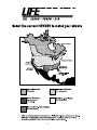
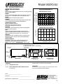
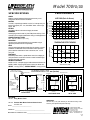
®
CLEAN • FRESH • AIR
OPERATION AND
INSTALLATION MANUAL
For Models:
500DCS ControlAir 15
850FD/DD Analog Controls
700FD/DD Analog Controls
1200FD/DD Analog Controls
500ERV ControlAir 15
700ERV Analog Controls
1200ERV Analog Controls
NOTE: ALTHOUGH SOME MODELS
DIFFER IN OPERATION, THE BASIC
STEPS ARE SIMILAR.
CAUTION
Before installation, careful consideration must be given to
how the system will operate if connected to any other piece
of mechanical equipment, i.e. a forced air furnace or air
handler, operating at a higher static. After installation, the
compatibility of the two pieces of equipment must be
confirmed, by measuring the airflow’s of the Heat/Energy
Recovery Ventilator (HRV/ERV), by using the balancing
procedure in this manual.
It is always important to assess how the operation of any
HRV/ERV may interact with vented combustion equipment
(ie. Gas Furnaces, Oil Furnaces, Wood Stoves, etc.).
NEVER install an HRV/ERV in a situation where its normal
operation, lack of operation or partial failure may result
in the backdrafting or improper functioning of vented
combustion equipment!!!
TO BE COMPLETED BY CONTRACTOR AFTER INSTALLATION
Installing Contractor
Telephone / Contact
Serial Number
Installation Date
Model
* LEAVE FOR HOMEOWNER
NOTE: Due to ongoing research and product development, specifications,
ratings and dimensions are subject to change without notice.
TI-72C-NE
0105
Table of Contents
INTRODUCTION
Introduction .................................................................... 2
ERV Questions and Answers ......................................... 3
Select Correct HRV/ERV to Match Climate.....................4
Select the Correct Size HRV/ERV ................................ 5
HRV - Aluminum Core
A Heat Recovery Ventilator (HRV) is designed to
provide fresh air into a building while exhausting
an equal amount of stale air. During the winter
months, the incoming cold fresh air is warmed by
utilizing the heat recovered from the stale air
before it is exhausted to the outdoors. During
summer months when the indoor space is air
conditioned, the Heat Recovery Ventilator will
help in cooling the incoming fresh air with the
stale air that is being exhausted.
Technical Data - Model 500DCS ................................... 6
Technical Data - Model 850FD/DD ............................... 7
Technical Data - Model 700FD/DD ............................... 8
Technical Data - Model 1200FD/DD ............................. 9
Technical Data - Model 500ERV ................................. 10
Technical Data - Model 700ERV ................................. 11
Technical Data - Model 1200ERV ............................... 12
Location for Mounting ................................................. 13
ERV - Enthalpic Paper Core
An Energy Recovery Ventilator (ERV) is designed
to provide fresh air into a building while
exhausting an equal amount of stale air. An ERV
is designed for use in warm humid areas with
heavy air conditioning use. The ERV will transfer
both sensible and latent heat from the incoming
fresh air to the outgoing stale air thereby reducing
the load (due to ventilation) on the air
conditioning system.
The Ductwork System ............................................. 13
Outside Weatherhoods ............................................... 14
Ducting from Weatherhoods ....................................... 14
Warmside Ducting - General ....................................... 14
Stale Air Return System ............................................. 14
Fresh Air Supply ......................................................... 15
The Integrated HVAC System ..................................... 15
Various Installation Types ........................................... 17
Electrical Connections ............................................. 18
Fan Defrost (700, 850, 1200) ...................................... 18
Damper Defrost (700, 850, 1200)................................. 18
Self Test of Defrost Systems (700, 850, 1200) ............ 18
ERVs are not suitable for climates where the
temperature drops below -4˚C (25˚F).
Speed Selection and Controls (700, 850, 1200) .......... 19
Optional Remote Controls (700, 850, 1200) ................ 19
ControlAir 15 (500 Only) ............................................. 20
Function And Control (500 Only) ................................ 21
Mode of Operation for ControlAir 15 (500 Only) ......... 22
Pitot Tube Air Flow Balancing ................................. 23
Service/Maintenance ................................................ 24
Motor ........................................................................... 24
HRV Core .................................................................... 24
ERV Core .................................................................... 24
Filters .......................................................................... 25
Condensate Drains ..................................................... 25
Duct Work ................................................................... 25
Damper Motor ............................................................. 25
Troubleshooting your HRV/ERV System ................ 26
Wiring Diagrams ............................................. 27-29
Warranty .................................................................... 30
2
ERV Questions & Answers
What is the difference between an HRV
and an ERV?
and damp situation. In fact, about 2/3 of the energy
used by the air conditioner system is to remove
moisture. Therefore, when ventilating in the summer,
less moisture brought into the home means less work
for the air conditioner, and energy savings for you.
The core in an HRV (Heat Recovery Ventilator)
transfers heat from one air stream to the other. This is
called sensible heat. The term ERV (Energy Recovery
Ventilator) is usually used to describe a unit with an
enthalpic core that transfers moisture as well as heat
from one air stream to the other. This (moisture
transfer) is called latent heat.
During the winter, an ERV recovers some humidity
from the exhaust air, reducing the need for humidification,
if the required ventilation rate would make the home
too dry.
Enthalpic - what does it mean?
Enthalpy is the term used to describe the energy
content of air. This energy is a combination of the
sensible and latent heat. Therefore, a core which
transfers energy is called an enthalpic core.
What's the difference between this type of
core and a rotary type?
Here's a list of characteristics of the fixed plate core.
1. No rotating parts, so maintenance is easy and the
unit lasts a long time.
2. It is very flexible in terms of installation.
3. The core can easily be changed.
4. Because the supply and exhaust air streams are
completely separate, there is very little cross
leakage of any dust or germs.
Is an ERV better than an HRV?
NOT NECESSARILY!! In cold climates such as most
of North America, an HRV works better than an ERV.
This is because the air inside the home during the
winter months will be more humid than the outside air.
An ERV would transfer the latent heat (humidity) from
the exhaust air back into the incoming airstream. This
will aggravate moisture problems in the home and
encourage the growth of mold and mildew. If the air in
the home is too dry for comfort, an ERV will not help. A
humidifier should be used to increase the humidity to
a comfortable level.
Can the core become clogged with dust?
Because the surface of the core is a turbulent flow
area, dust sticks to it easily; however, because the
inside of the element is a laminar flow area, virtually no
dust sticks to it.
Where do you use an ERV instead
of an HRV?
What is the maintenance?
About once a year you should use a vacuum cleaner
to remove the dust from the core's surface. DO NOT
WASH WITH WATER!!
An ERV is recommended for warm, humid areas with
heavy air conditioning use. As there is no defrost in an
ERV it is not recommended for areas where the
temperature drops below -4˚C (25˚F)
Is an air filter needed?
To prevent clogging of the core, an air filter should
always be installed on the supply and exhaust sides of
the core.
Why transfer moisture in the summer
(cooling season)?
The enthalpic core will allow moisture to be transferred
from a humid air flow to a dry air flow. This property is
useful in the cooling season if an air conditioning
system is used to lower the indoor humidity. You will
then have dry, cool air in the exhaust of the ERV, and
warm humid air in the supply stream. With these
conditions, the ERV will be able to transfer the
moisture and heat of the supply air to the exhaust air.
In this way, the ERV will supply to the home air which
is cooler and drier than outside. Remember that an
ERV is not a dehumidifier, and on its own will not take
moisture out of the air.
How much ventilation do I need?
During seasons when your windows and doors are
closed, the ERV should operate continuously when
the dwelling is occupied, and either continuously or
intermittently when not occupied.
For most installations the ERV will normally be set to
operate continuously on low speed with the option of
going to high speed as the need arises. For example;
if you are entertaining and there is a large number of
people present (some may be smoking), the unit
should be switched to high speed.
So why use an ERV?
A properly operating air conditioner will not only lower
the temperature in your house, but will also lower the
humidity level. This prevents an uncomfortable cold
Your ERV may be equipped with automatic or manual
switches, but all ERVs will have a manual speed
control override.
3
4
Selecting the Correct Size HRV/ERV
Commercial and Institutional Requirements
For outdoor air requirements, ASHRAE has produced the Ventilation Standard 62-1989 that
is used to determine acceptable ventilation rates. This standard is referenced directly or
used as “Good Engineering Practice” in most Code documents or design criteria.
Small restaurants, Donut Shops and Fast food stores
Seats
40
Employees
5
Total
45
ASHRAE requirement
20 cfm (10L/s) per person
Ventilation required
45 x 20 = 900 cfm (450 L/s)
Bank
Customers
25
Staff
9
Total
34
ASHRAE requirement
Ventilation required
20 cfm (10L/s) per person
34 x 20 = 680 cfm (320 L/s)
Bar or Tavern
Seats
50
Employees
7
Total
57
ASHRAE requirement
Ventilation required
Bingo Hall
Customers
180
Staff
20
Total
200
ASHRAE requirement
Ventilation required
30 cfm (15L/s) per person
200 x 30 = 6000 cfm (3000 L/s)
Print Shop, Duplicating
Square footage of shop
2000 square ft (m2)
30 cfm (15L/s) per person
57 x 30 = 1710 cfm (855 L/s)
Classroom and School Portables
Seats
29
Teacher
1
Total
30
ASHRAE requirement
15 cfm (7.5L/s) per person
Ventilation required
30 x 15 = 450 cfm (255 L/s)
Beauty Salon
Customers
12
Employees
6
Total
18
ASHRAE requirement
Ventilation required
ASHRAE requirement
0.5 cfm/ft2 (2.5L/s - m2)
per person
Ventilation required
2000 x 0.5 = 1000 cfm (500 L/s)
Swimming Pools
Refer to “Pool” Models Installation Manuals.
25 cfm (12.5L/s) per person
18 x 25 = 450 cfm (255 L/s)
MAKE UP HEAT REQUIREMENT at 1200 CFM (566L/s)
Outdoor Temp.
C°
F°
0
-10
-20
-30
-40
32
14
-4
-22
-40
Nominal
kW Req. for
20°C (68°F)
Air Delivery
7
10
12
15
17
5
Nominal
kW Req. for
25°C (77°F)
Air Delivery
Nominal
kW Req. for
30°C (86°F)
Air Delivery
10
14
15
19
21
14
17
19
22
24
Model 500DCS
SPECIFICATIONS
PERFORMANCE
282 (600)
235 (500)
94 (200)
25 (.1)
50 (.2)
75 (.3)
100 (.4)
125 (.5)
EXTERNAL STATIC PRESSURE IN PASCALS (in. W.C.)
TEMPERATURE EFFECTIVENESS
100%
90%
80%
NOTE: Exhaust Relative Humidity (RH) at 40%
94
(200)
190
(400)
143
(300)
MOUNTING POINTS
150 mm
(5 7/8")
475 mm
(18 3/4")
356 mm
(14")
1245 mm
(49")
DEFROST
FRONT VIEW
SUPPLY AIR
TO BUILDING
282
(600)
inches (mm)
475 mm
32 mm
(18 3/4") (1 1/4")
DRAIN CONNECTION
235
(500)
AIRFLOW IN L/s (CFM)
150 mm
(5 7/8")
SUPPLY AIR
FROM OUTSIDE
3.1 LOW
42 (100)
EXHAUST AIR
FROM BUILDING
NOTE:
Service clearance
is 760 mm (30 in.)
3.8 MED
4
3
2
1
143 (300)
DIMENSIONS 500DCS
EXHAUST AIR
TO OUTSIDE
6.3 HIGH
SPEED
5
190 (400)
TOTAL CURRENT DRAW (AMPS) @ 120 VAC
AIRFLOW L/s (CFM)
AIRFLOWS (Each Air Stream)
EFFECTIVENESS
CORES
Modular (4 section) patented aluminum heat recovery cores arranged
for high efficiency crossflow ventilation.
MOTORS
Two PSC, 5 speed double shafted, 120 VAC, 3.15 Amps each (6.3 total
on high speed). HP - 1/10, 1625 RPM. Watts - total on High Speed - 610.
FILTERS
Washable air filters in exhaust and supply air streams.
BLOWERS
Centrifugal type rated at 530 cfm (250 L/s) free air delivery. Each
air stream has two centrifugal blowers driven by two PSC motors.
CONNECTION DUCT SIZES
Four - 14" x 8" (356 mm x 200 mm).
MOUNTING
Unit to be set on support brackets hung by threaded rod type
apparatus (brackets and rods not included).
CASE
20 gauge prepainted galvanized steel (G60) for superior corrosion
resistance. Insulated with foil faced insulation duct liner where required to
prevent exterior condensation. Drain connection, One - 1/2" (12 mm) O.D.
CONTROLS ControlAir 15
DEFROST
Supply bypass damper routes indoor air to defrost cores.
WEIGHT 178 lbs. (81 kg) SHIPPING WEIGHT 203 lbs. (92 kg)
200 mm
(8")
35 mm
(1 3/8")
356 mm
(14")
200 mm
(8")
717 mm
(28 1/4 ")
717 mm
(28 1/4")
INTERIOR DUCT
EXTERIOR DUCT
CONNECTION SIDE
CONNECTION SIDE
OPTIONS
99-104
99-105
Digital Electronic Timer - 20/40/60 min. (3 wire)
Programmable Ventilation Control
includes Programmable Time Clock, Dehumidistat
and Air Sentry™
99-109 Air Sentry™ Air Quality Monitor designed to accept
remotely mounted Control Pad
99-250 Ventilation Dehumidistat - Dehumidistat designed
to accept remotely mounted Control Pad.
All units conform to CSA and UL standards.
WARRANTY
Units carry a 15 year warranty on the heat recovery core and
a 2 year replacement parts warranty.
DATE: __________________________
511 McCormick Blvd.
PROJECT: ________________________________________
MECHANICAL CONTRACTOR: ________________________________
6
London, Ontario N5W 4C8
Ph: (519) 457-1904
Fx: (519) 457-1676
Email: [email protected]
Website: www.lifebreath.com
TI-110-NE
0011
Model 850FD/DD
SPECIFICATIONS
PERFORMANCE
CORES
Modular (6 section) patented aluminum heat recovery cores arranged for high
efficiency crossflow ventilation.
MOTORS
Two PSC, 3 speed double shafted, 120 VAC, 3.95 Amps each (7.9 total on
high speed). HP - 1/4, 1625 RPM. Watts - total on High Speed - 848.
FILTERS
Washable air filters in exhaust and supply air streams.
BLOWERS
Centrifugal type rated at 950 cfm (448 L/s) free air delivery. Each air stream
has one double shafted motor driving two centrifugal blowers.
CONNECTION DUCT SIZES
Three - 20" x 8" (508 mm x 200 mm).
Stale air intake - 26" x 8" (660 mm x 200 mm).
Model 850DD - additional 20" X 8" defrost port
MOUNTING
Unit to be set on support brackets hung by threaded rod type apparatus.
(brackets and rods not provided).
CASE
20 gauge prepainted galvanized steel (G60) for superior corrosion
resistance. Insulated with foil faced insulation where required to prevent
exterior condensation. Drain connections, Two - 1/2" (12 mm) O.D.
CONTROLS
Illuminated power switch, 3 speed blower control, low voltage (24 VAC)
terminals for connection of remote controls and defrost light indicating
automatic operation.
DEFROST CONTROLS
Model 850FD - Interrupts supply air while exhaust air defrosts core.
Model 850DD - Supply bypass routes indoor air to defrost core.
WEIGHT 255 lbs. (116 kg) SHIPPING WEIGHT 280 lbs. (127 kg)
EXHAUST AIR
TO OUTSIDE
AIRFLOW L/s (CFM)
329 (700)
DRAIN CONNECTION
7.0 MED
SPE
ED
6.6 LOW
190 (400)
143 (300)
94 (200)
25 (.1)
50 (.2) 75 (.3) 100 (.4) 125 (.5) 150 (.6) 175 (.7)
EFFECTIVENESS
TEMPERATURE EFFECTIVENESS
90%
80%
70%
NOTE: Exhaust Relative Humidity (RH) at 40%
235
(500)
282
(600)
329
(700)
378
(800)
425
(900)
AIRFLOW IN L/s (CFM)
mm (inches)
MOUNTING POINTS
263 mm
(10 3/8")
660 mm
(26")
190 mm
(7 1/2 ")
263 mm
(10 3/8 ")
172 mm
(6 3/4")
1188 mm
(46 3/4")
7.9 HIGH
ED
235 (500)
508 mm
(20")
DD MODELS ONLY
LOW
282 (600)
EED
SPE
CONTROLS
NOTE:
Service clearance
is 760 mm (30 in.)
DEFROST AIR
H SP
MED
EXTERNAL STATIC PRESSURE IN PASCALS (in. W.C.)
200 mm
( 8")
SUPPLY AIR
FROM OUTSIDE
HIG
378 (800)
42 (100)
DIMENSIONS 850
EXHAUST AIR
FROM BUILDING
425 (900)
TOTAL CURRENT DRAW (AMPS) @ 120 VAC
AIRFLOWS (Each Air Stream)
475 (1000)
200 mm
(8")
625 mm
(24 5/8")
508 mm
(20")
200 mm
(8")
508 mm
(20")
200 mm
(8")
149 mm
(5 7/8")
1055 mm
(41 1/2")
SUPPLY AIR
TO BUILDING
FRONT VIEW
OPTIONS
99-101 Sixty Minute Timer
INTERIOR DUCT
EXTERIOR DUCT
CONNECTION SIDE
CONNECTION SIDE
All units conform to CSA and UL standards
WARRANTY
99-130
Remote Wall Mount Dehumidistat Control
24 VAC only
All units carry a 15 year warranty on the heat recovery cores
and a 2 year replacement parts warranty.
DATE: __________________________
511 McCormick Blvd.
London, Ontario N5W 4C8
PROJECT: ________________________________________
MECHANICAL CONTRACTOR: ________________________________
7
Ph: (519) 457-1904
Fx: (519) 457-1676
Email: [email protected]
Website: www.lifebreath.com
TI-111
0011
Model 700FD/DD
SPECIFICATIONS
SUPPLY AIR
FROM OUTSIDE
DD MODEL ONLY
AIRFLOWS (Each Air Stream)
423 (900)
AIRFLOW L/s (CFM)
378 (800)
329 (700)
5.5 HIGH
282 (600)
HIGH SPEED
235 (500)
MED SPEED
190 (400)
LOW SPEED
143 (300)
94 (200)
42 (100)
25 (.1) 50 (.2)
75 (.3) 100 (.4) 125 (.5) 150 (.6) 175 (.7)
5.0 MED
4.7 LOW
EXTERNAL STATIC PRESSURE IN PASCALS (IN. W.C.)
TEMPERATURE EFFECTIVENESS
EFFECTIVENESS
CORES
Modular (2 section) patented aluminum heat recovery cores
arranged for efficient cross-flow ventilation.
MOTORS
Two PSC, 3 speed single shafted, 120 VAC, 2.75 Amps each (5.5
total on high speed). HP - 1/10, 1625 RPM. Watts - total on high
speed - 648.
FILTERS
Washable air filters in exhaust and supply air streams.
BLOWERS
Centrifugal type rated at 329 L/s (700 CFM) free air delivery. Each
air stream has one single shafted motor driving a centrifugal blower.
CONNECTION DUCT SIZES
Four - 356 mm x 200 mm (14" x 8" ).
MOUNTING
Unit to be set on support brackets hung by threaded rod type
apparatus (brackets and rods not provided).
CASE
20 gauge prepainted galvanized steel (G60) for superior corrosion
resistance. Insulated with foil faced insulation where required to
prevent exterior condensation. Drain connections; two - 12 mm
(1/2") O.D.
CONTROLS
Illuminated power switch, 3 speed blower control, low voltage (24
VAC) terminals for connection of remote controls and defrost light
indicating automatic operation.
DEFROST CONTROLS
MODEL 700 FD - Interrupts supply air while exhaust air defrosts core.
MODEL 700DD - Supply bypass routes indoor air to defrost core.
WEIGHT 64.4 kg (142 lbs.) SHIPPING WEIGHT 75.8 kg (167 lbs.)
TOTAL CURRENT DRAW (AMPS) @ 120 VAC
PERFORMANCE
MODEL
700FD, 700DD
70%
60%
50%
NOTE: Exhaust Relative Humidity (RH) at 40%
190
(400)
143
(300)
235
(500)
329
(700)
282
(600)
AIRFLOW IN L/s (CFM)
DIMENSIONS 700 mm (inches)
MOUNTING POINTS
CONTROLS
EXHAUST AIR
TO OUTSIDE
356 mm
(14")
165 mm
(6 1/2")
165 mm
(6 1/2")
356 mm
(14")
FD MODEL ONLY
625 mm
(24 5/8 ")
NOTE:
Service clearance
is 760 mm (30 in.)
from front
access doors
210 mm
(8 1/4")
200 mm
(8")
¤
HEAT RECOVERY VENTILATORS (HRVs)
EXHAUST AIR
FROM BUILDING
DRAIN CONNECTION
SUPPLY AIR
TO BUILDING
730 mm
(28 3/4")
753 mm (29 5/8")
FRONT VIEW
DISCHARGE SIDE
OPTIONS
99-101 Sixty Minute Timer
99-130
159 mm
(6 1/4")
200 mm
(8")
730 mm
(28 3/4")
INLET SIDE
All units conform to CSA and UL standards.
WARRANTY
All units carry a 15 year warranty on the heat recovery cores
and a 2 year replacement parts warranty.
Remote Wall Mount Dehumidistat Control
24 VAC only
DATE: __________________________
511 McCormick Blvd.
London, Ontario N5W 4C8
PROJECT: ________________________________________
MECHANICAL CONTRACTOR: ________________________________
8
Ph: (519) 457-1904
Fx: (519) 457-1676
Email: [email protected]
Website: www.lifebreath.com
TI-103
0011
Model 1200FD/DD
PERFORMANCE
SPECIFICATIONS
SUPPLY AIR
FROM OUTSIDE
613 (1300)
566 (1200)
8.1 HIGH
518 (1100)
HIGH SPEED
7.8 MED
MED SPEED
7.1 LOW
472 (1000)
423 (900)
378 (800)
329 (700)
LOW SPEED
282 (600)
235 (500)
25 (.1) 50 (.2) 75 (.3) 100 (.4) 125 (.5) 150 (.6) 175 (.7)
EXTERNAL STATIC PRESSURE IN PASCALS (in. W.C.)
TOTAL CURRENT DRAW (AMPS) @ 120 VAC
AIRFLOW L/s (CFM)
AIRFLOWS (Each Air Stream)
TEMPERATURE EFFECTIVENESS
EFFECTIVENESS
CORES
Modular (3 section) patented aluminum heat recovery cores arranged
for efficient cross-flow ventilation.
MOTORS
Two PSC, 3 speed double shafted, 120 VAC, 4 Amps each (8.1 total on
high speed). HP - 1/4, 1625 RPM. Watts - total on high speed - 972.
FILTERS
Washable air filters in exhaust and supply air streams.
BLOWERS
Centrifugal type rated at 1200 cfm (566 L/s) free air delivery. Each air
stream has one double shafted motor driving a centrifugal blower.
CONNECTION DUCT SIZES
Four - 20" x 8" (508 mm x 200 mm).
MOUNTING
Unit to be set on support brackets hung by threaded rod type
apparatus. (brackets and rod not provided).
CASE
20 gauge prepainted galvanized steel (G60) for superior corrosion
resistance. Insulated with foil faced insulation where required to
prevent exterior condensation. Drain connections; two - 1/2" (12 mm) O.D.
CONTROLS
Illuminated power switch, 3 speed blower control, low voltage (24
VAC) terminals for connection of remote controls and defrost light
indicating automatic operation.
DEFROST CONTROLS
MODEL 1200FD - Interrupts supply air while exhaust air defrosts core.
MODEL 1200DD - Supply bypass routes indoor air to defrost core.
WEIGHT 191 lbs. (87 kg) SHIPPING WEIGHT 215 lbs. (98 kg)
70%
60%
50%
NOTE: Exhaust Relative Humidity (RH) at 40%
235
(500)
282
(600)
329
(700)
378
(800)
423
(900)
472
(1000)
518
(1100)
566
(1200)
AIRFLOW IN L/s (CFM)
DIMENSIONS 1200 mm (inches)
DD MODEL ONLY
EXHAUST AIR
TO OUTSIDE
MOUNTING POINTS
CONTROLS
508 mm
(20")
FD MODEL ONLY
263 mm
263 mm
(10 3/8")
(10 3/8")
172 mm
(6 3/4")
NOTE:
Service clearance
is 760 mm (30 in.)
from front
access doors
200 mm
(8")
¤
625 mm
(24 5/8 ")
508 mm
(20")
149 mm
(5 7/8")
200 mm
(8")
HEAT RECOVERY VENTILATORS (HRVs)
EXHAUST AIR
FROM BUILDING
DRAIN CONNECTION
759 mm (29 7/8")
FRONT VIEW
SUPPLY AIR
TO BUILDING
1055 mm
(41 1/2")
DISCHARGE SIDE
1055 mm
(41 1/2")
INLET SIDE
OPTIONS
All units conform to CSA and UL standards
99-101
Sixty Minute Remote Timer
WARRANTY
99-130
All units carry a 15 year warranty on the heat recovery cores
and a 2 year replacement parts warranty.
Remote Wall Mount Dehumidistat Control
24 VAC only
DATE: __________________________
511 McCormick Blvd.
London, Ontario N5W 4C8
PROJECT: ________________________________________
MECHANICAL CONTRACTOR: ________________________________
9
Ph: (519) 457-1904
Fx: (519) 457-1676
Email: [email protected]
Website: www.lifebreath.com
TI-120
0011
®
Model 500ERV
CLEAN • FRESH • AIR
PERFORMANCE
SPECIFICATIONS
AIRFLOW L/s (CFM)
282 (600)
235 (500)
6.3 HIGH
SPEED
5
190 (400)
3.8 MED
4
3
2
1
143 (300)
94 (200)
3.1 LOW
42 (100)
25 (.1)
50 (.2)
75 (.3)
100 (.4)
125 (.5)
EXTERNAL STATIC PRESSURE IN PASCALS (in. W.C.)
TOTAL CURRENT DRAW (AMPS) @ 120 VAC
AIRFLOWS (Each Air Stream)
LATENT RECOVERY (MOISTURE) TRANSFER CORES
Modular (4 section) 2- Enthalpic, 2 Aluminum arranged for high
efficiency crossflow ventilation.
MOTORS - Two PSC, 5 speed double shafted, 120 VAC, 3.15 Amps
each (6.3 total on high speed). HP - 1/10, 1625 RPM. Watts - total on
High Speed - 610.
FILTERS - Washable air filters in exhaust and supply air streams.
BLOWERS - Centrifugal type rated at 530 cfm (250 L/s) free air
delivery. Each air stream has two centrifugal blowers driven by two
PSC motors.
CONNECTION DUCT SIZES Four - 14" x 8" (356 mm x 200 mm).
MOUNTING - Unit to be set on support brackets hung by threaded
rod type apparatus (brackets and rods not included).
DEFROST - Damper defrost system.
CASE - 20 gauge prepainted galvanized steel (G60) for superior
corrosion resistance. Insulated with foil faced insulation duct liner
where required to prevent exterior condensation. Drain connection,
One - 1/2" (12 mm) O.D.
CONTROLS - ControlAir 15
WEIGHT 178 lbs. (81 kg) SHIPPING WEIGHT 203 lbs. (92 kg)
EFFECTIVENESS
TEMPERATURE EFFECTIVENESS
100%
90%
80%
NOTE: Exhaust Relative Humidity (RH) at 40%
94
(200)
143
(300)
190
(400)
235
(500)
282
(600)
AIRFLOW IN L/s (CFM)
DIMENSIONS 500ERV inches (mm)
EXHAUST AIR
TO OUTSIDE
ENTHALPIC CORE
ALUMINUM CORE
EXHAUST AIR
FROM BUILDING
MOUNTING POINTS
5 7/8"
(150 mm)
5 7/8"
(150 mm)
NOTE:
Service clearance
is 30 in. (760 mm)
18 3/4"
(475 mm)
18 3/4"
(475 mm)
1 1/4"
(32 mm)
14"
(356 mm)
SUPPLY AIR
FROM OUTSIDE
DEFROST
49"
(1245 mm)
DRAIN CONNECTION
FRONT VIEW
SUPPLY AIR
TO BUILDING
OPTIONS
99-104
99-105
99-109
8"
(200 mm)
1 3/8"
(35 mm)
14"
(356 mm)
8"
(200 mm)
28 1/4 "
(717 mm)
28 1/4"
(717 mm)
INTERIOR DUCT
EXTERIOR DUCT
CONNECTION SIDE
CONNECTION SIDE
All units conform to CSA and UL standards.
WARRANTY
Digital Electronic Timer - 20/40/60 min. (3 wire)
Programmable Ventilation Control includes
Programmable Time Clock, Dehumidistat and
Air Sentry™
Air Sentry™ Air Quality Monitor designed to
accept remotely mounted Control Pad
Units carry a 5 year warranty on the energy recovery cores,
a 15 year warranty on aluminum cores and a 2 year
replacement parts warranty.
ERVs are not recommended for regions where the
design temperature is below 25°F (-4°C)
DATE: __________________________
511 McCormick Blvd.
London, Ontario N5W 4C8
PROJECT: ________________________________________
MECHANICAL CONTRACTOR: ________________________________
10
Ph: (519) 457-1904
Fx: (519) 457-1676
Email: [email protected]
Website: www.lifebreath.com
TI-130
0105
®
Model 700ERV
CLEAN • FRESH • AIR
SPECIFICATIONS
AIRFLOWS (Each Air Stream)
LATENT RECOVERY (MOISTURE) TRANSFER CORES
Modular (2 section) enthalpic (moisture) transfer cores
arranged for efficient cross-flow ventilation.
AIRFLOW L/s (CFM)
423 (900)
MOTORS
Two PSC, 3 speed single shafted, 120 VAC, 2.75 Amps each
(5.5 total on high speed). HP - 1/10, 1625 RPM. Watts - total
on high speed - 648.
FILTERS
Washable air filters in exhaust and supply air streams.
378 (800)
329 (700)
5.5 HIGH
282 (600)
HIGH SPEED
235 (500)
MED SPEED
190 (400)
LOW SPEED
5.0 MED
4.7 LOW
143 (300)
94 (200)
42 (100)
BLOWERS
Centrifugal type rated at 700 CFM (329 L/s) free air delivery.
Each air stream has one single shafted motor driving a
centrifugal blower.
25 (.1) 50 (.2)
75 (.3) 100 (.4) 125 (.5) 150 (.6) 175 (.7)
TOTAL CURRENT DRAW (AMPS) @ 120 VAC
PERFORMANCE
EXTERNAL STATIC PRESSURE IN PASCALS (IN. W.C.)
TEMPERATURE EFFECTIVENESS
CONNECTION DUCT SIZES
Four - 14" x 8" (356 mm x 200 mm)
EFFECTIVENESS
MOUNTING
Unit to be set on support brackets hung by threaded rod type
apparatus (brackets and rods not provided).
CASE
20 gauge prepainted galvanized steel (G60) for superior
corrosion resistance. Insulated with foil faced insulation
where required to prevent exterior condensation.
70%
60%
50%
NOTE: Exhaust Relative Humidity (RH) at 40%
CONTROLS
Illuminated power switch, 3 speed blower control, low voltage
(24 VAC) terminals for connection of remote controls.
190
(400)
143
(300)
235
(500)
282
(600)
329
(700)
AIRFLOW IN L/s (CFM)
WEIGHT 142 lbs (64.4 kg) SHIPPING WEIGHT 167 lbs. (75.8 kg)
DIMENSIONS 700ERV inches (mm)
SUPPLY AIR
FROM OUTSIDE
ENTHALPIC CORE
EXHAUST AIR
TO OUTSIDE
MOUNTING POINTS
CONTROLS
14"
(356 mm)
NOTE:
Service clearance
is 30 in. (760 mm)
24 5/8 "
(625 mm)
8 1/4"
(210 mm)
8"
(200 mm)
¤
EXHAUST AIR
FROM BUILDING
HEAT RECOVERY VENTILATORS (HRVs)
29 5/8"
(753 mm)
6 1/2"
(165 mm)
SUPPLY AIR
TO BUILDING
28 3/4"
(730 mm)
FRONT VIEW
DISCHARGE SIDE
6 1/2"
(165 mm)
14"
(356 mm)
6 1/4"
(159 mm)
8"
(200 mm)
28 3/4"
(730 mm)
INLET SIDE
OPTIONS
WARRANTY
99-101
Units carry a 5 year warranty on the energy recovery cores
and 2 year replacement parts warranty.
Sixty Minute Remote Timer
ERVs are not recommended for regions where the design
temperature is below 25°F (-4°C)
All units conform to CSA and UL standards.
DATE: __________________________
511 McCormick Blvd.
London, Ontario N5W 4C8
PROJECT: ________________________________________
MECHANICAL CONTRACTOR: ________________________________
11
Ph: (519) 457-1904
Fx: (519) 457-1676
Email: [email protected]
Website: www.lifebreath.com
TI-131
0105
®
Model 1200ERV
CLEAN • FRESH • AIR
SPECIFICATIONS
PERFORMANCE
LATENT RECOVERY (MOISTURE) TRANSFER CORES
Modular (3 section) latent recovery (moisture) transfer cores
arranged for efficient cross-flow ventilation.
MOTORS
Two PSC, 3 speed double shafted, 120 VAC, 4 Amps each
(8.1 total on high speed). HP - 1/4, 1625 RPM. Watts - total
on high speed - 972.
FILTERS
Washable air filters in exhaust and supply air streams.
BLOWERS
Centrifugal type rated at 1200 cfm (566 L/s) free air delivery.
Each air stream has one double shafted motor driving a
centrifugal blower.
CONNECTION DUCT SIZES
Four - 20" x 8" (508 mm x 200 mm).
MOUNTING
Unit to be set on support brackets hung by threaded rod type
apparatus. (brackets and rod not provided).
CASE
20 gauge prepainted galvanized steel (G60) for superior
corrosion resistance. Insulated with foil faced insulation
where required to prevent exterior condensation.
CONTROLS
Illuminated power switch, 3 speed blower control, low voltage
(24 VAC) terminals for connection of remote controls.
WEIGHT 191 lbs. (87 kg) SHIPPING WEIGHT 215 lbs. (98 kg)
613 (1300)
566 (1200)
8.1 HIGH
518 (1100)
HIGH SPEED
7.8 MED
MED SPEED
7.1 LOW
472 (1000)
423 (900)
378 (800)
329 (700)
LOW SPEED
282 (600)
235 (500)
25 (.1) 50 (.2) 75 (.3) 100 (.4) 125 (.5) 150 (.6) 175 (.7)
EXTERNAL STATIC PRESSURE IN PASCALS (in. W.C.)
TOTAL CURRENT DRAW (AMPS) @ 120 VAC
AIRFLOW L/s (CFM)
AIRFLOWS (Each Air Stream)
EFFECTIVENESS
TEMPERATURE EFFECTIVENESS
70%
60%
50%
NOTE: Exhaust Relative Humidity (RH) at 40%
235
(500)
282
(600)
329
(700)
378
(800)
423
(900)
472
(1000)
518
(1100)
566
(1200)
AIRFLOW IN L/s (CFM)
DIMENSIONS 1200ERV inches (mm)
ENTHALPIC CORE
EXHAUST AIR
TO OUTSIDE
SUPPLY AIR
FROM OUTSIDE
CONTROLS
20"
(508 mm)
10 3/8"
10 3/8"
(263 mm)
(263 mm)
NOTE:
6 3/4"
(172 mm)
Service clearance
is 30 in. (760 mm)
from front
access doors.
8"
(200 mm)
¤
EXHAUST AIR
FROM BUILDING
24 5/8 "
(625 mm)
20"
(508 mm)
5 7/8"
(149 mm)
8"
(200 mm)
HEAT RECOVERY VENTILATORS (HRVs)
29 7/8"
(759 mm)
FRONT VIEW
SUPPLY AIR
TO BUILDING
41 1/2"
(1055 mm)
DISCHARGE SIDE
41 1/2"
(1055 mm)
INLET SIDE
OPTIONS
WARRANTY
99-101
Units carry a 5 year warranty on the energy recovery cores
and 2 year replacement parts warranty.
Sixty Minute Remote Timer
ERVs are not recommended for regions where the design
temperature is below 25°F (-4°C)
All units conform to CSA and UL standards.
DATE: __________________________
511 McCormick Blvd.
London, Ontario N5W 4C8
PROJECT: ________________________________________
MECHANICAL CONTRACTOR: ________________________________
12
Ph: (519) 457-1904
Fx: (519) 457-1676
Email: [email protected]
Website: www.lifebreath.com
TI-132
0105
Location for Mounting
The Ductwork System
The HRV/ERV must be located in a conditioned
space where the surrounding air temperature
does not fall below 60˚F (16˚C). The unit must be
mounted level (horizontal). The warranty will be
void if these conditions are not met.
A properly designed ducting system will allow the
HRV/ERV to operate at its maximum efficiency.
(Air flow will be restricted by undersized ducting,
use of too many elbows, tees, bends, etc.).
Always try to keep duct runs as short and
straight as possible.
Typically the HRV/ERV is positioned close to
an outside wall or the roof to simplify the
connections and keep the length of insulated
ducting required for the fresh air intake to a
minimum.
NOTE: Fully insulated ducting with an integral
vapour barrier must be used on all runs
passing through unheated areas in order
to avoid condensation problems and
energy losses from the air steams.
A minimum clearance of 36 inches (90 cm) in
front of the HRV/ERV is recommended to service
the ventilator. The HRV/ERV may be mounted on
an equipment platform providing the drain hoses
are clear and there is sufficient space to open the
doors for servicing.
All joints must be airtight, sealed and impervious
to moisture. See specification sheets for each
unit for exact duct sizes and location.
To minimize pressure drop and noise, galvanized
metal ducts, properly sized, are recommended.
Keep ducting as short as possible and use a
minimum of elbows and tees. Connecting sections
and shorter runs may be flexible ducting one size
larger than the metal equivalent. Use flexible duct
connectors at the HRV/ERV to avoid noise
transmission.
Install the drain pans in the bottom of the
HRV/ERV so the drain (not on all models)
connections protrude through the holes provided.
Use drain hoses with hose clamps to connect the
drain pan outlets to a floor drain or standpipe.
Make sure the drain line slopes down to the
outlet. If this is not possible a condensate pump
will be required for positive removal of the water.
Protect the drain line from freezing.
All duct joints must be secured with screws,
rivets or duct sealant and sealed with aluminum
duct tape to prevent leakage.
HRV CABINET
DRAIN
SPOUT
DRAIN
SPOUT
TAPE
TEE
CONNECTOR
TO DRAIN
Forming the “P” Trap
13
Outside Weatherhoods
The weatherhoods must have built-in “bird” screen with
1/4 in (63.5 mm) minimum mesh to prevent birds and
rodents from entering into the ductwork. Do not use
smaller mesh as it will be very susceptible to plugging
up. Gravity dampers at the vents must not be used as
they will restrict air flow and often “seize up”. The
preferred location of the outside weatherhoods is:
All duct joints must be fastened with screws, rivets or
duct sealant and wrapped with a quality duct tape to
prevent leakage. We recommend aluminum foil tape.
Stale Air Return System
The stale air return system is used to draw air from the
points in the building where the worst air quality
problems occur. Balancing dampers and/or adjustable
grilles are recommended on all return air lines which
are used during installation to help balance the “draw”
from different areas of the building.
• no less than 10 ft. (3 m) apart from each other
• at least 18 in ( 46 cm) above snow line or
ground level
• away from sources of contaminants, such as
automobile exhaust fumes, gas meters,
garbage cans, containers, etc.
• not exposed to prevailing winds, whenever
reasonable possible
Alternately, the stale air may be drawn directly from
the return air duct. When this system is used, the air
handler’s blower must constantly operate. The exhaust
takeoff connection must be at least a 3 ft (1 m) from
a directly connected HRV/ERV supply duct if both are
connected to the same duct run. Static pressure of the
air handlers return system should be noted and
compensated for if, it is apparent that the static
pressure of the return in the air handler will exceed
.1 to .15” W.C.
The outside perimeter of the weatherhood must be
caulked to prevent leakage into the building.
The design and size of the weatherhoods or louvres
chosen by the installer must allow for adequate free
area. Water and debris penetration of the system is
minimized when the airflow does not exceed 1000 FPM
(5.08 m/s) free area velocity.
Ducting from the Weatherhoods
A damper located just prior to the HRV/ERV is
required to balance the stale air exhausted with the
fresh air supply entering the building.
Galvanized sheet metal ducting with sufficient cross
section with an integral single piece vapour barrier should
be used to connect the HRV/ERV to the weatherhoods.
All ducting must meet UL Class 1 requirements.
Return air suction points should be located on the
opposite side of the room from the fresh air inlet. The
inlets may be located in the ceiling or high on the walls
and fitted with inlet grilles.
A minimum R value of insulation should be equal to
4 (RSI 0.75)
Many commercial activities produce air contaminants in
the form of dusts, fumes, mists, vapours and gases.
Contaminants should be controlled at the source so that
they are not dispersed through the building nor allowed
to increase to toxic concentration levels. The ventilator
allows for economical operation of the HVAC system
while effectively removing contaminants from the space.
In designing the exhaust portion of the system
the exhaust grilles are placed so as to remove the
contaminants while not allowing them to enter the
breathing zone of the occupants.
A good bead of high quality caulking (preferably acoustical sealant) and taping with a high quality aluminum foil
tape is recommended to seal the duct to both the
HRV/ERV and the weatherhood.
Warmside Ducting - General
Ducting from the HRV/ERV to the different areas in the
building should be galvanized metal whenever possible.
For contaminants that are lighter than air, grilles should
be located high on the wall. If contaminants are heavier
than air, a lower placement of the grilles will be
required. Information on a contaminants specific gravity
and toxicity should be available from chemical data
sheets.
To minimize airflow losses in the ductwork system, all
ducts should be as short as possible and with as few
bends or elbows as possible. 45° elbows are preferred
to 90° elbows. Use “Wye” (Y) fittings instead of “Tees”
(T) whenever possible.
14
Fresh Air Supply System
The Integrated HVAC System
Figure A and B
The fresh air supply ductwork from the HRV/ERV may
be directly connected to the return air duct of the
forced air system. Check the air flow balance of the
HRV/ERV with the air handler blower both “ON” and
“OFF” to determine that it does not imbalance the
HRV/ERV more than 10%. Also, it is advisable to
include a short length of flex duct or other non-metallic
connector in this hard ducted line in order to keep
the HRV/ERV acoustically isolated and separately
grounded (electrically) from the air handler. This will
avoid a possible shock hazard to service people if a
short to ground develops in one of the devices.
The HRV/ERV has become an integral component of
the HVAC system. Figure A shows an HRV/ERV unit
providing fresh air directly to the return air plenum of a
rooftop heat/cool unit.
In the balanced airflow system, the HRV/ERV exhaust
removes stale room air (eg. from lunch room, storage
or copy area) and returns to the space an equal
amount of fresh outdoor air, making the use of an
economizer obsolete in conjunction with an HRV/ERV.
Many buildings have ceiling return air plenum as
in Figure B. Fresh air from the HRV/ERV can be
introduced directly into the ceiling space but this
should occur near the air handler’s intake.
It may be necessary to install a separate fresh air supply
ductwork system if the heating is other than forced air.
When installing an HRV/ERV, the designer and
installer should be aware of local codes that may
require smoke detectors and/or firestats in the HVAC
or HRV/ERV ductwork.
By operating the HRV/ERV on a 24 hour/7 day battery
backed timer, the unit can be set to operate only when
occupancy or indoor conditions require the air
exchange.
Because an HRV/ERV is designed to bring fresh air
into the building, structures may require supply voltage
interrupt when smoke or flame sensors are triggered,
or when a central fire alarm system is activated.
In installations where it is satisfactory to provide
general exhaust from the space, the air to be
exhausted may be taken directly from the return air
plenum to the HRV/ERV as it is drawn back to the air
handler. Fresh air supplied by the HRV/ERV is then
introduced directly into the return air plenum but at a
location closer to the air handler. The air handler
would have a constant running blower to effectively
distribute the fresh air and remove the stale air.
Balancing dampers would be located in both the
HRV/ERV supply and exhaust ducts between the
return air plenum and the HRV/ERV.
Supply air grilles may be ceiling or high wall mounted.
Avoid locating incoming fresh air grilles that could
cause a direct draft on the occupants as the incoming
air may be below room temperature. A reheat duct
heater can be installed to improve occupant comfort.
The use of balancing dampers or adjustable grilles to
balance the flow rates into various rooms is
recommended.
The use of balancing dampers or adjustable grilles
as supply air diffusers and air exhaust covers are
recommended. TECHGRILLES™ are round, efficient,
sound absorbing devices available in 4”, 5”, 6” and 8”
(100, 125, 150, and 200 mm) models.
NOTE: At no time should the air handler T.E.S.P. on
the return duct exceed that of the HRV/ERV .
AIR FLOW
SUPPLY
TECHGRILLE
(optional)
schematic
AIR FLOW
EXHAUST
15
The Integrated HVAC System
ECONOMIZER
ROOFTOP
UNIT
SUPPLY DUCT
RETURN AIR DUCT or
BREATHER T
FRESH AIR
SUPPLY
B.D.
HRV/ERV UNIT
B.D.
STALE AIR
EXHAUST
HRV/ERV FRESH
AIR SUPPLY
STALE AIR
EXHAUST TO HRV/ERV
Figure A
Example only - Duct connections not typical
ECONOMIZER
ROOFTOP
UNIT
ROOF DECK
CEILING RETURN AIR PLENUM
FRESH AIR
SUPPLY
12" BREATHER
SPACE
SUPPLY DUCTWORK
B.D.
HRV/ERV UNIT
B.D.
STALE AIR
EXHAUST
HRV/ERV FRESH
AIR SUPPLY
STALE AIR EXHAUST
Example only - Duct connections not typical
Figure B
16
Various Installation Types
NOTE:
Figure 7A
Saddle Installation
When installing your HRV/ERV
flexible duct connectors should
be installed between the HRV/ERV
and the galvanized duct work.
Vibration Isolators
(Supplied by others)
Threaded
rod and U channel
(Supplied by others)
Hang unit with suspended rods
and "U" channel members.
Figure 7B
Curb Mounted
Curb is wood or metal
(Supplied by others)
Mount unit on wooden or metal
curb assembly. Unit must be raised
an adequate height for installation
and slope of drain lines.
Figure 7C
Suspended
May be anchored to
floor,leaving space
for drain connections
PVC Support Straps
(Supplied by others)
Unit Suspended using
Polyester reinforced PVC support straps.
17
Vibration Isolators
(Supplied by others)
Electrical Connections
accumulation. After the defrost period, the fresh air
supply fan automatically returns to the normal speed
and fresh outside air continues to be drawn into the
building. Water from the melted frost collects in the
bottom drip pans and drains out through the bottom
drain connections. The defrost cycle repeats
automatically until the air temperature rises
above 27˚F(-3˚C).
It is recommended that a licensed electrician make all
electrical connections. It is very important that the
unit be properly grounded. It is recommended that a
separate 15 amp/120 volt circuit be used.
WARNING: In order to prevent electric shock when
cleaning or servicing the HRV/ERV, it is extremely
important to confirm the polarity of the power line that is
switched by the safety (disconnect) switch whose control
arm is located on the outside of the electrical control box
area. The hot line (black) is the proper line to be switched.
To confirm the proper polarity, use a voltmeter or test lamp
to make sure there is no power after the switch when the
door is open. Check between that point and ground (on the
cabinet). This must be done as occasionally some
buildings are improperly wired. Always make sure the
HRV/ERV is properly grounded.
DAMPER DEFROST
Models 700DD, 850DD, 1200DD
These damper defrost HRV’s have an electronically
controlled damper defrost mechanism. If the outside
temperature drops below 27˚F(-3˚C ), the defrost timer
is activated. A motor driven damper door mechanism
opens the defrost port and at the same time closes off
the supply air from outside. After approximately 3
minutes, the damper operates in the opposite direction
to close off the defrost port and reopen the fresh air at
the supply port. The 27.5 minute wait time and 3
minute defrost cycle repeat until the temperature again
rises above 27˚F (-3˚C).
Black
Neut.
een
Black
Power Supply
Cord
White
Self Test of Defrost Systems
Gr
Line
Power
Terminal
Block.
Models 700, 850, 1200
GND.
If confirmation of the defrost system is needed,
complete the following steps.
1. Disconnect power to the unit and open access/
maintenance doors.
2. Locate the “snap disc” type temperature sensor
mounted in the upper left hand corner (cold air
stream) of the HRV.
3. Disconnect the two wires from the HRV to the
sensor, at the sensor.
4. Using a jump wire with alligator clips, join two
wires from the HRV together.
5. Close access doors and power the unit.
Electrical Connection
FAN DEFROST
Models 700FD, 850FD, 1200FD
Fan defrost HRV’s are equipped with an electronically
controlled fan defrost system to remove frost that
collects on the warm air side of the aluminum heat
transfer surfaces of the heat exchanger core. When
the outside air temperature drops below 27˚F(-3˚C),
defrost is activated which provides for an automatic
defrost cycle. During the automatic defrost cycle the
fresh air supply is shut off while the exhaust fan contin
ues to operate. This allows warm inside air to
flow through the heat exchanger core melting frost
This procedure will simulate a defrost that would occur
automatically in the field when the outside temperature
drops below -3˚C (27˚F).
18
Speed Selection and Controls
Model 700, 850 and 1200 HRV/ERV only
remote location as well as from high to low from
a remote location. To wire the unit in this
configuration you would need two electrical on/off
switches to be installed at the remote location
into a double gang electrical enclosure or side by
side. One should be labeled on/off and the other
should be labeled high/low.
These models are equipped with a 3 speed
control, low medium and high, as well as a
lighted on/off switch and a 4 screw terminal strip.
The terminal strip can be used to connect any
low voltage device which will then jump the unit
to high speed from whatever setting the speed
control was on. The terminal strip can also be
wired to allow the unit to be turned off from a
ON/OFF SWITCH
ON
LOW
ON
3 SPEED CONTROL
LOW
HIGH
COMMON
OFF
HIGH
ON/OFF ONLY
LOW/HIGH ONLY
OFF
ON/OFF
HIGH
ON/OFF/LOW/HIGH
SWITCHING FROM REMOTE LOCATION
*Supplied and Installed by Contractor*
Optional Remote Controls
RED BLACK ORANGE
Off
tat
Dehumidis e to
Relativ
Setting
s
Condition
Outside
:
WINTER at
umidist
.
Set deh
30% to 40%
,
between
is too dry
If home
ing.
higher sett
adjust to too humid,
is
If home
setting.
er
low
adjust to
20
30
60
50
:
SUMMER at
umidist
Set deh
to OFF.
10
40
DEHUMIDISTAT VENTILATION
CONTROL (DVC)
DEHUMIDISTAT
60 MINUTE CRANK TIMER
PART NO. 99-116
•Turns ERV ON/OFF
• Dehumidistat increases
ventilation when required
PART NO. 99-130W
•Provides high speed
ventilation when humidity
level exceeds setting
PART NO. 99-101
•Provides high speed
ventilation for 60 minutes
This style of remote switching began
approximately July 1997
19
ControlAir 15
OPTIONAL REMOTE CONTROLS Model 500 Only
PROGRAMMABLE VENTILATION CONTROLLER (PVC)
NEW! AIR SENTRY™ AIR QUALITY SENSOR
LOCATION: Hallway, kitchen, office
& work place (connect 1/unit only)
• Advanced digital remote.
• Digital dehumidistat.
• Full fan speed control.
• AIR SENTRY™ Air Quality Sensor built-in.
• Recirculation mode (on compatible
HRV/ERVs).
• 7 day, 24 hour programmable timer.
• Digital display and status lights.
• 100' (30 m) maximum wire length.
™
TRY
A IR S EN ITY S ENS OR
D IGIT AL
A IR Q UAL
EED
FAN SP
INDICA
TOR
LOCATION: Kitchen, basement,
work place (connect 1/unit only).
• Digital Air Quality Monitor.
• Status light indicates fan speed.
• Increases ventilation to remove
odours and contaminants.
• Among gases detected are
cigarette smoke and formaldehyde.
• 100' (30 m) maximum wire length.
• Knockout designed to accept Control
Pad when remotely mounted.
PART NO. 99-109
PART NO. 99-105
Connects to RED, GREEN and YELLOW terminals.
Connects to RED, ORANGE, GREEN and YELLOW terminals.
*NOTE: This device is NOT compatible with the PVC.
*NOTE: This device is NOT compatible with the Air Sentry.
NEW! VENTILATION DEHUMIDISTAT
N
VENTILATIO
TAT
DEHUMIDIS
ControlAir 15
LOCATION: Central location in house.
• Dehumidistat activates high speed
over-ride when humidity level in home
exceeds setting.
• Knockout designed to accept Control
Pad when remotely mounted, giving full
HRV/ERV functionality & control from
remote location.
Control Module
Control Pad
• All controls wire to
matching colour on
the Control Module.
• Control Pad can be
removed and mounted
in a remote location.
• Control Pad mounts
in a 2”x 4” box or can
be mounted in the
optional Ventilation
Dehumidistat or
Air Sentry.
PART NO. 99-250
Connects to BLACK, RED, GREEN and YELLOW terminals.
*Replaces 99-116 DVC & 99-230 VRD.
*Only compatible with ControlAir 15 electronics.
• Full fan speed control.
• Three Modes of Operation
- Standby/ON
- 20 ON / 40 OFF
- Recirculation
(on compatible HRV/ERVs)
DIGITAL ELECTRONIC TIMER (DET)
LOCATION: Bathrooms & kitchen
• Connect up to 8 on 300' (91 m) wire max.
• If a PVC or Air Sentry is used, connect
up to 5 on 300' wire max.
• Touch pad operation.
• 20/40/60 minute status lights.
• Compact wall mount unit.
• Mounts in 2x4 box.
• Shown with “decora” cover plate (99-107W).
PART NO. 99-104
*See individual control instructions for more details.
Connects to RED, GREEN and YELLOW terminals.
20
0011
FUNCTION & CONTROL Model 500 Only
Operating the ControlAir 15
Self Test
Plugging in the HRV/ERV energizes the unit. A self test
function will be performed every time the HRV/ERV is
energized (refer to “Self Test” for more details). After
the self test has completed successfully the HRV/ERV
will default to Speed 1. This is the factory default
setting. Follow the instructions found on the HRV/ERV
door to select desired mode and speed, or refer to the
instructions found on the following page.
Each time the HRV/ERV is powered/energized the self
test function will automatically initiate. During the self
test the HRV/ERV will cycle through all the speeds
available (1-5), test the damper motor operation and will
default back to the previous mode/speed selection,
(factory default is Speed 1). Total self test duration is
approximately 1 min. 30 sec.
Automatic Defrost Operation
(Not on all models)
Control Module
The advanced technology of the digital microprocessor
automatically activates the defrost system only as it is
needed. To be an efficient heat recovery device, the
HRV/ERV must effectively provide for core defrost as well
as providing efficient heat exchange. As outdoor
conditions cool, the temperature sensor (thermistor) tracks
the supply air temperature. The thermistor then sends its
signal to the microprocessor (circuit board) which initiates
only the defrost cycle time required to clear the core. On
recirculating defrost models, the core is defrosted when
the supply air port is automatically blocked off and exhaust
air is redirected back through the HRV/ERV. On damper
defrost models, the core is defrosted when the supply air
port is automatically blocked off and the warm air
surrounding the HRV/ERV is drawn in through the defrost
port. The mode indicator will flash RED during the defrost
cycle. This dramatic advance makes more energy
available for recovery as the unit spends less time in
defrost mode. By optimizing the defrost cycle, the
HRV/ERV combines money saving performance with a
well designed and reliable control system.
Control Pad
ControlAir 15
Exploded view
Glossary
Removing and relocating the
Control Pad
DEFROST MODE - to ensure reliable operation during cold
weather, the HRV/ERV will automatically cycle through its
defrost mode as needed. (not on all models)
The Control Pad can be removed and installed in a
remote location (100’ wire length max). The Control Pad
can be installed in a 2x4 box with a “Decora” type cover
plate or can be installed in the optional “Ventilation
Dehumidistat” or “Air Sentry”. When the Control Pad is
installed in a remote location, all optional controls will still
be wired to the Control Module on the HRV/ERV. When
remotely mounted on its own, the Control Pad is wired to
the Control Module by 3 wire (min. 20 gauge). Connect
the colour coded terminals to the corresponding terminals
on the Control Module. When the Control Pad is remotely
mounted in the Ventilation Dehumidistat or Air Sentry,
refer to optional controls page for wiring requirements.
DEHUMIDISTAT - a control device that senses the amount of
moisture in the air and will activate high speed fan operation
when the air moisture level exceeds the control setting. The
optimum air moisture level (or relative humidity [Rh]) in the
typical home is in the range of 30 to 40% Rh.
RESET - whenever resetting of the HRV/ERV is required,
simply disconnect power for 30 seconds.
STANDBY MODE - the HRV/ERV is energized and waiting for fan
operation to be initiated by a remote device or manual override.
THERMISTOR - the HRV/ERV's temperature sensor which
measures electrical resistance in a known manner, as
outdoor temperatures fluctuate.
21
To select mode of operation for ControlAir 15
Model 500 Only
Press and hold the fan selection button on the Control Pad. After 5 seconds the control will
begin to cycle each mode holding each for 2 seconds. Release the button when the desired
mode of operation is reached.
Modes of Operation
LED Indication
OFF
No LED’s illuminated HRV/ERV is off, no controls will
initiate operation.
Standby / On
Steady Green LED and Yellow LED to indicate speed
HRV/ERV will run at speed selected in ventilation mode.
Standby mode is indicated by no speed indicator
illuminated. Optional remote controls will override standby
or selected speed into high speed.
20 On / 40 Off
Flashing Green LED and Yellow LED to indicate speed
HRV/ERV will operate in ventilation mode at speed selected
for 20 minutes and OFF for 40 minutes.
To select speed
Momentarily press fan selection button and release. HRV/ERV will move into next speed.
OFF is indicated by no yellow LED illuminated. Speed 1 is the first yellow LED. Speed five is
indicated by a flashing speed 4 LED.
Automatic Defrost
During cold outdoor conditions the HRV/ERV will occasionally go into an automatic defrost
function, which will prevent ice from forming on the core. Defrost is indicated by a flashing Red
LED indicator.
22
PITOT TUBE AIR FLOW BALANCING
It is necessary to have balanced air flows in an HRV/ERV. The volume
of air brought in from the outside must equal the volume of air exhausted
by the unit. If the air flows are not properly balanced, then;
• The HRV/ERV may not operate at its maximum efficiency
• A negative or positive air pressure may occur in the house
• The unit may not defrost properly
• Failure to balance HRV/ERV properly may void warranty
For general balancing it is sufficient to move the pitot tube around in
the duct and take an average or typical reading. Repeat this procedure
in the other (supply or return) duct. Determine which duct has the highest airflow (highest reading on the gauge). Then damper that airflow
back to match the lower reading from the other duct. The flows should
now be balanced. Actual airflow can be determined from the gauge
reading. The value read on the gauge is called the velocity pressure.
The Pitot tube comes with a chart that will give the air flow velocity
based on the velocity pressure indicated by the gauge. This velocity
will be in either feet per minute or metres per second. To determine the
actual airflow, the velocity is multiplied by the cross sectional area of the
duct being measured.
Excessive positive pressure may drive moist indoor air into the external
walls of the building where it may condense (in cold weather) and
degrade structural components. May also cause key holes to freeze up.
Excessive negative pressure may have several undesirable effects.
In some geographic locations, soil gases such as methane and radon
gas may be drawn into the home through basement/ground contact
areas. Excessive negative pressure may also cause the backdrafting of
vented combustion equipment.
Read the Application Warning on the front of this manual!
This is an example for determining the airflow in a 6" duct.
The Pitot tube reading was 0.025 inches of water.
From the chart, this is 640 feet per minute.
The 6" duct has a cross sectional area of = [ 3.14 x (6"÷12)2] ÷4
= 0.2 square feet
The airflow is then:
640 ft./min. X 0.2 square feet = 128 cfm
Prior to balancing, ensure that:
1.
2.
3.
4.
5.
All sealing of the ductwork system has been completed.
All of the HRV/ERV's components are in place and functioning properly.
Balancing dampers are fully open.
Unit is on HIGH speed.
Air flows in branch lines to specific areas of the house should be
adjusted first prior to balancing the unit. A smoke pencil used at the
grilles is a good indicator of each branch line's relative air flow.
6. After taking readings of both the stale air to the HRV/ERV duct and
fresh air to the house duct, the duct with the lower CFM ([L/s]
velocity) reading should be left alone, while the duct with the higher
reading should be dampered back to match the lower reading.
7. Return unit to appropriate fan speed for normal operation
For your convenience, the cross sectional area of some common
round duct is listed below:
DUCT DIAM. (inches)
5
6
7
CROSS SECTION AREA (sq. ft.)
0.14
0.20
0.27
The accuracy of the air flow reading will be affected by how close to
any elbows or bends the readings are taken. Accuracy can be
increased by taking an average of multiple readings as outlined in the
literature supplied with the Pitot tube.
BALANCING PROCEDURE
Pitot tube and gauge
The following is a method of field balancing an HRV/ERV using a Pitot tube,
advantageous in situations when flow stations are not installed in the ductwork. Procedure should be performed with the HRV/ERV on high speed.
DUCT
AIR FLOW
The first step is to operate all mechanical systems on high speed, which
have an influence on the ventilation system, i.e. the HRV/ERV itself and
the forced air furnace or air handler if applicable. This will provide the
maximum pressure that the HRV/ERV will need to overcome, and allow
for a more accurate balance of the unit.
Pitot Tube Air Flow
Balancing Kit
Pitot tube
c/w magnehelic gauge,
Pitot tube, hose and
carry case.
PART NO. 99-167
Magnehelic gauge
ELIC
MAGNEH
Drill a small hole in the duct (about 3/16"), three feet downstream of
any elbows or bends, and one foot upstream of any elbows or bends.
These are recommended distances but
Place pitot tube a minimum of 18" from blower or elbows
the actual installation may limit the
amount of straight duct.
The Pitot tube should be connected to a
magnehelic gauge or other manometer
capable of reading from 0 to 0.25 in. (062 Pa) of water, preferably to 3 digits of
resolution. The tube coming out of the
top of the pitot is connected to the high
pressure side of the gauge. The tube
coming out of the side of the pitot is connected to the low pressure or reference
side of the gauge.
Insert the Pitot tube into the duct; pointing the tip into the airflow.
Pitot
tube
Magnehelic
gauge
MAGNEHELIC
Outdoors
Pitot
tube
Magnehelic
gauge
MAGNEHELIC
23
Note: Duct connections may vary,
depending on model.
TI-74-2C
0105
SERVICE/MAINTENANCE
sharp, and the core itself susceptible to damage
if dropped.
Servicing your HRV/ERV on a regular schedule will
result in optimum operating efficiencies and
prolonged life of the equipment.
When removing the core, the location it is removed
from should be noted.
Due to numerous applications in which this
equipment can be installed, it is difficult to predict
servicing intervals. In certain situations where there
is heavy smoke, servicing the equipment every one two months may be needed; whereas ventilating a
meeting room for example for carbon dioxide may
only need service every six months to a year.
The core is removed by carefully pulling the core
outward from the unit, sliding it evenly along its “H
channel” supports found in each corner of the core.
Note the core may have some resistance when
sliding out. Avoid tilting the core as this will result in
its edges catching the H channel and temporarily
preventing its removal.
MOTOR
Access to the motor is through the front service
doors. Note heat exchanger core can be removed to
provide more room. See CORE in this section.
In most cases, washing the core in a mild
detergent and warm water will be all that
is needed to completely clean them. Do not use
harsh chemicals as this may cause corrosion in the
HRV. The time between core service will depend
on the application the HRV has been installed in.
It can be as often as one - two months or at the very
least, cleaned every six months. When reinstalling
the core you must note foam location and drip
edge location for proper core placement.
See diagram below.
The motor is a permanent split capacitor type (PSC)
which uses a sleeve mechanism to steady the shaft.
There is an oil wick beside the sleeve which supplies
oil to it on a continuous basis.
If the motor does not have oil tubes, no maintenance
is required.
Access to the wick is through oil tubes, (two per
motor) located in the motor case itself. These oil
tubes are either capped with yellow plugs, (which
need to be removed for oiling) or have clear tubes
protruding from them.
ERV CORE
With the core in its proper position, place the
bottom flange, (approximately 1/4”) into its H channel
support, then place the left side, the right side and
finally the top flange into place in the same fashion.
Once all four corners are in place, push the core
evenly into the cabinet until it reaches the back. Be
sure the drip edges are overlapping the drip trays.
In either case an oiling device such as an “Oil
Telespout” filled with 20 S.A.E. non-detergent electric
motor oil should be used to put oil inside the tubes. A
couple of drops of oil once a year will do.
DO NOT OVER OIL!
HRV CORE
(ERV only)
Remove core and vacuum or use low pressurized air to
clean core. Do not wash or submerse in water.
(HRV only)
Note the core will protrude slightly out from the front
of the cabinet, this is so the access door, when
closed, ensures a tight fit.
The heat exchange core is accessible through the
front service door. Special care and attention should
be given to this component as the edges may be
FRONT VIEW
Models 700, 1200
Model 850
FILTER
FILTER
DOUBLE
DRIP EDGE
CORE
FILTER
Model 500
SINGLE
DRIP EDGE
CORE
DOUBLE
DRIP
EDGES
DOUBLE
DRIP EDGE
CORE
DOUBLE
DRIP
EDGES
FILTER
DRAIN PANS (not on all models)
FILTER
SINGLE DRIP
EDGE CORE
FILTER
DRAIN PANS (not on all models)
Note location and arrangement of cores and filters when removing.
24
LEFT DRIP
EDGE
DRAIN
PAN
RIGHT DRIP
EDGE
FILTERS
DUCT WORK
Open front service door to access the filters
located in both supply and exhaust air streams.
Note to remove and install filters, it may be easier
to first remove the core(s). See CORE.
It is a good idea to inspect ducting, outside
weather hoods (wall caps), and grilles for blockage
and dirt buildup, at least every six months.
The filters are designed to stop large particles
from entering in the core. The filters are fastened
in place by a metal spring rod. To remove filters
from core(s) simply pull the rod from one end,
outward until free from core lip, and remove.
Outside weather hoods should be protected by a
rodent screen which can plug up with debris.
Also, it is a good idea to visually confirm that
the fresh air supply is free from any sources of
contamination, such as other vented combustion
equipment added after the fact.
Only use warm water with a mild detergent to
wash the filters. Do not use harsh chemicals.
DAMPER MOTOR
The damper motor, (if applicable) is a self
contained motor and does not require service.
The damper door attached to the motor could use
a little lithium grease on the shaft opposite the
motor, where it enters its holder, once every
two - three years.
The time between filter service will depend on the
application the HRV/ERV has been installed in. It
can be as often as one - two months or at the
very least, cleaned every six months.
CONDENSATE DRAINS
General Maintenance
The condensate drains consist of two drain pans
which may collect water after the HRV/ERV
initiates a defrost cycle, and a drain line to
remove the condensate.
As a final step in a routine maintenance
schedule, it is a good idea to confirm operation of
the system, checking speed control functions and
remote control operation, if applicable.
Maintenance on this portion of the system should
be done as often as possible and should not
exceed six months. Note bacterial growth in
standing water is a major concern to healthy
indoor air quality, and should be avoided whenever
possible.
Wipe the inside of the cabinet to remove dust and
cob webs as needed.
It is a good idea to keep a service/maintenance
log of the unit.
To clean these components, open the front
service door and flush the pans with water.
Ensure that the pans drain completely and in a
reasonable amount of time. Note if the water
does not drain right away, check for blockage in
the drain line, also check that the drain line has a
good slope to it. (1/8 - 1/4” per foot)
The drain line itself should have a “P” trap in it
below the HRV/ERV which is to be filled with
water to prevent odours or gases from entering
back into the unit. When flushing out the drain
pans, this too will be flushed out, and the water
that was there will be replaced with clean water.
25
TROUBLESHOOTING YOUR HRV/ERV SYSTEM
SYMPTOM
CAUSE
SOLUTION
Poor Air Flows
• 1/4” (6 mm) mesh on the outside hoods is plugged
• filters plugged
• core obstructed
• house grilles closed or blocked
• dampers are closed if installed
• poor power supply at site
• ductwork is restricting HRV/ERV
• improper speed control setting
• HRV/ERV airflow improperly balanced
• clean exterior hoods or vents
• remove and clean filter
• remove and clean core
• check and open grilles
• open and adjust dampers
• have electrician check supply voltage at house
• check duct installation
• increase the speed of the HRV/ERV
• have contractor balance HRV/ERV
Supply air feels cold
• poor location of supply grilles, the airflow may irritate
the occupant
• locate the grilles high on the walls or under the baseboards,
install ceiling mounted diffuser or grilles so as not to directly
spill the supply air on the occupant (eg. over a sofa)
• turn down the HRV/ERV supply speed. A small duct heater
(1kw) could be used to temper the supply air
• placement of furniture or closed doors is restricting the
movement of air in the home
• if supply air is ducted into furnace return, the furnace fan
may need to run continuously to distribute ventilation
air comfortably
• outdoor temperature extremely cold
Dehumidistat is not Operating
• improper low voltage connection
• external low voltage is shortened out by a staple or nail
• check dehumidistat setting it may be on OFF
• check that the correct terminals have been used
• check external wiring for a short
• set the dehumidistat at the desired setting
Humidity Levels are too High
Condensation is appearing on the windows
• dehumidistat is set too high
• HRV/ERV is undersized to handle a hot tub, indoor pool, etc.
• lifestyle of the occupants
• HRV/ERV is set at too low a speed
• set dehumidistat lower
• cover pools, hot tubs when they are not in use
• avoid hanging clothes to dry, storing wood and venting clothes
dryer inside. Heating wood may have to be moved outside
• vent crawl space and place a vapour barrier on the floor
of the crawl space
• ducts from the washroom should be sized to remove moist
air as effectively as possible, use of a bathroom fan for
short periods will remove additional moisture
• on humid days, as the seasons change, some condensation
may appear but the homes air quality will remain high with
some HRV/ERV use
• increase speed of the HRV/ERV
• dehumidistat control set too low
• blower speed of HRV/ERV is too high
• lifestyle of occupants
• HRV/ERV air flows may be improperly balanced
• set dehumidistat higher
• decrease HRV/ERV blower speed
• humidity may have to be added through the use of humidifiers
• have a contractor balance HRV/ERV airflows
• HRV/ERV air flows are improperly balanced
• malfunction of the HRV/ERV defrost system
• Note: minimal frost build-up is expected on cores before
unit initiates defrost cycle functions
• have HVAC contractor balance the HRV/ERV
• using the self-test feature at the Base Module, press the fan
control symbol, the damper defrost unit should cycle its full
travel when working properly.
• moisture coming into the home from an unvented or
unheated crawl space
• moisture is remaining in the washroom and kitchen areas
• condensation seems to form in the spring and fall
Humidity Levels are too Low
HRV/ERV and / or Ducts Frosting up
Condensation or Ice Build Up in Insulated Duct to
the Outside
• incomplete vapour barrier around insulated duct
• a hole or tear in outer duct covering
• tape and seal all joints
• tape any holes or tears made in the outer duct covering
• ensure that the vapour barrier is completely sealed
Water in the bottom of the HRV/ERV
• drain pans plugged
• improper connection of HRV/ERVs drain lines
• HRV/ERV is not level
• drain lines are obstructed
• HRV/ERV heat exchange core is not properly installed
• ensure O-Ring on drain nozzle sits properly
• look for kinks in line
• check water drain connections
• make sure water drains properly from pan
26
WIRING DIAGRAM
500 (DAMPER DEFROST)
MICRO PROCESSOR BOARD
P4
TO DISABLE
RECIRCULATION
REMOVE SEL2
THERMIST0R
P2
Note:
All control connections
are labeled by colour.
Connect to corresponding
colour with low voltage wire
( 20 gauge minimum).
INTERNAL
DEHUMIDISTAT
SEL2
YEL
P5
REMOVE SEL1
FOR R-2000
GRN
SEL1
ORN
DRY
CONTACT
WARNING
750 ma
MAX FUSE
T1
N/C
RED
T2
COMMON
BLK
T6
N/O
CONTROLAIR 15
SEE
DEFROST
DETAIL
P1
A dry contact closure
between red & black will
initiate high speed override.
120V
POWER SUPPLY
CORD
FAN MOTOR DETAILS
BLK
T8
GRN
CHASSIS
WHITE
T15
YEL
CAPACITOR
P6
T9
NEUTRAL
1
GROUND
2
T4
ORG
AUTOTRANS
FORMER
P3
T5
BLK
T11
LINE
T7
T13
DOOR SWITCH
T10
T11 WHITE
GRN
T12 WHITE
T3
FAN O/P
FAN MOTOR
T13 BLACK
T14 BLACK
T14
SEE MOTOR DETAIL
T12
GRN
YEL
ORG
WHITE
BLK
CAPACITOR
LEGEND
HIGH VOLTAGE
Note:
If any of the original
wire as supplied with
the unit must be replaced,
use only TEW certified wire
12V LOW VOLTAGE
FIELD INSTALLED
12V LOW VOLTAGE
FAN MOTOR
IMPORTANT: Control Low Voltage is 12VAC
DO NOT CONNECT EXTERNAL POWER SOURCES TO UNIT
DEFROST DETAILS
AUTO-TRANSFORMER DETAIL
BLACK
24VAC
transformer
BLACK
CW COM CCW
WIRE CONNECTOR
RED
WHITE
YELLOW
DAMPER MOTOR
P5
T 10
WHITE
120V RELAY
COM
N/C N/O
4
1
5
2
6
3
AUTO
TRANSFORMER
WHITE
4 3
P1
24VAC WIRING
DAMPER DEFROST
PLUG IN CONNECTOR
T7
P6
PIN 1 - SPARE
PIN 2 - BLACK
PIN 3 - WHITE
PIN 4 - SPARE
1
2
2 1
PCB PLUG - IN
P5
PIN 1 - BLUE
PIN 4 - RED
PIN 2 - YELLOW PIN 5 - WHITE
PIN 3 - BROWN PIN 6 - BLACK
27
P6
PIN 1 - GREEN
PIN 2 - GREEN
TI-126-NE
0102
BLACK
EXHAUST
(CW)
700 STYLE
UNITS ONLY
700, 850,1200
For Models:
Remote Switching
Analogue Style
Controls
Wiring Diagram
FAN DEFROST
TEMPERATURE SENSOR
DEFROST
TIMER
3
WHITE
WHITE
4
BLACK
BLACK
2
BLACK
GND.
WHITE
GREEN
O
PU
W
YE RP
L
LL
E
O
PU
W
RP
LE
LL
YE
BLUE
UPPER
FAN MOTOR
BLACK
WHITE
RED
WHITE
TRANSFORMER
BLACK
ORANGE
YELLOW
TERMINAL
BLOCK
BLACK
24V RELAY
N/C N/O
COM
BLACK
WHITE
WHITE
ORANGE
BLUE
BROWN
WHITE
5
ORANGE
BLACK
RED
BLUE
BLACK
1
WHITE
WHITE
WHITE
TERMINAL
BLOCK
BROWN
COM
BLACK
2
NEUT
LINE
1
2
3
WHITE
GREEN
LE
RP OW
U
P ELL
Y
W
O
LL
YE
E
PL
R
PU
BLACK
BLACK
RED
BLUE
BLUE
RED
RED
BLACK
BLACK
N
GND.
YE
LL
OW
1
2
3
ON/OFF
SWITCH
BROWN
BLACK
WHITE
Defond Switch
24V
TERMINAL BOARD
GND.
700 STYLE
UNITS ONLY
INTAKE
(CCW)
TI-107
0002
COMMON
HIGH
ON/OFF
POWER SUPPLY
110 VAC
3 SPEED CONTROL
L
3
2
1
Carling Switch
WHITE
BROWN
BLACK
BLACK
WHITE
TERMINAL
BLOCK
LOWER
FAN MOTOR
WHITE
BLACK
WHITE
BLUE
N/C N/O
WHITE
ORANGE
WHITE
WHITE
N/C N/O
WHITE
120V RELAY
WHITE
COM
3
EE
DOOR
INTERLOCK
SWITCH
GR
BLACK
WHITE
WHITE
WHITE
BLACK
FAN MOTOR
CAPACITORS
BLACK
DEFROST
LIGHT
INDICATOR
FAN MOTOR
CAPACITORS
28
BLACK
BLACK
CCW
700 STYLE
UNITS ONLY
For Models:
700, 850, 1200
Remote Switching
Analogue Style
Controls
Wiring Diagram
EXHAUST
(CW)
DEFROST
TIMER
DAMPER DEFROST
DAMPER MOTOR
YELLOW
COM
WHITE
CW
TEMPERATURE SENSOR
RED
3
BLACK
BLACK
2
WHITE
WHITE
4
BLACK
BLACK
GND.
WHITE
GREEN
UPPER
FAN MOTOR
BLACK
WHITE
TRANSFORMER
BLACK
BLUE
RED
BLACK
WHITE
YELLOW
TERMINAL
BLOCK
LL
O
PU
W
R
YE P
LL LE
O
PU
W
R
PL
E
YE
24V RELAY
N/C N/O
COM
WHITE
BLACK
YELLOW
RED
WHITE
ORANGE
BLACK
WHITE
ORANGE
WHITE
1
BLUE
BROWN
ORANGE
RED
BLUE
WHITE
WHITE
BLACK
BLACK
FAN MOTOR
CAPACITORS
5
BLACK
DEFROST
LIGHT
INDICATOR
TERMINAL
BLOCK
BROWN
LOWER
FAN MOTOR
LE
GREEN
RP W
PU LO
L
W
YE
O
LL
E
Y
E
PL
R
PU
BLACK
BLACK
RED
BLUE
RED
RED
BLACK
BLACK
WHITE
2
3
1
EE
PO
W
ER
COMMON
HIGH
ON/OFF
BROWN
BLACK
WHITE
ON/OFF
SWITCH
GND.
TI-108
0002
700 STYLE
UNITS ONLY
INTAKE
(CCW)
1
2
3
Defond Switch
24V TERMINAL BOARD
RED
BLACK
ORANGE
POWER SUPPLY
110 VAC
3 SPEED CONTROL
L
2
3
1
Carling Switch
WHITE
BROWN
BLACK
BLUE
N/C N/O
R
GND.
G
N
BLACK
WHITE
TERMINAL
BLOCK
NEUT
LINE
BLUE
BLACK
WHITE
COM
RED
WHITE
BLACK
WHITE
N/C N/O
WHITE
BLACK
BLACK
2
120V RELAY WHITE
RED
COM
3
DOOR
INTERLOCK
SWITCH
WHITE
BLACK
FAN MOTOR
CAPACITORS
29
®
COMMERCIAL LIFEBREATH
HEAT/ENERGY RECOVERY VENTILATORS
• 2 Year Limited Warranty • 15 Year Aluminum Core Warranty
• 5 Year Paper Core Warranty
NUTECH ENERGY SYSTEMS INC.® (NUTECH) warrants to the purchaser of the Commercial
LIFEBREATH® model and accessories referred to below, to be free from manufacturing defects.
This Warranty is personal to NUTECH ® and is in effect from the date of the original
purchase for a period of two years, save and except that a 15 YEAR WARRANTY is given to the
LIFEBREATH® Aluminum core & a 5 YEAR WARRANTY is given to the LIFEBREATH® Paper core
should they develop a condensation leak or become damaged during normal use.
Damage resulting from all other causes, including but not limited to: lighting, hurricane,
tornado, earthquake or any other acts of God; improper installation, modification, alteration or misuse
of the LIFEBREATH® or its operation in a manner contrary to the instructions accompanying the unit
at the time of sale; accidental or intentional damage, neglect, improper care, or other failure by the
owner to provide reasonable and necessary maintenance of the product; any attempt at repair by an
unauthorized service representative or not in accordance with this warranty; or any other causes
beyond the control of NUTECH®, are excluded from this warranty.
If you feel that the LIFEBREATH® you purchased is not free from manufacturing defects,
please contact NUTECH ENERGY SYSTEMS INC.®, 511 McCormick Blvd., London, Ontario N5W
4C8, 519-457-1904 or fax 519-457-1676 to find the name of your nearest dealer in order to repair
the product. The labour required to install any replacement part(s) shall be dealt with at the option
of the customer in either of the following ways:
(a) the customer may supply labour at their own expense: or
(b) if the product was purchased from a dealer, then the dealer
will supply labour at cost to the customer.
NUTECH® reserves the right to replace the entire unit or to refund the original purchase
price in lieu of repair.
NUTECH® MAKES NO EXPRESS WARRANTIES, EXCEPT FOR THOSE THAT ARE SET FORTH
HEREIN AND SHALL NOT BE LIABLE FOR ANY INCIDENTAL, SPECIAL OR CONSEQUENTIAL
DAMAGES WITH RESPECT TO LIFEBREATH ® COVERED BY THIS WARRANTY. NUTECH’S
COMPLETE LIABILITY AND THE OWNER’S EXCLUSIVE REMEDY BEING LIMITED TO REPAIR OR
REPLACEMENT ON THE TERMS STATED HEREIN. ANY IMPLIED WARRANTIES, INCLUDING BUT
NOT LIMITED TO THE IMPLIED WARRANTY OF MERCHANTABILITY AND OF FITNESS FOR ANY
PARTICULAR PURPOSE, ARE EXPRESSLY EXCLUDED.
NO PERSON IS AUTHORIZED TO CHANGE THE WARRANTY IN ANY WAY OR GRANT ANY
OTHER WARRANTY UNLESS SUCH CHANGES ARE MADE IN WRITING AND SIGNED BY AN
OFFICER OF NUTECH®.
MODEL NO.: __________________________________________________________________
UNIT SERIAL NO.: ______________________________________________________________
INSTALLED BY: ________________________________________________________________
DATE: ________________________________________________________________________
30
TI-38HRV/ERV
511 McCormick Blvd.
London, Ontario N5W 4C8
Ph: (519) 457-1904
Fx: (519) 457-1676
Email: [email protected]
Website: www.lifebreath.com