1
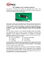
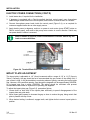
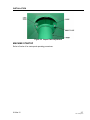
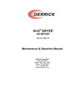
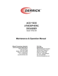
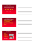
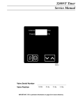
ACD-1500 ATMOSPHERIC DEGASSER Issued 15 Nov 09 Rev 15 Mar 12 Maintenance & Operation Manual DISCLAIMER Derrick Corporation has taken care to ensure that all of its maintenance and operation manuals are accurate. However, we offer no guarantees or warranties in this regard. Our manuals are provided only as a guide to assist with the maintenance and operation. Derrick Corporation takes no responsibility for any losses, damage, or injuries that may occur as a result of using any of our manuals. It is ultimately the operator’s responsibility to ensure that the operation, repair, and maintenance of equipment complies with all applicable national and local regulations, including safety regulations. THIS MANUAL IS PROVIDED BY DERRICK CORPORATION ON AN “AS IS” BASIS AND DERRICK CORPORATION EXPRESSLY DISCLAIMS ANY AND ALL WARRANTIES, EXPRESS OR IMPLIED, INCLUDING WITHOUT LIMITATION WARRANTIES OF MERCHANTABILITY AND FITNESS FOR A PARTICULAR PURPOSE. IN NO EVENT SHALL DERRICK CORPORATION BE LIABLE FOR ANY DIRECT, INDIRECT, INCIDENTAL, PUNITIVE, OR CONSEQUENTIAL DAMAGES OF ANY KIND WHATSOEVER WITH RESPECT TO THE MANUAL AND EQUIPMENT. Mineral Processing, Industrial, & Environmental Applications Derrick Corporation 590 Duke Road Buffalo, New York 14225 Phone: 716.683.9010 Fax: 716.683.4991 www.derrickcorp.com Oil & Gas Applications Derrick Equipment Company 15630 Export Plaza Drive Houston, Texas 77032 Phone: 281.590.3003 Toll Free: 1.866.DERRICK Fax: 281.442.6948 www.derrickequipment.com UNIT NUMBER IS KEY TO DERRICK SERVICE All inquiries to Derrick must include the equipment unit number. The stainless steel unit number tag attached to each piece of Derrick equipment is your key to efficient service and support. Typical Derrick Unit Number This unique number gives vital information to Service personnel who use it to identify the correct parts when filling orders, provide accurate responses to service questions, track documentation, and trace the equipment’s history or configuration. In short, the unit number provides the critical information needed to ensure that Derrick customers receive the best possible service. The unit number consists of a two-character alphabetic prefix that identifies the equipment type and a series of numeric characters that signify the sequence of the machine’s manufacture. For example, unit number MA000001 would be the first screening machine manufactured by Derrick. Alphabetic prefixes currently in use are: MA - Screening Machine AD - Desilter and Desander DG - Degasser AG - Mud Agitator CF - Centrifuge SF - Screen Frame To ensure that it will remain intact over many years of rigorous service, the heavy-gage tag is riveted to a structural member such as the shaker support structure. It is not to be confused with any other identifier on the machine such as a vibrator motor serial number. For convenient availability, the unit number is also recorded in the Operation and Maintenance manual shipped with the equipment. When contacting Derrick for any equipment question or need, always have the unit number in your possession. It’s the best way to get the most efficient service from our dedicated Service and Engineering personnel. ABOUT THIS MANUAL In this electronic manual, all sections and paragraphs listed in the CONTENTS are linked to the corresponding text. Navigate the electronic manual as follows: 1. To view any desired information, display the CONTENTS page and move the cursor to the desired paragraph or section title. 2. To display the desired information, click on the listing when the pointing finger appears over the text. 3. When finished viewing the text, press Alt + left arrow key to return to the CONTENTS page. 4. If desired to return to the same information, press Alt + right arrow. To locate a different item, repeat steps 1 and 2. 5. Blank pages are included to facilitate accurate two-sided printing on a standard copier. To print any individual section, simply enter the PDF page number range at the top of the screen (not the page number at the bottom of each page). This document contains proprietary information of Derrick Corporation. It is intended solely for the information and use of parties operating and maintaining the equipment described herein. Such proprietary information may not be used, reproduced, or disclosed to any other parties for any other purpose without the expressed written permission of Derrick Corporation. Continuous improvement is a policy of Derrick Corporation. All instructions and procedures are subject to change without notice. CONTENTS Section Page 1 - Introduction ............................................................................................. 1-1 Date 15 Apr 11 Overview ................................................................................................. 1-1 Safety ...................................................................................................... 1-2 Equipment Use ........................................................................................ 1-2 Description and Operation ....................................................................... 1-2 Major Components .................................................................................. 1-4 Product Support....................................................................................... 1-6 2 - Safety ....................................................................................................... 2-1 15 Apr 11 Introduction.............................................................................................. 2-1 Warnings ................................................................................................. 2-1 Material Safety Data Sheets (MSDSs) ..................................................... 2-2 3 - Installation ............................................................................................... 3-1 01 Mar 12 General ................................................................................................... 3-1 Safety ...................................................................................................... 3-1 Installation Sequence .............................................................................. 3-1 Storage .................................................................................................... 3-2 Site Preparation and Clearance Requirements ........................................ 3-2 Moving/Positioning the Equipment ........................................................... 3-2 Vent Line and Discharge Duct ................................................................. 3-5 Electric Power Connections ..................................................................... 3-5 Impact Plate Adjustment .......................................................................... 3-6 Machine Startup ...................................................................................... 3-7 4 - Operating Instructions ............................................................................ 4-1 15 Apr 11 General ................................................................................................... 4-1 Operating Safety...................................................................................... 4-1 Initial Startup ........................................................................................... 4-1 Normal Startup and Operation ................................................................. 4-1 Normal Shutdown .................................................................................... 4-2 Emergency Shutdown.............................................................................. 4-2 15 Mar 12 TOC-1 ACD-1500Degasser CONTENTS Section Page 5 - Maintenance............................................................................................. 5-1 Date 15 Apr 11 General .................................................................................................... 5-1 Bearing Lubrication .................................................................................. 5-1 Troubleshooting ....................................................................................... 5-2 Parts Replacement .................................................................................. 5-3 Spare Parts .............................................................................................. 5-3 6-7 - Not Used 8 - Reference Drawings ................................................................................ 8-1 15 Mar 12 9 - Installation and Maintenance Log .......................................................... 9-1 15 Apr 11 TOC-2 ACD-1500Degasser 15 Mar 12 SECTION 1 - INTRODUCTION OVERVIEW This manual provides installation, operation, and maintenance instructions for the Derrick Atmospheric Centrifugal Degasser (ACD) 1500 (Figure 1-1). The manual is divided into several sections to assist the user in readily accessing the information. Personnel responsible for transporting, installing, operating, adjusting, or maintaining this equipment should be required to read and understand the information and instructions in this manual. One copy of this manual should be available and accessible at the equipment location. For maximum safety and performance, no additions and/or changes may be made to the equipment without the explicit written permission of Derrick Corporation. Genuine Derrick repair/replacement parts are required. Figure 1-1 ACD-1500 Atmospheric Centrifugal Degasser 15 Apr 11 1-1 ACD-1500Degasser INTRODUCTION SAFETY Section 2 of this manual contains relevant safety information relating to both operation and maintenance of this equipment. Be sure this information is read and understood by all personnel. DO NOT operate the equipment if defective or faulty mechanical or electrical components are detected. EQUIPMENT USE The degasser and associated components are designed exclusively for releasing entrained gases from slurries. Derrick Corporation does not authorize any other use of this equipment. Intended usage of equipment includes compliance with the operating, maintenance, and safety procedures included in this manual. DESCRIPTION AND OPERATION The ACD-1500 degasser (Figure 1-2) is designed to be immersed in a mud tank. The degasser uses impact/turbulence combined with a large surface area of exposure to liberate gas from the mud. Entrained gases are removed from drilling fluid by exposing a thin film of the mud to the atmosphere. Drilling fluid is pumped by the centrifugal pump at the bottom of the degasser up through the pump riser and delivered to the impact plate, which disperses the liquid horizontally against the interior surface of the spray tank. The mud spreads evenly across the horizontal surface of the spray tank, allowing the bubbles to break free from the mud. Degassed mud flows out the discharge outlet and returns to the tank. Mud is continuously circulated from the tank through the degasser and back to the tank. This recirculation process maximizes gas removal. For proper functioning, the fluid level in the mud tank should be higher than the centrifugal pump bolting flange. The liberated gas exits the vent flange at the top of the spray tank. The exhaust blower at the top of the vent assists in drawing gas away. The blower’s discharge flange may be connected to a pipe flange having an 8-1/2” (215mm) diameter circular 4-hole bolt pattern to transport the gas away from the degasser. The ACD-1500 degasser processes up to 1500 gallons per minute (gpm), depending on the impact plate gap. This adjustable gap may be varied within a range of 1/4” to 1-1/4” (6mm to 32mm) in 1/4” (6mm) increments to control the thickness of the dispersed film. By forcing the mud through the small gap between impact plate and pump riser, it strikes the walls of the spray tank with considerable force, producing turbulence that assists in liberating gas from the mud. Maximum process throughput is achieved with the largest impact plate gap, while flow is diminished with a smaller gap. Generally, the higher the flow the lower the release of entrained gas. The impact plate gap is adjusted to meet the mud conditions. High gas content may warrant a small gap to maximize removal of entrained gas, while a larger gap may be suitable when gas content is lower and higher flow is desired. 1-2 ACD-1500Degasser 15 Apr 11 INTRODUCTION Figure 1-2 ACD-1500 Degasser Functional Diagram 15 Apr 11 1-3 ACD-1500Degasser INTRODUCTION MAJOR COMPONENTS The degasser (Figure 1-3) consists of a spray tank, electric motor-driven centrifugal pump, impact plate, electrical control panel (optional), vent, and exhaust blower. These components are described in the following paragraphs. Spray Tank Fluid dispersed at high velocity by the impact plate spreads across the interior surfaces of the spray tank. The tank’s shape encourages release of entrained gas from the mud. Centrifugal Pump Fluid is drawn into the degasser from the bottom of the mud tank by the centrifugal pump. The pump is driven by the main electric motor at the top of the degasser through a gear unit that transmits the motor’s rotation to a shaft extending downward to the pump. The shaft is supported by two bearings that control the shaft movement in both axial and radial directions. Clamping collars installed on the shaft ensure that minimal thrust is applied to the vertical shaft. Impact Plate Fluid pumped upward through the riser by the centrifugal pump strikes the circular impact plate, which disperses the fluid horizontally into the spray tank. Its slotted mounting holes permit vertical positioning of the impact plate to vary the gap between the top of the riser and the plate. Serrated tabs ensure positive setting of the gap at six locations. After properly positioning the impact plate, tightening the attaching hardware secures the plate to a fitting at the top of the spray tank. Electrical Control Panel (Optional) If equipped with an electrical control panel, three-phase AC electric power is connected inside the control panel to supply power to the main motor and exhaust fan motor. If equipment is supplied without the control panel, electrical connections are terminated at the main motor and fan motor. A customer-supplied starter box must then be connected to the motors to supply power. In addition to the START and STOP switches used to turn the machine on and off, the optional control panel contains a power contactor, provisions for connecting external controls and indicators, and other electrical components. Both motors are protected by thermal overloads to shut down the power in case of excessive current draw. Vent Aided by the exhaust fan, liberated gas flows upward through the vent and exits the flange at the top of the vent. A backdraft damper on the outside of the vent pipe permits entry of ambient air to mix with the gas and facilitate gas extraction. Opening of the damper is facilitated by the exhaust fan. Exhaust Blower The exhaust blower aids in removing potentially hazardous gases from the degasser. The outlet flange should be connected to a suitable pipe to convey the liberated gases to a safe location. 1-4 ACD-1500Degasser 15 Apr 11 INTRODUCTION Figure 1-3 ACD-1500 Degasser Major Components 15 Apr 11 1-5 ACD-1500Degasser INTRODUCTION PRODUCT SUPPORT Derrick offers 24-hour-per-day, 7-day-per-week product support. Product support includes screen replacement / ordering information and repair / replacement parts and service for the entire product line. Refer to the following table for the parts / service center nearest you. PARTS SALES & SERVICE LOCATIONS Colorado Grand Junction - 970.241.2417 Louisiana Broussard - 877.635.3354 New York - Corporate Headquarters Buffalo - 716.683.9010 Oklahoma Oklahoma City - 405.208.4070 Texas Houston (Oilfield Headquarters) - 866.DERRICK (337.7425) 281.590.3003 North Texas (Bridgeport) - 405.208.4070 South Texas (Corpus Christi) - 361.299.6080 West Texas (Midland) - 405.397.4089 East Texas, Arkansas, and Louisiana - 281.546.1166 Wyoming Casper - 307.265.0445 North Dakota Williston - 701.572.0722 CONTACT INFORMATION Location Derrick Corporation 590 Duke Road Buffalo, New York 14225 USA 1-6 ACD-1500Degasser Telephone Facsimile (FAX) 716.683.9010 716.683.4991 E-Mail / Website General Service Manager [email protected] 15 Apr 11 SECTION 2 - SAFETY INTRODUCTION This section contains a summary of WARNINGS used in this manual and a list of material safety data sheets (MSDSs) applicable to the equipment. The ACD-1500 Degasser has been designed to perform the stated functions safely. WARNINGS All persons responsible for operation and maintenance of this equipment must read and understand all safety information in this manual prior to operating and/or maintaining the equipment. The safety warnings listed below are included in applicable procedures throughout this manual. Sound WARNING! TO PROTECT AGAINST HEARING LOSS, HEARING PROTECTION SHOULD BE WORN AT ALL TIMES WHEN WORKING ON OR NEAR DERRICK MACHINES. Electrical Hazards WARNING! TO AVOID SERIOUS PERSONAL INJURY BE SURE EQUIPMENT IS LOCKED OUT, TAGGED OUT, AND DE-ENERGIZED PRIOR TO PERFORMING MAINTENANCE AND/OR ADJUSTMENTS. WARNING! MOTOR MUST BE OPERATED AT THE DESIGNATED SUPPLY VOLTAGE. WARNING! HIGH VOLTAGE MAY BE PRESENT. BE SURE FUSED DISCONNECT SUPPLYING ELECTRICAL POWER TO THIS EQUIPMENT IS OPEN. LOCK-OUT AND TAG-OUT POWER SUPPLY TO PREVENT ACCIDENTAL APPLICATION OF POWER WHILE MAINTENANCE AND/OR ADJUSTMENTS ARE IN PROGRESS. WARNING! ELECTRICAL CONNECTIONS MUST BE MADE IN ACCORDANCE WITH THE NATIONAL ELECTRICAL CODE (NEC) AND ALL APPLICABLE LOCAL CODES. FAILURE TO COMPLY MAY RESULT IN AN UNSAFE CONDITION THAT COULD INJURE PERSONNEL OR DAMAGE EQUIPMENT. ENSURE THAT ALL ELECTRICAL AND CONDUIT CONNECTIONS ARE SECURE. 15 Apr 11 2-1 ACD-1500Degasser SAFETY Equipment Handling WARNING! TO ENSURE PROPER BALANCE AND ORIENTATION WHEN UNIT IS RAISED AND PREVENT DAMAGE TO COMPONENTS, ATTACH LIFTING SLINGS ONLY TO LABELLED LIFTING POINTS. DO NOT ATTEMPT LIFTING BY ATTACHMENT TO ANY OTHER LOCATION. WARNING! BE SURE THAT HANDLING DEVICES HAVE SUFFICIENT LIFTING CAPACITY TO SAFELY HANDLE THE WEIGHT OF THE EQUIPMENT. Operation WARNING! ALL OPERATING AND MAINTENANCE PERSONNEL MUST READ AND UNDERSTAND ALL SAFETY INFORMATION IN THIS MANUAL BEFORE WORKING WITH THE EQUIPMENT. Maintenance WARNING! HIGH VOLTAGE MAY BE PRESENT. ALWAYS OPEN FUSED DISCONNECT SUPPLYING ELECTRIC POWER TO THE EQUIPMENT, AND LOCK OUT AND TAG OUT POWER SUPPLY BEFORE PERFORMING ANY MAINTENANCE OF EQUIPMENT. MATERIAL SAFETY DATA SHEETS (MSDSs) Material Safety Data Sheets (MSDSs) advise personnel of the properties and any possible hazards associated with these materials. Emergency first aid procedures, special precautions, emergency telephone number, and other relevant data are contained in the MSDSs. These documents are prepared by the product manufacturers, which have sole responsibility for accuracy of the information. The MSDSs listed below apply to products used in the manufacture of the Derrick equipment. Where shown, dates are current as of the publication date of this manual. The latest MSDSs may be obtained from the product manufacturer. MATERIAL DESCRIPTION – WHERE USED MSDS No. / Date Paints PPG Dimetcote 302H Green 302F0250 Resin - Top Coat 1302H-5A / 04-11-10 PPG Dimetcote 302H Clear 302G0910 Cure - Top Coat 1302H-B / 01-21-10 PPG PSX 700 Neutral Tint Resin - Undercoat PX700T3 / 02-28-08 PPG PSX 700FD Cure - Undercoat PX700FD-B / 01-11-07 Sealant Loctite Anti-Seize Lubricant - Fasteners 2-2 ACD-1500Degasser 76764 / 05-27-09 15 Apr 11 SECTION 3 - INSTALLATION GENERAL This section describes the recommended installation procedure for the ACD-1500 Degasser. Instructions include equipment handling, equipment leveling, and electrical connections. SAFETY Read and understand ALL safety information presented in this manual before installing and operating this equipment. Refer to Section 2 for a summary of Warnings affecting installation, operation, and maintenance of this equipment. Before beginning the installation, review the information presented in Equipment Hoisting later in this section. Pay particular attention to the information concerning lift points. Failure to observe proper equipment handling procedures may result in serious personal injury or death and/or damage to the equipment. WARNING! BE SURE THAT HANDLING DEVICES HAVE SUFFICIENT LIFTING CAPACITY TO SAFELY HANDLE THE WEIGHT OF THE EQUIPMENT. WARNING! TO ENSURE PROPER BALANCE AND ORIENTATION WHEN UNIT IS RAISED AND PREVENT DAMAGE TO COMPONENTS, ATTACH LIFTING SLINGS ONLY TO LABELLED LIFTING POINTS. DO NOT ATTEMPT LIFTING BY ATTACHMENT TO ANY OTHER LOCATION. INSTALLATION SEQUENCE Following is the sequence of steps for installing the ACD-1500 Degasser. The sequence may vary depending on the user’s facilities and previous experience with this type of equipment. 1. Read and understand all safety information in Section 2 before installing and operating this equipment. 2. Install the degasser in the drilling fluid tank downstream of the shale shaker. 3. Be sure the unit is secure and level on the tank. 4. Connect a duct to discharge outlet, if required. 5. Connect a vent line to the exhaust fan flange to carry gas to a safe area. 6. Install starter box if necessary, and connect electrical power supply to the equipment. 7. Refer to Section 4 for startup and operating instructions. 01 Mar 12 3-1 ACD-1500Degasser INSTALLATION STORAGE Storage Before Use If equipment is not being installed immediately, it should be stored in a dry environment (50 percent relative humidity or less). A dry environment will ensure that the machine remains in the same condition as when it was received. If unit is stored outdoors, use a UV-resistant tarp, or UV-resistant shrink wrap. Install vents when using shrink wrap. Seal the Operation and Maintenance manual in plastic and attach to unit. Storage After Use WARNING! BEFORE PREPARING THE DEGASSER FOR STORAGE, SHUT DOWN, DISCONNECT, AND LOCK OUT AND TAG OUT ELECTRIC POWER. Prior to an idle period of any duration the unit must be thoroughly cleaned inside and out to prevent damage from hardening of built-up mud. After cleaning the unit, cover outlet flange. Preventive Maintenance During Storage To prevent motor damage during the storage period, perform the following precautionary activities: 1. Check insulation resistance of the motor windings using a megohmmeter (Megger). Periodically measure and record the readings in a log. Investigate any significant drop in resistance immediately. 2. Rotate the motor shaft 10 full turns at least once every two months to decrease the likelihood of bearing deterioration during storage. Note! Do not lubricate bearings during storage. Motor bearings are packed with grease at the factory and can be damaged by excessive grease. SITE PREPARATION AND CLEARANCE REQUIREMENTS Prior to installation of equipment, verify that electricity is available at the installation site. Also ensure that clearances around the equipment are adequate. Prepare the installation site as follows: 1. Check that discharge chute, if used, is properly sized for the equipment (refer to general assembly drawing in Section 8 for discharge size. 2. Verify that available electric power supply at the site agrees with electric power requirements of the equipment. MOVING/POSITIONING THE EQUIPMENT The degasser is shipped fully assembled. A label indicating the weight of the unit is affixed to the equipment. While the machine is still mounted on the wooden shipping skid, the unit should be transported on the ground using a forklift. After the machine is removed from the shipping skid, either a forklift or overhead-lifting device may be used. 3-2 ACD-1500Degasser 01 Mar 12 INSTALLATION WARNING! BE SURE THAT HANDLING DEVICES HAVE SUFFICIENT LIFTING CAPACITY TO SAFELY HANDLE THE WEIGHT OF THE EQUIPMENT. WARNING! WHEN USING AN OVERHEAD LIFTING DEVICE, USE ONLY THE LIFTING LUGS PROVIDED. DO NOT ATTEMPT TO LIFT MACHINE USING ANY OTHER LIFTING LOCATION. Equipment Hoisting Two lifting lugs are attached to the degasser to allow attachment of an overhead lifting device (Figure 3-1). The lugs are labeled “LIFT HERE ONLY”. DO NOT attempt to lift the degasser by any other non-designated portion of the unit. Install a clevis that is capable of supporting the equipment weight through each lifting lug, and attach the hoisting sling to the clevises. Figure 3-1 ACD-1500 Degasser Lifting Arrangement 01 Mar 12 3-3 ACD-1500Degasser INSTALLATION Positioning and Mounting Position the degasser with sufficient space around unit to allow access to various components by operators and maintenance personnel. Approximately 2’ to 3’ (610mm to 914mm) space is required on all four sides of the equipment. The recommended installation is to weld rails close to the degasser to “trap” the machine in place. The degasser should not be welded to the tank as this installation will prevent access to the pump. Typical operation and maintenance functions include the following activities: • Removing the access panels • Greasing drive shaft bearings • Connection of exhaust line • Access to electrical control panel Leveling For proper operation, the degasser must be properly leveled along its length and width (Figure 32). A 4’ (1219mm) level is recommended. Shim the equipment as required to level the unit. Figure 3-2 Degasser Leveling 3-4 ACD-1500Degasser 01 Mar 12 INSTALLATION VENT LINE AND DISCHARGE DUCT Vent Line 1. Connect a 4-1/2” (114mm) ID vent line to the exhaust fan outlet. The vent line flange must have a four-bolt 8-1/2” (38mm) diameter pattern. The vent line must be long enough to convey the discharged gas to a safe area. 2. The vent line should be supported independently. Any elbows should be located at least two fan wheel diameters from the exhaust fan. Discharge Duct If degassed mud is to be conveyed away from the degasser, connect a 15” x 22-1/2” (381mm x 572mm) duct to spray tank outlet. The duct should slope downward to the receiving tank to facilitate flow away from the degasser. ELECTRIC POWER CONNECTIONS WARNING! TO AVOID SERIOUS PERSONAL INJURY BE SURE POWER TO EQUIPMENT IS LOCKED OUT, TAGGED OUT, AND DE-ENERGIZED BEFORE BEGINNING ELECTRICAL INSTALLATION. WARNING! MOTOR MUST BE OPERATED AT THE DESIGNATED SUPPLY VOLTAGE AND FREQUENCY. WARNING! A FUSED-DISCONNECT PRIMARY POWER SUPPLY WITH SUFFICIENT INTERRUPTING CAPACITY TO CLEAR THE MAXIMUM FAULT CURRENT CAPABILITY OF THE SYSTEM IS REQUIRED. WARNING! ELECTRICAL CONNECTIONS MUST BE MADE IN ACCORDANCE WITH ALL APPLICABLE NATIONAL AND LOCAL CODES. FAILURE TO COMPLY MAY RESULT IN AN UNSAFE CONDITION THAT COULD INJURE PERSONNEL OR DAMAGE EQUIPMENT. ENSURE THAT ALL ELECTRICAL AND CONDUIT CONNECTIONS ARE SECURE. The electrical connections should be performed only by trained, qualified personnel familiar with high-voltage applications and knowledgeable of all applicable state or local codes for installation of industrial equipment. A fused disconnect is required for primary power supply. The fused disconnect and wiring to the equipment shall be suitably sized and in accordance with all applicable national and local codes. The degasser is factory-wired to operate on three-phase power at the power configuration specified by the customer. If the degasser is not equipped with a Derrick-supplied electrical control panel, electrical connections are terminated at the main drive motor and exhaust fan motor. The customer must then bring power to the motors either from a starter box or other supply source. If degasser is equipped with a Derrick-supplied electrical control panel, the incoming supply connections are shown on the wiring schematic in Section 8. Following are general electric power connection requirements: 1. Install a fused disconnect device having sufficient interrupting capacity to clear the maximum fault current capability of the power supply system. 01 Mar 12 3-5 ACD-1500Degasser INSTALLATION ELECTRIC POWER CONNECTIONS (CONT’D) 2. Install starter box, if required for the installation. 3. If degasser is equipped with a Derrick-supplied electrical control panel, pass three-phase cable through conduit and into the control panel, and connect to terminal block or contactor. 4. Connect three-phase power leads inside the control panel (Figure 3-4), or as required for customer-supplied starter box or other supply source. 5. Apply electric power to degasser, and turn on power to main motor (press START button on Derrick control panel), and confirm that pump motor rotates in correct direction. Switch any two power leads if rotation is reversed. Note! If rotation is opposite, motor connections are reversed. Switch any two leads to reverse direction. Figure 3-4 Terminal Block Electrical Connections - Derrick Control Panel IMPACT PLATE ADJUSTMENT The impact plate is adjustable in 1/4” (6mm) increments within a range of 1/4” to 1-1/2” (6mm to 32mm). Generally, the gap should be set to accommodate the gas content of the drilling fluid. If gas content is high, it may be desirable to maximize release of gas by narrowing the impact plate gap. However, at the smallest opening, flow through the degasser will be approximately 500GPM; at its largest gap, flow is about 1500GPM. The setting should be consistent with process considerations and based on experience in operating the degasser. To adjust the impact plate gap (Figure 3-5), proceed as follows: 1. Loosen bolts on both ends of the impact plate sufficiently to permit disengagement of the impact plate and guide teeth. 2. Move impact plate upward to increase the gap or down to reduce the gap, being certain that plate is parallel with top of riser. 3. When desired setting is achieved, engage teeth, and tighten bolts to secure impact plate in position. 3-6 ACD-1500Degasser 01 Mar 12 INSTALLATION Figure 3-5 Impact Plate Adjustment MACHINE STARTUP Refer to Section 4 for startup and operating procedures. 01 Mar 12 3-7 ACD-1500Degasser SECTION 4 - OPERATING INSTRUCTIONS GENERAL This section includes initial and normal startup shutdown procedures for the ACD-1500 Degasser, as well as emergency shutdown. OPERATING SAFETY WARNING! ALL OPERATING AND MAINTENANCE PERSONNEL MUST READ AND UNDERSTAND ALL SAFETY INFORMATION IN THIS MANUAL BEFORE WORKING WITH THE EQUIPMENT. INITIAL STARTUP The initial startup procedure should be used when the equipment is being started for the first time, or when equipment has been returned to use after an extended period out of service. 1. Verify that all operators and maintenance personnel have read and understand all operating and safety information in Section 2. 2. Confirm that equipment has been installed in accordance with Section 3. 3. Check that correct electric power configuration is available in accordance with Section 3. 4. Be sure that all operators and maintenance personnel are clear of equipment before applying electric power to vacuum pump and centrifugal pump. 5. Closed fused disconnect to apply electric power to the machine, and turn on the centrifugal pump motor and exhaust fan motor. Liquid will then be drawn into the pump and circulated up to the spray tank. Check that centrifugal pump turns in proper direction to draw in liquid; if direction is opposite, reverse two electrical leads. Note! If rotation is opposite, connections are reversed. Switch any two power leads to reverse motor direction. NORMAL STARTUP AND OPERATION The following procedure shall be performed at each machine startup: 1. Be sure that all operators and maintenance personnel are clear of the equipment before applying electric power to centrifugal pump and exhaust fan motors. 2. Apply electric power to degasser. 3. Turn on exhaust fan motor, and turn on the centrifugal pump motor to begin circulating mud through the degasser. 15 Apr 11 4-1 ACD-1500Degasser OPERATING INSTRUCTIONS NORMAL SHUTDOWN The normal shutdown procedure is to be used for controlled stopping of operation. Normal shutdown is performed for routine activities such as cleaning, lubrication, inspection, or other routine procedure. 1. Shut down electric power to stop the centrifugal pump and exhaust fan. 2. Open fused disconnect that supplies electric power to the machine. EMERGENCY SHUTDOWN To immediately stop the machine in case of emergency, open the fused disconnect supplying electric power to the machine. 4-2 ACD-1500Degasser 15 Apr 11 SECTION 5 - MAINTENANCE GENERAL Proper maintenance will ensure maximum life and trouble-free operation. While the maintenance schedule presented in this section is not rigid, modifications should be based on experience with operating the equipment at your facilities. A maintenance log should be kept to help establish a routine maintenance schedule, as well as to monitor and adjust the schedule as necessary throughout the equipment’s life. When establishing a maintenance schedule consider duty cycle, ambient temperature, and operating environment. BEARING LUBRICATION WARNING! TO AVOID SERIOUS PERSONAL INJURY BE SURE EQUIPMENT IS LOCKED OUT, TAGGED OUT, AND DE-ENERGIZED PRIOR TO PERFORMING MAINTENANCE. The upper and lower shaft bearings (Figure 5-1) must be re-lubricated periodically based on hours of operation. For safety, lubrication is to be performed with the degasser shut down, locked out, and tagged out. Figure 5-1 Upper and Lower Shaft Bearing Grease Fittings 15 Apr 11 5-1 ACD-1500Degasser MAINTENANCE BEARING LUBRICATION (CONT’D) The recommended lubricant for the shaft bearings is NLGI grade 2 mineral oil lithium or lithium complex base grease. Grease should be injected into grease fitting until purged through the fitting regardless of the quantity added. Bearings should be re-lubricated in accordance with the following schedule: Daily Operating Hours Interval (Weeks) 8 10 16 5 24 3 TROUBLESHOOTING Fault diagnosis is As long as the mud level in the tank remains at or above the pump bolting flange, the degasser will circulate fluid up to the spray tank. Malfunctions are generally caused by incoming power disruptions or tripping of overloads or blown fuse(s) in the electrical power source. Always check these items and for correct incoming power first before proceeding with further checking and tests. If degasser is equipped with a Derrick-supplied electrical control panel, an electrical schematic diagram is included in Section 8 for assistance in tracing electrical malfunctions. If equipment is operated by a customer-supplied starter box or other power source, consult the corresponding electrical diagram for assistance in fault analysis. Before performing electrical continuity checks, always shut down, lock out, and tag out electric power to degasser. WARNING! TO AVOID SERIOUS PERSONAL INJURY BE SURE EQUIPMENT IS LOCKED OUT, TAGGED OUT, AND DE-ENERGIZED PRIOR TO PERFORMING MAINTENANCE. ACD-1500 DEGASSER TROUBLESHOOTING Trouble Degasser fails to start Degasser not operating properly. 5-2 ACD-1500Degasser Possible Cause Remedy No power or incorrect supply voltage Check that power is available at equipment, and verify that correct power is supplied to degasser. Incorrect electrical connections Check and correct any wiring defects. Improper installation Refer to Section 3. Incorrect startup procedure Shut down unit and restart per Section 4. 15 Apr 11 MAINTENANCE ACD-1500 DEGASSER TROUBLESHOOTING Trouble Low flow rate through degasser Excessive noise and/or vibration Possible Cause Remedy Impact plate not adjusted correctly Increase clearance between impact plate and riser. Low fluid level Check that fluid level in tank is above pump bolting flange. Raise level if necessary. Worn pump Inspect centrifugal pump for wear. Repair or replace pump as needed. Inlet opening partially blocked Turn off unit. Thoroughly clean inlet to remove large debris. If necessary, remove sediment from tank bottom. Pump shaft bearings worn Re-grease bearings in accordance with or require re-greasing Bearing Lubrication in this section. Replace bearings if still loose after regreasing. Low air flow from exhaust fan Excessive blower vibration Exhaust fan rotating in reverse Shut down electric power, and reverse any two leads. Improperly designed vent line Check and correct as necessary. Obstructed exhaust Remove any obstruction to air flow. Loose mounting bolts or other blower hardware Check and correct as necessary. Accumulation of debris on blower wheel Clean exhaust blower wheel. Worn bearings Replace blower motor. PARTS REPLACEMENT Defective parts should be replaced as soon as possible to prevent further damage to the equipment. Refer to the applicable drawings in Section 8 for Derrick component locations and part numbers. 15 Apr 11 5-3 ACD-1500Degasser MAINTENANCE SPARE PARTS The following table lists the recommended spare parts to support one ACD-1500 degasser for two years. However, since all potential part replacements cannot be predicted, the complete spare parts inventory should be based on the user’s experience with similar equipment. When establishing a spare parts inventory, consider the equipment’s duty cycle and operating environment. RECOMMENDED SPARE PARTS - ACD-1500 DEGASSER Part No. Description Consumable 2-Yr Qty G0008899 Primary Fuse No 2 G0008922 Secondary Fuse No 2 17183-01 Impact Plate No 1 G0009926 Blower Motor No 1 G0009171 Bearing, Radial and Thrust Load No 1 G0009070 Bearing, Radial No 1 17177-01 Shaft Stabilizer No 1 5-4 ACD-1500Degasser 15 Apr 11 SECTION 8 - REFERENCE DRAWINGS This section contains Derrick engineering drawings for your equipment. These drawings are included to provide assistance in troubleshooting, repair, and parts ordering. Number Title 17171-00 ACD-1500 Degasser General Arrangement 17173-00 ACD-1500 Degasser Parts List 17197-00 ACD-1500 Degasser Electrical Control Panel 17198-00 ACD-1500 Degasser Wiring Schematic 17199-00 ACD-1500 Degasser Electrical Component List 15 Mar 12 8-1 ACD-1500Degasser SECTION 9 - INSTALLATION AND MAINTENANCE LOG PURPOSE This section should be used by operating and maintenance personnel to record historical information gathered during the installation and operation of the Derrick equipment. If properly kept, the log will be useful for altering maintenance intervals and intercepting trends that may indicate the need for changing operating procedures. Each entry in the log should be dated for future reference and tracking. If required, additional pages may be added to the log by copying a blank page or simply inserting ruled paper at the rear of the section. Installation and Maintenance Notes: 15 Apr 11 9-1 ACD-1500Degasser INSTALLATION & MAINTENANCE LOG 9-2 ACD-1500Degasser 15 Apr 11 INSTALLATION AND MAINTENANCE LOG 15 Apr 11 9-3 ACD-1500Degasser INSTALLATION & MAINTENANCE LOG 9-4 ACD-1500Degasser 15 Apr 11 INSTALLATION AND MAINTENANCE LOG 15 Apr 11 9-5 ACD-1500Degasser INSTALLATION & MAINTENANCE LOG 9-6 ACD-1500Degasser 15 Apr 11 Document No.: PE-S-071-03-03 ® CERTIFICATE OF ORIGIN Equipment: Degassers Model: Vacu-Flo™ 1200, ACD-1500 Characteristics: 0-600VAC, 50/60Hz, 3PH Derrick Corporation acknowledges that the above set-forth product is manufactured in the United State of America as of the date of this certificate. This certificate is governed by the applicable purchase order terms in effect at the time of Derrick Corporation’s original shipment of the referenced product. Date: 29-December-2011 http://dmc-sps/qc/Certificates/Origin Standard/PE-S-071-03-03.doc Revison Number 2 Revision Date: 29-December-2011 Signature: Jennifer J. Polanowski Derrick Corporation Document No.: PE-S-011-08-00 ® CERTIFICATE OF QUALITY Equipment: Degassers Model: Vacu-Flo™ 1200, ACD-1500 Characteristics: 0-600VAC, 50/60Hz, 3PH Derrick Corporation acknowledges that the above set-forth product conformed to the requirements for the applicable purchase order at the time of its original shipment by Derrick Corporation in that all construction materials and components were new and unused, were manufactured for this product, and that it was free of any known defects as to their design, material and workmanship. This certificate is governed by the applicable purchase order terms in effect at the time of Derrick Corporation’s original shipment of the referenced product. Date: 29-December-2011 http://dmc-sps/qc/Certificates/Quality/PE-S-011-08-00.doc Revison Number 2 Revision Date: 29-December-2011 Signature: Jennifer J. Polanowski Derrick Corporation Document No.: PE-S-070-04-00 ® SHIPPING FINAL INSPECTION AND RUN TEST CERTIFICATE Equipment: Degassers Model: Vacu-Flo™ 1200, ACD-1500 Characteristics: 0-600VAC, 50/60Hz, 3PH The product listed above was inspected and found to be in conformance with Derrick Corporation’s internal coating, run test, and assembly inspection documents that were required for the type of equipment manufactured in accordance with the Derrick quality system. This certificate is governed by the applicable purchase order terms in effect at the time of Derrick Corporation’s original shipment of the referenced product. Date: 29-December-2011 Signature: Jennifer J. Polanowski Derrick Corporation http://dmc-sps/qc/Certificates/Shipping Final Inspection and Run Test/PE-S-070-04-00.doc Revison Number 2 Revision Date: 29-December-2011