1
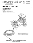
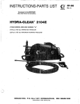
This manual contains IMPQRTAfflT
WARNINGS and INOTRUCTIQMS
READ AND RETAIN FOR REFERENCE
Pressure Washer
P/N 800-066 SERIES A
3200psi7220 bar) OPERATING PRESSURE
3400 psi (235bar) MAXIMUM WORKING PRESSURE
i
GRACQ [email protected]. %QX I
'
M
1MUNNIEAPOLDS, MN 5544GV444
OCOPYRIGHT 1984 GRACO INC.
iNJECT!ON HAZARD
FIRE
Fluids under high pressure from spray or leaks can
penetrate the skin andcauseextremelyserious
injury. including the need for amputation.
D O not spray flammable liquids. Do not operate the
engine where combustible fumes or:dust
may be
present.
NEVER point the spray gun at anyoneor any part of
the body.
GAS ENGINE ~
NEVER put hand or fingers over the spray tip.
NEVER fill fuel tank while engineis running or hot.
Avoid the possibility of spilled fuel causing a fire.
Always refuel slowly toavoid spillage.
NEVER try to stop or deflect leaks with your hand or
body.
~
E
I
,:NEVERoperate engine in a closed building unlessthe
ALWAYS have the tip guard in place when spraying.
MAED!CAL KREWKLWENK
If any fluid appears topenetrate
EMERGENCY MEDICAL CARE
DO NQT TREAT AS
AT ONCE.
A
SIMPLE CUT.
Tell the doctor exactly what fluid was injected. For
treatmentinstructionshave
your ductor call the
NATlONAL POISON CENTER NETWORK
exhaust is pipedoutside.
The exhaustcontains
carbon monoxide, a poisonous, odorless and invisible
gas, which, if breathed, may cause serious illnessor
possibly death.
NEVER make adjustments on machinery while it is
connected to the engine; first remove the ignition
cable from
the
spark plug.
Turning
over the
machinery by handduring adjusting or cleaning
might start theengineandmachinery,causing
serious injury to the operator.
(442)EBf-866$
NEVER run the engine with governor disconnected,
AVOID CO@PONENK RUPTURE
or operate at speeds in excess of 3600 RPM load.
Even after you shut off the gasoline engine, there is
high pressure in the pump, hose and gun until you
release it by triggering the gun. So before removing'
the spray tip or servicing the unit, always shut offthe
.
unit and trigger the gun to release pressure.
Precaution is thebest insurance against an
accident.
When starting the engine, maintain a safe distance
from moving parts of the equipment.
'
Be sure that .ail
accessory
itemsandsystem
components will withstand the pressure developed.
NEVER exceed the pressure ratingof any component
in system. NEVER alter or modify equipment -your
personal safety, as well as the functionofthe
equipment,.isat stake. Maximum working pressure
3400 PSI (235 bar).
GENERAL
NEVER run the unit with the belt guard
removed.
Keep clear of moving parts when the unit is running.
Before eachuse, check hosefor weak, wornor damaged
conditions caused by traffic, sharp corners, pinching or
kinking.Tighten all fluid connectionssecurelybefore
each use. Replace any damaged hose.
Observe
detergent
m.anufacturer's
safety
precautions. Avoid getting detergent or other liquids
in your eyes. Follow the directions on the container
regarding contact'
with
eyes.
nose,
and skin,
breathing fumes, etc. Always wear full goggles to
protect your eyes from the spray aswell as anydebris
dislodged by the spray. If necessary, wear gloves or
other protective clothing. If antidotes or treatment
are recommended,'be prepared to use them.
Do not usechemicals or agents
which are not compatible
with Buna-N and W C or neoprene cover of hose.
DON'T spray toxic chemicals such as insecticide or
weed killer.
Do"not leavea pressurized unit unattended. Shutoff the
unit and release Dressure before .leavina.
I
IMPORTANT
United States Government safety standards have been adopted under the Occupational Safety and Health
Act.
These standards - particularly theGeneral Standards, Part 1910, and the Construction Standards, Part 1926should be consulted in connection with your use of airless spray equipment,
2
801-644
~
FUEL LINE I
roN'oFFSW'TcH
r-CHOKE RING
Refer to the engine instructionbooklet provided with
the unit.
Connect To Water Supply
CAUTION
Install Hose and Spray Gun
Connect the spray hose to the
spray gun by inserting
the pin at theend
of the hose intothe
quick
disconnect coupler on the gun. Connect the hose to
the fluid outlet in the same way.
Cleaning Accessories
For spraying detergent or other cleaning solution, we
injector
kit.
See
recommend using a chemical
Accessoriesand instructionmanual 801-645for
installation and operation.
..
~.
."
. ..
..
For removingrustandoldpaintwerecommendusing
a water sandblaster. See Accessoriesand instruction
manual, 801 -646for installation and operation.
Before attaching to water supply, check local
plumbing code regarding cross-connection to
water supply.
Do not exceed 160°F (70°C)water temperature to
pump in a direct supply system.
Connect a hose with a t least a 314 in: (19 mm) ID
from your city water supply
to the unit's 3/4 in.
garden hose threaded inlet.The supply hose should
not be more than 50 f t . (15 m) long.
NOTE:
For a directsupply system. your water
source at the unitmust have a flow rate
of
A T LEAST 5 GPM (19 LITER/MIN).
If your operating conditionsare different fromabove.
contact our
Customer
Service
Department
for
assistance.
801-644
3
-
startup
Shutdown and Care Of Unit
When unit is not in use, turn ,off water supply.
Check the oil and gasoline levels.
When shutting down for the day or weekend, shut off
unit, shut off water supply valve, and trigger gun to
relearn pressure. Wipe off the unit with a damp rag.
Before starting, be sure to readthe
safety warnings and
setup instructions.
Turn on the watersupply.
I
c
Shut off cleaning unit when not actuallyspraying,
for longer pump life. The pump will overheat if left
running for over 10 minutes without spraying.
Trigger the gun.
Open the by-pass valve located on the pump.
Check the filter screen in thewater inlet connection as
often as necessary, at least daily.Do not operate theunit
with the inlet and filter screen removed,
Open vent onfuel iankcap. Connen fuel line from tank
to engine fuel coupling. Prime gas line by squeezing
bulb in line threeto five times. Advance throttle control
to the start position.
Turn ON/OFF switch (located under the engine air
cleaner) to the ON position. Grasp the starter cord
handle, put your foot on the frameor wheel to steady
the unit, pull the cord rapidly out two or three feet.
Repeat if necessary with the choke ring pulled out.
When engine fires and beginsto run, push choke ring
back in. Close by-pass valve on pump.
DO NOT try to adjust the unloader valve. Changing
the
setting
may cause^ excessive
'pressure,
intermittent unloader operation and increased wear
on parts and will void the warranty.
PUMP MUST NOT BE RUN DRY and must be drained of
water prior to exposure to freezing temperatures. Use
and Store the unit where it will not besubjected to
freezing temperatures. If water does freeze in the unit,
thaw before trying to start. A 50% anti-freeze solution
may be pumped prior to cold weather storage.
Use only spraytips that are matchedto the unit to avoid
excessive cycling and wear of the unloader valve. See
ACCESSORIES.
CAUTION
the pump will result. Always besurewatersupply
is comoletelv turned on before ooeratina.
~
~~
~
Inspect all connectionsfor
necessary.
~
~~~~
~~
~~
~~
any leaks. Tighten if
Cleaning
For Hydra-Clean technique, see the Chemical Injector
manual, 801-645.
For
abrasive
cleaning, see the WaterSandblaster
manual, 801 -646. '
Let a frozen pump thaw in a warm place. Don't
pour hot water on a frozenpump. A sudden
temperature
change
may
crack
the ceramic
plungers.
Do not pump caustic materials.
Before extended storage,flush the pump with light oil.
Avoid dragging hose over an abrasive surface such as
cement. This causes excessive wear and shorter hose
life.
Clean the intake line strainer daily.
1. Shut off the cleaning unit and triggerthe gun to
relieve pressure. Engage the trigger safety.
2. Keep the nozzle and thetubepointedawayfrom
you and everyone else.
Do not put your hand over the tip to push the
nozzle into place. Grasp it from the sideand
keep your fingers away from the tip.
3.
4. Do not let anyone else touch the spray valve
Lubrication and Care
Change the engine oil after
every 100 hoursof operation. Drain oil with engine warm. Engine requires 3
pints (1.4 liters) 30W oil. See separate instruction
manual for maintenance procedures.
Fill pump crankcase
to dot on oilgauge window with
34 02. (1 .Oliters) of crankcase oil (partno. 801 -144)
or equivalent SAE 40 weight hydraulic oil with antiwear and rust inhibitor additives. Change initial fill
after 50 hour running period. Change oil every 3
months or a t 500 hour intervals.
while you are cleaning nozzles.
5. Be sure the slip ring is pushed forward to lock
the nozzle in place before triggering the spray
stment or mo
Altering or adjusting unloader will not increase
performance of unir.
Service of the unloader must be performed onlyby
aualified service oersonnel.
4
801-644
.
. . ~ .
PROBLEM
CAUSE
"
En ine Will Not Start
O r a a r d To Start.
No gasoline in fuel tank or
carburetor.
Water in gasoline or old fuel.
Choked improperly. Flooded
engine.
the
out
Dirty carburetor air filter.
Spark plug dirty or improper
!gap.
Spray gun closed.
Fill the tank with gasoline, open fuel shut-off
valve.
Check fuel line and carburetor.
Drain fuel tank and carburetor. Use new fuel
and dry. suark
.
.ulug.Open choke and crank engine several times
to
clear
gas.
.
Remove and clean.
Clean, adjust the gap or replace.
I
"
Partially plugged air filter.
Spark'plug dirty, wrong gap,
I3r wrong type.
IIncorrect ignition tithing.
Engine Misses Or Lacks
Power
Remove and clean.
Clean, adjust the gap, or replace.
Time engine.
"
1JVorn
Low Pressure
nozzle.
IJelt slippage.
4ir leak in inlet plumbing.
I%lief valve stuck, partially
I,lugged or improperly
adjusted; valve seat worn.
Inlet suction strainer clogged01
Improper size.
\aorn packin Abrasives in
Ilumped f l u i j o r severe cavitat:ion. Inadequate water supply.
I=oulsd or dirty inlet
or discharge
\ralves.
\Norn inlet or discharge valves.
I.eaky discharge hose
Replace with nozzle of proper size.
Tighten or replace; usecorrect belts and replace
I
both a t same time.
Disassemble, reseal, and.reassemble.
Clean. and adjust relief valve; check for worr
and dirty valve seats. Kit available.
Clean. Use adequate size. Check more
frequently.
Install proper filter. Check flow available to
pump.
Clean inlet and discharge valve assemblies.
Replace worn valves, valve seats and/or
discharae hose.
"
'ump runs extremely rough, fiestricted inlet or air entering
xessure low.
t he inlet plumbing.
Inlet restrictions and/or air
I/eaks. Stuck inlet or discharge
umalve.
1.eaking H.P. seals.
Pro er size inlet plumbing; check for air tight
sea?
Clean out foreign material, replace worn valves.
Reolace seals.
"
Nater kaka e from under
he manifold!
~~
Nater in pump crankcase.
cVorn packing.
-
Install new packing.
nAay be caused by humid,air
C ondensing
C rankcase.
-
Change oil at 3 month or500 Hour intervalsusing
into water lnslde the
Crankcase Oil (other ap roved oil every month or
200 hours) P.N. 801-f44.
:requent orprematurefailure! C;cored plungers.
Replace plungers.
)f the packmg.
Ch e r pressure to inlet manifold. Reduce inlet pressure.
Replace plungers.
' Clamaged or worn plungers.
Prbrasive material in the fluid Install properfiltration on pump inletplumbing.
being pumped.
Check pressures and fluidinlet temperature; be
Eixcessive pressure and/or
jure they are within speclfted range.
tl?mperature of fluid being
Pumped.
3educe pressure.
Clver pressure of pumps.
R:unning pump dry.
lo not run pump without water.
-
;trong surging at the inlet
nd low pressure on the
ischarge side.
Foreign particles in the inlet or
d,ischarge valve, or worn inlet
a nd/or discharge valves.
:heck for smooth lap surfaces on inlet and
iischar e valve seats. Discharge valve seats and
nlet va ve seatsmay be lapped on a veryflne 011
;tone.
9
L
801-644
5
6
801-644
REF. PART
NO.
QTY
800-130
1
GUN ASSEMBLY,
see
pans
1
drawing/list page 9
1
TIP. 0005 MEG, 1/4 thd.
2 '801-640
1
3 '801-667
TIP,'1505
MEG. 1/4 thd.
PUMP ASSEMBLY,
pans
see
4 800-059
800-082
drawing/list
36
1page 11
drive BELT,
801-541 37
2
5 801-616
6 801-141
LABEL, warning
1
7 . ,801-129
LABEL warning
801-619
39
1
8 801-543
DECAL Graco/Vangard
1
9 801-131
no. serial
PLATE,
1
ENGINE
ASSEMBLY,
18see
h.p.,
10 800-084
parts drawing/lin page
1 7
11 801-546
SCREW, hex, 318-16 x 1-1/2"
4
SCREW,
hex,
5116-18x 1-1/2"
4
12 801088
801-302
13
SCREW,
hex,
5/16-18 x 1"
8
14 801-517
SCREbV. hex, 5/16-18 x 3"
1
15 801-589
SCREW,
hex,
3/8-16 x 7"
,1
16 801-559
SCREW,
hex.
M 8 x 30 M M
504
BUSHING, mach., 3/4
2
801-547
17
NIPPLE,
hex.
3/8 x 3/8 NPT
52.
1
18 801-603
WASHER,flat. 1/4
53 26
801-023
19
20 801-015
WASHER,
flat.
5/16
5
4
801-139
21
WASHER, lock. 1/4
22 801-025
WASHER, lock, 14
5/16
*801-568
23
QUICK
COUPLE,
male,
318
1
24 801.024
hex,
NUT,
5/16-18
9
-499801 25
locking,
NUT,
3/8-16
1
26 .801-020
locking,
NUT.
1/2-13
2
4
GROMMET
801-546
27
1
28
801-571
HOSE, H.P., 3/8 x 50 ft.
1
29 801-004
PULLEY,
pump
30 801-617
PULLEY,
engine
1
'1
801-376
31
HUB,
pulley
. .
'
REF. PART
NO.NO.
801-137
32
33' 800-083
34 '801-569
35 800-058
38
801-618
40 -609
801
41
-505
801
42
43
801-507
801-506
801-550
45 801-538
46 801-504
48 801-539
49 801-363
. 801-537,
51 +EO1-614
'801-615
801-130
54
801-132
55 801-608
56 801-605
57 801-607
58 801-606
59 801-369
80160
2 -61
61 801-576
62
801
-090
63 601-680
44
'
QlV
DESCRIPTION
KEY, pulley
GAS TANK ASSEMBLY, see
parts drawing/list page 8
QUICK
COUPLE,
male
STIFFNER
RAIL
WELDMENT
CHASSIS'WELDMENT
HANDLE
BELTGUARD
COVER
BELTGUARD BASE
BRACKET, suppon
SPRING
FOOT
RETAINER
BOOT,
leg
WHEEL
,
AXLE
FOOT
BUMPER
WASHER, lock, 3/8
WELDMENT;,
support
leg
TIP, 2505 MEG.. 1/4 thd.
TIP, 4005 MEG, 1/4 thd.
LABEL warning
. RIVET,
drive
roll
PIN,
SCREW,
hex,
#lo-24 x 3/4
WASHER, lock, #lo
WASHER, flat, 3/16
BUMPER
WASHER,
flat,
7/16
SPACER, beltguard
QUICK
COUPLE,
female
thd.
rubber
BUMPER,
'
1
'
1
2
1
1
1
1
1
.1
1
1
1
2
1
1
1
4
1
1
1
1
2
1
1
1
1
1
2
4
4
'1
.
'
Order parts by name and series letter of theassembly for
which you are ordering.
"Recommended "tool box" spare parts.
PARTS DRAWING
Engine Assembly, 800-084
f2
PARTS LIST
Engine Assembly, 800-084
REF.
NO.
1
2.
PART
NO.
DESCRIPTION
801-626
ENGINE. 16 H.P.
801-719
HEAT
SHIELD
EXTENSION
801-585
3
CONTROL
THROTTLE
4 801-626
SWITCH
801-627
5
BRACKET. switch
801-635
6
FUEL
BRACKET
801-634
7
(1UICK
COUPLE
6 601,-629
LINE
FUEL
QN
.
.'
'
1
1
1
1
1
1
1
1
Order parts by name andseries letter of the assembly for
which you are ordering.
.
..
I
801-644
7
PARTS DRAWING
Gas Tank Assembly,
PARTS LIST
Gas Tank Assembly, 800-083
REF. PART
NO. NO.
DESCRIPTION
801-577
1
801-578
2
-579 801
3
TANK, gas
CAP
LINEFUEL
KIT
QTY
1
1
1
Order parts by name and series letter of the assembly for
which you are ordering,
1
PARTS DRAWING
Unloader Assembly, 800-122
3000 PSI (207 bar) Max.
PARTS LIST
Unloader Assembly, 800-122
REF. PART
NO. NO.
1 800-044
2
1
/
,
i
4
3
2
13
8
801-644
801-045
2
801-046
3
801-047
4
801-048
5
6 801-049
7 801-050
8 800-123
9 801-059
10 801-412
11 801-432
12 801-062
13 801-063
14 801-068
15 601-069
16 801-070
17 801-071
18 801-465
DESCRIPTION
SLEEVE ASSEMBLY
CAGE, valve
O-RING
SPRING
BALL
SEAT
O-RING
UNLOADER SUB-ASSEMBLY
O-RING
.HOUSING
CYLINDER
O-RING
PLUG
HOUSING VALVE
SPRING
VALVE
'
SEAT
~
SCREW, button hd.
#6-32 NC x 5/16'
QTY
1
1
2
1
1
1
1
1
1
1
2
1
1
1
1
2
Order parts by name and series letter of the assembly for
which you are ordering.
NOTE Hose, Quick Couplers
& Spray Tips not included
with Gun Assembly -See
Pressure Washer Assembly
Parts Drawing/List. page 6. 7.
\
PARTS LIST
Gun Assembly, 800-130
SERVICE
Gun, Cartridge Replacement
1. Press accesspin (1 4) from gun handle and
remove
access plate (16) byslidingplatebackwards.
Remove cartridge (5) from housing (6) by using a
19 mm socket wrench.
2. Check inside housing to be sure all O-rings came
out when cartridge wasremoved. If O-ring can be
seen inside the housing, remove it, being careful
not to damage internal threads in housing.
3. Throw away oldcartridgeand install newcartridge
using a small amount of pipe sealant on threads.
....
.
.
Besuretotightencartridgefirmlyagainsthousing.
.~.>'
4. Slide access plate intoplace and installaccess pin.
REF. PART
NO. NO.
801-134
1
2 801-674
801-009
3
4 801438
am
DESCRIPTION
TUBE, 3 2
1
GRIP
COUPLER, female
qui& dimnned
SPRAY GUN, (replaceable
parts include items 5-18)
801-639
5
. CARTRIDGE
6
801-671
. HOUSING
801-670
7
. H W PLUG
8
801-256
. TRIGGERPIN
801-424
9
. TRIGGER
10 801-426
. LATCHPIN
11 801-425 LATCH
. SAFETY
801-672
12
. OUTLET
801-673
13
COVER . PIN
14 801-428 PIN . ACCESS
801-419
15
. HANDLE
801-427
16
PLATE
. ACCESS
801-420
17
. TUBE
18 801-423FITTING
. INLET
19 '801-202
O-RING,
couple
quick
1
1
1
1
1
1
1
1
1
1
1
'2
1
1
1
1
1
1
Order parts by name andseries letter of the assembly for
which you are ordering.
*Recommended "tool box" spare parts.
801-644
9
SERVICE
pump (Refer to Parts drawing, Page 11)
NOTE:
Two sizes of metric wrenchesare necessary
for servicing the pump; M13 and M30.
8. Lubricate each plunger and carefully slide manifold
Valves:
M30
1. Remove the hex plug (5)from manifold(6)using
wrench.
9. Replace the eight capscrews and snug them up.
Torque to 21.7 ft. Ibs. (3Wm).
onto crankcase.
.
2. Examine O-ring(4) under plug and replaceif cuts or
distortion exist.
3. Remove valve unit and O-ring (3)from cavity
NOTE: Valve unit may comeapartduring removal.
.NOTE: The eight capscrews must be torqued
evenly to applyequalpressure
on- the
manifold so that it seatsproperlyand
doesn't bind or jam. This is best done by
torquing bolts closest to the center of the
manifold first and then working out from
those bolts.
4. Replace valve unit with P/N 801 -472.
Servicing V-Packings:
5. Replace hexplug and torque to75ft. lbs.(10.3Wm).
NOTE Use packing repair kit P/N 801 -486.
NOTE: Hex plug .should be re-torqued after 5
.
hours operation.
~
1. After removing the eight capscrews
and
the
! manifold carefully pull packing retainer (19)fromthe
manifold.
Examine
O-ring
(10) and
replace
if
necessary.
Pumping Section:
1, Remove the eight cap screws (1) from the manifold
using the M13 wrench.
2. Remove low pressure packing (8)and head ring (7).
2. Carefully separatethe manifold from the crankcase.
3. Pull intermediate retainer ring (20) from manifold.
NOTE: It may be necessary to tap manifold lightly
Remove long life ring (9). high pressure packing (8)
and head ring (7).
with mallet to loosen.
4. lnvpecr all parts and replace if necessary.
CAUTION
Keep manifold properlyaligned witli ceramic
plungers whenremoving to avoiddamage to
plungers or seals.
NOTE: If just the packings are needed usekit 801 486. If rings or retainers need replacement
use kit 801-487.
3. Carefully examine each plunger(16 )for any scoring
and replace if necessary.
5. Thoroughly clean packing cavity in manifold and
examine. Lightly grease packing cavity.
Servicing Plungers:
1. Loosen plungerretaining screw(l.2)5-6turns,using
"10
wrench. Pushplungertowardscrankcase.
This will separate plunger and retaining screw.
6 . Replace packing assembly in the following order:
head ring (7).
packing
(8). long life
ring
(9).
intermediate ring (20). head ring (7). packing (8).
packing retainer (19). and O-ring (10).
2. Remove retaining screw from plunger and examine
O-ring (18). back-up ring (17),and
copper
bearing/gasket washer (13). Replace if necessary
using plunger repair kit P/N 801474.
Carefully study the location of each part and the
position of the seals to assure proper reassembly
and operation.
3. Remove plunger from plunger rod and remove
7. Lubricate each plunger and carefully slidemanifold
copper flinger (1 5). Clean or replace if necessary.
4. Lightly grease flinger and replace it on plunger rod.
5. Replace plunger
6. Lightly grease retaining screwassembly to avoid
cutting O-ring. tightly grease outer end
plunger,
' o f
7. Install retaining screw assembly into plunger and
torque to 14.4 ft. Ibs. (2 K/m).
10 801-644
CAUTION
onto crankcase.
NOTE: When
replacing the manifold onto
plungers,
extreme
caution
should
be
exercised to avoid damage to the seals.
8. Replace the eight capscrews in the manifold and
tighten as previously described
(step
9 under
servicing plungers).
PARTS DRAWING
UNLOADER ASSEMBLY
PACKING.& RETAINER
KIT 801-487
PLUNGER REPAIR
KIT 801-474
Includes:
801-473
Includes:
Includes:
REF.
NO.
11
801-486
NO.
12
an.
3
REF.
.
NO.
8
an.
6
13
17
18
am.
.3
3
3
3
(Three kits needed
for entire pump.)
Includes:
REF.
NO.
8
9
10
19
20
QTY.
2
1
1
1
1
PARTS LIST
Pump Assembly, 800-059
REF.
NO.
PART
QN
8
NO.
NO.
22 801-482
DESCRIPTION
QTY
1
CAP, 1/2NPT
801-468
1
SCREW, M8 x 70 mm
2 801-469
WASHER
8
23 801483
WASHER
1
1
24 801-485
WASHER
VALVE801-472
3
6
801-107
25
1
801-470
4
NIPPLE, hex, 3/8 x 1/2
O-RING
6
801-648
5
HEXPLUG.M24x2x16
6
26 801-523
NIPPLE, hex, 1/2 NPT x 2"
1
1
6 801-647
. MANIFOLD
1
801-620
27
ELBOW. 1/4 NPT
801-479
7
HEADRING
6
28
801-621
. ELBOW, 1/4 x 1/2 NPT
1
1
6 .
801-622
29
CROSS. 1/2 NPT
8 801-478
PACKING
801-481
9
LONGLIFERING
3
30 801-110 ADAPTER
HOSE
1
1
801-111
HOSE
31
C0NN:NUT
10 801-476
O-RING
3
1'
11 801-777
INLETSCREEN
32
3 . 801-112
OIL SEAL
12 PLUNGER
801-493
RETAINING
SCREW
-597
HOSE, low pressure
1
3 801 33
1
13 801-492
BEARING/GASKET WASHER
3
34 801-623
HOSE,
low pressure
1
14 801-475
35
801-41
1
OIL DIPSTICK
6
NIPPLE, 318 NPT x 314 NPT
1
801-489
15
FLINGER
36 3
801-625
VALVE, by-pass
16 801-490
PLUNGER
800-122
37 3
UNLOADER
ASSEMBLY,
see
1
801-491
17
BACK-UP RING
3
.
.drawing/list
parts
page
8
1
18 801-488
O-RING
801
38
-568
3
QUICK
COUPLE,
male, 3/8
2
801-526
39
TENSIONER, belt
801-477
19
PACKING
RETAINER
3
1
20 801-480
INTERMEDIATE
RING
3
40 801-624
PUMP
21 801-484
CAP; 3/8 NPT
1
Order parts by name and series letter of the assemblj. for
which you are ordering.
801-644 11
ACCESSORIES (Must be purchased separately)
WATER SANDBLASTER 800-120
CHEMICAL INJECTOR KIT 800-117
For abrasive cleaning of stubborndirtand
For injecting harsh cleaning chemicals downstream
from pump.
kit.
in included not Spray tip
BACK FLOW PREVENTOR 8 0 1 - 1 3 3
SANDBLASTER
SPRAY
TIP
paint.
801-667
Prevent back-up of contaminated water into fresh
supply. Install upstream from pump.
TECHNICAL DATA
ENGINE BRIGGS & STRAlTON
4 cycle, t w o cylinder. air
cooled, 18 hp
GASOLINE TANK
3 gallon (1 1.36 liter)
capacity
WATER PUMP 9200 PSI (220 bar) max.
pressure: 4.4 GPM
(16.5 liter/min).
WE'ITED PARTS:
Stainless Steel, Aluminum,
Phenolic Plastic, Ceramic
Liners, Nitrile Rubber.
UNIT WEIGHT: 244 Ib (1 11 kg)
OVERALL DIMENSION: Length: 810 mm
Width: 710 mm
Height: 650 mm
MAX. WATER TEMPERATURE: 160° (70° C)
INLET HOSE CONNECTION: 314" garden hose (f)
THE GRACO WARRANTY
GracoInc.warrantsallequipmentmanufacturedbyitandbearingi1snametobefreefromdefectsin
material and workmanship under normal use and seivice. This warranty extends to the original
purchaserforaperiodof 12monthsfromthedateofpurchaseandappliesonlywhentheequipment
is installed and operated in accordance with written factoryrecommendations.
This warranty does
not cover damage or wear which, in the reasonable judgment of Graco. arises from misuse.
abrasion, corrosion. negligence, accident. Substitution of non-Graco pans, faulty installation or
tampering.
This warranly is conditioned upon theprepaid return of the equipment claimedto be defective for
examination by Graco to verify the claimed
defect. If the claimed defect is verified. Graco will repair
or replace free of charge. any defective parts. The equipment will be returned IO
the original
purchaser transporlation prepaid. If inspection of the equipment does not disclose any defect in
workmanshtp or material, repairs will be madeatareasonablechargeandreturn transportationwill
be charged.
~~~~
"
".
...... .... . _.
PARTlCUlnk PURPOSE AND OF ANY NON-CONTI
EQUIPMENT NOT COVERED BY GRACO WARRANTY. Accessories or components of equipment
sold by Graco that arenot manufactured by Graco (Such aselectric motors. Switches. hose, etc.) are
subject to the warranty. if any. of their manufacturer.Graco will provide purchaserwith reasonable
assistance in making such claims.
Factory Branches: Atlanta, Dallas. Detroit, Los Angeles. West Caldwell (N.J.1
Subsidiary and AffUlete Companies: Canada: England: Switzerland France: German": Hona Kona: Janan
GRACQ INC.
P.O. BOX '1441
MINNEAPOLIS.MN
PRINTED IN U.S.A. 8 0 1 " 4 6/&1 (Rev. 8/84)
-
5544o-nm
45-10061 REV D