1
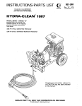
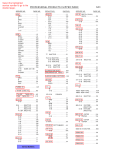
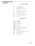
This manual contains IMPORTANT
WARNINGS and INSTRUCTIONSREAD AND RETAIN FOR REFERENCe
2104E.MODEL 800-053 SERIES "A"
2 150 p s i ( 1 50 bar) OPERA TlNG PRESSURE
2250 p s i (155bar).MAXIMUM WORKINGPRESSURE
DO not use chemicalsoragents
which are not
compatible with Buna-N and PVC or neoprene cover
of hose.
~ ~ J J j ~ ~ [~= ~; ' Q
b ~, ~&. j! ~ ~ ~
Fluids under high pressure from spray or leaks can
penetrate the skinandcauseextremelyserious
injury, including .the need for amputation.
.
Do not leave a pressurizedunit unattended. Shut off
the unit and release pressure before leaving.
NEVER point the spray gun at anyone or any part of
the body.
FORE
NEVER put hand or fingersover the spray tip.
Do not spray flammable liquids. Do not operatethe
engine where combustible fumes or 'dust may be
present.
NEVER try tostop or deflect leakswith your hand or
body.
GENERAL
ALWAYS have the tipguard in place when spraying.
NEVER run the unit with the belt guard
removed.
Keep clear of moving partswhen the unit
is running.
MEDlCAL TRE&TMEF%B
If any fluid appears to penetrateyour
treatmentinstructions
observe
detergent
manufacturer's
safety
precautions. Avoid getting detergent or other liquids
in your eyes. Follow the directions on thecontainer'
regarding
contact
with eyes,
nose,
and
skin,
breathing fumes, etc. Always wear full goggles to
protect your eyes from the spray as well as any debris
dislodged by the spray. If necessary, wear gloves or
other protective clothing. If. antidotes or treatment
are recommendbd, be prepared to use them.
skin, get
have' your doctor callthe
F.Sb,iTlONAE PQ@OM CENTER NETWORK
(412)6$1-6669
Avena ~ Q M ? ~ H E N T
DON'T spray toxic chemicals such as insecticide or
weed killer.
Even after you shut off the gasoline engine, there is
high pressure in the pump, hose and gun until you
release it by triggering the gun. So before removing
the spray tip or servicing the unit, alwaysshut offthe
unit and trigger the gun to release pressure.
This unit issupplied with an8-foot powercord made
up of four AWG No. 12 wires. The green wire of the
electric cord is connected to the unit chassis and
motor frame. The other three wires
are connected to
the starter switch.
Be sure
that
.all accessory items
and
system
components will withstand the pressure developed.
NEVER exceed the pressure ratingof anycomponent
in system. NEVER alter or modify equipment -your
personal safety, as well as thefunction
of the
equipment, is at stake.
Be sure to connectthepower cord to
the appropriate
approved plug to fit your requirements.
The starter switch has a built-in.circuit breaker that
will shut off the power to the unit whenever the
circuit is overloaded.
Before each use, check hosefor weak, worn or
damaged conditions causedby traffic, sharp corners,
pinching or kinking.Tighten all fluid connections
securelybefore.each .use. Replace anydamaged
hose.
Always check to be surethe switchis off and thatthe
hoses and electric cord are clear of moving parts
before plugging in the power cord.
IMPORTANT
-
United States Government safety standards have been
adopted under the Occupational Safety and Health
Act.
These standards particulsrlythe.General Standards, Part 1910, and the ConstructionStandards, Part 1926 should be consulted in connection with your use of airless spray equipment.
2 . 801-392
.
.
.
~~~
. .
.
.
~~
.
.
..
'
,
..-..
:
:
REMOVE TAPE
FROM PUMP CAP
I
SPRAY
GUN
!’
\SPRAY
Check Electrical Service and Plug In
Before plugging in thesprayer. be sure the electrical
service is3 phase 220 V, 60 HAC.20 Amp. With the
ON-OFF switch in the OFF position, plug the power
supplY cord into a grounded outlet. If you use an
extension cord, it must have 4 wires of a t least 12
gauge (2.5 mm2)and should notbe over.100ft (30.3
m) long.
r
.
L:’:
.
. , .. ...:,.
..,<
.~
HOSE
Connect To W a t e ~Supply
Do not exceed 16OoF (7OOC) ,water temperature to
pump in a direct supply system.
Install Hose and Spray Gun
Connect the spray hose tothe spray gun by inserting
at theend
of the hose intothe
quick
thepin
disconnect coupler on the gun. Connect the hose to
the fluid outlet in thesame way.
Connect a hose with at least a 3/4 in. (19 mm) ID
from your citywatersupply
to theunit’s 3/4 in.
garden hose threaded inlet. The supply hose should
not be more than 50 ft. (15 m) long.
Remove the tape from the cap on top of the pump.
NOTE:
Cleaning Accessories
For spraying detergent or other cleaning
solution, we
a chemical
injecior
kit. See
recommend
using
Accessories and instructionmanual801-192
for
installation and operation.
For a directsupply
system. your water
source at the unitmusthave a flow rateof
AT LEAST 5 GPM (19 LITER/MIN).
If your operating conditions are different from
above,
contact our Customer Service
Department
for
assistance.
For removing rust and old paint we recommend using
a water sandblaster.See Accessories and instruction
manual 801-190 for installation and operation.
801-392
3
OPERATlQM
: Startup
'
.
Beforestarting, be sure'to readthe safety warnings
and setup instructions.
Check the filter screen in the water inlet connection
as often as necessary, a t least daily. Do not operate
the unit with the inletand filter screen removed.
Turn on the water supply.
Trigger the gun to release any back pressure.
DO NOTtrytoadjusttheunloadervalveorchangethe
engine speed. Changing these settings rnay cause
excessive pressure, intermittent unloader operation,
on parts andwill void
wasted fuel and increased wear
the warranty.
CAUTION
' ,
I
Never run the cleaning unitdry. Costlydamage
to the pump will result. Always be sure water
supply iscompletelyturnedon before operating.
Inspect all connectionsforany
necessary.
leaks. Tighten if
Cleaning
For Hydra-Clean technique, see the Chemical
Injector manual, 801 -1 92.
'I
PUMP MUST NOT BE RUN DRY and must be drained
of water prior to exposure to freezing temperatures.
Use and storethe unit where itwill not be subjected
to freezing temperatures.If water does freeze in the
unit, thaw before trying to start. .A 50% anti-freeze
solution rnaybe
pumpedprior
to coldweather
storage.
Use only spray tips that are matched to the unit to
avoid excessive cycling and wear of the unloader
valve. See Accessories.
For abrasive cleaning, see the Water Sandblaster
90.
manual, 801 -1
CAUTION
WAffiNBNG
pour hot water on a frozen pump. A sudden
temperature change may crack the ceramic
Follow these precautions when removing and
installing nozzles:
1. Shutoff the cleaning unit andtriggerthegun
to relieve pressure. Engage the triggersafety.
2. Keep the nozzle and the tube pointed away
Do not pump caustic materials.
Before extended storage, flush the pump with light
oil.
from you and everyone else.
3. Do not put your handover the tip to push the
nozzle into place. Grasp it from the side and
keep your fingers away from the tip.
Avoid dragging hoseoveranabrasivesurfacesuch
as
cement. This causes excessive wearandshorter
hose life.
Clean the intake line strainer daily.
4. Do not let anyoneelse touch the spray valve
while you are cleaning nozztes.
5. Be sure the slipring is pushedforward to lock
the nozzle in place before triggering the
spray
gun.
Shutdown and. Care Of Unit
When unit is not in use, turn off water supply.
When shutting down for the
day or weekend, shut off
unit, shut off water supplyvalve, and trigger gun to
release pressure. Wipe off the unit witha damp rag.
Lubrication and Care
Fill pump crankcase to dot on oil,gauge window with
25 oz. (0.75 liters) of crankcase oil (part no. 801- 1 4 4 )
or equivalent SA€ 40 weighthydraulic oil with
antiwear and rust inhibitor additives. Change initial
fill after 50 hour running period. Change oil every 3
months or at 500 hour intervals.
WARNONG
1
NEVER alter adlustmentor modify the unloader
valve.
.
.. ...
~i
.... .. ..
. ~..: ..,.
i
PROBLEM
CAUSE
SOLUTION
-0w~pressure.
Worn nozzle.
Replace with nozzle of proper Size.
Belt slippage.
Tighten or replace; usecorrect belts and replacl
both at same time.
Air leak in inlet plumbing.
Disassemble, reseal, and reassemble
Clean, and adjust relief valve; check for worn
Relief valve stuck, partially
and
dirty valve seats. Kit available.
plugged or improperly adjusted,
valve seat worn.
Inlet suction strainer clogged 01 Clean. Use adequate size. Check more
frequently.
improper size.
.
.
Worn packing. Abrasives in
pumped fluid or severe cavitation. Inadequate water supply.
Install proper filter. Check flow available to
pump.
Fouled or dirty inlet or discharge
valves.
Clean inlet and discharge valve assemblies.
Worn inlet or discharge valves.
Leaky discharge hose.
Replace worn valves, valve seats and/or
discharge hose.
’ump runs extremely rough, Restricted inlet or air entering
Iressure low.
the inlet plumbing.
Proper size inlet plumbing; check for airtight
seal.
Inlet restrictions and/or air
‘eaks. Stuck inlet or discharge
talve.
Clean out foreign material, replace worn valves
-caking H.P. seals.
Replace seals.
Nater leakage from under
:he manifold.
vVorn packing.
Install new packing
Nater in pump crankcase.
Change oil at 3 month or 500 hour intervals usins
May be caused by humid air
:ondensing into water inside the Graco Crankcase Oil (other approved oil evenl
month or 200 hours) P.N. 801-144.
:rankcase.
:requent or premature
ailure of the packing.
Scored plungers.
Replace plungers,
3ver pressure to inlet manifold. Reduce inlet pressure.
lamaged or worn plungers.
Replace plungers.
4brasive material in the fluid
)eing pumped.
Install proper filtration on pump inlet plumbing,
ixcessive pressure-and/or tem. Check pressures andfluid inlettemperature; be
)erature of fluid being pumped. sure they are within specified range.
.
.:..
”
.. . .I..
.. : .
-.
;trow surging at the inlet
lnd low pressure on the
lischarge side.
h e r pressure of pumps.
Reduce pressure.
lunning pump dry.
Do not run DumD without water.
:oreign particles in the inlet or
lischarge valve, or worn inlet
Ind/or discharge valves.
Check for smooth lap surfaces on inlet and.
discharge valve seats. Discharge valve seats
and inlet valve seats may be lapped on a very
fine oil stone.
801-392
5
CAUSE
ectrtc motor w o n t run.
Electric motor runs, but
no output.
Power cord unplugged, or
building circuit fuse blown
Check, replace
Overload switch has opened.
Unplug power cord+, decrease pressure.
Power.cord unplugged, or
building circuit fuse blown,
Check, replace.
Overload breaker has opened.
Unplug power cord*, relieve pressure-allow
tO.CO01.
Extension cord.
Don't use more than 100ftof 12 ga extension cord.
Tip plugged.
Remove and clean.
Displacement pump frozen or
gear train damage.
Thaw.
sprayer
*This unit has an overload breakerbuilt into the switch
assembly. If it opens, unplug power cord and let
cool for 30 to 60 minutes. Also, try tocorrect the cause of overheating. Alwaysuse the lowest pressure setting
needed.
NOTE: A
M11 and M30 metricwrenches
required for servicing pump.
are
PUMP
Valves
Photo 1 and 2.
1 ) Remove the hex plug using an M30 wrench.
2) Examine O-ring under
plug
and
replace
if
evidence of cuts or distortion.
3) Remove valve assembly including
retainer,
spring, valve and valve seat from valve cavity.
NOTE: Valve assembly may come apart during
removal.
4) Replace valve parts with service kit (801-041)
including retainer, spring, valve, valve seat, oring and back-up-ring.
5) Replace valve cover and torque to 75 ft-lb (100
Nm).
Pumping Section
Photo 3.
1) Remove the four (4) hex nuts from the manifold.
2)Separate the manifold from thecrankcase.
NOTE: It may be necessary totapmanifold
lightly with mallet to loosen.
CAUTION
Keep manifold properly alignedwith ceramic
plungers when removing to avoid damage to
either plungers or seals.
3) Carefully examine each plunger for any scoring
and replace if necessary.
6
801-392
Plungers
Photo 4.
1 ) U s i n ga nM 1
1 wrench,
remove the plunger retainer.
2) Slide out theseal retainer with
oilwick
and rubberbarrier
slinger.
3) With a slight twistingmotion,
loosen the plungerfromthe
plunger rod and remove.
NOTE: The stud may remain
with
the
retainer
w h e rne m o v e d .
Disassemble
and
screw
s t u idn t o
plunger
rod
finger
tight.
4) Replace O-ring 'and backup
ring on plunger retainer.
wick by
soaking in oil.
6) Install new plunger.
7) Replace plunger retainer and
torque to 80 in-lb (9 Nm).
8)Installnew oil wick in seal
retainer.
9) Replace barrierslinger over
new plunger.
10) Lubricate each plunger sleeve
andcarefullyslidemanifold
onto crankcase.
5) Saturate newoil
Seals or V-Packings
Photo 5, 6, 7 and 8.
1) Remove C-ring fromseal case:
2) Then removethe lowpressure
seal from the seal case.
3) Unscrew the seal case from
themanifoldusing
a special'
key wrench (801-044).
4) Remove thehighpressure
seal and examine. Before
replacing, lubricate ID and OD
of new high-pressure seal and
press into manifold.
MOTE: A socket and extension may be used to
pressure seal from
manifold.
5) Install newO-ring on sealcase
k
9) Lubricate each plunger sleeve
andcarefullyslidemanifold
onto crankcase.
and lubricate OD of O-ring.
6) Screw seal case into manifold.
7) Lubricate ID and OD of low
,
..:
,
. ..,,., .
pressure seal and pressinto
seal case.
8) Replace C-ringholding
low
pressure seal in place.
.NOTE: W h e nr e p l a c i n g
manifold onto plungers,
ememe caution should
be exercised to avoid
damage to the seals.
10) Torqueallfour(4)boltsto240in-lb
(27 Nm).
NOTE: Carefullystudythe
order of respective
p a r tasnndo t e
position of sealsto
assure proper reassembly and operation.
801-392
7
8
801-392
i
!
Ref. No. 5 0 Includes items 51-66
,
62
63
-52
PART
REF
DESCRIPTION
QN
NO, NO.
26
27
28
29
30
31
32
34
35
36
37
40
41
42
PARTS LIST
PART
REF
DESCRIPTION
QTY
NO. NO.
1
HOSE & GUN
ASSY.
see aun
~
detail'for parts
PUMP,REPLACEMENTPARTS,
includes items 77-90
3 800-01 5 ANTI VIBRATION FOOT
4 800-036 CHASSIS
5 800-037 ELECTRIC MOTOR ASSY
6 801-390 BRACKET. spacer
8 801 -285 BELT, drive
9 801-231 LABEL. warning
10 801-140 LABEL. identification
11 801-129 LABEL, warning
13 801-131 PLATE, serial no.
14 801-221 CONNECTOR, crimp
16 801-379 SWITCH^ starter
17 801-382 CORD, power (8 f i lg)
18 801-380 STRAINRELIEF
19 801-292 SCREW, self tapping,
no. 6-32 NC x 1/2
20 801 -021 BOLT. carriage,
5/16-18 NCx 5"
21 801-088 SCREW, machine, hex hd.
hd. 5/16-18 NC x 1-1/2"
22 801-298 SCREW, machine, hex hd.
hd. 5/16-18 NC x 2-1/2"
23 801 -302 SCREW, machine hex hd.
5/16-18
.. . . . - .N.C .r. 1"
.
24 801-082 SCREW, machine, hex hd.
M6 x 30 mm
25 801-081 SCREW. machine, hex hd.
M8 x 20 mm
2
801-001
~~~~~
~
-
1
1
4
1
.1
1
2
2
1
1
1
2
1
1
2
2
2
4
1
4
4
2
44
801 -023
801-015
801-1 39
801.025
80.1-024
801 -01
2
801-367
801-004
801-381
801-135
801-137
801-018
801-364
801-365
801 -132
WASHER, flat, 1/4
WASHER, flat, 5/16
WASHER, IocIc 1/4
WASHER, lock, 5/16
NUT, hex, 5/16-18 NC
GROMMET
BUMPER
PULLEY, pump
PULLEY. rnntnr
HUB. pulley
KEY, pulley (2" lg)
BRACKET, tensioner
BELTGUARD, cover
BELTGUARD. baseplate
RIVET, drive
8
16
4
10
7
4
1
1
1
1
1
1
1
1
2
46 801 -008 LABEL. identification
47 801-388 LABEL, warning
48 801-389 LABEL. identification
50 801 -084 UNLOADER. includes itkms 51-66
51 801-045 . CAGE, valve
52 801 -046 . O-RING
53 801-047 . SPRING
54 801-048 , BALL
55 801-049 . SEAT
56 801-050 , O-RING.
57 800-012 . UNLOADERSUB58 ,801-059 . O-RING
59 801-060
HOUSING
60 801-OB1 . CYLINDER
61
O-RING
62
. PLUG
63
HOUSING VALVE
64
. SPRING
. VALVE'
65
. SEAT
66
67
COUPLER, male quick disconnect
68 801-105 NIPPLE, straight, brass,
1/2 NPT x 3- 1/2"
.69 801-106 TEE, brass, 1/2 NPT
70 801-236 NIPPLE, hex, steel, 1/2 z 3/8 NPT
71 801-108 NIPPLE, hex, brass,.l/4x 1/2 NPT
72 801-109 PLUG, hex, brass, 3/8 NPT
73 801-110 ADAPTER, 1/2 hose
74 801-1 11 NUT, brass, adapter
75 801-11~2 SCREEN, inlet
76 801-113 HOSE, coupled, 1 /2 NPT (MBE)
17-1/2" Ig
1
1
1
1
1
2
1
1
1
2
1
1
1
1
1
2
1
1
1
1
1
1
1
1
1
1
1
1
1
1
801 -392 9
ELECTRICAL SCHEMATIC
REF PART
NO. NO.
DESCRIPTION
Qn
Items 77-90are pump internal replacement parts.
See exploded view of pump for details.
77801-027
78801-028
79801-267
,
CAP
. O-RING, cap
. DISCHARGE
MANIFOI
n
80
81
82
83
84
85
86
87
... .- .
. - .- -
801-038 . RING, backup
89801-039
. O-RING
90801-040
. RETAINER, plunge1
88
1
1
1
3
3
3
3
3
3
3
3
3
3
3
Order parts by name and number. Always give the model
number and series letter of the assembly forwhich you are
ordering.
801-042 SEAL KIT
INCLUDES 3 SETS
SERVICE TOOLS
KEY WRENCH 801-044
EXTRACTOR TOOL 801-205
'80 801-392
PARTS DWAVVlMG
Gun and HoseAssern
'7
I-3
8
14
5
A
REF PART
NO. NO.
1
Repair Kit 801-083
Includes items A, B, C. D, E and F
SERVICE
1. Re'move the 8 screws from the
body halves (3)and
(4). See the Parts Drawing. Separate the body
halves.
2. Remove the Plug (14). spring (5)and ball (A) from
the valve body (G).
3. Remove the snap ring (6). Then remove the valve
seat (C) and'o-ring (0).
4. Remove the sleeve nut (1 1)and O-ring (E) with'the
actuator rod (F).
5.Afterinstallingthenewseat(C)andball(A),tapthe
balllightly with a hammer to assure a proper
seating between the ball andseat.
6. Reassemble in reverse order, using the remaining
new parts from the repair kit.
QTY
DESCRIPTION
SPRAY HOSE, 3/8" ID. 50 ft.
(15 ml Ig
2 800-017 SPRAY GUN, (replaceable parts
include items3-16)
3 801-244 . HANDLE, left
4 801-245 . HANDLE, right
5 801-249
;PRING
6
801-254
EVER
7 801-256
IEEDLE
8 801-262
IEX PLUG
9 801-261
IISCHARGE FIlTING
801-247
10
. VALVEBODY
11 801-253 . GUIDESLEEVE
12 801-246 . TUBE
13 801-263 . INLET FllTlNG
801-250
14
. CAP
-. ..
801.264
15
. SCREW
801-265
16
. SCREW
17 801-134 TUBE. 32"
18 801-029 GRIP
801-009
19
COUPLER,femalequickdisconnea
20'801 -090 COUPLER, male quick disconnect
801-073
21
HOUSING, nozzle
22"801-010
TIP, blasting; Oo
23'801 -01 1 TIP, cleaning; 15O
801-074
24
GUARD, tip
25 801-076 PLATE, warning
26 801-077 RIVET
801-103
27
NIPPLE, hex: 1/4 x 3/8" npc brass
28'801-091
COUPLER, male quick disconnect
801")7
'
1
1
1
1
1
1
1
1
1
1
1
1
1
1
7
1
1
1
3
1
2
1
1
2
1
2
1
2
Order parts b y name and series letter of the assemblyfor
which you are ordering.
*Recommended .'tool box" spare parts.
801-392 1d
ACCESSORIES (Must be purchased separately)
CHECK VALVE 801-133
CHEMICAL
INJECTOR
Prevent backup of contaminatedwaterintofresh
supply. lnstatl upstream from pump.
For injectingharshcleaningchemicalsdownstream
from pump.
WATER
SANDBLASTER
ADJUSTABLE SAND SAVER 800-031
800-103
For abrasive cleaning of stubborndirtand
KIT 800-182
For adjusting sand flow.
paint.
TECHNICAL DATA
MOTOR: 5 hp, 3 phase,
220 V, 60 Hz, 17 Amp
WATER PUMP:
WETTEDPARTS:
21 50 PSI (150 bar) rnax.
pressure; 4 GPM
(15 liter/min).
Stainless Steel, Aluminum,
Phenolic Plastic, Ceramic
Liners, Nitrile Rubber.
WEIGHT: 140 Ibs
OVERALL DIMENSION:
MAX. WATER TEMPERATURE:
Length: 36 in (914 mrn)
Width: 18 in (457 mm)
Height: 17 in (432.rnm)
16OoF (70°C)
INLET HOSE CONNECTION: 3/4-in. garden hose (f)
THE GRACO WARRANTY
GracoInc.warrantsa1Iequipmentmanufacturedbyitandbearingitsnametobefreefromdefectsin
material and workmanship under normal use and service. This warranty extends to the original
purchaserforaperiodof 12monthsfromthedateofpurchaseandappliesonlywhentheequipment
is installed and operated in accordance with writtenfactoryrecommendations.Thiswarrantydoes
not cover damageor wear which. in the reasonable judgment ofGraco. arises from misuse,
abrasion. corrosion, negligence. accident, substitution of non-Graco parts, faulty installation or
tampering.
This warranty isconditioned upon the prepaid return of the equipment claimedto be defective for
examination by Gram to verify the claimed
defect. If the claimeddefect is verified, Gram willrepair
or replace free of charge. any defective parts. The equipment will be returned to the original
purchaser transportation prepaid. If inspection of the equipment does not disclose any defect in
workmanshipormaterial,repairswill bemadeatareasonablechargeandreturntransportationwill
be charged.
EOUIPMENT NOT COVERED BY GRACO WARRANTY. Accessories or components of equipment
sold by Gracothat arenot manufactured by Graco (such as electric motors. switches, hose. etc.)are
subiect to the warranty, if any. of their manufacturer. Graco will provide purchaserwith reasonable
assistance in making such claims.
FaEtory Branches: Atlanta. Dallas, Detroit, Los Angeles. West Caldwell [N.J.)
Subsidiary and AMIIata Companies: Canada: England: Switzerland; France; Germany; Hong Kong:'Japan
GRACO BNC. P.O. ~ Q IWT
X
MBNMEAIPOLQS.
MN
%wo-na
. .
PRINTED IN U.S.A. 801-392 9-82
45-10043A