1
This manual contains IMPORTANT
WWARNINOS and INSTRUCTIONS
READ AND RETAINFORREFERENCE
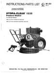
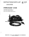
MODEL 800-048 SERIES "A"
2 150 psi (150 bar) OPERATING PRESSURE
2250psi (155 bar) MAXIMUM WORKING PRESSURE
~NJECTOQIMHAZARD
Fluids under high pressure from spray or leaks can
penetratetheskinandcauseextremelyserious
injury, including the need for amputation.
NEVER point the spray gun at anyone or any part of
Do notusechemicalsoragentswhicharenot
compatible with Buna-N andPVC or neoprene cover
of hose.
Do not leave a pressurized unit unattended. Shut off
the unit and release pressure before leaving.
the body.
FORE
NEVER put hand or fingers over the spray tip.
Do not spray flammable liquids. Do not operate the
engine where combustible fumes or dust may
be
present.
NEVER try to stop or deflect leaks with your hand or
body.
GENERAL
ALWAYS have the tip guard in place when spraying.
NEVER run the unit with the belt guard removed.
MEDlCAU TREATMENT
Keep clear of moving parts when the unit is running.
If anyfluidappearstopenetrateyourskin.
get
EMERGENCY M E D K A L C A R E AB ONCE.
DO MOK TREAT AS A SIMPLE GUT.
Tell the doctor exactly what fluid was injected.
treatmentinstructions
haveyourdoctorcallthe
For
RIAJIORIAU POISON CENTER NETWORK
($a2w~-666~
AVOID COMPONENT RUPTURE
Even after you shut off the gasoline engine, there is
high pressure in the pump, hose and gun until you
release it by triggering the gun. So before removing
the spray tip or servicing the unit,
always shut off the
unit and trigger the gun to release pressure.
Be sure
that
all
accessory
items
and
system
components will withstand the pressure developed.
NEVER exceed the pressure rating of any component
in system. NEVER alter or modify equipment -your
personalsafety,aswell
as thefunctionofthe
equipment, is at stake.
Beforeeach
use,checkhoseforweak,
worn or
damaged conditions caused by traffic, sharp corners,
pinchingorkinking.Tightenallfluidconnections
securelybeforeeachuse.
Replace anydamaged
hose.
O b s e r vdee t e r g e m
n ta n u f a c t u r e rs' sa f e t y
precautions. Avoid getting detergent or other liquids
in your eyes. Follow the directions on the container
regarding
contact
with
eyes, nose, and
skin,
breathing fumes, etc. Always wear full goggles to
protect your eyes from the
spray as well as any debris
dislodged by the spray. If necessary, wear gloves or
other protective clothing. If antidotes or treatment
are 'recommended, be prepared to use them.
DON'T spray toxic chemicals such as insecticide or
weed killer.
This unit is supplied with an 8-foot power cord made
up of three AWG No. 10 wires. The green wireof the
electric cord is connected to the unit chassis and
motor frame. The other three wires are connected to
the starter switch.
to the appropriate
Be sure to connect the power cord
approved plug to f i t your requirements.
The starter switch has a built-in circuit breaker that
will shut off the power to the unit whenever the
circuit is overloaded.
Always check to
be sure the switchis off andthat the
of movingparts
hosesandelectriccordareclear
before plugging in the power cord.
:
IMPORTANT
. .
United States Government safety standards have been adopted under the Occupational Safety and Health Act.
These standards - particularly the General Standards,Part 1910. and the Construction
Standards,Part 1 9 2 6 Should be consulted in connection with your use of airlessspray equipment.
2
801-457
... ... .
. ..
._i..
.
.
. ~.
. .... . ..
.
. - .
~
.
. ..
~
.
INSTALLATION
Check Electrical Service and Plug In
Before plugging in the sprayer, be sure the electrical
service is 1 phase 220
V, 60 H A C , 30 Amp. WitKthe
ON-OFF switch in the OFF position, plug the power
supply cord into
a groundedoutlet.Ifyouusean
extension cord, it must have 3 wires of at least 1 0
gauge (2.5 mm2) and should not be over100 ft (30.3
m) long.
Install Wheels and Handle
Slide the axle through the frame. Slide the wheels
and washers onto the axle and secure in place with
cotter pins provided. Install the hubcaps. Attach the
handle with thefour
screws, flatwashers,
lock
washers and nuts provided.
l,nstall Hose and Spray Gun
Connect the spray hose to the
spray gun by inserting
thepinattheend
of the hose intothequick
disconnect coupler on the gun. Connect the hose to
the fluid outlet in the same way.
For removing rust andold paint we recommend using
a water sandblaster.See Accessoriesand instruction
manual 801.190 for installation and operation.
Connect To Water Supply
CAUTION
Before attaching to water supply. check local
plumbing code regarding cross-connection to
water supply. Backflow check valve 801-133.
Do not exceed 16OoF(7OOC) water temperature to
pump in a direct supply system.
Connect a hose w i t h at least a 3 / 4 in. (19 mm) ID
3/4 in.
from your city water supply to the unit's
garden hose threaded inlet. The supply hose should
not be more than 50 ft. (15 m) long.
NOTE:
For adirectsupply
system,your
water
source at theunit must have aflow rate of
AT LEAST 5 GPM (19 LITER/MINI.
Remove the tape from the cap on top of the pump.
- .. .
$.
..'
i
'
Cleaning
Accessories
For sprayingdetergent or othercleaningsolution,we
recommend using a chemical
injector
kit.
See
Accessories andinstructionmanual801-192for
installation and operation.
If your operating conditions are different from
above.
contact
our
Customer
Service
Department
for
assistance.
CAUTION
OPERATION
will
spraying. for longer pump life. The pump
overheatifleftrunningforover
10 minutes
Startup
Before starting, be sure to read the safety warnings
and setup instructions.
1
.
.
Check the filter screen in the water inlet connection
as often as necessary, at least daily. Do not operate
the unit with the inlet and filter screen removed.
Turn on the water supply.
Trigger the gun to release any back pressure.
DONOTtrytoadjusttheunloadervalveorchangethe
engine speed. Changing these settings may cause
excessive pressure, intermittent unloader operation,
wastedfuelandincreasedwearonpartsandwillvoid
the warranty.
CAUTION
PUMP MUST NOT BE RUN DRY and must bedrained
of water prior to exposure to freezing temperatures.
Never run the cleaning unit dry. Costlydamage
to the pump will result. Always be sure water
supplyiscompletelyturnedonbeforeoperating.
Inspect allconnectionsforany
necessary.
Cleaning
For cleaning technique,
manual, 801 - 1 92.
For abrasivecleaning,
manual, 801- 1 90.
Use and store the unit where will
it not be subjected
to freezing temperatures. If water does freeze in the
unit, thaw before trying to start. A 50% anti-freeze
solutionmaybepumpedpriortocoldweather
storage.
leaks. Tightenif
see the Chemical lniector
Use only spray tips that are matched to the unit to
avoidexcessivecyclingandwearoftheunloader
valve. See Accessories.
see the Water Sandblaster
pour hot water on a frozen pump. A
sudden
temperaturechangemaycracktheceramic
plungers.
Follow these precautions when removing and
installing nozzles:
1 . Shut off the cleaning unit and trigger thegun
to relieve pressure.
Engage the trigger safety.
Do not pump caustic materials.
Before extended storage, flush the pump with light
oil.
2. Keep the nozzle a.nd the tube pointed away
from you and everyone else.
Avoiddragginghoseoveranabrasivesurfacesuchas
cement.Thiscausesexcessivewearandshorter
hose life.
3. Do not put your handover the tipto push the
nozzle into place. Grasp it from the side and
keep your fingers away from the tip.
Clean the intake line strainer daily
4. Do not let anyone else touch the spray'valve
while you are cleaning nozzles.
Lubrication and Care
Fill pump crankcase to dot on oil gauge window with
25 02. (0.75 liters) of crankcase oil (part no. 801-1 44)'
or equivalentSAE
40 weighthydraulicoil
with
antiwear and rust inhibitor additives. Change initial
fill after 50 hour running period.Change oil every 3
months or at 500 hour intervals.
5. Be sure the slip ring
is pushedforward tolock
the nozzle in place beforetriggering thespray
gun.
.
S h u t d o w n a n d Care Of Unit
When unit is not in use, turn off water supply.
When shutting down for the
day or weekend,shut off
unit, shut off water supply valve, and trigger gun to
release pressure. Wipe off the unit with
a damp rag.
4
WARMING
I
NEVER alter adiustment or modifv the unloader
I
Altering or adjusting unloader willnot increase
performance of unit.
I
1
valve.
801-457
.
.
. ... , . .. .
.
. .
._
..
..
.
.
.
...
.
. ..
~
.
.
.
.
.
. . .
. .
.
. I. ..
PROBLEM
CAUSE
SOLUTION
Low pressure.
Worn nozzle.
Replace with nozzle of proper size.
Belt slippage.
Tighten or replace; use correct belts and replac
both at same time.
Air leak in inlet plumbing.
Disassemble, reseal, and reassemble.
Relief valve stuck, partially
plugged or improperly adjusted
valve seat worn.
Clean. and adjust relief valve; check for worn
and dirty valve seats. Kit available.
Inlet suction strainer clogged o
improper size.
Clean. Use adequate size. Check more
frequently.
Worn packing. Abrasives in
pumped fluid or severe cavitation. Inadequate water supply.
Install proper filter. Check flow available to
pump.
Fouled or dim/ inlet or discharge
valves.
Clean inlet and discharge valve assemblies.
Worn inlet or discharge valves.
Leaky discharge hose.
Replace worn valves, valve seats and/or
discharge hose.
Pump runs extremely rough, Restricted inlet or air entering
the inlet plumbing.
uressure low.
Proper size inlet plumbing; check for airtight
seal.
Inlet restrictions and/or air
leaks. Stuck inlet or discharge
valve.
Clean out foreign material, replace worn
valve:
Leaking H.P. seals.
Replace seals.
Water leakage from under
the manifold.
Worn packing.
Install new packing.
Water in pump crankcase.
M a y be caused by humid air
condensing into water inside the
crankcase.
Change oil at 3 month or 500 hour interval
using Graco Crankcase Oil (other approved o
every month or 200 hours) P.N. 801-144.
Frequent or premature
failure of the packing.
Scored plungers.
?eplace plungers.
Over pressure to inlet manifold
?educe inlet pressure.
Damaged or worn plungers.
3eplace plungers.
Abrasive material in the fluid
being pumped.
nstall proper filtration on pump inlet plumbing
Excessive pressure and/or tern
perature of fluid being pumped.
:heck pressures and fluid inlettemperature; bc
jure they are within specified range.
Over pressure of pumps.
?educe pressure.
Running pump dry.
10 not run pump without water.
Foreign particles in the inlet or
discharge valve, or worn inlet
and/or discharge valves.
:heck for smooth lap surfaces on inlet and
iischarge valve seats. Discharge valve seats
m d inlet valve seats may be lapped on a very
ine oil stone.
Strong surging at the inlet
3nd low pressure on the
jischarge side.
SOLUTION
Check, replace.
building circuit fuse blown.
Overload switch has opened.
Unplug power cord'. decrease pressure
~
Electric motor stops while
spraying.
Electric motor runs, but
no output.
~~~
Power cord unplugged, or
building circuit fuse blown.
Check, replace.
Overload breaker.has opened.
Unplug powei cord'. relieve pressure-allow
to cool.
Extension cord
DonZ usemore than loOftoi 8 ga extension cord.
Tip plugged.
Remove and clean
Displacement pump frozen or
gear train damage.
Thaw,
'This unit has an overload breaker built into the switch assembly. itIf opens, unplug power cord and let sprayer
cool for 30 to 60 minutes. Also, try to correct the cause
of overheating. Always use the lowest pressure setting
needed.
NOTE:
A M11 and M30 metricwrenchesare
required for servicing pump.
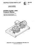
PUMP
Valves
Photo 1 and 2.
1 ) Remove the hex plug using an M30 wrench.
2 ) Examine
O-ring
under
plug
and
replace
if
evidence of cuts or distortion.
3)Removevalveassemblyincluding,retainer.
spring, valve and valve seat from valve cavity.
MOTE: Valve assembly may come apart during
removal.
41 Replacevalve
parts with service kit (801-041)
including retainer, spring,
valve,valveseat,
oring and back-up-ring.
5)Replace valve cover and torque to 75 ft-lb (100
Nm).
Pumping Section
Photo 3.
1) Remove the four {4) hex nuts from the manifold.
2) Separate the manifold from the crankcase.
NOTE: It maybenecessarytotap
manifold
lightly with mallet to loosen.
I
1
Keep manifold properlyaligned with ceramic
plungers when removing toavoid damage to
either Dlunclers or seals.
~
~~
~~
~
3) Carefully examine each plunger for any scoring
and replace if necessary.
6
801-457
. .... .. .
~
......
...
~
..
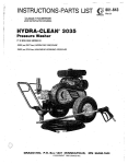
Plungers
Photo 4.
1 ) U s i n g. a n
M1 1 w r e n c h ,
remove the plunger retainer.
2) Slide out the
seal retainerw i t h
oilwickandrubberbarrier
slinger.
3).With a slight twisting motion,
loosen theplungerfromthe
plunger rod and remove.
MOTE: The stud may remain
with
the
retainer
w h erne m o v e d .
D i s a s s e m b laen d
screw
s t u idn t o
plunger
rod
finger
tight.
4) ReplaceO-ring
and back up
ring on plunger retainer.
5) Saturate
new
oil
wick
by
soaking in oil.
6) Install new plunger.
7) Replace plunger retainer and
torque to 80 in-lb (9 N m ) .
8) Installnewoilwickinseal
retainer.
9) Replace barrierslingerover
new plunger.
10) Lubricate each plunger sleeve
andcarefullyslidemanifold
onto crankcase.
Seals or V-Packings
Photo 5, 6,7 a n d 8.
1) Remove C-ring fromseal case.
2) Then remove the low pressure
seal from the seal case.
3) Unscrew the seal
case from
themanifoldusingaspecial
key wrench (801-044).
4)Remove thehighpressure
seal and
examine.
Before'
replacing, lubricate ID and OD
of new high-pressure seal and
press into manifold.
NOTE: A socket andextension may be used to
pressure
seal
from
manifold.
5)Install new O-ring on seal case
9) Lubricate each plunger sleeve
andcarefullyslidemanifold
onto crankcase.
10) Torqueallfour(4)bltsto240ir-lb
(27 Nm).
and lubricate OD of O-ring.
6) Screw seal case into manifold.
7) Lubricate ID and OD of low
NOTE: Carefullystudythe
NOTE: W h e nr e p l a c i n g
order of respective
para
t snndo t e
positionof
seals to
assure
proper
reassembly and operation.
manifold onto plungers,
enreme caution should
be exercised to avoid
damage to the seals.
pressuresealandpressinto
seal case.
8) Replace C-ringholding
low
pressure seal in place.
801-457
.. ~.
..
-
..~
.
,
.. . ,
,...
.
~..
.
. ..
.. _. .
.
.
.
.
.
"
7
... ...
,.
8
- ..,
801-457
"..
. ...
~,
~.
~
. .
. . .. .. . .
. .
-~.
. . . ..
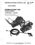
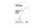
Ref. No. 50 Includes items 51-66, 79 & 81
62
63
fj/7g
52
64
65
REF PART
N O . NO.
66
56
59
24
801 -082
QTY
DESCRIPTION
SCREW, machine. hexhd,
30 mm
SCREW. machine, hex hd.
MB x 20 mm
WASHER. flat. 1/4
WASHER. flat, 5/16
WASHER, lock, 1/4
WASHER. lock, 5/16
NUT, hex. 5/16-18 NC
GROMMET
BUMPER
WHEEL
PULLEY, pump
PULLEY, motor
HUE. pulley
KEY, pulley (2” lg)
AXLE
WASHER, flat
BRACKET, tensioner
BELTGUARD. cover
BELTGUARD. baseplate
HUBCAP
PIN, cotter
RIVET, drive
LABEL, warning
LABEL. warning
LABEL. warning
LABEL, starting
UNLOADER, includes
items 51-66. 79. 81
CAGE, valve
O-RING
SPRING
BALL
SEAT
. O-RING
UNLOADER SUE-ASSY.
4
A!r ..6 x
25
801-081
26
27
28
29
30
31
32
33
34
35
36
37
38
39
40
42
43
44
45
46
47
48
49
50
801 -023
801-015
801 -1 39
801 -025
801 -024
801 -01 2
801 -367
801.241
801 -004
801-381
801-135
801 -1 37
801 -393
801 -235
801 -018
801 -364
801.365
801 -242
801 -243
801-132
801-130
801 -388
801-141
801-41 7
800-045
51
52
53
54
55
56
57
58
59
60
61
62
63
64
65
66
67
68
801 -045
801-046
801 -047
801 -048
801 -049
801 -050
801 -046
801 -059
801 -41
2
801-432
801 -062
801-063
801 -068
801-069
801 -070
801-071
801 -090
801-105
69
70
71
72
73
74
75
76
801-106
801-41 6
801-108
801-109
801-110
801 - 1 11
801-112
801-113
77
78
79
80
81
801-445
801 -450
800-044
801 -008
801 -465
41
8
PARTS LIST
REF PART
NO. N O .
1
parts
2
.DESCRIPTION
for
801-001
3
4
5
6
800-015
800-038
800-047
801-390
8 801-285
9 801-231
warning
801-140
10
11 801-129
12 801-022
13 801-131
14 801-221
801.394
15
16 801-379
17 801-448
18 801-446
19 801-292
20
21
.. . ’
800-039
801-088
22
801-298
23
801-302
CITY
HOSE & GUN ASSY. see gun
detail
PUMP, REPLACEMENT PARTS,
include items 77-90
ANTI VIBRATION FOOT
CHASSIS
ELECTRIC MOTOR ASSY
BRACKET. spacer
BELT. drive
LABEL.
LABEL, identification
LABEL. warning
.SCREW, machine, hex hd..
5/16-18 NC x 1-3/4”
PLATE, serial no.
CONNECTOR, crimp
HANDLE
SWITCH, starter
CORD. power (8 f t Ig)
STRAIN RELIEF
SCREW, self tapping.
no. 6-32 NC x 1/2
RAIL STIFFNER ASSY
SCREW, machine, hex hd,
5/16-18 N C x 1-1/2”
SCREW, machine. hex hd.
5/16-18 NC x 2-1/2”
SCREW, machine hex tid,
5/16-18 N C x 1”
1
1
2
1
1
1
2
2
1
1
4
1
2
1
1
1
2
2
1
4
1
4
2
8
18
4
12
9
4
1
2
1
1
1
1
1
2
1
1
~~
1
n.m~G
HOUSSG
CYLINDER
O-RING
PLUG
HOUSING VALVE
SPRING
VALVE
SEAT.
COUPLER, male quick disconnect.
NIPPLE, straight. brass,
1/2 NPT x/2”
3-1
TEE, brass, 1/2 NPT
NIPPLE,hex, steel, 1/2 x 3/8 NPT
NIPPLE, hex, brass, 1/4 x 1/2 NPT
PLUG.
hex.
brass.
.~3/8 NPT
ADAPTER, 1 /2 hose
NUT. brass, adapter
SCREEN,inlet
HOSE, coupled, 1/2 NPT (MBE)
17-1 /2”lg
LABEL. caution
O-RING
SLEEVE ASSY
LABEL
SCREW, button hd,
#6-32 NC x 5/16
~
801-457
..
.
..
.
.
..
... .. .
1
1
1
1
1
1
9
..
.
PARTS LIST (continued)
REF PART
ELECTRICAL SCHEMATIC
D.ESCRlPTlON
QTY
NO. NO.
Items 77-90 are pump internal replacement parts.
See exploded view of pump for details.
?E
77
~
-nn
". n l".
79
801.028
801-267
80
81
801-030
801-031
801-032
801-033
801-034
801-035
801-036
801-037
801-038
801-039
801-040
82
83
84
85
86
87
88
89
90
A..P
. C_.
. O-RING, cap
. DISCHARGE
1
1
MANIFOLD
WASHER
. SEAL
. RETAINER
. WASHER
1
3
3
3
3
3
3
3
3
3
3
3
.
. WICK.
~
.
RING, retaining
. PLUNGER
.
.
STUD
RING, backup
. O-RING
. RETAINER, plunger
Order parrs by name and number. Always give the model
number andseries letter of the assembly for which you are
ordering.
801-042 SEAL KIT
INCLUDES 3 SETS
OF PARTS
-r
77.
-86
90
SERVICE TOOLS
Rnl-nAA
.KEY
.- . WRFNCH
....-. - -.. - . - ..
EXTRACTOR TOOL 801-205
10
801-457
.. .. . ..... .
~
,
.
..
..
.
..
. .-.
,
.
..
. . . . . . ~.
~
..
.
.
.
.
..
.
...
.. .
~ . . ~
ij
/A)))
L @
Repair Kit 801 -083
Includes items A, B. C,
D, E
and F
PARTS
LIST
RE:F PART
DESCRIPTION
N<). NO.
k
2
1
SERVICE
1. Pressaccesspin(17)fromgunhandleandremove
access plate ( 4 ) by sliding plate towards back of
handle. Unscrew both short and long tubes with
fittings (12 and 15) from valve body (10); Valve
body should now slide out of the handle through
the access plate opening.
2. Remove the cap (14). spring (5) and ball (A) from
the valve body (10).
3. Remove the snap ring (e).Then remove the valve
seat
(C)and O-ring (13).
4. Remove t h e sleeve nut ( 1 1 )and O-ring (E) with the
actuator rod (F).
5. Afterinstallingthenewseat(C)andball(A),tapthe
."
....
balllightly with a hammertoassureaproper
seating between the ball and seat.
6. Reassemble in reverse order. Use pipe sealant on
5
6
7
8
9
10
11
12
13
14
15
16
17
..
18
19
20
21
22
23
24
25
26
27
28
an
801-007 SPRAY HOSE, 3/8" ID, 50 ft.
(1 5 m) IQ
800-043 SPRAY GUN, (replaceable parts
include items 3-18)
HANDLE
ACCESS PLATE
SPRING
TRIGGER
. NEEDLE
. HEX PLUG
. DISCHARGE FllTlNG
. VALVE BODY
. GUIDE SLEEVE
. TUBE
. INLET FllTlNG
801-250 . CAP
1
1
1
1
1
1
1
1
1
1
1
1
1
.
. SAFETY LATCH
. ACCESS PIN
. LATCH PIN
TUBE, 32"
GRIP
COUPLER, female quick disconnect
'801 -090 COUPLER, male quick disconnect
801 -073 HOUSING, nozzle
'801 -010 TIP, blasting; 0"
"801 -01 1 TIP, cleaning; 150
801-074 GUARD, tip
801-103 NIPPLE, hex; 1/4 x 3/8" npt; brass
*a01 -091 COUPLER, male quick disconnect
pipe threads on both short and long tubes(l2 and Order parts byname and series letter of the assembly for
which you are ordering.
151.
*Recommended "tool box" spare parts.
801.457
11
.. .
_.
ACCESSORIES (Must be purchased separately)
CHECK VALVE 801- 1 33
CHEMICAL
INJECTOR
Prevent back up of contaminated water into fresh
supply. Install upstream from pump.
For injecting harsh cleaning chemicals downstream
from pump.
WATER SANDBLASTER 8 0 0 - 1 03
ADJUSTABLE SAND SAVER 801-031
For abrasive
cleaning
For adjustingsandflow.
of stubborndirtandpaint.
KIT 8 0 0 - 1 0 2
TECHNICAL DATA
MOTOR:
5 hp, 1phase
2 2 0 V. 60 Hz, 27.5 Amp
WATER PUMP:
2150 PSI (150 bar) max
pressure; 4 G,PM
(15 liter/min).
WETTED PARTS:
WEIGHT:
StainlessSteel,Aluminum,
Phenolic Plastic, Ceramic
Liners, Nitrile Rubber.
195 Ibs (88 kg)
38 in (965 mm)
OVERALLDIMENSION:Length:
Width:27
in (686mm)
Height: 26 in (660 mm)
MAX. WATER TEMPERATURE:
INLET HOSE CONNECTION:
16OoF (70°C)
3/4-in. garden hose (f)
THE GRACO WARRANTY
GracoInc.warrantsallequipmentmanufacturedbyitandbear~ngitsnametobefreeframdefectsin
material and workmanship under normal use and service. This warranty extends to the original
purchaserforaperiodof12monthsfromthedateofpurchaseandappliesanlywhentheequipment
is installed and operated in accordance with writtenfactaryrecommendations.This warrantydoes
not cover damage or wear which. in the reasonable judgment of Graco. arises from misuse.
abrasion. corrosion. negligence, accident. substitution of non-Graco parts. faulty installation or
tampering.
This warranty is conditioned upon the
prepaid return of the equipment clatmed to be defective for
examination by Graco toverify the claimeddefect.
If the claimed defect is verified. Graco will repair
or replace free of charge. any defective parts. The equipment will be returned IO
the original
purchaser transportation prepaid. If inspection of the equipment does not disclose any defect in
workmanship or material, repairs will be madeata reasonablechargeandreturntranspartationwill
be charged.
..............
PURPOSE AND OF ANY NON-CONTR
EOUIPMENT NOT COVERED BY GRACO WARRANTY. Accessories or components of equipment
sold bv Graco that are not manufactured byGraco(such aselectric
motors. switches. hose.etc.)are
subject to the warranty.if any. of their manufacturer.Graco will provide purchaser wcth reasonable
assistance in making such claims.
Factory Branches: Atlanta. Pallas, Detroit, Lo6 Angeles. West Caldweli 1N.J.l
Subsidiary and AffiliateCompanies: Canada: England; Switzerland; France; Germany; Hong Kong: Japan
GRACO INC.
P.Q. BOX 1441 MORIRIEAPQLIS, MRI 55440-1444
PRINTED IN U.S.A. 801.457 Rev A
7/83
45-10051A
.
.~
.
-
..
........
. . . . . . . . . .
.....
."
.....