1
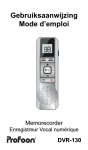
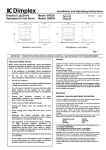
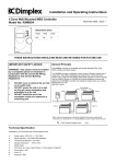
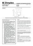
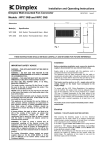
Installation and Operating Instructions
Passive Infra-Red Detector Switch
Issue 3 November 2006
Model No. DX4130
Height
130mm
Width
85mm
Depth
145mm
130mm
85mm
THESE INSTRUCTIONS SHOULD BE READ CAREFULLY AND RETAINED FOR FUTURE REFERENCE
IMPORTANT SAFETY ADVICE
General
•
The Dimplex passive infra –red detector switch has been designed to
enable Dimplex Quartz and ceramic heaters (or any other heater up to
3kW) It automatically switches the heater on and off, depending on
whether the area below the heater is occupied.
•
•
•
•
•
The installation of this product should be carried out
by a competent person or electrician in strict
accordance of the current IEE Wiring Regulations
The DX4130 is designed to be used in conjunction
with Dimplex heaters up to 3kW electrical loading.
Only to be used on a 220-240Volt A.C. ~ electricity
supply
Electricity supply must be isolated before
commencement of installation
Always isolate the detector switch and the heater
from the electricity supply before undertaking any
maintenance work
Must not be installed and used in the vicinity of a
bathroom or swimming pool
Features
•
•
•
•
•
•
Time delay adjustment
Full 180º coverage over 15m if required
Size of detection area can be reduced
Approved to VDE 0632 and IEC 669-2-1
Separate wall-box and plug in detector lead to simplify installation
IP54 rated
Contents
X1
X1
X1
X2
X3
X1
Instruction sheet
grey wall box with fixed terminal block
PIR switch with pre-wired plug in connection
screws to affix PIR switch to wall box
screw caps
lens mask
Installation
(Please also refer to the IMPORTANT SAFETY ADVICE)
Before undertaking installation work, ensure the electricity supply is disconnected from any relevant fixed wiring.
Supply cable is not provided with this product, and it should therefore be installed by a competent person or electrician
This PIR detector must be used on an A.C. ~ supply only
Dimplex Quartz and ceramic heaters operate by emitting radiant heat within a specific area or zone.
The beam of radiant heat will interfere with the correct performance of the PIR detector unless the PIR detector is mounted outside the ‘throw’ of
radiant heat. It is therefore essential that the PIR detector is mounted as outlined below:
1.
2.
3.
4.
For installation of Quartz and ceramic heaters, please refer to the relevant installation instructions.
The PIR should be positioned to cover the desired sensing area without obstruction, avoiding the direct ‘throw’ of the heater.
The PIR should be wired directly back to a type C MCB or 13 amp re-wireable fuse. The cable should not exceed 2.5mm².
Remove screws and disconnect the plug connecting the detector to the key box. When removing the detector head, the latch on plug
should be released as indicated. (see Fig.1.)
Detector Head Plug
Press Down
Fig.1.
Installation continued
5.
6.
7.
8.
9.
10.
Insert top screw into the wall, allowing it to protrude by approximately 3mm.
Hook wall box on to screw using keyhole slot provided.
Mark position of remaining fixings, remove box and complete fixing.
Fix the wall box to the wall, ensuring the drain hole is at the bottom.
Cable entries are made to the base of the box, using the holes provided.
Connect circuit wiring to terminal block. (see Fig.2.)
N = Neutral to load
N = Supply Neutral
N
N
SLI
L
= Earth terminal
SLI = Supply to load
L = Supply live
11. Plug detector head into the back box socket.
Secure detector to wall box with screws provided and cover screws with screw caps.
Adjusting PIR Range
Limit the range and angle of detection as appropriate by adjusting the detector head and by using the lens masking plates
provided. Cut the appropriate segments from the lens mask to cover the area of the lens that requires masking.
A1
B1
C1
A2
B2
C2
90º
45º
15m
A3
B3
C3
A4
B4
C4
0
12m
45º
3m
3m
C1
B1
12m
15m
90º
C4
B4
C3
C2
A1
A4
B2
45º
Long Range 6-15 metres
Inner Range 3-12 metres
Short Range 0-3 metres
90º
B3
A2
A3
45º
0
15m
15m
90º
45º
Masked Areas
AC
A4
B3
B4
C3
C4
A1
B1
C1
Masked Areas
A2
B2
C2
A4
B4
C4
Testing
1.
2.
3.
5
Set the light level
to maximum (clockwise), and the time on
to minimum (anti-clockwise).
Move in and out of detection pattern checking the PIR detector switches load on and then off. Once the detection area has been set
satisfactorily, adjust the time (blue knob) to the desired level. For your convenience optimum settings have been indicated.
If the unit does not operate, refer to the check list and fault finding list.
Check List
1.
2.
3.
Check the supply to the detector
If the unit is being tested during daylight , ensure that the photocell has been adjusted in accordance with point 1 in the ‘Testing’
section.
Check detector is connected to the heater correctly
Fault Finding List
Problem
Solution
The unit will not switch on
•
•
•
•
Unit is detecting at too long a range
Check power is supplied to the unit
Check the plug in connection from the detector head is inserted in to the wall box correctly
Check to see that the lamps are fitted correctly to the heater(s)
Check mounting height and adjust angle of the unit downwards to reduce range (note the unit is
designed to switch at a maximum of 15 metres with 170Ib (77kg) person walking at 90º to the
unit. Alternatively fit an appropriate mask.
IMPORTANT: at 10ºC this unit may detect in excess of 20 metres.
Unit switches on for no apparent
reason
•
Check the unit is not sited near any vents or heating flues
•
Infra-red patterns are given off by electrical appliances
NOTE: to reduce sensitivity, blank off areas C1, C2, C3, C4 of the lens mask
Unit will not switch off
•
Are you standing by the detection zone? Whilst you are moving in and out of the detection area
the unit will continue to detect. The heater on time is from the last moment detection was made.
Technical Specification
Switching capability – Up to 3kW
Operating Power – 3kW
Detection Range – 15 metres maximum
Detection Angle - 180º
Heater on time – Adjustable to 10 seconds, 60 seconds, 3.5 minutes, 6 minutes, 9 minutes, 12 minutes, 13.5 minutes,
16 minutes, 21 minutes (approximately)
IMPORTANT: When unit is first connected to the mains the light will switch on – even in daylight.
Allow unit to reset before testing
After Sales Care
Your product is guaranteed for one year from the date of purchase.
Within this period, we undertake to repair or exchange this product free of charge (subject to availability) provided it has been
installed and operated in accordance with these instructions.
Your rights under this guarantee are additional to your statutory rights, which in turn are not affected by this guarantee.
Should you require after sales service you should contact the supplier through whom you purchased the product or contact our
customer service help desk on 0845 600 5111. It would assist us if you can quote the model number, series, date of purchase,
and nature of the fault at the time of your call. The customer service help desk will also be able to advise you should you need to
purchase any spares.
Please do not return a faulty product to us in the first instance as this may result in loss or damage and delay in providing you
with a satisfactory service.
Please retain your receipt as proof of purchase
Glen Dimplex UK Ltd
Millbrook House
Grange Drive
Hedge End
Southampton
SO30 2DF
UK customer helpline (8.00AM-6.00PM Mon-Fri; 8.30AM-1.00PM Sat)
Customer helpline
Tel. 0845 600 5111
Fax. 01489 773053
e-mail. [email protected]
Republic of Ireland
Tel. 01 842 4833
[C] Glen Dimplex UK Ltd.
All rights reserved. Material contained in this publication may not be reproduced in whole or part, without the prior permission in writing from
Glen Dimplex UK Limited.