1
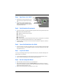
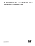
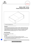
QUICK START GUIDE
[ Quick Start Guide ]
FIBRE CHANNEL SWITCH INSTALLATION
z
Quick Start Guide
Installation Instructions
Congratulations on your purchase of the QLogic 3810 Fibre Channel Switch. This guide describes the steps to install
and activate your new switch using a Windows® workstation. For advanced options and instructions (including Solaris®,
Linux®, and Mac OS X® installations), refer to the QLogic 3810 Fibre Channel Switch Installation Guide, which is available
at www.qlogic.com.
NOTE
Do not apply power to the switch until instructed in Step 4.
Step 1. Verify the Package Contents
The QLogic 3810 Fibre Channel Switch is shipped with the following items:
1
1
4
8
QLogic 3810 Fibre Channel Switch
AC Power cord
Rubber feet
SFP optical transceivers (optional)
NOTE
Some models include SFPs, or SFPs can be ordered separately. If you ordered SFPs separately, they will arrive in
a different package.
Step 2. Mount the Switch
❑
For a surface mount, attach the rubber feet to the locations on the bottom of the switch. For a rack mount, install
the QLogic 3800/5800 Series rail kit and the switch in a standard 19" rack as described in the QLogic 3800/5800
Series Fibre Channel Switch Rack Mounting Guide.
Step 3. Install Transceivers
An SFP transceiver is required for each SFP port that will be connected to a device. The QLogic 3810 Switch SFP ports
support 2Gbps, 4Gbps, and 8Gbps transmission. Do not attempt to configure a port to 1Gbps that has an 8Gbps SFP
installed; doing so will down the port.
❑
2
To install an SFP transceiver, insert the transceiver into the switch port, and gently press until it snaps in place.
The transceiver will fit only one way. If the transceiver does not install under gentle pressure, flip it over and try again.
Step 4. Apply Power to the Switch
INPUT POWER
LED
❑
Plug the AC power cord into the switch and into a wall
outlet or power strip. Verify that the Input Power LED
is lit.
HEARTBEAT
LED
❑
The switch runs its self tests, and begins normal
operation—this may take a few minutes. Verify that
the Heartbeat LED is blinking (once per second), and
the System Fault LED is not lit.
SYSTEM
FAULT LED
Step 5. Verify Workstation Requirements
❑
❑
Verify that your workstation can support the QuickTools™ application with the following minimum requirements:
■
Windows® 2003 or Windows XP SP1/SP2
■
512MB memory minimum; 1GB recommended
■
1GHz processor
■
Video card with 256 colors
■
RJ-45 Ethernet port
■
Internet Browser: Microsoft® Internet Explorer® 6.0 and later, Firefox® 1.5 and later, Safari® 1.0 for Windows
■
Java™ 2 Standard Edition Runtime Environment 1.4.2 to support the Web applet
The default IP address of a new switch is 10.0.0.1. Ensure that your workstation is configured to communicate
with the 10.0.0 subnet.
Step 6. Connect the Workstation to the Switch
❑
Connect the workstation to the switch using an Ethernet cable—the switch automatically recognizes both straight
and cross-over cables. If you are using a Windows workstation, you must have a live Ethernet connection when
the workstation powers up.
Step 7. Log In to the Switch
You can log in to and manage the switch using the command line interface (CLI) or the QuickTools Web applet. This
guide describes the use of QuickTools.
❑
To start the QuickTools Web applet, open an Internet browser, and then type the default IP address 10.0.0.1.
❑
Log in to the switch using the default user name (admin) and password (password).
Step 8. Run the Configuration Wizard
❑
Obtain the IP address and subnet mask from your network administrator.
❑
Open the QuickTools Wizards menu and select Configuration Wizard. Follow the instructions to set network
parameters and the password. The default user name is admin; the default password is password. Changing the
IP address will terminate the QuickTools session.
❑
Open an Internet browser and type the new IP address to log in to switch.
3
Step 9. Connect Devices
❑
Connect fiber optic cables between the installed transceivers and their corresponding devices. Each port
auto-negotiates the correct port type with the connected device.
Congratulations
You have successfully installed your QLogic 3810 Switch.
Please feel free to contact your QLogic approved reseller or QLogic Technical Support at any phase of integration
for assistance. QLogic Technical Support can be reached by the following methods:
Web: http://support.qlogic.com
E-mail: [email protected]
The QLogic knowledge database contains troubleshooting information for the QLogic adapters. Access the data base
from the QLogic Support Web page, http://support.qlogic.com. Use the Support Center search engine to look for
specific troubleshooting information.
Corporate Headquarters
QLogic Corporation
26650 Aliso Viejo Parkway
Aliso Viejo, CA 92656
949.389.6000 www.qlogic.com
International Offices
UK | Ireland | Germany | France
India | Japan | China
Hong Kong | Singapore | Taiwan
© 2012 QLogic Corporation. QLogic, the QLogic logo, and QuickTools are registered trademarks or trademarks of QLogic
Corporation. Microsoft, Windows, and Internet Explorer are registered trademarks of the Microsoft Corporation. MacOSX
and Safari are registered trademarks of Apple Computer, Inc. Linux is a registered trademark of Linus Torvalds. Firefox
is a registered trademark of the Mozilla Foundation. Java and Solaris are registered trademarks of Oracle Corporation.
All other brands and product names are trademarks or registered trademarks of their respective owners. Information
supplied by QLogic is believed to be accurate and reliable. QLogic Corporation assumes no responsibility for any errors
in this brochure. QLogic Corporation reserves the right, without notice, to makes changes in product design or
specifications.
*59267-01
59267-01 A
A*