1
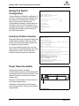
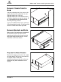
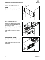
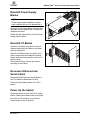
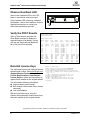
A Simplify SANbox 9000™ Series Chassis Replacement Guide 1. Chassis with shipping covers WARNING!! This guide describes the procedure for one person to replace a SANbox 9000 Series chassis. It involves removing blades while the switch is in the rack, and then removing the empty chassis. Depending on the location of the switch in the rack, it may be easier to remove the populated switch from the rack first. In this case, to avoid injury or damage to the switch, arrange for the help of an assistant when removing or installing a populated switch. Tools Required Crosshead screw driver, medium ESD wrist strap CAUTION! Always use an ESD wrist strap when handling and blades and modules. To avoid damage to the I/O blades, CPU blades, Power Supply blades, and Fan blades, do not touch the circuit boards and electrical components. 59244-00 A 1 *59244-00 A* A SANbox 9000™ Series Chassis Replacement Guide Backup the Switch Configuration Create a backup of the switch configuration if one does not already exist and upload it from the switch to the management workstation. Open a Telnet session and enter the Config Backup command to create the file on the switch. Then use FTP to upload it to the management workstation. You can accomplish the same task using the Archive function of the QuickTools interface. Inventory Feature Licenses Enter the Feature Log command to display the installed feature licenses. Make note of the license keys so that the feature licenses can be installed in the new chassis. If you have installed license keys, enter the Show Version command and make note of the chassis serial number. You will need this number to request new license keys later. Switch login: admin Password: password Telnet Sanbox #> admin start Sanbox (admin) #> config backup SANbox (admin) #> exit ======================================= ftp <ip_address> FTP User: images Password: images ftp> binary ftp> get configdata ftp> bye SANbox #> feature log Mfg Feature Log: ---------------Customer Feature Log: --------------------1) day mon date hh:mm:ss year - Switch Licensed for HyperStack(tm)capability 200000-LCRXIET7KXSXO SANbox # > show version ***************************************************** * * * Command Line Interface SHell (CLISH) * * * ***************************************************** SystemDescription SANbox 9000 FC Switch EthNetworkAddress 10.20.11.192 (use 'set setup system EthMACAddress 00:c0:dd:00:71:ee WorldWideName 10:00:00:c0:dd:00:71:ed ChassisSerialNumber FAM033100024 SymbolicName SANbox ActiveSWVersion V6.2.x.x.xx.xx ActiveTimestamp day month date time year DiagnosticsStatus Passed Power Down the Switch Isolate the switch from the fabric. Confirm that the primary CPU Heartbeat LED is showing the normal 1 blink per second. This allows the switch to correctly report power supply status. Move the On/Off switch to the Off position on both Power Supply blades. 1 Unfasten the restraint bails from the plugs, and unplug the power cords from both Power Supply blades. 1. Heartbeat LED 2 59244-00 A A SANbox 9000™ Series Chassis Replacement Guide Disconnect Ethernet and Serial Cables Disconnect Ethernet cables from CPU blades and the Maintenance Panel. Disconnect HyperStacking cables from the CPU blades. Disconnect Fibre Channel Port Cables IO0 Label I/O blades by slot number. I/O blade slots are numbered IO0–IO7. 0 8 7 15 IO1 Label Fibre Channel port cables by slot number and port number. 4-Gbps I/O blade ports are numbered 0–15 from top to bottom, left to right. 10-Gbps I/O blade ports are numbered 0–4, top to bottom, left to right. Disconnect Fibre Channel port cables. Remove I/O Blades Connect an ESD wrist strap to a ground point on the rack. Rotate the I/O blade latch to the full open position. Pull the I/O blade by the latch to disengage the I/O blade from the midplane. Carefully slide the I/O blade out of the chassis. Remove I/O blade panels in the same way. 1 1. Latch, IO0 blade 59244-00 A 3 A SANbox 9000™ Series Chassis Replacement Guide Remove Power Supply Blades WARNING!! The Power Supply blade faceplate and internal surfaces can become very hot. Handle with care. 1 Rotate the latch to the full open position. Pull the Power Supply blade by the latch to disengage the blade from the midplane connector. Carefully slide the Power Supply blade out of the chassis. 1. Latch, PS0 blade Remove the Fan Blades Rotate the latch to the full open position. Pull the Fan blade by the latch to disengage the blade from the midplane connector. Carefully slide the Fan blade from the chassis. 1 1. Latch, FAN0 blade Remove CPU Blades Label the CPU blades, CPU0 and CPU1. Rotate the latch to the full open position. Pull the CPU blade by the latch to disengage the blade from the midplane as shown. 2 1 1. Latch, CPU0 blade 4 2. CPU1 blade 59244-00 A A SANbox 9000™ Series Chassis Replacement Guide Remove Chassis from the Rack Using a crosshead screw driver, remove the screws that secure the chassis to the rack. Slide the chassis out of the rack. 1 Slide the chassis out of the cabinet until the rail latches drop down to stop the chassis. Lift up on the latches on both sides and finish removing the empty chassis. If you have installed license keys, make note of the chassis serial number. You will need this number to obtain new license keys later. 1. Latch Remove Brackets and Rails Make a note of the location and orientation of the brackets and the rails. Remove the brackets and rails from the chassis and set them aside along with the screws. You will install them on the new chassis. 2 1 1. Bracket 2. Rail Prepare the New Chassis Remove the shipping covers from the ends of the new chassis. Each cover is secured with six screws, three on each side. Install the brackets and the rails on the new chassis as they were installed on the old chassis. 1 1 1. Covers 59244-00 A 5 A SANbox 9000™ Series Chassis Replacement Guide Install New Chassis in the Rack Slide the new chassis into the cabinet rails. Fasten the switch rails to the cabinet rails with two screws. 1 1 1. Screws Reinstall CPU Blades Install the CPU blades in slots CPU0 and CPU1 of the new chassis according to the labels on the CPU blades. Open the CPU blade latch and slide the CPU blade into the chassis until it makes contact with the midplane connector. Rotate the latch to lock the CPU blade in place. Reinstall Fan Blades Open the Fan blade latch and slide the blade into the chassis until it contacts the midplane connector. Rotate the latch right-to-left to lock the Fan blade in place. 6 59244-00 A A SANbox 9000™ Series Chassis Replacement Guide Reinstall Power Supply Blades NOTE Power Supply blade installation is easier when installed after the Fan blade below it. Open the Power Supply blade latch and slide the blade into the chassis until it contacts the midplane connector. Rotate the latch right-to-left to lock the Power Supply blade in place. Reinstall I/O Blades Install the I/O blades and panels in the new chassis matching the slot label on the blade with the chassis slot. Slide the I/O blade into the slot guide until it makes contact with the midplane connector. Rotate the blade latch upward to lock the I/O blade in place. Reconnect the Fibre Channel port cables according to their labels. Reconnect Ethernet and Serial Cables Reconnect the Ethernet and serial cables to the CPU blades or Maintenance Panel. Reconnect HyperStack cables to the CPU blades. Power Up the Switch Reconnect power cords to the Power Supply blades. Fasten the restraint bails on the plugs. Move the On/Off switches on both Power Supply blades to the On position. 59244-00 A 7 A SANbox 9000™ Series Chassis Replacement Guide Observe Heartbeat LED Observe the Heartbeat LED on the CPU blade. It should blink once per second. If the Heartbeat LED is showing a different blink pattern, refer to the Installation Guide for diagnostic procedures or contact your authorized maintenance provider. 1 1. Heartbeat LED Verify the POST Results Open a Telnet session and enter the Show Blade command to display the diagnostic status for all blades. You can also use the Switch tab and Blade Info tab of the QuickTools interface. telnet 10.0.0.1 Switch Login: admin Password: password SANbox #>show blade Blade ID ----IO0 IO1 IO2 IO3 IO4 IO5 IO6 IO7 +CPU0 CPU1 PS0 PS1 FAN0 FAN1 MP Reinstall License Keys The old license keys are not valid with the new chassis serial number. Visit www.QLogic.com (Support/Product Feature Activation/ License Key Activation Center/Replace License Keys) to obtain new license keys to replace those installed on the original chassis. Blade Type ---FC4G16 FC4G16 * * * * * * CPU CPU PSFB PSFB FANFB FANFB MP Port Admin Range State ----- ----0-15 Online 16-31 Online * Online * Online * Online * Online * Online * Online N/A Online N/A Online N/A N/A N/A N/A N/A N/A N/A N/A N/A N/A Oper Fault Temp Voltage State Status Status Status ---------- ------ -----Online None Normal Good Online None Normal Good NotInst * * * NotInst * * * NotInst * * * NotInst * * * NotInst * * * NotInst * * * Online None Normal Good Online None Normal Good N/A None N/A N/A N/A None N/A N/A N/A None N/A N/A N/A None N/A N/A N/A None N/A N/A SANbox #> admin start SANbox (admin) #> feature add #-XXXXXXXXXXXXX License upgradefor HyperStack(tm) capability. This feature upgrade does NOT require a switch reset. Do you want to continue with license upgrade procedure? (y/n): [n] y Log Msg: [day mon date hh:mm:ss.sss CST year] [C][8400.006B][Switch][Upgrading License for HyperStack(tm)capability] Log Msg: [day mon date hh:mm:ss.sss CST year] [C][8400.0047][Switch][New licenses are being installed] You will need the following information: Original chassis serial number New chassis serial number (Show Version command) Your email address With the new license keys, enter the Feature Add command to install license keys that were installed on the original chassis. Copyright© 2007 QLogic Corporation. SANbox is a trademark of QLogic Corporation 8 59244-00 A