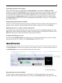
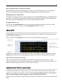
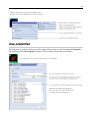
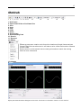
1
Lasershow Designer QuickShow And Flashback 3 SE User Manual Due to our policy of continuous product improvement, information in this manual is subject to change without notice. Intellectual Property notice and credits QuickShow is copyright © 2008-2010, Pangolin Laser Systems, Inc. All rights reserved. QuickShow User Interface Patent Pending. QuickShow was written by Alexey Sinitsyn, Valery Furmanov and William R. Benner, Jr., with development assistance and testing by Derek Garbos. Contents Introduction In this package CD-ROM contents Functions 5 5 6 Installing USB driver installation Installing QuickShow software 7 7 Getting started Introduction Quick Setup 9 10 Settings Settings menu Projector Settings QuickTargets Projection Zones Basic functions Main control window Toolbar Cue grid Laser Preview window Controlling cues during playback 13 14 17 18 23 23 26 29 29 Live-control tab Overview Master and Cue controls Size controls Position and Rotation controls Color controls Playback controls QuickTools Overview QuickText QuickShape QuickTrace QuickTargets QuickTimeline QuickFX Advanced Tools Overview Cue Properties Laser Frame/Animation Editor Advanced Text Editor Advanced Shape (abstract) editor Advanced Clock editor Effect Editor 32 33 34 36 36 37 38 40 41 43 44 45 45 46 48 59 61 62 63 Appendix XD Memory Module Status lights ILDA output assignment 69 69 70 5 Introduction The Flashback 3 product line is the smallest, easiest and most economical way to add high-quality graphics and beams to a stand-alone laser projector. In fact, the Flashback 3 is so impressive, that it won the ILDA Hardware Product Of The Year Award in 2006. This credit-card sized wonder can play laser graphics, beams and even complete Pangolin-quality shows. No extra computer hardware is needed – the tiny Flashback 3 has everything you need to control your laser projector. In this package Included in this package you will find a CD-ROM, and the Flashback 3-SE, which is the combination of Flashback 3 base board, a USB daughterboard, a differential output daughterboard, and a XD memory module. CD-ROM contents The CD-ROM included with this package includes: Lasershow Designer QuickShow program Workspace file USB drivers for Flashback 3-SE 6 Functions Lasershow Designer QuickShow – a PC application for full control of Flashback 3-SE, allows: Trigger cues by clicking on buttons with the mouse Create and edit the frames and animations on line (real time editing) Live control of many effects parameters during cue playback Live total control of the Flashback 3-SE The FlashBack 3 SE hardware contains the following basic functions: USB power supply XD socket with ability to accommodate modules from 32MB to 128MB 12-bit X and Y outputs with differential voltage level of +/-5V 8-bit Red, Green, Blue and Intensity outputs with single-ended voltage level of 0 to +5V TTL-level Shutter signal High speed connection between Flashback 3-XE and PC (480 Mb/s) The DMX daughterboard adds the following functionality to Flashback 3: DMX-512 control – allows using an industry standard control protocol Real time geometry manipulation – size, position, rotation control * A daughter board is also available that will provide differential outputs for X and Y. Contact Pangolin if you are interested in this option. Software and Hardware Installation To use the Flashback 3-SE, you will need to install QuickShow software first, and then, while the CD ROM is still inside the drive, connect the supplied USB cable to one USB port available on your computer. QuickShow requires Windows XP or later. You will also need to connect the DB25 to a projector. The DB25 connector is connected as a QM2000/ILDA-compatible connector, complete with differential outputs for X and Y. Installing the QuickShow software The QuickShow software installation should begin installation when the CD is inserted. To manually install the QuickShow software application, simply copy the QS folder from the CD ROM to your computer. USB driver installation When you connect the Flashback 3-SE to USB port of your computer, the ‘New Hardware’ wizard will appear. You should not use automatic install procedure. Instead, you should point the wizard to the USB driver directory on the CD-ROM. 9 QuickShow Introduction QuickShow was designed to be an easy-to-use program for anyone wanting to control lasers -- including beginners who have never used a laser before, as well as to the most experienced laser operators. Although ease-of-use was the guiding principal behind QuickShow, it is still quite powerful since it is based on Pangolin's new BEYOND calculation engine and it has many advanced features not found in any other product. Designed by laserists for laserists During the development of QuickShow, we consulted with laserists of all kinds, including everyone from hobbyists playing shows in their garages, all the way up to top-level Laser DJs, including Glenn Turner of Oracle Projects and Derek Garbos of Garbos Consulting. Derek contributed hundreds of suggestions and he also created the demonstration workspace that comes with QuickShow. More help available on the Laserchat forum Although we intended QuickShow to be a program friendly enough for beginners to use, QuickShow is also a very deep program. It is not likely that you will ever exhaust the power and capabilities of QuickShow, no matter what your application. As such, we encourage users to check out the Pangolin Laserchat forum, which has many topics intended to help people gain a greater understanding of QuickShow as well as other Pangolin-related products. The Laserchat forum can be found on the Pangolin web site. System Recommendations Dual-core processor is recommended Unlike most of Pangolin's past developments, QuickShow uses the PC to do all of the laser calculations and processing, while output boards such as the FB3 are used only for color conversion and final laser output. Because of this, we recommend you use a dual-core processor (Intel Centrino Duo or Core 2 Duo or equivalent AMD) for best results. Monitor resolution of 1024 by 768 or higher is recommended QuickShow was designed to work with a single monitor with a resolution of 1024 by 768 or higher. QuickShow will work with a lower resolution, but some of the features on the lower portion of the screen will be unavailable. 10 Quick Setup The very first time you run QuickShow, the Quick Setup wizard will greet you. (Quick Setup can also be accessed at any time in the Help menu.) The purpose of the QuickSetup wizard is to help you to configure the most important parts of QuickShow to your needs and the needs of your projector. Step 1: Specify a user level The first step in the process is to familiarize QuickShow with the type of user you are. When choosing a user level, you should be as honest as possible, since QuickShow will tailor the features you see based on your user level. If you are a beginner and you tell QuickShow that you are an advanced user, you might get confused by the advanced tools seen at the Advanced level. 11 Step 2: Indicate the type of scanners you have The second step in the process is to familiarize QuickShow with the type of scanners you have. THIS IS VERY IMPORTANT! If you have low performance scanners and you tell QuickShow that you really have high performance scanners, QuickShow may drive the scanners too hard, which may cause excessive wear or heat. So when indicating the type of scanners you have, be as careful as possible. The high performance setting is only for American-made scanners, as well as the most expensive German and Chinese scanners. Step 3: Indicate the number of lasers in your projector The third step in the process is to familiarize QuickShow with the number of lasers in your projector. This is important because if you only have a single-color laser and you tell QuickShow that you really have an RGB laser, then certain colors will not be seen in the projected imagery. Note that QuickShow is asking how many LASERS you have, not how many colors your projector can make (for example, a two-laser projector can make at least three colors). 12 Setup the projector settings and targeted beam positions next Although QuickShow can make the most important adjustments to the user interface and projector setup based on the selections that you made above, it is important to use the Projector Settings window to fine-tune QuickShow's output to your projector. Once that part is finished, it is important to setup the targeted beam positions after that. 13 Settings menu The Settings menu provides access to windows that help to configure QuickShow to suit your projector and to setup targeted beam positions. Other settings menus allow access to more advanced features and options. You can see the menu below, along with text highlighting the most important two menu items. -Projector Settings The most important item in this menu is Projector Settings. This accesses the Projector Settings window, which will help to configure QuickShow for your type of projector. Available settings include size, position, scan rate, color shift, number of colors and color levels. -Targeted Beam Settings If you will be targeting mirrors, mirror balls or diffration gratings, another important item in this menu is QuickTargets Beam Settings. This accesses a window that allows you to setup the target beam positions from your scanners. For example, you can make it so that your scanners will target mirrors, mirror balls or diffraction grating effects. If you wont be targeting mirrors, mirror balls or diffration gratings, or if your primary interest is in doing graphics, you can safely ignore this part of the program. -Projection Zones Another important item in this menu is Projection Zones. This allows you to perform Geometric Correction for off-axis projection as well as setup multiple projection areas from a single projector or multiple projectors. Projection Zones is generally an advanced menu and we would not recommend that beginners or intermediate-level users make adjustments to Projection Zones without learning more about lasers first. -Other menus There are also other, more advanced menu items which are not currently described in this help file. Advanced users who are familiar with laser software will certainly recognize these menus and how they work. If you need additional information or help using these menus, please contact Pangolin. 14 Projector Settings The Projector Settings window allows you to configure QuickShow for your of projector. Available settings include size, position, scan rate, color shift, number of colors and color levels. The first page of the Projector Settings window is shown and described in the picture below. -Setting the Master size and position, and extra options Within the Master size and position tab shown above, the most important thing to do is to show a test pattern, and then adjust the size and position tool to fit the projected output to your projection screen (or area), and also the Invert X, Invert Y and Swap XY check boxes. We have noticed that some projector manufacturers require one or more of these check boxes to be checked in order for the "TOP" to look properly. 15 -Setting the Master Scan rate and Color Another important part of the Projector Settings window is the Master Scan rate and Color settings tab, as shown below. -Using the ILDA Test Pattern to set the Default Scan rate The ILDA tuning standard dictates that your scanners can show the ILDA Test Pattern in a specific way (circle touching the sides of the square), when the ILDA Test Pattern is displayed at the correct scan speed (points per second): Scanning too slow: Circle outside of square Scanning correctly: Circle touches midpoint of square Scanning too fast: Circle can't touch square 16 As you are projecting the ILDA test Pattern, look very carefully at the central section of the test pattern. Adjust the Default Scan rate slider in the Projector Settings window so that the circle is just touching the sides of the square. Note that sometimes the circle may touch only the sides but may be over on the top and bottom, or vice versa. Just adjust the slider for the best overall appearance of circle touching the square. -Using the ILDA Test Pattern to set the Color/Blanking shift Just below the purple Y in the ILDA Test Pattern, there is a set of long horizontal lines around short vertical lines. The ILDA tuning standard dictates that the horizontal lines should be approximately centered around the vertical lines. Color shift too low: Horizontal lines shifted too far left Color shift correct: Horizontal lines approximately centered Color shift too high: Horizontal lines shifted too far right As you are projecting the ILDA test Pattern, look very carefully at the horizontal lines below the letter Y. Adjust the Color/Blanking shift slider in the Projector Settings window so that the horizontal lines are approximately centered around the vertical lines. Since the Color/Blanking shift is a somewhat coarse adjustment, it may not be possible to get the horizontal lines perfectly centered around the vertical lines. It is acceptable that the top set of horizontal lines be shifted slightly to the right -- lining up under the letter Y. -Better scanners provides better results Although QuickShow will work with any scanners and scan speed, QuickShow provides the best results with 30K or faster scanners that are tuned perfectly. Please make sure that the low frequency damping and high frequency damping are adjusted properly for "critical damping." 17 QuickTargets Beam Settings (recommended only for users who target mirrors, mirror balls and diffraction gratings) The QuickTargets Beam Settings window allows you to output single beams of light from your scanners. Normally this feature is used to target mirrors, mirror balls or diffraction grating effects. The main features of the QuickTargets Bean Settings window are shown and described in the picture below. QuickTargets features will not be available until you confirm that you understand how to use them The first time you open the QuickTargets Beam Settings window, you will see a message which explains what QuickTargets is for, and asks that you confirm that you understand the purpose of this tool and the associated risks. Neither the Beam Settings window shown above, nor the QuickTargets Beam Sequencing tab will be available until you have made that confirmation. 18 Projection Zones (only recommended for Advanced users) QuickShow includes Pangolin's exclusive ILDA-Award-winning Projection Zones technology, which allows QuickShow to access up to 30 separate projection areas (zones) either from a single laser projector, or up to six laser projectors. Projection Zones combine a scanner selection with Geometric Correction for that particular zone, along with the Preview Window Appearance for that zone and a Beam Attenuation Map that can control the brightness in that particular zone. The Projection Zones window is shown below. There are 30 projection zones which can be selected on the left side of the window. When you click on a zone in the left side, the tabs on the right allow you to view and adjust the parameters for each projection zone. To view and adjust the parameters, click on the Geometric Correction, Preview Window Appearance, Beam Attenuation Map or Other tab. -Projection zone name The area toward the top of the General tab allows you to specify a Projection Zone Name. Since there are 30 zones, you should give a descriptive name to each zone such as "Main Graphics" or "Scanner 2 Beam zone". 19 -Scanner (projector) Output section The next section, labeled Output this zone to allows you to indicate the scanner (projector) that will be used for that zone, and also to adjust the parameters for that scanner. This is how you indicate which scanner will be used for each zone. Pressing the "Adjust scanner settings" button will display the Projector Settings window. -Test pattern control section The bottom section allows you to display a test pattern if desired, and it is possible to project a test pattern on multiple zones simultaneously in this mode. This allows you to adjust geometric correction settings on overlapping scanners. There are two different test patterns available for selection: a Simple test pattern and a Grid test pattern. The simple test pattern has roughly 500 points, and the grid test pattern has roughly 1000 points. Using the simple test pattern when you are projecting multiple test patterns from the same set of scanners will help to reduce flicker. In addition to the lines that make up the actual test pattern, each test pattern also has an identifying number to help distinguish which test pattern is being projected from which zone. -Geometric Correction section The next section shows the Geometric Correction parameters for the selected zone, and allows you to adjust it. The Geometric Correction settings allow you to adjust the geometric correction for each scanner. Moreover, each scanner can actually have multiple geometric correction settings if desired simply by directing more than one zone to the same scanner. To adjust the geometric correction, click, on the different Correction Types and then move the sliders that appear on the sides and top of the window, or you can click and drag the mouse in the window area. 20 -Preview Window Appearance section The next section shows the Preview Window Appearance for the selected zone, and allows you to adjust it. Note that it is possible to specify a Preview Window Appearance for each projection zone, and this preview window appearance is independent of the laser output so master size, position and geometric correction do not affect the preview window. For each zone, the Preview image size and position can be adjusted. Moreover, you can specify whether the preview for that zone should be normal laser graphics, or audience scanning beam effects. If you specify that the preview should be Audience Scanning Beams, you get a few more options. You can control the vanishing point created by the actual projector position. You an also chose whether or not to mirror the output and the position in the preview window. You would mirror the output and position when you are sending the output of a single FB3 to multiple scanners at either side of a stage. When this is selected, the preview window automatically duplicates and mirrors the output even though there is only one signal source for both scanners. Note that with all of this flexibility, you can adjust the preview window for each zone to truly simulate what the show will look like in the final venue. 21 -Beam Attenuation Map section The next section shows the Beam Attenuation Map section for the selected zone, and allows you to adjust it. The Beam Attenuation Map allows you to control the brightness of the beam over the entire projection zone and allows non-uniform brightness maps. The Beam Attenuation Map is a 64 by 64 "pixel" brightness control map. Each pixel can be set to any brightness level from 0 to 100%. Rudimentary tools are provided to sample a brightness level in the map, fill the entire map with the selected brightness level, fill a rectangular area with the selected brightness level and freehand-draw brightness levels into the map. The Beam Attenuation Map can be used for graphics, atmospheric and beam effects. -Other Scanning Parameters section The next section shows the Other Scanning Parameters for the selected zone, and allows you to adjust them. These are advanced scanning parameters which are particularly well suited for zones used for targeted beam effects. When the Prevent master size and master position check box is checked, it will make it so that the Master Size and Master Position controls in the Projector Settings window do not affect the output of this zone. 22 When the Prevent 3D settings and Showtime effects check box is checked, it will make is so that the output of this zone is not affected at all by any effect that would cause beam frames to no longer hit their intended targets. For example, if you painstakingly adjusted the position of a beam to precisely hit a mirror, you would not want the position of this beam to be affected in any way. The two options above ensure that even if you mistakenly use affects that would change the position, or accidentally change the Master Size settings, these beams will continue to hit their intended targets. The Minimum number of points setting in the Projector Settings window can be adjusted to relieve the scanners from trying to scan high duty-cycle images that might cause power limiting. Setting the Minimum number of points to 200 or higher can actually increase the life of your scanners. However, doing so will mean that if you project less than 200 points, the additional points will be blanked. For beam frames, it is often undesirable to have any unintended blanking at all because such blanking would tend to reduce the power of the display. When the Prevent minimum number of points check box is checked, all scanner output will be dedicated strictly to producing laser output and the Minimum number of points setting is ignored. -Sending cues to specific Projection zones Projection Zones can be specified within QuickShow cues, so that when you trigger a cue, it will automatically be sent to one or more specific zones. See the help topic about Cue Properties for more information. 23 -Projection Zones are not available in Beginner mode The Projection Zones menu and window are only visible when you have the User Level set to Intermediate or Advanced mode. They do not appear if you are in Beginner mode. Main Control Window Below you will see a picture of the QuickShow Control Window. The Control Window is divided into sections. The largest section contains the Cue Grid. This is where you select and trigger cues. The lower section contains the QuickTools where new content creation takes place. The right section contains the Live control tab and Effect Editor tab. Toolbar The main functions within QuickShow are controlled by the Toolbar which is located at the top of the Main Control Window. The toolbar is shown below. 24 Cue triggering mode The Cue triggering mode controls what happens when you click on a cue with the mouse (or touch screen). If the Select mode is chosen, cues are not activated when you click on them. Cues are only selected. This is handy when you want to drag and drop cues to a QuickTimeline, or when you want to change the Properties of a cue, without activating the cue. If the Toggle mode is chosen (as indicated above with the green highlight), cues will "toggle" their activation mode each time you click on the cue. For example, if you click on a cue once, it will start playing. If you click on the cue again, it will stop playing. Toggle is the default cue triggering mode. If the Restart mode is chosen, cues will be restarted each time you click on them. For example, if you have an animation which counts down to zero, the count-down will restart each time you click on the cue, if Restart mode is chosen. If the Flash mode is chosen, cues will only remain active for the period of time you are clicking on them (or holding your finger pressed on the touch screen). For example, when you click the left mouse button on the cue, the cue will begin playing and will remain playing until you release the left mouse button. Transition between cues The Transition button controls what happens when you trigger a new cue and there is already a cue playing. When Transition is activated, morphing will be performed between the currently-displayed output and the next cue you press. Playing only one cue at a time, or multiple cues QuickShow allows you to play either one cue at a time, or multiple cues simultaneously, depending on whether the One cue or Multi cue button is pressed. 25 Beat synchronization system QuickShow is a beat-oriented program. The beat counter is always running and you can see the beats per minute, and also a metronome icon to indicate the beat of the music. You can set the beat by repeatedly clicking on the "BPM" label, or by repeatedly tapping the SPACE BAR on the computer keyboard. You must click the BPM label or press the SPACE BAR repeatedly to the beat of the music. When you do this, the average BPM of the clicks or key presses will be calculated and this will be used to synchronize the timer beat system. Note that you can press the BACKSPACE key on the computer keyboard to "re-synchronize" the timer beat system to the beat of the music, in case the music timing becomes slightly ahead or behind the timer. Blackout and Pause The Blackout and Pause buttons control the overall playback of QuickShow The Blackout button causes all output to immediately stop. This will also reset certain program functions, including the cue triggering mode. Blackout can also be activated by pressing the ESC key on the computer keyboard. The Pause button will pause all currently-playing cues. Pause can also be activated by pressing the Pause key on the computer keyboard. Enabling laser output The Enable Laser Output button is found at the far right of the toolbar. In order to enable output from the FB3 laser controller, the Enable Laser Output button must be pressed. 26 Cue Grid QuickShow includes an extensive cue grid. There are 10 columns by 6 rows for a total of 60 cues visible on the screen at one time. In addition to the 60 cues, QuickShow allows for you to organize up to 32 pages of cues. In all, nearly 2000 cues can be loaded into the QuickShow workspace! Keyboard access You can access cues by clicking on them with a mouse (or touch screen), or by using the alphabetic keys on the computer keyboard. The printed letter in the upper left hand corner of each cue cell indicates which computer key will trigger that cue. Note that since there are six rows, it means that some of the cues are accessed using unshifted keys (a, s, d, f, etc.) and others are accessed using shifted keys (A, S, D, F, etc.). Page tabs On the top of the cue grid, you will see tabs. These tabs allow you to access the Pages in QuickShow. To change pages in QuickShow, just click on the page tab with the mouse. 27 You can assign F-Keys on the computer keyboard to pages, so that pages can be quickly accessed by pressing F-keys on the computer keyboard. You can also change the name of each page. Both F-key assignments and naming of the pages can be done using the Page menu, or by right-clicking on a Page tab. Categories On the top of the cue grid, just above the Page tabs, you will see a number of Category buttons. Categories help to organize the work space and only show the most relevant tabs. For example, if you are only looking for Graphic-related imagery, you can click on the Graphics category, and only those Pages and Cues related to graphics will be shown. To add, change or rename categories, just right-click in the Categories section. Types of cues Each cue can contain a Frame (or animation), Text, Shape (abstract), Timeline-based show, Beam sequence, Clock, DMX sequence, Synthesized image, a Sequence of other cues, or a Capture (many other cues triggered simultaneously). In the lower left corner of each cue, you will see an icon. The icon indicates what the cue contains. Below you will see a list of icons and the corresponding type of image. 28 Creating new content or editing existing content within a cue You can create new content, or edit the existing content in any cue by right-clicking on the cue and selecting either "Create" or "Edit". Right-clicking on the cue also allows you to copy the content of a cue onto the Windows clipboard, where they can then be pasted into other pages. Previewing contents of each Cue You can preview the contents of each cue by simply hovering the mouse pointer over a cue. This will give you an accurate representation of what the cue does. 29 Laser Preview Window The Laser Preview Window in QuickShow is always active, and is found in the upper right corner of the Main Control Window. In addition to simply showing the current laser output, the Laser Preview Window also provides additional controls, as shown and explained in the picture below. Controlling cues during playback QuickShow has the power to display more than one cue at a time. When displaying more than one cue, it can be handy to adjust the size, position, and orientation of each cue individually, so that the visuals do not overlap. QuickShow provides two separate ways of accomplishing this. 30 Live Performance tools When a cue is playing, Live Performance tools can be seen on the bottom of the cue. These tools provide a way to quickly and easily start and stop the cue, as well as control size, position and rotation. For size, position and rotation, just click the mouse button on one of the icons, and drag the mouse upward and downward. Note that you can reset the size, position, and rotation by right-clicking on one of the tools. 31 Cue editing tools The Live Performance tools within a cue are really just a shortcut to the cue controls. As you make adjustments to the Live Performance tools, you will notice that what really happens, is that the cue controls themselves are changing. Therefore, an alternative way of controlling the size, position, rotation angle, and other geometric properties of a cue is by clicking on the Cue button within the Live Controls panel, and making adjustments there. Visibility of Live Performance and Cue editing tools depends on your user level Note that the Live Performance cue editing tools, and Cue editing tools discussed above are not available if the User Level is set to Beginner. If the User Level is set to Intermediate, then the Live Performance tools are available, but Cue editing tools are not. 32 Live Control tab overview The Live Control tab is on the right side of the QuickShow window and it is the main tab that is used during Live performances. Click on this picture to get more information about the various buttons and areas. (Click anywhere that the cursor changes to a pointing finger.) 33 Live Control tab - Master and Cue controls The Live Control tab can be used to control the geometric properties of all cues simultaneously, or only the geometric properties for the selected cue. This depends on whether the Master or Cue button is pressed as explained below. Live Controls only affect the cues, not QuickTools Note that the Live Controls will only affect the size, position, rotation, color, brightness, etc. of the cues. The Live Controls do not affect the QuickTools at all. 34 Master and Cue buttons are only visible in Advanced mode Note that the Master and Cue buttons are only visible when you have the user interface set to Advanced mode. These buttons do not appear if you are in Intermediate or Beginner mode. (However, most of the cue-related controls can be accessed by using Live Performance tools within each cue.) Live Control tab -- Size controls Using the Live Control tab, you can affect the Size of everything together (when in Master mode), or the size of individual cues (when in Cue mode). The picture below explains the various options. Automatic Zoom out and Zoom up You can automatically zoom the image out by pressing the button on the left. You can automatically zoom the image up by pressing the button on the right. Right click Note that if you click the right mouse button on a Size slider, its value will be reset to 100%. 35 Live Control tab - Position and Rotation controls Using the Live Control tab, you can affect the position, rotation angle and rotation speed of everything together (when in Master mode), or of individual cues (when in Cue mode). The picture below explains the various options. Keyboard Equivalent for Invert Rotation Speed You can invert the rotation speed by pressing "~" (shifted or unshifted tilde key -- right below the ESC key). This can be a handy tool to use while a show is playing. For example, you can set the Z Rotation Speed to 45, and then tap the "~" key to the beat of the music to invert the direction of the rotation each beat. Right click Note that if you click the right mouse button on the Position control or any of the Rotation dials, its value will be reset to 0. 36 Live Control tab - Color controls Using the Live Control tab, you can affect the Brightness, Color and Visible Points of everything together (when in Master mode), or of individual cues (when in Cue mode). The picture below explains the various options. Right click Note that if you click the right mouse button on the Brightness or Visible Points slider, its value will be reset to 100%. If you click the right mouse button on the Color slider, the color will be reset to "Normal". Live Control tab -- Playback controls Using the Live Control tab, you can affect the Scanrate and Animation Speed of everything together (when in Master mode), or that of individual cues (when in Cue mode). Right click Note that if you click the right mouse button on the Animation Scanrate or Animation Speed slider, its value will be reset to 100%. 37 QuickTools overview The QuickTools section of QuickShow is one of the most unique aspects of the program. QuickTools allow you to quickly and easily create new content without disturbing the currently-playing laser show. The QuickTools are found at the bottom of the Main Control Window, and are shown below. All of the QuickTools work in a similar manor. You click on the tab that corresponds to the type of content you want to create, enter some basic parameters, and then either Show it now or drag and drop the content to a cue for later playback. Brief explanation Below, each QuickTool is discussed separately. 38 Common Features All image-generating QuickTools share some common features. These are shown and discussed below. To edit content originally created with a QuickTool, simply drag from the Cue grid back down to the most relevant QuickTool tab. Visibility of certain QuickTools depends on your user level Note that some of the QuickTools discussed above are not available if the User Level is set to Beginner or Intermediate. QuickText The QuickText tool allows you to quickly create non-moving text, as well as scrolling, animated and waving text effects. Simply click on the QuickText tab at the bottom of the QuickShow window and you will see the QuickText tool. The main features of the QuickText tool are shown and described in the picture below. 39 As shown, you simply enter some text, pick a color and an effect and then either Show it now, or drag and drop the text to a cue for playback later. Text entry The text can be any characters, and the function even works with Chinese character sets. Increasing or decreasing the size of the projected text To decrease the size, repeatedly click on the button labeled Smaller. To increase the size, repeatedly click on the button labeled Bigger. Increasing or decreasing the speed of the effect To decrease the speed, repeatedly click on the button labeled Slower. To increase the speed, repeatedly click on the button labeled Faster. Selecting an effect The large, central area within the QuickText tab allows you to select an effect that will be applied to the text. There are many effects, such as simple scrolling text, effects that will impress the text onto a rotating cone or sphere, effects that simulate flag waving, etc. Simply click on the desired effect and you will see the result in the preview window. Modifying the text effect further After entering text and choosing an effect, you can modify the text even further, by changing the font or going into the Advanced Text editor window. If you click on the T Edit... button, this will open the Advanced Text Editor window which will give you full access to change the text or create a new text effect. If you click on the A Font... button, this will allow you to choose a new TrueType font, or a Laser font. The Laser fonts are single-trace fonts which generally allow for faster scanning. However, the Laser fonts only have the most common (Latin) characters. Note that clicking on the T Edit... or A Font... buttons must be done last. If you click on a different effect, it will reset the font and text setting. Modifying the overall size, position and rotation angle The four buttons under the text preview window allow you to control the size, position, and rotation angle of the text effect. These work in exactly the same way as the Live Performance Tools within a cue. Simply click down the mouse over one of the controls, and then drag the mouse either upward or downward to affect the image. Displaying text momentarily To display the text that you have created, simply click on the Show it now button. Saving the QuickText to a cue You can save the QuickText to a cue for more permanent storage or for use later. Simply drag and drop the text preview window (or the QuickText tab itself) to a cue. Everything about the QuickText will be saved into the cue, including the size, position, rotation, speed, color and font as seen in the text preview window. 40 Supports only a single line of text The QuickText function was only meant to create a single line of text. Applications requiring more than one line of text will need to use the Text tool within the Frame/Animation editor. QuickShape The QuickShape tool allows you to quickly create basic shapes, such as circles, squares, lines, etc. as well as more complex shapes such as waves, loops, and spirograph figures. These figures can be made up of a solid and continuous line, or made of dots. Dots are particularly handy for beam shows. The main features of the QuickShape tool are shown and described in the picture below. As shown, you simply pick a base shape, choose whether the shape should be made up of dots or a continuous line, adjust the size and number of points in the image, pick a color and an effect and then either Show it now, or drag and drop the image to a cue for playback later. Base shape The seven buttons in a row allow you to choose a base shape. The base shape can be a circle, vertical line, horizontal line, triangle, square, pentagon or hexagon. Choosing a continuous line or shape made of points (beams) The shape can be made of a continuous line, or made of points. When the shape is made of points, this is particularly handy for Beam shows. Increasing or decreasing the size of the projected image The Size slider allows you to control the overall size of the base shape. Increasing or decreasing the number of points in a shape The number of points is controlled by the Points slider. For simple and unmodified base shapes, the number of points won't have much of a visual effect. But for more complex modified shapes, or when using points (beams) mode, the Points slider controls the number of points (beams) in the projected image. 41 Beam Speed slider (only available when you are in Points mode) When you select the Points (beams) mode, the Speed slider will allow you the points to scroll within the projected image. This can make a very dramatic effect. Selecting an effect Effects modify the base shape. An effect can add waves, loops, rolls, colors, or a variety of other modifications. Simply click on the desired effect and you will see the result in the preview window. Modifying the overall size, position and rotation angle The four buttons under the shape preview window allow you to control the size, position, and rotation angle of the shape. These work in exactly the same way as the Live Performance Tools within a cue. Simply click down the mouse over one of the controls, and then drag the mouse either upward or downward to affect the image. Displaying the shape momentarily To display the shape that you have created, simply click on the Show it now button. Saving the QuickShape to a cue You can save the QuickShape to a cue for more permanent storage or for use later. Simply drag and drop the preview window (or the QuickShape tab itself) to a cue. Everything about the QuickShape will be saved into the cue, including the size, position, rotation, speed, color and font as seen in the preview window. QuickTrace The QuickTrace tool allows you to quickly trace graphic images such as bitmaps stored in BMP, JPEG or GIF format. The main features of the QuickTrace tool are shown and described in the picture below. As shown, you simply select a image file, choose a trace mode, make a few adjustments, and then either Show it now, or drag and drop the image to a cue for playback later. 42 Selecting the image file To select an image file, click on the Open image button. This will display a standard Windows file dialog box, where you can navigate to and select the image to trace. Choosing a tracing mode The QuickTrace tool offers three separate tracing modes: Color separation mode (best for high-quality company logos and business card graphics) Highlight separation mode (best for lower-quality images and continuous-tone photographs) Centerline mode (best for line-art such as hand drawn images) Applying Noise Reduction The QuickTrace tool has a check box that will apply a Noise reduction filtering. This may be handy for images that have small specks or severe JPEG compression artifacts. Just try checking and unchecking the box to see which way provides the best looking output image. Choosing a number of colors When the tracing mode is set to Color separation, you can choose the number of colors that QuickTrace will try to find in the image. The default is four. This is another control where you simply can increase and decrease the number of colors until you get the best looking output image. Adjusting the Separation level When the tracing mode is set to Highlight separation or Centerline, the Separation Level slider will be available for adjustment. Simply click and drag your mouse in the slider area, and move the slider back and forth until you get the best looking output image. Modifying the overall size, position and rotation angle The four buttons under the preview window allow you to control the size, position, and rotation angle of the shape. These work in exactly the same way as the Live Performance Tools within a cue. Simply click down the mouse over one of the controls, and then drag the mouse either upward or downward to affect the image. Displaying the traced image momentarily To display the traced image that you have created, simply click on the Show it now button. Saving the QuickTrace to a cue You can save the QuickTrace to a cue for more permanent storage or for use later. Simply drag and drop the preview window (or the QuickTrace tab itself) to a cue. Everything about the QuickTrace will be saved into the cue, including the size, position, rotation, speed, color and font as seen in the preview window. Editing the image after it has been traced Once you drag and drop the traced image to a cue, you can use the Frame/Animation editor to edit the traced image. For example, you could recolor all or part of the traced image, you could select and then delete certain parts, etc. 43 QuickTargets (Beam Sequencing) The QuickTargets tool allows you to quickly create targeted beams and beam sequences. Simply click on the QuickTargets tab at the bottom of the screen and you will see the QuickTargets tool. (Note that you will not see the QuickTargets feature until you have setup the QuickTargets Beam Settings.) The main features of the QuickTargets tool are shown and described in the picture below. As shown, you simply add as many steps as you want in the sequence, choose the colors and beams you want for each step, indicate the step duration, and then either Show it now, or drag and drop the sequence to a cue for playback later. Adding steps to create a sequence Although the QuickTargets tool can be used to trigger a single beam or several beams to output continually (thus requiring only a single Step), typically the QuickTargets tool is used to make beam sequences. To create a sequence, you must first add as many steps as you want in the sequence. For example, if you want to have a four-step sequence, simply click on the + button until you see four steps. Turning on beams at each step To turn on beam number 1 at step number 1, simply click the mouse in the column number "Beam 1" and in the row to the right of Step 1. Beam numbers increase in columns to the right. Step numbers increase in row numbers downward. Note that you can make a beam any of the brightest and most popular colors. Simply click on the color you want before clicking on the beam. If you want to turn the beam off, simply click it again. Also note that you can trigger more than one beam during each step, as shown above. 44 Controlling the speed of the sequence The speed of the sequence is controlled by the Step duration control and by the Beats and Time buttons to the right of the Step duration control. Typically beam sequences are performed to the beat of the music and typically with each beam position remaining on only for a single beat. If this is desired, see the picture above (which is also the default configuration). If you want each step to last two beats, you can increase the Step duration control to 2.0. If you want each step to last for 4 seconds, increase the Step duration control to 4 and click on the Time button (indicated by a Clock icon -- this indicates time instead of beats). Stepping through the sequence manually You can review the output of each step by simply clicking the left mouse button on the desired Step. For example, if you want to see what the output looks like at Step 3, simply click on the word Step 3. Displaying the static or sequenced beams momentarily To send the output of the QuickTargets tool to the laser, simply click on the Show it now button. If the Play button is pressed in the QuickTargets window, the beam sequence will be output to the laser. If the Stop button is pressed, only the selected step will be output to the laser. Saving the QuickTargets to a cue You can save the QuickTargets beam sequence to a cue for permanent storage or for use later. Simply drag and drop the preview window (or the QuickTargets tab itself) to a cue. QuickTimeline The QuickTimeline tool allows you to quickly create simple laser shows. A few noteworthy features of the QuickTimeline tool are shown and described in the picture below. Drag and drop cues onto the timeline To create a show, simply drag and drop cues from the Cue Grid onto the timeline. Four tracks are initially visible, but you can add as many as you want by using the Menu button in the upper left corner. 45 Play and stop the show, or drag the time slider QuickTimeline features Play and Stop buttons so that you can watch the show as you are creating it. You can also drag the time slider by clicking and dragging the mouse in the timeline area. Displaying the show momentarily To display the show that you have created, simply click on the Show it now button. If the Play button is not active, you could scroll around on the timeline and output only the imagery found at that particular time slider position. If the Play button is active, the show will play to the laser. Saving the show to a cue You can save the QuickTimeline show to a cue for more permanent storage or for use later. Simply drag and drop the preview window (or the QuickTimeline tab itself) to a cue. QuickFX The QuickFX tool is different from all of the other QuickTools. The QuickFX is intended to apply an effect to already-running cues. The main features of the QuickFX tool are shown and described in the picture below. As shown, you simply clock on a desired effect, and it will be applied on top of all playing cues (if the Master button is pressed) or it will be applied to only the selected cue (if the Cue button is pressed). Up to four FX can be active at a time There are multiple Layers of FX available. This allows you to pick an effect from Layer 1, and a separate effect from Layer 2, and have both effects active simultaneously. Since there are four layers of effects, this allows up to four effects to be active at the same time. Advanced Tools overview In addition to the QuickTools, which allow you to create content extremely quickly but with limited parameters, QuickShow also includes a full featured Laser Frame/Animation editor, Advanced Text editor, Advanced Shape (abstract) generator, and an Advanced Clock editor. These advanced tools can be accessed by right-clicking in a cue within the cue grid, or by using the Edit menu. 46 Cue properties The Properties of each cue can be accessed by right-clicking on the cue and choosing Cue Properties. The first page of the Cue Properties window is shown and described in the picture below. 47 Icon section The Icon section of the Cue Properties window controls the visual representation in the Cue Grid. The Cue Name is the name that shows up in the Cue Grid. The Preview Time is the time within the animation that will be used to extract a single frame for the purpose of previewing in the Cue Grid. Destination section The Destination section controls the destination of the cue (i.e. where the cue will be routed once it is triggered). Most users will have only a single FB3 and a single projection area, and therefore most users can simply leave this set for the default selection (Zone 1: Scanner 1 Main). Note that the Destination section will not be visible unless you have already setup projection zones or if you have more than one FB3. Otherwise this section is hidden to prevent confusing beginner-level users. Image-related properties In the Second page of the Cue Properties window, you will find image-related properties. The second page of the Cue Properties window is shown and described in the picture below. Animation type If the cue contains an animation (i.e. a frame file with more than one frame), there are three ways in which QuickShow can animate that frame file. Refresh-based animation (provides the smoothest animation for long frame files, but is often too fast for simp animations with only a few frames) Time-based animation (the most common type of animation -- used with most cues) Beat-based animation (allows you to control the animation based on the Beat system. This is very handy for visuals that go to the beat of the music.) 48 Scan rate and optimization settings The lower portion of the Cue Properties window allows you to control the scan rate of the cue, as well as accessing more advanced optimization settings. Most users can simply leave this set to 100% of the base scan rate as shown above. Laser Frame/Animation editor QuickShow includes an easy-to-use, yet full-featured Frame and Animation editor. Powerful, yet easy to use The editor works just like a simple Paint program and yet it takes all of the headaches out of creating laser frames because points are placed automatically. Just click on a drawing tool found in the upper left side of the window, choose a color, and start drawing. You can even load existing animations in Pangolin or ILDA format and edit them as well. Right click on any cue and select Edit to display the Edit window. Following is a brief description of each menu options and shortcut icons: 49 Drop Down Menus File New: Clears all frames in cue Open: Opens Browser to Browse Frame Files to open Place: Place a file into a location within the current frame list (cue) Save: Save cue Save selected frames: Click groups of frames (Click first frame then hold SHIFT and Cli ck last frame to highlight selected group of frames to use this function). Open Background: Open a Bitmap image for tracing Clear Background: Removes Bitmap image after tracing is complete. EDIT Undo: Undo what you just did Copy Points: Copies selected points Cut points: Cuts points from frame to clipboard Paste points: Pastes copied or cut points Delete selected points: Deletes selected points from frame Select All: Selects all available data within frame Complete Selection: Deselects selected points or points currently being edited Invert Selection: Inverts state of point selection. If points are not selected this function inverts to selected. 50 Extract to new frame: Extracts (Pulls out) selected points and creates a new frame next to the current frame containing the extracted points Merge with next frame: Merges current frame or selected points with the next frame in the frame list. Transform Quick Center: Quick Centers Image in Frame Edit Window Quick Rotate: Gives you options o f quick degrees o f rotation o f frame content such as 90 Clockwise etc. Quick Resize: Quick Resize gives you options such as double or hal f size to enable quick animations between two sizes. (See Creating Animations for example) Flip X: Flips the frame content on the X axis Flip Y: Flips the frame content on the Y axis Frame Add: Adds a new frame to the end o f the frame list Insert: Inserts a duplicate frame next to the selected f rame Duplicate: Adds a duplicate frame o f the selected frame to the end o f the frame file list Delete: Deletes the frame Clear: Clears the content from the frame Select All: Selects all frames in the frame file list Copy: Copies selected frame Paste: Pastes copied frame Output Stop Laser Output: Stops the laser output (Same as ESC key) use this ESC Key as a safet y interlock to stop output i f a hazardous condition presents itsel f. Enable Laser Output: Enables Laser Output to begin Play Animation: Starts to pla y selected cue 51 Shortcuts 1 2 3 4 5 6 7 8 9 10 11 12 13 14 15 16 1. New Frame 2. Open Frame Folder to find frame files 3. Save 4. Undo 5. Copy 6. Paste 7. Delete 8. Show Points 9. Show Blanking Path 10. Zoom in 11. Zoom out 12. Effects Effects are easy auto creation tools for quick animations of single frames and text. Choose Effect such as write zoom in and enter a value of the total number of frames to auto create. See the section in this manual about creating animations or watch the training video for more information 13. Animate Opens path based animation dialogue box and tools. See section on animation further on in this manual 52 14. Frame Repeats: Save memory card space by using frame repeats to speed up or slow down animations. Remember animation is a visual perception based on 24-30 frames per second. Instead of drawing more frames use frame repeats to adjust the animation speed. Uses less memory space! 15. Density: Adjusts the point density or number of points per frame which relates to scan speed and playback speed and visual perception. Increase or decrease point density to optimize the image based on your scan speed capabilities and number of ppf (Points per frame). 16. Frame Properties: Set frame attributes and fine tune frame files for playback, projection zone, and scan speed, color etc. See Frame Properties Section for more information. Color Quick Color selector inter face (Click and Pick) Double Click in the White Square to open RGB color picker dialogue box Note: Using the RGB picker on a TTL only s ystem may ha ve some ad verse e f fects. I f your s ystem is TTL only choose primary colors as you will only ha ve 7 colors to choose from. 53 Frame File List Shows all frames in current frame file and enables (right Click) options for animation and additional animation functions. Frame Data Shows information such as number of points in the selected frame and color data and position information. OK: Click ok and the cue will automatically be available in the Cue list you selected to edit on the main page. You must upload changes to the memory and also save your workspace file in order not to lose these changes. Cancel: Cancels all changes and leaves original cue intact untouched. Creating Content In this section we will show brief examples of content creation. 1. Edit Existing Cues Some cues already are animated. Others are single frames for use as a DMX workspace to use DMX to control movement and other attributes that make single frames nice in DMX mode. a. Select Existing single frame Cue by clicking on the cue. b. From the Edit Menu or Right Click on Cue and select Edit c. Right Click Here d. Select Dupli cate Frame (Now you have two identical frames) e. Cli ck the first frame then f. Use the Select Object do select all the points in the frame or CTL + A to Select All. 54 g. Use the Move Tool to move the selected points in frame 1 to the top of the window and repeat the process for frame two but move the selected points to the bottom of the frame. This should then look like this: Two frames One with the selected points on the top of the edit windo w and the other on the bottom h. Right cli ck frame 1 and cli ck the menu selection Create Animation Between Frames i. Enter number of frames in the animation you desire. Remember to few frames the animation is fast, 1-100 (1 Fast – 100 Slow) Enter 50 for now cli ck OK. j. Presto! Instant 50 frame animation which you should see in the Frame File List. k. Click OK and then the edit window will close and the cue will be in the workspace ready to be uploaded to the memory in the device. Remember to save your workspace s you don’t mismatch the workspace with the memory card. 2. Move Cues a. Drag and Drop i. Left Click to Select Desired Cue and Hold left mouse button down ii. Drag cue to another cue cell and release Left Mouse Button iii. You will be prompted 55 iv. Click yes to confirm Note: if you drag a cue to a oc cupied cue the cue information in the oc cupied cue will be lost. 3. Create New Cues by Importing i. Step 1: Select Empty Cue ii. Step 2: Right Click Selected Cue iii. Step 3: Choose (Import File into Cue) iv. Step 4: Find File to import Supported File Types: .ILD .LDA .LDB .LDS .LPC 56 v. Select File and Cli ck OK vi. If the Cue is not empty you may see this warning to confirm action Done: The file will now be present in the Cue Drawing Use a variety of tools to draw images. This program interface is similar to any paint program. See the following steps to make a simple drawing animation. i. Select Empty Cue (Right Click) Edit ii. Select Circle Tool iii. Draw a circle in the middle of the XY Edit Window iv. In the Frame File List select the first frame 57 v. Right Cli ck: Duplicate vi. Select First Frame vii. Transform Menu viii. With the first frame in the frame file list still selected choose a color such as pink. ix. The select the paint roller tool x. Paint half of the circle pink xi. Select the second frame file and paint the opposite half another color like Cyan xii. Select the first frame: Right Click: Create Animation Between Current frame and next frames 58 xiii. Choose 40 frames xiv. Click Ok Now you have created a 40 frame animation where a circle grows from half size to whole size an color changes. You will see that the software automatically cal culates the color changing from the first frame to the second to make a smooth color transitions. Next follow these steps (without illustrations) 1. Cli ck on the last frame 41 SHIFT (hold shift key) Click on 42 2. Now you should have frames 41 and 42 selected 3. Cli ck Shortcut Key Animate 4. 5. 6. 7. 8. Add 10 rotations to the last frame (42) by rotating the knob in the desired direction of rotation Choose 40 Frames Cli ck OK and Presto rotating animations! See your frame file list the frames should be there. Now cli ck on Frame 1: Right Click (Copy Frame) Now cli ck frame 82 ; Right Click (Paste Frame) (Which now a copy of frame 1 should be frame 83. 59 9. Now Click Frame 82 : Right Cli ck : Create animation between current and next frames : Add 40 frames : Click OK 10. Now you have just made a 123 frame animation in just minutes! Click OK on the bottom right of the Cue Edit window, upload cue to the memory card and save your workspace. Creative tips: Draw multiple images and transition between them, turn circles to squares by creating one frame as a circle one as a square and animate between them. Animate tunnels moving all around changing colors. Its your palate to play with. Get creative. It only takes minutes to make new and unique laser aerial effects with QuickShow! Advanced Text editor In addition to the QuickText feature, QuickShow also includes and Advanced Text editor capable of doing far more intricate work. The main window of the Advanced Text editor is shown below, along with an explanation of the main controls. 60 Applying effects to the entire text image, or to individual characters The Advanced Text Editor allows you to apply an effect to the entire text image, or to individual characters within the text image. When using the Character effect tab, it's easy to create effects which are particularly dramatic. With just a few mouse clicks, it is possible to make text that automatically waves and groves to the beat of the music. 61 Advanced Shape (abstract) editor In addition to the QuickShape feature, QuickShow also includes a full featured Advanced Shape (abstract) editor. The main window of the Advanced Shape (abstract) editor is shown below, along with a view of the main controls. QuickShape plus effects = Advanced Shapes Even though it's capable of stunning imagery, the Advanced Shape (abstract) editor is still very easy to use, since it is based on the easy concepts of QuickShape. You just pick a base shape, and then add Oscillators, Modulators and Effects to the base shape to create outstanding abstracts. To add these, simply click on the Add button. The terminology has been designed to be easy to understand (for example, using terms like Loops and Speed instead of Frequency and other arcane language). 62 Advanced Clock editor To round out the set of advanced features, QuickShow also includes an Advanced Clock editor which can be used to create analog or digital clocks that can count up and down, and in horizontal or vertical orientation. The main window of the Advanced Clock editor is shown below, along with a view of the main controls. As seen above, count-up or count-down clocks can easily be created, and may even include milliseconds if desired! 63 Effect Editor The Effect Editor in QuickShow is continuously available and is found on the right side of the QuickShow window. The Effect Editor window shown below, along with an explanation of the main features. 64 Adding an effect and adjusting parameters Quickly accessing often-used values 65 Actions can be based on the beat of the music, or based on time Types of Effects QuickShow offers three different types of effects: Oscillating Effects (typically used to perform functions to the beat of the music, such as zooming, fading, rotati etc. ) Key Effects (these are time-based effects which actually each of their own timeline, so they can do more complex actions) Color Effects 66 Oscillating Effects The list of Oscillating Effects can be seen below. Key Effects The list of Key-Effects can be seen below 67 Color Effects Although QuickShow only has one Color Effect menu, the single Color Effect has many options which make it very versatile. 68 69 Chapter 3 DMX and Standalone This Chapter describes how to use the Flashback 3 in standalone mode and how to control trough DMX-512. For DMX and standalone functions, please install LiveQUICK software from the “legacy software” folder on the installation CD Using LiveQUICK, you can specify a cue or sequence of cues to start playing automatically upon power-up. The cue or sequence can play once or continuously. Frames or animations are loaded into memory and played on demand using the DMX-512 lighting standard. In addition to being able to select the frame or animation, DMX can also control Image size, Position, Rotation angle, Playback speed, Scan rate, Brightness, Color, and Write/Erase. Standalone mode If there is no DMX-512 signal present, and no connection to active LiveQUICK program, the Flashback 3 SE will operate in Standalone mode. In LiveQUICK, you can assign any cue to automatically start after the Flashback 3 SE is powered up. NOTE: Standalone mode is disabled while the LiveQUICK or QuickShow Program is running. When you exit the LiveQUICK program, Standalone operation will resume automatically. 70 DMX-512 Make sure that the dip switches have switch 0 set to "on". This switch enables the DMX reception. Switches 1-9 control the DMX channel. For test purposes, we will be using channel 1, so set the switch 1 to “on” and switches 2-9 to “off”. Included is a short 4 pin DMX cable. You should connect this cable to 5 pin XLR connector (or 3 pin XLR, if your DMX console uses 3 pin connector). The “Reference” signal goes to pin 1 of the XLR, “DMX plus” signal goes to pin 2 of the XLR, and the “DMX minus” goes to pin 3 of the XLR connector. The FB3 has built in termination which can be enabled by connecting the "DMX minus" signal to "Termination" signal (short pins 3 and 4). This is definitely recommended if you are operating with a DMX cable longer than around 10 feet, and if the Flashback 3 SE is the last device on the DMX chain. The DMX cable can be connected directly to the QM2000 DMX connector, and the FB3 board can be controlled by Showtime. Please contact Pangolin to obtain the necessary files and information about how to do this. You can find the DMX Channel Assignment table on the next page. NOTE: DMX-512 input is disabled while the LiveQUICK Program is running. When you exit the LiveQUICK program, DMX-512 operation will resume. 71 Chapter 4 Board layout and connections Power supply connector Connect to a regulated +5V power supply. Make sure that you have the power connections correct because the current version of the FlashBack 3 is NOT protected against reverse polarity of the power source. 72 DMX connector Connect to DMX-512 signal source. 73 Appendix Appendix XD Memory Module Insert the XD flash memory module with gold fingers facing down. XD modules with capacity 32MB, 64MB and 128 MB are supported. Lower capacity modules cannot be used. Status Lights 74 ILDA output assignment ILDA DB-25F pinouts Signal name X+ Y+ Intensity/Blanking + Interlock A Red+ Green+ Blue+ Deep blue + Yellow + Cyan + Z+ Not connected Shutter XYIntensity/Blanking Interlock B RedGreenBlueDeep blue Yellow Cyan ZGround Pin Notes 1 -5V to +5V 2 -5V to +5V 3 0V to +5V 4 5 0V to +5V 6 0V to +5V 7 0V to +5V 8 9 10 11 12 13 0V to +5V 14 -5V to +5V 15 -5V to +5V 16 0V 17 18 0V 19 0V 20 0V 21 22 23 24 25 Cable shield 75 R oHS Certifica te o f C ompliance Restriction o f the use o f certain H a z ard ous Subst a nces EC directive 2002/95/EC (the RoHS Directive) restricts the use of the hazardous substances listed below in electrical and electronic equipment. Based on information provided by our suppliers, Pangolin designates the products listed below as RoHS compliant for orders placed on or after the date of this certificate. RoHS compliant means that: Our Products conform to the RoHS Standards. Our suppliers have confirmed the compliance status of the relevant components to us. We have implemented processes to confirm and document this. We perform material content testing where appropriate. We have introduced RoHS labeling for all compliant products to help identify and segregate compliant stock through our distribution network and our customers' stock management and purchasing systems. Confirmation of compliance status by our suppliers is either because the products do not contain any of the restricted substances referred to in Article 4(1) of the RoHS Directive at concentrations in excess of those permitted under the RoHS Directive, or because removal of the restricted substances is not technically possible and their existence in the products at levels in excess of these concentrations is allowed as one of the particular applications listed in the Annex to the RoHS Directive. For these purposes, the maximum concentration values of the restricted substances by weight in homogenous materials are: Lead 0.1% Mercury 0.1% Hexavalent Chromium 0.1% Polybrominated Biphenyls 0.1% Polybrominated Diphenyl Ethers 0.1% Cadmium 0.01% Pangolin has taken reasonable steps to confirm suppliers' statements regarding the absence of the restricted substances and maintains a full audit trail of relevant documentation to support this. William R. Benner, Jr. President