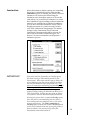
1
970922-510343-(02)
Color ID Card Printer II
Operating Instructions
© Copyright 1997 All rights reserved.
Notices
The information in this document is subject to change
without notice.
NO WARRANTY OF ANY KIND IS MADE WITH
REGARD TO THIS MATERIAL, INCLUDING, BUT
NOT LIMITED TO, THE IMPLIED WARRANTIES OF
MERCHANTABILITY AND FITNESS FOR A
PARTICULAR PURPOSE.
No liability is assumed for errors contained herein or for
incidental damages in connection with the furnishing,
performance, or use of this material.
This document contains proprietary information which
is protected by copyright. All rights are reserved. No
part of this document may be photocopied, reproduced,
or translated into another language without prior
written consent.
Patent Pending
Trademark Acknowledgements
IBM is a registered trademark of International Business
Machines Corporation. Windows is a trademark of
Microsoft Corporation. All other trademarks are the
property of their respective owners.
Printing History
Edition 1.2, #970922
© Copyright 1997 All rights reserved.
iii
For Users in the United States:
This equipment has been tested and found to comply
with the limits for a Class A digital device, pursuant to
Part 15 of the FCC Rules. These limits are designed to
provide reasonable protection against harmful
interference in a residential installation. This equipment
generates, uses, and can radiate radio frequency energy
and, if not installed and used in accordance with the
instructions, may cause harmful interference to radio
communications. However, there is no guarantee that
interference will not occur in a particular installation. If
this equipment does cause harmful interference to radio
or television reception, which can be determined by
turning the equipment off and on, the user is
encouraged to try to correct the interference by one or
more of the following measures:
■
Re-orient or relocate the receiving antenna.
■
Increase the separation between the equipment
and receiver.
■
Connect the equipment into an outlet on a circuit
different from that to which the receiver is connected.
■
Consult the dealer or an experienced radio/TV
technician for help.
Use of a shielded cable is required to comply with the
Class A limits of Part 15 of the FCC Rules.
You are cautioned that any changes or modifications not
expressly approved in this manual could void your
authority to operate and/or obtain warranty service for
this equipment.
For Users in Canada:
This digital apparatus does not exceed the Class A
limits for radio noise for digital apparatus set out on the
Radio Interference Regulations of the Canadian
Department of Communications.
Le present appareil numerique nÕemet pas de bruits
radioelectriques depassant les limites applicables aux
appareils numeriques de la class A prescrites dans le
Reglement sur le brouillage radioelectrique edicte par le
ministere des Communications du Canada.
iv
Section 1: Introduction
A. How Your Color ID Card Printer
Works .............................................................1
B. Special Features ...........................................1
Section 2: Safety Precautions ...........................3
Section 3: Getting Started
A.
B.
C.
D.
Choosing a Good Location ......................12
About Moisture Condensation ................12
Unpacking and Inspection .......................12
Identifying the Parts .................................13
Table of
Contents
Section 4: Ribbons and Cards
A.
B.
C.
D.
About Ribbons ...........................................15
Loading Ribbon into the Printer ..............17
About Cards................................................18
Loading Cards into the Printer ................20
Section 5: Card Laminating
A. About the PrinterÕs Laminator.................21
B. About Overlaminates ................................22
C. Loading the Overlaminate into
the Printer....................................................23
Section 6: Hooking Up the Printer
A. Applying Power ........................................25
B. Running the Self Test ................................25
C. Connecting the Color ID Card
Printer to Your Computer .........................26
Section 7: Installing and Using the Color ID
Card Printer Driver
A. Installing the Windows
Printer Driver .............................................28
B. Installing the 32-Bit Print Spooler for
Windows 95 ................................................30
C. Setting Up the Windows
Printer Driver .............................................32
D. Printing a Card ..........................................40
Section 8: Maintenance
A.
B.
C.
D.
E.
F.
G.
H.
I.
J.
Supplies Required .....................................41
Standard Printhead Cleaning...................42
Expanded Printhead Cleaning ................42
Cleaning the PrinterÕs Case .....................43
Cleaning the Inside of the Printer ...........43
Clearing a Card Jam ..................................43
Clearing a Ribbon Jam ..............................44
Cleaning the Card Feed Rollers ..............44
Cleaning the Drive Roller .........................45
Maintaining the Cleaning Rollers............46
v
Section 9: Mechanical Adjustments
A.
B.
C.
D.
Adjusting the Card Input Guides ............47
Adjusting the Internal Card Guide..........47
Adjusting the Card Separator Flap..........49
Adjusting the Laminator...........................51
Section 10: Troubleshooting .........................53
Section 11: Technical Specifications...........58
Appendix A: Magnetic Stripe Encoding
Module
A. Introduction ................................................59
B. Track Locations...........................................60
C. Sending Track Information .......................60
Appendix B: Interfacing Information
A. Introduction ................................................62
B. Centronics-type Parallel Interface ...........62
Index .................................................................63
vi
A. How Your
Color ID Card
Printer Works
The Color ID Card Printer utilizes dye-sublimation
printing technology to achieve its direct-to-card
photo-quality output. Dye-sublimation is a process
which uses a dye-based ribbon roll that is
partitioned by a number of consecutive color
panels. The panels are grouped in a repeating
series of four separate colors, Yellow, Magenta,
Cyan, and Black (YMCK), along the entire length
of the ribbon. The ID Card Printer always prints
the yellow panel first, followed by the magenta
panel, the cyan panel, and finally the black panel.
If applicable, the fifth clear overlay panel will
always follow the black panel.
As the ribbon and card pass simultaneously
beneath the printhead, the hundreds of thermal
elements within the printhead heat the dyes on the
ribbon. When these dyes are heated, they vaporize
and diffuse into the surface of the card. By varying
the heat intensity of each thermal element within
the printhead, it is possible for each transferred dot
of color to vary in hue, thus blending one color into
the next. The result? Continuous-tone, photorealistic color images.
The Color ID Card Printer will print from any IBMPC¨ or compatible running Windowsª 3.1x or
Windows 95. This means that you can use the
printer with virtually any software package
running under Windows without any special setup or configuration beyond the initial installation
of the specific software driver and interface cable.
Data is sent to the Color ID Card Printer in a bitmapped, rasterized format so your computer,
along with the printer driver software, will do
almost all of the complex Raster Image Processing
(ÒRIPÓ) work; therefore, the faster your computer,
the faster the image will be RIPÕd and sent to the
printer.
B. Special
Features
1
Introduction
Congratulations
on your purchase
of the Color ID
Card Printer. This
printer has been
designed to
provide you with
stunning, photoquality color
output on a
variety of
different card
sizes and
thicknesses. It
offers many
features which
easily allow you
to create full-color
photo ID cards
complete with
high resolution
graphics, text, bar
codes, and even a
clear or
holographic
overlaminate.
Your Color ID Card Printer has many distinct
advantages over other color ID card printers. Its
100 card capacity card hopper allows for automatic
card feeding which reduces the time and personnel
required to create a photo ID card. In addition, the
Color ID Card Printer offers:
■
Automatic, dual-sided printing in color or
monochrome
1
■
Simultaneous dye-sublimation/resin thermal
transfer printing capability for printing
continuous-tone photos and crisp, readable bar
codes
■
Thermal transfer film or polyester chip
overlaminate capabilities
■
Optional magnetic stripe or smart card encoding
capabilities
■
A fast print speed of just 30 seconds/full color
card
■
Fast, 32-bit print spooler for Windows 95
■
Dual-sided card cleaning system
■
Upgradable memory (2MB maximum)
■
Optional color matching software
■
Optional Ethernet network support
And best of all, operation of the printer is simple
and straight forward. Please refer to the remainder
of this manual for instructions on setting up and
printing with your new Color ID Card Printer.
2
Warnings
CAUTION!
TO PREVENT FIRE OR SHOCK HAZARD,
DO NOT EXPOSE THE UNIT TO RAIN OR
MOISTURE. TO REDUCE THE RISK OF
ELECTRIC SHOCK, DO NOT REMOVE
FRONT, TOP OR BACK PANELS. NO USERSERVICEABLE PARTS INSIDE. REFER
SERVICING TO QUALIFIED SERVICE
PERSONNEL.
Before operating the
unit, please read the
following safety
precautions carefully.
■
Operate the unit only on 110-120 VAC, 50/60 Hz.
For printers that have been shipped outside of
the United States and Canada, operate the unit
only on 220-240 VAC, 50/60 Hz. If you have any
doubt as to whether you have a unit with the
correct voltage rating for your countryÕs power
supply, DO NOT ATTEMPT TO USE THE
UNIT. Contact your dealer or the factory.
■
Stop operation immediately if any liquid or solid
object should fall into the cabinet. Unplug the
unit and have it checked by qualified service
personnel.
■
Do not disassemble the cabinet. Refer servicing
only to qualified personnel.
■
Service personnel: parts of this device may be
damaged if exposed to static electrical discharges
generated by various means, such as walking on
a carpeted floor. To avoid potential damage,
always wear an appropriate personal grounding
device, such as a wrist strap (w/ integral resistor)
connected to an ESD ground. Or, at a minimum,
make positive contact with the bare metal chassis
of the printer with your hand prior to touching
any internal electrical components.
2
Safety
Precautions
3
Sicherheitshinweise
1
VORSICHT!
ZUR VERHÜTUNG VON FEUERGEFAHR
ODER ELEKTRISCHEN SCHLÄGEN DAS
GERÄT VOR REGEN ODER FEUCHTIGKEIT
SCHÜTZEN. UM DIE GEFAHR VON
STROMSCHLÄGEN ZU VERHINDERN,
OBERE, SEITLICHE UND HINTERE
ABDECKUNG NICHT ABNEHMEN. DAS
GERÄT ENTHÄLT KEINE TEILE, DIE VOM
BENUTZER GEWARTET WERDEN KÖNNEN.
WARTUNGSARBEITEN DÜRFEN NUR VON
QUALIFIZIERTEM FACHPERSONAL
DURCHGEFÜHRT WERDEN.
Sicherheitsmaßnahmen
Machen Sie sich vor
Inbetriebnahme des
Geräts mit den
Sicherheitsmaßnahmen
gründlich vertraut.
4
■
Das GerŠt nur mit 120 V 50/60 Hz Wechselstrom
betreiben. Drucker, die au§erhalb der USA und
Kanada verwendet werden, nur mit 220/240 V
50/60 Hz Wechselstrom betreiben. Wenn Sie
nicht sicher sind, ob Ihr GerŠt mit der Spannung
des šrtlichen Stromnetzes arbeitet, DAS GERÄT
NICHT IN BETRIEB NEHMEN. Wenden Sie
sich an Ihren HŠndler oder den Hersteller des
GerŠts.
■
Den Betrieb sofort unterbrechen, wenn ein
Gegenstand in das GehŠuse gefallen oder
FlŸssigkeit eingedrungen ist. Den Netzstecker
ziehen und das GerŠt von qualifiziertem
Wartungspersonal ŸberprŸfen lassen.
■
Keine GehŠuseteile abnehmen. Wartungsarbeiten
nur von qualifiziertem Fachpersonal
durchfŸhren lassen.
Avertissements
ATTENTION!
POUR EVITER TOUT RISQUE D’INCENDIE
OU D’ELECTROCUTION, NE PAS EXPOSER
L’APPAREIL A LA PLUIE OU A L’HUMIDITE.
POUR EVITER TOUTE DECHARGE
ELECTRIQUE, NE PAS RETIRER LES
PANNEAUX AVANT, SUPERIEUR OU
ARRIERE. NE PAS TENTER DE REPARER
SOI-MEME LES PIECES A L’INTERIEUR DE
L’APPAREIL. CONFIER L’ENTRETIEN DE
L’APPAREIL A UN PERSONNEL QUALIFIE.
Avant d’utiliser
l’appareil, prière de
lire attentivement les
consignes de sécurité
suivantes.
■
Faire fonctionner lÕappareil uniquement sur
courant alternatif de 110/120 V, 50 ou 60 Hz. Les
imprimantes expŽdiŽes en-dehors des Etats-Unis
et du Canada fonctionnent uniquement sur
courant alternatif de 220/240 V, 50 or 60 Hz. En
cas de doute sur la compatibilitŽ entre la tension
nominale de lÕappareil et le courant du pays
dÕutilisation, NE PAS TENTER D’UTILISER
L’APPAREIL. Contacter le revendeur ou lÕusine.
■
Arr•ter immŽdiatement le fonctionnement si un
liquide ou un solide venait ˆ sÕinfiltrer ˆ
lÕintŽrieur de lÕarmoire. DŽbrancher lÕappareil et
le faire vŽrifier par un personnel qualifiŽ.
■
Ne pas dŽmonter lÕappareil. Confier lÕentretien
de lÕappareil ˆ un personnel qualifiŽ.
1
Consignes
de sécurité
5
Advertencias
1
¡PRECAUCION!
PARA EVITAR PELIGROS DE INCENDIO O
CHOQUE ELECTRICO, NO EXPONGA LA
UNIDAD A LA LLUVIA NI A LA HUMEDAD.
PARA REDUCIR EL RIESGO DE CHOQUE
ELECTRICO, NO QUITE LOS PANELES
FRONTALES, SUPERIORES, LATERALES NI
DE FONDO. EL INTERIOR NO TIENE PIEZAS
REPARABLES POR EL USUARIO. PARA
SERVICIO DE REPARACION Y
MANTENIMIENTO SOLICITE LA ATENCION
DE UN TECNICO DE SERVICIO
AUTORIZADO.
Precauciones
de seguridad
Antes de operar la
unidad, haga el favor
de leer detenidamente
las siguientes
precauciones de
seguridad.
6
■
Opere la unidad s—lo a 110-120 VAC, 50/60 Hz.
Para las impresoras enviadas fuera de los Estados
Unidos y Canad‡, opere la unidad s—lo a 220-240
VAC, 50/60 Hz. Si no est‡ seguro que la unidad
que tiene es compatible al voltaje de la corriente
elŽctrica de su pa’s, NO INTENTE USAR LA
UNIDAD. Llame al representante de ventas o a
la f‡brica.
■
Detenga la operaci—n inmediatamente si algœn
l’quido u objeto s—lido cayera en el armario.
Desenchufe la unidad y h‡gala revisar por un
tŽcnico de servicio autorizado.
■
No desarme el armario. Para servicio de
mantenimiento, solicite la atenci—n de un tŽcnico
autorizado.
Avvertenze
ATTENZIONE!
ONDE EVITARE IL PERICOLO DI INCENDIO
O SCOSSA ELETTRICA, NON ESPORRE
L’UNITÀ ALLA PIOGGIA OD UMIDITÀ.
EVITARE DI RIMUOVERE I PANNELLI
ANTERIORE, SUPERIORE, O POSTERIORE
PER RIDURRE IL RISCHIO DI SCOSSA
ELETTRICA. LA MANUTENZIONE DELLE
PARTI INTERNE DELL’UNITÀ NON É DI
COMPETENZA DELL’UTENTE. AI FINI
DELLA RIPARAZIONE RIVOLGERSI AL
PERSONALE DI COMPETENZA.
Prima di dare inizio al
funzionamento
dell’unità, siete
pregati di leggere
attentamente le
seguenti precauzioni
di sicurezza.
■
Negli Stati Uniti e Canada lÕunitˆ funziona solo
con alimentazione a 110-120 VAC, 50/60 Hz. Le
stampanti destinate ad altri paesi funzionano
solo con alimentazione a 220/240 VAC, 50/60 Hz.
Qualora non abbiate la certezza che il
trasformatore e la spina di cui disponete siano
quelli adeguati allÕalimentazione erogata nel
vostro paese, NON USARE L’UNITÀ. Rivolgersi
piuttosto al rivenditore o la fabbrica del luogo.
■
Arrestare immediatamento il funzionamento
dellÕunitˆ qualora si verifichi un versamento di
liquido o la caduta di un oggetto solido al suo
interno. Staccare la spina e rivolgersi al personale
di assistenza qualificato.
■
Non smontare la struttura dellÕalloggiamento. Le
riparazioni vanno effettuate solo dal personale di
competenza.
1
Precauzioni
per la
Sicurezza
7
Advertências
1
CUIDADO!
PARA EVITAR PERIGO DE CHOQUES
ELÉTRICOS OU INCÊNDIO, NÃO EXPONHA
A UNIDADE À CHUVA OU UMIDADE. PARA
REDUZIR O RISCO DE CHOQUES
ELÉTRICOS, NÃO REMOVA OS PAINÉIS
DIANTEIRO, SUPERIOR OU TRASEIRO.
NENHUMA PEÇA NO INTERIOR DESTA
UNIDADE PODE SER CONSERTADA PELO
USUÁRIO. PEÇA ASSISTÊNCIA AO PESSOAL
DE MANUTENÇÃO QUALIFICADO.
Precauções
de
Segurança
Antes de operar esta
unidade, leia
cuidadosamente as
seguintes precauções
de segurança.
8
■
Opere esta unidade somente em 110-120 VAC,
50/60 Hz. As impressoras enviadas para fora dos
Estados Unidos ou Canad‡ devem ser operadas
somente em 220-240 VAC, 50/60 Hz. Se voc• n‹o
souber se a sua unidade tem a voltagem correta
para o sistema elŽtrico do seu pais, NÃO TENTE
USAR ESTA UNIDADE. Entre em contato com
seu revendedor ou com a f‡brica.
■
Pare imediatamente a opera•‹o se qualquer
l’quido ou objeto s—lido cair no gabinete.
Desligue a unidade da tomada e leve-a ao pessoal
de manuten•‹o qualificado.
■
N‹o desmonte o gabinete. Pe•a assist•ncia
somente ao pessoal qualificado.
Chinese or Japanese to be
keylined here
9
Chinese or Japanese to be
keylined here
10
Arabic to be keylined here
11
A. Choosing a
Good Location
3
Place the unit in a location with adequate air
circulation to prevent internal heat build up.
1. Use the dimensions specified in Section 11 as a
guideline for the minimum clearances to the unit.
NOTE
Allow for adequate clearance above the unit to
accommodate the height of the unit with its covers open.
2. Do not install unit (a) near heat sources such as
radiators or air ducts, or (b) in a place subject to
direct sun-light, excessive dust, mechanical
vibration or shock.
Getting
Started
B. About
Moisture
Condensation
If the unit is brought directly from a cold to a
warm location, or is placed in a very damp room,
moisture may condense inside the unit. Should this
occur, print quality may not be optimum. Leave
the unit turned OFF in a warm, dry room for
several hours before using. This will allow the
moisture to evaporate.
C. Unpacking and
Inspection
While unpacking your printer, inspect the carton to
ensure that no damage has occurred during
shipping. Make sure that all supplied accessories
are included with your unit. The following items
should be included with your Color ID Card
Printer:
■
Printer
■
Power Cord
■
Cleaning Roller
■
Printer Driver Diskette (3.5Ó)
■
32-bit Print Spooler Software; for use in
Windows 95 only
■
Warranty Statement and Registration Card
■
This manual and other printed information
Save the carton and packing materials. They will
come in handy when transporting the unit or
shipping it for service.
12
on/cancel
laminator
LED
on-line
LED
clean/ribbon
Card
Hopper
Door
Cover
Release
Buttons
on/cancel
Button
D. Identifying
the Parts
on-line
Button
1. This illustration shows all of the control
buttons and the LED indicator lights found on the
front of the Color ID Card Printer. The laminator
light indicates the current status of the printerÕs
built-in laminator. When the light is flashing, the
laminator is either heating up or cooling down.
When the light is solid, the laminator has reached
and is maintaining its target temperature.
The on/cancel button signifies that the printer
power is ON and also serves to cancel the current
print job and reset the printer for the next print job.
This button also ejects any cards left within the
printer after a print job is canceled.
The on-line button takes the printer on and offline. The printer must have the on-line light
illuminated in order to print. When flashing, the
on-line light also serves to indicate a print error
condition. Such conditions are discussed in
Section 10 of this manual.
The clean/ribbon light illuminates when your
ribbon supply is getting low. The light will
illuminate when approximately 10-20 prints are left
on the ribbon. The clean/ribbon light also serves as
a reminder that the printer should be cleaned
during every ribbon change (about every 250
prints) according to the steps in this manualÕs
Maintenance Section.
13
2. This illustration
shows the input ports
found on the rear panel
of the printer. For
complete instructions
about each of these
features, see later
sections of this manual.
Parallel
Interface
14
Power
Switch
Power
Input
Port
A. About
Ribbons
The Color ID Card Printer has the following ribbon
types available for printing:
■
Standard Resin Black (K) ribbon with no clear
overlay panel (produces 1,000 prints)
■
A variety of Colored Resin ribbons with no clear
overlay panel (produce 1,000 prints)
■
Premium Resin Black (K) ribbon with no clear
overlay panel (produces 1,000 prints)
■
A gold Metallic Resin ribbon with no clear overlay
panel (produces 1,000 prints)
■
Dye-Sublimation Black (BO) ribbon with a clear
overlay panel (produces 500 prints)
■
Full-Color (YMCBO) ribbon with a dyesublimation black panel and a clear overlay panel
(produces 250 prints)
■
Full-Color (YMCKO) ribbon with a resin black
panel and a clear overlay panel (produces 250
prints)
■
Full-Color (YMCKOK) ribbon with 2 resin black
panels and a clear overlay panel (produces 250
prints)
■
Full-Color (YMCKK) ribbon with 2 resin black
panels and NO clear overlay panel (produces 250
prints)
4
Ribbons and
Cards
The ribbons which have a clear overlay panel (O)
will print an ID card and place a clear, protective
overlay over the cardÕs printable area. Be sure that
the Overlay option within the printer driver setup
window is selected when printing with these ribbons
unless you intend to utilize the printer's built-in
laminator. When applying the PolyGuard
overlaminate, do not apply the ribbonÕs clear overlay
panel since it will interfere with the transfer of the
overlaminate material. When applying the film
overlaminate, the ribbonÕs clear overlay should be
applied on top of the overlaminate. See Section 5-B
for further overlaminate information. See Section
7-B for instructions on enabling or disabling the
printerÕs Overlay option.
NOTE
All color or monochrome dye-sublimation cards must have
either a printed overlay or a chip or film overlaminate
applied to them. If neither of these types of protective
coatings are applied, your card's dye-sublimation image
will quickly begin to wear or fade. Cards printed solely
with monochrome resin text, bar codes, or images do not
require any type of protective overlay or overlaminate.
15
The ribbons which utilize a resin black (K), are
intended for printing bar codes onto cards which
can be read by both infra-red and visible light bar
code scanners. Bar codes printed with a dyesublimation black (B) can only be read by a visible
light bar code scanner.
The black monochrome-only resin ribbons (K) are
available in both a premium and standard quality.
The premium resin black ribbon provides
maximum durability and is ideal for applications
such as access control where cards are repeatedly
swiped through a magnetic stripe reader. The
standard resin black ribbon provides high
durability ideal for most general purpose ID card
applications.
In addition to a standard black resin ribbon, several
other standard resin ribbons are also available in a
variety of spot colors including blue, green, red,
and metallic gold. All monochrome resin ribbons
provide 1,000 prints. Bar codes printed with the
blue and green ribbons can be read by both infrared and visible light bar code scanners. Bar codes
printed with the metallic gold ribbon can only be
read by an infra-red bar code scanner. Bar codes
printed with the red ribbon are NOT readable.
The Full-Color YMCKK ribbon is intended to be
used for dual-sided printing. By supplying two
resin black panels, this ribbon lets you print fullcolor on one side and monochrome resin black on
the other, without wasting an entirely new set of
ribbon panels for the monochrome side. Since no
overlay panel is included, this ribbon must be used
in conjunction with the printerÕs overlaminate
function. If you do not wish to use the
overlaminate function, another Full-Color
YMCKOK ribbon is available which also includes a
clear overlay panel. When printing with either of
these ribbons, no overlaminate is necessary for the
monochrome resin black side.
IMPORTANT!
16
Watches, rings, bracelets, and other jewelry can damage
the printhead if accidentally bumped against it. For best
results, remove such items before installing or removing
ribbons.
B. Loading
Ribbon into the
Printer
Follow these steps to load ribbon into the Printer:
1. Remove the ribbon from its packaging. Do not
touch the colored portion of the ribbon. Oil or dirt
from your hands can impair print quality.
2. The supply end of
the ribbon is the side
with the fresh, unused
ribbon on it. The
ribbon take-up is the
other end.
Supply
Take-up
3. Open the top-right
cover of the printer by
pressing its Cover
Release Button. Allow
the cover to swing up
and open.
4. With the cover
open, place the supply
end of the ribbon in
between the two black
Ribbon Drive Hubs
located on the far righthand side of the
printerÕs interior. Make
certain that the ribbon
is fed from underneath
the ribbon roll. (Hint:
The Ribbon Drive Hub
nearest you, as you are
looking into the printer
from the front, is spring
loaded. Use the end of the
ribbon supply core to
push in this Ribbon
Drive Hub when
inserting the ribbon.)
Take-up Ribbon
Drive Hubs
Supply Ribbon
Drive Hubs
Ribbon
Sensor
17
5. Place the take-up
end of the ribbon roll
in between the two
black Ribbon Drive
Hubs located about six
inches (152mm) to the
left of the ribbon
supply Ribbon Drive
Hubs. Load the ribbon
take-up end of the
ribbon just as you
loaded the ribbon
supply end in step 4.
When loaded properly,
the ribbon should feed
underneath both ends
of the ribbon roll.
Take-up Roll
Supply Roll
Cleaning Roller Assembly
6. Close the cover. When you start to print, the
Ribbon Drive Hubs will automatically engage the
notches on both cores of the ribbon roll.
IMPORTANT!
Do not reverse the ribbon. Damage may occur to the
thermal printhead!
C. About Cards
The Color ID Card Printer accepts a variety of
different card sizes and thicknesses and will print
to any card with a clean, level, polished PVC
surface (see Section 11 for accepted card size
specifications). The printer can also print onto
smart cards, but one must be careful not to print or
place a clear overlay over the area containing the
actual IC chip. Printing over this area could
damage both the IC chip and the printerÕs
printhead. To avoid printing over this area, select
the Smart Card option from the printer driver
setup (see Section 7-B for printer driver
information).
Although the Color ID Card Printer is equipped
with a card cleaning roller, it is very important to
always print onto cards specifically designed for
direct-to-card dye-sublimation printing. Such cards
must have a polished PVC surface free of
fingerprints, dust, and any other types of
embedded contaminants. In addition, these cards
must have a completely smooth and level surface
in order for the printer to achieve consistent color
coverage (many brands of Proximity cards have an
uneven surface which can inhibit consistent color
transfer). For information on cards suitable for
direct-to-card dye-sublimation printing, contact
your authorized Color ID Card Printer dealer or
the printer manufacturer.
18
Never run cards with a contaminated, dull, or
uneven surface through the printer. Printing onto
such cards will ultimately lead to poor print
quality and will greatly reduce the life of your
printhead. In addition, always store your card
stock in its original packaging or in a clean, dustfree environment. Do not print onto cards which
have been dropped or soiled. Printheads damaged
by contaminated or poor quality cards will
automatically void the printhead’s factory
warranty.
NOTES
1. Some card stocks, particularly 10 mil card stocks, are
surfaced with a thin coating of a talcum based lubricant.
This lubricant is intended to keep the cards from
sticking to one another, however, the dusty nature of the
lubricant will greatly inhibit print quality and may even
damage the printer. Do not print onto these types of
cards.
2. Avoid using card stock which has a signature pad on
the back side of the card. A signature pad will often
leave a residue on the top of the card stacked beneath it.
This residue will discolor the card’s surface when
printed. If a card signature is required, use cards with a
matte finish on the reverse side and a polished PVC
finish on top. Signatures can be applied to the matte
finished side with a permanent ink pen after printing.
3. If printing onto cards with a pre-punched slot, do not
print over the area of the card with the punched slot.
Printing over this uneven area could damage the
printhead. To avoid this area when printing in portrait
orientation, select the Punch card size option from
within your printer driver setup (see Section 7-B for
printer driver information). When selected, this option
allows your printer to print up to but not over the
punched area of the card. This option does not apply to
pre-punched cards intended to be printed and worn in
landscape orientation. If you need to print over the
entire area of the card, punch the slot after the card has
printed.
19
D. Loading Cards
into the Printer
The Color ID Card Printer will hold a maximum of
100 cards (based on a standard CR-80 card size) in
its Card Hopper. The Printer automatically feeds
each card and adjusts to each cardÕs particular size
and thickness. Significantly larger or thicker cards,
however, may require slight printer adjustments
for consistent printing. See Section 9 for details on
such adjustments. To load the cards into the
printer, refer to the following steps:
1. Remove a stack of 100 or fewer cards from the
card packaging. Do not touch the area of the card
where you intend to print. Oil or dirt from your
hands can impair print quality.
2. Open the Card Hopper Door located on the
right-hand side of the printerÕs exterior by
grasping the top of the door and pulling down.
Allow the door to swing completely open.
3. Insert the stack of cards into the printer by
depressing the spring loaded Card Input Tray and
placing the cards between the Card Input Guides
(see Section 9 for further Card Input Guide
information). Always load cards with the top or
primary print side facing up. If inserting cards
with a magnetic stripe, be sure that the magnetic
stripe is positioned downward and that the stripe
is oriented toward the rear of the printer. If
inserting smart cards or cards with a pre-punched
slot, be sure the smart card chip is positioned
upward and that the chip or slotted end of the card
is inserted first.
4.
Once the cards
have been inserted,
remove the top card
and throw it away if
you suspect it has been
contaminated with oil
from your fingertips.
Close the Card Hopper
Door. The cards will
automatically feed off
the top of the stack.
Card Input Tray
Card Input Guides
Card Input Hopper Door
NOTE
20
The printer’s 100 card capacity is figured using a
standard CR-80 3.375”L x 2.125”W x .030” (85.6mmL
x 54.0mmW) card size. Please be aware of this when
inserting cards of varying thicknesses.
A. About the
Printer’s
Laminator
In addition to printing and applying the standard
clear overlay included on the Color ID Card
PrinterÕs various ribbons, the printer also provides
a built-in lamination system for applying a more
secure, tamper-resistant overlaminate. This built-in
laminator is controlled by both the printer itself and
the printerÕs software driver.
Upon initial power up of the printer, you will
notice that the Laminator LED indicator light on
the front of the printer will flash. This indicates that
the laminator is heating up to its preset, or default
laminating temperature of approximately 300¡ F
(150¡ C). This heating process will generally take
about 5 minutes before the laminator is heated to
the default temperature. Once the laminator
reaches its default temperature, the Laminator LED
light will stop flashing and will remain solid. The
Laminator LED light will flash only when the
laminator is heating up or cooling down to the
prescribed temperature.
5
Card
Laminating
If you wish to change the temperature of the
laminator, you can adjust its temperature through
the Lamination controls within the printer driver
setup window (see Section 7-B). Once adjusted, the
new temperature settings will be sent down with
the next print job along with the rest of the printer
driver information. Before printing begins, the
Laminator light will flash and the laminator will
automatically adjust itself to the new temperature
setting. This new temperature setting will remain
programmed within the printer until it is once
again changed within the printer driver or until the
printer is turned OFF. Whenever the printer is
turned OFF, the laminator will automatically reset
itself and return to its default temperature the next
time the printer is powered ON. Pressing the
on/cancel button serves this same purpose in that it
will also reset the laminator to its default
temperature. The temperature setting within the
printer driver, however, will stay the same until
you change it.
CAUTION!
!
THE PRINTER’S LAMINATION ROLLER CAN
REACH TEMPERATURES EXCEEDING 350° F
(175° C). USE EXTREME CAUTION WHEN
OPERATING THE LAMINATOR. NEVER TOUCH
THE LAMINATION ROLLER UNLESS THE
PRINTER POWER HAS BEEN TURNED OFF FOR
AT LEAST 20-30 MINUTES!
21
B. About
Overlaminates
The Color ID Card PrinterÕs internal lamination
system allows you to choose between either a
thermal transfer film overlaminate or a polyester
chip overlaminate called PolyGuardª. These two
unique overlaminates are available in two specific
designs. The film overlaminate is available as
simply a clear material or with a generic,
preprinted holographic-type design and is
approximately 2 microns thick.
PolyGuard, which is approximately 1 mil (.001Ó)
thick, is available in these same designs but
provides for greater durability than the thermal
film overlaminate. PolyGuard should always be
used if you need ID cards with the highest degree
of durability and security.
If you require custom thermal transfer film or
PolyGuard overlaminate designs, please contact
your reseller or the printer manufacturer for more
information.
IMPORTANT!
22
If using the thermal transfer film overlaminate, you must
use it in conjunction with a ribbon which provides a clear
overlay panel. When used with this type of ribbon, the
printer will apply the clear overlay panel of the ribbon
over the film lamination layer of a printed card. This
process is required for maximizing card durability when
laminating with the thermal transfer film material. The
ribbon types which do not provide an overlay panel or
support overlay printing are Monochrome Resin and 5
Color Resin black. Avoid using these types of ribbons
in conjunction with the thermal transfer film material.
These ribbon types are ideal, however, when laminating
with PolyGuard.
C. Loading the
Overlaminate
into the Printer
The loading process for both the thermal transfer
film and the PolyGuard overlaminate material is
the same. Refer to the following steps to load either
type of overlaminate into the Printer.
CAUTION!
DO NOT TOUCH THE METAL LAMINATION
SHIELD OR THE LAMINATION ROLLER WHEN
LOADING OVERLAMINATE. YOU WILL BURN
YOURSELF!
!
1. Remove the
overlaminate from its
packaging.
2. The supply end of
the overlaminate roll is
the side containing the
fresh, unused portion
of the overlaminate.
The take-up end is the
other side.
Supply
Take-up
3. Open the top-left
cover of the printer by
pressing its Cover
Release Button. Allow
the cover to swing up
and open.
4. With the cover
open, place the supply
end of the
overlaminate roll in
between the two black
Lamination Drive
Hubs located just to the
left of the printerÕs
card flipping
mechanism. Make
certain that the
overlaminate material
is fed from underneath
the roll. (Hint: The
Lamination Drive Hub
nearest you, as you are
looking into the printer
from the front, is spring
loaded. Use the end of the
roll’s supply core to push
in this hub when
inserting the
overlaminate roll.)
Take-up
Lamination
Drive Hubs
Supply
Lamination
Drive Hubs
Card Flipping
Mechanism
23
5. Place the take-up
end of the roll in
between the two black
Lamination Drive
Hubs located on the
far left-hand side of
the printerÕs interior.
Load the take-up end
of the roll just as you
loaded the supply end
in step 4. When loaded
properly, the
overlaminate material
should feed
underneath both ends
of the overlaminate
roll.
Supply Roll
Take-up Roll
6. Close the cover. When you start to print, the
Lamination Drive Hubs will automatically engage
the notches on both cores of the overlaminate roll.
IMPORTANT!
24
Do not reverse the overlaminate roll. Damage may occur
to the lamination roller!
A. Applying
Power
1. Locate the power
cord supplied with
your printer.
2. With the printerÕs
power switch turned
OFF, place one end of
the power cord into the
power port on the rear
panel of the printer.
ON
I
O
AC POWER
PARALLEL
OFF
SW1
6
Hooking Up
the Printer
3. Place the other end
of the power cord into
an available wall
outlet.
4. Once the power
cord is connected, turn
the power switch
located on the rear
panel of the printer to
its ON position.
B. Running the
Self Test
A self test should now be performed to check for
proper operation of the printer. The standard self
test function requires only that a full-color ribbon
and at least one card is installed. The standard self
test function prints onto both sides of a card but
does not utilize any of the printerÕs overlay
capabilities. If printing with a full-color ribbon
with a resin black panel, most rectangles on the
back side of the self test card will appear as solid
black. A sample of the self test pattern is shown on
the following page.
1. If power is ON, turn it OFF now by pressing
the on/cancel button. The LED indicator lights
should no longer be illuminated. Verify that a fullcolor ribbon is installed and that cards are properly
loaded.
2.
3.
Press and hold the on-line button.
While holding the on-line button down, turn
the printer power back ON by quickly pressing
and releasing the on/cancel button.
4. Release the on-line button. The gray scale self
test will begin printing approximately 5 seconds
after the on-line button has been released.
25
v1.x.x
Self Test Example: (Actual size)
C. Connecting
the Color ID
Card Printer to
Your Computer
The Color ID Card Printer is designed to be used
with nearly any IBM-PC or compatible running
Windows 3.1x or Windows 95. A minimum of a
486 DX class computer with 4MB RAM or higher is
required. For best performance, a Pentiumª class
computer with 8 MB RAM or higher is
recommended.
The printer is equipped with an ECP-compatible,
high-speed Centronics parallel port. This port is
the means through which the printer receives data
from your computer. To connect the printer to
your computer, obtain a shielded, bi-directional
parallel cable and refer to the following steps:
1. Connect the
Centronics-type
parallel side to the
printer. Snap the
fastening clips into
place.
26
2. Connect the other
side to the back of your
PC at the PARALLEL
connector.
3. The printer must have its on-line light
illuminated to receive data. If the light is not ON,
press the on-line button.
4. If the on-line light is flashing, check for a card
mis-feed or jam and correct according to Section 8.
Press the on-line button to resume operation.
27
7
Installing
and Using
the Color ID
Card Printer
Driver
A. Installing the
Windows Printer
Driver
The Color ID Card Printer can be used with
virtually any Microsoft Windows 3.1x or Windows
95 software application program. Before printing,
you must tell the application that youÕre using the
Color ID Card Printer. This is accomplished the
first time you use the printer by installing in
Windows what is called a Òprinter driver.Ó The
printer driver is simply a diskette with software on
it that gives the printer the proper commands it
needs in order to print. After youÕve installed the
driver, put the driver diskette away in a safe place
for possible future use.
NOTE
This section of the Operator’s Manual assumes that you
are already familiar with Windows and know how it
operates. If you are not yet familiar with Windows,
consult the appropriate Microsoft documentation to
become familiar with the basics of Windows before
proceeding.
Windows 95
To install the printer driver into Windows 95, refer
to the following:
1. Insert the printer driver diskette into your
computerÕs disk drive.
2.
Click the Start button, point to Settings, and
select Printers.
3.
28
Double-click on the Add Printer icon.
4. Follow the on-screen instructions to complete
installation. When prompted, do not have
Windows print a test print, since you most likely
performed a printer self test in Section 6. Once
installed, the ÒColor ID Card IIÓ printer icon will
appear in the Printers folder.
NOTE
Before installing updated printer driver versions,
always delete the existing printer driver version from
your system. To do this, simply select the printer driver
from within the Printers folder, and press the Delete
key.
Windows 3.1x
To install the printer driver into Windows 3.1x,
refer to the following:
1. After starting Windows, go to the Main
program group and select Control Panel.
2.
3.
From the Control Panel, select Printers.
4.
5.
Select the Add>> button.
6.
7.
Select the Install button.
Select Use Print Manager from the bottom left
of the Printers window.
Highlight the Install Unlisted or Updated
Printer option from List of Printers.
Insert the supplied Printer Driver diskette into
your computerÕs disk drive. If you insert the
diskette in a drive other than the A: drive
displayed in the Install Driver dialog box, you
must change the drive designation. Select the OK
button.
8. ÒColor ID Card IIÓ should now be listed in the
Add Unlisted or Updated Printer dialog box.
Select the OK button. Your PCÕs disk drive will
now load the printer driver. Depending upon
your computer, loading will take about 10 to 20
seconds.
9.
Select the Set As Default Printer button in the
Printers window. The Color ID Card Printer has
now been selected as your default (main) printer.
If you wish to use another printer later, you must
de-select the Color ID Card Printer and switch
back to the other printerÕs driver.
29
10. Finally, select the Connect button. Check that
the box called Fast Printing Direct to Port is
selected. Although this option is not necessary, it
helps optimize printer driver speed and
performance. Select OK to exit the Connect
window. Select Close to exit the Printers window.
B. Installing the
32-Bit Print
Spooler for
Windows 95
Your Color ID Card Printer ships with a print
utility program called the 32-Bit Print Spooler. This
print spooler is for use only with Windows 95.
Once installed, the print spooler is able to process
your print jobs and send them to the printer at
consistently faster speeds than if sending print jobs
through the Windows 95 print spooler. This is
especially true if printing with an ECP compatible
parallel port or if printing off a network. The 32-Bit
Print Spooler is ideal for printing a large number of
consecutive ID cards, for printing larger file
formats (1 MB of more), or if printing on a
somewhat slower computer.
The 32-Bit Print Spooler installs just like any other
standard Windows application program. To install
the 32-Bit Print Spooler, refer to the following:
1. Insert the 32-Bit Print Spooler diskette into your
computerÕs disk drive.
2.
Click the Start button, point to Settings, and
select Control Panel.
3.
Double-click on the Add/Remove Programs
icon.
30
4. Follow the on-screen instructions to complete
installation. When installed, the 32-Bit Print
Spooler will appear in the Programs group of the
Start menu.
NOTE
Before installing updated 32-Bit Print Spooler versions,
always uninstall the existing print spooler version from
your system. To do this, simply select 32-Bit Print
Spooler from the list of programs in the Add/Remove
Programs Properties window and click on the
Add/Remove button.
To print with the 32-Bit Print Spooler, you must
select the Fast 32-bit Spooler option from within
the printer driver setup window as described in
section C. When this option is selected, the print
spooler will automatically open and close with the
start and finish of each print job.
NOTE
You can also manually open the 32-Bit Print Spooler
simply by selecting its icon from the Programs group of
the Start menu.
When the 32-Bit Print Spooler is running, its icon
will appear in the Windows 95 Task Bar. During a
print job, it is sometimes helpful to click on this
icon to bring the 32-Bit Print Spooler status
window to the foreground of your application.
This window provides a number of details about
the print jobs being sent to the Color ID Card
Printer.
The Current Job tab tells you the name and size of
the file printing, the progress of the overall print
job, as well as the total number of copies left to
print. It also provides buttons which allow you to
pause or cancel the print job at any time during the
printing process.
The Settings tab tells you the port and printer to
which you are printing and also allows you to
configure the timeout setting. In most instances,
the settings under this tab rarely need to be
changed.
31
The Job Queue tab appears only when a print job is
being sent to the printer. This tab tells you the
name and status of each job in the queue and shows
you the order in which the jobs will print if you
have sent multiple jobs to the printer. A control
button is also provided which allows you to delete
every job listed in the queue. To delete the job
currently being printed, simply select the Cancel
Print button under the Current Job tab.
C. Setting Up
the Windows
Printer Driver
Once the printer driver has been successfully
installed, you will need to set the driver up for the
particular card size and type of ribbon you have
installed in the printer. There are also several
additional options that can be selected. Use the
following steps to select the appropriate printer
driver settings:
1. If using Windows 3.1x, go back to the Control
Panel and the Printers group using steps 1 and 2 on
pages 27 and 28. If using Windows 95, Click the
Start button, point to Settings, and select Printers.
Then, click on the Color ID Card II icon with the
right mouse button and select Properties. The
Properties window will appear.
2. In Windows 3.1x, select the Setup button. In
Windows 95, click on the Details tab of the
Properties window and select the Setup button.
NOTE
3. The Color ID Card II
Printer screen appears.
Change the options as
follows:
32
Some applications allow you to change these same
printer driver options from their “Print” and/or “Printer
Setup” screens. This means that you don’t have to go
back to the main printer setup window each time you
want to change a setting or option in the printer driver.
These applications will usually give you the same choices
and options, but in a slightly altered format.
Card Size
Click on the Card Size down arrow. A list of card
size selections will appear. The Std CR-80 and
Oversize selections allow you to print and overlay
the entire printable area of a standard or oversized
card. Keep in mind that all card sizes have a slight
non-printable margin around the entire edge of the
card. The Smart Card, Magstripe, and Punch
Offset selections allow you to print and overlay
only within the given card areas. The Smart Chip
selection allows you to print and overlay anywhere
on a card except over the immediate location of a
standard smart card chip. These selections prevent
you from printing over or damaging the area of the
card containing the magnetic stripe, IC chip, or
punched slot.
The Dual Side: CR-80/Magstripe selection should
be selected only when printing onto both sides of a
standard CR-80 card which has a magnetic stripe
on the back. This option allows you to print and
overlay the entire front of a card while applying an
overlay only onto the area opposite the magnetic
stripe on the back of a card. This prevents the
magnetic stripe from being damaged. Although
this options prevents the overlay from being
applied to the magnetic stripe area of a card, it is
still possible to print text or images over the
magnetic stripe. Therefore, when designing the
back of your card format, you must be careful not
to place any printable objects over the magnetic
stripe area of the card. Note that the Duplex
Printing option must be selected to print onto both
sides of a card.
The JIS II Magstripe Side option should be
selected only when printing onto cards with a
Japanese standard JIS II magnetic stripe. Select the
card size option thatÕs appropriate for the type of
card you are using (see Section 4-C for important
card stock information).
Ribbon Type
Click on the Ribbon Type down arrow. A list of
ribbon selections will appear. Select the ribbon type
option thatÕs appropriate for the type of ribbon you
are using (see Section 4-A for further ribbon
information).
Color Matching
Click on the Color Matching down arrow and
select the appropriate color matching option. Select
None if you are more interested in print speed
rather than print color, if you have already color
corrected your image for printing, or if you are
using some other third party color matching
software.
33
Select Algebraic if you would like the printer
driver to make very simple, yet fast, color balance
adjustments. This option gives you more natural
looking images without actually utilizing any
specific color matching software and without
slowing down the processing speed of the printer
driver. When selected, this color matching method
can be customized by selecting the Controls button.
The FargoColor™ option is only available when the
printerÕs optional color matching software upgrade
has been installed. Select this option to enable color
matching profiles written specifically for your
printer. The FargoColor option automatically
adjusts the color of your image according to
preconfigured printer profiles and default system
profiles. This results in a very precise color match
compliant with ICC standards. Please note that
since the FargoColor option is intended to match
photographic color hues as closely as possible, you
may notice that some colors may appear slightly
muted when printing simple spot colors.
34
Dither Mode
This option only effects objects printed with a
monochrome resin ribbon type or those objects
printed with the monochrome resin panel of a fullcolor ribbon. Click on the Dither Mode down
arrow and select the appropriate dither method
according to the type of image you are printing.
Overlay
This option is only applicable if you are using a
ribbon with a clear overlay panel. If using such a
ribbon, select this option to enable the printer to
place a clear overlay over the entire printable area
of the given card size. Do not select this option,
however, if you are not using a ribbon with a clear
overlay panel or if you intend to apply a separate
overlaminate to the card. Remember that all dyesublimation prints must have either the ribbonÕs
overlay or a separate overlaminate applied to them
to prevent premature wear or fading.
K Panel Graphics
In most application programs, when printing with
a Full-Color YMCKO ribbon, the Color ID Card
Printer driver prints all bitmapped images with the
ribbonÕs yellow, magenta, and cyan color panels
(YMC). Any black contained in these bitmapped
images is printed by combining equal amounts of
yellow, magenta, and cyan. This type of black is
called a ÒcompositeÓ black. The resin black (K)
panel of the ribbon is only used when printing
TrueType black text and TrueType bar codes.
The printer driver distinguishes between text and
image objects in order for TrueType black text and
bar codes to always be printed with a true resin
black. Resin black is essential when printing bar
codes, since only resin black bar codes can be read
by both infra-red and visible light bar code
scanners. Composite or dye-sublimation black bar
codes can only be read by visible light bar code
scanners.
In some cases, however, this print method may not
be acceptable. If, for example, you are printing bar
codes which are not TrueType bar codes but rather
bitmapped bar codes, such bar codes will be
printed as a composite black (i.e., with the YMC
panels only). In addition, when printing from
certain application programs, the printer driver is
also forced to print all objects, even black text or
bar codes, with the yellow, magenta, and cyan
color panels. This happens because some
application programs interpret both text and image
objects as bitmapped images.
If your particular application program does not
differentiate between TrueType text and image
objects or if you are printing bitmapped bar codes,
select the K Panel Graphics print option. This
option forces the printer driver to print all of the
black within text, bar codes, or bitmapped images
with all four of the ribbon’s YMCK panels.
K Panel Only
This option is only active when the K Panel
Graphics option is selected. When the K Panel
Only option is selected, all of the black within text,
bar codes, or bitmapped images will be printed
only with the ribbonÕs resin black (K) panel (i.e.,
without the YMC composite black underneath).
Selecting this option increases the precision of
printed bitmapped bar codes, thereby assuring
greater accuracy when read by a bar code scanner.
Split Ribbon
Print
Select this option to automatically print full-color
on the front of a card and monochrome on the back
of a card using a standard Full-Color YMCKO
ribbon. This option allows the printer to print the
front of a card with the ribbonÕs yellow, magenta,
and cyan (YMC) panels and the back of a card with
the ribbonÕs black (K) panel. The ribbonÕs clear
overlay is applied last to the cardÕs front side.
Selecting this option provides the most economical
means of printing a dual-sided card with overlay,
since you avoid wasting an entirely new set of
ribbon panels just to print the monochrome back
side. Note that the Duplex Printing option is
automatically enabled when this option is selected.
35
Back Side Only
Select this option to print the back side of a card
only. This option allows you to conveniently print
the back side of preprinted cards which also must
have their magnetic stripe or smart card chip
encoded. Be sure to load cards in the usual fashion
as described in Section 4-D. Note that when this
option is selected, the Duplex Printing option is
automatically disabled.
Rotate 180º
This option allows you to rotate your image 180¼
when printed. Select this option if you wish to
change the position of your image in relation to the
set location of a cardÕs magnetic stripe.
Mag Encode
Only
Select this option if you wish to send only the
magnetic track data of a card format to the printer.
This unique feature enables the Color ID Card
Printer to function solely as a magnetic stripe
encoder so you can easily encode or re-encode
preprinted cards without wasting additional time,
effort, or printing supplies.
Write Direct
to Port
Selecting this option provides the fastest print
processing when printing through a standard
parallel port which is not ECP compatible or when
printing exclusively from Windows 3.1x. When
selected, this option allows the printer driver to
bypass the Windows 3.1x Print Manager or the
print spooler of Windows 95 and to send all print
data directly to the Color ID Card Printer. This
option devotes all of your system resources to the
current print job, thereby increasing overall print
speed. When the print job is finished, your system
resources will again be released and devoted to the
normal function of your on-screen applications.
Depending upon the processing speed and brand
of your computer, you may or may not need to
select this option when printing with the Color ID
Card Printer. For most computers with a non-ECP
compatible parallel port, selecting this option will
enhance the speed of the rasterizing and printing
process. In this case, the Write Direct to Port option
should be selected. For some computers, however,
this option may either not be supported by the
particular brand of PC or simply may not be
necessary due to the PCÕs fast processing speed. In
this case, the Write Direct to Port option should
not be selected.
NOTE
36
This option will not function properly if using any type
of external printer buffer. When using a printer buffer,
all print jobs should be sent through the system print
spooler or through the Color ID Card Printer’s 32-Bit
Print Spooler for Windows 95.
Fast 32-bit
Spooler
Select this option for consistently faster print
processing. This option is only selectable if
operating under Windows 95 and if the included
32-Bit Print Spooler software has been installed.
When selected, this option allows the printer
driver to send all print jobs to the Color ID Card
PrinterÕs 32-Bit Print Spooler rather than to the
Windows 95 print spooler. See section B for
complete details on the 32-Bit Print Spooler. This
option and the 32-Bit Print Spooler software will
not function in Windows 3.1x.
Duplex Printing
Select this option to automatically print on both the
front and back side of a card. This option can be
selected in conjunction with any application
program which supports a multiple page
document. In other words, your program must be
able to send down two or more separate pages to
be printed within the same document.
For example, if you would like to print a full color
ID format on the front of your card and
monochrome text or bar codes on the back, you
would simply create the full color front side of the
card on page 1 of your document and the
monochrome back side on page 2. The printer
driver will always place all odd numbered pages
on the front side of the card and all even numbered
pages on the back side.
Orientation
Select either Portrait or Landscape. Selecting
Portrait causes the card to print in a vertical
orientation. Selecting Landscape causes the card to
print in a horizontal orientation. An icon
illustrating a printed card helps represent the
difference between the two.
37
38
Controls
Select this button to display options for controlling
a printed cardÕs Brightness, Contrast, or Gamma, as
well as for controlling the cardÕs individual color
balance for Yellow, Magenta, and Cyan. Select the
Default button to return all control options to the
original settings. When the Algebraic color
matching option is selected, all control options will
display and can be adjusted. When the None or
FargoColor color matching options are selected,
only the Brightness (Heat) option will display.
Magnetics
When magnetically encoding a card with the Color
ID Card Printer, the ISO standards for magnetic
encoding will automatically be used. These
standard settings will suffice for most encoding
applications and rarely need to be modified. If
modification is necessary, however, please see
Appendix A for more information on the printerÕs
magnetic encoding process.
Lamination
Select this button to display options for controlling
the printerÕs lamination process. When the No
Lamination option is selected, the printerÕs built-in
laminator will not be used. When using the
laminator, select from these options to choose the
card side(s) you would like to laminate or to select
the Lamination Type according to the overlaminate
material you currently have installed. In addition,
you can also select the Lamination Dwell Time or
through-put speed of a card in seconds/inch as
well as the Lamination Temperature. The default
settings for the Lamination Dwell Time and
Lamination Temperature should be accurate for
most card stocks and overlaminate types. See
Section 5 for more information on the printerÕs
lamination process.
IMPORTANT!
If you select the Film Lamination w/ Overlay option,
you must be using a ribbon which provides a clear
overlay panel. When used with this type of ribbon, the
printer will apply the clear overlay panel of the ribbon
over the film lamination layer of a printed card. This
process is required for maximizing card durability when
laminating with the thermal transfer film material. The
ribbon types which do not provide an overlay panel or
support overlay printing are Monochrome Resin and 5
Color, Resin Black. Avoid using these types of ribbons
in conjunction with the thermal transfer film material.
Selecting the printer driver’s standard Overlay option
forces the printer to automatically place the ribbon’s
clear overlay panel onto whichever side or sides of the
card you are printing. The Film Lamination w/
Overlay option overrides the standard Overlay option
for the card’s laminated side only, forcing the printer to
place the ribbon’s clear overlay on top of the film
overlaminate rather than beneath it.
39
For example, if you are printing onto both sides of a card
and you have both the Overlay and the Film
Lamination w/ Overlay options selected, the ribbon’s
clear overlay panel will be placed on top of the film
laminated side as well as over the printed reverse side.
As a rule, do not select the standard Overlay option in
conjunction with the Film Lamination w/ Overlay
option if you do not wish to place the ribbon’s clear
overlay onto the printed, non-laminated back side of a
card.
4.
After your selections have been made, close out
of the printer setup window. You are now ready to
go to an application program and print. All printer
driver options selected will stay the same until you
change them.
D. Printing a Card
Now that youÕve set up the printer, loaded media,
and installed the printer driver, youÕre ready to
print an ID card. Follow these steps to print your
first card:
1. Go to the Windows application program in
which you will be creating your cards and open or
create a card format.
2. Once you are ready to print, select Print Setup
(or the equivalent) from the programÕs File menu to
verify that the printer driver settings are correct for
your card design. Remember to select the proper
card size and ribbon type and, if applicable, to
verify that the proper magnetic and/or lamination
settings are selected. After youÕve properly
configured the driver, select the Print button from
the applicationÕs Print screen.
3. The Color ID Card PrinterÕs RIP (raster image
processing) begins. The image processing time will
vary depending upon the complexity of the image
and the processing speed of your computer.
4. After the image is processed and sent to the
printer, the printer will draw in a card and print
the first color (yellow), followed by the remaining
colors (magenta, cyan, and black). If using a ribbon
with a clear overlay, the clear overlay panel will
print immediately after the last color panel. If
printing onto the back side of a card, encoding, or
applying an overlaminate, the printer will finish
these functions last and then eject the card.
5. If everything looks good, youÕve successfully
completed set-up, initial testing, and printing with
your Color ID Card Printer.
40
Drive
Rollers
Cleaning
Roller
Assembly
Supply Ribbon
Drive Hubs
8
Maintenance
Printhead
A. Supplies
Required
Printhead Assembly
For the maintenance procedures outlined in this
section, you will need the following items:
■ Isopropyl alcohol
■ Acetone
■ Standard clear adhesive tape or masking tape
■ Soft, lint-free cloth
Or, to make these maintenance procedures more
convenient, a Printer Cleaning Kit is available from
your reseller or from the printer manufacturer. This
optional kit includes the following:
■ Printhead Cleaning Pens pre-moistened with
99.99% isopropyl alcohol for cleaning your
printerÕs printhead.
■ Cleaning Cards with an adhesive backing for
automatically cleaning your printerÕs gray card
feed rollers and cleaning rollers.
■ Cleaning Pads pre-moistened with 99.99%
isopropyl alcohol for cleaning your printerÕs
drive roller and general inside area.
IMPORTANT!
Your Color ID
Card Printer is
built to require a
minimum of
maintenance.
Nevertheless,
there are a few
procedures you
can perform on a
regular basis or
as needed to
ensure the best
possible
performance. Use
the illustration at
the top of this
page to locate the
items discussed
within this
section.
1. Never use a sharp tool or abrasive object of any kind
to clean the printhead. You will damage the printhead!
2. Watches, rings, bracelets, and other jewelry can
damage the printhead if accidentally bumped against it.
For best results, remove such items before touching any
internal components of printer.
3. Internal components of the printer, such as the
printhead, may be damaged if exposed to static electrical
discharges generated by various means, such as walking
on a carpeted floor. To avoid potential damage, always
wear an appropriate personal grounding device, such as
41
a wrist strap (with integral resistor) connected to an
ESD ground. Or, at a minimum, make positive contact
with the bare metal chassis of the printer with your hand
prior to touching any internal electrical components.
B. Standard
Printhead
Cleaning
This procedure should be performed if you notice a
streak on the card where color was not transferred.
This procedure should also be performed during
every ribbon change or after every 250 prints in
order to maintain consistent print quality. The
printhead is located near the center of the opened
top cover assembly.
1. Open the printerÕs top-right cover by pressing
its Cover Release Button.
2. If you observe dust and/or other particles
laying on the top surface of the ribbon, manually
roll it up into the take-up roll. Occasionally, dust
may settle on the top surface of the ribbon and
cause print quality problems.
3. Use a Printhead Cleaning Pen from the Printer
Cleaning Kit or a soft, lint-free cloth slightly
moistened with isopropyl alcohol to wipe dust and
other accumulated particles off the surface of the
printhead. If using a cloth, be extremely careful not
to use too much alcohol. It must not be allowed to
drip into the printer!
4. Once the printhead is completely dry, shut the
cover. If a streak persists, perform the steps in
section C.
C. Expanded
Printhead
Cleaning
Perform if you have a streak on the printed output
that canÕt be solved by the Standard Printhead
Cleaning procedure. To maintain your printerÕs
high quality of printing, this procedure should also
be performed approximately every 2,500 prints as
part of the printerÕs general maintenance program.
1. Open the printerÕs top-right cover by pressing
its Cover Release Button.
2. Use a soft, lint-free cloth slightly moistened
with acetone to wipe off the surface of the
printhead. Be extremely careful not to use too much
acetone. It must not be allowed to drip into the
printer!
CAUTION!
42
ACETONE IS A VERY POWERFUL SOLVENT. DO
NOT APPLY ACETONE TO ANY OTHER AREA OF
THE PRINTER, SINCE IT WILL DESTROY THE
FINISH OF PAINT, RUBBER, AND PLASTIC.
3. Allow the printhead to thoroughly dry before
closing the cover.
4. Shut the cover. If a streak persists, contact your
dealer or the technical support number listed on
the insert in this manual for further assistance.
D. Cleaning the
Printer’s Case
Your Color ID Card Printer has a durable casing
that should retain its luster and appearance for
many years. Clean it only with a soft cloth slightly
dampened with water or a mild soap. Do not use
excess water or cleaning solvents of any kind.
Never spray the cabinet with a cleaner. Rather,
spray the cloth first, then wipe down the printer.
E. Cleaning the
Inside of the
Printer
As you use your printer, dust and other foreign
particles may accumulate inside the printerÕs case.
These particles are attracted to the underside of the
ribbon by static produced during printing and can
cause voids on the printed image. Periodically, use
the following procedure to remove dust and other
foreign particles:
1.
2.
Open both of the printerÕs top covers.
Remove the ribbon from the printer and set it
on the ends of its ribbon cores.
3. Remove any overlaminate which may be
installed in the printer.
4. Use a Cleaning Pad from the Printer Cleaning
Kit or a soft, lint-free cloth slightly moistened with
isopropyl alcohol to wipe out all visible areas
inside the printer. Remove any debris that may be
inside. Be extremely careful not to let any alcohol
drip inside the printer!
5. Once the cleaned areas are completely dry and
free of foreign debris, re-install the ribbon and close
the cover.
F. Clearing a
Card Jam
If a card becomes jammed inside the printer for
some reason, remove it through the following
steps:
1. Leave the power ON and open either or both of
the printerÕs top covers.
2. Remove the ribbon and/or overlaminate if
needed.
3. Press the on/cancel button to advance the card.
Press the on-line button to reverse the card.
4. Close the cover. Press the on/cancel button to
clear its input buffer memory. Select the Cancel
button (or equivalent) in your application program
and start the print over again.
43
G. Clearing a
Ribbon Jam
If the ribbon or overlaminate becomes jammed in
the drive roller (visible when you open the printerÕs
top covers), use the following procedure to correct
the problem:
1. Leave the power ON and open either or both of
the printerÕs top covers.
2. Remove the Take-Up core (the side with used
ribbon or overlaminate on it) from in between the
two black Drive Hubs.
3. Steadily pull the ribbon or overlaminate up and
out of the printer as you press and hold down the
printerÕs on-line button. This will rotate the drive
roller backwards and eject the ribbon or
overlaminate while you are pulling gently
upwards. Do not jerk the ribbon or overlaminate to
free it from the roller since this will increase the
chance of breaking it.
4. If the drive roller appears dirty after the jam is
cleared, clean it according to the steps in section I.
H. Cleaning the
Card Feed Rollers
To assure consistent printer operation, all of the
gray card feed rollers within the printer should be
cleaned during every ribbon change (every 250
prints) or if the rollers are noticeably dirty. To clean
these rollers, use the special adhesive-backed
Cleaning Cards from the Printer Cleaning Kit. Refer
to the following steps to run a Cleaning Card
through your printer:
1. Remove the ribbon, overlaminate, and cards
from the printer. The Cleaning Roller Assembly can
remain within the printer during this cleaning
process.
2. Remove the Cleaning CardÕs adhesive backing
paper.
3. With the top covers closed, insert the Cleaning
Card into the Card Hopper as you normally would
any other type of card. Be sure, however, that the
shortest non-adhesive end of the Cleaning Card
enters the printer first and that the side of the
cleaning card with the adhesive backing removed
(the sticky side) is facing upward. If the card is
inserted with the sticky side facing downward, it
will stick to the Card Input Tray and will not feed.
Insert This End First
Sticky Side Up
44
4. Once the Cleaning Card is properly inserted
into the Card Hopper, run a printer self test
according to Section 6-B of this manual. As the selftest sequence begins, you may need to push the
Cleaning Card into the printer to help it initially
feed.
5. Allow the Cleaning Card to feed through the
printer until the on-line LED flashes. At this point,
open the printerÕs top covers and press the
on/cancel button to feed the Cleaning Card out of
the printer. Repeat this cleaning procedure if
necessary. After the cleaning procedure is finished,
close the printerÕs top covers and turn the printer
power OFF and ON to reset the printer.
NOTE
Once you have completed the above cleaning procedure,
you should also clean the printer’s Drive Rollers and
Cleaning Roller Assembly according to the steps in the
following sections.
I. Cleaning the
Drive Roller
The printerÕs ribbon and lamination Drive Roller
should be cleaned during every ribbon change or
after every 250 prints. This helps to prevent jams
and maintain uninterrupted service. Also perform
this procedure if the roller is visibly dirty. Use the
following steps to clean the roller:
1.
2.
3.
4.
Open the top covers of the printer.
Remove the ribbon and overlaminate rolls.
Locate the Drive Rollers.
Use a Cleaning Pad from the Printer Cleaning
Kit or a soft, lint-free cloth slightly moistened with
isopropyl alcohol to wipe the rollers clean. Press
the on/cancel and on-line buttons to move the
rollers back and forth while cleaning.
5. After the rollers are clean and completely dry,
replace the ribbon and overlaminate rolls and close
the printerÕs cover.
45
J. Maintaining
the Cleaning
Rollers
The Cleaning Rollers remove dust particles from
the top and bottom of a blank card as it feeds into
the printer. Cleaning these rollers will help prevent
contaminated cards from passing beneath the
printhead, thus extending the printheadÕs life and
allowing for higher quality output. The Cleaning
Rollers should be cleaned during every ribbon
change or after every 250 prints. Use the following
steps to clean these rollers:
1. Open the top-right cover of the printer by
pressing its Cover Release Button.
2.
3.
Remove the ribbon.
Locate the Cleaning Roller Assembly (the two
black rollers stacked beneath the Supply Ribbon
Drive Hubs on the printerÕs right-hand side).
4. Reach down in between the empty Ribbon
Drive Hubs and lift the Cleaning Roller Assembly
straight up and out of the printer. (Hint: It may help
to push in the spring loaded Ribbon Drive Hub when
removing or inserting the Cleaning Roller Assembly.)
5. Once the Cleaning Roller Assembly is removed,
clean the rollers using one of the adhesive-backed
Cleaning Cards from the Printer Cleaning Kit. With
the cardÕs adhesive backing paper removed, slide
the card in between the two rollers until all dust
particles are removed from both rollers. If you do
not have a Cleaning Card, use a piece of standard
clear adhesive tape. Use the sticky side of the tape
to lift dust from the rollers.
6. Once all dust is removed from the roller, place
the roller assembly back into the printer, replace the
ribbon, and close the printerÕs cover.
46
A. Adjusting the
Card Input
Guides
Two Card Input Guides reside within the Card
Hopper. The left Card Input Guide, as you are looking
straight into the Card Hopper, is adjustable to
accommodate varying card widths. To adjust this Card
Input Guide, refer to the following steps:
Card Input
Guides
Card Input
Hopper Door
Left Card Input Guide Screws
1. Open the Card Hopper Door located on the righthand side of the printerÕs exterior by grasping the top
of the door and pulling straight down. Allow the door
to swing completely open.
2. As you are looking straight into the Card Hopper,
locate the left Card Input Guide and loosen the two
screws which fasten it to the back plate of the Card
Hopper.
3. Once these two screws have been loosened, it is
possible to move the left Card Input Guide slightly to
the right or to the left. Insert the stack of cards.
4.
Adjust the left Card Input Guide so it rests flush
against the side of the card stack, and re-tighten the two
screws loosened in the previous steps. Adjustment to
the left Card Input Guide is now complete. If the cards
being inserted are 2.3Ó or wider, refer to section B.
B. Adjusting the
Internal Card
Guide
Two Internal Card Guides reside inside the printer.
These Internal Card Guides are also adjustable to
accommodate varying card widths. Although these
card guides are spring-loaded and will automatically
adjust to slight card width variations, a manual
adjustment must be made in order for the printer to
accept cards 2.3Ó or wider.
9
Mechanical
Adjustments
The Color ID Card
Printer is pre-set at
the factory to
accept and
consistently feed
and print a
standard CR-80
3.375ÓL x 2.125ÓW x
.030Ó (86mmL x
54mmW x .75mm)
card size. When
inserting cards
which vary from
this standard card
size, one should
make slight
adjustments to the
Card Input Guides
and to the Card
Separator Flap for
consistent card
feeding and for best
output quality. This
section explains
how to make these
adjustments and
also how to adjust
the printerÕs builtin laminator for
optimizing
placement of the
PolyGuard
overlaminate.
Please refer to the following steps to adjust both
Internal Card Guides:
1. Open both top covers of the printer by pressing
the Cover Release Buttons. Allow the covers to swing
up and open.
47
Internal
Card Guides
Card Guide
Mounting Screws
Card Guide Screws
2. Remove the ribbon and overlaminate rolls from the
printer.
3. As you are looking inside the printer from the front,
locate the Internal Card Guide on the left-hand side (the
lamination side) of the printer. This guide straddles the
laminatorÕs black Drive Roller.
4. Remove the single screw from the two holes residing
to the immediate right of the laminatorÕs Internal Card
Guide.
5. With your left hand, pull the laminatorÕs springloaded Internal Card Guide toward you. If printing onto
cards which are over 2.3Ó in width, pull the Internal Card
Guide back behind the top-most hole (the hole furthest
from the front of the printer) and re-insert the screw into
this hole. Adjustment to the laminatorÕs Internal Card
Guide is now complete.
6. Now, locate the Internal Card Guide on the righthand side (the card input side) of the printer.
7. Remove the single screw from the two holes residing
to the immediate right of this Internal Card Guide.
8. With your left hand, pull the spring-loaded Internal
Card Guide toward you. If printing onto cards which are
between 2.3Ó and 2.5Ó in width, pull the Internal Card
Guide back behind the top-most hole (the hole furthest
from the front of the printer) and re-insert the screw into
this hole.
9. If printing onto cards between 2.5Ó and 2.6Ó in width,
loosen the Internal Card GuideÕs mounting screws
(shown above), slide the Card Guide assembly all the
way toward the front of the printer, and retighten the
screws. Then, pull the Internal Card Guide back behind
the bottom-most hole (the hole closest to the front of the
printer) and re-insert the screw into this hole.
48
Adjustment to the second Internal Card Guide is now
complete.
C. Adjusting the
Card Separator
Flap
The Card Separator Flap resides inside the printer
and helps prevent two cards from feeding
simultaneously. This flap is adjustable to
accommodate varying card thicknesses. Although
the Card Separator Flap will automatically adjust
to slight card thickness variations, a manual
adjustment should be made in order for the printer
to consistently feed single cards which vary from
the standard CR-80 .030Ó card thickness. To adjust
the Card Separator Flap, refer to the following
steps:
1. Open the Card Hopper Door located on the
right-hand side of the printerÕs exterior by
grasping the top of the door and pulling straight
down. Allow the door to swing completely open.
2.
Remove all cards from the Card Hopper.
3. Open the top-right cover of the printer by
pressing its Cover Release Button. Allow the cover
to swing up and open.
4.
Remove the ribbon from the printer.
5. As you are looking straight into the Card
Hopper, locate the two single screws which reside
in the upper corners of the back plate of the Card
Hopper. You will find one screw to the right of the
right Card Input Guide and one screw to the left of
the left Card Input Guide. Loosen these screws.
Metal Roller
Card Input Guides
Card Input Tray
Card
Feed
Roller
Card Input
Hopper Door
49
Card Flap
Adjustment
Screws
Card
Feed Roller
Cleaning Roller Assembly
6. As you are looking inside the printer from the
front, locate the two single screws located just to
the left of each end of the first Card Feed Roller.
Rotate these screws to adjust the Card Separator
Flap.
7. Rotate the screws clockwise to move the Card
Separator Flap upward or counter clockwise to
move the flap downward. If inserting thicker cards,
move the Card Separator Flap downward. If
inserting thinner cards, move the flap upwards.
When adjusted properly, the space between the
Card Separator Flap and the first Card Feed Roller
should be approximately the same as the thickness
of your card stock. To accurately view this space,
look directly into the Card Hopper and locate the
shaft of the Card HopperÕs first Metal Roller and
the shaft of the first Card Feed Roller (see
illustrations to locate these items). With the springloaded Card Input Tray pressed down, direct your
line of sight into the Card Hopper so that the shaft
of the Metal Roller appears directly in front of the
shaft of the Card Feed Roller. Only when this line
of sight is established can you accurately judge and
adjust the position of the Card Separator Flap.
Remember that the flap must always be adjusted
parallel to the Card Feed Roller.
8. Once you have adjusted the Card Separator
Flap to the optimum level, tighten the screws
loosened in step 5 to secure the Card Separator Flap
in place.
50
9. Adjustment to the Card Separator Flap is now
complete. Replace the ribbon and cards, and shut
the printerÕs top-right cover and Card Hopper
Door to begin printing.
D. Adjusting
the Laminator
When applying the PolyGuard overlaminate, you
may find that the individual polyester chips from
the overlaminate roll may be slightly off-center
when applied to a card. This is due to slight
variations in the position of the chips on each
individual overlaminate roll. To center these chips,
two simple adjustments can be made.
Screws
Card
Guide Rail
Card
Sensor
Card Flipping
Mechanism
Please refer to the following steps to adjust the
side-to-side position of the PolyGuard chip:
1. If the PolyGuard chips are being applied too
closely to, or overlapping, a cardÕs leading or
trailing edge, the laminatorÕs Card Sensor should be
adjusted. To do this, simply loosen the single screw
which fastens the sensor to the Card Guide Rail.
2. If the PolyGuard
chip is being placed
more toward a cardÕs
trailing edge (as shown),
move the Card Sensor
slightly toward the card
input end of the printer
(opposite the direction
you would like the chip
to move).
Leading
Edge
Trailing
Edge
3. If the PolyGuard
chip is being placed
more toward a cardÕs
leading edge (as shown),
move the Card Sensor
slightly toward the card
output end of the
printer (opposite the
direction you would like
the chip to move).
Leading
Edge
Trailing
Edge
51
4. Always make very slight adjustments to the
Card Sensor, and run a test print after each
adjustment until the optimum chip position is
found. Also, after each adjustment, retighten the
screw loosened in step one.
Please refer to the following steps to adjust the
top-to-bottom position of the PolyGuard chip:
1. If the PolyGuard chips are being applied too
closely to, or overlapping, a cardÕs top or bottom
edge, the laminatorÕs Card Guide Rail should be
adjusted. To do this, simply loosen the two screws
which fasten the Card Guide Rail to the printerÕs
main chassis.
2. If the PolyGuard
chip is being placed
more toward a cardÕs
top edge (as shown),
move the Card Guide
Rail slightly toward the
rear of the printer
(opposite the direction
you would like the chip
to move).
Top Edge
Bottom Edge
3. If the PolyGuard
chip is being placed
more toward a cardÕs
bottom edge (as shown),
move the Card Guide
Rail slightly toward the
front of the printer
(opposite the direction
you would like the chip
to move).
Top Edge
Bottom Edge
4. Always make very slight adjustments to the
Card Guide Rail, and run a test print after each
adjustment until the optimum chip position is
found. Also, be sure the Card Guide Rail always
remains parallel to the card path and that the
screws loosened in step one are retightened after
each adjustment.
52
The printer
doesn’t work at
all.
Symptoms: nothing happens or an error message comes up
in the Windows application program.
■
■
The on-line LED
or on/cancel LED
light is flashing.
Make sure that the power cord is plugged in
securely on both ends and that the printer is turned
ON. Confirm power is applied by pressing the
power switch on the rear panel of the printer. Also,
be sure the printer is on-line. The green LED below
both the on/cancel and the on-line buttons should
be illuminated.
Make certain that the printer cable is securely
connected. An error message in the software
application telling you that the printer is not
responding is usually due to a missing or defective
parallel interface cable.
■
The top covers are not securely latched shut.
■
If your computer seems to raster the image and
send it to the printer, but the printer does not react
at all, you may be in need of more hard disk space
for the size of your image. You should have enough
space on your hard disk for double the size of the
file you are trying to print.
Symptoms: LED blinking could mean one of several errors.
■
If the on-line LED is flashing, this indicates a
recoverable printing error. Check that cards, ribbon
and overlaminate (if applicable) are installed in the
printer. Replace media as required. Check that cards
are pushed all the way into the printer and that the
ribbon and/or overlaminate is installed properly.
Also, check for an initial ribbon or card jam as the
print process begins (see Section 8 for instructions
on clearing a jam). Once media is installed properly,
press the on-line button to resume your print.
■
If encoding magnetic information onto a card while
printing, a flashing on-line LED can also indicate a
magnetic mis-verify. If magnetic information is not
encoded properly or encoded onto a bad magnetic
stripe, the printer is unable to verify the magnetic
data. When this happens, the on-line LED will
begin flashing once the card has finished printing.
Press the on-line button to resume printer
operation. Chances are, the magnetic stripe is not
faulty and the card simply needs to be re-encoded.
Select the Mag Encode Only option (see Section 7-C)
from the driver and run the card back through the
printer.
■
If the on/cancel LED is flashing, this indicates an
unrecoverable printing error. Such errors can include
a card or ribbon jam occurring after the first print
pass or a data transmission error. Press the on/cancel
button to clear the printer buffer, clear any media
jams according to the instructions in Section 8, and
restart your print job.
10
Troubleshooting
If you have
difficulty
operating your
Color ID Card
Printer, the
troubleshooting
suggestions below
should, in most
cases, solve the
problem. If you
still have difficulty
after trying these
suggestions, refer
to the insert in this
manual for
technical support
information.
53
I’m having
problems
printing from
Windows 95.
■
Print with either the 32-Bit Print Spooler or the
Write Direct to Port option selected from within the
printer driver setup (see Section 7-B and C for more
information on these options). In most cases, one or
the other of these options will provide the best
results when printing from Windows 95.
■
Due to the wide variety of PC hardware and
software configurations, however, some systems
may print more effectively through the system
spooler of Windows 95. If you choose not to print
with either the 32-Bit Print Spooler or the Write
Direct to Port option selected, but instead wish to
print through the Windows 95 system spooler, the
following steps will help you optimize your system
for printing:
1.
2.
3.
4.
5.
6.
The card, ribbon,
or overlaminate
is jammed.
54
Click the Start button, point to Settings, and
select Printers. When the Printers window
appears, click on the Color ID Card II printer icon
using the right mouse button and select the
Properties option.
Select the Details tab, then select the Spool
Settings button.
Select the Print directly to the printer option and
click on OK.
Again from the Details tab, select the Port
Settings button.
Deselect both the Check Port state before
printing option and the Spool MS-DOS print
jobs option, and click on OK.
Increase the Transmission retry value of the
Details tab from 45 to 900. Click on OK to close
the Properties window.
Symptoms: printer makes strange sounds or stops printing.
■
If your dye-sublimation ribbon is sticking to the
card, check to see that you are using a card with a
polished PVC finish. A card with a dull or sticky
finish can cause the ribbon to stick to its surface
causing the ribbon to jam or even break.
■
Review the proper procedures for clearing ribbon
and card jams in Section 8.
■
If you are using an acceptable video imaging card
stock and the ribbon or overlaminate is still
consistently being jammed down into the drive
roller, you may need to reposition the Headlift
Assembly. To do this, simply open both of the
printerÕs top covers. With the printer powered ON,
push down both the on/cancel and the on-line
buttons at the same time. You should then hear each
Headlift Assembly simultaneously rotating and
realigning itself.
The ribbon or
overlaminate has
torn or even
broken.
Symptoms: printer stops printing or simply continues to
wind the take-up end of the roll.
■
If your dye-sublimation ribbon is sticking to the
card, check to see that you are using a card with a
polished PVC finish. A card with a dull or sticky
finish can cause the ribbon to stick to its surface
causing the ribbon to jam or even break.
■
You may have tried to feed in a card that was too
thick or perhaps two cards fed at once; this can
sometimes cause the ribbon to tear or break.
■
If your ribbon or overlaminate breaks, simply tape
the broken end of the supply roll directly onto the
take-up roll. Then, wind a few inches worth of
ribbon or overlaminate from the supply roll onto
the take-up roll. Be sure the ribbon or overlaminate
is passing beneath both the supply and take-up
rolls.
The PolyGuard
overlaminate is
not centered on
my card.
■
When applying the PolyGuard overlaminate, you
may find that the individual polyester chips from
the overlaminate roll may be slightly off-center
when applied to a card. This is due to slight
variations in the position of the chips on each
individual overlaminate roll. To center these chips,
refer to Section 9-D for instructions.
My prints have
“streaks” in
them.
Symptoms: scratches that travel the entire length of the
printed card.
My prints have
“blotches” (small
voids) in them.
■
There may be dust on the printhead. Review the
proper procedures for printhead cleaning in
Section 8.
■
There may be a scratch or a burned out element in
the printhead. Contact your dealer or the technical
support number listed on this manualÕs insert for
printhead replacement information.
Symptoms: small spots on the print with no ink or different
colors of ink.
■
Most likely due to dust inside the printer. Review
the procedures in Section 8 for cleaning the inside of
the printer.
■
May also be caused by dust or embedded
contaminants on the card. Be sure the cards you are
using are clean and stored in a dust free environment.
Some cards have embedded contaminants in their
polished surface and should not be used.
■
May also be caused by a filthy Cleaning Roller.
Refer to Section 8 for instructions on maintaining
the Cleaning Roller.
55
The photos on
my ID cards look
very pixelated.
The printer’s top
cover won’t shut.
A card feeds in
and acts like it’s
printing, but
nothing is
printed.
56
Symptoms: photos do not look smooth or continuous, but
rather grainy and unclear.
■
Some applications have selections you must
enable in order for the Color ID Card Printer to
use its own dither patterns. For best output, you
should always use the Color ID Card PrinterÕs
dither patterns. Refer to your application
programÕs instruction manual or contact the
software manufacturer for details on how such
selections are enabled.
■
For best photo-realistic output, you should always
use high resolution 24-bit images. If scanning an
image, always scan the image at a 24-bit color
setting, at the same size at which you will be
printing, and at 300 dpi. If you stretch or Òblow
upÓ a small or low resolution image, you will
always get a pixelated or grainy effect when
printing.
Symptoms: something seems to be in the way and I’m
afraid to push harder.
■
Check that the ribbon and/or overlaminate is
seated properly in the printer.
■
Check that nothing did in fact fall into the printer.
Then, go ahead and push slightly harder. The
cover and cover latch must engage and this does
require some pressure as the cover is closed.
Symptoms: printer sounds like everything is fine, but no
image.
■
You may have loaded the ribbon upside down.
Open the printerÕs top cover and check whatÕs
happened. If you did load it upside down,
reinstall the ribbon properly and give the
printhead a thorough cleaning (see Section 8 for
printhead cleaning instructions). Be careful not to
damage the printhead.
■
The ribbon may have been loaded backwards.
This causes no harm, just turn the ribbon around
so the supply roll is on the right side of the
printer and the take-up roll is on the left side of
the printer, with the ribbon feeding from beneath
both rolls.
■
Check the application program. You may have
sent down a request to print absolutely nothing.
The card won’t
feed and the online LED starts
blinking.
The printing gets
cut off or is not
centered on the
card.
Two or more
cards feed at the
same time.
I can’t get the
cards in between
the Card Input
Guides.
Symptoms: printer starts to make noise like everything
is fine, but no card feeds.
■
Be sure the cards are inserted all the way into the
printer and that you havenÕt inserted more than
100 standard sized cards.
■
YouÕre trying to feed a card thatÕs too thick. Be
sure the cards you are using fall within the .020Ó
to .060Ó accepted card thickness range.
■
If feeding thicker cards, you may need to adjust
the Card Separator Flap as described in Section 9.
■
The in-feed rollers are extremely dirty. Clean
these rollers according to the directions in
Section 8.
■
Be sure the cards you are using are not sticking
together. Manually separate the cards if you
suspect they are sticking to one another.
■
Check that the correct card size is selected in the
printer driver setup. Improper card size settings
will always send your image to the wrong area of
the card.
■
Be sure the cards you are using are not sticking
together. Manually separate the cards if you
suspect they are sticking to one another. If
separating cards, remember not to touch the
surface of the card where you intend to print,
since dirt or oil from your hands will impair print
quality.
■
You may need to adjust the Card Separator Flap
if feeding cards varying from the standard CR-80
3.375ÓL x 2.125ÓW x .030Ó (85.6mmL x 54.0mmW)
card size. See Section 9 for adjustment
instructions.
■
You may be trying to load cards that are too
large. Be sure the cards being loaded are within
the accepted card sizes of 2.1Ó W x 3.0ÓL
(53mmW x 76mmL) to 2.6Ó W x 3.7Ó L (66mmW x
94mmL). If the cards you are loading are within
these specifications and still do not fit within the
Card Guides, you may need to adjust the Card
Input Guides. See Section 9 for adjustment
instructions.
57
11
Technical
Specifications
Printing Method:
Dye-sublimation/resin thermal transfer
Printing Resolution:
300 dpi (11.8 dots/mm)
Colors:
Up to 16.7 million
Print Speed:
Approximately 8 seconds (K)
Approximately 15 seconds (KO)
Approximately 30 seconds (YMCKO)
Additional 45 seconds required if applying PolyGuard
overlaminate
Printing Area:
Standard CR-80 Card:
Card Size
2.13Ó (54mm) x 3.38Ó (86mm)
Print Area
1.93Ó (49mm) x 3.1Ó (80.5mm)
Oversize Card:
Card Size
2.36Ó (60mm) x 3.62Ó (92mm)
Print Area
2.24Ó (57mm) x 3.5Ó (88mm)
Accepted Card Width:
2.1Ó to 2.63Ó W (53mm to 67mmW)
Accepted Card Length:
3.25Ó to 3.88Ó L (82mm to 98mmL)
Accepted Card Thickness:
.01Ó to .04Ó (.254mm to 1.02mm);
Card Types:
PVC or Polyester cards with polished PVC finish;
monochrome resin ribbon required for straight polyester
cards
Card Capacity:
Accepts up to 100 standard CR-80 PVC Cards; auto or
manual feed
Software Driver:
Windows driver included for IBM-PCÕs and compatibles
Interface:
Standard 8-bit Centronics-type parallel (ECP compatible)
Operating Temperature:
65¼F to 80¼F (18¼C to 27¼C)
Humidity:
Non-condensing 20%Ð60%
Dimensions:
10.44Ó H x 24.79Ó W x 10.94Ó D
(265mmH x 630mmW x 278mmD)
Weight:
42 lbs. (19 kg)
Agency Listings:
Safety standards: UL 1950, CSA C2.2 and T†V-GS
(IEC-950); Emissions standards: FCC Class A,
CRC c1374, Class A and T†V-EMC (IEC-801 -2, -3, -4;
CISPR 22, Class B) CE
Supply Voltage:
110-120 or 220-240 VAC
Supply Frequency:
50 Hz/60 Hz
Options:
¥ Magnetic Stripe Encoding Module, High and low
coercivity, Tracks 1, 2, and 3
¥ CardMaker for Windows software
58
A. Introduction
The Color ID Card Printer has a Magnetic Stripe
Encoding Module available as a factory installed
option. Either a high or a low coercivity magnetic
encoder is available (specify high or low when
ordering). Both encoding modules will encode on
Tracks 1, 2, and 3.
When encoding, the Color ID Card printer will
encode according to the ISO standards for
magnetic encoding. These standards are preset
within the printer driver and will remain as the
default until modified. Although these settings will
suffice for most applications, it is possible to
change or customize the printerÕs magnetic
encoding process. To do this, simply select the
Magnetics button from within the printer driver
setup window and change the Magnetic Track
Options according to how your specific magnetic
stripe reading equipment is configured. This
window is shown below. Please note that all
options must be changed separately for each of the
three individual tracks. To set these options back to
the ISO standard settings once they have been
changed, simply select the Default Format button
for each of the separate tracks.
Appendix
A
Magnetic
Stripe
Encoding
Module
59
The magnetic encoding module encodes onto
tracks in accordance with an ISO 7811-2 magnetic
stripe. Refer to the following diagram for track
locations:
B. Track
Locations
0.223" 0.353" 0.493"
TRACK1
0.110"
TRACK2
0.110"
TRACK3
0.110"
0.130"
0.140"
C. Sending Track
Information
Magnetic track data is sent in the form of text
strings from the application software to the printer
driver along with all of the other printable objects
within your card design. In order for the printer
driver to differentiate between magnetic track data
and the rest of the printable objects, the magnetic
track data strings must be uniquely Òtagged.Ó In
other words, specific characters must be added to
the magnetic track data in order for the printer
driver to know which data is to be encoded, which
tracks to encode, when the track data stops and
starts, and so forth. In some cases, these specific
characters are automatically added to the string of
track data by customized ID software applications.
In most cases, however, the user must manually
add these characters to the string of magnetic track
data. If these characters are not added to the track
data, the text intended for the magnetic track will
most likely appear as printed text on the card. To
avoid this, track information must be entered as
follows.
When entering track data, the Ò~Ó character is
entered first, followed by the track number (1, 2, or
3) on which you intend to encode the data. The
data to be encoded should then follow. The first
character of this data string must be the trackÕs
specific Start Sentinel (SS) and the last character
must be the specific End Sentinel (ES). The
characters or data in between the SS and ES can
include all of the valid characters specific to each
track. The number of these characters, however, is
limited by each trackÕs maximum character
capacity. When segmenting track data, the
appropriate Field Separator (FS) must be used. The
following table shows the SS, ES, FS, and the valid
characters defined for each track.
60
Track 1
Track 2
Track 3
Start
Sentinel
%
;
;
End
Sentinel
?
?
?
Field
Separator
^
=
=
Valid Characters
0-9, A-Z, Punct. (ASCII 32-95)
0-9, ;, =, ? (ASCII 48-63)
0-9, ;, =, ? (ASCII 48-63)
# of
Characters
78
39
106
The following example illustrates how track data
should be entered for tracks 1, 2, and 3:
Example: Sending data to Track 1
~1%JULIE ANDERSON^623-85-1253?
Sending data to Track 2
~2;0123456789?
Sending data to Track 3
~3;0123456789?
61
Appendix
B
Interfacing
Information
A. Introduction
The Color ID Card Printer is equipped with a
standard 8-bit Centronics-type parallel data
communications port. This is the means by which
the printer receives data from your computer. No
options for serial data are available. This section
describes the pin assignments, protocol, and signal
specifications for the parallel data input port.
B. Centronicstype Parallel
Interface
The Centronics-type parallel interface is the most
widely used printer interface due to its simplicity,
speed, and standardization throughout the PC
industry. The printerÕs parallel interface connector
is a standard 36-pin Amp type with two metal-wire
retaining clips and is ECP (Extended Capabilities
Port) compatible. It mates with a standard PC to
printer parallel cable. Try to keep the interface cable
to under 6 feet if possible.
Pin assignments are as follows:
WIRE DIAGRAM
DB36P
DB25P
19
36
PIN 1
18
1
1
2
2
3
3
4
4
5
5
6
6
7
7
8
8
9
9
10
10
11
11
12
12
13
13
14
14
32
15
31
16
36
17
19 THROUGH 30
19 THROUGH 25
SHELL
SHELL
TABLE B-1: Parallel Interface Pin Assignments
62
25
14
13
PIN 1
Back Side Only...................................................................36
Bar Codes.......................................................................14, 34
Card Input Guides.............................................................47
Card Separator Flap ..........................................................49
Card Size .......................................................................33, 58
Cards ....................................................................................18
Clean/ribbon light ............................................................13
Cleaning Roller Assembly.........................................18, 46
Color Matching ..................................................................33
Controls ...............................................................................38
CR-80 ....................................................................................20
Dither Mode .......................................................................34
Drive Roller ........................................................................44
Duplex Printing .................................................................37
Dye-sublimation ...........................................................1, 15
ECP .......................................................................................26
FargoColor™.......................................................................34
Fast 32-bit Spooler .............................................................37
Internal Card Guide .........................................................47
K Panel Graphics ...............................................................34
K Panel Only ......................................................................35
Lamination ..........................................................................39
Laminator ............................................................................21
Laminator light ..................................................................13
Mag Encode Only ..............................................................36
Magnetic encoding .....................................................38, 59
Magnetics ............................................................................38
On/cancel button ...............................................................13
On/cancel LED .............................................................13, 53
On-line button ...................................................................13
On-line LED .................................................................13, 53
Orientation..........................................................................38
Overlaminates ....................................................................23
Overlay .........................................................................15, 34
Parallel Interface..........................................................26, 62
PolyGuard ...........................................................................22
Power cord ..........................................................................25
Power port ...........................................................................25
Power switch ......................................................................25
Printer Driver .....................................................................28
Printhead ............................................................................42
Raster Image Processing ....................................................1
Resin black..........................................................................15
Ribbon Type .......................................................................33
Ribbons................................................................................15
Rotate 180º ..........................................................................36
Self Test ...............................................................................25
Smart cards..........................................................................20
Split Ribbon Print .............................................................35
Switches ..............................................................................14
Technical Support .............................................................58
Write Direct to Port ...........................................................36
Index
63
NOTES
Printed In The United States of America
P/N 510343