1
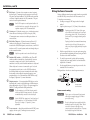
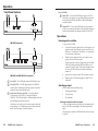
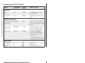
Operation, cont’d Selecting an input using contact closure Use one of the following methods to select an input via contact closure: • • • Using a contact closure device: If a two- or four-button contact closure device is connected to the SW USB’s Contact port, press the button on the device that corresponds to the SW USB input that you want to select (the first button on the left selects input 1, the second button selects input 2, etc.). Using a jumper wire: On the Contact port, insert one end of a small piece of wire into the ground (_) port and the other end into the port with the desired input number (1, 2, 3, or 4). Using an IR 102: Refer to your IR 102 User’s Manual for this procedure. Selecting an input using SIS commands You can also select an input via an RS-232 connection, using SIS commands. See chapter 4, “SIS Configuration and Control,” for a list of available SIS commands and their explanations. If an Extron A/V switcher is connected to the RS-232 Pass Thru port, the SIS commands that you enter can also be passed through to the connected switcher, even if the connected switcher has more inputs than the SW USB (see the next section). Issuing commands to an Extron A/V switcher via the RS-232 Pass Thru port The following table summarizes the two loop modes: Mode SIS commands issued via: SIS command to enable Loop 0 Contact closure, front panel, or RS-232 interface (Input selection SIS command X! ! only) E 0LOOP } Loop 1 RS-232 interface* E 1LOOP } * See the command/response table in chapter 4, “SIS Configuration and Control,” for an explanation of all supported SIS commands. SIS command processing in Loop 1 mode When an A/V switcher is connected to the RS-232 Pass Thru port and Loop 1 mode is enabled, the available SIS commands are processed in one of the following ways: • Passed through to the A/V switcher without being acted on by the SW USB • Performed by the SW USB and not passed through to the A/V switcher • Performed by the SW USB and passed to the A/V switcher, which also performs them. This applies only to the input selection command X! !. The table on the next page shows how the SIS commands are handled by an SW USB with a connected A/V switcher. (Unless otherwise indicated, commands are not case-sensitive.) You can configure the SW USB to pass commands through the RS-232 Pass Thru port to a connected A/V switcher in the following modes: 3-4 • Loop 1 mode: SIS commands that are issued to the SW USB via an RS-232 interface (such as HyperTerminal) on a computer or control system connected to the SW USB’s RS-232 port can be passed through to an A/V switcher connected to the RS-232 Pass Thru port. Loop 1 mode is the default mode. If you need to switch the SW USB to this mode, enter the SIS command E1LOOP}. • Loop 0 mode: The input selection SIS command X! ! (where X! is the input number) can be issued to the SW USB and the connected A/V switcher via the buttons on the SW USB front panel, contact closure, or the RS-232 interface. To enable Loop 0 mode, enter the SIS command E 0LOOP}. SW USB Series • Operation SW USB Series • Operation 3-5