1
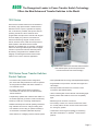
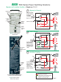
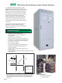
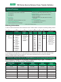
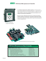
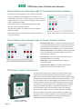
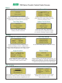
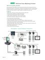
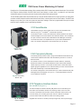
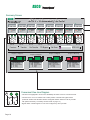
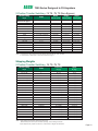
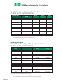
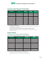
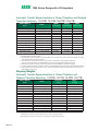
Series 7000
We Keep Your Power On
Power Switching and
Control Solutions for
Critical and Distributed
Power Applications
ASCO Series 7000
Critical Loads Demand ASCO
Healthcare Facilities
Commercial Buildings / Industrial Buildings
Web Hosting, Internet Data Centers
Telecom Central Offices
Process Manufacturing / Wafer Fabrication Plants /
Distributed Power / Load Management
As we become more
dependent on the quality and
reliability of electrical power,
interruption or complete loss
of power can create serious
and even crippling financial
losses, or impose dangers to
life and safety.
ASCO Power Technologies
(ASCO) provides the
solutions to handle the
transfer of critical loads to
emergency sources
reliably and with state of the
art products. Using ASCO
products can mean the
difference between a minor
inconvenience and a major
catastrophe. You’ll find ASCO
Power Transfer Switches
wherever there
is a critical load to be
protected.
Page 2
When flexibility in power
switching is a must, ASCO
offers a variety of product
solutions to meet virtually
every application requirement, including distributed
generation applications.
That’s why the 7000 Series
is available in open, delayed,
closed and closed soft load
configurations. Additionally,
switched or overlapping
neutral options
provide for reliable operation
of ground fault protection
systems and reduction of
voltage transients from
unbalanced load switching.
ASCO Power Transfer
Switches are the
first CE Marked, IEC 609476-1 compliant Transfer
Switches in the world which
have been certified by a
notified body of the
European Union.
ASCO
The Recognized Leader in Power Transfer Switch Technology
Offers the Most Advanced Transfer Switches in the World.
7000 Series
ASCO Power Transfer Switches are the standard of
the industry. High speed transfer of loads between
alternate sources of power, regardless of ampacity
size, is achieved by a reliable, field proven solenoid
operating mechanism. When combined with a
programmable microprocessor controller with keypad
and LCD display, they offer the most advanced
method of transferring all types of loads, such as
motors, electronic drives, UPSs and microprocessor
based systems. 7000 Series Power Transfer
Switches are available open or enclosed, in ampacity
sizes from 30 through 4000 amperes with the largest
selection of optional accessories offered anywhere.
All switching configurations are available with an
integrally mounted bypass-isolation switch and/or
rated for use in service entrance applications.
Fig. 1: Three Pole 7000 Series Automatic Transfer Switch
rated 1600 amperes (shown with optional front
connected terminals and Power Manager).
7000 Series Power Transfer Switches
Product Features
• Conventional two-position transfer configuration,
plus closed and delayed transition modes of operation.
All configurations available with either automatic or
non-automatic control.
• UL listed to 1008 Transfer Switch Equipment &
CSA certified to CSA 22.2 No.178-1978 Automatic
Transfer Switches.
• Independently qualified and certified to IEC 60947-6-1,
CE marked (optional). (Limited to certain accessories.)
• Rated up to 600 VAC, 30 through 4000 amperes.
• Reliable and field proven solenoid operating mechanism.
• High withstand and close-on ratings including short
time withstand current rating for optimum flexibility in
circuit breaker coordination (600-4000 amperes).
• Solid, switched, or overlapping neutral conductor options.
• Front replaceable main and arcing contacts (600-4000 amperes).
• Programmable microprocessor controller with keypad and
LCD display.
• Centrally located terminal block for customer control
connections (260-4000 amperes).
• 16mm, industrial grade control switches and indicating lights.
• Switch position LED indicators and source acceptability
lights.
• Standard ground conductor connections.
• Four auxiliary contacts, two contacts closed when switch
is in normal position and two contacts closed when switch
is in emergency position.
• Local/remote communications capability for interfacing
with ASCO PowerQuest ® or SiteWebTM communication
products.
Page 3
ASCO
7000 Series Power Switching Solutions
Closed-Transition Transfer Switching
ASCO Automatic Closed-Transition Transfer Switches feature
main contacts that overlap, permitting the transfer of electrical
loads without power interruption. The switch transfers in a
make-before-break mode if both sources are within acceptable
parameters. Control logic continuously monitors source
conditions and automatically determines whether the load
transfer should be open (conventional non-overlap mode) or
closed transition. Available 150 through 4000 amperes.
Closed-Transition Transfer within 5 electrical degrees is
achieved passively, without control of engine generator set.
Therefore, no additional control wire runs are required between
the ATS and engine generator set governor. Plus, protective
relaying may not be required under normal operation since
the contact overlap time is less than 100 milliseconds
(consult your local utility on protective relay requirements).
Failure to synchronize indication and extended parallel time
protection is built-in to all 7000 Series closed transition
controls to prevent abnormal operation.
Fig. 2: Four pole, Closed-Transition Transfer
Switch rated 1000 amperes in Type 1 enclosure.
Delayed Transition Transfer Switching
ASCO Delayed Transition Transfer Switches are designed
to provide transfer of loads between power sources with a
timed load disconnect position for an adjustable period of
time. Applications include older style variable frequency
drives, rectifier banks, and load management applications.
• Available 150 through 4000 amperes.
• Utilizes reliable, field proven solenoid operating
mechanisms.
• Mechanical interlocks to prevent direct connection of
both sources.
• Indicator light (16mm, industrial grade
type LED) for load disconnect position.
• Adjustable time delay for load disconnect position.
Fig. 3: Four pole, Delayed-Transition
Transfer Switch rated 2000 amperes.
Page 4
ASCO
7000 Series Power Switching Solutions
Non-Automatic Transfer Switching
ASCO Non-Automatic Transfer Switches are electrically
operated units which are operated with manual control
switches mounted locally or at remote locations.
• Sizes from 30 through 4000 amperes.
• Microprocessor based controller provides for addition
of optional accessories.
• Controller prevents inadvertent operation under low
voltage conditions.
• Low control circuit operating currents allow for long
line runs between remotely mounted manual control
switches and the transfer switch.
• Source acceptability lights inform operator if sources
are available to accept load.
• Standard inphase monitor can be activated for
transferring motor loads.
Fig. 4: Three pole Non-Automatic,
electrically operated 400 ampere switch
shown in Type 1 enclosure.
Withstand and Close-On Ratings for all 7000 Series Products(1)(2)
Switch Rating (Amps)
Transfer Switches
UL 1008 Withstand and Close-On Ratings at 480 Volts AC
Bypass Switches Current - Limiting Max. Fuse Type Specific Breaker
Fuse Rating
amps
Rating
types
“Any” Breaker
(3) Rating
Short Time
Withstand
Ratings(4)
Short Time
Duration
(Cycles)
30
-
100,000
60
J
10,000
10,000
N/A
-
70, 100, 150, 200
-
200,000
200
J
22,000
10,000
N/A
-
230
-
100,000
300
J
22,000
10,000
N/A
-
260, 400
150, 260, 400
200,000
600
J
42,000
35,000
N/A
-
600, 800,
600, 800
200,000
1600
L
65,000
50,000
36,0005
18
1000, 1200
1000, 1200
1600, 20006
1600, 2000
200,000
3000
L
100,000
100,000
65,000
30
3000
3000
200,000
4000
L
100,000
100,000
65,000
30
4000
4000
200,000
6000
L
100,000
100,000
65,000
30
Notes: 1) All values are available symmetrical RMS amperes and tested in accordance with the withstand and close-on requirements of UL 1008.
See publication 1128 for more information on withstand and close-on ratings for ASCO transfer switches.
2) Application requirements may permit higher withstand ratings for certain size switches. Contact ASCO for guidance if available short circuit current
exceeds the WCR ratings shown.
3) “Any” breaker ratings are based on 1.5 cycles for 30 - 230 amp & 3 cycles for 260 - 4000 amps. Applicable to breakers with instantaneous trip elements.
4) Short time ratings are provided for applications involving breakers that do not have instantaneous trips for system coordination.
5) Short time rating applicable to transfer switch design only.
6) Optional front connected service limited to 85,000 amps for specific and any breaker rating.
Page 5
ASCO
7000 Series Power Switching Solutions
Automatic Transfer Bypass-Isolation Switching
ASCO Automatic Transfer & Bypass-Isolation Switches are available
in open transition, closed transition and delayed transition designs.
The bypass and isolation features allow power transfer switches to
be inspected, tested, and maintained without any interruption of
power to the load.
• Available 150 to 4000 amperes.
• Allows bypass-isolation without load interruption.
• Bypass switch and transfer switch have identical electrical ratings.
• Heavy duty mechanical interlocks prevent undesirable operation.
• Bypass contacts carry current only during bypass mode.
• Transfer switch is drawout design for ease of maintenance.
• Bypass and isolation handles are permanently mounted. The bypass
switch has dead front quick-make, quick-break operation for
transferring of loads between live sources.
• Bypass switch is fully rated for use as a manual 3-position
transfer switch.
• Bypass and isolation functions are simple, requiring a total of two
operating handles.
Fig. 5: Three Pole 7000 Series Automatic BypassIsolation Transfer Switch Rated 1000 Amps
• No toggle switches, push buttons, selector switches or levers are
required for bypass-isolation operation.
• Mechanical indicators show bypass and transfer switch positions.
Transfer Switch Drawout Features (600-3000 amperes)
Automatic
Secondary
Disconnects
Automatic
Shutters
(optional)
Fig. 6: Bypass-Isolation Transfer
Switch secondary disconnects and
optional automatic shutters.
Page 6
• Automatic secondary disconnects
remove all control power as switch is
withdrawn.
• Drawout carriage provides for easy
transfer switch maintenance and/or
removal via commercially available
breaker hoists.
Self
Aligning
Jaws
• For optional transfer switch lifting yoke,
specify accessory 82B.
• For optional automatic shutters which
close when the transfer switch is
withdrawn to provide bus isolation,
specify accessory 82C.(1600-3000A
only)
Fig. 7: Bypass-Isolation
Transfer Switch self
aligning power jaws.
ASCO
7000 Series Power Switching Solutions
Bypass and Isolation Handles - Simple as 1, 2, 3
LED Indicators
Bypass switch
position
Source
availability
1
Bypass to Normal
Push in bypass
handle and turn
it counter
clockwise
Bypass Switch
Bypass Handle
Transfer
switch
position
Isolation
handle
position
E
L
Isolation Handle
N
Not in
“auto”
flashing
LED
Automatic Transfer Switch
2
Fig. 8: Transfer Bypass
Status Panel
Test Position
Bypass Switch
E
L
Mechanical
bypass
switch position
flags
Isolation Handle
Turn isolation
handle counter
clockwise until
window shows
“Test”
3
N
Automatic Transfer Switch
Isolation Position
Bypass Switch
E
L
Isolation
handle
Padlocking
provisions
Isolation Handle
Turn isolation
handle counter
clockwise
until window
shows “Isolate”
N
Automatic Transfer Switch
Key:
Mechanical isolation handle position
window (connected/test/isolate)
Fig. 9: Bypass-Isolation
Switch user interface
Represents Current Flow
In test position control panel remains
energized to allow for electrical
operation of a transfer switch.
Page 7
ASCO
7000 Series Service Entrance Power Transfer Switches
The ASCO Service Entrance Power Transfer
Switch combines automatic power switching with a
disconnect and overcurrent protective device on the
utility source. The power transfer switch meets all
National Electric Code requirements for installation
at a facility’s main utility service entrance. Service
entrance rated transfer switches generally are
installed at facilities that have a single utility feed
and a single emergency power source. A circuit
breaker serves as the utility disconnect and links
are provided to disconnect both neutral and ground
connections.
This product is UL 1008 and UL 891 listed and is
available up to 600V and 4000A in Standard,
Delayed, Closed Transition, Soft Load, and Bypass
Isolation Configurations.
Standard Features
•
•
•
•
•
•
•
•
•
•
Available from 150 to 4000 amperes
ASCO 7000 Series Power Transfer Switch,
UL 1008 Listed
Standard UL Type 1 Enclosure
Disconnect and overcurrent protective device on
the utility source: molded case circuit breaker 150
to 2000 Amp; insulated case 3000 to 4000 Amp
Disconnect link on Neutral
Disconnect link on Ground
Ground and Neutral Bus, all silver-plated copper
Solderless screw type terminals for External
Power Connections
Labeled UL 891, meets all NEC requirements for
service entrance
Internet Enabled Command and control available with optional
ASCO SiteWeb™
Ground Disconnect
Link
Utility
Circuit
Breaker
Neutral
Disconnect
Link
Ground Fault
Current
Transformer*
N
Load
Ø
Switched
Neutral
ATS
GFCT Ground Fault
Current
Transformer
ATS - Automatic Transfer
Switch
Ø
N
Emergency
One line diagram of a typical service entrance rated transfer
switch available in Solid, Switched or Overlapping Neutral
* Ground fault trip protection provided on sizes of 1000 amperes
and above
Page 8
Fig. 10: Ground and neutral
disconnect links
ASCO
7000 Series Service Entrance Power Transfer Switches
Optional Features
• Enclosures - Secure Double Door
• Surge Suppression
UL Type 3R w/strip heater & thermostat
•
UL Type 4X
UL Type 12
• Connections
Crimp lugs
•
Bus Riser on Normal, Emergency or Load
• Protective Relays/Metering
ASCO 5200 Series Power Manager
ASCO 451, 80KA Surge protector (see pg. 14)
Communications
ASCO 72A Communication interface module
ASCO PowerQuest ®
ASCO 5500 Series Thin Web Server for internet
connection
Additional Breaker(s)
Circuit Breaker on Emergency
Load Distribution Panel
Consult ASCO for additional features
Ordering Information
To order an ASCO 7000 Series Service Entrance Power Transfer Switch, complete the following catalog number.
7
A
US
+
Neutral
Code*
Product
A
Automatic
US
N
NonAutomatic
UB
CUS
CUB
DUS
DUB
B
Conventional
2-Position
Open
Transition
Bypass
Closed
Transition
Closed
Transition
Bypass
Delayed
Transition
Delayed
Transition
Bypass
--- No Neutral
A Solid Neutral
B Switched
Neutral
C Overlapping
Neutral
+
3
+
400
+
N
+ 5X
Phase Amperes Voltage
Poles
Code
2
3
70
100
150
200
225
250
400
600
800
1000
1200
1600
2000
3000
4000
C
D
E
F
H
J
K
L
M
N
P
Q
R
208
220
230
240
380
400
415
440
460
480
550
575
600
+
C
Grp
Code
Enclosure
C
5
5XM
optional
accessories N
P
Q
Type 1 enclosure
Type 3R secure
double door
Type 4 secure
double door
Type 4X secure
double door
Type 12 secure
double door
*Note. Switches rated 150, 600-3000 amps available with 2, 3 or either conventional switched neutral (4 poles)
or overlapping neutral (optional). For 4 pole applications on switches rates 260 to 400 amps and 4000 amps
specify overlapping switched neutral (optional). Conventional switched neutral is provided on delayed
transition transfer products when specified.
The Example Catalog Number above is 7AUSB3400N5XC (X is used to specify optional accessories).
Dimensions and Weights for non-bypass configurations only in type 1 enclosures.
Consult ASCO for all other product configurations.
Switch Rating
amps
Width
inches (mm)
Height
inches (mm)
Depth
inches (mm)
Weight
lbs (kg)
70 - 225
36.5 (927)
48.5 (1232)
13.25 (337)
408 (188)
250, 400
36.5 (927)
48.5 (1232)
13.25 (337)
408 (188)
600, 800
38 (965)
91 (2311)
28 (711)
820 (378)
1000-1200
38 (965)
91 (2311)
48 (1219)
1105 (510)
1600, 2000
38 (965)
91 (2311)
48 (1219)
2590 (1198)
3000
38 (965)
91 (2311)
72 (1829)
4590 (2148)
4000
46 (1168)
91 (2311)
72 (1829)
5640 (2609)
Page 9
ASCO
7000 Series Microprocessor Controller
The 7000 Series Microprocessor Based Controller is used with all sizes of
Power Transfer Switches from 30 through 4000 amperes. It represents the most
advanced digital controller in the industry and includes, as standard, all of the
voltage, frequency, control, timing and diagnostic functions required for most
emergency and standby power applications.
Because of severe voltage transients frequently encountered with industrial
distribution systems, the microprocessor logic board is separated and isolated
from the power board as shown below. This improves electrical noise immunity
performance and helps assure compliance with the rigorous transient suppression
standards highlighted below.
Fig. 11: 7000 Series
Microprocessor Controller.
Fig.12: Microprocessor Power and Logic PC Boards.
7000 Series Microprocessor Based Controller
Emission Standard - Group 1, Class A
Generic Immunity Standard, from which:
Electrostatic Discharge (ESD) Immunity
Radiated Electromagnetic Field Immunity
Electrical Fast Transient (EFT) Immunity
Surge Transient Immunity
Conducted Radio-Frequency Field Immunity
Voltage Dips, Interruptions and Variations Immunity
Page 10
EN 55011:1991
EN 50082-2:1995
EN 61000-4-2:1995
ENV 50140:1993
EN 61000-4-4:1995
EN 61000-4-5:1995
EN 61000-4-6:1996
EN 61000-4-11:1994
ASCO
7000 Series Microprocessor Controller
Features
• Digital microprocessor.
• Touch pad programming of features and settings
without the need for meters, or variable power supplies.
• Sixteen (16) selectable operating voltages available in
a single Controller.
• On-board diagnostics provide control panel and ATS
status information to analyze system performance.
• Displays and counts down active timing functions.
• Password protection to prevent unauthorized tampering
of settings.
• Serial communications board (RS-485 protocol)
for remote monitoring and control with ASCO
PowerQuest ® and SiteWeb™ communications
products. Specify optional accessory 72A.
• Load shed option for SYNCHROPOWER® bus
optimization applications. Specify optional accessory 30B.
• Selectable multi-language display
(English, German, Portuguese, Spanish, or French.
For others contact ASCO).
Voltage and Frequency Sensing
Time Delays
• 3-Phase under and over voltage settings on normal
and emergency sources.
• Engine start time delay - delays engine starting signal to
override momentary normal source outages - adjustable
0 to 6 seconds.
• Under and over frequency settings on normal and
emergency.
• True RMS Voltage Sensing with +/- 1% accuracy;
Frequency Sensing Accuracy is +/- 0.2%.
• Transfer to emergency time delay - adjustable 0 to 60
minutes.
• Selectable settings: single or three phase voltage
sensing on normal and emergency; 50 or 60Hz.
• Emergency source stabilization time delay to ignore
momentary transients during initial generator set
loading - adjustable 0 to 6 seconds.
• Phase sequence sensing for phase sensitive loads.
• Retransfer to normal time delay with two settings:
• Voltage unbalance detection between phases.
• Power failure mode - 0 to 60 minutes.
• Test mode - 0 to 60 minutes.
Status and Control Features
• Output contact (N/O or N/C) for engine-start signals.
• Selection between “commit/no-commit” on transfer
to emergency after engine start and normal restores
before transfer.
• Advanced inphase algorithm which automatically
measures the frequency difference between the two sources
and initiates transfer at appropriate phase angles to
minimize disturbances when transferring motor loads.
• Unloaded running time delay for engine cooldown adjustable 0 to 60 minutes.
• Pre and post transfer signal time delay for selective
load disconnect with a programmable bypass on source
failures - adjustable 0 to 5 minutes. This signal can be
used to drive a customer furnished relay, or for (2) sets
of double throw contacts rated 3 amps at 480 volts AC,
specify ASCO optional accessory 31Z.
• Event log displays 99 logged events with the time and
date of the event, event type and event reason.
• Fully programmable engine exerciser with seven
independent routines to exercise the engine generator,
with or without loads, on a daily, weekly, bi-weekly or
monthly basis.
• Output signals for remote indication of normal and
emergency source acceptability
• Contains all alarm signals, logic and time delays for
use with closed transition switches.
• Statistical ATS/System monitoring data screens which provide:
• Insynch time delay - 0 to 3 seconds.
• Total number of ATS transfers.
• Failure to synchronize - 1 to 5 minutes.
• Number of ATS transfers caused by power source failure.
• Extended parallel - 0.1 to 1.0 seconds.
• Total number of days ATS has been in operation.
• Total number of hours that the normal and emergency
sources have been available.
• Delayed transition load disconnect time delay adjustable 0 to 5 minutes.
Page 11
ASCO
7000 Series User Controls and Indicators
Control Switches and Indicating Lights for Conventional 2-Position Switches
• Switch position indicating lights (16 mm, industrial grade LEDs).
• Source acceptability indicating lights with true indication of the
acceptability of each source, as determined by the voltage, frequency,
voltage unbalance, and phase sequence settings of the control panel
(16mm, industrial grade LEDs).
• Three position (16mm, industrial grade type) selector switch:
• Automatic: Normal maintained position.
• Test: Momentary position to simulate normal source failure for
system test function.
• Reset Delay Bypass: Momentary position to bypass transfer and
re-transfer time delay.
Fig. 13: 7000 Series User Controls and Indicators.
Control Switches and Indicating Lights for Closed Transition Switches
• Extended Parallel Time - Provides visual indication when the
pre-set extended parallel time has been exceeded. The controls
automatically open the emergency or normal main contacts.
Separate contact also available to shunt trip external breaker.
• Failure To Synchronize - Visually displays a failure to synchronize
alarm if the time delay settings is exceeded, during closed
transition transfer operation.
• TS Locked Out - Prevents transfer in either direction if the
extended parallel time is exceeded.
Fig. 14: 7000 Series User Controls and Indicators.
• Alarm Reset - Resets extended parallel and failure to
synchronize alarms.
• Closed Transition Bypass - Pushbutton allows transfer
between sources in an open transition mode.
7000 Series Transfer Control Center
The 7000 Series microprocessor controller is a Transfer Control Center
which allows the user to easily access detailed information on: system
status; power source parameters; voltage, frequency and time delay settings;
optional feature settings; historical event log; and system diagnostics. A four
line, (20) character LCD has a backlit display which enables easy viewing
under all conditions. The user can navigate through all screens using only
six buttons, which also allows selection of: (18) different source parameter
settings; (16) standard time delays; (12) standard feature settings; up to
seven independent engine exercise routines; and even the language
(English, German, Spanish, French, etc.) which appears on the display.
Since the Transfer Control Center must be visible and operable through
the enclosure door, it has been qualified for use in industrial and outdoor
applications. This includes installation in Type 3R (outdoor/rainproof),
4 (weatherproof) and 12 (indoor/industrial) enclosures.
Fig. 15: 7000 Series
Transfer Control Center.
Page 12
ASCO
7000 Series Transfer Control Center Screens
Status
System Status
Normal OK
Load on Normal
Displays system status in clear, concise language.
Message shown indicates normal source is acceptable
and the load is connected to the normal source.
Source Status
Normal Source
Vab=480V....................ABC
Vbc=480V.........Vunbal=1%
Vca=480V................60.0Hz
Displays voltage for each phase, frequency,
phase rotation and voltage unbalance for both
normal and emergency sources.
Time Delay Status
Inphase Transfer Mode
Normal OK
Emerg OK
TD.Engine.Cooldown:
4min15s
Waiting for In-Sync
-45o
0.02Hz
Active time delay status displays time
remaining until next control event.
Displays the relative phase angle between
sources and frequency differential to indicate
the controller is awaiting an inphase condition.
Settings
Voltage and Frequency Settings
Time Delay Settings
Normal Voltage
Dropout.............85%.408V
Pickup...............90%.432V
O.V. Trip.........110%.528V
TD N>E Xfer Signal
Bypass if N Fail: No
Pre Xfer: 0 min 20S
Post Xfer: 0 min 20S
Provides voltage and frequency setting values for
normal and emergency sources. Voltage pick-up,
dropout and trip settings are set in percentage of nominal
voltage and are also displayed in rms voltage values.
Engine Exerciser
P1..................Engine.Exerciser
Enable:.....Yes....WLoad:....Yes
Start:19h30. ALL MON
Run.Time:...............2h15min
Seven independent programs, load/no load
selection, flexible run times and daily, weekly,
bi-weekly and monthly exercise routines.
Provides direct reading display for setting time delays.
Feature Settings
Shed Load
Direction:
Inphase: No
From E
TD/0.25
Standard features can be activated with the keypad. As an
example, when enabled, the “shed load” option causes the
transfer switch to transfer the load off of the specified source.
If desired, the load shed transfer can be made inphase.
Data Logging
ATS Statistics
Historical Event Log
ATS Statistics
ATS Total Xfers: 46
SRC Fail Tot Xfers: 20
Days Energized: 36.5
16.AUG02/95..........13h10:17
Eng.Start...............NormFail.
15.AUG02/95...........13h10:25
Xfer.N>E................................
Instant availability of statistical information on total number of
ATS transfers, number of transfers caused by power failures
and total days controller has been energized, plus more.
Displays detailed information for last 99 events,
including time of occurrence, length of event,
date and reason for event.
Page 13
ASCO
7000 Series Optional Accessories
Time Delays
Neutral Conductor Options
2C
• Solid neutral, with fully-rated terminals. (AL-CU) UL Listed.
1G
The standard feature one time delay is adjustable
from 0 to six seconds to delay engine starting. If
necessary, extended time delay on engine starting
is available. Adjustable from 0 to 60 min in one
second steps. Factory set at five minutes.
Similar to accessory 2C except using 24 volt DC
external input signal.
Manual Controls for Automatic
Transfer Switches
6C
6D
Reset switch for manual retransfer to normal with
automatic retransfer in the event of emergency
source failure.
Selector switch for automatic/manual retransfer to
normal. Automatic bypass if emergency fails.
Engine Generator Controls
and Accessories
12
Three position engine control selector switch.
Positions: 1- Stop 2 - Automatic 3 - Engine Test
• Conventional neutral switching pole.
• Overlapping neutral transfer contacts. Allows for proper
ground-fault sensing and avoids generator voltage
transients during transfer.
Note: Specify neutral option in catalog number, see page 21 for instructions.
Extension Harness
37B
Analog Load Metering Options
23B
Three phase ammeter with selector switch
(with current transformers and shorting blocks).
24B
Three phase voltmeter with selector switch.
Note: Refer to ASCO 7000 Series Data Monitor on page 15 which provides
voltage, frequency and power monitoring.
Serial Communications
72A
Note: Switches with accessory 12 must be labelled as a non-automatic
transfer switch according to UL 1008.
Engine controls containing “engine stop” positions should be located at the
engine generator. (Consult ASCO for application assistance.)
Indicators
14A/14B Additional auxiliary contact sets to indicate switch
position. Two sets are standard. Specify total
number of sets if more are required.
18B
Six foot (6’) extension harness to increase distance between
transfer switch and control panel on open-type units.
Serial communication module for remote
communications to ASCO PowerQuest® products.
Surge Protection
ASCO Pulsar 450 rated 40KA
73AC1 Normal source protection. (3Ø, 4wire WYE)
73AC2 Emergency source protection. (3Ø, 4wire WYE)
73AC3 Load side protection. (3Ø, 4wire WYE)
Note: Other distribution voltages available (Contact ASCO).
Two-pole, double-throw contacts operate when
emergency source voltage is present at transfer
switch terminals.
Special Applications
18G
Two-pole, double-throw contacts operate when normal
source voltage is present at transfer switch terminals.
111B Generator - to - Generator for Prime Power
Applications
99
“Push-to-Test” feature on all pilot light indicators.
Customer Control Circuits
30A
Load-shedding circuit initiated by opening of a
customer-supplied contact.
30B
Load-shedding circuit initiated by removal of
customer-supplied control voltage. (Specify voltage).
31Z
Selective load disconnect control contacts (two
provided) which operate with time delay prior to
and/or after load transfer and retransfer.
43R
Page 14
Terminal block for all customer control connections
on 30-150 amp only (standard on all other sizes).
111A Generator - to - Generator for Standby Applications
Bypass Isolation Switch Options
14A1
Auy contact to close in “Bypass to Normal” position.
14B1
Auxiliary contact to close in “Bypass to Emergency” position.
14T
Auxiliary contact to close when transfer switch is in
“Automatic” position.
14U
Auxiliary contact to close when transfer switch is in
“Isolate” position.
14V
Auxiliary; contact to close when transfer switch is in
“Test” position.
Note: An externally operable quick-make, quick-break (QMQB), manual handle is available on some 7000 Series product configurations.
(Consult ASCO for guidance.)
ASCO
ASCO
7000 Series Optional Accessories
Power Manager
POWER SYSTEM TOTAL
404 KW
+1.00 PF
0 KVAR
60.00 Hz
404 KVA
ATSºn NORM
The ASCO Power Manager is a microprocessor based
metering device that provides real-time measurements
of single and three phase power systems. The Power
Manager uses digital signal processing technology to
measure voltage and current per phase; real, reactive
and apparent power, and bi-directional energy. All
measurements can be viewed locally with a backlit
liquid crystal display and/or displayed remotely with
ASCO PowerQuest ® or SiteWeb™ products.
Direct voltage input for systems up to 600 Volts AC
can be monitored without the use of external potential
transformers (PTs). Measures three phase currents and
a fourth current input is available for measuring current
in the neutral conductor. The Power Manager includes
one discrete input for transfer switch position, eight
general purpose discrete inputs, and four relay outputs
for controlling or monitoring external devices.
Power Metering
• Voltage:
Line - Line: VAB, VBC, VCA, VAVERAGE
Line - Neutral: VAN, VBN, VCN, VAVERAGE
• Frequency: 45.0 to 66.0 Hertz
Fig. 16: ASCO Power Manager.
Configurable Designations
• Local - A four line 20 character LCD backlit display.
• Remote - With optional Acc. 72A communication module
and Power Manager monitoring systems.
• Provides a user programmable setpoint based on watt
demand and can be used to control one of the four relay
outputs. Used for peak shaving applications
Integrated ATS Features
• When configured on load of ATS:
• Current: IA, IB, IC, IAVERAGE
• Displays ATS position.
• Unbalance %: Voltage, Amps
• Displays power data as a function of ATS position
(normal/emergency).
• Real Power: KWA, KWB, KWC, KWNET
• Reactive Power: KVARA, KVARB, KVARC, KVARNET
• Apparent Power: KVAA, KVAB, KVAC, KVANET
• Accumulates energy data separately for normal and
emergency sources.
• Real Energy: KWHIMPORT, KWHEXPORT, KWHNET
• Reactive Energy: KVARHIMPORT, KVARHEXPORT,
KVARHNET
• Power Factor: PFA, PFB, PFC, PFNET
Data Access
• Eight digital inputs, four relay outputs.
• Input/Output 15-character, user definable screen
display for identification of input/output signals.
Optional Configurations and
Connection Arrangements
Connected To:
Load
Normal
Emergency
Load (BPS only)
With Display
Acc. 85L
Acc. 85N
Acc. 85M
Acc. 85R*
Without Display
Acc. 75L
Acc. 75N
Acc. 75M
Acc. 75R*
Add suffix “A” to above designations if neutral conductor monitoring is required.
Note: Accessory 75 and 85 includes component mounting, CTs, shorting
blocks and all necessary interwiring.
* Bypass & isolation switch contacts wired to discrete Power Manager
inputs.
Note: The ASCO Power Manager is also available as a separate unit for monitoring electrical parameters anywhere in the power distribution system.
Page 15
ASCO
7000 Series Power Monitoring & Control
ASCO Connectivity Solutions
ASCO PowerQuest® and SiteWeb™ communications products allow for the monitoring and control of
power transfer switches in your Emergency or Standby Power Distribution System. Local Area networks
and Remote networks are supported with either single or multiple points of access, and web-enabled
communications allow access to your power system from anywhere around the world.
Features
• Monitors and Controls Power Transfer Switches and Engine Generators
• Monitors Normal and Emergency Voltages and Frequency
• Indicates Transfer Switch Position and Source Availability
• Provides Transfer and Retransfer of Loads for System Testing
• View Normal and Emergency Voltage and Frequency Settings
• View Transfer Switch Time-Delay Settings
• Provides Transfer Switch Rating and Identification
• Automatic Paging Notifies Personnel, by E-mail or Pager, of Selected System Alarms
• View Current, Power and Power Factor with ASCO Power Managers Connected to the System
• Adjust and Set Transfer Switch Controller Parameters
• Activate Transfer Switch Control Functions, Such as Inphase Transfer, Selective Load Disconnect
Time Displays and Engine Exerciser Programming
• View Transfer Switch Event Log
• Provides Transfer Switch Test Schedule
PowerQuest ® Typical Network Connection
ASCO 5110 (72A) Serial Modules
Dial - Up
ASCO 5200
Power
Manager
ASCO 5100
Telephone
Interface
Module
ASCO
PowerQuest
VPi 32.15
Software
To Additional
Automatic
Transfer
Switches
Generator
ASCO
ATS 1
Serial
ASCO 5200
Power Manager
RS-485
ASCO
ATS 2
ASCO 5110 (72A) Serial Modules
Generator
To Additional
Automatic
Transfer
Switches
Ethernet
ASCO 5150 (72E)
Connectivity Module
Page 16
ASCO
ATS
ASCO
ATS 1
ASCO
ATS 2
ASCO
7000 Series Power Monitoring & Control
PowerQuest is a PC based software package. When combined with the ASCO Communication Interface Module (Acc 72A), the ASCO
5120 Telephone Interface Module and ASCO 5200 Series Power Manager, as shown above, it provides the most economical
communication system for monitoring and control of power transfer switches and engine generators.
The local RS-485 network allows communications with up to 32 power transfer switches and four engine generators. An analog phone
connection and ASCO telephone interface module allow for direct dial up, monitoring and control of remote locations. The ASCO Power
Manager not only allows you to view current power and power factor readings, but also has a programmable KW set point to initiate
transfer of loads to a standby source for peak shaving operations.
5110 Serial Module
Serial Module (5110) is used to allow local or remote communications with
ASCO PowerQuest ® or SiteWeb™ communication products.
The module is used to connect the 7000 Series Transfer Switches, and ASCO
Power Managers to the serial network via an RS-485 interface. The module has
two port connectors used for ATS & Standalone Power Manager connectivity.
The serial connection is accomplished from a 5-pin terminal header/socket
block. The module is designed to communicate with up to 32 devices.
Fig. 17: Serial
Module 72A
5150 Connectivity Module
Connectivity Module (5150) is used to bring several different serial devices that
communicate at different baud rates and with different protocols to a common
Ethernet media.
The module is used to connect 7000 Series Transfer Switches, and ASCO
Remote Annuciators to the standard Ethernet TCP/IP network with standard
10base T(RJ-45) connector. The module has been built in customized JAVATM
applets (program applications for an internet browser) for each monitored device
that loads automatically to a standard Web Browser.
The module is designed to communicate with up to 8 clients simultaneously with
Web applications (web pages), PowerQuest ® , or third party Modbus devices
over an Ethernet connection.
Fig. 18: Connectivity
Module 72E
5100 Telephone Interface Module
(for use with PowerQuest ® )
The ASCO Telephone Interface Module (TIM) allows users to dial directly into
their ASCO communications network for monitoring and/or control. The TIM
connects to the ASCO communication network via RS-485 and the phone port
connects directly into an analog phone jack. Also, the TIM has an RS-232
connector which allows the TIM to be used as the dialing modem.
Fig. 19: Telephone
Interface Module
Supplied with 120 VAC to 18 VDC (nominal) UL approved, class 2 power supply.
Page 17
ASCO
®
Summary Screen
ᓼ
ASCO
ATS 1 - 8 Summary Screen
1901 lavg
548 KW
1901 lavg
548 KW
208 NVca
0 EVca
208 NVca
0 EVca
ATS 1
E
N
E
N
N
Transfer
Engine 1 Stopped
0
0.00
0.00
0
0
KW Total
Frequency
Power Factor
Vavg.
lavg.
L
E
N
OTTS
Previous
N
N
1901 lavg
548 KW
1901 lavg
548 KW
1901 lavg
548 KW
1901 lavg
548 KW
208 NVca
0 EVca
208 NVca
208 EVca
208 NVca
208 EVca
208 NVca
208 EVca
ATS 4
ATS 3
L
E
OTTS
E
208 NVca
0 EVca
ATS 2
L
E
1901 lavg
548 KW
E
N
L
E
E
OTTS
N
L
N
E
N
OTTS
Re-Transfer
ATS 6
ATS 5
E
N
L
N
E
OTTS
E
N
N
E
E
N
E
N
E
OTTS
Engine 2 Stopped
Engine 3 Stopped
Engine 4 Running
0
0.00
0.00
0
0
0
0.00
0.00
0
0
136
60.01
0.82
208
472
KW Total
Frequency
Power Factor
Vavg.
lavg.
N
OTTS
ATS 9-16
KW Total
Frequency
Power Factor
Vavg.
lavg.
N
L
?
TD Bypass
KW Total
Frequency
Power Factor
Vavg.
lavg.
Convenient One-Line Diagram
• Colored icons highlighted to show source availability and which source is connected to load.
• Contacts move on icon to indicate main contact position of transfer and bypass switch.
(Automatic transfer and automatic transfer and bypass isolation switches must be provided
with optional accessory 14 auxiliary contacts shown on page 14.)
• Bypass switch contacts appear on icon when configured by user input data.
Page 18
ATS 8
L
OTTS
Re-Scan
0 NVca
208 EVca
ATS 7
L
E
472 lavg
136 KW
ASCO
Power Manager Detail Screen
Power Manager / Data Monitor Screen
ᓼ
ASCO
®
ADDRESS
8
Current
Voltage
• Voltage: phase to phase; phase to neutral and
voltage unbalance.
Normal Energy
475
KWH imp
890763
KVARH lag
Voltage BC
209
Current B
469
KWH exp
0
KVARH lead
78
Voltage CA
208
Current C
472
KWH net
890763
KVARH net
163
• 3 phase currents and neutral (optional).
Voltage AN
119
Unbal %
40
Voltage BN
120
2
Voltage CN
121
• Frequency.
Voltage AB
Current A
207
85
Emergency Energy
KWH imp
21
KVARH lag
KWatt
136
KWH lead
7
KVARH lead
1
Unbal % L-L 1
KVAR
0
KWH net
25
KVARH net
3
Frequency
KVA
136
Power
59.97
Reset Normal
• Kilowatt hours - normal and emergency.
Reset Emergency
Power Factor 1
• Status and control of four relay outputs.
Digital Input
Toggle
Status
Status Input 1
Start Engine
Relay 1
on
CT Ratio
1000
Bypass to Normal
Output 2
Relay 2
off
PT Ratio
120
Bypass to Emergency
Output 3
Relay 3
Previous
off
ATS Test
Output 4
Relay 4
Previous
off
Digital Output
Status
Device
• Status of eight digital inputs.
• Device ratings: CT and PT ratio.
ATS Isolated
Normal Breaker Trip
ATS Summary
Status Input 7
Status Input 8
NONE
USER
Transfer Switch Detail Screen
ASCO
ATS Details Screen
ᓼ
Transfer Switch
• ATS rating and identification data is displayed.
Description ATS 8
• Allows remote testing and time delay bypass.
8
205 NVca
0 EVca
ATS1
PRESENT STATE
Transfer
• Voltage, frequency, phase sequence, voltage unbalance
and time delay settings can be checked.
L
E
PC
Normal OK
6/15/99
11:08:54 AM
Timer Bypass
OTTS
Normal Voltage Frequency Settings
Voltage or Freq % Nom
• Provides complete system status message from
7000 series microprocessor controller.
Value
Time Delay Settings
Engine Start-Norm Fail
00 : 10
Voltage P.U.
95
197.6
Norm to Emerg
Voltage D.O.
70
197.6
Emerg to Norm-Src Fail
30 : 00
Voltage Trip
Freq P.U.
0
95
0
47.5
Emerg to Norm-Test Xfer
02 : 00
Emerg to Norm-Emerg Fail
00 : 00
Engine Cool Down
03 : 00
90
45
• View event log on the last 99 events for each ATS.
Freq Trip
0
0
Volt Unbal P.U.
10
20.8
Select
Standard TD
• Arrange test schedules for transfer switches.
Volt Unbal D.O.
20
41.6
Pre/Post Signal TD
Select Emergency Settings
• Provides for monitoring of local site or remote sites.
USER
Current
Power
Energy
Voltage AB
207
Current A
475
KW Total
136
KWH imp
890784
KVARH lag
85
Voltage BC
209
Current B
469
KWH net
43441
KWH exp
0
KVARH lead
78
60
KWH net
890784
KVARH net
163
208
Current C
472
Frequency
Voltage AN
119
Unbal %
40
Power Factor 60
Voltage BN
120
Voltage CN
121
Unbal % L-L
1
Digital Input
Alarm
Enabled
Digital Output
Toggle
Status
Start Engine
Relay 1
on
No
Relay 2
off
Low Oil Pressure
Yes
Output 3
Relay 3
Previous
off
Bypass Closed
No
Output 4
Relay 4
Previous
off
Bypass on Test
No
Normal Brkr Temp
No
Status Input 7
No
Status Input 8
No
NONE
50
# Phases
1
Normal Vab
202
Normal Vbc
205
Normal Vca
205
Normal Freq
59
Emerg Vab
0
Emerg Vbc
0
Emerg Vca
0
Emerg Freq
0
Update Time
Event Logging (Max. 99 Entries)
1
Emerg Became
Not Vail
Emergency
Failure
Event Log
Event Cause
Date
06/12/01
Time
16:05:42
Test Schedules
ATS Summary
• Current for each phase.
• Kilowatts and kilowatt hours total.
• Status and control of four digital outputs which can be
customized by the user.
Output 2
USER
1200
Nom Freq
• Frequency and power factor.
Reset
No
Engine Oil Temp
Low Fuel
None
208
Current Rating
• Voltage: Phase to phase; Phase to neutral
4
Voltage CA
Non - Standard TD
6/13/99
10:02:42
Switch Data
Nom Voltage
Engine-Generator Details
Engine-Generator Screen
Voltage
CP
[min]:[sec]
00 : 03
Freq D.O.
ENGINE
N
Re Transfer
• Displays phase to phase voltage on normal and
emergency.
ᓼ
In-Phase
Monitor
Enabled
Yes
Load On Normal
• Viewing of engine exercise schedules.
ASCO
ATS
Locked Out
N0
Ver. ADRTST-E12
Location Switch 1
Status
• Status of eight digital inputs.
• “Alarm Enabled” selection. These alarms flash the
“engine-generator” icon on the summary screen.
• Digital inputs for engine malfunctions are derived
from engine mounted sensors (supplied by others).
ATS Summary
Page 19
ASCO
SiteWebTM
Remote Access
Computer
Local Computer
Ethernet
RS 485
Ethernet Hub
Internet
Firewall
Pager
ASCO 5500
Thin Web
Server
Email Server
Ethernet
Monitoring
and Control
Ethernet Hub
RS 422 Modbus
Building
Management
Computer
RS 485
Monitoring
Monitoring and Control
ASCO
Engine Generator
Paralleling
System
ASCO
5110 (72A)
Serial
Modules
To Additional
Automatic
Transfer
Switches
ASCO
ATS 1
Page 20
ASCO
ATS 2
ASCO
5150 (72E)
Connectivity
Modules
To Additional
Automatic
Transfer
Switches
ASCOA
TS 1
ASCO
ATS 2
ASCO
SiteWebTM
SiteWebTM is a client-server application requiring no software to be installed on the client computer. When combined with the ASCO
Communication Interface Modules (Acc 72A / Acc 72E), the ASCO 5500 Series Thin Web Server and the ASCO 5200 Series Power Manager,
as shown above, it provides the most comprehensive Intranet and Internet communication system for the monitoring and control of power
transfer switches and engine generators located in your emergency or standby power distribution system.
The SiteWebTM communication system allows multiple client access, from local or remote locations, and provides for the monitoring of up to
64 power transfer switches and eight engine generators. In addition, automatic paging is provided for all alarm signals.
5500 Series Thin Web Server
(for use with
products)
The ASCO Thin Web Server allows you to monitor and control transfer
switches and engine generators anytime over the Internet
or an Intranet from anywhere in the world. It also transmits a page
message that an alarm has occurred with one or more of the transfer
switches. Plus, this is possible from your home computer or
anywhere that has Internet service, using the ASCO Thin Web Server
single-board computer with its embedded SiteWeb™ HTML web pages.
Fig. 20: Thin Web Server
Communications Products for Series 7000 Transfer Switches
Description
Acc. Option
Serial Module
72A
Connectivity Module
Catalog No.
5110
72E
5150
Telephone Interface Module for Remote Monitoring*
—
5120
Power Manager with Display*
—
5200D
Thin Web Server*
—
5510E
Thin Web Server with Modem*
—
5510M
PowerQuest VPi Software Package*
—
VPi 32.15
*Note:
These products are available as separate items only. They can be ordered by catalog numbers shown in above chart.
Connectivity Modules
PowerQuest ®
ASCO Connectivity Solution Guide
Feature
PowerQuest
Vpi 32.15
Thin Web Server
with SiteWeb
Series 5150
Connectivity Module
Quantity of Monitored / Controlled Power Transfer
Switches per LAN
32
64
1024+
Number of Monitored / Controlled Gensets
1024+
4
8
Control & Monitoring Capability
Yes
Yes
No
Embedded Web Pages
No
Yes
Yes
Ethernet Network Compatible
Yes
Yes
Yes
Monitor Multiple Protocols & Baud Rates
(ASCO I, ASCO II, Modbus)
No
No
Yes
Monitor Multiple Sites
Dial-Up
Internet
Intranet
Multiple Client Access
No
Up to 8
Up to 8
Client Software Required
Yes
Internet Explorer
Internet Explorer
Monitors Dissimilar ASCO Controllers on Common LAN
No
No
Yes
Communicates with ASCO Remote Annuciators
No
No
Yes
Email / Paging Alarms
No
Yes
No
Historical Trending Option Alarms
No
Yes
No
Page 21
ASCO
7000 Series Ordering Information
To order an ASCO 7000 Series Power Transfer Switch, complete the following catalog number:
A
7
TS
A
+
Neutral
Code*
Product
A
N
M
Automatic
NonAutomatic
Manually
Operated
TS
Conventional
2-Position
TB
Open
Transition
Bypass
CTS
Closed
Transition
CTB
Closed
Transition
Bypass
DTS
Delayed
Transition
DTB
Delayed
Transition
Bypass
---
No Neutral
A
Solid
Neutral
B
C
3
+
+
400
Phase
Poles
Amperes
2
3
30
70
100
150
200 *
230 *
260
400
600
800
1000
1200
1600
2000
3000
4000
Switched
Neutral
Overlapping
Neutral
N
+ 5X +
C
Voltage
Code
Grp
Code
Enclosure
+
A
B
C
D
E
F
115
120
208
220
230
240
H
J
K
L
M
N
P
Q
R
5
5X-
---
No enclosure
C
Type 1 enclosure
E
Type 2 enclosure
F
Type 3R
enclosure
380
G
Type 4 enclosure
400
415
440
460
480
550
575
600
H
Type 4X
enclosure
(stainless steel)
K
Type 7 enclosure
L
Type 12
enclosure
M
Type 3R secure
double door
N
Type 4 secure
double door
P
Type 4X secure
double door
Q
Type 12 secure
double door
optional
accessories
*Note: Switches rated 30-230, 600-3000 amps available with 2, 3 or either conventional switched neutral (4 poles) or overlapping neutral (optional).
For 4 pole applications on switches rated 260 to 400 amps and 4000 amps specify overlapping switched neutral (optional).
Conventional switch neutral is provided on delayed transition transfer products when specified.
200 and 230 amp switch limited to 480 volts maximum.
The Example Catalog Number above is 7ATSA3400N5XC
(X is used to specify optional accessories).
Transfer Switch Configurations
Transfer/Bypass Configurations
7A TS, 7N TS, 7A DTS, 7A CTS, 7N DTS, 7N CTS
7A TB, 7N TB, 7A DTB, 7A CTB, 7N DTB, 7N CTB
Sizes of UL-Listed Solderless Screw-Type
Terminals for External Power Connections
Sizes of UL-Listed Solderless Screw-Type
Terminal for Power Connections
Switch Rating Max # of Conductors
amps
per Terminal
Switch Rating
amps
Max # of Conductors
per Terminal
Range of AL- CU
Conductor Sizes
30 -2303
One
#14 to 4/0 AWG
260-400
One
#4 AWG to 600 MCM
Two
#1/0 AWG to 250 MCM
6004
150,260,400
Range of AL-CU
Conductor Sizes
One
# 4 AWG to 600 MCM
Two
# 1/0 AWG to 250 MCM
Two
# 2 AWG to 600 MCM
Four
# 1/0 AWG to 600 MCM
600
Two
#1/0 AWG to 600 MCM
800,1000,12004
800-12001
Four
#1/0 AWG to 600 MCM
1600-20004
Six
# 1/0 AWG to 600 MCM
#1/0 AWG to 600 MCM
30004
Ten
# 2 AWG to 600 MCM
#1/0 AWG to 600 MCM
4000
Twelve
# 2 AWG to 600 MCM
1600-2000
3000
40002
Six
Twelve
Suitable for Bus Bar Connection or Lugs Can Be Field Modified
Notes: 1. Unit is designed for top cable entry of emergency and load and bottom
entry of normal. Optionally, the switch may be supplied with reverse
source and/or bottom entry load, when specified.
2. All main terminals are rear connected. The 4000 amp switch is
arranged for bus bar connection. Contact ASCO if provisions for cable
connection are required.
Page 22
4
3. 200 and 230 amp rating for copper conductors only.
4. All main terminals are rear connected. A front connected version is
available in 600 and 800 amp ratings only with top cable entry only.
See pages 24 and 25 for dimensional data.
ASCO
7000 Series Designed to Fit Anywhere
2-Position Transfer Switching 7A TS, 7N TS (Non-Bypass)
Switch Rating
amps
Poles
Width
inches (mm)
Height
Depth
inches (mm) inches (mm)
Enclosed UL Type 12
30, 70, 100, 150, 200, 230 2, 3 or 3 with neutral A/B/C
260, 400
2, 3 or 3 with neutral A/C
600, 800, 1000
2, 3 or 3 with neutral A/B/C
1200
2, 3 or 3 with neutral A/B/C
1600, 20001
2, 3 or 3 with neutral A/B/C
30001
2, 3 or 3 with neutral A/B/C
40001
2, 3 or 3 with neutral A/C
18 (457)
22 (559)
34 (864)
38 (965)
38 (965)
38 (965)
46 (1168)
48 (1219)
48 (1219)
72 (1829)
87 (2210)
91 (2311)
91 (2311)
91 (2311)
13 (330)
13 (330)
20 (508)
23 (584)
48 (1219)
60 (1524)
72 (1829)
10-1/4 (260)
12 (305)
14-1/2 (368)
27 (686)
33-1/4 (845)
33-1/4 (845)
41 (1041)
10-1/4 (260)
18-1/2 (470)
18-1/2 (470)
31 (787)
28 (711)
28 (711)
52 (1321)
5-1/2 (140)
6-7/8 (175)
6-7/8 (175)
12-7/8 (327)
26-1/4 (667)
30-3/4 (781)
25-1/2 (648)
Open Configuration
30, 70, 100, 150, 200, 230
260, 400
260, 400
600, 800, 1000, 1200
1600, 2000
3000
4000
2, 3 or 3 with neutral B/C
2 or 3
2 or 3 with neutral C
2, 3 or 3 with neutral B/C
2, 3 or 3 with neutral B/C
2, 3 or 3 with neutral B/C
2, 3 or 3 with neutral C
Notes: 1. Enclosures for 1600 - 4000 amp are free-standing with removable top, sides, and back.
2. Consult ASCO for dimensions on enclosures other than UL type 1.
Shipping Weights
2-Position Transfer Switching 7A TS, 7N TS
Switch Rating
amps
Poles
Enclosed
lb (kg)
Open
lb (kg)*
30, 70, 100
30, 70, 100
30, 70, 100
150, 200, 230 (Open)
150, 200, 230 (Open)
150, 200, 230 (Open)
230, 260, 400
230, 260, 400
230, 260, 400
600, 800, 1000
600, 800, 1000
600, 800, 1000
1200
1200
1200
1600, 2000
1600, 2000
1600, 2000
3000
3000
3000
4000
4000
4000
2
3
3 with B/C
2
3
3 with B/C
2
3
3 with C
2
3
3 with B/C
2
3
3 with B/C
2
3
3 with B/C
2
3
3 with B/C
2
3
3 with C
67 (31)
70 (32)
73 (33)
69 (32)
72 (33)
75 (34)
117 (53)
125 (57)
133 (61)
400 (182)
420 (192)
446 (203)
685 (312)
705 (321)
731 (333)
1110 (503)
1160 (525)
1210 (548)
1365 (620)
1430 (649)
1495 (679)
2208 (1002)
2433 (1104)
2533 (1149)
15 (7)
18 (8)
21 (10)
17 (8)
20 (9)
23 (11)
37 (17)
45 (21)
53 (24)
150 (68)
170 (78)
196 (90)
150 (68)
170 (78)
196 (90)
370 (167)
420 (190)
470 (213)
405 (184)
470 (213)
535 (243)
975 (443)
1200 (545)
1300 (590)
Notes: *Open weights include transfer switch and control panel.
1200-4000 amp enclosures require ventilation openings, refer to drawings for details.
Export shipments may require a wooden box, contact ASCO for weights and dimensions.
Page 23
ASCO
7000 Series Designed to Fit Anywhere
Closed Transition and Delayed Transition Transfer Switching
7A DTS, 7A CTS, 7N DTS, 7N CTS
Switch Rating
amps
Poles
Width
inches (mm)
Height
Depth
inches (mm) inches (mm)
2, 3 or 3 with neutral A/C
2, 3 or 3 with neutral A/B
2, 3 or 3 with neutral A/B
2, 3 or 3 with neutral A/B
2, 3 or 3 with neutral A/B
2, 3 or 3 with neutral A/C
24 (610)
34 (864)
38 (965)
38 (965)
38 (965)
46 (1168)
63 (1600)
72 (1829)
87 (2210)
91 (2311)
91 (2311)
91 (2311)
17-1/2 (445)
20 (508)
23 (584)
48 (1219)
60 (1524)
72 (1829)
2, 3 or 3 with neutral C
2, 3 or 3 with neutral B
2, 3 or 3 with neutral B
2, 3 or 3 with neutral B
2, 3 or 3 with neutral C
14-3/4 (375)
27 (686)
33-1/4 (845)
33-1/4 (845)
41 (1041)
30 (762)
31 (787)
28 (711)
28 (711)
52 (1321)
5-7/8 (149)
12-7/8 (327)
26-1/4 (667)
30-3/4 (781)
29-1/2 (749)
Enclosed UL Type 13
150, 260, 4001
600, 800, 1000
1200
1600, 20002
30002
40002
Open Configuration
150, 260, 400
600, 800, 1000, 1200
1600, 2000
3000
4000
Notes: 1. For 400 amp, 7A DTS and 7N DTS with neutral code B; dimensions are 34 (864) X 72 (1829) x 20 (508).
2. Enclosures for 1600 - 4000 amp are free-standing with removable top, sides, and back.
3. Consult ASCO for dimensions on enclosures other than UL type 1
Shipping Weights
Closed Transition and Delayed Transition Transfer Switching
7A DTS, 7A CTS, 7N DTS, 7N CTS
Switch Rating
amps
Poles
Enclosed
lb (kg)
Open*
lb (kg)
150, 260, 400
150, 260, 400
150, 260, 400
600, 800, 1000
600, 800, 1000
600, 800, 1000
1200
1200
1200
1600, 2000
1600, 2000
1600, 2000
3000
3000
3000
4000
4000
4000
2
3
3 with C
2
3
3 with B
2
3
3 with B
2
3
3 with B
2
3
3 with B
2
3
3 with C
137 (62)
145 (66)
153 (69)
420 (192)
450 (205)
480 (219)
710 (324)
740 (337)
770 (351)
1300 (590)
1350 (612)
1400 (635)
1555 (706)
1620 (735)
1685 (765)
2360 (1071)
2580 (1171)
2680 (1217)
45 (21)
53 (24)
63 (28)
175 (80)
205 (94)
235 (108)
175 (80)
205 (94)
235 (108)
505 (229)
555 (252)
605 (274)
540 (245)
660 (300)
725 (329)
1127 (511)
1347 (611)
1447 (657)
Notes: *Open weights include transfer switch and control panel.
1200-4000 amp enclosures require ventilation openings, refer to drawings for details.
Export shipments may require a wooden box, contact ASCO for weights and dimensions.
Page 24
ASCO
7000 Series Designed to Fit Anywhere
Automatic Transfer Bypass-Isolation Switching
with Transfer Switch Engaged 7A TB, 7N TB
Switch Rating
amps
Poles
Width
inches (mm)
Height
Depth
inches (mm) inches (mm)
Enclosed UL Type 1
150, 260, 4001
600, 800 ( Front Connected)2, 5
600, 800, 1000, 12002, 3
1600, 20002, 3
30002, 3
40004
2, 3 or 3 with neutral A/C
2, 3 or 3 with neutral A/B/C
2, 3 or 3 with neutral A/B/C
2, 3 or 3 with neutral A/B/C
3 or 3 with neutral A/B/C
3 or 3 with neutral A/C
28-1/2 (724)
38 (965)
38 (965)
38 (965)
38 (965)
96-1/2 (2451)
62-1/2 (1588)
91 (2311)
91 (2311)
91 (2311)
91 (2311)
91 (2311)
19 (483)
32 (813)
48 (1219)
60 (1524)
72 (1829)
72 (1829)
2 or 3
2 or 3 with neutral C
2, 3 or 3 with neutral B/C
2, 3 or 3 with neutral B/C
14-3/4 (375)
19-3/4 (500)
38 (965)
38 (965)
37-1/8 (946)
61-1/2 (1553)
72 (1829)
72 (1829)
22-1/4 (565)
22-1/4 (565)
38 (965)
38 (965)
Open Configuration
150, 260, 4001
150, 260, 4001
600, 800, 1000, 12002, 3
1600, 20003, 30002, 3
Notes: 1. Handles extend 3-1/2 inches (89mm).
2. Handles extend 6-1/4 inches (159mm).
3. Recommended clearance to enclosure: 3 feet (914mm) from rear, 4 feet (1219mm) from front (25 inches required for transfer
switch drawout). Side or rear access required.
4. For 4000 amp size, ATS and bypass sections can be reversed, contact ASCO. Recommended clearance to
enclosure: 3 feet (914mm) from rear, 5 feet (1524mm) from front (3 feet required for transfer switch rollout).
5. Specify optional accessory 40HY for 600 amp front - connected arrangement and 40 JY for 800 amp. All service and load
cables limited to top entry only.
Shipping Weights
Automatic Transfer Bypass-Isolation Switching
with Transfer Switch Engaged 7A TB, 7N TB
Switch Rating
amps
Poles
Enclosed
lb (kg)
Open*
lb (kg)
150, 260, 400
150, 260, 400
150, 260, 400
600, 800, 1000, 1200
600, 800, 1000, 1200
600, 800, 1000, 1200
1600, 2000
1600, 2000
1600, 2000
3000
3000
4000
4000
2
3
3 with C
2
3
3 with B/C
2
3
3 with B/C
3
3 with B/C
3
3 with C
340 (154)
350 (158)
360 (163)
1510 (685)
1580 (717)
1650 (748)
2180 (989)
2360 (1070)
2540 (1152)
2730 (1240)
3360 (1525)
6300 (2858)
6900 (3130)
135 (61)
145 (66)
155 (70)
920 (417)
990 (449)
1060 (481)
1300 (589)
1550 (702)
1800 (815)
1690 (768)
1980 (899)
–
–
Notes: *Open weights include transfer switch, bypass-isolation switch and control panel.
1600-4000 amp enclosures require ventilation openings, refer to drawings for details.
Export shipments may require a wooden box, contact ASCO for weights and dimensions.
Page 25
ASCO
7000 Series Designed to Fit Anywhere
Automatic Transfer Bypass-Isolation in Closed Transition and Delayed
Transition Switching. 7A DTB6, 7A CTB, 7N DTB6, 7N CTB
Switch Rating
amps
Poles
Width
inches (mm)
Height
Depth
inches (mm) inches (mm)
Enclosed UL Type 1
150, 260, 4001, 5
600, 800 (Front Connected)2, 7
600, 800, 1000, 12002, 3
1600, 20002, 3
30002, 3
40004
2, 3 or 3 with neutral A/C
2, 3 or 3 with neutral A/B
2, 3 or 3 with neutral A/B
2, 3 or 3 with neutral A/B
3 or 3 with neutral A/B
3 or 3 with neutral A/C
28-1/2 (724)
38 (965)
38 (965)
38 (965)
38 (965)
96-1/2 (2451)
74 (1880)
91 (2311)
91 (2311)
91 (2311)
91 (2311)
91 (2311)
19 (483)
32 (813)
48 (1219)
60 (1524)
72 (1829)
72 (1829)
2 or 3
2 or 3 with neutral C
2, 3 or 3 with neutral B
2, 3 or 3 with neutral B
14-3/4 (375)
19-3/4 (500)
38 (965)
38 (965)
61-1/2 (1553)
61-1/2 (1553)
72 (1829)
72 (1829)
22-1/4 (565)
22-1/4 (565)
38 (965)
38 (965)
Open Configuration
150, 260, 4001, 5
150, 260, 4001, 5
600, 800, 1000, 12002, 3
1600, 20003, 30002, 3
Notes: 1. Handles extend 3-1/2 inches (89mm).
2. Handles extend 6-1/4 inches (159mm).
3. Recommended clearance to enclosure: 3 feet (914mm) from rear, 4 feet (1219mm) from front (25 inches required for transfer
switch drawout).Side or rear access required.
4. For 4000 amp size, ATS and bypass sections can be reversed, contact ASCO. Recommended clearance to
enclosure: 3 feet (914mm) from rear, 5 feet (1524mm) from front (3 feet required for transfer switch rollout).
5. Dimensions for 400 amp, 7A DTB and 7N DTB with neutral code B are 38(965)W x 91(2311)H x 48(1219)H.
6. Conventional switched neutral is provided on 7A DTB and 7N DTB switching arrangements when specified (optional Code B).
7. Specify optional accessory 40HY for 600 amp front - connected arrangement and 40 JY for 800 amps. All service and load
cables limited to top entry only.
Shipping Weights
Automatic Transfer Bypass-Isolation in Closed Transition and
Delayed Transition Switching. 7A DTB, 7A CTB, 7N DTB, 7N CTB
Switch Rating
amps
Poles
Enclosed
lb (kg)
Open*
lb (kg)
150, 260, 400
150, 260, 400
150, 260, 400
600, 800, 1000, 1200
600, 800, 1000, 1200
600, 800, 1000, 1200
1600, 2000
1600, 2000
1600, 2000
3000
3000
4000
4000
2
3
3 with C
2
3
3 with B
2
3
3 with B
3
3 with B
3
3 with C
340 (154)
350 (158)
360 (163)
1560 (708)
1630 (739)
1700(771)
2315 (10550)
2495 (1132)
2675 (1213)
2730 (1240)
3360 (1525)
6300 (2858)
6900 (3130)
145 (66)
155 (70)
165 (75)
970 (440)
1040 (472)
1110(503)
1435 (651)
1685 (764)
1935 (878)
1690 (768)
1980 (899)
–
–
Notes: *Open weights include transfer switch, bypass-isolation switch and control panel.
1600-4000 amp enclosures require ventilation openings, refer to drawings for details.
Export shipments may require a wooden box, contact ASCO for weights and dimensions.
Page 26
ASCO
Start-Up Commissioning, Service & Scheduled Maintenance
ASCO Services, Inc., provides a wide range of technical services to users of
automatic transfer switches
in emergency and standby
power systems. These services include comprehensive
scheduled maintenance
programs, modifications,
upgrades and emergency
repairs. Systems serviced
range in complexity from a
single automatic transfer
switch to multiple transfer
switches and engine generators.
ASCO Services is a wholly
owned subsidiary and the
exclusive OEM service arm
of ASCO Power
Technologies, the world’s
largest manufacturer of
power transfer switching and
control equipment. Serving
the needs of ASCO’s
customers is a major focus;
however, ASCO Services is
also routinely called upon to
perform regular maintenance
and emergency repairs on
equipment manufactured by
others.
ASCO Services offers
comprehensive maintenance
agreements that detail the
preventive care needed to
keep emergency power
systems ready to respond. A
service agreement is an
effective way to budget in
advance and avoid unexpected expenditures. A 35-
point checklist is utilized to
assure critical systems and
components are kept in top
operating condition. These
preventive programs can be
customized for national
accounts. This customization
permits centralcorporate
control of costs and scheduling. Periodic reports provide
detailed information as to
activity, maintenance
performed and corrective
action.
ASCO Services deploys
more than 75 service personnel strategically located
throughout the nation to
provide 24-hour response in
emergency situations. Each
region is manned by ex-
perienced personnel who
receive ongoing support and
training in the newest
equipment concepts, design
and controls. Because
equipment can be utilized for
a long number of years, field
representatives also receive
education on older designs.
This knowledge can be
invaluable in addressing
total system concerns,
evaluating problems and
providing solutions on site.
Service vans are equipped
with parts and advanced
testing equipment that
facilitate these on-the-spot
repairs. ASCO Services
1-800-800-ASCO.
Page 27
Power
Technologies
We Keep Your Power On
A S C O
P O W E R
F L O R H A M
T E C H N O L O G I E S
P A R K ,
N E W
J E R S E Y
0 7 9 3 2
U S A
8 0 0
8 0 0
A S C O
W W W . A S C O . C O M
ASIA
AUSTRALIA
BRAZIL
CANADA
GERMANY
J A PA N
MEXICO
SOUTH AFRICA
SOUTH AMERICA
U N I T E D A R A B E M I R AT E S
UNITED KINGDOM
U N I T E D S TAT E S
Publication 3040-R7
ASCO December, 2004
Printed in the U.S.A.