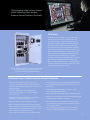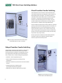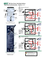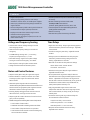
1
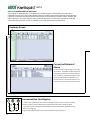
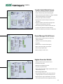
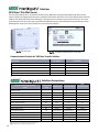
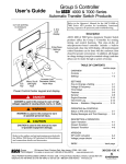
Critical Loads Demand ASCO
ASCO 7000 SERIES
Power Transfer Switches
Protecting:
Healthcare Facilities
Web Hosting, Internet Data Centers
Commercial Buildings / Industrial Buildings
Telecom Central Offices
Process Manufacturing / Wafer Fabrication Plants /
Distributed Power / Load Management
As we become more
dependent on the quality
and reliability of electrical
power, interruption or
complete loss of power can
create serious and even
crippling financial losses, or
impose dangers to life and
safety.
ASCO Power Technologies
(ASCO) provides the solu
tions to handle the transfer
of critical loads to emer
gency sources reliably and
with state of the art prod
ucts. Using ASCO products
can mean the difference
between a minor inconven
ience and a major catastro
phe. You’ll find ASCO Power
Transfer Switches wherever
there is a critical load to be
protected.
2
When flexibility in power
switching is a must, ASCO
offers a variety of product
solutions to meet virtually
every application require
ment, including distributed
generation applications.
That’s why the 7000 SERIES
is available in open, delayed,
closed and closed soft load
configurations. Additionally,
switched or overlapping
neutral options provide for
reliable operation of ground
fault protection systems and
reduction of voltage tran
sients from unbalanced load
switching.
ASCO Power Transfer
Switches are the first CE
Marked, IEC 60947 6 1 com
pliant Transfer Switches in
the world.
The Recognized Leader in Power Transfer
Switch Technology Offers the Most
Advanced Transfer Switches in the World.
7000 SERIES
ASCO Power Transfer Switches are the standard of the
industry. High speed transfer of loads between alter
nate sources of power, regardless of ampacity size, is
achieved by a reliable, field proven solenoid operating
mechanism. When combined with a programmable
microprocessor controller with keypad and LCD display,
they offer the most advanced method of transferring all
types of loads, such as motors, electronic drives, UPS's
and microprocessor based systems. 7000 SERIES Power
Transfer Switches are available open or enclosed, in
ampacity sizes from 30 through 4000 Amperes with the
largest selection of optional accessories offered any
where. All switching configurations are available with an
integrally mounted bypass isolation switch and/or rated
for use in service entrance applications.
Fig. 1: Three Pole 7000 SERIES Automatic Transfer Switch
rated 1600 Amperes (shown with optional front
connected terminals and Power Manager).
7000 SERIES Power Transfer Switches Product Features
• Conventional two position transfer configuration,
plus closed and delayed transition modes of operation.
All configurations available with either automatic or non
automatic control.
• UL listed to 1008 Transfer Switch Equipment &
CSA certified to CSA 22.2 No.178 1978 Automatic
Transfer Switches.
• Qualified and certified to IEC 60947 6 1, CE marked
(optional). (Limited to certain accessories.)
• Rated up to 600 VAC, 30 through 4000 Amperes.
• Reliable and field proven solenoid operating mechanism.
• High withstand and close on ratings including short time
withstand current rating for optimum flexibility in circuit
breaker coordination (600 4000 Amperes).
• Front replaceable main and arcing contacts (800 4000 Amperes).
• Programmable microprocessor controller with keypad and
LCD display.
• Centrally located terminal block for customer control
connections (260 4000 Amperes).
• 16mm, industrial grade control switches and indicating lights.
• Switch position LED indicators and source acceptability lights.
• Standard ground conductor connections.
• Four auxiliary contacts, two contacts closed when switch
is in normal position and two contacts closed when switch
is in emergency position.
• Local/remote communications capability for interfacing
with ASCO POWERQUEST ® communication products.
• Solid, switched, or overlapping neutral conductor options.
3
7000 SERIES Power Switching Solutions
Closed Transition Transfer Switching
ASCO Automatic Closed Transition Transfer Switches feature
main contacts that overlap, permitting the transfer of electrical
loads without power interruption. The switch transfers in a
make before break mode if both sources are within acceptable
parameters. Control logic continuously monitors source
conditions and automatically determines whether the load
transfer should be open (conventional non overlap mode) or
closed transition. Available 150 through 4000 Amperes.
Closed Transition Transfer within 5 electrical degrees is achieved
passively, without control of engine generator set. Therefore, no
additional control wire runs are required between the ATS and
engine generator set governor. Plus, protective relaying may
not be required under normal operation since the contact over
lap time is less than 100 milliseconds (consult your local utility
on protective relay requirements).
Failure to synchronize indication and extended parallel time
protection is built in to all 7000 SERIES closed transition
controls to prevent abnormal operation.
Fig. 2: Four pole, Closed Transition Transfer Switch
rated 1000 Amperes in Type 1 enclosure.
Delayed Transition Transfer Switching
ASCO Delayed Transition Transfer Switches are designed to
provide transfer of loads between power sources with a
timed load disconnect position for an adjustable period of
time. Applications include older style variable frequency
drives, rectifier banks, and load management applications.
• Available in 150 through 4000 Amperes.
• Utilizes reliable, field proven solenoid operating
mechanisms.
• Mechanical interlocks to prevent direct connection of both
sources.
• Indicator light (16mm, industrial grade
type LED) for load disconnect position.
• Adjustable time delay for load disconnect position.
Fig. 3: Four pole, Delayed Transition
Transfer Switch rated 2000 Amperes.
4
7000 SERIES Power Switching Solutions
Non Automatic Transfer Switching
ASCO Non Automatic Transfer Switches are electrically
operated units which are operated with manual control
switches mounted locally or at remote locations.
• Sizes from 30 through 4000 Amperes.
• Microprocessor based controller provides for addition
of optional accessories.
• Controller prevents inadvertent operation under low
voltage conditions.
• Low control circuit operating currents allow for long
line runs between remotely mounted manual control
switches and the transfer switch.
• Source acceptability lights inform operator if sources
are available to accept load.
• Standard inphase monitor can be activated for
transferring motor loads.
Fig. 4: Three pole Non Automatic,
electrically operated 400 ampere switch
shown in Type 1 enclosure.
Withstand and Close On Ratings for all 7000 SERIES Products
5
7000 SERIES Power Switching Solutions
Automatic Transfer Bypass Isolation Switches
Fig. 6: Rated
600 1200 Amps
Fig. 5: Rated
150 600 Amps
ASCO Automatic Transfer & Bypass Isolation Switches are
available in open transition, closed transition and delayed
transition designs. The bypass and isolation features allow
the primary automatic transfer switch to be inspected, tested,
and maintained without any interruption of power to the load.
They also provide redundant power transfer in the event the
ATS is disabled or removed from service.
Fig. 7: Rated
800 3000 Amps
Fig. 8: Rated
4000 Amps
• Transfer switch is drawout design for ease of maintenance.
• Bypass and isolation handles are permanently mounted.
The bypass switch has dead front quick make, quick break
operation for transferring of loads between live sources.
• Bypass switch is fully rated for use as a manual 3 position
transfer switch.
• Bypass and isolation functions are simple, requiring a total
of two operating handles.
• Available 150 to 4000 Amperes.
• Allows bypass isolation without load interruption.
• Bypass switch and transfer switch have identical electrical
ratings.
• Heavy duty mechanical interlocks prevent undesirable
operation.
• Bypass contacts carry current only during bypass mode.
• No toggle switches, push buttons, selector switches or
levers are required for bypass isolation operation.
• Mechanical indicators show bypass and transfer switch
positions.
• 800 1200 ampere available in shallow depth, front
connected or rear connected designs.
Transfer Switch Drawout Features (150 4000 Amperes)
Automatic
Secondary
Disconnects
Automatic
Shutters
(optional on
1600 4000amps)
Fig. 9: Bypass Isolation Transfer
Switch secondary disconnects and
optional automatic shutters.
6
• Automatic secondary disconnects
remove all control power as switch is
withdrawn.
• Drawout carriage provides for easy
transfer switch maintenance and/or
removal via commercially available
breaker hoists.
Self
Aligning
Jaws
• Optional transfer switch lifting yoke
kit available
• Optional automatic shutters which
close when the transfer switch is
withdrawn to provide bus isolation,
specify accessory 82C.(1600 4000A
only)
Fig. 10: Bypass Isolation
Transfer Switch self
aligning power jaws.
7000 SERIES Power Switching Solutions
Bypass and Isolation Handles Simple as 1, 2, 3
LED Indicators
1
Bypass
switch
position
Source
availability
Isolation
handle
position
Transfer
switch
position
Bypass to Normal
Push in bypass
handle and turn
it counter
clockwise
Bypass Handle
*Standard on switches up through H 1200A.
Specify ACC 82E for G frame 1600 4000A
E
L
Isolation Handle
Not in
“auto”
flashing
LED
Fig. 11: Transfer Bypass
Status Panel*
Bypass Switch
N
Automatic Transfer Switch
2
Test Position
Bypass Switch
E
L
Isolation Handle
Mechanical
bypass
switch position
flags
Turn isolation
handle counter
clockwise until
window shows
“Test”
3
N
Automatic Transfer Switch
Isolation Position
Bypass Switch
Isolation
handle
Padlocking
provisions
Mechanical isolation handle position
window (connected/test/isolate)
Fig. 12: Bypass Isolation
Switch user interface
E
L
Isolation Handle
Turn isolation
handle counter
clockwise
until window
shows “Isolate”
N
Automatic Transfer Switch
Key:
Represents Current Flow
In test position control panel remains
energized to allow for electrical
operation of a transfer switch.
7
7000 SERIES Service Entrance Power Transfer Switches
The ASCO Service Entrance Power Transfer Switch
combines automatic power switching with a discon
nect and overcurrent protective device on the utility
source. The power transfer switch meets all National
Electric Code requirements for installation at a facili
ty’s main utility service entrance. Service entrance
rated transfer switches generally are installed at
facilities that have a single utility feed and a single
emergency power source. A circuit breaker serves as
the utility disconnect and links are provided to dis
connect both neutral and ground connections.
This product is either UL 1008 or UL 891 listed and is
available up to 600V and 4000A in Standard, Delayed,
Closed Transition, Soft Load, and Bypass Isolation
Configurations.
Fig. 13: Ground and neutral
disconnect links
Standard Features
• Available from 150 to 4000 Amperes
• ASCO 7000 SERIES Power Transfer Switch is
UL 1008 Listed
• Standard UL Type 1 Enclosure
• Disconnect and overcurrent protective device on
the utility source: molded case circuit breaker 150
to 2000 Amp; insulated case 3000 to 4000 Amp
• Disconnect link on Neutral
• Disconnect link on Ground
• Ground and Neutral Bus, all silver plated copper
• Solderless screw type terminals for External
Power Connections
• Meets all NEC requirements for use as
service entrance
• Internet enabled monitoring and control
• Service entrance breakers rated 100% for 1000
Amps and above; 80% below 1000Amps
Ground Disconnect
Link
Circuit
Breaker
Neutral
Disconnect
Link
Load
Utility
N
Ground Fault
Current
Transformer*
Switched
Neutral
Ø
ATS
GFCT
Ground Fault
Current
Transformer
ATS Automatic Transfer
Switch
Ø
N
Emergency
One line diagram of a typical service entrance rated transfer switch
available in Solid, Switched or Overlapping Neutral
* Ground fault trip protection provided on sizes of 1000 Amperes
and above
Optional Features
• Enclosures
Secure Double Door
UL Type 3R w/strip heater & thermostat
UL Type 4 or 4X
UL Type 12
• Connections
Crimp lugs
Bus Riser on Normal, Emergency or Load
• Protective Relays/Metering
Accessory 85L , see page 15
• Surge Suppression
Accessory 73, Surge protector (see pg. 14)
Communications
•
ASCO 72E Ethernet Connectivity module
ASCO POWERQUEST ® 32.15E, see page 18
ASCO 5500 SERIES Thin Web Server for internet
connection , see page 20
• Additional Breaker(s)
Circuit Breaker on Emergency
Load Distribution Panel
• Optional high AIC ratings on breakers
Consult ASCO for additional features
8
7000 SERIES Service Entrance Power Transfer Switches
Ordering Information
To order an ASCO 7000 SERIES Service Entrance Power Transfer Switch, complete the following catalog number.
7
A
US
+
A
+ 3 + 400
+ N
+ 5X +
C
Neutral
Code*
Product
A
Automatic US
N
Non
UB
Automatic
CUS
CUB
DUS
DUB
Phase
Poles
Conventional 2
A Solid Neutral
Position
(standard)
Open Transition
B Switched
Bypass
Neutral
Closed Transition C Overlapping
Neutral
Closed Transition
Bypass
Delayed Transition
Delayed Transition
Bypass
2
3
Amperes
Voltage
Code
70, 100
150, 200
225, 250
400, 600
800,1000
1200,1600,
2000,2500,
3000
4000
C
D
E
F
H
J
K
L
M
N
P
Q
R
208
220
230
240
380
400
415
440
460
480
550
575
600
Grp
Code
Enclosure
5
C Type 1 enclosure
5X
M Type 3R secure
optional
double door
acces
N
Type
4 secure
sories
double door
P Type 4X secure
double door
(31b SS)
Q Type 12 secure
double door
*Note. Switches rated 150, 600 3000 amps available with 2, 3 or either conventional switched neutral (4 poles) or overlapping neutral (optional). For 4 pole
applications on switches rates 150 to 400 amps (bypass switches only) and 4000 amps specify overlapping switched neutral (optional). Conventional switched neutral
is provided on delayed transition transfer products when specified.
The Example Catalog Number above is 7AUSA3400N5XC (X is used to specify optional accessories).
Dimensions and Weights for non bypass configurations
Type 1 and 3R Enclosures4
Switch Rating Phase Neutral
Poles Code
amps
70, 100 ,150,
200, 225
250, 400
600 , 800
1
1
10001, 12001
16001, 20001
25001, 30001
2
2
3
3
2
2
3
3
2
2
3
3
2
2
3
3
3
3
3
3
STD
B, C
STD
B, C
STD
C
STD
C
STD
B, C
STD
B, C
STD
B, C
STD
B, C
STD
B, C
STD
B, C
Switch Rating Phase Neutral
Poles Code
amps
70, 100 ,150,
200, 225
250, 400
6001, 8001
10001, 12001
16001, 20001
25001, 30001
2
2
3
3
2
2
3
3
2
2
3
3
2
2
3
3
3
3
3
3
STD
B, C
STD
B, C
STD
C
STD
C
STD
B, C
STD
B, C
STD
B, C
STD
B, C
STD
B, C
STD
B, C
Type 1 Dimensions, In. (mm)
Width
Height
Depth
36.5 (927)
36.5 (927)
36.5 (927)
36.5 (927)
36.5 (927)
36.5 (927)
36.5 (927)
36.5 (927)
38 (965)
38 (965)
38 (965)
38 (965)
38 (965)
38 (965)
38 (965)
38 (965)
38 (965)
38 (965)
38 (965)
38 (965)
48.5 (1232)
48.5 (1232)
48.5 (1232)
48.5 (1232)
48.5 (1232)
48.5 (1232)
48.5 (1232)
48.5 (1232)
91 (2311)
91 (2311)
91 (2311)
91 (2311)
91 (2311)
91 (2311)
91 (2311)
91 (2311)
91 (2311)
91 (2311)
91 (2311)
91 (2311)
13.25 (337)
13.25 (337)
13.25 (337)
13.25 (337)
13.25 (337)
13.25 (337)
13.25 (337)
13.25 (337)
28 (711)
28 (711)
28 (711)
28 (711)
48 (1218)
48 (1218)
48 (1218)
48 (1218)
48 (1218)
48 (1218)
72 (1829)
72 (1829)
Type 3R Dimensions, In. (mm)
Width
Height
Depth
36(914)
36(914)
36(914)
36(914)
36(914)
36(914)
36(914)
36(914)
41(1041)
41(1041)
41(1041)
41(1041)
41(1041)
41(1041)
41(1041)
41(1041)
41(1041)
41(1041)
41(1041)
41(1041)
48(1219)
48(1219)
48(1219)
48(1219)
48(1219)
48(1219)
48(1219)
48(1219)
95.5(2426)
95.5(2426)
95.5(2426)
95.5(2426)
95.5(2426)
95.5(2426)
95.5(2426)
95.5(2426)
95.5(2426)
95.5(2426)
96(2438)
96(2438)
16 (406)
16 (406)
16 (406)
16 (406)
16 (406)
16 (406)
16 (406)
16 (406)
34(864)
34(864)
34(864)
34(864)
62(1575)
62(1575)
62(1575)
62(1575)
62(1575)
62(1575)
85(2159)
85(2159)
Approx. Shipping
Weight Lb. (kg)
400 (185)
408 (188)
408 (188)
416 (192)
400 (185)
408 (188)
408 (188)
416 (192)
800 (370)
820 (378)
820 (378)
846 (390)
1085 (501)
1105 (510)
1105 (510)
1134 (523)
2590 (1198)
2640 (1218)
4590 (2118)
4655 (2148)
Approx. Shipping
Weight Lb. (kg)
520 (236)
530 (240)
530 (240)
548 (249)
520 (236)
530 (240)
530 (240)
548 (249)
990 (458)
1010 (467)
1010 (467)
1036 (479)
1305 (604)
1325 (613)
1325 (613)
1354 (626)
2890 (1337)
2940 (1360)
5350 (2474)
5415 (2504)
Ampere Interrupting Capacity
(AIC) Ratings
AIC Rating (kA)
Switch Rating
amps
Standard Optional
70 225
25
35
250
25
35
400
35
35
600, 800
65
N/A
1000,1200
65
N/A
1600, 2000
65
100
2500, 3000
100
N/A
4000
100
N/A
Notes: 1. Unit is designed for top and bottom cable
entry for all services
and load.
2. Enclosures for 600 – 3000 amps are free
standing.
3. When temperatures below 32° F can be
experienced, special precautions should be
taken, such as the inclusion of strip
heaters, to prevent condensation and
freezing of this condensation. This is par
ticularly important when environmental
enclosures (Type 3R, 4 & 12) are ordered
for installation outdoors.
4. Dimensional data is approximate and
subject to change. Certified dimensions
available upon request.
9
7000 SERIES Microprocessor Controller
The 7000 SERIES Microprocessor Based Controller is used with all sizes of Power
Transfer Switches from 30 through 4000 Amperes. It represents the most advanced
digital controller in the industry and includes, as standard, all of the voltage,
frequency, control, timing and diagnostic functions required for most emergency
and standby power applications.
Because of severe voltage transients frequently encountered with industrial
distribution systems, the microprocessor logic board is separated and isolated from
the power board as shown below. This improves electrical noise immunity perform
ance and helps assure compliance with the rigorous transient suppression standards
highlighted below.
Fig. 14: 7000 SERIES
Microprocessor Controller.
Fig.15: Microprocessor Power and Logic PC Boards.
7000 SERIES Microprocessor Based Controller
Emission Standard Group 1, Class A
Generic Immunity Standard, from which:
Electrostatic Discharge (ESD) Immunity
Radiated Electromagnetic Field Immunity
Electrical Fast Transient (EFT) Immunity
Surge Transient Immunity
Conducted Radio Frequency Field Immunity
Voltage Dips, Interruptions and Variations Immunity
10
EN 55011:1991
EN 50082 2:1995
EN 61000 4 2:1995
ENV 50140:1993
EN 61000 4 4:1995
EN 61000 4 5:1995
EN 61000 4 6:1996
EN 61000 4 11:1994
7000 SERIES Microprocessor Controller
Features
• Digital microprocessor.
• Touch pad programming of features and settings
without the need for meters, or variable power supplies.
• Password protection to prevent unauthorized tampering
of settings.
• Sixteen (16) selectable operating voltages available in a
single Controller.
• Remote monitoring and control with ASCO
POWERQUEST ® communications
products. Specify optional accessory 72A or 72E.
• On board diagnostics provide control panel and ATS sta
tus information to analyze system performance.
• Load shed option for bus optimization applications.
Specify optional accessory 30B.
• Displays and counts down active timing functions.
• Historical event log
• Selectable multi language display
(English, German, Portuguese, Spanish, or French. For
others contact ASCO).
• Statistical ATS systems monitoring information
Voltage and Frequency Sensing
Time Delays
• 3 Phase under and over voltage settings on normal
and emergency sources.
• Engine start time delay delays engine starting signal to
override momentary normal source outages adjustable
0 to 6 seconds.
• Under and over frequency settings on normal and
emergency.
• True RMS Voltage Sensing with +/ 1% accuracy;
Frequency Sensing Accuracy is +/ 0.2%.
• Transfer to emergency time delay adjustable 0 to 60
minutes.
• Selectable settings: single or three phase voltage
sensing on normal and emergency; 50 or 60Hz.
• Emergency source stabilization time delay to ignore
momentary transients during initial generator set
loading adjustable 0 to 6 seconds.
• Phase sequence sensing for phase sensitive loads.
• Retransfer to normal time delay with two settings:
• Voltage unbalance detection between phases.
• Power failure mode 0 to 60 minutes.
• Test mode 0 to 10 hours.
Status and Control Features
• Output contact (N/O or N/C) for engine start signals.
• Selection between “commit/no commit” on transfer
to emergency after engine start and normal restores
before transfer.
• Advanced inphase algorithm which automatically
measures the frequency difference between the two sources and
initiates transfer at appropriate phase angles to minimize
disturbances when transferring motor loads.
• Unloaded running time delay for engine cooldown
adjustable 0 to 60 minutes.
• Pre and post transfer signal time delay for selective
load disconnect with a programmable bypass on source
failures adjustable 0 to 5 minutes. This signal can be
used to drive a customer furnished relay, or for (2) sets of
double throw contacts rated 3 amps at 480 volts AC,
specify ASCO optional accessory 31Z.
• Event log displays 99 logged events with the time and
date of the event, event type and event reason.
• Fully programmable engine exerciser with seven
independent routines to exercise the engine generator,
with or without loads, on a daily, weekly, bi weekly or
monthly basis.
• Output signals for remote indication of normal and emer
gency source acceptability
• Contains all alarm signals, logic and time delays for
use with closed transition switches.
• Statistical ATS/System monitoring data screens which provide:
• Insynch time delay 0 to 3 seconds.
• Total number of ATS transfers.
• Failure to synchronize 1 to 5 minutes.
• Number of ATS transfers caused by power source failure.
• Extended parallel 0.1 to 1.0 seconds.
• Total number of days ATS has been in operation.
• Total number of hours that the normal and emergency
sources have been available.
• Delayed transition load disconnect time delay
adjustable 0 to 5 minutes.
11
7000 SERIES User Controls and Indicators
Control Switches and Indicating Lights for Conventional 2 Position Switches
• Switch position indicating lights (16 mm, industrial grade LEDs).
• Source acceptability indicating lights with true indication of the
acceptability of each source, as determined by the voltage, frequency,
voltage unbalance, and phase sequence settings of the control panel
(16mm, industrial grade LEDs).
• Three position (16mm, industrial grade type) selector switch:
• Automatic: Normal maintained position.
• Test: Momentary position to simulate normal source failure for
system test function.
Fig. 16: 7000 SERIES User Controls and Indicators.
• Reset Delay Bypass: Momentary position to bypass transfer and
re transfer time delay.
Control Switches and Indicating Lights for Closed Transition Switches
• Extended Parallel Time Provides visual indication when the
pre set extended parallel time has been exceeded. The controls
automatically open the emergency or normal main contacts.
Separate contact also available to shunt trip external breaker.
• Failure To Synchronize Visually displays a failure to synchronize
alarm if the time delay settings is exceeded, during closed
transition transfer operation.
• TS Locked Out Prevents transfer in either direction if the
extended parallel time is exceeded.
• Alarm Reset Resets extended parallel and failure to
synchronize alarms.
Fig. 17: 7000 SERIES User Controls and Indicators.
• Closed Transition Bypass Pushbutton allows transfer between
sources in an open transition mode.
7000 SERIES Power Control Center
The 7000 SERIES microprocessor controller is a Power Control Center which
allows the user to easily access detailed information on: system status; power
source parameters; voltage, frequency and time delay settings; optional
feature settings; historical event log; and system diagnostics. A four line, (20)
character LCD has a backlit display which enables easy viewing under all
conditions. The user can navigate through all screens using only six buttons,
which also allows selection of: (18) different source parameter settings; (16)
standard time delays; (12) standard feature settings; up to seven independent
engine exercise routines; and even the language (English, German, Spanish,
French, etc.) which appears on the display.
Fig. 18: 7000 SERIES
Power Control Center.
12
Since the Power Control Center must be visible and operable through
the enclosure door, it has been qualified for use in industrial and outdoor
applications. This includes installation in Type 3R (outdoor/rainproof),
4 (weatherproof) and 12 (indoor/industrial) enclosures. For applications with
regular exposure to direct sunlight a double door for UV protection is recom
mended.
7000 SERIES Power Control Center Screens
Status
System Status
Normal OK
Load on Normal
Displays system status in clear, concise language.
Message shown indicates normal source is acceptable
and the load is connected to the normal source.
Source Status
Normal Source
Vab=480V....................ABC
Vbc=480V.........Vunbal=1%
Vca=480V................60.0Hz
Displays voltage for each phase, frequency,
phase rotation and voltage unbalance for both
normal and emergency sources.
Time Delay Status
Inphase Transfer Mode
Normal OK
Emerg OK
TD.Engine.Cooldown:
4min15s
Waiting for In Sync
45o 0.02Hz
Active time delay status displays time
remaining until next control event.
Displays the relative phase angle between
sources and frequency differential to indicate
the controller is awaiting an inphase condition.
Settings
Voltage and Frequency Settings
Time Delay Settings
Normal Voltage
Dropout.............85%.408V
Pickup...............90%.432V
O.V. Trip.........110%.528V
TD N>E Xfer Signal
Bypass if N Fail: No
Pre Xfer: 0 min 20S
Post Xfer: 0 min 20S
Provides voltage and frequency setting values for
normal and emergency sources. Voltage pick up,
dropout and trip settings are set in percentage of nominal
voltage and are also displayed in rms voltage values.
Engine Exerciser
P1..................Engine.Exerciser
Enable:.....Yes....WLoad:....Yes
Start:19h30. ALL MON
Run.Time:...............2h15min
Seven independent programs, load/no load
selection, flexible run times and daily, weekly,
bi weekly and monthly exercise routines.
Provides direct reading display for setting time delays.
Feature Settings
Shed Load
Direction:
Inphase: No
From E
TD/0.25
Standard features can be activated with the keypad. As an
example, when enabled, the “shed load” option causes the
transfer switch to transfer the load off of the specified source.
If desired, the load shed transfer can be made inphase.
Data Logging
ATS Statistics
ATS Statistics
ATS Total Xfers: 46
SRC Fail Tot Xfers: 20
Days Energized: 36.5
Instant availability of statistical information on total number of
ATS transfers, number of transfers caused by power failures and
total days controller has been energized, plus more.
Historical Event Log
16.AUG02/95..........13h10:17
Eng.Start...............NormFail.
15.AUG02/95...........13h10:25
Xfer.N>E................................
Displays detailed information for last 99 events,
including time of occurrence, length of event,
date and reason for event.
13
7000 SERIES Optional Accessories
Time Delays
Neutral Conductor Options
2C
• Solid neutral, with fully rated terminals. (AL CU) UL Listed.
1G
Provides an extended time delay on engine starting.
The standard feature one time delay is adjustable
from zero to six seconds. Accessory 2C allows this
time delay to be adjustable from zero to sixty minutes
in one second intervals factory set at five minutes.
Similar to accessory 2C except using 24 volt DC
external input signal. 7000 SERIES controller remains
active when both power sources are de energized
• Conventional neutral switching pole.
• Overlapping neutral transfer contacts. Allows for proper
ground fault sensing and avoids generator voltage
transients during transfer.
Note: Specify neutral option in catalog number, see page 21 for instructions.
Extension Harness
37B
Six foot (6’) extension harness to increase distance between
transfer switch and control panel on open type units.
Manual Controls for Automatic
Transfer Switches
Analog Load Metering Options
6C
Reset switch for manual retransfer to normal with
automatic retransfer in the event of emergency
source failure.
23B
Three phase ammeter with selector switch
(with current transformers and shorting blocks).
6D
Selector switch for automatic/manual retransfer to
normal. Automatic bypass if emergency fails.
24B
Three phase voltmeter with selector switch.
Engine Generator Controls
and Accessories
12
Three position engine control selector switch.
Positions: 1 Stop 2 Automatic 3 Engine Test
Note: Switches with accessory 12 must be labeled as a non automatic
transfer switch according to UL 1008.
Engine controls containing “engine stop” positions should be located at the engine
generator. (Consult ASCO for application assistance.)
Indicators
14A/14B Additional auxiliary contact sets to indicate switch
position. Two sets are standard. Specify total num
ber of sets if more are required.
Note: Refer to ASCO 5200 SERIES Power Manager on page 15 which provides
voltage, frequency and power monitoring.
Serial Communications
72A
72E
Serial communication module for remote
communications to ASCO POWERQUEST ® products.
Serial to Ethernet converter with
embedded web pages
Surge Protection
ASCO Pulsar 450 rated 65KA
73AC1
73AC2
73AC3
Normal source protection. (3Ø, 4wire WYE)
Emergency source protection. (3Ø, 4wire WYE)
Load side protection. (3Ø, 4wire WYE)
Note: Other distribution voltages available (Contact ASCO).
Special Applications
18B
Two pole, double throw contacts operate when
emergency source voltage is present at transfer
switch terminals.
111A Generator to Generator for Standby Applications
111B Generator to Generator for Prime Power
Applications
18G
Two pole, double throw contacts operate when normal
source voltage is present at transfer switch terminals.
99
“Push to Test” feature on all pilot light indicators.
125 Seismic Certification to the requirements of the
international building code for electrical equipment
131 Certification of compliance with the American
Recovery & Reinvestment ACT (Buy American Provision)
Must be specified at time of order placement
Customer Control Circuits
30A
Load shedding circuit initiated by opening of a
customer supplied contact.
30B*
Load shedding circuit initiated by removal of
customer supplied control voltage. *(Specify voltage).
31Z
Selective load disconnect control contacts (two
provided) which operate with time delay prior to
and/or after load transfer and retransfer.
43R
Terminal block for all customer control connections
on 30 150 amp only (standard on all other sizes).
Note: An externally operable quick make, quick break (QMQB), manual handle is avail
able on some 7000 SERIES product configurations. (Consult ASCO for guidance.)
Bypass Isolation Switch Options
14A1
Auxiliary contact to close in “Bypass to Normal”
position.
14B1
Auxiliary contact to close in “Bypass to Emergency” position.
14T
Auxiliary contact to close when transfer switch is in
“Automatic” position.
14U
Auxiliary contact to close when transfer switch is in
“Isolate” position.
14V
82C
82 E
14
Auxiliary; contact to close when transfer switch is in
“Test” position.
Automatic shutters for bus isolation when transfer
switch is withdrawn. (see page 6 for details)
LED Bypass status indicator, optional on G frame
1600A 4000A only. Standard for all other size switches
7000 SERIES Optional Accessories
ASCO 5200 SERIES
Power Manager
POWER SYSTEM TOTAL
404 KW
+1.00 PF
0 KVAR
60.00 Hz
404 KVAATSºn NORM
The ASCO 5200 SERIES Power Manager is a microprocessor
based metering device that provides real time measure
ments of single and three phase power systems. The
Power Manager uses digital signal processing technology
to measure voltage and current per phase; real, reactive
and apparent power, and bi directional energy. All meas
urements can be viewed locally with a backlit liquid crystal
display and/or displayed remotely with ASCO
POWERQUEST ® products.
Direct voltage input for systems up to 600 Volts AC
can be monitored without the use of external potential
transformers (PTs). Measures three phase currents and a
fourth current input is available for measuring current
in the neutral conductor. The Power Manager includes
one discrete input for transfer switch position, eight
general purpose discrete inputs, and four relay outputs
for monitoring and controlling external devices.
Fig. 19: ASCO 5200 SERIES Power Manager.
Configurable Designations
• Local A four line, 20 character LCD backlit display.
• Remote Integrated 4 wire RS485 port; optional 5110 Serial
Module (72A) or 5150 Communications Module (72E) and
power manager monitoring systems.
• Frequency: 45.0 to 66.0 Hertz
• Provides user programmable setpoints based on twelve meter
ing and I/O parameters. Each setpoint allows the user to select
the parameter, the trip & reset levels, the trip & reset time
delays and the alarm type or relay output to trigger. This can be
used for protective relaying and peak shaving applications.
• 100 event data logging feature.
• Current: IA, IB, IC, IAVERAGE
Integrated ATS Features
• Unbalance %: Voltage, Amps
When configured on load of ATS:
Power Metering
• Voltage:
Line Line: VAB, VBC, VCA, VAVERAGE
Line Neutral: VAN, VBN, VCN, VAVERAGE
• Real Power: KWA, KWB, KWC, KWNET
• Displays ATS position.
• Reactive Power: KVARA, KVARB, KVARC, KVARNET
• Displays power data as a function of ATS position
(normal/emergency).
• Apparent Power: KVAA, KVAB, KVAC, KVANET
• Real Energy: KWHIMPORT, KWHEXPORT, KWHNET
• Reactive Energy: KVARHIMPORT, KVARHEXPORT,
KVARHNET
• Power Factor: PFA, PFB, PFC, PFNET
Data Access
• Eight digital inputs, four relay outputs.
• Input/Output 15 character, user definable screen
display for identification of input/output signals.
Communications
• Accumulates energy data separately for normal and
emergency sources.
Optional Configurations and
Connection Arrangements
Connected To:
Load
Normal
Emergency
Load (BPS only)
With Display
Acc. 85L
Acc. 85N
Acc. 85M
Acc. 85R*
Without Display
Acc. 75L
Acc. 75N
Acc. 75M
Acc. 75R*
• RS485 (2) or (4) wire serial capability.
Add suffix “A” to above designations if neutral conductor monitoring is required.
• Includes Modbus RTU.
Note: Accessory 75 and 85 includes component mounting, CTs, shorting
blocks and all necessary interwiring.
• Ethernet compatible when combined with
5150 Connectivity Module (72E).
*Bypass & isolation switch contacts wired to discrete Power Manager
inputs.
Note: The ASCO Power Manager is also available as a separate unit for monitoring electrical parameters anywhere in the power distribution system.
15
7000 SERIES Power Monitoring & Control
ASCO POWERQUEST Solutions
ASCO POWERQUEST ® communications products allow for the monitoring and control of power transfer
switches in your Emergency or Standby Power Distribution System. Local Area networks and Remote networks
are supported with either single or multiple points of access, and web enabled communications allow access
to your power system from anywhere around the world.
Features
• Monitors and controls Power Transfer Switches and Engine Generators
• Monitors normal and emergency voltages and frequency
• Indicates transfer switch position and source availability
• Provides transfer and re transfer of loads for system testing
• View normal and emergency voltage and frequency settings
• View transfer switch time delay settings
• Provides transfer switch rating and identification
• Automatic paging notifies personnel, by e mail or text message, of selected system alarms
• View current, power and power factor with ASCO Power Managers Connected to the System
• View transfer switch event log
• Provides transfer switch test schedule
Typical Network Architecture
ASCO 5110 (72A) Serial Modules
RS 485
ASCO 5150 (72E)
Connectivity Module
ASCO 5200
Power Manager
To Additional
Automatic
Transfer
Switches
Generator 1
ASCO
ATS 1
Ethernet
Switch
ASCO
POWERQUEST ®
32.15 Software
ASCO
ATS 2
ASCO 5110 (72A) Serial Modules
RS 485
ASCO 5150
(72E)
Connectivity
Module
ASCO 5200
Power Manager
To Additional
Automatic
Transfer
Switches
Generator 2
ASCO
ATS 3
16
ASCO
ATS 4
7000 SERIES Power Monitoring
5110 Serial Module
The 5110 Serial Module is used to allow local or remote communications with ASCO
POWERQUEST ® communication products.
The module is used to connect the 7000 SERIES transfer switches to a serial network
via an RS 485 interface. The module has two port connectors used for ATS & Power
Manager connectivity.
The serial connection is accomplished from a 5 pin terminal header/socket block.
RS 485 serial networks allow for up to 32 modules to be set up in a daisy chain
configuration to connect to POWERQUEST ® systems.
Fig. 20: Serial
Module 72A
5150 Connectivity Module
Fig. 21: Connectivity
Module 72E
The 5150 Connectivity Module is used to bring several different serial devices that
communicate at different baud rates and with different protocols to a common
Ethernet media.
The module is used to connect 7000 SERIES transfer switches, and ASCO Remote
Annuciators to a standard Ethernet TCP/IP network with standard 10base T(RJ 45)
connectors. The module has customized embedded JAVATM applets (program
applications for an internet browser) for each monitored device that loads
automatically to a standard Web Browser.
The module is designed to communicate with up to 8 clients such as Web
applications (web pages), POWERQUEST ® , or third party Modbus® devices
simultaneously over an Ethernet connection.
5350 Remote Annunciator
Fig. 22: ASCO
Remote Annuciator
The ASCO Power Transfer Switch Remote Annunciator is a stand alone, industrial
grade interface device providing you with the most critical transfer switch status
indication and transfer/retransfer control for up to eight switches. Ethernet
technology is built in for faster and more reliable communications. LEDs
indicate switch status and position, while separate push buttons individually initiate
transfer switch operation and testing. Transfer switch annunciators can be set up in
multiple locations to monitor various transfer switches, allowing redundant and
distributed annunciation.
Accessory 113S
Accessory 113S is an advanced power quality and energy meter providing intelligent
power analysis, energy measurement and event recording for critical and
sensitive loads. It improves response to power quality related issues by
continuously monitoring and recording harmonics, sags/swells and disturbances.
Power uptime is captured, computed and displayed in a simple number of 9s format.
A large built in LCD display allows viewing of all parameters locally or remotely over
Ethernet (Acc. 113SE).
Fig. 23: ASCO Power Quality and
Energy Meter
On board memory stores up to 500 events, 1.5 years of data, and 360 waveforms at
a sampling rate of 1024 samples per cycle or 1 ms timestamp resolution.
17
32.15
ASCO 32.15 POWER INTERFACE SOFTWARE
The ASCO 32.15 Power Interface is a computer based monitoring and control software package. When
combined with ASCO 72E/72A Communications Interface modules and the ASCO 5200 SERIES Power Manager,
it provides a centralized and comprehensive monitoring and control interface of power transfer switches and
engine generators. A one line diagram, power metering information, transfer switch controls and event log
data, and engine generator screens are available to users with password protected controls.
Summary Screen
Current and Historical
Alarms
The Current Alarm screen displays all currently
active alarms. It provides the date of the alarm,
along with IP and Name of the device with the
issue. In addition, a detailed description of the
alarm is provided to help the operator in pin
pointing the issue. All historical alarms can be
viewed as well by selecting the “Historical” tab.
L
E
E
N
N
Convenient One Line Diagram
• Colored icons highlighted to show source availability and which source is connected to load.
• Contacts move on icon to indicate main contact position of transfer and bypass switch.
(Automatic transfer and bypass isolation switches must be provided with optional accessory
85R seen on page 15.)
• Bypass switch contacts appear on icon when configured by user input data.
18
32.15
Transfer Switch Detail Screen
• ATS rating and identification data is displayed.
• Allows remote testing and time delay bypass.
• Voltage, frequency, phase sequence, voltage unbalance
and time delay settings can be checked.
• Viewing of engine exercise schedules.
• Displays phase to phase voltage on normal and
emergency.
• Provides complete system status message from
7000 series microprocessor controller.
• View event log on the last 99 events for each ATS.
• Arrange test schedules for transfer switches.
• Provides for monitoring of local site or remote sites.
Power Manager Detail Screen
• Voltage: phase to phase; phase to neutral and
voltage unbalance.
• 3 phase currents and neutral (optional).
• Frequency.
• Kilowatt hours normal and emergency.
• Status and control of four relay outputs.
• Status of eight digital inputs.
• Device ratings: CT and PT ratio.
Engine Generator Details
• Voltage: Phase to phase; Phase to neutral
• Current for each phase.
• Kilowatts and kilowatt hours total.
• Frequency and power factor.
• Status and control of four digital outputs which can be
customized by the user.
• Status of eight digital inputs.
• “Alarm Enabled” selection. These alarms flash the
“engine generator” icon on the summary screen.
• Digital inputs for engine malfunctions are derived
from engine mounted sensors (supplied by others).
19
Solutions
5500 SERIES Thin Web Server
The ASCO Thin Web Server is an internet based thin client application, which provides monitoring and control of
transfer switches and engine generators from anywhere in the world. With ASCO 72E/72A Communications Interface
modules and ASCO 5200 SERIES Power Managers, it brings the power interface to your browser with your user name
and password. Alarms and event logs are provided through the browser, while simultaneously transmitting an email
indicating that an alarm has occurred with one or more transfer switches.
Fig. 24: Thin Web Server
Fig. 25: Thin Web's html interface screen shot
Communications Products for 7000 SERIES Transfer Switches
Description
Acc. Option
Catalog No.
Serial Module
72A
5110
Connectivity Module
72E
5150
Power Manager with Display*
85L
5220D
Thin Web Server*
—
5510E
Software Package*
—
32.15
* These products are available as separate items only. They can be ordered by catalog numbers shown in above chart.
Solutions Comparison
ASCO Connectivity Solution Guide
Feature
Quantity of Monitored / Controlled Power Transfer
Switches per LAN
32.15
32
5500
5350
5150
Thin Web Server Connectivity Module Remote Annunciator
64
1024+
8
4
8
1024+
0
Control & Monitoring Capability
Yes
Yes
No
Yes
Embedded Web Pages
No
Yes
Yes
Yes
Ethernet Network Compatible
Yes
Yes
Yes
Yes
Monitor Multiple Protocols & Baud Rates
(ASCO I, ASCO II, Modbus)
No
No
Yes
Yes
Intranet
Internet
Intranet
Intranet
Number of Monitored / Controlled Gensets
Monitor Multiple Sites
Multiple Client Access
No
Up to 8
Up to 8
Up to 8
Client Software Required
Yes
Internet Explorer
Internet Explorer
Internet Explorer*
Monitors Dissimilar ASCO Controllers on Common LAN
No
No
Yes
Yes
Communicates with ASCO Remote Annuciators
No
No
Yes
Yes
Email / Paging Alarms
No
Yes
No
No
No
Yes**
Historical Trending Option Alarms
* Internet Explorer only required for initial communications setup.
** Historical trending not available on Remote Annuciator.
20
POWERQUEST ®
No
Yes
Solutions
Remote
Access
Computer
Local
Computer
Ethernet
RS 485
Ethernet Switch
Internet
Firewall
Pager
ASCO 5500
Thin Web
Server
Email Server
Ethernet
Monitoring
and Control
ATS Annunciator
Modbus/RTU
RS 485
Building
Management
Computer
ASCO
Digital Paralleling
System
Ethernet Switch
ASCO
5110 (72A)
Serial
Modules
ASCO
5150 (72E)
Connectivity
Modules
To Additional
Automatic
Transfer
Switches
ASCO
ATS 1
ASCO
ATS 2
To Additional
Automatic
Transfer
Switches
ASCO
ATS 1
ASCO
ATS 2
21
7000 SERIES Ordering Information
To order an ASCO 7000 SERIES Power Transfer Switch, complete the following catalog number:
7
A
TS
A
+
Neutral
Code*
Product
A
N
Automatic
Non
Automatic
TS
Conventional
2 Position
TB
Open
Transition
Bypass
CTS
Closed
Transition
CTB
M
Manually
Operated
Closed
Transition
Bypass
DTS
Delayed
Transition
DTB
Delayed
Transition
Bypass
3
+
B
C
400
Amperes
2
3
30
70
100
150
200*
230 *
260
400
600
800
1000
1200
1600
2000
2600
3000
4000
Solid Neutral
Switched
Neutral
Overlapping
Neutral
N
+ 5X +
C
Voltage
Code
Grp
Code
Enclosure
+
Phase
Poles
No Neutral
A
+
A
B
C
D
E
F
H
J
K
L
M
N
P
Q
R
115
120
208
220
230
240
380
400
415
440
460
480
550
575
600
5
5X
optional
acces
sories
No enclosure
C
Type 1 enclosure
F
Type 3R
enclosure
G
Type 4 enclosure
H
Type 4X
enclosure
(stainless steel)
L
Type 12
enclosure
M
Type 3R secure
double door
N
Type 4 secure
double door
P
Type 4X secure
double door
Q
Type 12 secure
double door
R
Type 3RX secure
double door
(Stainless Steel)
*Notes: Conventional switch neutral is provided on delayed transition transfer products when specified.
200 and 230 amp switch limited to 480 volts maximum, on 7ATS, 7CTS and 7DTS only.
The Example Catalog Number above is 7ATSA3400N5XC
(X is used to specify optional accessories).
Transfer Switch Configurations
Transfer/Bypass Configurations
7A TS, 7N TS, 7A DTS, 7A CTS, 7N DTS, 7N CTS
7A TB, 7N TB, 7A DTB, 7A CTB, 7N DTB, 7N CTB
Sizes of UL Listed Solderless Screw Type
Terminals for External Power Connections
Sizes of UL Listed Solderless Screw Type
Terminal for Power Connections
Switch Rating
amps
Max # of Conductors
per Terminal
Range of AL CU
Conductor Sizes
Switch Rating
amps
Max # of Conductors
per Terminal
Range of AL CU
Conductor Sizes
30 2303
One
#14 to 4/0 AWG
One
# 4 AWG to 600 MCM
260 400
One
#4 AWG to 600 MCM
150, 200, 230
260,400
Two
# 1/0 AWG to 250 MCM
Two
#1/0 AWG to 250 MCM
6004
Two
# 2 AWG to 600 MCM
600
Two
#1/0 AWG to 600 MCM
800,1000,1200
Four
# 1/0 AWG to 600 MCM
800 12001
Four
#1/0 AWG to 600 MCM
1600 20004
Six
# 1/0 AWG to 600 MCM
#1/0 AWG to 600 MCM
2600, 30004
Ten
# 2 AWG to 600 MCM
Twelve
#1/0 AWG to 600 MCM
4000
Twelve
# 2 AWG to 600 MCM
Twelve
#2/0 AWG to 600 MCM
1600 2000
2
2600, 3000
4000
2
2
Six
Notes: 1. Unit is designed for top cable entry of emergency and load and bottom entry of
normal. Optionally, the switch may be supplied with reverse source and/or bot
tom entry load, when specified.
2. All main terminals are rear connected.
22
4
4
3. 200 and 230 amp rating for copper conductors only for transfer switch
configurations only.
4. All main terminals are rear connected. A front connected version is
available in 600 and 1200 amp ratings only with top cable entry only.
See pages 25-27 for dimensional data and additional information.
5.Type 304 stainless steel standard. Specify 316 ST. Steel for installations
subject to salt water and corrosive environments
7000 SERIES Designed to Fit Anywhere*
2 Position Transfer Switching 7A TS, 7N TS (Non Bypass)
Switch Rating
Amps
Poles
Width
Height
Depth
inches (mm) inches (mm) inches (mm)
Enclosed UL Type 1 2
30, 70, 100, 125, 150, 200, 230 2, 3 or 3 with neutral A/B/C
260, 400
600
2, 3 or 3 with neutral A/B/C
2, 3 or 3 with neutral A/B/C
18 (457)
48 (1219)
13 (330)
24 (610)
24 (610)
56 (1422)
63 (1600)
14 (356)
17 (432)
800, 1000
2, 3 or 3 with neutral A/B/C
34 (864)
72 (1829)
20 (508)
1200
1600, 2000 1
2, 3 or 3 with neutral A/B/C
2, 3 or 3 with neutral A/B/C
38 (965)
38 (965)
87 (2210)
91 (2311)
23 (584)
48 (1219)
1600, 20003 (front connected)
2, 3 or 3 with neutral A/B/C
38 (965)
87 (2210)
23 (584)
2600, 3000 1
2, 3 or 3 with neutral A/B/C
38 (965)
91 (2311)
60 (1524)
2, 3 or 3 with neutral A/C
60 (1524)
91 (2311)
72 (1829)
2, 3 or 3 with neutral B/C
10 1/4 (260)
10 1/4 (260)
5 1/2 (140)
2, 3 or 3 with neutral B/C
2, 3 or 3 with neutral B/C
2, 3 or 3 with neutral B/C
2, 3 or 3 with neutral B/C
18 1/2 (470)
19 (483)
27 (686)
33 1/4 (845)
25 (635)
30 (762)
31 (787)
28 (711)
8 (203)
9 7/8 (251)
12 7/8 (327)
26 1/4 (667)
2600, 3000
2, 3 or 3 with neutral B/C
33 1/4 (845)
28 (711)
30 3/4 (781)
4000
2, 3 or 3 with neutral C
70 (1778)
53 (1272)
4000 1
Notes:
1. Enclosures are free standing
with removable top, sides, and
back.
2. Consult ASCO for dimensions on
enclosures other than UL type 1.
3. Order accessory 40MY for
1600A and 40NY for 2000A F/C
design.
* All dimensions and weights
shown are approximate and should
not be used for construction
purposes. Certified dimensions can
be furnished upon request.
Open Configuration
30, 70, 100, 125,150, 200, 230
260, 400
600
800, 1000, 1200
1600, 2000
60 (1524)
Shipping Weights
2 Position Transfer Switching 7A TS, 7N TS
Switch Rating
Amps
Poles
2
Enclosed*
lb (kg)
Open*
lb (kg)
30, 70, 100, 125
30, 70, 100, 125
30, 70, 100, 125
150, 200, 230
150, 200, 230
150, 200, 230
260, 400
260, 400
260, 400
600
600
600
3
3 with B/C
2
3
3 with B/C
2
3
3 with B/C
2
3
3 with B/C
67 (31)
70 (32)
73 (33)
69 (32)
72 (33)
75 (34)
216 (98)
223 (101)
230 (105)
316 (143)
324 (147)
332 (151)
15 (7)
18 (8)
21 (10)
17 (8)
20 (9)
23 (11)
82 (37)
89 (40)
102 (46)
88 (40)
96 (44)
104 (47)
800, 1000
800, 1000
800, 1000
1200
2
3
3 with B/C
2
400 (182)
420 (192)
446 (203)
685 (312)
150 (68)
170 (78)
196 (90)
150 (68)
1200
1200
1600, 2000
1600, 2000
3
3 with B/C
2
3
705 (321)
731 (333)
1110 (503)
1160 (525)
170 (78)
196 (90)
370 (167)
420 (190)
1600, 2000
2600, 3000
2600, 3000
2600, 3000
3 with B/C
2
3
3 with B/C
1210 (548)
1365 (620)
1430 (649)
1495 (679)
470 (213)
405 (184)
470 (213)
535 (243)
4000
4000
4000
2
3
3 with B/C
1969 (893)
2149 (975)
2328 (1056)
1258 (571)
1451 (658)
1623 (736)
* All dimensions and weights
shown are approximate and should
not be used for construction
purposes. Certified dimensions can
be furnished upon request.
23
7000 SERIES Designed to Fit Anywhere*
Closed Transition and Delayed Transition Transfer Switching
7A DTS, 7A CTS, 7N DTS, 7N CTS
Switch Rating
Amps
Poles
Width
inches (mm)
Height
Depth
inches (mm) inches (mm)
150, 260, 400
2, 3 or 3 with neutral A/B
24 (610)
56 (1422)
14 (356)
600
800, 1000
2, 3 or 3 with neutral A/B
2, 3 or 3 with neutral A/B
24(610)
34 (864)
63 (1600)
72 (1829)
17(432)
20 (508)
1200
1600, 2000 1
2, 3 or 3 with neutral A/B
2, 3 or 3 with neutral A/B
38 (965)
38 (965)
87 (2210)
91 (2311)
23 (584)
48 (1219)
1600, 20003 (front connected)
3000 1
2, 3 or 3 with neutral A/B
2, 3 or 3 with neutral A/B
38 (965)
38 (965)
87 (2210)
91 (2311)
23 (584)
60 (1524)
4000 1
2, 3 or 3 with neutral A/C
60 (1524)
91 (2311)
72 (1829)
150, 260, 400
2, 3 or 3 with neutral B
18 1/2 (470)
25 (635)
8 (203)
600
800, 1000, 1200
1600, 2000
2600, 3000
4000
2, 3 or 3 with neutral B
2, 3 or 3 with neutral B
2, 3 or 3 with neutral B
2, 3 or 3 with neutral B
2, 3 or 3 with neutral C
19 (483)
27 (686)
33 1/4 (845)
33 1/4 (845)
60 (1524)
30 (762)
31 (787)
28 (711)
28 (711)
70 (1778)
9 7/8 (251)
12 7/8 (327)
26 1/4 (667)
30 3/4 (781)
53 (1272)
Enclosed UL Type 1 2
Open Configuration
Notes:
1. Enclosures are free
standing with removable top,
sides, and back.
2. Consult ASCO for dimen
sions on enclosures other
than UL type 1.
3. Order accessory 40MY for
1600A and 40NY for 2000A
front connected design.
* All dimensions and weights
shown are approximate and
should not be used for
construction purposes.
Certified dimensions can be
furnished upon request.
Shipping Weights
Closed Transition and Delayed Transition Transfer Switching
7A DTS, 7A CTS, 7N DTS, 7N CTS
24
Switch Rating
Amps
Poles
Enclosed*
lb (kg)
Open*
lb (kg)
150, 260, 400
150, 260, 400
150, 260, 400
600
600
600
800, 1000
800, 1000
800, 1000
1200
1200
1200
1600, 2000
1600, 2000
1600, 2000
2600, 3000
2600, 3000
2600, 3000
4000
4000
4000
2
3
3 with B
2
3
3 with B
2
3
3 with B
2
3
3 with B
2
3
3 with B
2
3
3 with B
2
3
3 with B/C
235 (107)
242 (110)
250 (113)
335 (152)
343 (156)
352 (159)
420 (192)
450 (205)
480 (219)
710 (324)
740 (337)
770 (351)
1300 (590)
1350 (612)
1400 (635)
1555 (706)
1620 (735)
1685 (765)
1969 (893)
2149 (975)
2328 (1056)
101 (46)
108 (49)
115 (52)
107 (48)
115 (52)
124(56)
175 (80)
205 (94)
235 (108)
175 (80)
205 (94)
235 (108)
505 (229)
555 (252)
605 (274)
540 (245)
660 (300)
725 (329)
1258 (571)
1451 (658)
1623 (736)
Notes:
1. Open weights include
transfer switch and control
panel. 1200 4000 amp enclo
sures require ventilation open
ings, refer to drawings for
details. Export shipments may
require a wooden box, contact
ASCO for weights and
dimensions.
* All dimensions and weights
shown are approximate and
should not be used for
construction purposes.
Certified dimensions can be
furnished upon request.
7000 SERIES Designed to Fit Anywhere*
Automatic Transfer Bypass Isolation Switching
with Transfer Switch Engaged 7A TB, 7N TB
Switch Rating
amps
Power Connection
Configuration
Width
Height
Depth
inches (mm) inches (mm) inches (mm)
Poles
Enclosed UL Type 1
150, 200, 230, 260, 4001, 600
800 1, 3
Front Connected
Front Connected
2, 3 or 3 with neutral A/B/C
2, 3 or 3 with neutral A/B/C
34 (864)
38 (965)
85 (2159)
91 (2311)
28 (711)
32 (813)
1000, 1200
800, 1000, 12001, 2
Front Connected
Side/Rear Connected
2, 3 or 3 with neutral A/B/C
2, 3 or 3 with neutral A/B/C
38 (965)
38 (965)
91 (2311)
91 (2311)
34 (864)
48 (1219)
1600, 20001,2
2600, 30001, 2
Side/Rear Connected
Side/Rear Connected
2, 3 or 3 with neutral A/B/C
3 or 3 with neutral A/B/C
38 (965)
38 (965)
91 (2311)
91 (2311)
60 (1524)
72 (1829)
40001,2
Rear Connected
3 or 3 with neutral A/C
60(1524)
91 (2311)
96 (2438)
150, 200, 230, 260, 4001
Front Connected
2, 3 or 3 with neutral B/C
19 3/4 (500)4
61 1/2 (1553)4
22 1/4 (565)4
600, 800, 1000, 1200
1600, 2000, 2600, 30001, 2
40001,2
Rear Connected
Rear Connected
Rear Connected
2, 3 or 3 with neutral B/C
2, 3 or 3 with neutral B/C
3 or 3 with neutral A/C
38 (965)
38 (965)
60(1524)
72 (1829)
72 (1829)
91 (2311)
38 (965)
38 (965)
96 (2438)
Open Configuration
1, 2
Notes: 1. Handles extend 6 1/4 inches (159mm).
2. Recommended clearance to enclosure: 3 feet (914mm) from rear, 4 feet (1219mm) from front (25 inches required for transfer switch drawout).
Side or rear access required.
3. Specify optional accessory 40J Y for 800 Amp front, 40KY for 1000 Amp, and 40LY for 1200 Amp connected arrangement. All service and load
cables limited to top entry only.
4. Contact ASCO for details.
* All dimensions and weights shown are approximate and should not be used for construction purposes.
Certified dimensions can be furnished upon request.
Shipping Weights
Automatic Transfer Bypass Isolation Switching
with Transfer Switch Engaged 7A TB, 7N TB
Switch Rating
amps
Poles
Enclosed*
lb (kg)
Open*
lb (kg)
150, 200, 230, 260, 400, 600
150, 200, 230, 260, 400, 600
150, 200, 230, 260, 400, 600
2
3
3 with B/C
990 (450)
1050 (477)
1110 (505)
Contact ASCO
Contact ASCO
Contact ASCO
800, 1000, 1200
800, 1000, 1200
800, 1000, 1200
1600, 2000
2
3
3 with B/C
2
1510 (685)
1580 (717)
1650 (748)
2180 (989)
920 (417)
990 (449)
1060 (481)
1300 (589)
1600, 2000
1600, 2000
2600, 3000
2600, 3000
3
3 with B/C
3
3 with B/C
2360 (1070)
2540 (1152)
2730 (1240)
3360 (1525)
1550 (702)
1800 (815)
1690 (768)
1980 (899)
4000
4000
3
3 with B/C
6300 (2858)
6900 (3130)
–
–
Notes: 1.Open weights include transfer switch, bypass isolation switch and controller.
1600 4000 amp enclosures require ventilation openings, refer to drawings for details.
Export shipments may require a wooden box, contact ASCO for weights and dimensions.
* All dimensions and weights shown are approximate and should not be used for construction purposes.
Certified dimensions can be furnished upon request.
25
7000 SERIES Designed to Fit Anywhere*
Automatic Transfer Bypass Isolation in Closed Transition and Delayed
Transition Switching. 7A DTB6, 7A CTB, 7N DTB6, 7N CTB
Switch Rating
amps
Power Connection
Configuration
Depth
Width
Height
Depth
inches
(mm)
inches (mm) inches (mm) inches
(mm)
Poles
Enclosed UL Type 1
150, 200, 230, 260, 4001, 600
800 1, 3
Front Connected
Front Connected
2, 3 or 3 with neutral A/B/C
2, 3 or 3 with neutral A/B/C
34 (864)
38 (965)
85 (2159)
91 (2311)
28 (711)
32 (813)
1000, 1200
800, 1000, 12001, 2
Front Connected
Side/Rear Connected
2, 3 or 3 with neutral A/B/C
2, 3 or 3 with neutral A/B/C
38 (965)
38 (965)
91 (2311)
91 (2311)
34 (864)
48 (1219)
1600, 20001,2
2600, 30001, 2
Side/Rear Connected
Side/Rear Connected
2, 3 or 3 with neutral A/B/C
3 or 3 with neutral A/B/C
38 (965)
38 (965)
91 (2311)
91 (2311)
60 (1524)
72 (1829)
40001,2
Rear Connected
3 or 3 with neutral A/C
60(1524)
91 (2311)
96 (2438)
Front Connected
Rear Connected
Rear Connected
Rear Connected
2, 3 or 3 with neutral B/C
2, 3 or 3 with neutral B/C
2, 3 or 3 with neutral B/C
3 or 3 with neutral A/C
61 1/2 (1553)4
72 (1829)
72 (1829)
91 (2311)
22 1/4 (565)4
38 (965)
38 (965)
96 (2438)
Open Configuration
150, 200, 230, 260, 4001
600, 800, 1000, 12001, 2
1600, 2000, 2600, 30001, 2
40001,2
19 3/4 (500)4
38 (965)
38 (965)
60(1524)
Notes: 1. Handles extend 6 1/4 inches (159mm).
2. Recommended clearance to enclosure: 3 feet (914mm) from rear, 4 feet (1219mm) from front (25 inches required for transfer switch drawout).
Side or rear access required.
3. Specify optional accessory 40J Y for 800 Amp front, 40KY for 1000 Amp, and 40LY for 1200 Amp connected arrangement. All service and load
cables limited to top entry only.
4. Contact ASCO for details.
* All dimensions and weights shown are approximate and should not be used for construction purposes.
Certified dimensions can be furnished upon request.
Shipping Weights
Automatic Transfer Bypass Isolation in Closed Transition and Delayed
Transition Switching. 7A DTB, 7A CTB, 7N DTB, 7N CTB
Switch Rating
amps
Poles
Enclosed*
lb (kg)
Open*
lb (kg)
150, 200, 230, 260, 400, 600
150, 200, 230, 260, 400, 600
150, 200, 230, 260, 400, 600
800, 1000, 1200
800, 1000, 1200
800, 1000, 1200
1600, 2000
1600, 2000
1600, 2000
2600, 3000
2600, 3000
2
3
3 with A/B
2
3
3 with A/B
2
3
3 with A/B
3
3 with A/B
990 (450)
1050 (477)
1110 (505)
1560 (708)
1630 (739)
1700(771)
2315 (1050)
2495 (1132)
2675 (1213)
2730 (1240)
3360 (1525)
Contact ASCO
Contact ASCO
Contact ASCO
970 (440)
1040 (472)
1110(503)
1435 (651)
1685 (764)
1935 (878)
1690 (768)
1980 (899)
4000
4000
3
3 with C
6300 (2858)
6900 (3130)
–
–
Notes: 1. Open weights include transfer switch, bypass isolation switch and controller.
1600 4000 amp enclosures require ventilation openings, refer to drawings for details.
Export shipments may require a wooden box, contact ASCO for weights and dimensions.
* All dimensions and weights shown are approximate and should not be used for construction purposes.
Certified dimensions can be furnished upon request.
26
7000 SERIES Designed to Fit Anywhere*
Optional Front Connected Design Saves Valuable Space
Cable
Compartment
800 Amp Optional Front Connected Design
32.00
Ground Bus
Load Lugs
17.00
Normal Lugs
Field Wiring
Terminal Block
(TB)
Bypass
Switch
Manual
Operation
Handle
Emergency Lugs
Bypass Handle
38.76
Isolation
Handle
Group 5
Controller
User
Interface
91.00
Controls and
Indication
* All dimensions and weights
59.05
REF
Isolation
Handle
Transfer Switch
Compartment
35.24
shown are approximate and
should not be used for con
struction purposes. Certified
dimensions can be furnished
upon request.
12.42 REF
39.00
CG
Front Views (Covers Installed)
Right Side Views (Covers Removed)
1000 1200 Amp Optional Front Connected Design
38.00
34.00
Cable Access
Hinge Cover
Ground Bus
Field Wiring
Terminal Block
(TB)
Emergency Lugs
Load Lugs
Normal Lugs
Bypass Switch
Manual Operation
Handle
Group 5
Controller
User
Interface
91.00
6.22
REF
Isolation Handle
Controls and
Indication
59.05
REF
Isolation
Handle
Transfer Switch
Compartment
27
A SCO Power Te ch nologies
50 Ha nover Road
F l o r ha m Pa r k , N J 0 7 9 3 2
USA
8 0 0 8 0 0 A SCO
www.ascopower.com
www.ascoapu.com
Emerson Network Power.
The global leader in enabling Business-Critical ContinuityTM.
EmersonNetworkPower.com
Outside Plant
AC Power
Connectivity
Embedded Computing
Embedded Power
DC Power
Infrastructure Management & Monitoring
Power Switching & Controls
Precision Cooling
Racks & Integrated Cabinets
Services
Surge Protection
Emerson Network Power and the Emerson Network Power logo are trademarks and service marks of Emerson Electric Co. ©2010 Emerson Electric Co.
Publication 3040 R12
© April, 2010
Printed in the U.S.A.