1
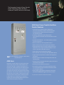
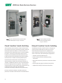
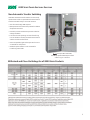
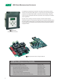
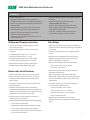
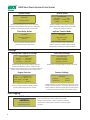
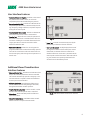
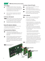
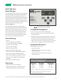
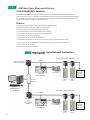
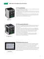
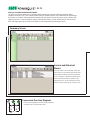
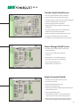
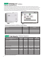
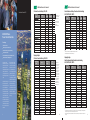
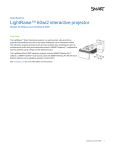
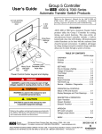
START-UP COMMISSIONING, SERVICE & SCHEDULED MAINTENANCE
A SCO Power Technologies
50 Hanover Road
F l o r ha m Pa r k , N J 0 7 9 3 2
USA
ASCO Services Inc. , provides a
wide range of technical services to
users of automatic transfer switches
in emergency and standby power
systems. These services include
comprehensive scheduled maintenance programs, modifications,
upgrades and emergency repairs.
Systems serviced range in complexity from a single automatic transfer
switch to multiple transfer switches
and engine generators.
ASCO Services is a wholly owned
subsidiary and the exclusive OEM
service arm of ASCO Power
Technologies, the world’s largest
manufacturer of power transfer
switching and control equipment.
Serving the needs of ASCO’s customers is a major focus; however,
ASCO Services is also routinely
called upon to perform regular
maintenance and emergency repairs
on equipment manufactured by
others.
ASCO Services offers comprehensive maintenance agreements that
detail the preventive care needed to
keep emergency power systems
ready to respond. A service agreement is an effective way to budget
in advance and avoid unexpected
expenditures. A 35 point checklist is
utilized to assure critical systems
and components are kept in top
operating condition. These preventive programs can be customized
for national accounts. This customization permits central corporate control of costs and scheduling.
Periodic reports provide detailed
information as to activity, maintenance performed and corrective
action.
8 0 0 8 0 0 A SCO
www.ascopower.com
www.ascoapu.com
ASCO Services deploys more than
75 service personnel strategically
located throughout the nation to
provide 24-hour response in emergency situations. Each region is
manned by experienced personnel
who receive ongoing support and
training in the newest equipment
concepts, design and controls.
Because equipment can be utilized
for a long number of years, field representatives also receive education
on older designs. This knowledge
can be invaluable in addressing total
system concerns, evaluating problems and providing solutions on site.
Service vans are equipped with parts
and advanced testing equipment
that facilitate these on-the-spot
repairs. ASCO Services
1-800-800-ASCO.
Emerson Network Power.
The global leader in enabling Business-Critical ContinuityTM.
EmersonNetworkPower.com
Outside Plant
AC Power
Connectivity
Embedded Computing
Embedded Power
DC Power
Infrastructure Management & Monitoring
Power Switching & Controls
Precision Cooling
Racks & Integrated Cabinets
Services
Surge Protection
Emerson Network Power and the Emerson Network Power logo are trademarks and service marks of Emerson Electric Co. ©2010 Emerson Electric Co.
Publication 3144 R3
19
© July, 2010
Printed in the U.S.A.
4000 SERIES DESIGNED TO FIT ANYWHERE*
4000 SERIES DESIGNED TO FIT ANYWHERE*
Critical Loads Demand ASCO
2-Position Transfer Switching 4ATS, 4NTS
Switch Rating
Amps
Poles
Width
Height
Depth
inches (mm) inches (mm) inches (mm)
Enclosed UL Type 1 2
ASCO 4000 SERIES
Power Transfer Switches
Protecting:
Healthcare Facilities
Web Hosting, Internet Data Centers
Commercial Buildings / Industrial Buildings
30, 70, 100, 125, 150, 200, 230
260, 400
600
800, 1000
1200
1600, 2000 1
1600, 2000 (front connected)3
2600, 3000 1
4000 1
2, 3 or 3 with neutral A/B
2, 3 or 3 with neutral A/B
2, 3 or 3 with neutral A/B
2, 3 or 3 with neutral A/B
2, 3 or 3 with neutral A/B
2, 3 or 3 with neutral A/B
2, 3 or 3 with neutral C
2, 3 or 3 with neutral A/B
18 (457)
24 (610)
24 (610)
34 (864)
38 (965)
38 (965)
38 (965)
38 (965)
48 (1219)
56 (1422)
63 (1600)
72 (1829)
87 (2210)
91 (2311)
87 (2210)
91 (2311)
13 (330)
14 (356)
17 (432)
20 (508)
23 (584)
48 (1219
23 (584)
60 (1524)
2, 3 or 3 with neutral A/B
60 (1524)
91 (2311)
72 (1829)
10-1/4 (260)
25 (635)
30 (762)
31 (787)
28 (711)
28 (711)
70 (1778)
5-1/2 (140)
8 (203)
9-7/8 (251)
12-7/8 (327)
26-1/4 (667)
30-3/4 (781)
53 (1272)
Notes:
1. Enclosures for 1600 - 4000
amp are free-standing with
removable top, sides, and
back.
2. Consult ASCO for dimensions on enclosures other
than UL type 1.
3. Optional arrangement.
Open Configuration
30, 70, 100, 125,150, 200, 230
260, 400
600
800, 1000, 1200
1600, 2000
2600, 3000
4000
Distributed Power / Load Management
As we become more
dependent on the quality
and reliability of electrical
power, interruption or
complete loss of power can
create serious and even
crippling financial losses, or
impose dangers to life and
safety.
ASCO Power Technologies
(ASCO) provides the solutions to handle the transfer
of critical loads to emergency sources reliably and
with state of the art products. Using ASCO products
can mean the difference
between a minor inconvenience and a major catastrophe. You’ll find ASCO Power
Transfer Switches wherever
there is a critical load to be
protected.
2
When flexibility in power
switching is a must, ASCO
offers a variety of product
solutions to meet virtually
every application requirement, including distributed
generation applications.
That’s why the 4000 SERIES
is available in open, delayed,
closed and closed soft load
configurations. Additionally,
switched or overlapping
neutral options provide for
reliable operation of ground
fault protection systems and
reduction of voltage transients from unbalanced load
switching.
Poles
Width
inches (mm)
2, 3 or 3 with neutral A/B
2, 3 or 3 with neutral A/B
2, 3 or 3 with neutral A/B
2, 3 or 3 with neutral A/B
2, 3 or 3 with neutral A/B
2, 3 or 3 with neutral C
2, 3 or 3 with neutral A/B
2, 3 or 3 with neutral A/C
24 (610)
24(610)
34 (864)
38 (965)
38 (965)
38 (965)
38 (965)
60 (1524)
56 (1422)
63 (1600)
72 (1829)
87 (2210)
91 (2311)
87 (2210)
91 (2311)
91 (2311)
150, 260, 400
2, 3 or 3 with neutral B
18-1/2 (470)
25 (635)
8 (203)
600
800, 1000, 1200
1600, 2000
2600, 3000
4000
2, 3 or 3 with neutral B
2, 3 or 3 with neutral B
2, 3 or 3 with neutral B
2, 3 or 3 with neutral B
2, 3 or 3 with neutral B
19 (483)
27 (686)
33-1/4 (845)
33-1/4 (845)
60 (1524)
30 (762)
31 (787)
28 (711)
28 (711)
70 (1778)
9-7/8 (251)
12-7/8 (327)
26-1/4 (667)
30-3/4 (781)
53 (1272)
Switch Rating
Amps
Height
Depth
inches (mm) inches (mm)
Enclosed UL Type 1 2
150, 260, 400
600
800, 1000
1200
1600, 2000 1
1600, 2000 (front connected)
3000 1
4000 1
14 (356)
17(432)
20 (508)
23 (584)
48 (1219)
23 (584)
60 (1524)
72 (1829)
Open Configuration
2, 3 or 3 with neutral B
2, 3 or 3 with neutral B
2, 3 or 3 with neutral B
2, 3 or 3 with neutral B
2, 3 or 3 with neutral B
2, 3 or 3 with neutral B
2, 3 or 3 with neutral B
10-1/4 (260)
18-1/2 (470)
19 (483)
27 (686)
33-1/4 (845)
33-1/4 (845)
60 (1524)
Notes:
1. Enclosures for 1600 - 4000 amp are free-standing with removable top, sides, and back.
2. Consult ASCO for dimensions on enclosures other than UL type 1.
Telecom Central Offices
Process Manufacturing / Wafer Fabrication Plants /
Closed Transition and Delayed Transition Transfer Switching
4ACTS, 4NCTS, 4ADTS, 4NDTS
Shipping Weights1
2-Position Transfer Switching 4ATS, 4NTS
Switch Rating
Amps
Poles
Enclosed
lb (kg)
Open
lb (kg)
30, 70, 100, 125
30, 70, 100, 125
30, 70, 100, 125
150, 200, 230
150, 200, 230
150, 200, 230
260, 400
260, 400
260, 400
600
600
600
800, 1000
800, 1000
800, 1000
1200
1200
1200
1600, 2000
1600, 2000
1600, 2000
2600, 3000
2600, 3000
2600, 3000
4000
4000
4000
2
3
3 with B
2
3
3 with B
2
3
3 with B
2
3
3 with B
2
3
3 with B
2
3
3 with B
2
3
3 with B
2
3
3 with B
2
3
3 with B
67 (31)
70 (32)
73 (33)
69 (32)
72 (33)
75 (34)
216 (98)
223 (101)
230 (105)
316 (143)
324 (147)
332 (151)
400 (182)
420 (192)
446 (203)
685 (312)
705 (321)
731 (333)
1110 (503)
1160 (525)
1210 (548)
1365 (620)
1430 (649)
1495 (679)
1969 (893)
2149 (975)
2328 (1056)
15 (7)
18 (8)
21 (10)
17 (8)
20 (9)
23 (11)
82 (37)
89 (40)
102 (46)
88 (40)
96 (44)
104 (47)
150 (68)
170 (78)
196 (90)
150 (68)
170 (78)
196 (90)
370 (167)
420 (190)
470 (213)
405 (184)
470 (213)
535 (243)
1258 (571)
1451 (658)
1623 (736)
Notes:
1. Open weights include
transfer switch and control
panel. 1200-4000 amp
enclosures require ventilation openings, refer to
drawings for details. Export
shipments may require a
wooden box, contact ASCO
for weights and dimensions.
Shipping Weights
Closed Transition and Delayed Transition Transfer Switching
4ACTS, 4NCTS, 4ADTS, 4NDTS
* All dimensions and weights
shown are approximate and
should not be used for
construction purposes.
Certified dimensions can be
furnished upon request.
Switch Rating
Amps
Poles
Enclosed
lb (kg)
Open*
lb (kg)
150, 260, 400
150, 260, 400
150, 260, 400
600
600
600
800, 1000
800, 1000
800, 1000
1200
1200
1200
1600, 2000
1600, 2000
1600, 2000
2600, 3000
2600, 3000
2600, 3000
4000
4000
4000
2
3
3 with B
2
3
3 with B
2
3
3 with B
2
3
3 with B
2
3
3 with B
2
3
3 with B
2
3
3 with B
235 (107)
242 (110)
250 (113)
335 (152)
343 (156)
352 (159)
420 (192)
450 (205)
480 (219)
710 (324)
740 (337)
770 (351)
1300 (590)
1350 (612)
1400 (635)
1555 (706)
1620 (735)
1685 (765)
1969 (893)
2149 (975)
2328 (1056)
101 (46)
108 (49)
115 (52)
107 (48)
115 (52)
124(56)
175 (80)
205 (94)
235 (108)
175 (80)
205 (94)
235 (108)
505 (229)
555 (252)
605 (274)
540 (245)
660 (300)
725 (329)
1258 (571)
1451 (658)
1623 (736)
Notes:
1. Open weights include transfer switch and control panel. 1200-4000 amp enclosures require ventilation openings, refer to drawings for details.
Export shipments may require a wooden box, contact ASCO for weights and dimensions.
20
* All dimensions and weights shown are approximate and should not be used for construction purposes. Certified dimensions can be furnished
upon request.
21
The Recognized Leader in Power Transfer
Switch Technology Offers the Most
Advanced Transfer Switches in the World.
4000 SERIES Power Transfer Switches
Product Features
• Conventional two-position transfer configuration,
plus closed and delayed transition modes of operation.
All configurations available with either automatic or
non-automatic control.
• UL listed to 1008 Transfer Switch Equipment &
CSA certified to CSA 22.2 No.178-1978 Automatic Transfer
Switches.
• Qualified to IEC 60947-6-1, CE marked (optional). (Limited
to certain accessories.)
• Rated up to 600 VAC, 30 through 4000 amperes.
• Reliable and field proven solenoid operating mechanism.
• High withstand and close-on ratings including short time
withstand current rating for optimum flexibility in circuit
breaker coordination (800-4000 amperes).
• Solid, switched neutral configurations available.
• Front replaceable main and arcing contacts (800-4000 amperes).
Fig. 1: Three Pole 4000 SERIES Automatic Transfer Switch
rated 800 amperes
4000 SERIES
ASCO Power Transfer Switches are the standard of the
industry. High speed transfer of loads between alternate sources of power, regardless of ampacity size, is
achieved by a reliable, field proven solenoid operating
mechanism. When combined with a programmable
microprocessor controller with keypad and LCD display,
they offer the most advanced method of transferring all
types of loads, such as motors, electronic drives, UPS’s
and microprocessor based systems. 4000 SERIES Power
Transfer Switches are available open or enclosed, in
ampacity sizes from 30 through 4000 amperes with a
limited selection of optional accessories.
• Programmable microprocessor controller with keypad and
LCD display.
• Industrial grade user interface with integrated controls and
indicating lights.
• Convenient one line diagram with switch position and source
acceptability LED indicators.
• Standard ground conductor connections.
• Four auxiliary contacts, two contacts closed when switch
is in normal position and two contacts closed when switch
is in emergency position.*
• Local/remote communications capability for interfacing
with ASCO POWERQUEST ® communication products.
*Only two contacts standard on 150-400A 4ACTS and 4NCTS
3
4000 SERIES POWER SWITCHING SOLUTIONS
Fig. 2: Four pole, Closed-Transition Transfer Switch
rated 1000 amperes in Type 1 enclosure.
Fig. 3: Four pole, Delayed-Transition
Transfer Switch rated 400 amperes
in Type 1 enclosure.
Closed-Transition Transfer Switching
Delayed-Transition Transfer Switching
ASCO Automatic Closed-Transition Transfer Switches feature
main contacts that overlap, permitting the transfer of electrical
loads without power interruption. The switch transfers in a
make-before-break mode if both sources are within acceptable
parameters. Control logic continuously monitors source
conditions and automatically determines whether the load
transfer should be open (conventional non-overlap mode) or
Closed-Transition. Available 150 through 4000 amperes.
ASCO Delayed-Transition Transfer Switches are designed to
provide transfer of loads between power sources with a
timed load disconnect position for an adjustable time
period. Applications include older style variable frequency
drives, rectifier banks, and load management applications.
Closed-Transition Transfer within 5 electrical degrees is
achieved passively, without control of engine generator set.
Therefore, no additional control wire runs are required between
the ATS and engine generator set governor. Plus, protective
relaying may not be required under normal operation since the
contact overlap time is less than 100 milliseconds
(consult your local utility on protective relay requirements).
Failure to synchronize indication, extended parallel time
protection, and transfer switch lock out are standard features.
4
• Available 150 through 4000 amperes.
• Utilizes reliable, field proven solenoid operating
mechanisms.
• Mechanical interlocks to prevent direct connection of both
sources.
• Indicator light (LED Type) for load disconnect position.
• Adjustable time delay for load disconnect position.
4000 SERIES POWER SWITCHING SOLUTIONS
Non-Automatic Transfer Switching
ASCO Non-Automatic Transfer Switches are electrically
operated units which are operated with manual control
switches mounted locally or at remote locations.
• Sizes from 30 through 4000 amperes.
• Microprocessor based controller provides for addition
of optional accessories.
• Controller prevents inadvertent operation under low
voltage conditions.
• Low control circuit operating currents allow for long
line runs between remotely mounted manual control
switches and the transfer switch.
• Source acceptability lights inform operator if sources
are available to accept load.
• Standard inphase monitor can be activated for
transferring motor loads.
Fig. 4: Three pole Non-Automatic,
electrically operated 200 ampere switch
shown in Type 1 enclosure.
Withstand and Close-On Ratings for all 4000 SERIES Products
5
4000 SERIES MICROPROCESSOR CONTROLLER
The 4000 SERIES microprocessor controller is used with all sizes of Power Transfer
Switches from 30 through 4000 amperes. It represents the most advanced digital
controller in the industry and includes, as standard, all of the voltage, frequency,
control, timing and diagnostic functions required for most emergency and standby
power applications.
Because of severe voltage transients frequently encountered with industrial
distribution systems, the microprocessor logic board is separated and isolated from
the power board as shown below. This improves electrical noise immunity performance and helps assure compliance with the rigorous transient suppression standards
highlighted below.
Fig. 5: 4000 SERIES
Microprocessor Controller.
Fig. 6: Microprocessor Power and Logic PC Boards.
4000 SERIES Microprocessor Controller
Emission Standard - Group 1, Class A
Generic Immunity Standard, from which:
Electrostatic Discharge (ESD) Immunity
Radiated Electromagnetic Field Immunity
Electrical Fast Transient (EFT) Immunity
Surge Transient Immunity
Conducted Radio-Frequency Field Immunity
Voltage Dips, Interruptions and Variations Immunity
6
EN 55011:1991
EN 50082-2:1995
EN 61000-4-2:1995
ENV 50140:1993
EN 61000-4-4:1995
EN 61000-4-5:1995
EN 61000-4-6:1996
EN 61000-4-11:1994
4000 SERIES MICROPROCESSOR CONTROLLER
Features
• Digital microprocessor.
• Touch pad programming of features and settings
without the need for meters, or variable power supplies.
• Password protection to prevent unauthorized tampering
of settings.
• Sixteen (16) selectable operating voltages available in a
single controller.
• Remote monitoring and control with ASCO
POWERQUEST ® communications.
products. Specify optional accessory 72A or 72E.
• On-board diagnostics provide control panel and ATS
status information to analyze system performance.
• Load shed option for bus optimization applications.
Specify optional accessory 30B.
• Displays and counts down active timing functions.
• Lamp Test - Provides a convenient way to verify
functionality of all LED’s on the user interface.
• Selectable multi-language display
(English, German, Portuguese, Spanish, or French. For
others contact ASCO).
Voltage and Frequency Sensing
Time Delays
• 3-Phase under and over voltage settings on normal
and emergency sources.
• Engine start time delay - delays engine starting signal to
override momentary normal source outages - adjustable 0
to 6 seconds.
• Under and over frequency settings on normal and
emergency.
• True RMS Voltage Sensing with +/- 1% accuracy;
Frequency Sensing Accuracy is +/- 0.2%.
• Transfer to emergency time delay - adjustable 0 to 60
minutes.
• Selectable settings: single or three phase voltage
sensing on normal and emergency; 50 or 60Hz.
• Emergency source stabilization time delay to ignore
momentary transients during initial generator set
loading - adjustable 0 to 6 seconds.
• Phase sequence sensing for phase sensitive loads.
• Retransfer to normal time delay with two settings:
• Voltage unbalance detection between phases.
• Power failure mode - 0 to 60 minutes.
• Test mode - 0 to 10 hours.
Status and Control Features
• Output contact (N/O or N/C) for engine-start signals.
• Unloaded running time delay for engine cooldown adjustable 0 to 60 minutes.
• Selection between “commit/no-commit” on transfer
to emergency after engine start and normal restores
before transfer.
• Fully programmable engine exerciser with seven
independent routines to exercise the engine generator,
with or without loads, on a daily, weekly, bi-weekly or
monthly basis.
• Terminals for remote test or customer contact for peak
shaving applications
• Contains all alarm signals, logic and time delays for
use with closed transition switches.
• Advanced inphase algorithm which automatically
measures the frequency difference between the two sources and
initiates transfer at appropriate phase angles to minimize
disturbances when transferring motor loads.
• Output signals for remote indication of normal and
emergency source acceptability.
• Statistical ATS/System monitoring data screens which provide:
• Total number of ATS transfers.
• Insynch time delay - 0 to 3 seconds.
• Failure to synchronize - 1 to 5 minutes.
• Extended parallel time - 0.1 to 1.0 seconds.
• Transfer switch locked out.
• Delayed transition load disconnect time delay adjustable 0 to 5 minutes. (Delayed Transition Switches
only.)
• Number of ATS transfers caused by power source failure.
• Total number of days ATS has been in operation.
• Total number of hours that the normal and emergency
sources have been available.
7
4000 SERIES POWER CONTROL CENTER SCREENS
Status
Source Status
System Status
Normal Source
Vab=480V....................ABC
Vbc=480V.........Vunbal=1%Vc
a=480V................60.0Hz
Normal OK
Load on Normal
Displays system status in clear, concise language.
Message shown indicates normal source is acceptable
and the load is connected to the normal source.
Displays voltage for each phase, frequency,
phase rotation and voltage unbalance for both
normal and emergency sources.
Time Delay Status
Inphase Transfer Mode
Normal OK
Emerg OK
TD.Engine.Cooldown:
4min15s
Waiting for In-Sync
-45o 0.02Hz
Active time delay status displays time
remaining until next control event.
Displays the relative phase angle between
sources and frequency differential to indicate
the controller is awaiting an inphase condition.
Settings
Voltage and Frequency Settings
Time Delay Settings
Normal Voltage
Dropout.............85%.408V
Pickup...............90%.432V
O.V. Trip.........110%.528V
TD N>E Xfer Signal
Bypass if N Fail: No
Pre Xfer: 0 min 20S
Post Xfer: 0 min 20S
Provides voltage and frequency setting values for
normal and emergency sources. Voltage pick-up,
dropout and trip settings are set in percentage of nominal
voltage and are also displayed in rms voltage values.
Engine Exerciser
Provides direct reading display for setting time delays.
Feature Settings
Shed Load
P1..................Engine.Exerciser
Enable:.....Yes....WLoad:....Yes
Start:19h30. ALL MON
Run.Time:...............2h15min
Direction:
Inphase: No
Seven independent programs, load/no load
selection, flexible run times and daily, weekly,
bi-weekly and monthly exercise routines.
From E
TD/0.25
Standard features can be activated with the keypad. As an
example, when enabled, the “shed load” option causes the
transfer switch to transfer the load off of the specified source.
If desired, the load shed transfer can be made inphase.
Data Logging
ATS Statistics
ATS Statistics
ATS Total Xfers: 46
SRC Fail Tot Xfers: 20
Days Energized: 36.5
8
Instant availability of statistical information on total
number of ATS transfers, number of transfers caused by
power failures and total days controller has been energized,
plus more.
4000 SERIES USER INTERFACE
User Interface Features
• Convenient One Line Diagram - Provides a clear view of
the position of the transfer switch, as well as the
acceptability of the Normal and Emergency sources.
• Source Acceptability LEDs - Provide true indication of the
acceptability of each source, as determined by the voltage, frequency, voltage unbalance, and phase sequence
settings of the control panel.
• Transfer Switch Position LEDs - Provide an indication of
which source the transfer switch is connected to.
• Transfer Test - Allows the user to test the operation of
the transfer switch under a simulated failure of the normal source. Holding for 15 seconds allows time for the
engine generator to come online and the transfer
switch to transfer the load.
• Retransfer to Normal - Allows the user to bypass the
programmed Retransfer to Normal time delay upon the
return of the normal source when the switch has transfered to emergency either during normal operation or a
transfer test.
Fig. 7: 4000 SERIES Open Transition User Interface
• Lamp Test - Provides a convenient way to verify the
functionality of all LEDs on the User Interface.
• User Controls Locked - Visually displays the status of
the keypad lock feature of the control panel. When
illuminated, the buttons of the User Interface are
disabled and the user must enter a password into the
control panel to unlock the switch. When LED is blinking, the controls are temporarily unlocked for five
minutes from the last button pressed.
Additional Closed Transition User
Interface Features
• Extended Parallel Time - Provides visual indication when
the pre-set extended parallel time has been exceeded.
The controls automatically open the emergency or normal main contacts. Separate contact also available to
shunt trip to an external breaker.
• Failure To Synchronize - Visually displays a failure to synchronize alarm if the time delay settings is exceeded,
during closed transition transfer operation.
• Transfer Switch Locked Out - Prevents transfer in either
direction if the extended parallel time is exceeded.
• Alarm Reset - Resets extended parallel and failure to
synchronize alarms.
Fig. 8: 4000 SERIES Closed Transition User Interface
• Closed Transition Bypass - Pushbutton allows transfer
between sources in an open transition mode.
9
4000 SERIES OPTIONAL ACCESSORIES
Time Delays
Customer Control Circuits
2C
30A
Load-shedding circuit initiated by opening of a
customer-supplied contact.
30B
Load-shedding circuit initiated by removal of
customer-supplied control voltage. (Specify voltage).
44G
Strip Heater with thermostat recommended for
outdoor applications on temperatures below 32O F
(0OC) to prevent condensation and freezing.
1G
Provides an extended time delay on engine starting.
The standard feature one time delay is adjustable from
zero to six seconds. Accessory 2C allows this time delay
to be adjustable from zero to sixty minutes in one
second intervals factory set at five minutes.
Similar to accessory 2C except using an external 24
volt DC power input. Available only as a feature of
accessory 18Z.
Add-on Boards
Indicators & Controls
18Z
Includes one Form C contact (Rated 2A @ 30VDC
14A/14B Additional auxiliary contact sets to indicate switch position. Two sets are typically standard. Maximum number of two additional sets. (Varies by configuration)
or .5A @ 125VAC) for each of the following:
6C
• Selective Load Disconnect. - Pre and post transfer
signal time delay for selective load disconnect with
a programmable bypass on source failures adjustable 0 to 5 minutes.
• Normal Source Acceptability.
• Emergency Source Acceptability.
Reset Switch for manual retransfer to normal with
automatic override upon emergency source failure.
Neutral Conductor Options
• Solid neutral, with fully-rated terminals. (AL-CU) UL Listed.
• Fourth contact can be set to mimic the acceptability contacts or annunciate any combination of
the acceptability contacts and/or any switch alarm
conditions available:
• Conventional neutral switching pole.
Note: Specify neutral option in catalog number, see page 18 for instructions.
Communications Options
72A
72E
Extended Parallel Time (Closed transition),
Serial communication module for remote
communications to ASCO POWERQUEST ® products. Also
allows 4000 SERIES Transfer Switches to communicate via
Modbus/RTU.
Ethernet connectivity module for remote communications to ASCO POWERQUEST ® products. Contains
embedded web pages for the remote monitoring of ASCO
products as well as some 3rd party devices. Also provides
Serial-to-Ethernet link with ability to communicate using
Modbus/TCP.
Failure to Synchronize (Closed transition),
Transfer Switch Locked Out (Closed transition),
Load Disconnected (Delayed transition).
• Accessory 18Z includes an extension of the engine
start time delay (feature) to 60 seconds if an external 24VDC supply is connected to a 4000 series
controller. This external power source will also allow
the LCD display to be active when both normal and
emergency sources are unavailable.
18Z2
Includes two 18Z accessory boards. (Maximum of
two 18Z accessory boards allowed.)
Fig. 9: 4000 SERIES Accessory 18Z
mounting on User Interface
1st Relay Board
Accessory 18Z
2nd Relay Board
Accesory 18Z2
Studs
Standoffs
10
4000 SERIES OPTIONAL ACCESSORIES
ASCO 5200 SERIES
Power Manager
POWER SYSTEM TOTAL
404 KW
+1.00 PF
0 KVAR
60.00 Hz
404 KVA
ATSºn NORM
The ASCO 5200 SERIES Power Manager is a microprocessor
based metering device that provides real-time measurements of single and three phase power systems. The
Power Manager uses digital signal processing technology
to measure voltage and current per phase; real, reactive
and apparent power, and bi-directional energy. All measurements can be viewed locally with a backlit liquid crystal
display and/or displayed remotely with ASCO
POWERQUEST ® products.
Direct voltage input for systems up to 600 Volts AC
can be monitored without the use of external potential
transformers (PTs). Measures three phase currents and a
fourth current input is available for measuring current
in the neutral conductor. The Power Manager includes
one discrete input for transfer switch position, eight
general purpose discrete inputs, and four relay outputs
for monitoring and controlling external devices.
Power Metering
• Voltage:
Line - Line: VAB, VBC, VCA, VAVERAGE
Line - Neutral: VAN, VBN, VCN, VAVERAGE
Fig. 10: ASCO 5200 SERIES Power Manager.
Configurable Designations
• Local - A four line, 20 character LCD backlit display.
• Remote - With optional Acc. 72A or 72E and Power Manager
monitoring systems.
• Provides user programmable setpoints based on twelve metering and I/O parameters. Each setpoint allows the user to select
the parameter, the trip & reset levels, the trip & reset time
delays and the alarm type or relay output to trigger. This can be
used for protective relaying and peak shaving applications.
• Frequency: 45.0 to 66.0 Hertz
Integrated ATS Features
• Current: IA, IB, IC, IAVERAGE
When configured on load of ATS:
• Unbalance %: Voltage, Amps
• Displays ATS position.
• Real Power: KWA, KWB, KWC, KWNET
• Displays power data as a function of ATS position
(normal/emergency).
• Reactive Power: KVARA, KVARB, KVARC, KVARNET
• Apparent Power: KVAA, KVAB, KVAC, KVANET
• Real Energy: KWHIMPORT, KWHEXPORT, KWHNET
• Reactive Energy: KVARHIMPORT, KVARHEXPORT,
KVARHNET
• Power Factor: PFA, PFB, PFC, PFNET
Data Access
• Eight digital inputs, four relay outputs.
• Input/Output 15-character, user definable screen
display for identification of input/output signals.
• Accumulates energy data separately for normal and
emergency sources.
Optional Configurations and
Connection Arrangements
Connected To:
Load
Normal
Emergency
With Display
Acc. 85L
Acc. 85N
Acc. 85M
Without Display
Acc. 75L
Acc. 75N
Acc. 75M
Add suffix “A” to above designations if neutral conductor monitoring is required.
Note: Accessory 75 and 85 includes component mounting, CTs, shorting
blocks and all necessary interwiring.
Note: The ASCO Power Manager is also available as a separate unit for monitoring electrical parameters anywhere in the power distribution system.
11
4000 SERIES POWER MONITORING & CONTROL
ASCO POWERQUEST Solutions
ASCO POWERQUEST ® communications products allow for the monitoring and control of power transfer
switches in your Emergency or Standby Power Distribution System. Local Area networks and Remote networks
are supported with either single or multiple points of access, and web-enabled communications allow access
to your power system from anywhere around the world.
Features
• Monitors and controls Power Transfer Switches and Engine Generators
• Monitors normal and emergency voltages and frequency
• Indicates transfer switch position and source availability
• Provides transfer and re-transfer of loads for system testing
• View normal and emergency voltage and frequency settings
• View transfer switch time-delay settings
• Provides transfer switch rating and identification
• Automatic paging notifies personnel, by e-mail or text message, of selected system alarms
• View current, power and power factor with ASCO Power Managers Connected to the System
• View transfer switch event log
• Provides transfer switch test schedule
Typical Network Architecture
ASCO 5110 (72A) Serial Modules
RS-485
ASCO 5150 (72E)
Connectivity Module
ASCO 5200
Power Manager
To Additional
Automatic
Transfer
Switches
Generator 1
ASCO
ATS 1
Ethernet
Switch
ASCO
POWERQUEST ®
32.15 Software
ASCO
ATS 2
ASCO 5110 (72A) Serial Modules
RS-485
ASCO 5150
(72E)
Connectivity
Module
ASCO 5200
Power Manager
To Additional
Automatic
Transfer
Switches
Generator 2
ASCO
ATS 3
12
ASCO
ATS 4
4000 SERIES POWER MONITORING & CONTROL
5110 Serial Module
The 5110 Serial Module is used to allow local or remote communications with ASCO
POWERQUEST ® communication products.
The module is used to connect the 4000 SERIES transfer switches to a serial network
via an RS-485 interface. The module has two port connectors used for ATS & Power
Manager connectivity.
The serial connection is accomplished from a 5-pin terminal header/socket block.
RS- 485 serial networks allow for up to 32 modules to be set up in a daisy chain
configuration to connect to POWERQUEST ® systems.
Fig. 11: Serial
Module 72A
5150 Connectivity Module
The 5150 Connectivity Module is used to bring several different serial devices that
communicate at different baud rates and with different protocols to a common
Ethernet media.
The module is used to connect 4000 SERIES transfer switches, and ASCO Remote
Annuciators to a standard Ethernet TCP/IP network with standard 10base T(RJ-45)
connectors. The module has customized embedded JAVATM applets (program
applications for an internet browser) for each monitored device that loads
automatically to a standard Web Browser.
The module is designed to communicate with up to 8 clients such as Web
applications (web pages), POWERQUEST ® , or third party Modbus® devices
simultaneously over an Ethernet connection.
Fig. 12: Connectivity
Module 72E
5350 Remote Annunciator
The ASCO Power Transfer Switch Remote Annunciator is a stand-alone, industrial
grade interface device providing you with the most critical transfer switch status
indication and transfer/retransfer control for up to eight switches. Ethernet
technology is built in for faster and more reliable communications. LEDs
indicate switch status and position, while separate push buttons individually initiate
transfer switch operation and testing. Transfer switch annunciators can be set up in
multiple locations to monitor various transfer switches, allowing redundant and
distributed annunciation.
Fig. 13: ASCO
Remote Annuciator
13
32.15
ASCO 32.15 POWER INTERFACE SOFTWARE
The ASCO 32.15 Power Interface is a computer-based monitoring and control software package. When
combined with ASCO 72E/72A Communications Interface modules and the ASCO 5200 SERIES Power Manager,
it provides a centralized and comprehensive monitoring and control interface of power transfer switches and
engine generators. A one-line diagram, power metering information, transfer switch controls and event-log
data, and engine-generator screens are available to users with password protected controls.
Summary Screen
Current and Historical
Alarms
The Current Alarm screen displays all currently
active alarms. It provides the date of the alarm,
along with IP and Name of the device with the
issue. In addition, a detailed description of the
alarm is provided to help the operator in pinpointing the issue. All historical alarms can be
viewed as well by selecting the “Historical” tab.
L
E
E
14
N
N
Convenient One-Line Diagram
• Colored icons highlighted to show source availability
and which source is connected to load.
32.15
Transfer Switch Detail Screen
• ATS rating and identification data is displayed.
• Allows remote testing and time delay bypass.
• Voltage, frequency, phase sequence, voltage unbalance
and time delay settings can be checked.
• Viewing of engine exercise schedules.
• Displays phase to phase voltage on normal and
emergency.
• Provides complete system status message from
4000 series microprocessor controller.
• View event log on the last 99 events for each ATS.
• Arrange test schedules for transfer switches.
• Provides for monitoring of local site or remote sites.
Power Manager Detail Screen
• Voltage: phase to phase; phase to neutral and
voltage unbalance.
• 3 phase currents and neutral (optional).
• Frequency.
• Kilowatt hours - normal and emergency.
• Status and control of four relay outputs.
• Status of eight digital inputs.
• Device ratings: CT and PT ratio.
Engine-Generator Details
• Voltage: Phase to phase; Phase to neutral
• Current for each phase.
• Kilowatts and kilowatt hours total.
• Frequency and power factor.
• Status and control of four digital outputs which can be
customized by the user.
• Status of eight digital inputs.
• “Alarm Enabled” selection. These alarms flash the
“engine-generator” icon on the summary screen.
• Digital inputs for engine malfunctions are derived
from engine mounted sensors (supplied by others).
15
Solutions
5500 SERIES Thin Web Server
The ASCO Thin Web Server is an internet-based thin client application, which provides monitoring and control of
transfer switches and engine generators from anywhere in the world. With ASCO 72E/72A Communications Interface
modules and ASCO 5200 SERIES Power Managers, it brings the power interface to your browser with your user name
and password. Alarms and event logs are provided through the browser, while simultaneously transmitting an email
indicating that an alarm has occurred with one or more transfer switches.
Fig. 24: Thin Web Server
Fig. 25: Thin Web's html interface screen shot
Communications Products for 4000 SERIES Transfer Switches
Description
Acc. Option
Catalog No.
Serial Module
72A
5110
Connectivity Module
72E
5150
Power Manager with Display*
85L
5220D
Thin Web Server*
—
5510E
Software Package*
—
32.15
* These products are available as separate items only. They can be ordered by catalog numbers shown in above chart.
Solutions Comparison
ASCO Connectivity Solution Guide
Feature
Quantity of Monitored / Controlled Power Transfer
Switches per LAN
32.15
32
5500
5350
5150
Thin Web Server Connectivity Module Remote Annunciator
64
1024+
8
4
8
1024+
0
Control & Monitoring Capability
Yes
Yes
No
Yes
Embedded Web Pages
No
Yes
Yes
Yes
Ethernet Network Compatible
Yes
Yes
Yes
Yes
Monitor Multiple Protocols & Baud Rates
(ASCO I, ASCO II, Modbus)
No
No
Yes
Yes
Intranet
Internet
Intranet
Intranet
Number of Monitored / Controlled Gensets
Monitor Multiple Sites
Multiple Client Access
No
Up to 8
Up to 8
Up to 8
Client Software Required
Yes
Internet Explorer
Internet Explorer
Internet Explorer*
Monitors Dissimilar ASCO Controllers on Common LAN
No
No
Yes
Yes
Communicates with ASCO Remote Annuciators
No
No
Yes
Yes
Email / Paging Alarms
No
Yes
No
No
No
Yes**
Historical Trending Option Alarms
* Internet Explorer only required for initial communications setup.
** Historical trending not available on Remote Annuciator.
16
POWERQUEST ®
No
Yes
Solutions
Remote
Access
Computer
Local
Computer
Ethernet
RS 485
Ethernet Switch
Internet
Firewall
Pager
ASCO 5500
Thin Web
Server
Email Server
Ethernet
Monitoring
and Control
ATS Annunciator
Modbus/RTU
RS 485
Building
Management
Computer
ASCO
Digital Paralleling
System
Ethernet Switch
ASCO
5110 (72A)
Serial
Modules
ASCO
5150 (72E)
Connectivity
Modules
To Additional
Automatic
Transfer
Switches
ASCO
ATS 1
ASCO
ATS 2
To Additional
Automatic
Transfer
Switches
ASCO
ATS 1
ASCO
ATS 2
17
4000 SERIES ORDERING INFORMATION
To order an ASCO 4000 SERIES Power Transfer Switch, complete the following catalog number:
4
A
TS
A
+
Neutral
Code*
Product
A
N
Automatic
NonAutomatic
+
Phase
Poles
---
No Neutral
CTS
Closed
Transition
A
Solid Neutral
DTS
Delayed
Transition
B
TS
Conventional
2-Position
3
2
3
Switched
Neutral
400
+
N
+ 5X +
C
Voltage
Code
Grp
Code
Enclosure
+
Amperes
30
1000
70
1200
100
1600
125
2000
A
B
C
D
E
F
150
2600
H
200 1
3000
230 1
4000
J
K
L
M
N
P
Q
R
260
400
600
115
120
208
220
230
240
380
400
415
440
460
480
550
575
600
800
*Note:
5
5Xoptional
accessories
---
No enclosure
C
Type 1 enclosure
F
Type 3R
enclosure
G
Type 4 enclosure
H
Type 4X enclosure
L
Type 12
enclosure
M
Type 3R secure
double door
N
Type 4 secure
double door
P
Type 4X secure
double door
Q
Type 12 secure
double door
R
Type 3RX secure
double door
(Stainless Steel)
1. 200 and 230 amp switch limited to 480 volts maximum.
2. Type 304 Stainless steel is standard. To provide an improved reduction in corrosion in salt or marine environments,
specify optional type 316 stainless steel.
The Example Catalog Number above is 4ATSA3400N5XC
(X is used to specify optional accessories).
Transfer Switch Configurations
4ATS, 4NTS, 4ADTS, 4NDTS, 4ACTS, 4NCTS
Sizes of UL-Listed Solderless Screw-Type
Terminals for External Power Connections
Switch Rating
amps
Max # of Conductors
per Terminal
Range of AL- CU
Conductor Sizes
30 -230 1 ATS,NTS
One
#14 to 4/0 AWG
150 DTS, CTS
One
#4 AWG to 600 MCM
Two
#1/0 AWG to 250 MCM
260-400
#4 AWG to 600 MCM
Two
#1/0 AWG to 250 MCM
600
Two
#2 AWG to 600 MCM
800-1200
Four
#1/0 AWG to 600 MCM
1600-20002
Six
#1/0 AWG to 600 MCM
2600, 3000
Twelve
#1/0 AWG to 600 MCM
Twelve
#2/0 AWG to 600 MCM
4000 2
18
One
2
Notes:
1. 200 and 230 amp rating for copper
conductors only.
2. All main terminals are rear connected. 1600
& 2000 amp switches are available in optional front connected arrangement. Specify
optional accessory 40MY for 1600 amp and
40NY for 2000 amp. WCR rating limited to
85,000 amp rms symmetrical. see pages 20,
21 for enclosure dimensions.
2
2
START-UP COMMISSIONING, SERVICE & SCHEDULED MAINTENANCE
A SCO Power Technologies
50 Hanover Road
F l o r ha m Pa r k , N J 0 7 9 3 2
USA
ASCO Services Inc. , provides a
wide range of technical services to
users of automatic transfer switches
in emergency and standby power
systems. These services include
comprehensive scheduled maintenance programs, modifications,
upgrades and emergency repairs.
Systems serviced range in complexity from a single automatic transfer
switch to multiple transfer switches
and engine generators.
ASCO Services is a wholly owned
subsidiary and the exclusive OEM
service arm of ASCO Power
Technologies, the world’s largest
manufacturer of power transfer
switching and control equipment.
Serving the needs of ASCO’s customers is a major focus; however,
ASCO Services is also routinely
called upon to perform regular
maintenance and emergency repairs
on equipment manufactured by
others.
ASCO Services offers comprehensive maintenance agreements that
detail the preventive care needed to
keep emergency power systems
ready to respond. A service agreement is an effective way to budget
in advance and avoid unexpected
expenditures. A 35 point checklist is
utilized to assure critical systems
and components are kept in top
operating condition. These preventive programs can be customized
for national accounts. This customization permits central corporate control of costs and scheduling.
Periodic reports provide detailed
information as to activity, maintenance performed and corrective
action.
8 0 0 8 0 0 A SCO
www.ascopower.com
www.ascoapu.com
ASCO Services deploys more than
75 service personnel strategically
located throughout the nation to
provide 24-hour response in emergency situations. Each region is
manned by experienced personnel
who receive ongoing support and
training in the newest equipment
concepts, design and controls.
Because equipment can be utilized
for a long number of years, field representatives also receive education
on older designs. This knowledge
can be invaluable in addressing total
system concerns, evaluating problems and providing solutions on site.
Service vans are equipped with parts
and advanced testing equipment
that facilitate these on-the-spot
repairs. ASCO Services
1-800-800-ASCO.
Emerson Network Power.
The global leader in enabling Business-Critical ContinuityTM.
EmersonNetworkPower.com
Outside Plant
AC Power
Connectivity
Embedded Computing
Embedded Power
DC Power
Infrastructure Management & Monitoring
Power Switching & Controls
Precision Cooling
Racks & Integrated Cabinets
Services
Surge Protection
Emerson Network Power and the Emerson Network Power logo are trademarks and service marks of Emerson Electric Co. ©2010 Emerson Electric Co.
Publication 3144 R3
19
© July, 2010
Printed in the U.S.A.
4000 SERIES DESIGNED TO FIT ANYWHERE*
4000 SERIES DESIGNED TO FIT ANYWHERE*
Critical Loads Demand ASCO
2-Position Transfer Switching 4ATS, 4NTS
Switch Rating
Amps
Poles
Width
Height
Depth
inches (mm) inches (mm) inches (mm)
Enclosed UL Type 1 2
ASCO 4000 SERIES
Power Transfer Switches
Protecting:
Healthcare Facilities
Web Hosting, Internet Data Centers
Commercial Buildings / Industrial Buildings
30, 70, 100, 125, 150, 200, 230
260, 400
600
800, 1000
1200
1600, 2000 1
1600, 2000 (front connected)3
2600, 3000 1
4000 1
2, 3 or 3 with neutral A/B
2, 3 or 3 with neutral A/B
2, 3 or 3 with neutral A/B
2, 3 or 3 with neutral A/B
2, 3 or 3 with neutral A/B
2, 3 or 3 with neutral A/B
2, 3 or 3 with neutral C
2, 3 or 3 with neutral A/B
18 (457)
24 (610)
24 (610)
34 (864)
38 (965)
38 (965)
38 (965)
38 (965)
48 (1219)
56 (1422)
63 (1600)
72 (1829)
87 (2210)
91 (2311)
87 (2210)
91 (2311)
13 (330)
14 (356)
17 (432)
20 (508)
23 (584)
48 (1219
23 (584)
60 (1524)
2, 3 or 3 with neutral A/B
60 (1524)
91 (2311)
72 (1829)
10-1/4 (260)
25 (635)
30 (762)
31 (787)
28 (711)
28 (711)
70 (1778)
5-1/2 (140)
8 (203)
9-7/8 (251)
12-7/8 (327)
26-1/4 (667)
30-3/4 (781)
53 (1272)
Notes:
1. Enclosures for 1600 - 4000
amp are free-standing with
removable top, sides, and
back.
2. Consult ASCO for dimensions on enclosures other
than UL type 1.
3. Optional arrangement.
Open Configuration
30, 70, 100, 125,150, 200, 230
260, 400
600
800, 1000, 1200
1600, 2000
2600, 3000
4000
Distributed Power / Load Management
As we become more
dependent on the quality
and reliability of electrical
power, interruption or
complete loss of power can
create serious and even
crippling financial losses, or
impose dangers to life and
safety.
ASCO Power Technologies
(ASCO) provides the solutions to handle the transfer
of critical loads to emergency sources reliably and
with state of the art products. Using ASCO products
can mean the difference
between a minor inconvenience and a major catastrophe. You’ll find ASCO Power
Transfer Switches wherever
there is a critical load to be
protected.
2
When flexibility in power
switching is a must, ASCO
offers a variety of product
solutions to meet virtually
every application requirement, including distributed
generation applications.
That’s why the 4000 SERIES
is available in open, delayed,
closed and closed soft load
configurations. Additionally,
switched or overlapping
neutral options provide for
reliable operation of ground
fault protection systems and
reduction of voltage transients from unbalanced load
switching.
Poles
Width
inches (mm)
2, 3 or 3 with neutral A/B
2, 3 or 3 with neutral A/B
2, 3 or 3 with neutral A/B
2, 3 or 3 with neutral A/B
2, 3 or 3 with neutral A/B
2, 3 or 3 with neutral C
2, 3 or 3 with neutral A/B
2, 3 or 3 with neutral A/C
24 (610)
24(610)
34 (864)
38 (965)
38 (965)
38 (965)
38 (965)
60 (1524)
56 (1422)
63 (1600)
72 (1829)
87 (2210)
91 (2311)
87 (2210)
91 (2311)
91 (2311)
150, 260, 400
2, 3 or 3 with neutral B
18-1/2 (470)
25 (635)
8 (203)
600
800, 1000, 1200
1600, 2000
2600, 3000
4000
2, 3 or 3 with neutral B
2, 3 or 3 with neutral B
2, 3 or 3 with neutral B
2, 3 or 3 with neutral B
2, 3 or 3 with neutral B
19 (483)
27 (686)
33-1/4 (845)
33-1/4 (845)
60 (1524)
30 (762)
31 (787)
28 (711)
28 (711)
70 (1778)
9-7/8 (251)
12-7/8 (327)
26-1/4 (667)
30-3/4 (781)
53 (1272)
Switch Rating
Amps
Height
Depth
inches (mm) inches (mm)
Enclosed UL Type 1 2
150, 260, 400
600
800, 1000
1200
1600, 2000 1
1600, 2000 (front connected)
3000 1
4000 1
14 (356)
17(432)
20 (508)
23 (584)
48 (1219)
23 (584)
60 (1524)
72 (1829)
Open Configuration
2, 3 or 3 with neutral B
2, 3 or 3 with neutral B
2, 3 or 3 with neutral B
2, 3 or 3 with neutral B
2, 3 or 3 with neutral B
2, 3 or 3 with neutral B
2, 3 or 3 with neutral B
10-1/4 (260)
18-1/2 (470)
19 (483)
27 (686)
33-1/4 (845)
33-1/4 (845)
60 (1524)
Notes:
1. Enclosures for 1600 - 4000 amp are free-standing with removable top, sides, and back.
2. Consult ASCO for dimensions on enclosures other than UL type 1.
Telecom Central Offices
Process Manufacturing / Wafer Fabrication Plants /
Closed Transition and Delayed Transition Transfer Switching
4ACTS, 4NCTS, 4ADTS, 4NDTS
Shipping Weights1
2-Position Transfer Switching 4ATS, 4NTS
Switch Rating
Amps
Poles
Enclosed
lb (kg)
Open
lb (kg)
30, 70, 100, 125
30, 70, 100, 125
30, 70, 100, 125
150, 200, 230
150, 200, 230
150, 200, 230
260, 400
260, 400
260, 400
600
600
600
800, 1000
800, 1000
800, 1000
1200
1200
1200
1600, 2000
1600, 2000
1600, 2000
2600, 3000
2600, 3000
2600, 3000
4000
4000
4000
2
3
3 with B
2
3
3 with B
2
3
3 with B
2
3
3 with B
2
3
3 with B
2
3
3 with B
2
3
3 with B
2
3
3 with B
2
3
3 with B
67 (31)
70 (32)
73 (33)
69 (32)
72 (33)
75 (34)
216 (98)
223 (101)
230 (105)
316 (143)
324 (147)
332 (151)
400 (182)
420 (192)
446 (203)
685 (312)
705 (321)
731 (333)
1110 (503)
1160 (525)
1210 (548)
1365 (620)
1430 (649)
1495 (679)
1969 (893)
2149 (975)
2328 (1056)
15 (7)
18 (8)
21 (10)
17 (8)
20 (9)
23 (11)
82 (37)
89 (40)
102 (46)
88 (40)
96 (44)
104 (47)
150 (68)
170 (78)
196 (90)
150 (68)
170 (78)
196 (90)
370 (167)
420 (190)
470 (213)
405 (184)
470 (213)
535 (243)
1258 (571)
1451 (658)
1623 (736)
Notes:
1. Open weights include
transfer switch and control
panel. 1200-4000 amp
enclosures require ventilation openings, refer to
drawings for details. Export
shipments may require a
wooden box, contact ASCO
for weights and dimensions.
Shipping Weights
Closed Transition and Delayed Transition Transfer Switching
4ACTS, 4NCTS, 4ADTS, 4NDTS
* All dimensions and weights
shown are approximate and
should not be used for
construction purposes.
Certified dimensions can be
furnished upon request.
Switch Rating
Amps
Poles
Enclosed
lb (kg)
Open*
lb (kg)
150, 260, 400
150, 260, 400
150, 260, 400
600
600
600
800, 1000
800, 1000
800, 1000
1200
1200
1200
1600, 2000
1600, 2000
1600, 2000
2600, 3000
2600, 3000
2600, 3000
4000
4000
4000
2
3
3 with B
2
3
3 with B
2
3
3 with B
2
3
3 with B
2
3
3 with B
2
3
3 with B
2
3
3 with B
235 (107)
242 (110)
250 (113)
335 (152)
343 (156)
352 (159)
420 (192)
450 (205)
480 (219)
710 (324)
740 (337)
770 (351)
1300 (590)
1350 (612)
1400 (635)
1555 (706)
1620 (735)
1685 (765)
1969 (893)
2149 (975)
2328 (1056)
101 (46)
108 (49)
115 (52)
107 (48)
115 (52)
124(56)
175 (80)
205 (94)
235 (108)
175 (80)
205 (94)
235 (108)
505 (229)
555 (252)
605 (274)
540 (245)
660 (300)
725 (329)
1258 (571)
1451 (658)
1623 (736)
Notes:
1. Open weights include transfer switch and control panel. 1200-4000 amp enclosures require ventilation openings, refer to drawings for details.
Export shipments may require a wooden box, contact ASCO for weights and dimensions.
20
* All dimensions and weights shown are approximate and should not be used for construction purposes. Certified dimensions can be furnished
upon request.
21
4000 SERIES DESIGNED TO FIT ANYWHERE*
4000 SERIES DESIGNED TO FIT ANYWHERE*
Critical Loads Demand ASCO
2-Position Transfer Switching 4ATS, 4NTS
Switch Rating
Amps
Poles
Width
Height
Depth
inches (mm) inches (mm) inches (mm)
Enclosed UL Type 1 2
ASCO 4000 SERIES
Power Transfer Switches
Protecting:
Healthcare Facilities
Web Hosting, Internet Data Centers
Commercial Buildings / Industrial Buildings
30, 70, 100, 125, 150, 200, 230
260, 400
600
800, 1000
1200
1600, 2000 1
1600, 2000 (front connected)3
2600, 3000 1
4000 1
2, 3 or 3 with neutral A/B
2, 3 or 3 with neutral A/B
2, 3 or 3 with neutral A/B
2, 3 or 3 with neutral A/B
2, 3 or 3 with neutral A/B
2, 3 or 3 with neutral A/B
2, 3 or 3 with neutral C
2, 3 or 3 with neutral A/B
18 (457)
24 (610)
24 (610)
34 (864)
38 (965)
38 (965)
38 (965)
38 (965)
48 (1219)
56 (1422)
63 (1600)
72 (1829)
87 (2210)
91 (2311)
87 (2210)
91 (2311)
13 (330)
14 (356)
17 (432)
20 (508)
23 (584)
48 (1219
23 (584)
60 (1524)
2, 3 or 3 with neutral A/B
60 (1524)
91 (2311)
72 (1829)
10-1/4 (260)
25 (635)
30 (762)
31 (787)
28 (711)
28 (711)
70 (1778)
5-1/2 (140)
8 (203)
9-7/8 (251)
12-7/8 (327)
26-1/4 (667)
30-3/4 (781)
53 (1272)
Notes:
1. Enclosures for 1600 - 4000
amp are free-standing with
removable top, sides, and
back.
2. Consult ASCO for dimensions on enclosures other
than UL type 1.
3. Optional arrangement.
Open Configuration
30, 70, 100, 125,150, 200, 230
260, 400
600
800, 1000, 1200
1600, 2000
2600, 3000
4000
Distributed Power / Load Management
As we become more
dependent on the quality
and reliability of electrical
power, interruption or
complete loss of power can
create serious and even
crippling financial losses, or
impose dangers to life and
safety.
ASCO Power Technologies
(ASCO) provides the solutions to handle the transfer
of critical loads to emergency sources reliably and
with state of the art products. Using ASCO products
can mean the difference
between a minor inconvenience and a major catastrophe. You’ll find ASCO Power
Transfer Switches wherever
there is a critical load to be
protected.
2
When flexibility in power
switching is a must, ASCO
offers a variety of product
solutions to meet virtually
every application requirement, including distributed
generation applications.
That’s why the 4000 SERIES
is available in open, delayed,
closed and closed soft load
configurations. Additionally,
switched or overlapping
neutral options provide for
reliable operation of ground
fault protection systems and
reduction of voltage transients from unbalanced load
switching.
Poles
Width
inches (mm)
2, 3 or 3 with neutral A/B
2, 3 or 3 with neutral A/B
2, 3 or 3 with neutral A/B
2, 3 or 3 with neutral A/B
2, 3 or 3 with neutral A/B
2, 3 or 3 with neutral C
2, 3 or 3 with neutral A/B
2, 3 or 3 with neutral A/C
24 (610)
24(610)
34 (864)
38 (965)
38 (965)
38 (965)
38 (965)
60 (1524)
56 (1422)
63 (1600)
72 (1829)
87 (2210)
91 (2311)
87 (2210)
91 (2311)
91 (2311)
150, 260, 400
2, 3 or 3 with neutral B
18-1/2 (470)
25 (635)
8 (203)
600
800, 1000, 1200
1600, 2000
2600, 3000
4000
2, 3 or 3 with neutral B
2, 3 or 3 with neutral B
2, 3 or 3 with neutral B
2, 3 or 3 with neutral B
2, 3 or 3 with neutral B
19 (483)
27 (686)
33-1/4 (845)
33-1/4 (845)
60 (1524)
30 (762)
31 (787)
28 (711)
28 (711)
70 (1778)
9-7/8 (251)
12-7/8 (327)
26-1/4 (667)
30-3/4 (781)
53 (1272)
Switch Rating
Amps
Height
Depth
inches (mm) inches (mm)
Enclosed UL Type 1 2
150, 260, 400
600
800, 1000
1200
1600, 2000 1
1600, 2000 (front connected)
3000 1
4000 1
14 (356)
17(432)
20 (508)
23 (584)
48 (1219)
23 (584)
60 (1524)
72 (1829)
Open Configuration
2, 3 or 3 with neutral B
2, 3 or 3 with neutral B
2, 3 or 3 with neutral B
2, 3 or 3 with neutral B
2, 3 or 3 with neutral B
2, 3 or 3 with neutral B
2, 3 or 3 with neutral B
10-1/4 (260)
18-1/2 (470)
19 (483)
27 (686)
33-1/4 (845)
33-1/4 (845)
60 (1524)
Notes:
1. Enclosures for 1600 - 4000 amp are free-standing with removable top, sides, and back.
2. Consult ASCO for dimensions on enclosures other than UL type 1.
Telecom Central Offices
Process Manufacturing / Wafer Fabrication Plants /
Closed Transition and Delayed Transition Transfer Switching
4ACTS, 4NCTS, 4ADTS, 4NDTS
Shipping Weights1
2-Position Transfer Switching 4ATS, 4NTS
Switch Rating
Amps
Poles
Enclosed
lb (kg)
Open
lb (kg)
30, 70, 100, 125
30, 70, 100, 125
30, 70, 100, 125
150, 200, 230
150, 200, 230
150, 200, 230
260, 400
260, 400
260, 400
600
600
600
800, 1000
800, 1000
800, 1000
1200
1200
1200
1600, 2000
1600, 2000
1600, 2000
2600, 3000
2600, 3000
2600, 3000
4000
4000
4000
2
3
3 with B
2
3
3 with B
2
3
3 with B
2
3
3 with B
2
3
3 with B
2
3
3 with B
2
3
3 with B
2
3
3 with B
2
3
3 with B
67 (31)
70 (32)
73 (33)
69 (32)
72 (33)
75 (34)
216 (98)
223 (101)
230 (105)
316 (143)
324 (147)
332 (151)
400 (182)
420 (192)
446 (203)
685 (312)
705 (321)
731 (333)
1110 (503)
1160 (525)
1210 (548)
1365 (620)
1430 (649)
1495 (679)
1969 (893)
2149 (975)
2328 (1056)
15 (7)
18 (8)
21 (10)
17 (8)
20 (9)
23 (11)
82 (37)
89 (40)
102 (46)
88 (40)
96 (44)
104 (47)
150 (68)
170 (78)
196 (90)
150 (68)
170 (78)
196 (90)
370 (167)
420 (190)
470 (213)
405 (184)
470 (213)
535 (243)
1258 (571)
1451 (658)
1623 (736)
Notes:
1. Open weights include
transfer switch and control
panel. 1200-4000 amp
enclosures require ventilation openings, refer to
drawings for details. Export
shipments may require a
wooden box, contact ASCO
for weights and dimensions.
Shipping Weights
Closed Transition and Delayed Transition Transfer Switching
4ACTS, 4NCTS, 4ADTS, 4NDTS
* All dimensions and weights
shown are approximate and
should not be used for
construction purposes.
Certified dimensions can be
furnished upon request.
Switch Rating
Amps
Poles
Enclosed
lb (kg)
Open*
lb (kg)
150, 260, 400
150, 260, 400
150, 260, 400
600
600
600
800, 1000
800, 1000
800, 1000
1200
1200
1200
1600, 2000
1600, 2000
1600, 2000
2600, 3000
2600, 3000
2600, 3000
4000
4000
4000
2
3
3 with B
2
3
3 with B
2
3
3 with B
2
3
3 with B
2
3
3 with B
2
3
3 with B
2
3
3 with B
235 (107)
242 (110)
250 (113)
335 (152)
343 (156)
352 (159)
420 (192)
450 (205)
480 (219)
710 (324)
740 (337)
770 (351)
1300 (590)
1350 (612)
1400 (635)
1555 (706)
1620 (735)
1685 (765)
1969 (893)
2149 (975)
2328 (1056)
101 (46)
108 (49)
115 (52)
107 (48)
115 (52)
124(56)
175 (80)
205 (94)
235 (108)
175 (80)
205 (94)
235 (108)
505 (229)
555 (252)
605 (274)
540 (245)
660 (300)
725 (329)
1258 (571)
1451 (658)
1623 (736)
Notes:
1. Open weights include transfer switch and control panel. 1200-4000 amp enclosures require ventilation openings, refer to drawings for details.
Export shipments may require a wooden box, contact ASCO for weights and dimensions.
20
* All dimensions and weights shown are approximate and should not be used for construction purposes. Certified dimensions can be furnished
upon request.
21
START-UP COMMISSIONING, SERVICE & SCHEDULED MAINTENANCE
A SCO Power Technologies
50 Hanover Road
F l o r ha m Pa r k , N J 0 7 9 3 2
USA
ASCO Services Inc. , provides a
wide range of technical services to
users of automatic transfer switches
in emergency and standby power
systems. These services include
comprehensive scheduled maintenance programs, modifications,
upgrades and emergency repairs.
Systems serviced range in complexity from a single automatic transfer
switch to multiple transfer switches
and engine generators.
ASCO Services is a wholly owned
subsidiary and the exclusive OEM
service arm of ASCO Power
Technologies, the world’s largest
manufacturer of power transfer
switching and control equipment.
Serving the needs of ASCO’s customers is a major focus; however,
ASCO Services is also routinely
called upon to perform regular
maintenance and emergency repairs
on equipment manufactured by
others.
ASCO Services offers comprehensive maintenance agreements that
detail the preventive care needed to
keep emergency power systems
ready to respond. A service agreement is an effective way to budget
in advance and avoid unexpected
expenditures. A 35 point checklist is
utilized to assure critical systems
and components are kept in top
operating condition. These preventive programs can be customized
for national accounts. This customization permits central corporate control of costs and scheduling.
Periodic reports provide detailed
information as to activity, maintenance performed and corrective
action.
8 0 0 8 0 0 A SCO
www.ascopower.com
www.ascoapu.com
ASCO Services deploys more than
75 service personnel strategically
located throughout the nation to
provide 24-hour response in emergency situations. Each region is
manned by experienced personnel
who receive ongoing support and
training in the newest equipment
concepts, design and controls.
Because equipment can be utilized
for a long number of years, field representatives also receive education
on older designs. This knowledge
can be invaluable in addressing total
system concerns, evaluating problems and providing solutions on site.
Service vans are equipped with parts
and advanced testing equipment
that facilitate these on-the-spot
repairs. ASCO Services
1-800-800-ASCO.
Emerson Network Power.
The global leader in enabling Business-Critical ContinuityTM.
EmersonNetworkPower.com
Outside Plant
AC Power
Connectivity
Embedded Computing
Embedded Power
DC Power
Infrastructure Management & Monitoring
Power Switching & Controls
Precision Cooling
Racks & Integrated Cabinets
Services
Surge Protection
Emerson Network Power and the Emerson Network Power logo are trademarks and service marks of Emerson Electric Co. ©2010 Emerson Electric Co.
Publication 3144 R4
19
© July, 2010
Printed in the U.S.A.