1
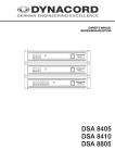
OWNER’S MANUAL
DPA 4245 / DPA 4260 POWER AMPLIFIER
Features
•
2 x 450 watts output power capacity DPA 4245
•
2 x 600 watts output power capacity DPA 4260
•
floating 100 V / 70 V / 25 V power outputs (isolated outputs)
•
low impedance outputs (direct outputs)
•
bridged mode operation, switchable
•
all outputs are protected against idling and short-circuit
•
mains supply 230 V AC 50/60 Hz
•
POWER REMOTE function
•
service mains switch
•
active ventilation via 2 temperature-controlled DC-fans
•
electronically balanced inputs
•
routing switch for parallel linked operation
•
input gain controls
•
integrated audio limiters
•
power-on switching noise suppression
•
protection circuitry: DC/HF, Back-EMF, output voltage overload limiters, initial inrush current limiter,
output peak current limiter
•
18 dB/oct. LO-cut filter at 45 Hz
•
SIGNAL and LIMIT indication for optical monitoring
•
thermal overload protection for the heat sink and the internal power supply, with PROTECT-function
•
inputs transformers for balanced, floating operation are optionally available
•
XLR-type and binding post clamping input connectors
•
19" frame size, 3 HU
15
CONTENTS
Description . . . . . . . . . . . . . . . . . . . . . . . . . . . . . . . . . . . . . . . . . . . . . . . . . . . . . . . . . . .
Installation Notes . . . . . . . . . . . . . . . . . . . . . . . . . . . . . . . . . . . . . . . . . . . . . . . . . . . . . .
Rear View . . . . . . . . . . . . . . . . . . . . . . . . . . . . . . . . . . . . . . . . . . . . . . . . . . . . . . . . . . .
Inputs . . . . . . . . . . . . . . . . . . . . . . . . . . . . . . . . . . . . . . . . . . . . . . . . . . . . . . . . . . . . . . .
Outputs. . . . . . . . . . . . . . . . . . . . . . . . . . . . . . . . . . . . . . . . . . . . . . . . . . . . . . . . . . . . . .
Specifications. . . . . . . . . . . . . . . . . . . . . . . . . . . . . . . . . . . . . . . . . . . . . . . . . . . . . . . . .
Block Diagram . . . . . . . . . . . . . . . . . . . . . . . . . . . . . . . . . . . . . . . . . . . . . . . . . . . . . . . .
Dimensions . . . . . . . . . . . . . . . . . . . . . . . . . . . . . . . . . . . . . . . . . . . . . . . . . . . . . . . . . .
Warranty . . . . . . . . . . . . . . . . . . . . . . . . . . . . . . . . . . . . . . . . . . . . . . . . . . . . . . . . . . . .
17
18
19
19
20
27
43
44
48
IMPORTANT SAFETY INSTRUCTIONS
The lightning flash with arrowhead symbol, within an equilateral
triangle is intended to alert the user to the presence of uninsulated
“dangerous voltage” within the product’s enclosure that may be of
sufficient magnitude to constitute a risk of electric shock to persons.
The exclamation point within an equilateral triangle is intended to
alert the user to the presence of important operating and maintance (servicing) instructions in the literature accompanying the
appliance.
1.
2.
3.
4.
5.
6.
7.
8.
9.
10.
Read these instructions.
Keep these instructions.
Heed all warnings.
Follow all instructions.
Do not use this apparatus near water.
Clean only with a damp cloth.
Do not block any of the ventilation openings.
Install in accordance with the manufactures instructions.
Do not install near any heat sources such as radiators, heat registers, stoves, or other apparatus that produce heat.
Only use attachments/accessories specified by the manufacturer.
Refer all servicing to qualified service personnel. Servicing is required when the apparatus has been damaged in any
way, such as power-supply cord or plug is damaged, liquid has been spilled or objects have fallen into the apparatus,
the apparatus has been exposed to rain or moisture, does not operate normally, or has been dropped.
For US and CANADA only:
Do not defeat the safety purpose of the grounding-type plug. A grounding type plug has two blades and a third grounding prong.
The wide blade or the third prong are provided for your safety. When the provided plug does not fit into your outlet, consult an
electrican for replacement of the absolete outlet.
IMPORTANT SERVICE INSTRUCTIONS
CAUTION: These servicing instructions are for use by qualified personnel only. To reduce the
risk of electric shock, do not perform any servicing other than that contained in the
Operating Instructions unless you are qualified to do so. Refer all servicing to
qualified service personnel.
1. Security regulations as stated in the EN 60065 (VDE 0860 / IEC 65) and the CSA E65 - 94 have to be obeyed when
servicing the appliance.
2. Use of a mains separator transformer is mandatory during maintenance while the appliance is opened, needs to be
operated and is connected to the mains
3. Switch off the power before retrofitting any extensions, changing the mains voltage or the output voltage.
4. The minimum distance between parts carrying mains voltage and any accessible metal piece (metal enclosure),
respectively between the mains poles has to be 3 mm and needs to be minded at all times.
The minimum distance between parts carrying mains voltage and any switches or breakers that are not connected
to the mains (secondary parts) has to be 6 mm and needs to be minded at all times.
5. Replacing special components that are marked in the circuit diagram using the security symbol (Note) is only permissible
when using original parts.
6. Altering the circuitry without prior consent or advice is not legitimate.
7. Any work security regulations that are applicable at the location where the appliance is being serviced have to be strictly
obeyed. This applies also to any regulations about the work place itself.
8. All instructions concerning the handling of MOS - circuits have to be observed.
Note:
SAFETY COMPONENT (HAS TO BE REPLACED WITH ORIGINAL PART ONLY)
16
DESCRIPTION
Especially designed for permanent installations, the DPA-Series power amplifiers offer performance-consistent and reliable operation of PA-systems with 2 individual loudspeaker lines, each. Therefore,
DPA-Series power amplifiers are most suitable for company intercom, alarm and background music
transmission installations in offices and commercial areas, congregation and sport centers, schools,
houses of worship, hotels, hospitals, shopping malls and super markets, cruise ships, and other similar
applications.
Each power amplifier incorporates two high-performance output transformers. Next to 100 V, 70 V, and
25 V floating outputs, the direct outputs provide the possibility to also drive loudspeaker systems with
low-impedance down to a minimum of 4 ohms. Simultaneous operation of low-impedance speaker
systems and floating loudspeaker lines on a single output channel of the power amplifiers is possible as
well.
The integrated 45 Hz LO-cut filter with 18 dB/oct. slope protects the connected loudspeaker lines from
unwanted ultra-low frequencies.
Comparator circuitry constantly monitors the input and output signals of the power amplifiers and activates
their internal limiters whenever non-linear operation is encountered which reliably protects the connected
loudspeaker systems against overload conditions and clipping, saturation of the power supply transformers, and overvoltage at the outputs. The DPA-Series power amplifiers’ transmission and sound qualities
are absolutely superb. The employed comprehensive dimensioned power supply units with low-interference toroidal transformers ensure that the stated nominal performance specifications are accomplished,
even in most demanding and critical installations. Since the DPA-Series power amplifiers do not employ
V/I-Foldback-Limiter circuits, operation on complex loads up to ±90° phase angles is possible without a
problem.
Quick optical information on the power amplifiers’ momentary operational status is provided through easily
readable LED indicators, individually showing whether a channel is ready for operation, a signal is present
at the output, if any of the limiter circuits and/or one of the protection circuits has been activated.
The inputs are electronically balanced and carried out as XLRF-type and as binding post clamping
connectors as well. Parallel linking the two connector types at the input provides the possibility to utilize
the carried-through signals to feed additional power amplifiers, without the necessity for special split-cables. Both inputs can be optionally retrofitted with input transformers. Through Input Routing switches it is
possible to configure the DPA-Series power amplifiers for stereo, parallel-monaural, or bridged-mode
operation.
The dB-scaled level controls – extremely precise and good to operate potentiometers – are located on
the rear of the appliances. A Ground-Lift switch which helps eliminating ground noise loops by separating
the amplifier circuit ground from the common ground of the enclosure is also to be found on the rear
panels. Conveniently connecting the loudspeaker lines to the power amplifiers is provided through a
binding post strip, where all voltages – 25 V, 70 V, 100 V – and the low-impedance output are present on
individual screw-clamp connectors. The rear panel service mains switches allow turning the power
amplifiers’ power on directly. Using the provided power remote input, remote-start is also possible.
Consistent thermal stability of the power amplifiers is obtained through extremely silent running fans which
are automatically switched stepwise depending on the amplifiers’ operation mode. The front-to-rear air
circulation guarantees trouble-free operation in rack-shelf enclosures of any size.
Several other features of the DPA-Series power amplifiers are revealed within this owner’s manual.
Therefore, please take the time to carefully and entirely read the provided information.
17
Installation Notes
Generally, it is important to install the power amplifier in a way, that ensures unhindered front-to-rear air
circulation.
When installing the power amplifier in a closed rack-shelf system, please make sure that adequate air-flow
is guaranteed. The space between the rear panel of the amplifier and the inner wall of the rack-case has
to be at least 60 mm x 330 mm. A free space of at least 100 mm above the rack-shelf system is needed
to provide sufficient air circulation. Since, during operation, the temperature inside the rack system could
easily rise up to 40° C, the maximum allowable ambient temperatures of the rest of the incorporated
modules and appliances within a specific rack-shelf system have to be taken into careful consideration.
When mounting the power amplifier inside of a closed rack system, it is recommended to use special rack-rails or
optionally available rack-mount ears
NRS 90235 (112733) to prevent bending
of the appliance’s front panel.
Note
For maintained trouble-free operation of the appliance, the maximum admissible ambient
temperature of +40°C is not to be exceeded.
The amplifier has to be protected from:
- water drops or splashes
- direct sunlight
- high ambient temperatures and the direct radiation of heat sources
- high humidity and moisture
- heavy dust
- massive vibrations
Moving the amplifier from a cold into a warm environment can result in the occurrence of condensation
on inner parts. Operating the appliance is only permissible after it has accommodated to the altered
temperature (approximately after one hour).
Should any foreign solid parts or liquids inadvertently intrude the enclosure, immediately unplug the device
from the power source and have it checked at a DYNACORD service center, before further use.
Cleaning the appliance should not be performed using chemical solvents or sprays, as this might damage
the finish and could even cause hazard fire.
Before The First Operation
Before switching the amplifier’s power on, the included mains cord has to be connected to a 230 V - 50/60
Hz wall outlet. On the appliance itself, the cord has to be connected to the 3-pole mains socket.
To remotely start the amplifier, it is necessary to connect an external 24 V power source to the terminal
strip POWER REMOTE. Providing correct connection and with an external power supply being present,
the POWER ON indicator will light and the power amplifier is ready for operation.
The mains switch POWER on the rear of the appliance is meant for service and maintenance purposes
only. Through bridging the mains switching relay this option provides the possibility to operate the amplifier
without an external 24 V power supply connected.
Caution The mains switch POWER on the rear of the appliance is only meant for maintenance.
Remotely switching off the device is not possible when the POWER switch is engaged.
The DPA-Series power amplifiers employ power-on switching delays of approximately 2 seconds.
18
Inputs INPUT CHANNEL A&B
With an input sensitivity of 775 mV = 0 dBu and an input impedance of 20
k ohms, the electronically balanced inputs – INPUT CHANNEL A&B – are
meant for the connection of control amplifiers, audio controllers, mixing
consoles, etc.
Peripheral pieces of audio equipment are either connected via the XLRtype input connectors or using the parallel-linked binding posts. For the
latter option you can utilize the supplied screw-plugs. Thus, carrying the
audio signals through to feed additional power amplifiers can be conveniently achieved without the need for special split-cables.
PIN 1:
PIN 2:
PIN 3:
SHIELD
a, +
b, -
The XLR-type input connectors’ pin-assignment is in accordance to the
IEC 268 standard:
In case the controlling device does not supply balanced output connectors,
it is also possible to configure the connectors for unbalanced operation.
Therefore, the common ground (pin 1) has to be connected to the (–) input
(pin 3). The audio signal is now solely fed through the (+) input (pin 2).
So, to be able to entirely make use of all the advantages the electronically
balanced input stage offers – like the suppression of humming and
interference noise – it is beneficial to re-establish balanced input connection whenever possible.
In case floating inputs are needed, the inputs are ready to be retrofitted
with input transformers; one optional available extension kit NRS 90208
(308840) per channel is necessary.
Instructions On How To Install NRS 90208 Extension Kits
•
unplug the power amplifier from the mains
•
detach all screws holding the cover plate of the appliance
•
lift and remove the cover plate
•
disconnect the flat-wire cable of the printed board assembly 81340/1
•
detach all screws holding the printed board assembly 81340/1
•
remove the printed board assembly 81340/1 and unsolder the resistors R106 … R109
•
attach insulators to the input transformers according to the corespondent marks on the printed board
assembly
•
re-assemble the appliance by performing all steps described in the opposite order
19
figure: block diagram input channel A
figure: printed board assembly area
channel A – transformer retrofitting
Level Control
dB-scaled rotary controls for adjusting the power amplifier’s overall amplification. This control should be positioned between the 0 dB and the -6 dB
marks to prevent distortion in source devices. The labeling indicates the
actual attenuation applied to the internal specified factor of amplification.
Input Routing
If the switch is set to parallel/mono, the input connectors CHANNEL A and
CHANNEL B are electrically linked for direct parallel operation. With only
a single audio signal source connected, both channels are driven, while
their volume levels are still individually controlled via the level controls A
and B.
If the switch is set to its dual/stereo position, channels A and B are
separately amplified (two channel or stereo mode).
Power Outputs A&B
The loudspeaker cables are connected to the power amplifier through high-performance binding posts –
with the necessary screw-plugs being supplied. For connection purposes, it is possible to remove the
12-pole terminal plug. Cables with a maximum diameter of 2.5 mm2 can be utilized. To provide flexible
connections, all floating output voltages – 25 V, 70 V, and 100 V (ISOLATED OUTPUTS) – as well as the
low-impedance output (DIRECT OUTPUTS) of both channels are directly accessible.
figure: power outputs of the DPA 4260
20
Power Outputs – AUDIO TRANSFORMER OUTPUTS
The two integrated output transformers convert the power amplifier’s nominal output voltage to the
commonly used loudspeaker line voltage standards – 25 V, 70 V, and 100 V. These voltages are
simultaneously present at the correspondent floating outputs of the binding post strip. The two power
amplifier channels can be operated using any possible output voltage combination. Simultaneous
operation of low impedance loudspeaker systems and floating loudspeaker lines on a single power
amplifier channel is possible as well.
Caution
It is possible that during operation shock-hazard output voltages can be present at the
power output connectors (>34 V peak value). Therefore, the connected loudspeaker
lines have to be installed in accordance to applicable security standards and regulations.
When installing and operating 100 V-loudspeaker networks, compliance to the VDE
regulation DIN VDE 0800 is mandatory.
Especially, if a 100 V-loudspeaker network is included in alarm system applications, all
security standards have to be in accordance to the security class 3 standard. Before the
first operation of the power amplifier, the loudspeaker terminal strip has to be covered
using the supplied protection cover.
Power Outputs - Isolated Outputs 70 V and 100 V
To reduce line attenuation effects when the distance between power amplifier and loudspeaker systems
exceeds 50 meters, it is recommended to employ loudspeaker systems with 100 V or 70 V line
transformers, which also allows conveniently distributing the output power to the individual loudspeaker
systems.
It is possible to connect as many loudspeaker systems until the total power consumption of the
loudspeaker network equals the nominal power handling capacity of the power amplifier; while not
declining the nominal load impedance of the power amplifier outputs.
For details on nominal power handling capacity and nominal load impedance of the amplifier’s individual
power outputs, please refer to the specifications in the appendix.
figure:
example configuration – DPA 4260 with 100 V loudspeaker systems – maximum load
using 30 W / 100 V and 60 W / 100 V loudspeaker systems
21
Power Outputs - Isolated Outputs 25 V
The floating 25 V output is mainly used for driving low impedance loudspeaker systems (4 - 16 ohms).
Because of the effect of line attenuation, the distance between power amplifier and loudspeaker systems
should not exceed 50 meters. It is further important that the total impedance of the entire loudspeaker
network does not decline the nominal load impedance of the 25 V output. For details on the nominal load
impedance of the 25 V output, please also refer to the specifications in the appendix.
figure:
example configuration – DPA 4260 with 8 ohms and 16 ohms loudspeaker systems at
maximum load
Power Outputs – DIRECT OUTPUTS
In addition to the output transformer equipped outputs and for driving low impedance, high performance
loudspeaker systems, the power amplifier’s direct, low impedance outputs are carried out as well, offering
a minimal load impedance of 4 ohms. Each power amplifier channel is capable of simultaneously driving
loads at the direct output and at the isolated output. But it is of major importance that the overall power
consumption of the connected loudspeaker systems or lines does not exceed the output power capacity
of the power amplifier.
Example: If a loudspeaker system with 8 ohms and a nominal power handling capacity of 300 watts is
connected to the DPA 4260 channel A Direct Output, this equals exactly half of the power amplifier’s
output power capacity since the minimal load impedance for each channel is 4 ohms. That leaves the
possibility to utilizes exactly half of the nominal output power capacity of the channel A 100 V output –
which in this example equals 500 watts/2 = 250 watts – to supply a split loudspeaker line. The total
impedance of the loudspeaker line has not to decline 20 ohms*2 = 40 ohms.
figure:
example configuration – DPA 4260 channel A in mixed mode
22
Bridged Mode
Doubling the power amplifier’s output power is accomplished by engaging bridged mode operation, where
the two power amplifier output stages are linked for push-pull operation. In other words, a monaural power
amplifier is “created” offering double the output voltage and double the output power capacity of a single
channel. As a result you are provided with floating 50 V, 140 V, and 200 V as well as with a direct output
with doubled nominal output voltage.
If the BRIDGED-MODE switch is engaged, the audio input signal has to be fed via the CHANNEL A input
while the CHANNEL B input is without function. The signal is internally inverted and the power amplifier
stage B is driven by that inverted signal. The power amplifier stage A is still driven by the unaltered
incoming audio signal. Bridged mode operation is possible with using the isolated and/or the direct outputs.
When using the isolated outputs, bridging the (–) binding posts of channels A and B is mandatory,
using short cables with suitable diameter (1.5 mm2 ... 2.5 mm2)!
Careful consideration of the loudspeaker systems’ correct connection is important in preventing phase
correlation problems. Channel A carries the signal “in phase” and therefore has to be connected to the
(+)-pole of the correspondent loudspeaker system while the loudspeakers (–)-pole has to be connected
to the (+)-output connector of channel B. The output voltage of each power amplifier stage A&B is present
at the binding post strip, but utilization is not recommended because of the negative correlation.
figure:
output connection in 50 V bridged mode operation
*Caution! The bridging cable has to be at least 1.5 mm2 in diameter.
Driving 4 ohms loads at the direct output is not admissible in bridged mode operation. For details on
nominal load impedance and nominal loads of the individual outputs in bridged mode operation, please
refer to the specifications in the appendix. Also in bridged mode, the nominal load impedance is not to be
declined.
23
GROUND Lift Switch
The ground lift switch helps is a perfect means for eliminating possible ground
noise loops. In case the power amplifier is operated together with other
equipment inside of a rack shelf system, the switch should be set to its
GROUNDED position. When using the power amplifier together with other
equipment that operates on different ground potentials, the switch should be
set to UNGROUNDED.
Power On And Remote Control
When the power amplifier is operated via power remote start (standard
operation) an external 24 V power source has to be connected to the POWER
REMOTE terminal strip and the mains switch has to be set to its OFF-position. When correctly connected and with a present supply voltage, the power
amplifier is operational. The fans run for approximately 2 seconds and the
POWER ON-LED on the front panel lights. The mains switch POWER on the
rear of the appliance bridges the mains relay. It is meant for service purposes
only. This allows to operate the power amplifier without the presence of an
external 24 V power source. The current consumption at the POWER
REMOTE input is approximately 25 mA.
Limit Indicator
The indicator lights whenever the integrated limiter is activated. While short
blinking means no problem, the continuously lit LED indicates that the volume
level needs to be reduced to prevent the connected loudspeaker systems
from being damaged by overload.
The audio limiters are capable of controlling overdrive levels of up to 20 dB.
Most other power amplifiers without integrated limiters begin to clip, generating nasty distortion that not only attacks your ears but also lead to damaging
the connected loudspeaker systems by overload. The limiters are activated
only in case of the occurrence of non-linear conditions within the power
amplifier; e. g. signal clipping at the operation voltage limit. The limiters do
not affect the power amplifier’s overall dynamic range.
Signal Indicator
This indicator is lit when the audio signal exceeds –30 dB. In case short-circuits resulting from broken loudspeaker cables are detected or one of the
power amplifier’s protection circuits is activated, the signal indicator is
dimmed.
PROTECT
The PROTECT-LED lights whenever one of the power amplifier’s protection
circuits – thermal overload, RF, DC, Back-EMF – is activated. In PROTECT
mode all loudspeaker lines and output transformers are disconnected via
relays and the power amplifier’s audio inputs are short-circuited to prevent
the connected loudspeaker systems from being damaged. When the power
amplifier enters the PROTECT mode please examine first whether the
appliance is overheated. If this is the case, the front and rear ventilation
louvres are possibly covered, the nominal load impedance has fallen below
the specified minimum value, or a short-circuit occurred at the power output.
When switching the power amplifier on, the PROTECT-LED lights for approximately 2 seconds. This is normal. It signals that the protection circuitry is
in working order.
Power ON Indicator
This LED lights when the power amplifier is connected to the mains and its
power switch is set to the ON-position. If the indicator does not light although
the power amplifier is switched on, the appliance is not connected to the
mains or the primary fuse is blown.
24
Protection Circuitry
The DPA-Series power amplifiers are equipped with extensive protection circuitry:
•
initial current inrush limiter
•
power-on delay
•
RF and DC protection
•
Back-EMF protection
•
limiters for the audio signals
•
output peak-current-limiters
•
thermal overload of the heat sink
•
thermal overload of the mains transformer
•
output voltage overload limiters
High-level signals in the low frequency range can drive the output transformers of power amplifiers that
do not provide audio signal limiters into saturation, resulting in nasty distortion and high thermal load of
the power amplification stage. The audio signal limiters of the DPA-Series power amplifiers are designed
to quickly identify the occurring saturation of the core of an output transformer. The level is dynamically
reduced to a value, that stays just below the point of where the saturation starts. The Limit-LEDs on the
front panel indicate that the limiters have been activated. Despite the protection that is provided through
the audio signal limiters, the Limit-LEDs should not light over a longer period of time. Please, locate the
cause of the faulty operation – e. g. lower the LF-EQ setting at the connected mixing console when at the
same time the input level at the power amplifier is approximately +10 dB above the nominal input level.
The DPA-Series power amplifiers employ integrated Lo-Cut filters at 45 Hz with 18 dB/oct. for each
channel. They protect the loudspeaker systems that are connected via output transformers against
low-frequency audio signals, which, depending on the quality and size of the involved transformers, could
lead to problems with core saturation. In addition to the 45 Hz Lo-Cut filters, the frequency response of
the DPA-Series power amplifiers top margin is set by 30 kHz Hi-Cut filters with 12 dB/oct., preventing
unwanted high-frequency audio signals from being present at the outputs.
25
Mains Operation And Leakage Power
The mains power consumption as well as the leakage power is stated for driving the power amplifier at
different levels. All the values were measured at nominal load via the 100 V output with two channels
driven. The shown values differ only slightly when the appliance is operated at different nominal output
voltages or in the Direct Out mode.
Umains[V]
mains operation at the
100 V output
Imains [A]
Pmains [VA]
Pmains [W]
Pout [W]
Pv [W]
BTU/hr
DPA 4245
idling
230V
0,34
78
47
—
47
160
normal operation (-10 dB)
230V
2,76
635
490
70
420
1430
alarm (-3 dB)
230V
5,54
1274
1040
352
688
2347
nominal conditions
230V
7,45
1714
1420
700
720
2456
idling
230V
0,57
131
80
—
80
273
normal operation (-10 dB)
230V
3,66
842
655
101
554
1890
alarm (-3 dB)
230V
7,34
1688
1370
506
864
2948
nominal conditions
230V
9,86
2268
1900
1000
900
3070
DPA 4260
initial current inrush for both models: < 38 A
Pmains[VA] = apparent power Umains*Imains, Pmains[W] = active power, Pout[W] = output power,
Pv[W] = leakage power, 1BTU = 1055.06 W/s
Fuses
location
pos.
utilization
value
dimensions
standard
rear panel DPA 4245
—-
mains fuse 230V~ AC
T8A 250V
5 x 20 mm
IEC 127
rear panel DPA 4260
—-
mains fuse 230V~ AC
T10A 250V
5 x 20 mm
IEC 127
print 84171/1
F1
power supply
T1A 250V
5 x 20 mm
IEC 127
print 84171/1
F2
power supply
T1A 250V
5 x 20 mm
IEC 127
Extension Kits For The DPA 4245 And The DPA 4260:
NRS 90208 balanced input (input transformer for a single channel)
NRS 90235 1 pair of rack-mount ears
26
Technical Specifications: DPA 4245, DPA 4260
Amplifier at rated conditions, both channels driven, direct outputs with 8Ω loads, isolated outputs with rated load and voltage,
unless otherwise specified.
DPA4245
DPA4260
DUAL MODE
Direct Output
Isolated Outputs
Output Definition
Load impedance or rated output voltage
Rated Load Impedance
isolated outputs only
Maximum Midband Output Power
THD=1%, 1kHz
Maximum Midband Output Voltage
THD=1%, 1kHz, RMS, rated load
Rated Output Power
THD <0.2%, 45Hz ... 20kHz,
>10min. according IEC 268-3
Rated Output Voltage
THD<0.2%, 45Hz ... 20kHz
Maximum RMS Voltage Swing
THD=1%, 1kHz, no load connected
Frequency Response, -3dB, ref.1kHz
LO-Cut-Filter: 18dB/octave, 45Hz
HI-Cut-Filter: 12dB/octave, 30kHz
Voltage Gain
at 1 kHz
Input Sensitivity and Impedance
at rated condition
Slew Rate
Power Bandwith
THD=1%, ref. 1kHz, half power @ rated
load impedance
THD at rated output power,
MBW=80kHz, 1 kHz
IMD-SMPTE
60 Hz, 7 kHz
DIM30
3.15 kHz, 15 kHz
Crosstalk
ref. 1kHz, at rated output power
Input Impedance
20Hz ... 20 kHz, balanced
Damping Factor
at 100Hz / 1kHz, direct outputs only
Insertion Loss
isolated outputs only
Signal to Noise Ratio
Rated output voltage to noise, A-weighted
8Ω
100V
70V
25V
28.5Ω
14Ω
1.8Ω
4Ω
Direct Output
Isolated Outputs
8Ω
100V
70V
25V
20Ω
9.8Ω
1.25Ω
4Ω
240W
450W
410W
400W
390W
330W
600W
590W
580W
570W
44V
42.4V
108V
74.8V
26.5V
51.3V
49V
109.5V 75.4V
26.7V
230W
350W
350W
350W
350W
300W
500W
500W
500W
500W
42.9V
37.4V
100V
70V
25V
49V
44.7V
100V
70V
25V
125 V
87V
31V
121V
88V
32V
44V
45 Hz .... 30kHz
34 dB
34 dB
45 Hz.... 22kHz
42 dB
39 dB
30 dB
52V
45 Hz .... 30kHz
35 dB
35 dB
45 Hz .... 22kHz
42 dB
39 dB
30 dB
0dBu ( 775mV) / 20 kOhm
25 V/µs
45Hz ...50kHz
45Hz .... 25kHz
30 V/µs
45Hz .... 50kHz
45Hz .... 25 kHz
< 0.05%
< 0.1% < 0.2% < 0.3%
< 0.05 %
< 0.1% < 0.2% < 0.3%
< 0.08%
< 0.1% < 0.3% < 0.5%
< 0.08%
< 0.1% < 0.3% < 0.5%
< 0.03%
< 0.2% < 0.2% < 0.2%
< 0.03 %
< 0.2% < 0.3 % < 0.3%
< -80dB
20 kOhm
> 300 / > 200
> 300 / > 200
0.7 dB
0.8 dB
0.9 dB
> 100 dB
27
0.7 dB
0.8 dB
1.1 dB
BRIDGED MODE
Direct Output
Output Definition
8Ω
Load impedance or rated output voltage
Rated Load Impedance
——
isolated outputs only
Rated Output Power
560 W
THD<0.2%, 45Hz ... 20kHz
Maximum Bridged Output Power
900W
THD=1%, 1kHz
GENERELLPower Requirements
Power Consumption
at 1/8 maximum output voltage @ rated load impedance
Protections
Isolated Outputs
Direct Output
Isolated Outputs
200V
140V
50V
8Ω
200V
140V
50V
57Ω
28Ω
3.6 Ω
——-
40Ω
19.6Ω
2.5 Ω
700 W
700 W
700W
600W
1000W
1000W
1000W
820W
800W
780W
1200W 1180W
1160W
1140W
230V / 50Hz...60Hz
690 W
870 W
Audio limiters, High temperature, DC, HF, Back-EMF,
Peak current limiters, Inrush current limiters, Turn-on delay, Output Transformer Saturation Protection
Euro-style, 3pin, detachable or XLR
Euro-style, 12pin, detachable, covered
Front-to-Rear, 3-stage-fans
The appliances are in accordance with EN60065, EN50081-1, EN 50082-1
I
Input Connectors
Output Connectors
Cooling
Regulations
Safety Class
Operating Temperature Range
Mounting Depht with Connectors
Mounting Depht without Connectors
Dimensions (W x H x D)
Weight (net)
+5°C ... +40°C
437 mm
377 mm
483mm x 132.5mm x 382mm
20.5 kg
28
22.5kg