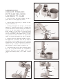
1
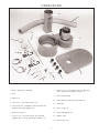
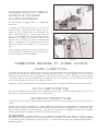
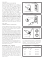
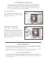
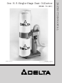
(Model 50-840)
D ATED 10-12-97
PA RT NO. 1347662
'Delta International Machinery Corp. 1997
INSTRUCTION M A N U A L
One H.P.Single-Stage Dust Collector
TA B L E O F C O N T E N T S
SAFETY RULES ................................................................ 3
IMPORTA N T SAFETY RULES F O R D U S T COLLECTO R S .............................. 4
U N PACKING................................................................... 4
A S S E M B LY
Assembling Casters To Base ................................................. 6
Assembling Support Tube And Motor And Blower Assembly To Base ............... 7
Assembling Filter And Dust Collection Bags To Drum ............................ 8
Assembling Dust Intake Hose To Motor And Blower Assembly ..................... 9
CONNECTING MACHINE TO P O W E R S O U R C E
Power Connections ......................................................... 9
Motor Specifications ........................................................ 9
Grounding Instructions ...................................................... 9
120 Volt, Single Phase Operation .......................................... 10
240 Volt, Single Phase Operation .......................................... 10
Extension Cords .......................................................... 10
O P E R ATING C O N T R O L S
On/Off Switch ............................................................. 11
Locking Switch In The OFF Position ........................................ 11
MAINTENANCE
Motor Maintenance ........................................................ 11
W A R R A N T Y .................................................................. 12
2
IMPORTANT SAFETY RULES
W oodworking can be dangerous if safe and proper operating procedures are not followed. As with all machinery, there are certain
hazards involved with the operation of the product. Using the machine with respect and caution will considerably lessen the possibility of personal injury. However, if normal safety precautions are overlooked or ignored, personal injury to the operator may result.
Safety equipment such as guards, push sticks, hold-downs, featherboards, goggles, dust masks and hearing protection can reduce
your potential for injury.But even the best guard won t make up for poor judgment, carelessness or inattention. Always use common
sense and exercise caution in the workshop. If a procedure feels dangerous, don t try it. Figure out an alternative procedure that feels
safer. REMEMBER: Your personal safety is your responsibility.
This machine was designed for certain applications only. Delta Machinery strongly recommends that this machine not be modified
and/or used for any application other than that for which it was designed. If you have any questions relative to a particular application, DO N O T use the machine until you have first contacted Delta to determine if it can or should be performed on the product.
D E LTA INTERNATIONAL MACHINERY C O R P.
M A N A G E R O F TECHNICAL S E RVICES
246 A L P H A DRIVE
PITTSBURGH, PENNSYLVANIA 15238
(IN CANADA: 644 IMPERIAL ROAD, GUELPH, ONTARIO
N1H 6M7)
W ARNING: FAILURE TO F O L L O W THESE RULES
M AY RESULT IN SERIOUS P E R S O N A L INJURY
15. DON T O V E R R E A C H. Keep proper footing and balance
at all times.
1. F O R Y O U R O W N S A F E T Y, READ INSTRUCTION
M A N U A L B E F O R E O P E R ATING T H E TO O L. Learn the
tool s application and limitations as well as the specific
hazards peculiar to it.
16. MAINTAIN TO O L S IN TO P CONDITION. Keep tools
sharp and clean for best and safest performance. Follow
instructions for lubricating and changing accessories.
2. K E E P G U A R D S IN PLACE and in working order.
3. A LW AY S W E A R E Y E PROTECTION.
17. DISCONNECT TO O L S before servicing and when
changing accessories such as blades, bits, cutters, etc.
4. G R O U N D ALL TO O L S. If tool is equipped with threeprong plug, it should be plugged into a three-hole electrical
receptacle. If an adapter is used to accommodate a twoprong receptacle, the adapter lug must be attached to a
known ground. Never remove the third prong.
18. U S E R E C O M M E N D E D ACCESSORIES. The use of
accessories and attachments not recommended by Delta
may cause hazards or risk of injury to persons.
19. R E D U C E T H E RISK O F UNINTENTIONAL S TA R TING. Make sure switch is in OFF position before plugging
in power cord.
5. R E M O V E ADJUSTING KEYS A N D W R E N C H E S. Form
habit of checking to see that keys and adjusting wrenches are
removed from tool before turning it on.
20. N E V E R STA N D O N TO O L. Serious injury could occur
if the tool is tipped or if the cutting tool is accidentally
contacted.
6. K E E P W O R K A R E A C L E A N. Cluttered areas and
benches invite accidents.
7. DON T U S E IN D A N G E R O U S ENVIRONMENT. Don t
use power tools in damp or wet locations, or expose them
to rain. Keep work area well-lighted.
21. C H E C K D A M A G E D PA R T S. Before further use of the
tool, a guard or other part that is damaged should be carefully checked to ensure that it will operate properly and
perform its intended function check for alignment of moving
parts, binding of moving parts, breakage of parts, mounting,
and any other conditions that may affect its operation. A
guard or other part that is damaged should be properly
repaired or replaced.
8. K E E P CHILDREN A N D VISITO R S AW AY. All children
and visitors should be kept a safe distance from work area.
9. M A K E W O R K S H O P CHILDPROOF
with padlocks,
master switches, or by removing starter keys.
10. DON T FORCE TO O L. It will do the job better and be
safer at the rate for which it was designed.
22. DIRECTION O F FEED.Feed work into a blade or cutter
against the direction of rotation of the blade or cutter only.
11. U S E RIGHT TO O L. Don t force tool or attachment to do
a job for which it was not designed.
23. N E V E R L E AV E TO O L RUNNING UNATTENDED. TURN
P O W E R O F F. Don t leave tool until it comes to a complete
stop.
12. W E A R P R O P E R A P PA R E L. No loose clothing, gloves,
neckties, rings, bracelets, or other jewelry to get caught in
moving parts. Nonslip footwear is recommended. Wear
protective hair covering to contain long hair.
24. DRUGS, ALCOHOL, MEDICATION. Do not operate
tool while under the influence of drugs, alcohol or any
medication.
13. A LW AY S U S E SAFETY GLASSES.W ear safety glasses.
Everyday eyeglasses only have impact resistant lenses;
they are not safety glasses. Also use face or dust mask if
cutting operation is dusty.
25. M A K E S U R E TO O L IS DISCONNECTED FROM POWER
SUPPLY while motor is being mounted, connected or reconnected.
14. S E C U R E W O R K. Use clamps or a vise to hold work
when practical. It s safer than using your hand and frees
both hands to operate tool.
26. W ARNING: The dust generated by certain woods and
wood products can be injurious to your health. Always operate machinery in well ventilated areas and provide for proper
dust removal. Use wood dust collection systems whenever
possible.
3
IMPORTA N T SAFETY RULES F O R
D U S T COLLECTO R S
10. D O N O T pull the dust collector by the power cord.
NEVER allow the power cord to come in contact with
sharp edges, hot surfaces, oil or grease.
W ARNING:
Basic precautions should
always be followed when using your dust collector.
To reduce the risk of injury, electrical shock or fire,
comply with the safety rules listed below:
11. D O N O T unplug the dust collector by pulling on the
power cord. A LW AY S grasp the plug, not the cord.
1. R E A D and understand the instruction manual before
operating the dust collector.
12. D O N O T handle the plug or dust collector with wet
hands.
2. D O N O T leave the dust collector plugged into the
electrical outlet. Unplug dust collector from the outlet
when not in use and before servicing, changing bags,
unclogging and cleaning.
13. REPLACE a damaged cord immediately.D O N O T
use a damaged cord or plug. If the dust collector is not
operating properly, or has been damaged, left outdoors
or has been in contact with water, return it to an
Authorized Service Center for service.
3. A LW AY S turn the power switch OFF before unplugging the dust collector.
14. D O N O T use the dust collector as a toy. D O N O T
use near or around children.
4. W ARNING: TO R E D U C E T H E RISK O F ELECTRICAL S H O C K, do not use outdoors or on wet surfaces.
Use for dry pickup only!
15. D O N O T insert fingers or foreign objects into the
dust intake ports. Keep hair, loose clothing, fingers, and
all body parts away from openings and moving parts of
the dust collector.
5. F O L L O W all electrical and safety codes, including
the National Electric Code (NEC) and the Occupational
Safety and Health Regulations (OSHA). All electrical
connections and wiring should be made by qualified
personnel only.
16. D O N O T use the dust collector without the filter bag
and dust collection bag in place and properly secured.
6. D O N O T use the dust collector to pick up flammable
or combustible liquids, such as gasoline. N E V E R use the
dust collector near any flammable or combustible liquids.
17. D O N O T operate the dust collector with unused dust
intake ports uncapped. A LW AY S cover exposed dust
intake ports.
7. U S E the dust collector to pick up wood materials
only. D O N O T use the dust collector to pick up metal
shavings, dust, or parts.
18. PERIODICALLY INSPECT dust and filter bags for
any cuts,rips or tears. NEVER operate the dust collector
with a damaged bag or vacuum hose.
8. NEVER use the dust collector to dissipate fumes
or smoke. N E V E R pick up anything that is burning or
smoking, such as cigarettes, matches or hot ashes.
19. The dust collector is designed for home use or light
commercial duty O N LY!
20. C O N N E C T dust collector to a properly grounded outlet only. See grounding instructions.
9. U S E only as described in this manual. U S E only accessories recommended by Delta.
S AV E THESE INSTRUCTIONS
U N PACKING
Carefully unpack the dust collector from the shipping container.
W ARNING: D O N O T C O N N E C T T H E D U S T C O L L E C TO R TO T H E P O W E R S O U R C E UNTIL T H E
M A C H I N E IS C O M P L E T E LY A S S E M B L E D A N D Y O U H AV E R E A D A N D U N D E R S TA N D T H E
ENTIRE OWNER S M A N U AL.
Figures 2 illustrates the components after they are removed from the shipping container.
4
U N PACKING
14
15
13
1
12
11
10
5
9
2
8
7
4
3
6
Fig. 2
1 -Motor and Blower assembly
8 -5/16-18 x 1/2 hex head screws for mounting
motor and blower assembly to base (4)
2 -Base
9 -Dust collection bag
3 -Casters (4)
10 -Dust collection and filter bag clamps (2)
4 -10-24 x 3/8
pan head screws (16)
11 -Filter bag
5 -5/16-18 hex nut, lockwasher and flat washer for
mounting filter bag support rod
12 -Hose clamps (2)
6 -Open-end wrench
13 -Filter bag support rod
7 -1/4-20 x 1/2 hex head screws for mounting
support tube to motor and blower assembly (3)
14 -Support tube
15 -Dust intake hose
5
A S S E M B LY
ASSEMBLING CASTERS TO B A S E
Turn base (A) Fig. 3, over.Align four holes (B) in caster with holes at the corner of the base
and assemble caster (C) to base with four pan head screws (D). Assemble the remaining three
casters (C) Fig. 4, to the base in the same manner.
B
A
C
D
Fig. 3
C
C
Fig. 4
6
ASSEMBLING
SUPPORT TUBE A N D
M O TO R A N D B L O W E R
A S S E M B LY TO BASE
B
A
C
1. Place the motor and blower assembly (A) Fig. 5,
upside down on a sturdy supporting surface.
Fig. 5
2. Find the support tube (B) Fig. 5, and three 1/2 inchlong hex head screws (C).
B
3. Carefully place support tube (B) Fig. 6, over the motor
impellers (D). Align three holes (E) Fig. 6, in support tube
(B) with three holes in the motor casting, two of which are
shown at (F) and fasten support tube (B) to motor and
blower assembly (A) with three 1/2 inch-long screws
(C) Fig. 7. Warning label (K) Fig. 7, should be positioned
over the on/off switch (L) when support tube (B) is properly positioned as shown. NOTE: Do not tighten three
screws, two of which are shown at (C) Fig. 8, at this time.
E
D
F
E
A
F
4. Carefully turn motor and blower assembly (A) Fig. 8,
with support tube (B) attached, right side up. Align the
four holes in the feet of support tube (B) Fig. 8, with four
threaded holes (K) in base and fasten motor and blower
assembly (A) Fig. 9, to base (L) with four 5/16-18 x 1/2
hex head screws, three of which are shown at (M).
Fig. 6
B
5. IMPORTA N T:Make certain motor and blower assembly (A) Fig. 9, is parallel with base (L). If adjustment is
necessary, rotate motor (N) on support tube (B) and
tighten three mounting screws, one of which is shown
at (C).
C
K
L
Fig. 7
N
C
A
L
M
A
K
M
B
L
K
K
B
Fig. 8
Fig. 9
7
ASSEMBLING FILTER
A N D D U S T COLLECTION
B A G S TO D R U M
E
1. Thread 5/16 hex locknut (A) Fig. 10, onto the end
of bag support rod (B). Place lockwasher and flat washer (C) Fig. 10, onto bag support rod (B). Thread rod into
hole (D) and tighten locknut (A) against motor and blower
assembly (E) to hold support rod (B) upright. Height of
support rod can be adjusted after the filter bag is in place.
A
B
D
C
Fig. 10
B
F
H
2. Hook the loop on the top of filter bag (F) Fig. 11, onto
the end of support rod (B).
3. Position open end of filter bag (F) Fig. 11, over the lip
of drum (G). NOTE: It may be necessary to adjust the
height of the drum support rod at this time. If adjustment
is necessary, loosen locknut (A) Fig. 11, and rotate
support rod (B) as needed to obtain proper rod height to
support filter bag (F). Tighten locknut (A) Fig. 11. Insert
locking band (H) through the hem of filter bag (F) and
fasten filter bag to drum by locking clamp (J) as shown
in Fig. 12. IMPORTA N T:Make certain band (H) is
positioned in the channel of drum (G) before locking
clamp (J).
G
A
Fig. 11
H
J
G
Fig. 12
4. Insert remaining locking band (H) Fig. 13, through
hem of dust collection bag (K). Position open end of bag
over the lip of drum (G) and fasten with locking clamp (J).
NOTE: Make certain locking band (H) is positioned in the
channel of drum before locking clamp (J).
G
J
H
K
Fig. 13
8
A
C
ASSEMBLING D U S T INTA K E
H O S E TO M O TO R A N D
B L O W E R A S S E M B LY
The dust collector is supplied with a 4
intake hose.
B
flexible dust
To assemble the dust collection hose to the motor and
blower assembly, loosely attach hose clamp (A) Fig. 14,
around one end of flexible hose (B) and assemble the
hose to dust intake port (C). Tighten hose clamp (A)
Fig. 15, to hold flexible hose (B) on the blower and motor
assembly (D). Assemble the remaining clamp to the
other end of the flexible hose and to the woodworking
machine. IMPORTA N T:Do not operate the dust collector
without the flexible hose assembled to the dust intake
port.
Fig. 14
A
B
Always disconnect dust collector from the power source
before connecting or disconnecting an air intake hose to
or from the blower and motor assembly.
D
Fig. 15
CONNECTING MACHINE TO POWER SOURCE
POWER CONNECTIONS
A separate electrical circuit should be used for your tools. This circuit should not be less than #12 AWG and should be
protected with a 20 amp, time lag fuse. Have a certified electrician repair or replace damaged or worn cord immediately.Before connecting the motor to the power line, make certain the switch is in the OFF position and be sure that
the electric current is of the same characteristics as stamped on the motor nameplate. All line connections should make
good contact. Running on low voltage will damage the motor.
W ARNING: D O N O T EXPOSE THE DUST COLLECTO R TO RAIN O R O P E R ATE THE MACHINE IN DAMP L O C ATIONS.
M O TO R SPECIFICATIONS
The motor of the Model 50-840 Dust Collector is shipped wired for 120 Volts. Before connecting the dust collector to the
power source, make certain the switch is in the OFF position.
G R O U N D I N G INSTRUCTIONS
W ARNING: THIS TO O L M U S T B E G R O U N D E D WHILE IN U S E TO P R O T E C T T H E O P E R ATO R F R O M ELECTRIC
SHOCK.
This dust collector must be grounded. If it should malfunction or break down, grounding provides a path of least resistance for electric current to reduce the risk of electric shock. This dust collector is equipped with a cord having an equipment-grounding conductor and grounding plug. The plug must be inserted into an appropriate outlet that is properly
installed and grounded in accordance with all local codes and ordinances.
W ARNING:
Improper connection of the equipment-grounding conductor can result in a risk of electric
shock. Check with a qualified electrician or service person if you are in doubt as to whether the outlet is properly grounded.
Do not modify the plug provided with the dust collector. If it will not fit the outlet, have a proper outlet installed by a
qualified electrician.
9
120 VOLT,
SINGLE P H A S E O P E R ATION
GROUNDED OUTLET B O X
This tool must be grounded while in use to protect the
operator from electric shock. The motor recommended
for use with your dust collector is shipped wired for 120
Volt, Single Phase, and is equipped with an approved
3-conductor cord and 3-prong grounding type plug to
fit the proper grounding type receptacle, as shown in
Fig. 16. The green conductor in the cord is the grounding
wire. Never connect the green wire to a live terminal.
CURRENT
C A R RYING
PRONGS
GROUNDING BLADE
IS LONGEST O F THE 3 BLADES
A temporary adapter, shown in Fig. 17, is available for
connecting 3-prong grounding type plugs to 2-prong
receptacles if a properly grounded outlet is not available.
The temporary adapter should be used only until a properly grounded outlet can be installed by a qualified
electrician. THIS A D A P T E R IS N O T APPLICABLE IN
CANADA. The green-colored rigid ear, lug, etc., extending from the adapter, is the grounding means and must be
connected to a permanent ground such as to a properly
grounded outlet box, as shown in Fig. 17. Whenever the
adapter is used, it must be held in place with a metal screw.
Fig. 16
GROUNDED OUTLET B O X
GROUNDING M E A N S
ADAPTER
240 VOLT,
SINGLE P H A S E O P E R ATION
Fig. 17
The motor supplied with your dust collector is a dual voltage 120/240 volt motor.The dust collector motor is shipped
ready-to-run for 120 volt operation; however, it may be converted for 240 volt operation.
C U R R E N T C A R RYING PRONGS
The conversion of your dust collector for 240 volt operation
must be done by qualified electrical personnel. Should you
desire to have your dust collector converted for 240 volts,
take your dust collector to your local Authorized Delta
Service Center. Call 1-800-438-2486 for the location of
the nearest Authorized Service Center.The Service Center
will be able to convert your dust collector for 240 volts by
(a) re-wiring the motor for 240 volts; (b) installing a 240 volt
attachment plug to the power supply cord; and (c) replacing the single pole on/off switch shipped with your dust
collector with a double pole switch.
240 VOLT
GROUND PRONG
Fig. 18
The dust collector with a 240 volt plug should only be connected to an outlet having the same configuration as the
plug illustrated in Fig. 18. No adapter is available or should
be used with the 240 volt plug.
A S A PRECAUTION IN ALL CASES, MAKE C E R TAIN
T H E R E C E P TA C L E IN Q U E S T I O N IS P R O P E R LY
GROUNDED. IF Y O U A R E N O T SURE, HAV E A CERTIFIED ELECTRICIAN C H E C K THE RECEPTACLE.
EXTENSION CORDS
TO TA L LENGTH O F
C O R D IN FEET
Use proper extension cords. Make sure your extension
cord is in good condition and is a 3-wire extension cord
which has a 3-prong grounding type plug and a 3-hole
receptacle which will accept the tool s plug. When using
an extension cord, be sure to use one heavy enough to
carry the current of the dust collector.An undersized cord
will cause a drop in line voltage resulting in loss of power
and overheating. Fig. 19, shows the correct size to use
depending on cord length and voltage. If in doubt, use
the next heavier gage. The smaller the gage number, the
heavier the cord.
120 VOLT
25
50
100
150
G A G E O F EXTENSION
C O R D TO U S E
240 VOLT
50
100
200
300
Fig. 19
10
18
16
14
12
AW
AW
AW
AW
G
G
G
G
O P E R ATING C O N T R O L S
F O R O P E R ATO R SAFETY, BEFORE O P E R ATING THE MACHINE, MAKE CERTAIN T H AT THE
D U S T INTA K E H O S E IS A LW AY S ATTA C H E D TO T H E D U S T INTA K E P O R T.T H E R O TATING
FA N L O C ATED INSIDE THE B L O W E R HOUSING IS ACCESSIBLE T H R O U G H THE DUST INTA K E P O R T A N D C A N B E HAZARDOUS. A LW AY S W E A R P R O P E R A P PAREL. DO NOT WEAR
J E W E L RY A N D K E E P FINGERS A N D ALL FOREIGN OBJECTS O U T O F THE DUST INTA K E
P O R T.F O L L O W THE SAFETY RULES EARLIER IN THIS MANUAL.
ON/OFF SWITCH
The on/off switch is located on the side of the motor.
To turn the dust collector ON, push switch toggle (A)
Fig. 20, upward. To turn the dust collector OFF, push
switch toggle (A) downward.
A
Fig. 20
LOCKING SWITCH IN
T HE OFF POSITION
W e suggest that when the dust collector is not in use,
that the switch (B) be locked in the OFF position. This
can be done by grasping the switch toggle (A) Fig. 21,
and pulling it out of the switch (B) as shown. With the
switch toggle (A) Fig. 21, removed, the switch will not
operate. However, should the switch toggle (A) be removed while the dust collector is running, it can be
turned OFF once, but cannot be restarted without
inserting the switch toggle.
B
A
Fig. 21
MAINTENANCE
NOTE: Before any maintenance or service is performed, be sure the unit is disconnected from the power
source to prevent accidental starting. All servicing other than the items recommended in this Instruction
Manual should be performed by an authorized service facility.
When storing your dust collector, remove power supply cord from the electrical outlet. Coil the cord neatly
and place it off the floor on the base of the dust collector to eliminate potential cord damage.
M O TO R MAINTENANCE
Removing dust and dirt: Blow off motor with low pressure air to remove dust or dirt. Air pressure above 50
P.S.I. should not be used as high pressure may damage insulation and blow dirt under loosened tape. The
operator peforming this cleaning function should always wear eye protective goggles. Dust can cause excessive insulation temperatures.
11
Delta Building Trades and Home Shop Machinery
Two Year Limited Warranty
Delta will repair or replace, at its expense and at its option, any Delta machine, machine part, or machine
accessory which in normal use has proven to be defective in workmanship or material, provided that the
customer returns the product prepaid to a Delta factory service center or authorized service station with
proof of purchase of the product within two years and provides Delta with reasonable opportunity to verify the alleged defect by inspection. Delta may require that electric motors be returned prepaid to a motor
manufacturer s authorized station for inspection and repair or replacement. Delta will not be responsible
for any asserted defect which has resulted from normal wear, misuse, abuse or repair or alteration made
or specifically authorized by anyone other than an authorized Delta Service facility or representative.
Under no circumstances will Delta be liable for incidental or consequential damages resulting from defective products. This warranty is Delta s sole warranty and sets forth the customer s exclusive remedy, with
respect to defective products; all other warranties, express or implied, whether of merchantability, fitness
for purpose, or otherwise, are expressly disclaimed by Delta.
Printed in U.S.A.
12