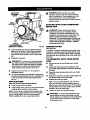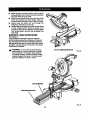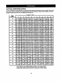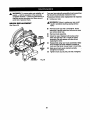
1
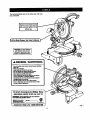
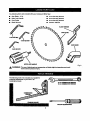
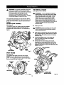
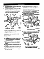
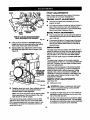
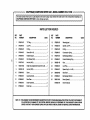
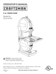
Owner's Manual
10 in.
COMPOUND MITER SAW
Double Insulated
Model No.
315.2121 O0
Save this manual for
future reference
CAUTION:
Read and follow
all Safety Rules and Operating
Instructions before first use of
this product,
Customer Help Line: 1-800-932-3188
•
•
•
•
•
•
Safety
Features
Adjustments
Operation
Maintenance
Parts List
Sears, Roebuck and Co., Hoffman Estates, IL 60179 USA
Visit the Craftsman web page: www.sears com/craftsman
972000-578
8-98
NRTL/C
•
Table of Contents ...........................................................................................................................................
2
•
Warranty and Introduction..............................................................................................................................
2
•
Rules For Safe Operation ...........................................................................................................................
•
Glossary .........................................................................................................................................................
6
•
Product Specificationsand Unpacking ..........................................................................................................
7
•
Labels.............................................................................................................................................................
8
•
Loose Parts and Tools Needed ......................................................................................................................
9
•
Features ..................................................................................................................................................
10-12
•
Adjustments.............................................................................................................................................
13-19
•
Operation.................................................................................................................................................
20-26
•
Maintenance............................................................................................................................................
27-28
•
ExplodedView and Repair Parts List ......................................................................................................
30-37
•
Parts Ordedng / Service ...............................................................................................................................
3-6
38
FULL ONE YEAR WARRANTY
If this productfails due to a defect in material or workmanshipwithin one year from the date of purchase,
Sears will repair it free of charge.
Contact a Sears Service Center for repair.
If this productis used for commercial or rental purposes, this warranty applies only for 90 days from the date
of purchase.
This warranty gives you specificlegal dghts, and you may also have other rightswhich vary from state to state.
Sears, Roebuck and Co., Dept. 817WA, Hoffman Estates, IL 60179
Yoursaw has many features for makingcuffing
operationsmore pleasant and enjoyable. Safety,
performanceand dependability have been giventop
pdodty ih the design of this saw making it easy to
maintain and operate,
,_
Look for this symbol to point out important
Your safety is involved.
_IL
CAUTION: Carefullyread through this entire
owner's manual:beforeusing your new saw. Pay
close attention to the Rules For Safe Operation,
and all Safety Alert SymbolsincludingDanger,
Warning and Caution. If you use your saw
properlyand onlyfor what it is intended, you will
enjoyyears of safe, reliable service.
safety precautions.
It means attentionlH
_lb WARNING:
The operation of any powertool can resultin foreignobjects being thrown into your eyes,
which can result in severe eye damage. Before beginningpower tool operation, always
wear safety gogglesor safety glasses with side shields and a full face shield when needed.
We recommend Wide _sion Safety Mask for use over eyeglasses or standard safety
glasses with side shlel(Js,available at Sears Retail Stores.:
2
Thepurposeof safetysymbolsIsto attractyourattention
to possible dangers. The safety symbols, and
the explanations with them, deserve your careful attention and understanding. The safety warnings do
not by themselves eliminate any danger. The Instructions or warnings they give are not substitutes for
proper accident prevention measures.
SYMBOL
&
MEANING
SAFETY ALERT SYMBOL:
Indicates danger, warningor caution. •ey be used in conjunctionwith other symbolsor pictographs.
A
DANGER: Failure to obey a safety waming will resultin sedous injuryto yourseffor to others.
Always follow the safety precautionsto reduce the dsk of tire, electricshock and personalinjury.
A
WARNING: Failureto obey a safety waming can resultIn sadous injuryto yourseffor to others.
Always follow the safety precautionsto reducethe dskof fire, electdc shock and personal injury.
&
CAUTION: Failureto obey a safety waming may resultIn propertydamage or personal injuryto
yourseffor to others. Always follow the safety precautionsto reducethe flsk of fire, electricshock
and personal injury.
NOTE:
Advisesyou of informationor instructionsvital to the operationor maintenanceof the equipment.
DOUBLE
INSULATION
Double insulationis a concept in safety, in electric
power tools,which eliminates the need for the usual
thrae-wira groundedpower cord. All exposed metal
parts are isolated from intemal metal motor
componentswith protectinginsulation.Double
insulatedtoolsdo not need to be grounded.
_k
WARNING: Do not attempt to operate this tool
until you have read thoroughlyand understand
completely all instructions,safety rules, etc.
contained in this manual. Failure to complycan
result in accidents involvingfire, electdc shock,
or serious personal injury. Save owner's manual
and review frequently for continuingsafe
operation, and instructingothers who may use
this tool.
IMPORTANT
Servicingrequiresextreme care and knowledgeof the
system and shouldbe performed only by e qualified
sawica technician. For servicewe suggestyou retum
the tool to your nearest Sears store for repair.Always
use odginalfactory replacement parts when servicing.
KEEP THE WORK AREA CLEAN. Clutteredwork
areas and work benches invite accidents. DO
NOT leave tools or pieces of wood on the saw
while it is in operation.
•
READ ALL INSTRUCTIONS
KNOW YOUR POWER TOOL. Read the owner's
manual carefully. Learn the saw's applications
and limitationsas well as the specific potential
hazards related to this tool
GUARD AGAINST ELECTRICAL SHOCK BY
PREVENTING BODY CONTACT WITH
GROUNDED SURFACES. For example; pipes,
radiators, ranges, refdgerator enclosures.
KEEP GUARDS IN PLACE and in good working
order.
REMOVE ADJUSTING KEYS AND
WRENCHES. Get in the habit of checking to see
that hex keys and adjustingwrenches are
removed from tool before fuming on saw.
DO NOT USE IN DANGEROUS ENVIRONMENTS. Do not usa powertools near gasolineor
other flammable liquids,in damp or wet locations,
or expose them to rain. Keep the work area well
lit.
KEEP CHILDREN AND VISITORS AWAY. All
visitorsshould wear safety glasses and be kepta
safe distancefrom work area. Do not let visitors
contact tool or extension cord while operating.
•
MAKE WORKSHOP CHILD-PROOF with padlocksand master switches,or by removingstarter
keys.
•
DO NOT FORCE THE TOOl- It will do the job
better and safer at the rate for which it was
designed.
•
USE THE RIGHT TOOL. Do not force the tool or
attachment to do a job it was not designed for.
Don't use it for a purposenot intended.
RULES
FOR SAFE
OPERATION
(Continued)
USE THE PROPER EXTENSION CORD. Make
sure your extension cord is in good condition.
When using an extension cord, be sure to use
one heavy enough to carry the current your
productwill draw. An undersizedcord will cause
a drop in line voltage resultingin loss of power
and overheating.A wire gage size (A,W.G.) of at
least 14 is recommendedfor an extension cord
25 feet or less in length. If in doubt,use the next
heavier gage. The smaller the gage number,the
heavier the cord.
function. Check for alignmentof moving pads,
bindingof moving part==,breakage of parts,
mountingand any other conditions that may
affect its operation.A guard or other part that is
damaged must be propady repaired or replaced
by a qualified service technicianat a Sears store
to avoid dsk of personal injury.
NEVER LEAVE TOOL RUNNING UNATTENDED. TURN THE POWER OFF. Do not
leave tool until it comes to a complete stop.
INSPECT EXTENSION CORDS PERIODICALLY and replace if damaged.
DRESS PROPERLY. Do not wear loose clothing,
gloves, neckties, dngs, bracelets, or other
jewelry. They can get caught and drew you into
moving parts. Rubber gloves and nonsliptootwear are recommended when workingoutdoors.
Ais0 wear protective hair covedng to contain long
hair.
M
RRMLY CLAMP OR BOLT your miter sew to a
workbenchor table at approximatelyhip height.
M
USE ONLY CORRECT BLADES. Do not use
blades with incorrectsize holes; Never use blade
washers or blade bolts that are defec_ve or
incorrect.The maximum blade capacity of your
saw is 10 in.
KEEP BLADES CLEAN, SHARP AND WITH
SUFFICIENT SET. Sharp blades minimize
stallingand kickback.
ALWAYS WEAR SAFETY GLASSES WITH
SIDE SHIELDS. Everyday eyeglasses have only
impact-resistantlenses; they are NOT safety
glasses.
DO NOT REMOVE THE SAW'S BLADE
I
GUARDS. Never operate the sew with any guard
or cover removed. Make sure all guardsare
operating propady before each use.
PROTECT YOUR LUNGS. Wear a face or dust
mask if the cuttingoparetlon is dusty,
KEEP HANDS AWAY FROM CUTTING AREA.
Keep handsaway from blades. Do not reach
underneath work or around or under the blade
while blade is rotating. Do not attempt to remove
cut matedal when blade is moving.
PROTECT YOUR HEARING. Wear headng
protectiondudng extended padods of oparetion.
SECURE WORK. Use clamps or a vise to hold
work when practical. I_ssafer than using your
hand and It frees both hands to operete tool.
_1= WARNING:
DO NOT OVERREACH. Keep properfooting and
balance at all times.
Blade coastsafter turn off.
DO NOT ABUSE CORD. Never yank cord to
disconnectitfrom receptacle. Keep cord from
heat, oil, and sharp edges.
MAINTAIN TOOLS WITH CARE. Keep tools
sharp and clean for borer and safer pedormanca. Follow instructionsfor lubricatingand
changing accassodes.
DISCONNECT ALL TOOLS. When not in use,
before servicing,or when changing attachments,
blades, bits, cutters, etc., all toolsshouldbe
disconnected.
M
INSPECT TOOL CORDS PERIODICALLY and if
damaged, have repairedby a qualifiedservice
technicianat a Sears store. Stay constantly
aware of cordlocationand keep it well away
from the rotatingblade.
M
USE OUTDOOR EXTENSION CORDS. When
tool is used outdoors,use only extension cords
with approvedground connection that are
intended for use outdoors and so marked.
M
DO NOT USE TOOL IF SWITCH DOES NOT
TURN IT ON AND OFF. Have defective switches
replaced by a qualified service technician at a
Sears store.
AVOID ACCIDENTAL STARTING. Be sure
switch is off when plugging in.
USE RECOMMENDED ACCESSORIES. The
use of improper accessoriesmay cause dsk of
injury.
NEVER STAND ON TOOL. Sedous injurycould
occur if the tool is tipped or ifthe blade is unln.tanUonailycontacted.
KEEP TOOL DRY, CLEAN, AND FREE FROM
OIL AND GREASE. Always use a clean cloth
when cleaning. Never use brake fluids, gasoline,
petrolaum-based products,or any solventsto
clean tool.
CHECK DAMAGED PARTS. Before further use
of the tool, a guard or other part that is damaged
shouldbe carefully checked to determine that it
willoperate properly and performits intended
4
RULES
FOR SAFE
OPERATION
(Continued)
ALWAYS SUPPORT LONG WORKPIECES to
minimize risk of blade pinchingand kickback.
Saw may slip, walk, or slide while cuffing long or
heavy boards.
NEVER reach to pick up a workpieca, a piece of
scrap, or any_ing else that is in or near the
cutting path of the blade.
AVOID AWKWARD OPERATIONS AND HAND
POSITIONS where a sudden slip could cause
your hand to move into the blade. ALWAYS
make sure you have good balance. NEVER
operate your miter sew on the floor or in a
crouched position.
BEFORE MAKING A CUT, BE SURE ALL
ADJUSTMENTS ARE SECURE.
GUARD AGAINST KICKBACK. Kickbackoccurs
when the blade stalls rapidlyand workplace is
driven back towardsthe operator, it can pull your
hand intothe blade resultingin serious personal
injury. Stay out of blade path and turnswitch off
immediately if blade bindsor stalls.
•
NEVER stand or have any part of your body in
line with the path of the sew blade.
•
ALWAYS release the power switch and allow the
sew blade to stop rotatingbefore raisingit out of
the workpiece.
AVOID CUl'nNG NAILS. Inspectfor and
remove all nails from lumber before cutting.
DO NOT TURN THE MOTOR SWITCH ON AND
OFF RAPIDLY. This could cause the sew blade
to loosen and could creata a hazard. Should thla
ever occur, stand clear and allow the sew blade
to come to a completestop. Disconnectyour sew
from the power supplyand securely retlghtenthe
blade bolt.
ALWAYS USE A CLAMP to secure the workpiece when possible.
NEVER TOUCH BLADE or other moving parts
dudng use.
NEVER START A TOOL WHEN THE BLADE IS
IN CONTACT WITH WORKPIECE. Allow motor
to come up to full speed before startingcut.
REPLACEMENT PARTS. All repairs,whether
electrical or mechanical,shouldbe made by
qualified service technician at a Sears store.
MAKE SURE THE MITER TABLE AND SAW
ARM (BEVEL FUNCTION) ARE LOCKED IN
POSITION BEFORE OPERATING YOUR SAW.
Lock the miter table by securelytighteningthe
miter lock handle. Lock the saw arm (bevel
function)by securely tighteningthe bevel lock
knob.
,_
NEVER USE A LENGTH STOP ON THE FREE
SCRAP END OF A CLAMPED WORKPIECE.
NEVER hold onto or bind the free scrap end of
the workpiece in any operation.If a work clamp
and length stop are used together, they must
both be installed on the same side of the sew
table to prevent the sew from catching the loose
and and kicking up.
WARNING: When servicinguse only identical
Craftsman replacement parts. Use of any other
parts may create a hazard or cause product
damage.
NEVER USE IN AN EXPLOSIVE ATMOSPHERE. Normal sparkingof the motor could
Ignitefumes.
NEVER leave the miter sew unattendedwhile
connected to a power source.
POLARIZED PLUGS. To reduce the dsk of
electdc shock_this tool has a polarized plug (one
blade is wider than the other). This plug will fit in
a poladzed outletonly one way. If the plug does
not fit fully in the outlet, reverse the plug. If it still
does not fit, contact a qualified aiectdcian to
install the properoutlat. Do not change the plug
in any way.
NEVER cut more than one piece at aurae. DO
NOT STACK more than one workplece on the
sew table at a time.
NEVER PERFORM ANY OPERATION "FREEHAND". Always place the workpiecato be cut on
the miter table and positionit firmlyagainst the
fence as a backstop. Always use the fence.
IF ANY PART OF THIS MITER SAW IS MISSING or shouldbreak, bend, or fail in any way, or
should any electricalcomponent fail to perform
properly,shut off the power switch, remove the
miter saw plugfrom the power source and have
damaged, missing,or failed parts replaced
before resumingoperation.
NEVER hand hold a workpiscathat is too small
to be clamped. Keep handsclear of the no hands
zone.
NEVER reach behind, under, or withinthree
inches of the blade and its cuttingpath with your
hands and fingers for any reason.
DO NOT OPERATE THIS TOOL WHILE UNDER THE INFLUENCE OF DRUGS, ALCOHOL,
OR ANY MEDICATION.
5
RULES
•
ffi
FOR SAFE OPERATION
(Continued)
ALWAYS STAY ALERT! Do not allowfamiliarity
(gained from frequent use of your saw) to cause
a careless mistake. ALWAYS REMEMBER that
a careless fraction of a second is sufficientto
•
MAKE SURE THE WORK AREA HAS AMPLE
LIGHTING to see the work and that no obMtructions will interfere with safe operation BEFORE
performingany work using your saw.
inflictsevere injuPJ.
•
ALWAYS TURN OFF SAW before disconnecting
it, to avoid accidental startingwhen m-connecting to power supply.
ffi
SAVE THESE INSTRUCTIONS. Refer to them
frequently and use to instructother users. If you
loan someone this tool, loan them these instruc-
STAY ALERT AND EXERCISE CONTROL
Watch what you are doing and use common
sense. Do not operate tool when you are tired,
Do not rush.
Miens also.
SAVE THESE INSTRUCTIONS
Arbor
The shaft on which a blade or cuttingtool is mounted.
Bevel Cut
A cutting operation made with the blade at any angle
other than 90" to the miter table,
Crosscut
A cuffing or shaping operation made across the grain
of the workpiece.
Compound Miter Cut
A compound miter cut is a cut made using a miter
angle and a bevel angle at the same time.
Freehand
Performinga cut without using a fence, miter gage,
fixture, work clamp, or other proper device to keep the
workplece from twisting or moving dudng the cut.
Gum
A sticky, sap based residue from wood products,
Mlter Cut
A cutting operation made with the blade at any angle
other than 90" to the fence.
Resin
A sticky, sap base substancethat has hardened.
Revolutions Per Minute (RP•)
The number of turns completed by a spinningobject
in one minute.
Saw Blade Path
The area over, under, behind, or in front of the blade.
As it applies to the workplece, that area whichwill be,
or has been, cut by the blade.
Set
The distance that the tip of the sawblede toothis bent
(or set) outward from the face of the blade.
I
Throw-Back
Throwing of a workplece in a manner similarto a
kickback. Usually associatedwith a cause other than
the kerf dosing, such as a workpisce not being
against the fence, being dropped intothe blade, or
being placed inadvertentlyin contact with the blade.
Through Sawing
Any cutting operation where the blade extends
completely through the thicknessof the workplace.
Workplece
The item on whichthe cuffingoperation is being done.
The surfaces of a workpleca are commonly referred to
as faces, ends, and edges.
Zero Clearance Throat Plate
A plasticthroat plate inserted In the mitertable that
allows for blade clearance. When:you make your first
cut with your compound miter sew, the sew blade cuts
a slot through the throat plate the exact width of the
blade. This providesfor a zero clearance kerf that
minimizesworkpisca taar-out.
No Hands Zone
The area between the marked lines on the left and
dght side of the miter table base. This zone is
identified by no hands zone labels placed inside the
marked lines on the miter table base.
BladeDiameter
BladeArbor
NoLoadSpeed
Rating
Input
NetWeight
10in. CuttingCapacity
withMiterat0°/Bevel
0°:
5/8in.
5-3/4in.Wx 2-5/8in.T
5000RPM Maximum
CuttingCapacity
withMiterat45°/Bevel
0°:
4-1/4in.Wx 2-5/8in.T
120Volts,60Hz-ACOnly
15Amperes Maximum
CuttingCapacity
withMiterat0°/Bevel
45°:
5-3/4in.Wx1-7/8in.T
32Ibs.
Maximum
Cutting
Capacity
withMiterat45°/Bevel
45°:
4-1/4in.Wx 1-7/8in.T
YourCompound
MiterSawhasbeenshipped
completely
assembled except for the blade, miter lock
Do not discard the packing materials untilyou
have carefully inspectedthe saw, identifiedall
loose parts, and setisfa_odly operated your new
handle, and dust guide.
saw.
_lb WARNING: If any parts are missing,do not
operate this tool until the missingparts are
replaced. Failure to do so could result in possible
serious porsonal injury.
•
Your saw has been shippedwith the saw arm
locked in the down position. To release sew arm,
push down on top of saw arm and pullout the lock
pin. See Figure 4.
•
Remove all loose parts from the carton. Separate
and checkwith the list of loose parts. See Rgure 2.
•
•
Remove the packing materialsfrom around your
saw.
Lift the saw arm by the handle. Hand pressure
shouldremain on the sew arm to prevent sudden
rise upon release of the lock pin.
•
•
Carefully lift saw from the carton and place it on a
level work surface. Althoughsmall, this sew is
heavy. To avoid back injury,get help when
needed.
Examine all parts to make sure no breakage or
damage has occurreddudng shipping.
If any parts are damaged or missing,do not attempt to
plug in the power cord and turn the switchon untilthe
damaged or missingparts are obtained and are
installedcorrectly.
The followinglabels are on the miter saw with locations indicated.
Restorelowerbladeguard
andsecurelytightenscrew
beforeuse
e.See
I
DANGER: DO NOT REMOVE
ANY GUARD. USE OF SAW
WITHOUT THIS GUARD WILL
RESULT IN SERIOUS INJURY.
I
A WARNING/ ADVERTENCIA
• ForyourmfMy, madownersmanualbeforeop4rallng
ndtM Hw.
• Wmr eyewOtocUo_
• KeepIvmdsoutof pareofmw blade.
• DonotoplmD HW withoutguardsIn place.
• Do notWslmmzmyoperationI_Vam_.
• Nevw nmchmmmdtheHW blade.
• Turn.oilt_l m_lwzn formw bladetostopbefore
movingwodqdeceor ©h_,_ng _mllngL
• Di.com_t the sawfromthe powersomcebefore
©hanging
bladeor servicing.
• Donotexposeto rainor usein dampplaces.
• ParasuNguddad, lea el manualdelustmzloantes
deuMr I- sierraIngletadora.
10 inch Compound Miter Saw
emllUEIllEJffBI _
RIPllllm1_
MIIz J_ MI,Y 1$i
WARNING:WHeNSeJMCINO,
useONLY
I_,AL
CRAFTSMANREPLACEMENTPARTS.
MODEL 315.'_12100
S_R ..
ASSEMBLED
INMmO¢O
SEARS,'/IOEBUCK
ANOOC_ I
_
I
, Customer Help Line 1-800-932-3188
Rg. 1
8
Thefollowing
itemsareincluded
withyourCompound
MiterSaw:
•
Saw Blade - 10 in.
•
5 mm Hex Key Wrench
•
Miter Lock Handle
•
6 mm Hex Key Wrench
•
•
DustGuide
Blade Wrench
•
•
8mmHexKeyWrench
Owner's Manual
BLADEWRENCH
SAWBLADE
8 mmHEXKEY
6 mmHEXKEY
p
O
DUSTGUIDE
5 mmHEXKEY
MITERLOCKHANDLE
Fig. 2
_i,
WARNING:
The use of attachmentsor eccessodes not Ilstad mightbe hazardousand could
cause serious personal injury.
The followingtools (not included)are needed for
checking adjustmentsof your saw or for
installingthe blade:
%D
17mmCOMBINATION
WRENCH
10mmCOMBINATION
WRENCH
FRAMINGSQUARE
PHILUPSSCREWDRIVER
KNOW
YOUR
COMPOUND
MITER
SAW
See Figure 3.
Before attempting to use your saw, familiarize yourself
with all operatingfeatures and safety requirements.
WARNING: Do not allow familiaritywith your
saw to make you careless. Remember that a
careless fraction of a second is sufficientto inflict
severe injury.
CUTTING
CAPACITIES
When the miter angle (miter table) Is set at O° and
the bevel angle Is set at 0°:
Your saw will cut materials up to a maximum of
5-3/4 in. wide X 2-5/8 in. thick.
When the miter angle (miter table) Is set at 45° and
the bevel angle Is set at 0°:
Your saw will cut matsdals up to a maximum of
4-1/4 in. wide X 2-5/8 in. thick.
When the miter angle (miter table) Is set at O° and
the bevel angle is set at 45°:
15 AMP MOTOR
Your saw has a powerful 15 amp motorwith sufficient
power to handle tough cutting jobs. It is made with all
ball beadngs, and has extemally accessiblebrushes
for ease of servicing.
Your saw will cut materials up to a maximum of
5-3/4 in. wide X 1-7/8 in. thick.
10 in. BLADE
Your saw will cut materials up to a maximum of
4-1/4 in. wide X 1-7/8 in. thick.
A 10 in. saw blade is included with your compound
miter saw. It will cut matedais up to 2-5/8 in. thick or
5-3/4 in. wide, dependingupon the thickness of the
material and the settingat which the cut is being
made.
When the miter angle (miter table) Is set at 45 ° and
the bevel angle is set at 45°:
SWITCH
L_K_LEVER
UPPER
BLADEGUAND
SWITCHTRIGGER
DUSTGUIDE
BLADEGUARD
BEVEL
LOCKKNOB
MITERTABLE
)HANDS
ZONELABEL
"NOHANDSZONE"
ZEROCLEARANCE
'LATE
LOCKPLATE
MITER .
CONTROLARM LOCKHANDLE
Posmvz_oP(_
Fig. 3
10
CARRYING
SPINDLE
HANDLE
Sea Figure 4.
For conveniencewhen carryingor transportingyour
miter saw from one place to another, a carrying
handle has been provided on top of the saw arm as
shown in figure 4. To transport, turn off and unplug
your saw, then lower the saw arm and lock it in the
downposition.Lock saw arm by depressingthe lock
pin.
LOCK
BUTTON
See Figure 5.
A spindle lock button has been providedfor locking
the spindle which stops the rotationof the blade in
your saw. Depress and hold the lock buttonwhile
installing,changing, or removingblade.
LOCK-OFF
SPINDLE
LOCKBuI"rON
CARRYING
HANDLE
LOCK
PIN
SWITCH,
TRIGGER
SAW
ARM
Rg. L
TRIGGER
LOCK
See Figure 6.
MITERLOCK
HANDLE
SAWARM
LOCKEDIN DOWNPOSITION
MITER
LOCK
Fig. 4
HANDLE
Sea Figure 4.
To prevent unauthodzed usa of your compound miter
saw, we suggest that you disconnectit from the power
supply and lock the switchin the off position.To lock
the switch, install a padlock throughthe hole in the
switch tdggar. A lock with a shackle up to 13/64 in.
diameter may be used. When the lock is installedand
locked, the switch is inoperable. Store the padlock key
in another location.
The!miter lock handle securely locksyour saw at
desired miter angles.
LOCK-OFF
See Figure 5.
LEVER
The switch tdggar is equipped with a lock-offlever to
reduce the possibilityof accidental starting.The lockoff lever must be pressed down with the palm of your
hand to tum saw on. Once the saw is on, the lock-off
lever can be released, The spdng loaded lever will
spdng back intothe lock-offpositionwhen the switch
tdgger is released.
SWITCH
TRIGGER
Fig. 6
11
POSITIVE
STOPS
ON MITER
TABLE
Positivestops have been provided st 0 °, 22-1/2 ° and
45 o. The 22-1/2° and 45 ° positive stops have been
providedon both the left and right side of the miter
table.
BEVEL
LOCK
I
KNOB
The bevel lookknob securely locks your compound
miter sew at desired bevel angles. Positive stop
adjustmentscrews have been provided on each side
of the sew arm. These adjustment screws are for
making fine adjustments at 0° and 45°. See pages 18
and 19.
ELECTRIC
1
7/lr _.IIOLE 1?3/lr
BRAKE
31_31"
An aiectdc brake has been provided to quicklystop
blade rotationafter the switch is released.
Fig. 7
FENCE
ELECTRICAL
The fence on your compound miter sew has been
providedto hold your workpleca securely against
when making all cuts.
SELF-RETRACTING
GUARD
LOWER
Your saw has a precisionbuilt aiectdc motor. It should
be connected to a power supply that Is 120 volts,
60 Hz, AC only (normal household current). Do not
operate this tool on directcurrent (DC). A substantial
voltage drop will cause a loss of power and the motor
willoverheat. If your tool does not operate when
plugged into an outlet, double-checkthe power
supply.
BLADE
The lower blade guard is made of shock-resistant,
see-throughplasticthat providesprotectionfrom each
side of the blade. It retracts over the upper blade
guard as the saw is lowered intothe workplace.
MOUNTING
See Figure 7.
HOLES
j_
Yourcompound miter saw should be permanently
mounted to a firm supportingsurface such as workbench. Four 7/16 in. bolt holes have been providedin
the saw base for this purpose. Each of the four
mounting holes shouldbe bolted securely using7/16
in. machine bolts, look washers, and hex nuts (not
Included),Boltssh,ould be of sufficient length to
accommodate the'saw base, lookwashers, hex nuts,
and the thicknessof the workbench.
WARNING: The operation of any saw can
result in foreign objects being thrown intoyour
eyes, which can resultin severs eye damage.
Before starting power tool operation,always
wear safety gogglesor safety glasses with side'
shields and a full face shield when needed. We
recommend wide vision safety mask for use over
eyeglasses or standard safety glasses with side
shields.
_1= WARNING: Do not attemptto modifythis tool or
create acceesodes not recommendedfor use
with this tool. Any such alterationor modification
is misuse and could resultin a hazardous
condition leadingto possible sedous personal
injury.
Tightenall four bolts securely.
The hole patternfor an 18 in. x 24 in. workbench is
shownin Figure 7. Carefully check the workbench
after mounting to make sure that no movement can
occurduring use. If any tipping,sliding,or walking is
noted, secure the workbenchto the flour before
operating.
_l,
CONNECTION
WARNING: Always make sure your compound
miter saw is securely mounted to a workbench or
an approved workstand. Failure to do so could
resultin an accident resulting in possible sedous
personalinjury.
12
_k
TO INSTALL
BLADE
See Figures 10, 11, and 12.
WARNING: To prevent accidental startingthat
could cause possiblesedous personal injur/,
assemble all parts to your saw before connecting
itto power supply. Saw shouldnever be
connected to power supplywhen you are
assembling parts, making adjustments,installing
or removingblades, or when not in use.
A
As mentioned previouslyyour saw has been factory
assembled and adjusted. The miter lock handle, dust
guide, and blade are the only parts that have to be
installed,
MITER
LOCK
See Figure 8.
HANDLE
•
To installthe miter lock handle, place the threaded
stud on the end of the miter lock handle intothe
threaded hole in the control arm. Turn clockwiseto
tighten,
A
WARNING: A 10 in. blade is the maximum
blade capacity of your saw. Never use a blade
that is too thick to allow outer blade washer to
engage with the flats on the spindle. Larger
blades willcome in contact with the blade
guards, while thickerblades will prevent the
blade screw from secudng the blade on the
spindle. Either of these situationscould result in
a sadous accident and can cause serious
personal injury.
Unplug your saw.
WARNING: Failureto unplugyour saw could
result in accidental startingcausing possible
sedous personal injury.
Push down on the saw arm and pull out the lock
pin to release saw arm. Raise saw arm to its full
raised position.Be cautious, saw arm is spdng
loaded to raise.
TIGHTEN
Loosen the phillipsscrew on the blade bolt
cover until blade boltcover can be raised.
See Figure lO and 11.
•
Gently raise the lower blade guard bracket,
releasinglower blade guard from notch sothat
lower blade guard and blade boltcover can be
rotated up and back to expose the blade boll See
Figures 10 and 11.
PHILLIPS
SCREW
ARM
MITER
LOCKHANDLE
•
MITER
TABLE
LOWER
BLADEGUARD
Fig. 8
DUST
GUIDE
See Figure 9.
To install the dust guide, place the end marked
INSERT over the exhaust port in the upper blade
guard. Turn the guide so that the open end is facing
down or toward the rear of the saw.
EXHAUST
PORT
DUST GUIDE
GUARDBRACKET
Fig. 9
Fig. 10
13
LOWER
BLADE
GUARD
PHILUPS
SCREW
•
Wipe a drop of oil onto inner blade washer and
outer blade washer where they contact the blade.
_1_ WARNING: If inner blade washer has been
removed, replace it before placingblade on
spindle. Failure to do so could cause an accident
since blade will not tighten properly.
•
BOLTCOVER
ONSMNDLE
INNERBLADE
WASHERWlTH
DOUBLE'D'FLA'rS
TO
BLADE
TIGHTEN
BLADEBOLT
•
•
_lh CAUTION: Always installthe blade with the
blade teeth and the arrow pdnted on the side of
the blade pointing downat the front of the saw.
The directionof blade rotation is also stamped
with an arrow on the upper blade guard.
•
Replace outer blade washer. The double "D" fiats
on the blade washers align with the flats on the
spindle.
•
Depress spindlelock button and replace blade
bolt.
OUTERBLADEWASHER
WITHDOUBLE"D"FLATS
Fig. 11
Depress the spindle lock button and rotate the
blade bolt untilthe spindle locks. See Figure 12.
Using the blade wrench provided, loosen
remove the blade bolt.
Note: The blade boil has left hand threads. Turn
blade boil counterclockwiseto tighten.
Note: The blade bolt has left hand threads. Turn
blade boll clockwiseto loosen.
•
Fit saw blade inside lower blade guard and onto
spindle. The blade teeth point downwardat the
front of sew as shown in figure 11.
Remove outer blade washer. Do not remove
inner blade washer.
•
•
Tighten blade bolt securely.
Remove the blade wrench and store it in a safe
place for future use.
•
Replace the lower blade guard and blade boil
cover.
•
Rstightenphillipsscrew secudng blade boil cover.
Tighten screwsecurely. See Figure 11.
A
SPINDLE
WARNING: To prevent damage to the spindle
lock, always allow motor to come to a complete
stop before engaging spindlelock. Make sure the
spindle lock button is not engaged before
reconnectingsaw into power source.
Bun'oN
Your compoundmiter saw has been adjusted at the
factory for making very accurate cuts. However, some
of the components might have been jarred out of
alignment during shipping. Also, over a period of time,
readjustment will probably become necessary due to
wear. After unpacking your sew, check the following
adjustments before you begin using saw. Make any
readjustments that are necessary and periodically
check the parts alignment to make sure that your saw
is cutting accurately.
Fig. 12
_l_ WARNING: Your saw shouldnever be
connected to powersupply when you are
assemblingparts, making adjustments,installing
or removingblades, or when not in use.
Disconnectingyoursaw willprevent accidental:
startingthat could cause serious injury.
14
..c,//
Note:Manyoftheillustrations
inthismanualshow
onlyportions
ofyourcompound
mitersaw.Thisis
intentional
sothatwecancleadyshowpoints being
SQUARE
I
_
_
MITERTABLE
made in the illustrations.Never operate your saw
withoutall guards securely in place and in good
operatingcondition.
cu'rlrlNG
A SLOT IN THE ZERO
CLEARANCE
THROAT
PLATE
In order to use your compound miter saw, you must
cut a slot through the zero clearance throat plate to
allow for blade clearance. To cut the slot, sat your
saw at O degrees miter,turn saw on and allow the
blade to reach fullspeed, then carefully make a
straight cut as far as it will go through the throat plate.
Turn your saw off and allow the blade to come to a
complete stop before raisingthe saw arm.
LOCKHANDLE
VIEWOFMITERTABLESQUAREWITHFENCE
ANDCORRECTLY
ADJUSTED
Fig. 13
Next, adjust the bevel angle to 45 degrees, tum your
saw on and allowthe blade to roach full speed, then
carefully make another cut through the zero clearance
throat plate. The throat plate will then be wide enough
to allow the blade to pass through it at any angle from
O to 45 degrees.
SQUARING
THE
TO THE FENCE
See Figures 13- 16.
•
,_
MITER
TABLE
Unplug your saw.
WARNING: Failureto unplug your saw could
resultin accidental starting causing possible
sadous personal injury.
•
Push down on the saw arm and pull out the look
pin to release the saw arm.
FRAMINa
•
Raise saw arm to its full raised position.
•
Loosen the miter lock handle approximately onehalf tum.
VIEWOFMITERTABLENOTSQUAREWITH
FENCE,ADJUSTMENTS
AREREQUIRED
•
SQUARE
Release the miter lock plate and securely tighten
the miter lock handle.
•
Lay a framing square fiat on the miter table. Place
one leg of the square against the fence. Place the
other leg of the square beside the zero clearance
throat plate in the miter table. The edge of the
square and the zero clearance throat plate in
the miter table should be parallel as shown in
figure 13.
•
If the edge of the framing square and the zero
clearance throat plate in the miter table are not
parallel as shown in figures 14 and 15, adjustments are n_:led.
% )'
THROATPLATE
Fig. 14
Depress themiter lock plate and rotate the miter
table until the pointer on the control arm is positioned at 0°.
•
_ _' ZEROCLEARARCE
FENCE
MITERTABLE
FRAMING
SQUARE
ZEROCLEARANCE
THROATPLATE
VIEWOFMITERTABLENOTSQUAREWiTH
FENCE,ADJUSTMENTS
AREREQUIRED
15
Fig. 15
•
Usingan6 mmkey,loosen
thesockethead
screwssecuring
thefence.See Figure 16. Adjust
FENCE
the fence left or right until the framing square and
zero clearance throat plata are parallel.
•
Retightenthe screws securely and recheck the
fence-to-table alignment.
6 mmSOCKETHEAD
SCREW(S)
6 mmSOCKETHEAD
SCREW(S)
MITER
TABLE
FRAMING
SQUARE
MITER
LOCKHANDLE
VIEWOFBLADE
SQUARE
WITHFENCE
Fig. 17
FENCE
Fig. 16
SQUARING
FENCE
THE
SAW
BLADE
TO THE
See Figures 17- 20.
•
Unplug your saw.
_l,
WARNING: Failure to unplug your saw could
resultin accidental startingcausing possible
sedous personal injury.
MITER FRAMING
TABLE SQUARE
Pull the saw arm all the way down and engage
the lock pin to hold the saw arm in transport
position.
VIEWOFBLADENOTSQUAREWITH
FENCE,ADJUSTMENTS
AREREQUIRED
Loosen the miter lock handle approximately
one-half turn.
Fig, 18
FENCE
Depress the miter lock prate and rotate the miter
table until the pointer on-the control arm is
positioned at 0 °.
Release the miter lock plate and securelytighten
the miter lock handle.
Lay a framing square flat on the mitertable. Place
one leg of the square against the fence. Slide the
other leg of the square against the fiat part of saw
blade.
BLADE
Note: Make sure that the square contacts the flat
part of the saw blade, not the blade teeth.
MITER
TABLE
FRAMING
SQUARE
VIEWOFBLADENOTSQUAREWITH
FENCE,ADJUSTMENTS
AREREQUIRED
16
Fig. 19
Loosen bevel lock knob and set saw arm at 0"
bevel (blade set 90" to miter table). Tighten bevel
lock knob.
• Theedgeofthesquareandthesawbladeshould
beparallelasshowninfigure17.
•
If the frontor beck edge of the saw blade angles
away from the square as shown in figures 18 and
19, adjustments are needed.
•
Place a combinationsquare against the miter
table and the fiat part of saw blade,
Note: Make sure that the square contacts the flat
part of the saw blade, not the blade teeth.
Using the 8 mm hex key provided, loosen the
socket head screws that secure the mounting
bracket to the miter table. See Figure20.
Rotate the blade by hand and check the blade-totable alignment at several points.
The edge of the square and the saw blade should
be parallel as shown In figure 21.
FENCE
8 mmSOCKET
8 mmHEXKEY
WRENCH
MITER
TABLE
MOUNTING
BRACKET
Rotate the mounting bracket left or right untilthe
saw blade is parallel with the square.
•
Retighten the screws securelyand recheck the
blade-to-fence alignment,
BLADE
COMBINATION
SQUARE
MITER
LOCKHANDLE
CORRECT_EWOFBLADE
SQUAREWITHMITERTABLE
Fig. 21
Fig. 20
•
SQUARING
THE
MITER
TABLE
MITER
TABLE
•
If the top or bottomof the saw blade angles away
from the square as shown in figures 22 and 23,
adjustmentsare needed.
TO THE
FENCE
See Rgures 21-24.
•
Unplug your saw.
_lb WARNING: Failure to unplugyour saw could
result in accidental starting causing possible
sadous personal injury.
•
Pull the saw arm all the way down and engage
the lock pin to hold the saw arm in transport
position.
•
Loosen the miter lock handle approximatelyonehalf tum.
•
Depress the miter lock plate and rotate the miter
table untilthe pointer on the controlarm is positioned at 0 °,
TABLE
COMBINATION
SQUARE
VIEWOFBLADENOTSQUARE
W111t
MITER
TABLE,ADJUSTMENTS
AREREQUIRED
Rg. 22
• _ Release the miter lock plate and securelytighten
the miter lock handle.
17
FENCE
PIVOT
ADJUSTMENTS
Note: These adjustments were made at the factory
and normallydo not require readjustment.
TRAVEL
MITER
TABLE
COMBINATION
SQUARE
The saw arm should rise completelyto the up
position by itself.
•
If the sew armdoes not raise by itself or if there is
play in the pivotjoints, have saw repaired by a
qualified service technicianat your nearest Sears
store to avoid risk of personal injury.
•
Using a 10 mm wrench or adjustable wrench,
loosen the lock nut secudng positive stop adjustment screw. Also loosen bevel lock knob.
•
Adjust positive stop adjustment screw to bdng
sew blade into alignment with the square. See
F/gum 24.
PIVOT
ADJUSTMENT
Your compound miter saw shouldbevel easily by
looseningthe bevel lock knoband tiltingthe sew
arm to the left.
Fig. 23
•
ADJUSTMENT
•
BEVEL
VIEWOF BLADENOTSQUAREWITHMITER
TABLE,ADJUSTMENTS
AREREQUIRED
PIVOT
If movement is tight or if there is play in the pivot,
have saw repaired by a qualified service technician at your nearest Sears store to avoid dsk of
personal injury.
DEPTH
STOP
I
The depth stop limitsthe blade's downwardtravel. It,
allows the blade to go below the miter table enoughto
maintain full cutting capacities. The depth stop positions the blade 114in. from the miter table support.
Note: The miter table supportis locatedinside miter
table.
POSITIVESTOP
ADJUSTMENT
45°ANGLES
The depth stop is factory set to providemaximum
cutting capacity for the 10 in. sew blade providedwith
your saw. Therefore, the saw blade providedshould
never need adjustments.
However, when the diameter of the blade has been
reduced due to sharpening, it may be necassery to
adjust the depth stop to providemaximum cutting
capacity. Also, when a new blade is installed,it is
necessary to check the clearance of the blade to the
miter table support before startingthe saw. Make
adjustments if needed.
DEPTH
STOP
ADJUSTMENTS
See Figure 25.
•
Unplug your saw.
Fig. 24
_k
•
Retighten bevel lock knob. Next, retighten lock nut
securingthe positive stop adjustment screw.
Recheck blede-to-table alignment.
WARNING: Failure to unplugyour saw could
result in accidental starting causing posaible
serious personal injury.
To adjust the depth stop use a 17 mm wrench or
adjustable wrench and loosenthe hex nut at the
rear of the miter sew arm.
Note: The above procedure can be used to check
blade squareness of the saw blade to the rarer
table at both 0° and 45° angles.
Use the 5 mm hax key wrench providedto adjust
the depth stop adjustmentscrew. The saw blade
is lowered by tuming the screw counter-cloctoNIse
and raised by turning the screw clockwise.
Your sew has three scale indicators,two on either
side of the bevel scale and one on the miter scale.
After squaring adjustments have been made, it may
be necessary to loosen the indicatorsscrews and
reset them to zero.
18
DEPTHSTOP
WARNING: Beforestarting any cutting
operation,clamp or bolt your compoundmiter
saw to a workbench. Never operate your miter
sew on the floor or in a crouchedposition.
Failure to heed this warningcan result in serious
personal injury.
L...
SCREW
BEVEL
CUTTING
WITH
MITER SAW
POSITIVE LOCKNUT(S)
STOPADJUSTMENT
SCREWFOR0° ANGLES
MITER
TABLE
_,
Fig,25
CROSSCUTTING
Lower the blade into the zero clearance throat
plate of the miter table. Check blade clearance
and maximumcutting distance (distancefrom
fence where blade enters) to front of miter table
slot.
•
_k
•
•
Readjust if necessary.
WARNING: Do not start yourcompound miter
sew withoutchecking for interference between
the blade and the miter table support. Damage
could resultto the blade if it strikesthe miter
table supportduring operation of the saw.
YOUR
COMPOUND
WARNING: When using a work clamp or
C-clamp to secure your workpieca,clamp
workpiece on one side of the blade only. The
workpisce must remainfree on one side of the
blade to preventthe blade from bindingin
workplece. The workpiece bindingthe blade will
cause motorstallingand kickback.This situation
could cause an accident resultingin possible
sedous personal Injury.
See Figure 26.
A crosscutis made by cutting acrossthe grain of the
workplace. A straightcrosscutis made with the miter
table set at the zero degree position. Miter crosscuts
are made with the miter table set at some angle other
then zero.
TO CROSSCUT
SAW:
•
•
Tightenthe hex nut with a 17 mm wrench or
adjustablewrench.
To preventthe depth stop adjustment screw from
tuming while tightening_thehex nut, carefully hold
it with the hex key wrench while tighteningthe
hsx nut.
WITH
YOUR
MITER
Pull out the lock pin and lift sew arm to its full
height.
Loosen the miter lock handle. Rotate the miter
lock handle approximatelyone-half tum to the left
to loosen.
•
Press the miter lock plate down with your thumb
and hold.
•
Rotate the controlarm untilthe pointer aligns with
the desired angle on the miter scale,
•
Release the miter lock plate.
APPLICATIONS
Note: You can quicklylocate 0 °, 22-1/2 ° leftor
dght, and 45' left or rightby releasingthe lock
plate as you rotate the control arm. The lock plate
will seat itself in one of the positive stop notches,
located in the miter table frame.
(Use only for the purposes nsted below)
•
•
Cross cuttingwood and plastic.
Cross cuffing miters,joints, etc. for pictureframes,
moldings,door casings, and fine joinery.
Note: The 104 tooth crosscutblade provided is fine
for mostwood cutting operations,but for fine joinery
cuts or cuffingplastic, use one of the accessory
blades available from your nearest Sears store.
•
Tighten the miter lock handle securely.
WARNING: To avoidsedous personalinjury,
always tighten the miter lock handle securely
before making a cut. Failure to do so could result
in movement of the controlarm or miter table
while making a cut.
19
•
Slowly lower the blade into and throughthe
workpiece. See Figure 26.
•
Release the switchtdgger and allow the saw
blade to stop rotatingbefore raisingthe blade out
of workpiece.Wait until the eisctdc brake stops
STRAIGHT
CROSSCUT
from the miter table.
BEVEL
CUT
from
Seeblade
Figures
27tuming
and 28.before removingthe workpiece
A bevel cut is made by cutting across the grain of the
workplace with the blade angled to the workplace. A
straight bevel cut is made with the miter table set at
the zero degree positionand the blade set at an angle
between 0" and 45°.
LEFTSiDE
LEFT
iNDICATOR
POINT
C-CLAMP
•
•
•
RIGHTSIDE
RIGHT
INDICATOR
POINT
Rg. 26
Place the workplace fiat on the miter table with
one edge securelyagainst the fence. If the board
is warped, place the convex side againstthe
fence, if the concave edge of a board is placed
against the fence, the board could collapse on the
blade at the end of the cut, jamming the blade.
See Figures 33 and 34.
When cutting long pieces of lumber or molding,
supportthe oppositeend of the stock with a roller
stand or with a work surface level with the saw
table.
Align cutting line on the workpieca with the edge
of saw blade.
MOUNTINGBRACKET
TO BEVEL
SAW:
•
•
Grasp the stockfirmly with one hand dnd secure
it against the fence. Usa the optionalwork clamp
or a C-clamp to secure the workpieca when
possible. See Figure 26.
Before tuming on the saw, performa dry runof the
cuttingoperationjust to make sure that no
problemswill occurwhen the cut is made.
•
Grasp the saw handle firmly, prass the lock-offtab
down, then squeeze the switch trigger:Allow
several seconds for the blade to reach maximum
speed.
OUT WITH
Fig. 27
YOUR
MITER
Pull out the lock pin and lift saw arm to its full
height.
Loosen the miter lock handle. Rotate the miter
lock handle approximatelyone-haftturn to the left
to loosen.
Press the miter lock plate down with your thumb
and hold.
Rotate the controlarm untilthe pointer aligns with
zero on the miter scale.
_1= WARNING: To avoid sadous personal injury,
keep your hands outside the no hands zone; at
least 3 in. from blade. Never performany cutting
operationfreehand (withoutholdingworkplace
againstthe fence). The blade could grab the
workplece if it slipsor twists.
•
SCALE
SCALE
Release the miter lock plate.
Note: You can quicklylocate zero by releasing
the lock plate as you rotate the control arm. The
lock plate will seat itself in one of the built-in
positive stop notches, locatedin the miter table
frame.
•
Tighten the miter lock handle securely.
_IL WARNING: To avoid sedous personal injury,
always tighten the miter lock handle securely
before makinga cut. Failure to do so could result
in movement of the controlarm or miter table
while makinga cut.
2O
_1, WARNING: To avoid sedous personal injury,
keep your hands outside the no hands zone; at
least 3 in. from blade. Never performany cutting
operation freehand (without holdingworkpiece
againstthe fence). The blade could grab the
workpiece if it slips or twists.
BEVEL
CUT
•
Before turning on the saw, perform a dry run of
the cutting operationjust to make sure that no
problemswill occurwhen the cut is made.
•
Grasp the sew handle firmly, press the lock.off tab
down, then squeeze the switchtrigger. Allow
several seconds for the blade to reach maximum
speed.
Slowly lower the blade into and through the
workpiece. See Figure 28.
Release the switchtrigger and allow the saw
blade to stop rotatingbefore raisingthe blade out
of workpiece.Wait until the electricbrake stops
blade from turningbefore removingthe workpiece
from miter table.
•
•
COMPOUND
Fig.28
•
Loosen the bevel lock knobend move the sew
arm to the left to the desired bevel angle.
•
Bevel angles can be set from 0° to 45 °.
•
For your conveniencethere is a double scale
located on the mountingbracket. See Figure27. If
one side becomes difficultto read as you move
the saw arm to the left, simplyrefer to the other
side. Align the indicatorpoint for the side you
choose with the desired angle.
Once the sew arm has been set at the desired
angle, securelytighten the bevel lock knob.
•
•
•
Place the workpiece fiat on the miter table with
one edge securelyagainst the fence. If the beard
is warped, place the convex side against the
fence. If the concave edge of a board is placed
against the fence, the board could collapse on the
blade at the end of the cut, jamming the blade.
See Figures 33 and 34.
When cutting long pieces of lumber or molding,
supportthe oppositeend of the stock with a roller
stand or with a work surface level with the sew
table.
MITER
CUT
A compound miter cut is a cut made using a miter
angle and a bevel angle at the same time. This type of
cut is used to make pictureframes, cut molding, make
boxes with slopingsides, and for certainroof framing
cuts.
To make this type of cut the controlarm on the miter
table must be rotatedto the correctangle and the saw
arm must be tilted to the correct bevel angle. Care
shouldalways be taken when making compound miter
setups due to the interactionof the two angle setings..
Adjustmentsof miter and bevel settingsare interdependent with one another. Each time you adjustthe
miter setting you change the effect of the bevel
setting.Also, each time you adjust the bevel setting
you change the effect of the miter setting.
It may take several settingsto obtain the desired cut.
The first angle setting shouldbe checked after setting
the second angle, since adjustingthe second angle
affects the first.
Once the two correct settingsfor a particularcut have
been obtained, always make a test cut in scrap
matedal before makinga finishcut in good matedaL
Alignthe cuttingline on the workpiece with the
edge of sew blade.
Grasp the stockfirmlywith one hand and secure it
against the fence. Use the optionalwork clamp or
a C-clamp to secure the workpiece when possible. See Figure 28.
21
TO MAKE
A COMPOUND
CUT
WITH
YOUR
MITER
SAW:
•
Pull out the lock pin and lift saw arm to itsfull
height.
•
Loosen the miter lock handle. Rotate the miter lock
handle approximatelyone-heft tum to the leftto
loosen.
•
Press the miter lock plate downwith your thumb
and hold.
•
Recheck miter angle setting. Make a test cut in
scrap material.
•
Place the workplace flat on the miter table with
one edge securelyagainstthe fence. If the board
is warped, place the convexside against the
fence. If the concave edge of a board could
collapse on the blade at the end of the cut,
j';mmingthe blade. See Figures33 and 34.
•
When cuttinglong pieces of lumber or molding,
supportthe oppositeend of the stock with a roller
stand or with a work surface level with the sew
table.
•
Align the cuttinglineon the workpiece with the
edge of sew blade.
•
Grasp the stock firmlywith one hand and secure it
againstthe fence. Use the optional work clamp or
a C-clamp to securethe workpiecawhen possible.
See Figure29.
Rotate the controlarm untilthe pointeraligns with
the desired angle on the miter scale.
Release the miter lock plate.
Note: You can quicklylocate 0", 22-1/2" left or
right,and 45" left or dghtby releasingthe miter
lock plate as you rotate the controlarm. The miter
lock plate will seat itself in one of the positive stop
notches, located in miter table frame.
•
Tighten the miter lock handle securely.
_1, WARNING: To avoidsadous personalinjury,
always keep your handsoutside the no hands
•
t
zone; at least 3 m. from blade• Never performany
cuffing operationfreehand (withoutholding
workpiece against the fence). The blade could
grab the workpiece it it slipsor twists.
_IL WARNING: To avoid sedouspersonal injury,
always tighten the miter lock handle securely
before making a cut. Failureto do so could result
in movement of the control arm or mitertable
while makinga cut.
•
Loosen the bevel lock knob and move the saw arm
to the left to the desired bevel angle.
•
Bevel angles can be set from 0" to 45".
•
For your convenience there is a doublescala
locatedon the mountingbracket. See Figure27. If
one side becomes difficultto read as you move the
sew arm to the left, simplyrefer to the other side.
Alignthe indicatorpoint for the side you choose
with the desired angle.
Once the sew arm has bean set at the desired
angle, securely tightenthe bevel lock knob.
•
COMPOUND
MITERCUT
C-CLAMP
22
Fig. 29
•
•
•
•
Before fuming on the saw, perform a dry runof the
cuffingoperationjustto make surethat no problems
will occurwhen the cut is made.
Grasp the saw handle firmly, press the lock-offtab
down, then squeeze the switch trigger. Allow several secondsforthe bladeto reach maximum speed.
Slowly lower the blade into and through the
workpioce. See Figures29 and 30.
Release the switchtrigger and allow the saw blade
to stop rotating before raising the blade out of
workpiece. Wait until the electric brake stops blade
from tuming before removing the workpiece from
miter table.
SUPPORT
LONG WORKPIECE$
See Figure 31.
Long workpleces need extra supports.Supports
should be placed along the workpiece so it does not
sag. The supportshouldlet the workplece lay fiat on
the babe of the saw and work table duringthe cutting
operation.Usa the optional work clamp or a C-clamp
to secure the workpiece.
45° X 45° COMPOUND
MITERCUT
WARNING: To avoid serious personal injury,
always keep your hands outside the no hands
zone; at least 3 in. from blade. Never perform
any cuttingoperation freehand (without holding
workpiece againstthe fence). The blade could
grab the workpiece if it slips or twists.
Fig. 30"
LONGWORKPIECE
WORKPIECE
SUPPORTS
Fig. 31
23
CUTTING
COMPOUND
MITERS
To aid in making the correct settings, the compoundangle settingchart below has been provided.Since compound cuts are the most difficultto accuratelyobtain, tdal cuts should be made in scrap material, and much
thoughtand planning made, priorto making your required cut.
NUMBEROFSIDES
PITCH
0FSIDE
4
I
s
I
B
7
I
S
I
S
10
0o
M-45.00 ° M-36,09,
B- 0.00° 13- O.00°
M-3O.00 °
B- 0.09,
M-25,71 °
B- 0.09,
M-22.50 °
B- O.00°
M-20.00 °
B- 0.09,
M-18.00 °
B- 0.00 °
5°
M-44.89,
B- 3.53 °
M-35.90 °
B- 2.94°
M-29.91 °
B- 2.50 °
M-25.63 °
B- 2.17°
M-22,42,
B- 1.91°
M-19.93 °
B- 1.71°
M-17.94 °
B- 1.54°
M-44.56 °
B- 7.05 °
M-44.01 °
B-10.55 °
M-35.58 °
B- 5.86°
M-35.06 °
B- 8.75°
M-29.62,
M-25.37 °
B- 4.98 ° i B- 4.32°
M-29.15 ° M-24.95 °
B- 7.44 ° B- 6.45°
M-22.19 ° M-19.72,
B- 3.81° B- 3.40°
M-21.81°! M-19.37 °
B- 5.68° B- 5.08°
M-17.74 °
B- 3.08°
M-17.42,
B- 4.59'
M-43.22,
B-14.09,
M-42.19,
B- 17.39"
M-34,32,
B-11.60 °
M-33.36 °
B-14.38 °
M-28.48 °
B- 9.85 °
M-27.62,
B- 12.20°
M-24,35 °
B- 8.53°
M-23.56"
B- 10.57"
M-21.27 °
B- 7.52,
M-20.58 °
B- 9.31°
M-18.88 °
B- 6.72°
M-18.26 °
B- 8.31°
M-16.98 °
B- 6.07"
M-16.41 °
B- _7.50°
300
M-40.89 °
B-20,70 °
M-32.18 °
B-17.09,
M-26.57 °
13-14.48°
M-22.64 °
B-12.530
M-19.73 °
B-11.03 °
M-17.59,
B- 9.85°
M-15.72,
B- 8.89 °
35o
M-39.32 °
B-23.93 °
M-30.76 °
B- 19.70°
M-25.31 °
B-16.67 °
M-21.53 °
B-14.41 °
M-18.74 °
B- 12,68°
M-16.69,
B- 11.31°
M-14,90 °
B-10.21 °
M-37,45 °
B-27.03 °
M-35.26 °
B- 30.00°
M-29.10 °
B-22.20 °
M-27.19 °
B- 24.56°
M-23.86 °
B-18.75 °
M-22.21 °
B- 20.70 °
M-20,25 °
B- 16.19,
M- 18.80°
B- 17.87°
M-17.60 °
B-14.24 °
M- 16.32°
B- 15.70°
M-15.58 °
B- 12.70°
M-14.43 °
B- 14.00°
M-13,98 °
B- 11.46°
M-12.94 °
B- 12.62"
M-32.73 °
B-32.80 °
M-25.03 °
B-26.76 °
M-20.36 °
13-22.52,
M-17.20 °
B- 19.41°
M-14.91 °
B- 17,05°
M-13.17 °
B-15.19 °
M-11.80 °
B-13.69 °
55 °
M-29,84 °
B-35,40 °
M-22.62 °
B-28.78 °
M- 18.32°
B-24.18 °
M- 15.44°
B- 20,82 °
M- 13.36"
B-18.27 °
M-11,79 °
B-16.27 °
M- 10.56°
B-14.66 °
60o
M-26.57 °
B-37.76 °
M-19.96 °
B-30.60 °
M-16.10 °I M-13.54 °
B-25,66 ° B-22.07 °
M-11.70 °
B- 19,35°
M-10.31 °
B- 17.23°
M- 9.23 °
B- 15.52'
M-22.91 °
B- 39,86 °
M-17.07 °
13"32.19°
M-13.71 °
B:"26.95 °
M-11.50 °
B- 23.16 °
M- 9.93 °
B- 20.29 °
M- 8.74°
13-18.06°
M- 7.82 °
B -16,26 °
M-18.88 °
B-41.64 °
M-13.95 ° iM-11,17 °
B-33.53 ° B-28.02 °
M- 9.35 °
B-24.06 °
M- 8.06 °
B-21.08 °
M- 7.10°
B-18.75 °
M- 6.34°
B-16,88 °
850
M-14.51 ° M-10.65 °
B-43,08 ° B-34,59,
M- 9.85 ° M- 7.19 °
B-44.14 ° B-35.37 °
M- 4,98 ° M- 3.62 °
B-44.78 ° B-35.84 °
M- 8.50 ° M- 7.10 °
B-28.89,
B-24.78 °
M- 5.73 ° M- 4.78 °
B-29,59,
B-25,30 °
M- 2.88° I M- 2.40 °
B-29.87 ° B-25.61°
M- 6.12 °
B-21.69 °
M- 4.11°
B-22.14 °
M- 2.07 °
B-22.41 °
M- 5.38° M- 4.81°
B-19.29 ° B-17.37 °
M- 3.62° iM- 3.23 °
B- 19.68° B-17.72 °
M- 1.82° M- 1.62"
B- 19.92° B-17.93 °
90°
M- 0.00 ° M- 0.09,
B- 45.00 ° B- 36.00°
M- O.0O°
B- 30.09,
M- O.00°!M0.09,
B- 22.59, B- 20.00°
10°
15°
20 =
25 °
40 o
45°
50°
I
650
70 °
75°
80°
M- O.00°
B- 25.71°
Each B (Bevel) and M (Miter) Setting is Given to the Closest0.005 °.
COMPOUND-ANGLE SETTINGS FOR POPULAR STRUCTURES
24
M- 0.00 °
B- 18.00 °
CUTTING
CROWN
MOLDING
LAYING
MOLDING
MITER
TABLE
Your compoundmiter saw does an excellent job of
cutting crown molding. In general, compound miter
saws do a better job of cuffing crown moldingthan
any other tool made.
ON THE
See Figure 32.
To use this method for accurateiy cuttingcrown
moldingfor a 90 ° inside or outside comer, lay the
moldingwith its broad beck surfacefiat on the miter
table and against the fence.
In order to fit properly,crown molding must be compound m/tared with extreme accuracy.
The two contact surfaces on a piece of crown molding
that fit fiat against the ceiling and the wall of a room
are at angles that, when added together, equal
exactly 90 °. Mcet crown molding has a top rear angle
(the sectionthat fits fiat against the ceiling) of 52° and
a bottom rear angle (the section that fits fiat against
the wall) of 38 °.
52°
FLAT
When settingthe beval and miter angles for compound miters, remember that the settingsare interdependent; changing one angle changes the other angle
as well.
Keep in mind that the angles for crownmoldingsare
very precise and difficultto set. Since it is very easy
for these angles to shift,all settingsshouldfirst be
tested on scrap molding.Also mostwalls do not have
angles of exactly 90", therefore, you will need to fine
tune your settings.
CEIUNG
W
A
L
L
FENCE
CORNER
OUTSIDE
CORNER
FENCE
• LEFTSIDE,INSIDECORNER
• RIGHTSIDE,OUTSIDECORNER
BOTTOMEDGEAGAINSTFENCE:
• RIGHTSIDE,INSIDECORNER
OUTSIDECORNER
MITER TABLE
MITER TABLE
O
O
O
CROWN MOLDING FLATON MITER TABLE
25
O
Fig. 32
When cutting crown molding by this method the bevel
angle shouldbe set at 33.85°. The miter angle should
be set at 31.62° either dght or left, depending on the
desired cut for the application. See the chart below for
correctangle settingsand correct positioningof crown
moldingon miter table.
The settingsin the chart below can be used for cutting
All Standard (U.S.) crown molding with 52° and 38°
angias. The crown molding is placed fiat on the miter
table usingthe compound features of your miter saw.
Bevel
Angle
Setting
33'85°
Type of Cut
Left side, Inside corner
1. Top edge of moldingagainst fence
2. Miter table set dght 31.62°
3. Save left end of cut
I
33"85°
33"85°
Right side, Inside corner
1. Bottomedge of moldingagainst fence
2. Miter table set left 31.62°
3. Save left end of cut
WRONG
When cuttingwarped material, always make sure it is
positionedon the miter table with the convex side
against the fence as shown in figure 33.
If the warped matadai is positionedthe wrong way as
shown in figure 34, it will pinch the blade near the
completion of the cut.
Left side, outside comer
1. Bottomedge of moldingagainst fence
2. Miter table set left 31.62°
_lb WARNING: To avoid a kickbackand to avoid
serious personalinjury, never positionthe
concave edge of bowed or warped material
against the fence.
3. Save right end of cut
33"85°
CUTTING
Right side, outside comer
1. Top edge of moldingagainst fence
2. Miter table set dght31.62 °
3. Save dght end of cut
WARPED
Fig. 34
CLAMPING
WIDE WORKPIECES
See Figure35.
MATERIAL
See Figures 33 and 34.
WIDE
BOARD
RIGHT
Fig. 33
Fig. 35
When cutting wide workpiecas such as a 2 in. x 6 in.,
boards shouldbe clampedwith a C-clamp as shown in
figure 35.
26
EXTENSION
WARNING:Whenservicing,
usaonlyidentical
Craftsman
replacement
parts.Useofanyother
partmay create a hazard or cause product
The usa of any extensioncord will cause some loss of
power. To keep the loss to a minimumand to prevent
tool overheating, usa an extension cord that is heavy
enoughto carry the current the tool will drew.
damage.
GENERAL
A wire gage size (A.W.G.) of at least 14 is recommended for an extension cord 25 feet or less in
length.When workingoutdoors,usa an extension
cord that is suitable for outdoorusa. The cord's jacket
will be marked WA.
Avoid usingsolvents when cleaning plasticparts.
Most plasticsare susceptibleto damage from vadous
types of commercial solventsand may be damaged
by their usa. Usa clean clothsto remove dirt, carbon
dust, etc.
,_
CORDS
WARNING: Do not at any time let brake fluids,
gasoline, petroleum-basedproducts, penetrating
oils, etc. come in contact with plastic parts. They
containchemicals that can damage, weaken or
destroyplastic.
_
cuttingCAUTION:area
andKeeppositionextensi°nthe
cordScord
soaWaythat
fromit
willthe
not get caught on lumber,tools, etc., dudng
cutting operation.
WARNING: Check extension cords before each
usa. If damaged, replace immediately.Never usa
tool with a damaged cord since touchingthe
damaged area could cause electdcal shock
resulting in sedous injury.
it has been found that siectric toolsare subjectto
accelerated wear and possiblepremature failure when
they are used on fiberglass boats, sports cars,
wallboard,spacklingcompounds, or plaster. The
chips and gdndingsfrom these matedals are highly
abrasiveto siectdc tool parts such as bearings,
brushes,commutators, etc. Consequently, it is not
recommendedthat this tool be used for extended
work on any fiberglass material, wallboard, spackling
compounds,or plaster. During any use on these
matedais it is extremely importantthat the tool is
cleaned frequentlyby blowingwith an air jet.
_k
LUBRICATION
All of the bsadngs in this tool are lubricatedwith a
sufficientamount of high grade lubricantfor the life of
the unit under normal operating conditions.Therefore,
no further lubricationis required.
27
WARNING: Always wear safety gogglesor
safety glasses with side shields dudngpower
tooloperation or when blowing dust. If operation
is dusty,also wear a dust mask.
_lb WARNING: To ensure safety and reliability,all
repairs -- with the exception of the extemally
accessible brushes _ shouldbe performed by a
qualified service technicianat a Sears store to
avoid risk of personal injury.
Your saw has externally accessiblebrush assemblies
that shouldbe pehodicallychecked for wear.
Proceed as follows when replacement Is required:
•
Unplug your saw.
_kWARNING:
Failureto unplugyour saw could
result in accidental starting causing sadous
injury.
BRUSH
REPLACEMENT
See Figure 36.
BRUSH
ASSEMBLY
BRUSH
CAP
•
Remove brush cap with a screwdriver. Brush
assembly is spdng loaded and will pop out when
you remove brush cap.
•
Remove brush assembly.
•
Check for wear. Replace both brusheswhen
either has less than 1/4 in. length of carbon
remaining. Do not replace one side without
replacing the other.
•
Reassemble using new brush assemblies. Make
sure curvature of brush matchescurvature of
motorand that brush moves freely in brush tube.
•
Make surebrush cap is odented correctly
(straight) and replace.
•
Tighten brush cap securely. Do not overtighten.
BRUSH
CAP
_BRUSH
ASSEMBLY
Fig. 36
28
,
29
CRAFTSMAN
(o
C)
COMPOUND
MITER SAW - MODEL
NUMBER
315.212100
CRAFTSMAN COMPOUND MITER SAW - MODEL NUMBER 315.212100
J
I CRAFTSMAN
he model number
will be found
on aSAW
plateor
attached
to the motorhousing.Always
mentionthe model number in all correspondenceregarding your |
COMPOUND
MITER
when orderingrepair
parts.
PARTS LIST FOR FIGURE A
KEY
NO.
Co
PART
NUMBER
DESCRIPTION
QUAN.
KEY
NO.
PART
NUMBER
DESCRIPTION
QUAN.
1
710308-045
Bolt (M8 x 45 Soc. Hd.) .................................. 4
16
976511-001
SpringWasher ................................................ 1
2
360308-142
Lock Washer (M8) .......................................... 4
17
976578-001
Nylon Lock Nut ............................................... 1
3
976498-001
Fence .............................................................. 1
18
700306-025
Screw (Socket Hd. Cap) ................................. 2
4
976516-001
Zero Clearance Throat Plate .......................... 1
19
360306-121
Lock Washer ................................................... 2
5
160030-400
Screw.............................................................. 4
20
976501-001
Control Arm .................................................... 1
6
976514-001
Miter Table ...................................................... 1
21
976505-001
Miter Lock Handle ........................................... 1
Jq.
976598-001
Cover Plate ..................................................... 1
22
976506-001
Pointer .................................... ........................ 1
8
976601-001
Screw (Pan Hd.) ............................................. 2
23
976526-001
Flat Washer (M4) ............................................ 1
9
976610-001
Miter Table Frame
24
976527-001
Screw.....................,......................
................. 1
(IncludesKey Nos. 10, 11, 12, & 13) .............. 1
25
976.509-001
Miter Lock Plate .............................................. 1
10
976531-001
Rivet ............................................................... 3
26
976.568-001
Blade Wrench ................................................. 1
11
976515-001
Miter Scale...................................................... 1
27
976570-001
5 mm Hex Key ................................................ 1
12
977434-001
Hand Waming Label ....................................... 2
28
976605-001
6 mm Hex Key ................................................ 1
13
977435-001
Une Label ....................................................... 2
29
976.569-001
8 mm Hex Key ................................................ 1
14
976513-001
Table Spindle.................................................. 1
15
976512-001
Washer ........................................................... 2
AVAILABLE AT YOUR NEAREST SEARS CATALOG ORDER OR RETAIL STORE
CRAFTSMAN COMPOUND MITER SAW - MODEL NUMBER 315.212100
8
9
7
2
17
6
13
14
15
FigureB
CRAFTSMAN COMPOUND MITER SAW - MODEL NUMBER 315.212100
r
The model numberwill be found on a plate attached to the motorhousing.Always mentionthe model number in all correspondenceregardingyour
COMPOUND MITER SAW or when ordering repair parts.
I
PARTS LIST FOR FIGURE B
KEY
NO.
PART
NUMBER
DESCRIPTION
QUAN.
1
976528-001
Torsion Spring ................................................ 1
2
977441-001
SupportBracket.............................................. 1
3
976530-001
LockWasher ................................................... 3
4
976529-001
Bolt ................................................................. 1
5
976518-001
Hex Bolt.......................................................... 2
6
976519-001
Hex Nut........................................................... 2
7
976531-001
Rivet ............................................................... 3
8
976535-001
Bevel Scale ..................................................... 1
9
700310-025
Bolt (MIO x 25 Hex Hd.) ................................. 2
KEY
NO.
PART
NUMBER
DESCRIPTION
QUAN.
10
976609-001
11
976527-001
12
976526-001
Bevel Pivot BracketAssembly
(includesKey Nos. 7 & 8) ............................... 1
Screw.............................................................. 2
Washer ........................................................... 2
13
976525-001
Bevel Index Pointer ........................................ 2
14
976520-001
Washer ........................................................... 1
15
976521-001
Pivot Shaft ...................................................... 1
16
976512-001
Washer (M10) ................................................. 1
17
976522-001
Bevel Lock Knob............................................. 1
CRAFTSMAN
COMPOUND
MITER SAW - MODEL NUMBER
315.212100
3
4
\
2
\
13
14
15
O_
19
20
17
21
18
22
23
24
Figure C
CRAFTSMAN COMPOUND MITER SAW - MODEL NUMBER 315.212100
J
I COMPOUND
he modelnumber
will
be found
on aordedng
plate attached
to the motorhousing,Always mentionthe model number in all correspondenceregardingyour |
MITER
SAW
or when
repairparts.
PARTS LIST FOR FIGURE C
KEY
NO.
PART
NUMBER
DESCRIPTION
QUAN.
KEY
NO.
PART
NUMBER
DESCRIPTION
QUAN.
1
976539-001
Dust Shield ..................................................... 1
14
13(X)30-401
Screw (M4 x 15) ............................................. 1
2
976596-001
U-Clip.............................................................. 2
15
976547-001
Blade Washer ................................................. 2
3
976567-001
Dust Guide ...................................................... 1
16
***
Saw Blade ...................................................... 1
4
976543-001
Upper Blade Guard......................................... 1
17
976548-001
Blade Bolt (M8 x 20) ....................................... 1
5
979678-001
Logo Plate ...................................................... 1
18
976554-001
Return Spdng ................................................. t
6
976599-001
Screw (M5 x 12) ............................................. 4
19
976607-001
LowerBlade Guard Assembly........................ 1
7
976733-001
Lower Blade Guard Label............................... 1
20
976608-001
8
976540-001
Caution Label ................................................. 1
Blade Guard Bracket Assembly
(IncludesKey No. 23) ..................................... 1
9
976604-001
PhillipsScrew ................................................. 1
21
976507-001
Washer (M5) ................................................... 1
10
976600-001
Fixed Screw .................................................... 1
22
130030-501
Screw (M5 x 10) ............................................. 1
,,11
976552-001
Blade BoltCover............................................. 1
23
976740-001
Label ............................................................... 1
12
976549-001
Lock Nut ......................................................... 1
24
976564-001
Screw .............................................................. 1
13
976541-001
Stopper ........................................................... 1
COMPLETE ASSORTMENT AVAILABLE AT YOUR NEAREST SEARS CATALOG ORDER OR RETAIL STORE
CRAFTSMAN COMPOUND MITER SAW - MODEL NUMBER 315.212100
11
13
SEENOTE"A"
I
16
O_
l
18
22
6
Figure D
23
24
25
26
CRAFTSMAN COMPOUND MITER SAW - MODEL NUMBER 315.212100
I
I CRAFTSMAN
he model number
will be found
on aSAW
plateor
attachedto
the motorhousing.Alwaysmention
the model number in all correspondenceregardingyour |
COMPOUND
MITER
when orderingrepair
parts.
PARTS LIST FOR FIGURE
KEY
NO.
"4
PART
NUMBER
DESCRIPTION
QUAN.
KEY
NO.
D
PART
NUMBER
DESCRIPTION
QUAN.
1
976641-001
"O' Ring .......................................................... 1
15
976691-001
Warning Label ................................................ 1
2
976576-001
Lock Pin .......................................................... 1
16
976650-001
Spindle Lock Pin ............................................. 1
3
976643-001
E-Ring ............................................................. 1
17
976651-001
E-Ring ............................................................. 1
4
976644-001
Screw (M4 x 16) ............................................. 1
18
976649-001
CompressionSpring ....................................... 1
5
976645-001
Rubber Bumper .............................................. 1
19
976647-001
Ball Bearing(6000zz) ..................................... 1
6
976536-001
Flat Washer (M12) .......................................... 1
20
976648-001
Extemal Retaining Ring .................................. 1
7
976537-001
Hex Nut (M12) ................................................ 2
21
588028-108
Gear ................................................................ 1
8
180031-002
Depth Stop AdjustmentScrew (M10 x 20) ..... 1
22
976653-001
Lock Ring........................................................ 1
9
300030-100
Hex Nut (M10) ................................................ 1
23
976654-001
Square Key (4 x 4 x 26) .................................. 1
10
976664-001
Screw.............................................................. 2
24
588030-006
Gear Shaft ...................................................... 1
11
976663-001
Carrying Handle .............................................. 1
25
976658-001
Ball Bearing (6004zz) ..................................... 1
12
976686-001
Data Plate ....................................................... 1
26
568031-004
Screw (Special) .............................................. 2
13
976683-001
Brush Assembly.............................................. 2
972000-578
Owner's Manual
14
976682-001
Brush Cap ....................................................... 2
NOTE: "A"-THE ASSEMBLY SHOWN REPRESENTS AN IMPORTANT PART OFTHE DOUBLE INSULATED SYSTEM. TO AVOID THE POSSIBILITY
OF ALTERATION OR DAMAGE TO THE SYSTEM, SERVICE SHOULD BE PERFORMED BY YOUR NEAREST SEARS REPAIR
CENTER. CONTACT YOUR NEAREST SEARS CATALOG ORDER OR RETAIL STORE FOR SERVICE CENTER INFORMATION.
For in-home
major brand repair service:
Call 24 hours a day, 7 days a week
1-800-4-MY-Home
Para pedir servicio
de reparacibn
s.
(1-800-469-4663)
a domicilio
- 1-800-676-5811
In Canada for all your service and parts needs call
- 1-800-665-4455
Au Canada pour tout le service ou les pi_ces
For the repair or replacement
parts you need:
Call 7 am - 7 pm, 7 days a week
1-800-366-PART (1-800-366-7278)
Para ordenar
piezas con entrega a domicilio
- 1-800-659-7084
For the location of a Sears Parts and Repair Center
in your area:
Call 24 hours a day, 7 days a week
1-800-488-1222
For information on purchasing a Sears Maintenance Agreement
or to inquire about an existing Agreement:
Call 9 am - 5 pm, Monday - Saturday
1-800-827-6655
The Service Side of Sears _"