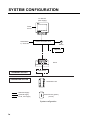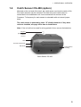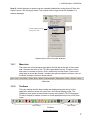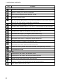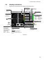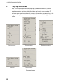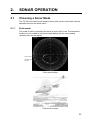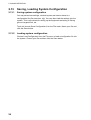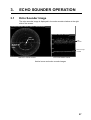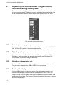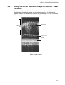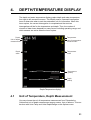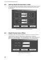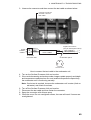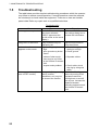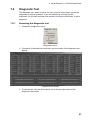
1
WIRED TRAWL SONAR
TS-331A
The paper used in this manual
is elemental chlorine free.
Your Local Agent/Dealer
9-52 Ashihara-cho,
Nishinomiya 662-8580, JAPAN
Telephone :
0798-65-2111
Fax
0798-65-4200
:
All rights reserved.
Printed in Japan
Pub. No. OME-13210
( DAMI ) TS-331A
FIRST EDITION : JAN
JAN.. 2005
*00015138400*
*00015138400*
*00015138400*
*OME13210A00*
*OME13210A00*
*OME13210A00*
SAFETY INSTRUCTIONS
WARNING
ELECTRICAL SHOCK HAZARD
Do not open the surface
processor unit.
Only qualified personnel should
work inside the equipment.
Do not disassemble or modify the
equipment.
WARNING
Do not place liquid-filled containers on
the top of the surface processor unit.
Fire or electrical shock can result if a liquid
spills into the unit.
Immediately turn off the power at the
switchboard if the surface processor
unit is emitting smoke or fire.
Fire, electrical shock or serious injury can
result.
Continued use can cause fatal damage to
the equipment. Contact a FURUNO
agent for service.
Immediately turn off the power at the
switchboard if water leaks into the
surface processor unit.
Make sure no rain or water splash leaks
into the surface processor unit.
Continued use of the equipment can cause
fire or electrical shock. Contact a FURUNO
agent for service.
Install batteries in the catch sensor with
correct polarity.
Improper polarity or size may cause the
batteries to explode.
Fire or electrical shock can result if water
leaks in the unit.
Use the proper fuse.
Use of a wrong fuse can result in damage
to the equipment or cause fire.
Use the proper battery in the surface
processor unit.
The mother board in the surface processor
unit has a battery which stores settings
when the power is off. Use the correct
battery and install it properly to prevent
explosion of the battery.
Warning Label
A warning label is attached to the surface
processor unit. Do not remove the label.
If the label is missing or damaged,
contact a FURUNO agent or dealer about
replacement.
WARNING
To avoid electrical shock, do not
remove cover. No user-serviceable
parts inside.
Name: Warning Label (1)
Type: 86-003-1011-1
Code No.: 100-236-231
i
TABLE OF CONTENTS
FOREWORD ........................................... iii
SYSTEM CONFIGURATION ................... iv
OPERATIONAL INFORMATION .............. v
1. OPERATIONAL OVERVIEW.................1
1.1 Surface Processor Unit........................... 1
1.2 Underwater Unit...................................... 2
1.2.1 Components of the underwater
unit ........................................... 2
1.2.2 Trawl system ............................ 2
1.2.3 Mounting the underwater unit
on the trawl............................... 3
1.3 Starting Up, Shutting Down..................... 4
1.3.1 Starting up................................ 4
1.3.2 Shutting down .......................... 4
1.4 Catch Sensor CS-400 (option)................ 5
1.5 Screen Layout......................................... 6
1.5.1 Menu bar.................................. 7
1.5.2 Toolbars ................................... 7
1.6 Display Indications.................................. 9
1.7 Pop-up Windows................................... 10
2. SONAR OPERATION ......................... 11
2.1 Choosing a Sonar Mode ........................11
2.1.1 Polar mode ............................ 11
2.1.2 Sector mode........................... 12
2.1.3 Locked mode ......................... 13
2.2 Adjusting the Sonar Image from the
Vertical Sonar Settings Dialog Box ........ 14
2.2.1 Choosing the display range .... 14
2.2.2 Adjusting gain ........................ 15
2.2.3 Choosing train angle .............. 15
2.2.4 Choosing scan sector............. 15
2.2.5 Choosing scanning speed ...... 15
2.2.6 Choosing sonar frequency...... 15
2.2.7 Freezing the display ............... 15
2.2.8 Reversing the scan direction .. 15
2.3 Monitoring Trawl Position...................... 16
2.4 Drawing Lines and Symbols ................. 18
2.4.1 Drawing a symbol................... 18
2.4.2 Drawing a line ........................ 18
2.4.3 Choosing line/symbol color..... 19
2.4.4 Clearing line/symbol art .......... 19
2.5 Finding Range and Bearing from Own
Ship to a Point........................................ 20
2.6 Zoom..................................................... 20
2.7 Choosing Display Color ........................ 21
2.8 Grid ....................................................... 22
2.9 Unit of Depth, Range Measurement ..... 23
2.10 Noise Filter............................................ 23
2.11 Recording Sonar Data .......................... 24
2.12 Playing Back Sonar Data...................... 24
ii
2.13 Saving, Loading System Configuration. 26
2.13.1 Saving system configuration... 26
2.13.2 Loading system configuration . 26
3. ECHO SOUNDER OPERATION ......... 27
3.1 Echo Sounder Image ............................ 27
3.2 Adjusting the Echo Sounder Image
from the Sounder Settings Dialog Box... 28
3.2.1 Choosing the display range .... 28
3.2.2 Adjusting data gain................. 28
3.2.3 Adjusting echo sounder gain .. 28
3.2.4 Freezing the display ............... 28
3.3 Using the Echo Sounder Image to
Monitor Trawl Location ........................... 29
3.4 Drawing Lines and Symbols.................. 30
3.5 Grid........................................................ 30
3.6 Zoom ..................................................... 30
3.7 Colors .................................................... 30
4. DEPTH/TEMPERATURE DISPLAY .... 31
4.1 Unit of Temperature, Depth
Measurement.......................................... 31
4.2 Setting Depth/Temperature Limits......... 32
4.3 Depth/Temperature Offset..................... 32
4.4 Depth/Temperature Scale Text Size...... 33
5. MENU DESCRIPTION ........................ 35
5.1
5.2
5.3
5.4
5.5
5.6
File Menu............................................... 35
View Menu............................................. 36
Communication Menu ........................... 37
Sonar Menu........................................... 37
Options Menu ........................................ 38
Help Menu ............................................. 39
6. CATCH SENSOR OPERATION.......... 41
6.1
6.2
6.3
6.4
6.5
6.6
Catch Sensor Dialog Box...................... 41
Catch Sensor Window........................... 42
Testing for Switch Activation.................. 43
Flashing LED Sequence ....................... 43
Catch Sensor Transmission Frequency 43
Installing the Batteries and O-ring......... 44
7. MAINTENANCE &
TROUBLESHOOTING ........................... 47
7.1
7.2
7.3
7.4
7.5
7.6
General Maintenance............................ 47
Replacement of Fuse ............................ 47
Replacement of Internal Battery............ 48
Testing the Underwater Unit.................. 48
Troubleshooting..................................... 50
Diagnostic Test...................................... 51
7.6.1 Executing the diagnostic test .. 51
7.6.2 Diagnostic test description...... 52
MENU TREE .......................................... 53
SPECIFICATIONS.............................. SP-1
INDEX ..................................................IN-1
FOREWORD
Introduction
FURUNO Electric Company thanks you for
considering and purchasing the TS-331A
Wired Trawl Sonar. We are confident you
will discover why the FURUNO name has
become synonymous with quality and
reliability.
The TS-331A is a wired trawl monitoring
system designed to improve control and
efficiency in pelagic and semi-bottom
trawling. Mainly consisting of an
Underwater Unit, a Surface Processor Unit
and a Mouse, the TS-331A presents data
received from a trawl-mounted transducer
on high quality and low-noise images.
No machine can perform to the utmost of its
ability unless properly installed, maintained
and operated. Please read and follow the
recommended procedures for operation
and maintenance to get the most out of the
equipment.
Features
The TS-331A is a third wire, head rope
mounted system incorporating a high
resolution scanning sonar designed
especially for monitoring the opening of the
trawl net and surrounding areas. Also
included are depth and temperature
sensors, a 120kHz downward looking echo
sounder, four catch indicators, and a pitch
and roll indicator for monitoring the attitude
of the trawl unit. The trawl unit is connected
to the Surface Processor Unit by a
2-conductor cable. This cable provides 130
VDC power to the trawl unit as well as
two-way communications.
Some of the main features are
• High resolution net profile
• Graphic presentation of net attitude
• Three display modes: polar (0°-360°),
locked (echo sounder) and sector (0°180°)
• Four catch sensors (option) may be
mounted on the codend to monitor catch.
Notice
• No part of this manual may be copied or
reproduced without written permission.
• If this manual is lost or worn, contact your
dealer about replacement.
• The contents of this manual and
equipment specifications are subject to
change without notice.
• The example screens (or illustrations)
shown in this manual may not match the
screens you see on your display. The
screen you see depends on your system
configuration and equipment settings.
• This manual is intended for use by native
speakers of English.
• FURUNO will assume no responsibility
for the damage caused by improper use
or modification of the equipment or
claims of loss of profit by a third party.
iii
SYSTEM CONFIGURATION
PC Monitor
(User supply)
Power
source
100-240VAC
1φ, 50-60 Hz
Surface Processor Unit
Mouse
Keyboard
Winch
Cable Block
SHIPBOARD SECTION
UNDERWATER SECTION
Underwater Unit
: Standard supply
: Optional supply
: Local, user supply
Catch Sensor (option)
(4 max.)
System configuration
iv
OPERATIONAL INFORMATION
The following may occur during operation. Follow the recommended procedure to restore
normal operation.
Cannot restore unit of temperature measurement to Celsius
Remedy
1. Choose Load Configuration from the File menu.
2. Find the file Default.cfg in the Imagenex program files and click Open.
If Fahrenheit is selected and Save Configuration is executed, the file Default.cfg will be
overwritten, which will prevent changing of unit of temperature measurement. If this occurs,
contact your dealer.
“Application error” results when the range is changed in the Settings
Dialog box after clicking the Pitch/Roll window
Remedy
1. Click “Don’t send” in the error message box at the bottom of the screen.
2. The application is quitted; click the TS331A icon to start up the application.
To change a sonar or echo sounder setting after application error occurs, first click the
corresponding window or run the corresponding diagnostic, and then change the setting.
“Application error” results when Total Length of Cod-End in the Catch
Sensor Setup dialog box is set to zero (0)
Remedy
1. Click “Don’t send” in the error message box at the bottom of the screen.
2. The application is quitted; click the TS331A icon to start up the application.
Set the Total Length of Cod-End to a value larger than 1 to prevent application error.
v
This page intentionally left blank.
vi
1.
OPERATIONAL OVERVIEW
1.1
Surface Processor Unit
The Surface Processor Unit (sometimes referred to as “Processor”) has a built-in
PC mother board, Windows XP®* operating system, and a hard drive with at
least 2GB disk space. The system provides a control and display application
TS331A.exe (installed on the Processor), which is a very convenient tool for
users to control system parameters such as acoustic operating range, scan
speed, scan area, etc. It also displays real-time data such as depth/temperature,
vertical sonar images, echo sounder images, pitch and roll, and catch sensor
information on the screen in resizable windows.
The mouse connects at the rear of the Processor and functions to control the
system, from various menus. Note that the system can also be controlled from a
keyboard (local supply).
POWER
Switch
Windows Startup
Switch
Surface processor unit
*: Windows XP is a registered trademark of Microsoft, Inc.
1
1. OPERATIONAL OVERVIEW
1.2
Underwater Unit
1.2.1
Components of the underwater unit
The underwater unit mainly consists of a red polyurethane case and three
transducers. The vertical sonar transducer is the cylindrical red housing which
extends from the back of the case. The (gray) echo sounder transducer is
mounted near the front of the unit. The catch sensor receiver transducer is
located at the back of the unit, to the right of the vertical sonar transducer.
Vertical Sonar Transducer
Pressure
Sensor
Third Wire
Cable
Echo Sounder
Transducer
Underwater unit, cover removed
1.2.2
Catch
Sensor
(option)
Trawl system
Underwater
Unit
Third Wire
Cable
Trawl system
2
Catch Sensor
Receiver Transducer
1. OPERATIONAL OVERVIEW
1.2.3
Mounting the underwater unit on the trawl
Usually the underwater unit is fixed either on the head rope of the trawl or on the
belly just above the ground rope.
The advantage of the former position is that the underwater unit is held
horizontal almost throughout the towing operation and consequently a good,
stable image can be expected. Its disadvantage is that it is difficult to detect the
ground rope, especially in bottom trawling since the ground rope in the bottom
trawl becomes positioned farther back than the head rope. In mid-water and
pelagic trawls, the ground rope usually becomes positioned below the head rope
and hence the ground rope is easily detected with the underwater unit on the
head rope.
The underwater unit is typically enclosed in a “pouch” made of fine mesh netting
and attached to the head rope with ropes. The pouch is attached to a small
mesh net (smaller trawlers) with ropes to stabilize the underwater unit. (Smaller
trawlers may not require the small mesh net for stabilization.) The small mesh
net is attached to the trawl with ropes.
Small mesh net for
stabilizing underwater
unit
Underwater
Unit
"Pouch" made of
fine mesh netting
Head Rope
Small mesh net
Underwater
Unit
Head Rope
Pouch for
underwater
unit
Typical installation of underwater unit (for larger trawler)
3
1. OPERATIONAL OVERVIEW
1.3
Starting Up, Shutting Down
1.3.1
Starting up
1.
2.
3.
4.
Check the connection between the underwater unit and the winch.
Mount the underwater unit on the trawl, referring to paragraph 1.2.3.
Shoot the trawl.
Turn on the processor unit and the monitor. Adjust display brilliance referring
to the owner’s manual of the monitor.
5. Push the Windows Startup switch on the Processor to start up Windows®.
The system will start up loading the Windows® XP* operating system and
then the TS331A program.
You can exit this application by clicking the “close window” button (X) at the
upper right corner of the screen or use the menu command File->Exit.
When the power is turned on, the normal screen display should appear. Then,
the sonar head calibrates itself by moving its transducer to the center or zero
angle and waits for the “scan command” from the Processor. The head then
scans based on the last-used settings of MODE, SECTOR, TRAIN and SPEED.
If the message “No Communication” appears, check connections.
1.3.2
Shutting down
1. Since the Processor is running a Windows®* operating system, before you
turn off the Processor, shut down the computer first. Click Start->Turn Off
Computer->Shut Down. Wait a few seconds until the system shuts down.
Then, turn off the power of the Processor.
2. Turn off the monitor.
3. Haul the net.
*: Windows and Windows XP are registered trademarks of Microsoft, Inc.
4
1. OPERATIONAL OVERVIEW
1.4
Catch Sensor CS-400 (option)
Mounted on the cod end of the trawl, the catch sensor monitors the catch of fish.
Four catch sensors may be mounted. The data from each catch sensor is
transmitted to the underwater unit via the acoustical link and sent to the
Processor. Tx frequency for each sensor is selectable with an internal jumper
block.
The catch sensor is powered by three “D” alkaline batteries. If they have
not been installed, see page 44 for how to install them.
Note: If the unit will not be used for a long period of time, remove the batteries.
Lanyard
(Secured to
codend
of net.)
LED
Acoustic transducer
Electrode
Polyurethane
Housing
Catch Sensor CS-400
5
1. OPERATIONAL OVERVIEW
1.5
Screen Layout
The fully configured TS-331A provides five viewing windows (Vertical sonar
image, Depth/water temperature information, Echo sounder image, Catch sensor
information, and Pitch/roll information) plus a Settings dialog box*.
* The Vertical Sonar Settings dialog box is initially shown.
8
1
2
File
View
Color Table
Grids
Draw
Mode
Communication
Diagnostics
Sonar settings: Range: 30 M, Gain: 70%, Speed: 03',
Sonar
Options
Help
Mode: Sector, Freq: High
*
3
*Vertical
2
1
1
7
6
3
3
2
1
1
6
6
1
1
2
3
6
1
Echo Sounder: Range: 50 M,
Gain:10 dB
*
1
2
6M/DIV
3
Depth
Bottom:
Trawl:
CodEnd:
4
DateTime 24-SEP-04 1:23:01
Trawl
Pitch: +0.0
Roll : +0.0
Cod End
Pitch:---Roll :----
Ship's Course :
Ship's Speed :
Trawl Direction:
Tr. Water spd :
CE Water spd :
5
1 Menu bar
2 Toolbar
6
* Items available depend on active window.
Items not available appear in gray.
3 Vertical sonar image
4 Pitch/roll information
5 Catch sensor information
6 Echo sounder image
7 Settings dialog box*
8 Depth/water temperature information
Screen layout
Note 1: You can drag a window’s border to resize the window to your desired size or drag
the window’s title bar to move the entire window.
6
1. OPERATIONAL OVERVIEW
Note 2: Certain devices or sensors can be manually disabled by turning them off from the
Options menu. See the figure below. The vertical sonar image cannot be disabled; it is
always displayed.
These displays can be
turned on or off.
Options menu, Echo Sounder selected
1.5.1
Menu bar
The menu bar is the horizontal strip below the title bar at the top of the screen
and it contains the titles of the TS-331A’s drop-down menus. To open a menu,
sub menu or choose an option, click it with the left mouse button. A sub menu
which has an arrow (►) means it contains an options selection window, such as
the Echo Sounder sub menu shown above.
File
View
Color Table
Grids Draw
Mode
Communication
Diagnostics
Sonar
Options
Help
Menu bar
1.5.2
Toolbars
The main toolbar and the draw toolbar are displayed across the top of the
application window, below the menu bar in the normal display mode. The
toolbars provide quick mouse access to many tools used in TS-331A program.
To hide or display a toolbar, uncheck or check appropriate tool bar on the View
menu.
Main toolbar
Draw toolbar
Toolbars
Toolbar description
7
1. OPERATIONAL OVERVIEW
Tool
Function
Main Toolbar
Connects to sonar head.
Opens an existing .331 data file to play back.
Saves real-time acquired sonar data to a .331 file.
Stop saving real-time data.
Increases operating range by one level. Vertical sonar range: 10, 20, 30, 40, 50, 60,
80, 100, 150, 200, 250 (meters) or equivalent feet/fathoms. Echo sounder range: 50,
100, 150, 200, 300 (meters) or equivalent feet/fathoms.
Decreases operating range by one level.
Increases data (display) gain by 1 per cent for vertical sonar and echo sounder.
Decreases data (display) gain by 1 per cent for vertical sonar and echo sounder.
Increases train angle by 10 degrees (vertical sonar only).
Decreases train angle by 10 degrees (vertical sonar only).
Increases sector size by 10 degrees (vertical sonar only).
Decreases sector size by 10 degrees (vertical sonar only).
Increases sonar scan speed (vertical sonar only).
Decreases sonar scan speed (vertical sonar only).
Clears the screen (vertical sonar, echo sounder, and depth/temp windows).
Context sensitive help.
Draw Toolbar
Draws a line on the screen, with distance shown.
Draws a line on the screen, with range and bearing shown.
Deletes all lines and symbols drawn on the screen.
+
Draws a “+” symbol on the screen at the current mouse position.
Stops drawing objects on the screen.
8
1. OPERATIONAL OVERVIEW
1.6
Display Indications
Below are all the indications which appear on the display screen.
Sonar settings
Range, gain,
speed, mode,
frequency
Asterisk(blinking)
Blinks when depth/water
temp. data is received.
Depth Temp.
scale scale
Color
indicator
File
View
Color Table
Grids
Draw
Mode
Communication
Diagnostics
Sonar settings: Range: 30 M, Gain: 70%, Speed: 03',
Sonar
Options
Settings dialog box
Item not available with
active window is shown
in gray.
Help
Mode: Sector, Freq: High
*
3
Asterisk(blinking)
*Vertical
Green: Receiving
signal from underwater unit
Red: No signal
2
Active window indicator
Color changes according
to active window.
Med. blue : Sonar
Green
: Depth/temp
Red
: Echo sounder
Light blue : Catch sensor
Purple
: Pitch/roll
Grid
1
1
6
Grid
(Circular or
Scale
square)
3
FURUNO logo
appears here.
2
1
1
6
6
1
1
2
3
6
1
Echo Sounder: Range: 50 M,
*
1
Depth
Bottom
Trawl
Cod End
Date, Time
Catch sensor indicator
Time figure is how long
since sensor has
been activated.
Color inside each
section changes with
catch sensor status.
Triggered: Red
Standby: Yellow
Sleep:
Bkgd color
2
6M/DIV
Depth
Echo sounder settings
Range, gain
2
Grid
3
Bottom:
Trawl:
CodEnd:
DateTime 24-SEP-04 1:23:01
Gain:10 dB
Trawl
Pitch: +0.0
Roll : +0.0
Cod End
Pitch:---Roll :----
*1
Ship's Course :
Ship's Speed :
Trawl Direction:
Tr. Water spd :
CE Water spd :
*1 Pitch and Roll Indicator
Analog and digital indications
of net attitude at trawl and
cod end.
*2 Nav data
Course, speed, trawl direction,
trawl water speed, cod end
water speed. Requires appropriate
sensors.
*2
Color
indicator
Scale
Asterisk(blinking)
Green: Receiving signal
from echo sounder
Red: No signal
Indications
9
1. OPERATIONAL OVERVIEW
1.7
Pop-up Windows
The TS-331A provides convenient pop-up windows from which to conduct
various operations for the vertical sonar window, echo sounder window,
depth/temperature window, pitch/roll window and catch sensor window. To
activate a pop-up window, place the cursor in the window corresponding to the
pop-up menu you want to use and then click the screen with the right mouse
button.
Vertical sonar
Echo sounder
Pitch/roll
Catch sensor
Pop-up windows
10
Depth/temperature
2.
SONAR OPERATION
2.1
Choosing a Sonar Mode
The TS-331A has three sonar display modes: polar, sector and locked. Choose
desired mode from the Mode menu.
2.1.1
Polar mode
This mode is used for operating the sonar to scan a 360° area. The transducer
location is in the middle of the sonar image display with the zero heading
vertically down on the display.
Fish in trawl
Ground rope
of trawl
Polar mode display
Polar mode concept
11
2. SONAR OPERATION
2.1.2
Sector mode
This mode is used for operating the sonar to scan in a sector area. The
transducer location is in the middle of the sonar image display with the zero
heading vertically down on the display. The user can adjust the scan sector size
by selecting the desired sector size from the Sector combo box in the Vertical
Sonar settings dialog box. Sector size can be from 0° to 360° in 10° increments.
The user can move the mid-point of the sector to any angle in 10° increments by
selecting the desired train angle from the Train combo box in the vertical sonar
settings dialog box. The user can use the Zoom Factor command in the View
menu to enlarge or shrink sonar images and the mouse can be dragged to
position the image where desired.
Fish in trawl
Ground rope
of trawl
Sector mode display
Sector mode concept
12
2. SONAR OPERATION
2.1.3
Locked mode
This mode functions to operate the sonar as an echo sounder, with the
transducer locked at 0° sector size. The transducer location is at the top of the
sonar image display and the image data is displayed across the screen from
right to left.
Individual fish
(angular echoes)
in trawl
Ground rope of trawl
Bottom
Locked mode display
13
2. SONAR OPERATION
2.2
Adjusting the Sonar Image from the Vertical
Sonar Settings Dialog Box
The vertical sonar settings dialog box contains all the controls for adjustment of
the sonar image. To display this box if it is not displayed, click the sonar image
with the left mouse button and then choose Show Sonar Settings from the View
menu.
Vertical sonar settings dialog box
2.2.1
Choosing the display range
The Range combo box lets you choose desired display range, from the ranges
shown in the table below.
Ranges
14
Meters
Feet
Fathoms
250
750
125
200
600
100
150
450
75
100
300
50
80
240
40
60
180
30
50
150
25
40
120
20
30
90
15
20
60
10
10
30
5
2. SONAR OPERATION
2.2.2
Adjusting gain
Adjust the gain from the Data Gain combo box. The gain range is 0-100(%).
Data gain is used to increase or decrease the intensity (color levels) of the
vertical sonar and sounder images.
2.2.3
Choosing train angle
Select the scan train angle from 0° to 360° in 10° increments. Train angle is used
to control the relative direction of the mid point of the vertical sonar in the sector
scan mode. Train is inoperative in the polar mode.
2.2.4
Choosing scan sector
Select the scan sector (from 0° to 360° in 10° increments). Sector is used to
control the size of the angle scanned by the vertical sonar. Note that this function
is inoperative in the polar and locked modes.
2.2.5
Choosing scanning speed
Select scan speed of vertical sonar. The options are
0.3 deg.: slow, one shot covers 0.3°
0.6 deg.: medium, one shot covers 0.6°
0.9 deg.: fast, one shot covers 0.9°
1.2 deg.: faster, one shot covers 1.2°
2.4 deg.: fastest, one shot covers 2.4°
2.2.6
Choosing sonar frequency
Choose the vertical sonar operating frequency for high or low.
2.2.7
Freezing the display
Click the HOLD button to freeze the system from interrogating sensors and
freeze the data display. The sonar display shows “HELD” when the image is
frozen. Click the button once again to release the freeze condition and restart
the sonar. This feature is useful for inspecting an image, taking a picture of the
display and printing.
2.2.8
Reversing the scan direction
Click the REV button to reverse the current scan direction of the vertical sonar. If
the sonar is scanning clockwise, clicking the REV button will make the sonar
scan counter clockwise and vice-versa. This is particularly useful when tracking
moving targets.
15
2. SONAR OPERATION
2.3
Monitoring Trawl Position
The Locked mode can be a valuable tool for monitoring trawl location in order to
prevent damage to the trawl by shoal or other protrusion.
Ground rope
If the ground rope is positioned in the coverage area of the sounding beam it is
displayed as a line almost parallel with the transmission line. If a fish school
appears between the transmission line and the ground rope it can be considered
to be entering the trawl.
The interval between the transmission line and the ground rope is equivalent to
the height of the trawl opening and therefore the interval is kept constant if the
trawl is being properly towed. If it is unsteady, or if the ground rope rises
suddenly, towards the transmission line, the trawl may be caught on some
object.
Image and fishing operations
The illustration and descriptions below show the relation between trawl and the
LOCKED mode image in bottom trawling.
Display range changed
Ground Rope
1
2
3
4
5
6
7
8
9
10 11
Example fishing operation and echo sounder image
1. The trawl is set into water and begins descending. In the image, the distance
between the transducer and the bottom gets shorter and shorter as if the
bottom is rising toward the transmitter unit. On the other hand, the distance
between the transducer and the sea surface increases as if the sea surface
is receding from the transducer. The range has been changed twice for
shorter ranges.
2. The trawl has settled on the bottom.
3. The trawl is being towed along the bottom. Fish entering the trawl are seen
above the ground rope. The ground rope is being kept at a constant distance
from the transducer, indicating that the trawl mouth is opening properly in the
course of towing.
16
2. SONAR OPERATION
4. The ship has accelerated to clear a shoal. The trawl is rising off the bottom
and the bottom is displayed as if it has a sharp undulation though it actually
does not.
5. The trawl is passing over the shoal. The ground rope seen off the bottom
indicates that the shoal has been cleared.
6. The trawl has settled on the bottom again.
7. The trawl is being towed along the bottom.
8. Hauling of the trawl has begun.
9, 10.As the hauling proceeds, the bottom echoes are becoming distant and the
sea surface echoes are getting nearer to the transmission line.
11. Hauling is completed.
17
2. SONAR OPERATION
2.4
Drawing Lines and Symbols
Using the draw tool bar or the Draw menu, you can draw lines and symbols on
the sonar display (to mark important echoes). This can be done from the Draw
menu or with the Draw toolbar.
2.4.1
Drawing a symbol
Choose Symbol from the Draw menu or click the + button on the draw toolbar.
Roll the mouse to position the cursor in the sonar display and click the left
mouse button. The symbol (“+”) is placed at the cursor intersection. Repeat the
above procedure to draw another symbol.
Symbol
Cursor
Appearance of symbol on the display
2.4.2
Drawing a line
Choose Line from the Draw menu or click the
button on the draw toolbar.
Roll the mouse to position the cursor on the starting point and click the left
mouse button. Roll the mouse again to position the cursor on the end point and
click the left mouse button. The distance between the points is shown at the end
point. Repeat the above procedure to draw another line.
Drag cursor here.
D:223.9M
Cursor
Starting
point
Drawing a line on the display
18
Distance between
starting point and
end point
2. SONAR OPERATION
2.4.3
Choosing line/symbol color
The default line/symbol color is white. However, you may choose line/symbol
color as desired. Choose Line/Symbol Color from the Draw menu, and the dialog
box shown below appears. Choose the desired color and then click the OK
button.
Color dialog box
2.4.4
Clearing line/symbol art
Clearing all symbols
Place the cursor on a symbol and then double-click the left mouse button.
Clearing a line
Place the cursor on the ending point of the line you wish to erase and then
double-click the left mouse button.
Clearing all symbol/line art
Choose Clear line Art from the Draw menu.
Stopping drawing
The Stop Drawing command in the Draw menu is used to quit any drawings.
19
2. SONAR OPERATION
2.5
Finding Range and Bearing from Own Ship to a
Point
Choose Range / Bearing from the Draw menu or click the
button on the
draw toolbar. Roll the mouse to position the cursor where you want to measure
the range and bearing and click the left mouse button. The range and bearing
from own ship to the point is shown. To find the range and bearing between to
other points, repeat the above procedure.
Range and bearing
to point
+
R: 199.5m
B: 348.1 Deg
Finding range and bearing from own ship to a point
2.6
Zoom
Zoom Factor on the View menu lets you choose the zoom magnification, from
100, 125, 150, 175, 200, 300 and 400 (%).
20
2. SONAR OPERATION
2.7
Choosing Display Color
You may choose the color arrangement for the vertical sonar image. Open the
Color Table menu and check color desired.
Color Table menu
Color table menu description
Normal High:
This scale maps echo data amplitude to 118 colors, ranging
from black (low strength) through blue, green, orange, yellow,
white and red (highest strength).
Normal Low:
Same colors as Normal High but a lower color intensity
Green:
118 shades of green.
Grey:
118 shades of grey (white on black).
Reverse Grey:
118 shades of grey (black on white).
Brown/Yellow:
118 mixed shades of brown and yellow.
Green/Blue:
118 mixed shades of green and blue.
Green/Yellow:
118 mixed shades of green and yellow.
Blue:
118 shades of blue.
21
2. SONAR OPERATION
2.8
Grid
You may configure the grid on the vertical sonar display as desired from the
Grids menu.
Grids menu, Scale Options, Scale Text Size selected
Grids menu description
Circular grid:
Square grid:
Check to display a circular grid.
Displays a square grid.
Circular grid
Square grid
Circular and square grids
No Grid:
Check to turn off grid.
Scale options: Turns scale on or off, turns shadow behind scale on or off, and
chooses text scale text size.
Enable Shadow: Check to enable shadowing behind scale.
Choose Shadow Color: Click to display color dialog box to
choose color of shadow.
Scale Text Size: Choose text size from small, medium, large,
larger and largest.
22
2. SONAR OPERATION
2.9
Unit of Depth, Range Measurement
The unit of depth/range measurement may be chosen from meters, feet and
fathoms, on the Options menu. Check the unit desired.
Options menu, Units, Depth/Range selected
2.10
Noise Filter
You may encounter occasional or intermittent noise and interference on the
vertical sonar display or echo sounder display. Noise is mostly caused by
electrical equipment engine or propeller noise from own ship or noise from other
sonars being operated nearby. To suppress this noise, check Noise Filter on the
Options menu. Uncheck it if no noise is present.
23
2. SONAR OPERATION
2.11
Recording Sonar Data
You may save real-time data to a file. To save real-time data, do the following:
1. Choose Record Sonar Data from the File menu. The Save as dialog box
appears.
2. Choose location where to save the file and enter file name.
3. Click the Save button to save the data.
The TS-331A automatically adds the extension “.331”. The equipment will
continue interrogating the sonar unit for data while at the same time recording
those data to a file.
To stop recording sonar data, choose Stop Data Recording from the File
menu.
2.12
Playing Back Sonar Data
You can also use the TS-331A.exe program to playback data that has been
recorded to a file (with file extension .331).
To open a .331 data file to playback, select “File->Open File to Playback” or click
. When the program is running in file playback mode, the
the Toolbar button
frame window will show a File Playback dialog bar. You can drag and dock it to a
convenient place on the screen. This dialog bar lets you control the playback
speed and playback file position.
File progress indicator, playback speed selector
File Progress: A slider bar with the pointer showing file playback position similar
to the slider bar on the property page. Dragging the pointer to a new position will
cause the file playback to start at that position. The slider range represents the
file size.
Since the playback speed is fast, sometimes it is difficult to catch the right
pointer position, because the pointer re-draws its position every time after a file
record is processed. It is better to set the file playback on hold before you drag
or click the slider bar.
Play Back Speed: Pressing the spin button up or down will change the playback
speed faster or slower. The speed change will show in the speed progress bar.
24
2. SONAR OPERATION
Once a sonar data file has been opened, the operation of real-time sonar data
acquisition will terminate. Although only one sonar data file may be opened at a
time, another data file may be opened, closing the current file.
You can once again change the operation to real time data interrogation by
selecting “menu->File->Connect to Sonar Head” or clicking the Toolbar button
. When the system begins acquiring data from the sonar head, the current
data file will be closed.
The TS-331A program provides several convenient methods (menu commands,
dialog boxes, and toolbar commands) to control the sonar unit’s operations,
operating parameters and data display windows.
25
2. SONAR OPERATION
2.13
Saving, Loading System Configuration
2.13.1
Saving system configuration
You may save sonar settings, window layouts and sensor status to a
configuration file (file extension .cfg). You may then load the settings into the
system. This is convenient for setting up the equipment according to fishing
ground, targeted fish, etc.
To do this choose Save Configuration from the File menu. Name your file and
click the Save button.
2.13.2
Loading system configuration
Choose Load Configuration from the File menu to load a configuration file into
the system. Choose your file and then click the Save button.
26
3.
ECHO SOUNDER OPERATION
3.1
Echo Sounder Image
The echo sounder image is displayed in the echo sounder window at the right
side of the screen.
Sonar settings:
Range: 30 M,
Gain: 70%,
Speed: 03',
Mode: Polar, Freq: High
Echo Sounder: Range: 50 M,
Gain:10 dB
Fish
in trawl
Fish
in trawl
Ground
rope of
trawl
Ground rope
of trawl
VERTICAL SONAR IMAGE
ECHO SOUNDER IMAGE
Vertical sonar and echo sounder images
27
3. ECHO SOUNDER OPERATION
3.2
Adjusting the Echo Sounder Image from the
Sounder Settings Dialog Box
The echo sounder settings dialog box contains all the controls for adjustment of
the echo sounder image. To display this box, click the echo sounder image with
the left mouse button and then choose Show Sonar Settings from the View
menu.
Echo sounder settings dialog box
3.2.1
Choosing the display range
The Range combo box lets you choose desired display range, from 50, 100, 150,
200, 250 and 300 (meters) or equivalent feet/fathoms.
3.2.2
Adjusting data gain
Adjust the gain from the Data Gain combo box. The gain range is 0-100(%).
Data gain is used to increase or decrease the intensity (color levels) of the
vertical sonar and sounder images, collectively.
3.2.3
Adjusting echo sounder gain
Choose the ES Gain combo to adjust the gain of the connected echo sounder.
The gain can be adjusted from 0dB to 20dB in 1 dB increments.
3.2.4
Freezing the display
Click the HOLD button to freeze the system from interrogating sensors and
freeze the data display. The echo sounder display shows “HELD” when the
image is frozen. Click the button once again to release the freeze condition and
restart the echo sounder. This feature is useful for inspecting an image or taking
a picture of the display.
28
3. ECHO SOUNDER OPERATION
3.3
Using the Echo Sounder Image to Monitor Trawl
Location
If the ground rope is positioned in the coverage area of the sounding beam it is
displayed as a line almost parallel with the transmission line. If a fish school
appears between the transmission line and the ground rope it can be considered
to be entering the trawl.
Transmission line
Height of
Trawl
Opening
Fish School
Ground rope
of trawl
Bottom
Echo sounder display
29
3. ECHO SOUNDER OPERATION
3.4
Drawing Lines and Symbols
The procedure for drawing lines and symbols on the echo sounder is similar to
that for the sonar display. For details, see paragraph 2.4.
3.5
Grid
You may display a line grid on the echo sounder display. Check Line Grid on the
Grids menu to display the grid.
10 M
20 M
30 M
40 M
50 M
Line grid
3.6
Zoom
Zoom Factor on the View menu lets you choose the zoom magnification, from
100, 125, 150, 175, 200, 300, and 400 (%).
3.7
Colors
You may choose the color arrangement for the echo sounder. Open the Color
Table menu and check color desired. For details, see page 21.
30
4.
DEPTH/TEMPERATURE DISPLAY
The depth and water temperature display graphs depth and water temperature,
from right to left across the screen. This display uses a 3-second interrogation
timer to determine when to ask the underwater unit for information. When this
timer expires, the current interrogation is completed and the next two
interrogations will be for the temperature and depth. Thus, the number of
minutes of data shown depends on many factors including operating range, and
which sensors are active when the timer expires.
Depth
Unit of depth
measurement
*
Temperature
Unit of temperature
measurement
Depth
scale
Temperature
scale
Temperature
(yellow)
Depth
(white)
Depth/Temperature display
4.1
Unit of Temperature, Depth Measurement
You may choose the unit of temperature measurement from Fahrenheit or
Celsius and unit of depth measurement among meters, feet or fathoms. This can
be done with Units-Temp and Units-Depth/Range on the Options menu.
31
4. DEPTH/TEMPERATURE DISPLAY
4.2
Setting Depth/Temperature Limits
You may set the depth and temperature display limits with Depth/Temp Limits on
the Options menu. Set low and high limits with the spin buttons and then click
the OK button.
Set Depth/Temperature Scales dialog box
4.3
Depth/Temperature Offset
If the depth and/or temperature readout is incorrect you may enter an offset to
correct it(them). Choose DT Offset from the Options menu to show the
Depth/Temp Offset dialog box. Enter the appropriate offset with the spin buttons
and then press the OK button. To remove the offsets, click the Reset button.
Depth/Temp Offset dialog box
32
4. DEPTH/TEMPERATURE DISPLAY
4.4
Depth/Temperature Scale Text Size
You may choose the size of the depth/temperature scale text with DT Scale Text
on the Options menu.
Options menu, DT Scale Text selected
33
4. DEPTH/TEMPERATURE DISPLAY
This page intentionally left blank.
34
5.
MENU DESCRIPTION
This chapter provides menu information not discussed in previous chapters.
5.1
File Menu
Connect to Sonar
head
Use this command to communicate with the TS331A underwater unit.
The control software begins to interrogate the sonar unit for data in
real-time through an RS-232 connection. The system uses COM2 as
the default serial port for communications between the analog interface
board and surface control system.
Print
Prints an image of the currently selected window.
Print Preview
Displays the currently selected window on the screen, as it would
appear printed.
Print Setup
Selects a printer and printer connection.
Exit
Use this command to terminate your TS-331A program. System will
save your display layout, sonar settings and sensor enable/disable
status to default.cfg file. The next time you start the program, the
system will load these default settings.
35
5. MENU DESCRIPTION
5.2
View Menu
Clear Screen
Use this command to clear the image in one of vertical sonar, echo
sounder and DT (Depth/Temperature display windows. Which window
contents will be cleared depends on which window is active. To activate
a window (set it on focus), click on that window.
Full Screen
Use this command to toggle full-screen and normal display mode. Full
screen display mode hides the main menu, main toolbar, draw toolbar,
and title bar to make more room for display windows.
Since full screen mode hides command menus and toolbars, if you need
to issue a command, you can use the context popup menu, which has
the same commands as in the main menu. Right clicking the mouse
button in any window will display the context popup menu.
You can use menu->view->main menu (in context popup menu) to show
the main menu and use menu->view->main toolbar to show the main
toolbar.
Restore Image
Use this command to restore the vertical sonar or echo sounder image.
When you move the image by clicking and dragging (or zooming) the
image, the image may not be seen in the viewing window. Use this
command to restore the image to its original size and position.
Color Indicator
Use this command to display and hide the color table indicator bar,
which displays the color table used to represent echo strength. If
enabled, this color table bar is displayed on the right side of the vertical
sonar and echo sounder windows. The upper level colors represent
higher echo strength, and lower level colors represent lower echo
strength. A check mark appears next to the menu item when color table
indicator bar is displayed.
Use the menu command Color Table to choose your preferred colors to
display the sonar image.
Scan Direction
36
Use this command to display and hide the scan direction line on the
vertical sonar window. This dotted yellow line represents the vertical
sonar shooting direction. A check mark appears next to the menu item
when scan direction line is displayed.
5. MENU DESCRIPTION
5.3
Communication Menu
Choose Sonar Com
Port
Choose another serial communication port for sonar data acquisition.
Choose desired port from the combo box and click the OK button.
GPS Data-In
No use.
Data-Out
No use.
5.4
Sonar Menu
BowScan
Sets TS-331A.exe to Bowscan mode. All sensors are disabled except
vertical sonar.
TS-331A
Sets TS-331A.exe to TS-331A mode. All sensors are functional.
37
5. MENU DESCRIPTION
5.5
Options Menu
Color Threshold
The Color Threshold dialog box allows the user to adjust the
color table for the echo sounder and vertical sonar windows
individually. Note that the sonar return data is not
compromised and is recorded to file independent of the
color thresholding. Thus on file playback, the threshold may
be altered according to need.
Detection Threshold: This adjusts the point at which data
is displayed. All sonar data values below the detection
threshold show as black.
Saturation Threshold: This adjusts the point at which data
is displayed as red. All sonar data values above the
saturation threshold show as red.
Data Value < Detection Threshold = Display as Black
Detection Threshold < Data Value < Saturation Threshold
Datavalue *107
Datavalue = --------------------Saturation Threshold
Data Value > Saturation Threshold = Display as Red
Roll Correction
Roll Angle Display->ON
Roll Angle Display->OFF
Echo Sounder Beamforming
Continuous Rotation
1, 2, 3, 4
38
Enable/disable roll correction. If enabled, vertical sonar
image display will compensate the roll offset.
Display a dashed line indicating the roll angle relative to the
vertical sonar image.
Hide the dashed line indicating the roll angle.
Apply a beam-forming technique to the echo sounder
display.
The vertical sonar can scan continuously in one direction
(clockwise or counter clockwise).
Choose active window/dialog box. 1, Vertical sonar window;
2, Settings dialog box; 3, Echo sounder window, 4, Catch
sensor window.
5. MENU DESCRIPTION
5.6
Help Menu
The Help menu offers the following commands, which provide you assistance with this
application:
Help Topics
Help Contents
Provides a list of help topics.
Offers you a list of contents on which you can get help.
Use this command to display the opening screen of Help. From
the opening screen, you can jump to step-by-step instructions for
using TS-331A and various types of reference information.
About
Use this command to display the copyright notice and version
number of your copy of TS-331A as well as contact information.
39
5. MENU DESCRIPTION
This page intentionally left blank.
40
6.
CATCH SENSOR OPERATION
6.1
Catch Sensor Dialog Box
The Catch Sensor Setup dialog box provides a tool for you to configure the
catch sensors on a trawl net. You can install up to four catch sensors on the
TS-331A system. TS-331A program default settings display four catch sensors.
You can click the Delete button in this dialog box to remove catch
sensor/sensors if less than 4 catch sensors are installed.
Catch sensor setup dialog box
The Catch Sensor Setup dialog box provides the following options:
Enable catch sensor (check boxes)
Checking/Unchecking the “Enable Catch Sensor” check box will enable/disable
that particular catch sensor. There can be a maximum of four catch sensors
installed at a time.
Catch Sensor ID (edit boxes)
The Catch Sensor ID is a number used to distinguish different catch sensors.
Each sensor transmits an acoustic signal with its own fixed frequencies so the
system knows which one is installed (received a standby signal) or triggered
(received a triggered signal). TS-331A uses number 1 to 4 to distinguish them.
1:
2:
3:
4:
69.75kHz/70.25kHz ±50Hz
72.25kHz/72.75kHz ±50Hz
74.75kHz/75.25kHz ±50Hz
77.25kHz/77.75kHz ±50Hz
It is not required to install the sensor number 1 at the first position (Pos1), sensor
number 2 at the Pos2, etc. You may install sensor number 1 at Pos4, for
example. In this case, you need to input the right numbers of the sensor ID at
the corresponding position.
41
6. CATCH SENSOR OPERATION
Catch Sensor relative position (edit boxes)
Input the relative length between two catch sensors in meters.
Total Length of Cod-End
Input the total length of the trawl net in meters.
Add (button)
Add another catch sensor (maximum of 4) in catch sensor display.
Delete (button)
Delete one sensor.
After changes are made and accepted, by clicking the “OK” button, the catch
sensor display will adjust to those changes.
6.2
Catch Sensor Window
The catch sensor window is located below the pitch/roll window and it indicates
catch sensor status and sensor activation time.
The program has an internal timer which counts sensor activation time. If the
trigger (indicated by showing red in a sensor status window) is present for two
minutes, the timer starts counting. This two-minute gap between trigger
presence and timer start is done to prevent false readings. After another minute
has passed, the indicator will show "00:01" and will update once every minute.
The timer continues to count even if the signal goes away (for example, the
catch sensor points in wrong direction). This is shown on the catch sensor
window by displaying a time, but no color (red or yellow) is seen in the catch
window. You may reset the timer by left-clicking Reset Catch Sensors in the
Options menu.
Catch sensor status
Color shows status.
Triggered: Red
Standby: Yellow
Sleep:
Bkgd color
00:00
00:00
Catch sensor window
42
Catch sensor
activation time
(hr:mm)
00:00
00:00
6. CATCH SENSOR OPERATION
6.3
Testing for Switch Activation
To test for proper switch activation, do the following:
1. Submerge the unit in SALT water or short the electrode and trigger bolt.
2. Wait for about 20 seconds, then pull the lanyard for a few seconds and let go.
The LED should flash 13 seconds after the lanyard was pulled. This is the catch
frequency. 13 seconds after the first flash it will flash again. This is the active
frequency.
6.4
Flashing LED Sequence
This paragraph describes the LED sequences for the catch sensor.
1. When the batteries are first installed in the unit, the LED will flash, after a
10-second delay, 15 times. This merely indicates that there is power to the
CPU and it is running.
2. When the unit is submerged (or the electrode and trigger bolt are shorted for
test purposes), the LED will flash four times. This means the unit is in water.
3. After a delay of two seconds, the LED will flash once for every 100 hours that
the unit has been in water without removing the batteries. If the unit has been
operated for under 100 hours it will not flash.
Note: If the battery cap is removed, the 100 hour counter will reset.
4. About 11 seconds after step 3 has been completed, the LED will flash once.
This is when the unit is actually transmitting. If the unit is kept in water, the
LED will flash every 90 seconds. (The flash indicates transmission.)
Step 4 only occurs the first time the unit is activated with new batteries. After the
first time, whenever the unit is activated (via a jumper or submerged) only steps
2 and 3 occur.
6.5
Catch Sensor Transmission Frequency
The transmission frequency of the catch sensor(s) can be changed, by a
qualified technician. For further details, contact a FURUNO agent or dealer.
43
6. CATCH SENSOR OPERATION
6.6
Installing the Batteries and O-ring
The catch sensor is powered by three “D” alkaline batteries and battery life is
about 1,000 hours. When the battery voltage is low, the appropriate (yellow)
“active indicator” on the catch status indicator does not appear. When this occurs,
replace the batteries. It is also recommended to replace the O-ring whenever the
batteries are replaced. Replacement of the O-ring is not necessary if batteries
are being installed for the first time.
Necessary tools and parts
•
•
•
•
•
Socket wrench w/19 mm or 3/4-inch socket head
Slotted-head screwdriver
Three “D” alkaline batteries (International Standard Number R20)
O-ring (Parts no. 834-625-024)
Silicone grease (non-zinc type)
1. Use the socket wrench and socket head to unfasten the nut fixing the trigger
bolt. Remove the trigger bolt together with the trigger magnet housing. Clean
the trigger bolt with freshwater.
Transducer end
Nut
Trigger Bolt
Battery Cap
end
Polyurethane
Housing
Trigger Magnet
Housing
TRIGGER BOLT
Trigger Bolt
Catch sensor
2. Use the slotted-head screwdriver to remove the circlip at the battery cap end
of the catch sensor.
Circlip
Catch sensor, battery cap end
44
6. CATCH SENSOR OPERATION
3. Pull out the battery cap together with the main housing from the polyurethane
housing.
Battery Cap
Main Housing
Main housing and battery cap
4. Unscrew the battery cap from the main housing to access the battery holder.
Battery Holder
Battery cap separated from main housing
5. If you are replacing dead batteries, remove dead batteries.
6. Coat battery contacts with a slight amount of silicone grease.
7. Insert three new “D” (International Standard Number R20) alkaline batteries
in the battery holder, all batteries plus (+) side up.
WARNING
Install batteries with correct
correct polarity.
Improper polarity may cause
the batteries to explode.
Battery inserted plus (+) side up.
Batteries inserted in battery holder
45
6. CATCH SENSOR OPERATION
8. Use your finger to remove the O-ring from the battery cap.
O-ring
Battery cap, inside view
9. Coat the O-ring seat and the indented area below it with silicone grease.
10. Coat the new O-ring with silicone grease and set it in its seat.
11. Reverse steps 1-4 to reassemble the unit.
Note: Do not overtighten the main housing and battery cap or the trigger bolt.
46
7.
MAINTENANCE &
TROUBLESHOOTING
WARNING
ELECTRICAL SHOCK HAZARD
Do not open the surface
processor unit.
Only qualified personnel
should work inside the
equipment.
7.1
General Maintenance
This equipment is designed and constructed to provide many years of
trouble-free performance when properly operated and maintained. However, no
machine can perform to the utmost of its ability without proper maintenance. To
maintain good performance, check the following points monthly.
• Check all cables. If damaged, replace.
• Check connectors at rear of the Surface Processor Unit. Tighten or clean as
necessary.
• Check ground of Surface Processor Unit. Tighten or clean as necessary.
• Check voltage of power source to be sure it is within the equipment’s power
rating.
• Dust or dirt can be removed from the Surface Processor Unit with a soft, dry
cloth. Do not use chemical cleaners to clean the unit – they can remove paint
and markings or deform the equipment.
7.2
Replacement of Fuse
The 2A fuse on the rear panel of the
Surface Processor Unit protects the
equipment from overvoltage and
equipment fault. If the power cannot be
turned on, check if the fuse has blown
and find out the reason why it blew. If
the fuse blows after replacement,
contact your dealer for advice.
WARNING
Use the proper fuse.
Use of a wrong fuse can result in damage
to the equipment or cause fire.
47
7. MAINTENANCE & TROUBLESHOOTING
7.3
Replacement of Internal Battery
A lithium battery on the Mother Board inside the Surface Processor Unit
preserves settings when the power is off. When the voltage of the battery is low,
the date and time will be wrong. When this happens, have a qualified technician
replace the battery, at your earliest convenience. Install the correct battery
properly (with correct polarity). Explosion may result if the wrong battery
type is used or the correct battery is installed improperly. Dispose of the
battery according to the appropriate regulations.
Part
Lithium Battery
7.4
Type
CR2032
Code No.
000-129-884
Testing the Underwater Unit
If you feel the underwater unit is not functioning properly, conduct the test below
to check it for proper operation, using the test cable (supplied). Note that the test
may be conducted in air.
Required parts
• Test cable (supplied)
• Silicone spray
1. Turn off the Surface Processor Unit.
2. Open the underwater unit by unfastening six screws.
Vertical Sonar
Transducer
Unfasten six screws
(three more on opposite side)
Underwater unit
48
6. MAINTENANCE & TROUBLESHOOTING
3. Unscrew the connector and then connect the test cable as shown below.
Unscrew connector
and then connect
test cable.
CASE
CABLE+
CABLE-
< A < SHIELD
< B < RED
< C < BLACK
BELDEN 8424 or 8404
TEST CABLE
Pigtail Connections
(see pin description below)
BLK (CABLE+)
>1
WHT (CABLE-)
>2
RED
BLK
To Surface
Processor Unit
Underwater splice
1
2
SOCKET VIEW
How to connect the test cable to the underwater unit
4. Turn on the Surface Processor Unit and monitor.
5. If the vertical scanning and echo sounder images update properly and depth
and temperature readouts show 0 m and ambient temperature respectively,
the underwater unit is functioning normally.
Note: If echo test is required, immerse the underwater unit in water (fresh or
salt water) and check for echoes.
6.
7.
8.
9.
Turn off the Surface Processor Unit and monitor.
Disconnect the test cable and then fasten the connector.
Spray the connector with silicone spray.
Close the cover. Do not overtighten screws; the case will crack if screws are
overtightened.
49
7. MAINTENANCE & TROUBLESHOOTING
7.5
Troubleshooting
The table below provides simple troubleshooting procedures which the operator
may follow to restore normal operation. If normal operation cannot be restored,
do not attempt to check inside the equipment. There are no user-serviceable
parts inside. Refer any repair work to a qualified technician.
Troubleshooting
If…
Remedy
the image is not updated
Click the HELD button on
the “HOLD” feature may
the settings dialog box to
have been activated.
release the hold feature.
(“HELD” appears at the
top-left corner on the sonar
display.)
image color is abnormal
image brilliance may be
improperly set.
Adjust image brilliance
from the monitor.
noise or interference
appears on the screen
• gain setting may be too
high.
• poor ground may be the
cause.
• cables of other equipment may be too close
to the Surface Processor
Unit.
• suspect noise problem.
• Check if the gain
setting is too high.
• Check ground.
a magnetic field-generating
device (rectifier,
transformer, etc.) may be
too close to the monitor.
Check for offending
device by turning off all
equipment and then
turning them on and off
one by one. Increase the
distance between
offending equipment and
the Surface Processor
Unit.
the image undulates (in
case of CRT monitor)
50
Then…
• Separate cables.
• Check cable, winch,
slip ring by using test
cable.
6. MAINTENANCE & TROUBLESHOOTING
7.6
Diagnostic Test
The diagnostic test, which is mainly for use by service technicians, checks the
equipment for proper operation. If you feel something is wrong with the
equipment, run the test and report the results to the service technician, to aid in
diagnosis.
7.6.1
Executing the diagnostic test
1. Choose the Diagnostics menu.
Diagnostics menu
2. Choose All (or desired individual test), and the results of the diagnostic test
appear.
Diagnostic test results
3. To quit the test, click the Close button (X) at the top right corner of the
diagnostic test results.
51
7. MAINTENANCE & TROUBLESHOOTING
7.6.2
Diagnostic test description
Header: Sent by the sonar system (wet end) to tell the Processor what kind of
data format it sent, IGX for image data and ITX for normal digital data.
Data Type: (same as Run-Type) sent by the sonar system (wet end) to tell the
processor this set of data is coming from which sensor.
Serial Stat: indicates if the communication between sonar system and
Processor is normal or not.
Head Pos: (Head Position) a number sent by the sonar system to tell the
Processor vertical sonar shooting direction. Valid number: 100-1300 (an angle
between 0 to 360 degrees).
Head Dir: A value indicates vertical sonar scan direction: 0 for counter clockwise,
1 for clockwise.
Range: Vertical sonar and echo sounder operating range. The operating range
for vertical sonar is 10m to250m. The operating range for echo sounder is 50m
to300m.
Sync Val: a number that represents the level of the SYNC pulse from the sonar
head and echo sounder/Catch Sensor for every shot (approximately 800).
Data Bytes: how many bytes the sonar system sent to the Processor for each
shot.
PRF: milliseconds elapsed between the two consecutive interrogations for a
sensor. Usually the system interrogates the Echo Sounder every second and
Pitch/Roll data every 5 seconds.
Temp Val: temperature value sent by the sonar system (coded).
Temp: Decoded current temperature reading in Celsius or Fahrenheit units.
Depth Val: Depth value sent by the sonar system (coded).
PSI: a number sent by the sonar system to indicate the type of pressure sensor
installed in the system. 0: 1000 PSI, maximum displayed depth 686 meters. 1:
3000 PSI, maximum displayed depth 2059 meters.
Depth: Decoded current depth reading.
Pitch: Decoded pitch value.
Roll: Decoded roll value.
CH1, CH2, CH3, CH4: four catch sensor channels. 0: channel (sensor) disabled
or not receive any signal from this channel, 1: received stand by signal from this
channel, 2: catch sensor triggered.
52
MENU TREE
File
Connect to Sonar Head
Open File to Playback
Record Sonar Data
Stop Data Recording
Save Configuration
Load Configuruation
Print
Print Preview
Print Setup
Exit
View
Default Window Settings
Clear Screen
Full Screen
Zoom Factor (100, 125, 150, 175, 200, 300, 400)
Main Menu
Main Toolbar
Draw Toolbar
File Playback Bar
Show Sonar Settings
Color Indicator
Scan Direction
Color
Table
Normal High
Normal Low
Green
Grey
Reverse Grey
Brown/Yellow
Green/Blue
Green/Yellow
Blue
Grids
Circular Grid
Square Grid
Line Grid (Shown when temp/depth display or echo sounder display is active.)
No Grid
Scale Options (ON, OFF, Enable Shadow, Choose Shadow Color, Scale Text Size)
Largest, Larger, Large,
Medium, Small
(Continued on next page)
53
APPENDIX
Draw
Symbol
Line
Range/Bearing
Measure Target Height (no use.)
Clear Line Art
Stop Drawing
Choose Line Symbol Color
Mode
Polar, Sector, Locked
Communication
Choose Sonar Com Port
GPS Data-In (No use.)
Data-Out (No use.)
Diagnostics
All
Vertical Sonar
Echo Sounder
Catch Sensor
Depth
Temperature
Pitch/Roll
Sonar
BowScan
TS331A
Options
Units (Temp, Depth/Range)
Meters, Feet, Fathoms
Fahrenheit, Celsius
Depth Temp Limits
Adjust DT Offset
DT Scale Text (Largest, Larger, Large, Medium, Small)
Vertical Sonar (ON, OFF)
Echo Sounder (ON, OFF)
Depth/Temp (ON, OFF)
Catch Sensor (ON, OFF)
Pitch/Roll (ON, OFF)
Color Threshold
Noise FIlter
Roll Correction
Roll Angle Display (ON, OFF)
ES Beamforming (Shown when echo sounder display is active.)
Catch Sensor Setup
Reset Catch Sensors
Continuous Rotation
1, 2, 3, 4
Help
54
Help Topics
Help Contents
About TS331A
FURUNO
TS-331A
SPECIFICATIONS OF WIRED TRAWL SONAR TS-331A
1.
GENERAL
1.1
Display
PC monitor (SXGA), 1280(H)x1024(V) pixels
1.2
Display Mode
Combination with Full Circle (Polar) or Sector
1.3
Presentation Color
Nine patterns
2.
UNDERWATER UNIT
2.1
Operating Depth
2.2
Vertical Scanning Sonar
2.3
2.4
Frequency
High or Low
Sector size
Polar: 360°, Sector: 0° to 180°
Scan step
0.3, 0.6, 0.9, 1.2, 2.4° per step
Range
10, 20, 30, 40, 50, 60, 80, 100, 150, 200, 250 m
Echo Sounder
Frequency
120 kHz
Ranges
50, 100, 150, 200, 250, 300 m
Temperature Sensor
Measurement range
2.5
2,000 m
-5°C to +35°C
Depth Sensor
Measurement range
0 to 2000 m
2.6
Pitch/Roll Sensor
±45°
3.
HARDWARE, SOFTWARE
3.1
Processor
Intel 1.7 GHz Celeron
3.2
RAM
256 MB
3.3
Video
1280x1024x32 bit color graphics
3.4
I/O
Serial, parallel, USB, Ethernet
3.5
Operating System
Windows XP
4.
POWER SUPPLY
100-240VAC, 1φ, 50-60 Hz
5.
ENVIRONMENTAL CONDITIONS
5.1 Ambient Temperature
-5°C to +35°C
5.2 Relative Humidity
95% at 40°C
5.3 Waterproofing
Surface processor unit: IPX0
Underwater unit: IPX8
Catch sensor: IPX8
SP-1
E1321S01A00
This page is intentionally left blank.
INDEX
B
Battery installation (catch sensor)................ 44
Battery replacement .................................... 48
C
Catch sensor
battery installation.................................... 44
catch sensor dialog box ........................... 41
description ................................................. 5
LED sequence ......................................... 43
O-ring replacement .................................. 44
testing for switch activation...................... 43
transmission frequency............................ 43
Clear screen ................................................ 36
Color indicator ............................................. 36
Color threshold ............................................ 38
Colors
echosounder............................................ 30
lines, symbols .......................................... 19
sonar........................................................ 21
COM port ..................................................... 37
Communication menu.................................. 37
Configuration data ....................................... 26
D
Data gain
echo sounder........................................... 28
sonar........................................................ 15
Depth/Temperature display
scale text size .......................................... 33
temp/depth limits...................................... 32
temp/depth offset ..................................... 32
unit of temperature .................................. 31
Diagnostic test ............................................. 51
Draw toolbar .................................................. 7
E
Echo sounder
beamforming............................................ 38
data gain.................................................. 28
drawing lines............................................ 30
drawing symbols ...................................... 30
echo sounder settings dialog box ............ 28
gain.......................................................... 28
grid........................................................... 30
noise filter.................................................23
range........................................................28
Echo sounder beamforming .........................38
Echo sounder settings dialog box ................28
F
File menu .....................................................35
File progress bar ..........................................24
Freezing the display
echo sounder ...........................................28
sonar ........................................................15
Frequency (sonar)........................................15
Full screen ...................................................36
Fuse replacement ........................................47
G
Gain (echo sounder) ....................................28
Grid
echo sounder ...........................................30
sonar ........................................................22
H
Help menu ...................................................39
HOLD button ..........................................15, 28
I
Indications......................................................9
L
Lines
clearing from sonar, echo sounder...........19
drawing on echo sounder.........................30
drawing on sonar .....................................18
Locked mode (sonar) ...................................13
M
Main toolbar ...................................................7
Maintenance ................................................47
Menu tree.....................................................53
N
Noise filter....................................................23
O
Options menu...............................................38
O-ring replacement (catch sensor)...............44
IN-1
INDEX
P
Play back speed buttons ............................. 24
Playing back sonar data
file progress bar....................................... 24
play back speed buttons.......................... 24
Polar mode (sonar)...................................... 11
Pop-up windows .......................................... 10
Printing ........................................................ 35
R
Range
echo sounder........................................... 28
sonar ....................................................... 14
Range and bearing to a point (sonar) .......... 20
Recording sonar data .................................. 24
Restore image ............................................. 36
REV button .................................................. 15
Roll angle display ........................................ 38
Roll correction ............................................. 38
S
Scan direction (sonar) ................................. 15
Scan sector (sonar) ..................................... 15
Scanning speed (sonar) .............................. 15
Screen layout ................................................ 6
Sector mode (sonar).................................... 12
Sonar
data gain.................................................. 15
display color ............................................ 21
drawing lines ........................................... 18
drawing symbols...................................... 18
freezing the display.................................. 15
frequency................................................. 15
grid .......................................................... 22
locked mode ............................................ 13
noise filter ................................................ 23
playing back sonar data........................... 24
polar mode .............................................. 11
range ....................................................... 14
range and bearing to a point.................... 20
IN-2
recording sonar data ................................24
scan sector ..............................................15
scanning speed........................................15
sector mode .............................................12
train angle ................................................15
vertical sonar settings dialog box.............14
zoom ........................................................20
Sonar menu .................................................37
Surface processor unit
description .................................................1
fuse replacement .....................................47
shutting down.............................................4
starting up ..................................................4
Symbols
clearing from sonar, echo sounder...........19
drawing on echo sounder.........................30
drawing on sonar .....................................18
System configuration .................................... iv
T
Toolbar
draw toolbar ...............................................7
main toolbar ...............................................7
Train angle (sonar).......................................15
Troubleshooting ...........................................50
U
Underwater unit
description .................................................2
mounting on trawl ......................................3
testing ......................................................48
Units of measurement
depth, distance ........................................23
temperature .............................................31
V
Vertical sonar settings dialog box ................14
View menu ...................................................36
Z
Zoom ...........................................................20