1
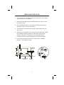
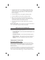
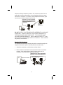
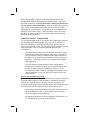
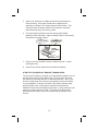
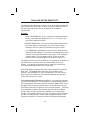
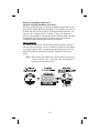
Digital Depth Sounder
OPERATING GUIDE
Contents
Unpacking . . . . . . . . . . . . . . . . . . . . . . . . . . . . . . . 2
Features . . . . . . . . . . . . . . . . . . . . . . . . . . . . . . . . 2
Installing the QT 206. . . . . . . . . . . . . . . . . . . . . . . . . . 3
Transducer Wiring . . . . . . . . . . . . . . . . . . . . . . . . . . . 4
Power Cable Wiring . . . . . . . . . . . . . . . . . . . . . . . . . . 4
Installing The Transducer . . . . . . . . . . . . . . . . . . . . . . . 5
Transom Mount Transducers . . . . . . . . . . . . . . . . . . . . . 5
Through-the-hull Transducers . . . . . . . . . . . . . . . . . . . . 8
Low Profile Transducers . . . . . . . . . . . . . . . . . . . . . . . 9
Stem-type (power Boat Bronze) Transducers . . . . . . . . . . . . 10
Inside-the-hull Transducers . . . . . . . . . . . . . . . . . . . . . 12
Understanding Sonar . . . . . . . . . . . . . . . . . . . . . . . . 14
Air Echoes . . . . . . . . . . . . . . . . . . . . . . . . . . . . . . 14
Setting The Shallow Water Alarm . . . . . . . . . . . . . . . . . . 15
Shallow Water Sensitivity . . . . . . . . . . . . . . . . . . . . . . 16
When to Use Less Sensitivity . . . . . . . . . . . . . . . . . . . . 17
When to Use More Sensitivity . . . . . . . . . . . . . . . . . . . . 18
Troubleshooting Guideline . . . . . . . . . . . . . . . . . . . . . 19
Features, Specifications, and availability of Optional Accessories are all
subject to change without notice.
1
UNPACKING
Your QT-206 Depth Sounder box should contain the following items:
• Transducer with 3 lugs attached
• Power Cable (attached to the gauge)
• Mounting Bracket and hardware
• This Operating Guide
If any items are missing or damaged, please contact your dealer
immediately.
FEATURES
n
Depth Readings – The QT-206 is designed to give depth readings
from 2.5 feet to a maximum depth of 199 feet. Depth readings are in
1/10 foot increments from 2.0 feet to 15 feet, and are shown as whole
numbers up to 199 feet. These readings are displayed on a large
Liquid Crystal Display (LCD).
n
Night Viewing – The QT-206 is back lit at all times with a soft
glowing lamp designed to help your night time navigational needs.
2
INSTALLING THE QT-206
1. Find a location on your dash panel which will provide clear viewing
and access to the LCD window.
2. After finding the right location for the indicator unit, mark a 2-inch
hole to be cut out.
3. Check behind the panel for any cables or wiring which could be
damaged. Then cut out the 2-inch hole.
4. Test fit the unit in the hole, and make any adjustments with your
saw or drill.
5. Extending out of the back of the instrument is a brass shaft. Attach
the U-shaped mounting bracket over this shaft, and place the
washer on the shaft. Thread the nut onto the shaft until the
U-shaped bracket is firmly against the back of the dash panel.
6. Look at the front of the instrument to ensure that it is aligned
properly. Then tighten securely.
1/2"
BRASS STUD
P/N: 210-005
2 3/8"
Less
Shallow
Sensitivity
More
2"
X-ducer
2 1/2"
Red
Black
Shield
NUT
P/N: 3203-009
MOUNTING BRACKET
P/N: 950-025
WASHER
P/N: 308-029
3
Power
Alarm
+
TRANSDUCER WIRING
On the rear of the unit, locate the terminal lugs extending out of the rear
of the instrument. These terminals are used to connect the transducer
wires.
When shipped from the factory, the transducer is wired with 3 female
lugs attached. These lugs need to be inserted onto the male terminals
located on the rear of the gauge.
The BLACK terminal is connected to the BLACK wire. The WHITE
terminal may be connected to either the RED, BLUE, or WHITE wire.
Connect the shield to the position marked “SHIELD”.
BLACK
SHIELD
RED, BLUE, OR WHITE
If you need these female lugs, contact your Uniden Marine dealer.
POWER CABLE WIRING
Because the QT-206 has no ON/OFF switch, you will need to wire it
directly to a power source which will turn the unit on as power is applied.
It may be convenient to wire the power cable directly to the Ignition
Switch so that when you turn the boat on, the depth sounder immediately
starts working. Some boats have already been prewired and labeled for
a depth sounder so that when the switch is turned ON, the depth
sounder receives power.
Another method for cable wiring is as follows:
4
1. Connect the main unit to a 12-volt battery using the power cable
supplied with your unit. You may extend this cable as necessary,
but you must observe proper polarity (i.e., RED is positive and
BLACK is negative).
2. Connect the BLACK wire to the negative (-) battery terminal.
3. Connect the RED wire to the positive (+) battery terminal.
4. Make sure the connections are clean and tight so they do not
vibrate loose during the boat’s operation. Occasionally clean any
accumulated corrosion from the battery terminals.
5. If for some reason the fuse is blown, replace with a 1 amp fuse,
normal blow.
DO NOT OVER FUSE! The unit consumes 0.25 amps of current when it
is on. You will want to keep your battery fully charged.
INSTALLING THE TRANSDUCER
The three most popular transducer styles are:
• TRANSOM MOUNT – Ideal on boats with outboard engines, or on
I/O driven boats.
• THROUGH-THE-HULL – Ideal for boats with Inboard engine(s).
• INSIDE-THE-HULL – Often called “Shoot Through Transducer”; it
can be used effectively if installation procedures are followed
carefully.
TRANSOM MOUNT TRANSDUCERS
Selecting An Installation Location
Mount the transducer fairly close to the centerline (keel) of the boat,
which will ensure minimum potential aeration over the acoustic window
of the transducer. On twin drive installations, install the transducer
between the drives.
On single drive installations, you should mount the transducer bracket on
the side of the boat where the propeller blade is rotating downwards.
This is usually the right (starboard) side. If possible, do not mount the
5
transducer directly behind any strakes, ribs, intakes and outlets for live
wells and/or engine cooling water, or any protrusion which may cause
turbulence or cavitation. On slower, heavier displacement boats, good
results can be achieved further from the keel.
FIBERGLASS V-HULL BOATS—TWIN ENGINE
(MODERATE TO DEEP-VEE DEADRISE ANGLE)
FIBERGLASS V-HULL MODERATE TO
LARGE DEADRISE
TRANSDUCER IS BELOW
STRAIGHT LINE
EXTENSION OF HULL.
HULL
DO NOT INSTALL YOUR TRANSDUCER UNDERNEATH A GASOLINE
OVERFLOW. THIS WILL DESTROY THE PLASTIC MATERIAL OF
THE TRANSDUCER AND THE BRACKET. THIS DAMAGE IS NOT
COVERED UNDER WARRANTY. Also, do not use LOCKTITE® or any
other solvents on the mounting hardware or transducer. These materials
may destroy the transducer.
Mounting The Transducer
The transducer and bracket assembly should be oriented vertically with
respect to the water to yield a vertically-directed acoustic beam.
1. Attach the transducer to the bracket as shown below.
2. Place transducer and bracket at the selected location on the boat
transom. Align the bracket so that the bottom surface of the
transducer is even with the underside of the boat.
FIBERGLASS V-HULL BOATS—TWIN ENGINE
(MODERATE TO DEEP-VEE DEADRISE ANGLE)
HULL
WEDGE POINTING FORWARD
INSTALL BETWEEN DRIVES—MODERATE TO
DEEP-VEE DEADRISE ANGLE
DEADRISE ANGLE
(Install between drives)
6
3. Mark the outline of each slot on the hull. Mark the screw locations
1/8" from the bottom of each slot, and drill four holes 3/4" deep with
a 9/64" drill. The slots in the bracket allow 5/8" of vertical
adjustment which can be utilized to lower the transducer further
into the water to achieve optimal performance.
4. Using the sheet metal screws provided, attach and tighten the
bracket to the hull so that the transducer projects 1/8" below the
underside of the hull. A marine sealant such as RTV should be
applied to the threads of the screws to prevent water seepage into
the transom. Align the transducer so that the rear is 1/16 to 1/8"
lower than the forward point (bow). Tighten all bolts and screws.
5. Route the cable to the QT-206, being careful not to tear the cable
jacket. Make sure the cable is separated from the ignition,
tachometer, alternator, or other electrical wiring. Do not remove
the connector or splice or shorten the cable, as this will void the
transducer warranty.
Transducer Replacement/Identification Tag
On most transducers manufactured after 1987, the operating frequency
and part number is attached to the cable or is printed on a mylar tag near
the connector end. Do not remove this tag since it identifies the
transducer and will help you identify the operating frequency of the
transducer. The QT-206 operates at 200 kHz. (Incorrect frequency will
cause your instrument to operate improperly.)
Transducer Wetting
Immediately before launching your vessel, thoroughly wipe the face
of the transducer with a detergent type liquid soap. This reduces the
amount of time required for the transducer to establish good contact with
the water. If this procedure is not followed, it may take several days for
the complete “wetting” to occur, resulting in reduced performance of the
instrument.
Transducer Painting
If a vessel is kept in saltwater, especially in the southern U.S., marine
growth can accumulate rapidly on the transducer face and seriously
reduce performance. If fouling does occur, use a stiff brush or putty knife
to remove this growth. Wet sanding of the fouled transducer face is
permissible with #220 or finer grade of wet or dry emery paper. (Use
plenty of water.) Coating transducers with anti-fouling paint is often
necessary to achieve consistent performance. All anti-fouling paints
7
have a solvent base. However, some solvent bases will damage
encapsulation materials and plastics to varying degrees. If you need
anti-fouling protection, use only paints with a mineral spirits base; do
not use acetone vinyl-based paints. Glochester (RULE) Durapoxy is a
hard, mineral spirits-based paint that has been found to be virtually
transparent to acoustic energy. Never apply paint to the transducer by
spraying; use a brush or roller. A sprayed surface “wets” very slowly,
and there are often microscopic air pockets under the surface which
attenuate the sound energy.
THROUGH-THE-HULL TRANSDUCERS
The two most popular styles of Through-the-Hull Transducers produced
are low profile types, which typically are 1-3/4" or 2" in diameter, or
stem-type transducers, which typically have a 3/4" pipe thread and
require a fairing block to level. The two most popular materials used are
nylon and bronze. Choice of material depends upon the boat
construction:
Wooden boats require the use of a bronze transducer or bronze
fittings because when the boat is out of the water, the wood will
dry out. When the fitting is installed and the boat is returned to
the water, the wood will swell and possibly crack a nylon type of
transducer. Therefore, bronze is recommended for all wooden
boat applications.
Larger fiberglass boat manufacturers often request bronze
transducers and fittings due to the size of the boat and the total
number of fittings used in the installation. However, nylon
transducers are better suited for this application because of their
ease of installation, lower cost, and more complete seal to the
fiberglass hull.
Selecting an Installation Location
The mounting location must provide a smooth flow of water over the face
of the transmitting surface of the transducer. Bubbles will cause the
instrument to read improperly and cause erroneous readings. The
mounting location should have reasonable access from inside the vessel
since the transducer will require tightening from inside the hull.
• On sailboats, mount the transducer where the acoustic beam will
not be shaded by the keel. A spot forward of a fin keel with a
minimum deadrise angle is preferred.
• On planing powerboats, locate the transducer off centerline 6" to
12" and before the first lifting strake (flat area).
8
• Do not install it on a lifting strake since this is the area where air
bubbles travel from the bow to the stern, to provide a smooth ride.
• On displacement power boats (trawlers), mount the transducer
well aft and close to the centerline.
• On I/Os, mount the transducer close to the engine(s).
• On inboards, always mount the transducer well ahead of the
propeller(s), and shafts.
IMPORTANT
Never mount a transducer in direct line or within 4 feet behind another
through-hull fitting, the keel or rudder, zinc anodes, or other
projections that would cause turbulence around the transducer when
the boat is underway.
LOW PROFILE TRANSDUCERS
The low profile style of transducer is ideal for high speed sport boats and
sailboats. This style of transducer is designed to be mounted flush
against the hull without a fairing or leveling block. The hull deadrise
angle must not exceed 10° in order to use this transducer fitting.
Mounting the Transducer
1. Drill a 1/8" pilot hole in the preferred transducer location.
2. Drill a 1-3/4" or 2" hole through the hull using the pilot hole as a
guide.
3. Have some type of soft backing plate or thin piece of plywood
(3-1/2" x 3-1/2" x 1/4" thick) available to strengthen the inside of the
hull around where the hole was drilled. This serves the dual
purpose of allowing the transducer to conform to the inside of the
hull while preventing the transducer lock nut from unwinding. If you
have a plastic housing, do not use wood shim. Use a fiberglass,
plastic, or brass washer instead.
4. Route the transducer cable through the hole in the hull.
IMPORTANT
Do not pull on the cable as this may cause internal damage to the
transducer by causing an internal wiring short.
9
5. Apply a 1/8" thick layer of sealant around the lip of the plastic or
bronze housing. A thin layer should also be applied up the
sidewalls to a height of 1/4" greater than the hull thickness. This
will ensure there is sealant material in the threads to seal them,
and hold the housing nut securely in place.
6. From the outside of the hull, push the housing (with sealant
applied) into the drilled hole. Apply a twisting motion to the housing
to squeeze out excess sealant.
GASKET
(OR RUBBER)
HULL
SEALANT
7. Put the nut on the transducer from the inside of the hull. If nylon,
hand tighten only.
8. Clean off any excess sealant from around the transducer.
STEM-TYPE (POWER BOAT BRONZE) TRANSDUCERS
The stem-type transducer is popular as a replacement transducer since it
was the primary style used on older boats. The stem will fit the same
size hole as a previously defective or obsolete transducer. Also, if your
hull has a steep dead rise, the stem-type transducer will be best suited
for your application. However, because of the smaller diameter shaft
going through the hull, a fairing block should be used so that the
transducer can be oriented straight up and down. Fairing blocks are best
made out of hard wood such as oak. The shape of the block will be
determined by the shape of your hull and the style of transducer you
choose.
10
3/4"
PIPE
THREAD
4"
FAIRING
BLOCK
HULL
1 1/4 "
3"
Mounting the Transducer
1. Drill a 1/8" pilot hole in the preferred transducer location. Refer to
the previous section to determine the best location for your type of
boat.
2. Drill a hole “slightly” larger than the stem of the transducer. Be
careful not to make it too large as you will run the risk of water
leaking into the hull.
3. Cut the fairing block to the shape of your hull and insert the cable
and stem of the transducer through half of the fairing block.
4. Apply a good grade of underwater marine sealant (polysulfide
compound) to the flange on the transducer and to the surface of
the leveling block where the block touches the outside of the hull.
Apply enough sealant so that it beads out around the transducer as
you tighten the transducer nut.
5. Put the remaining half of the fairing block on the inside, over the
transducer, along with sealant next to the hull. Tighten lightly with
a wrench.
6. Clean off the excess sealant from around the transducer.
IMPORTANT
After launching the boat, be certain to check the transducer location
for leaks.
11
INSIDE-THE-HULL TRANSDUCERS
This type of transducer does not require the drilling of a hole as does the
Through-the-Hull Transducer. However, since the sound waves
transmitted and received by the Inside-the-Hull Transducer must pass
through the hull, transducer performance will be reduced. The success
of Inside-the-Hull installation is greatly dependent upon the purity of the
hull directly below the transducer and the type of hull. Inside-the-Hull
mounting should not be used on aluminum hulls, balsa core hulls,
wooden hulls, or hulls where the deadrise angle is more than 15°.
To reduce sound transmission losses, the adhesive used to bond the
transducer to the hull should conduct sound at speeds close to that of
the plastic or epoxy face of the transducer and the polyester resin of the
hull. Epoxy adhesives, as opposed to silicone, are recommended.
Note: When performing an Inside-the-Hull installation, you must use
a special Inside-the-Hull Transducer since it contains a
transducer crystal which is wider in diameter, and is designed
to transmit the pulse through the hull. Do not attempt to use
a Transom Mount Transducer, as the crystal is too small to
ensure optimum instrument results.
Selecting an Installation Location
The transducer should be located where the hull laminate is dense and
has no entrapped air. Generally, best operation is obtained by mounting
the Inside-the-Hull Transducer on the centerline of the hull, as it allows a
flat, horizontal mounting area for vertical orientation of the sonic beam.
Do not choose an area above a lifting strake, as air travels underneath
the hull here and could cause erroneous readings.
• On sailboats, mount the transducer near the centerline and
forward of the leading edge of the keel.
• On power boats, mount the transducer as far aft as practical.
• On I/Os, mount in a spot near the engine.
• On inboards, locate the transducer forward of the prop(s), where it
will not be shaded by prop shafts.
12
Use one of the following methods to determine if your chosen location is
satisfactory:
1. Place the transducer in a plastic bag filled 1/2 to 3/4 full of water.
Tie or tape the bag tightly around the transducer cable. Wet the
selected location and place the bag against the hull, pressing the
transducer face against the hull. If the hull is void free at this point,
the depth sounder should now operate.
2. Coat the face of the transducer with silicone grease or petroleum
jelly. Then press with a twisting motion against the hull. If the hull
is void free at this point, the depth sounder should now operate.
Mounting the Transducer
1. If the interior surface of the hull at the selected spot has a rough
pattern, grind it with a disc sander until smooth. Any grease or oil
on the surface must be removed.
2. Mix the two-part epoxy supplied with the transducer for at least 3
minutes. If this is not done, proper bonding of the transducer to the
hull will not occur and false readings can occur. The working time
of the epoxy is 5 minutes. The hull temperature must be 60° or
higher for the epoxy to bond sufficiently.
3. Apply the mixture to the clean location on the hull and to the face of
the transducer in a small amount.
4. Press the face of the transducer into the spot of epoxy. To remove
any air bubbles, slowly rotate in one direction only, until the
transducer is physically against the hull or within 1/4" of the hull.
INSIDE THE HULL
THIN LAYER OF
2-PART EPOXY
HULL
No more than 15 Degrees
When the epoxy has cured, it should be permanently bonded to the hull
and hard to the touch. Test the epoxy which extends out of the
underside of the transducer with a screwdriver to ensure that it can’t be
dented, and that it is completely hard. Epoxy which is not hardened will
eventually cause improper readings.
13
UNDERSTANDING SONAR
All depth sounders emit ultrasonic sound signals from the transducer into
the water located under your boat. These sound signals travel through
the water at a rate of approximately 4,800 feet per second (1500 meters
per second). The depth sounder transmits a signal and receives a
returning echo. The unit calculates the amount of time in microseconds
that elapsed while the signal traveled down to the bottom and returned
back to the transducer. This time is then converted to depth and
displayed on the screen.
It may help to understand these sound signals traveling between the
transducer and the bottom by imagining a ping-pong ball bouncing up
and down from the floor. The closer the ball is to the floor, the less time
it takes for it to return. The higher the ball is bounced, the longer it takes
to return. Bouncing the ball off a hard surface such as cement is the
same as bouncing a signal off a sandy or hard bottom. Bouncing this
same ball off carpeting creates a totally different effect because the ball
returns with less force. The same principle applies to an echo bouncing
off a muddy or grassy bottom, causing the echoes to be weaker.
AIR ECHOES
Air echoes can be caused by excessive turbulence under the face of the
transducer. Ultrasonic signals from a transducer will not penetrate air.
They react to air in the same manner as they react to a hard bottom
described above. Therefore, if your transducer is not mounted properly
and you are getting turbulence (air bubbles) under your transducer, you
may get false readings. This is simply because signals are being
returned by the turbulence and are never reaching the bottom.
14
SETTING THE SHALLOW WATER ALARM
Located just below the LCD window are two keys labeled “DOWN” and
“UP” Alarms. These keys are used to set the Shallow Water depth alarm
so that it will audibly alert you if you enter water shallower than your
preset depth alarm.
To set the alarm, press the “DOWN” key. The LCD shows an alarm
depth of A03. Pressing the “DOWN” continuously cycles the alarm
setting deeper by one foot increments from A03 through A10 (for
example: 3, 4, 5, 6, 7, 8, 9, 10). After A10, the alarm settings are by
2-foot increments (for example: 10, 12, 14, 16, 18, 20 feet). The alarm
settings jump by 5-foot increments (for example: A20, A25, A30).
When you see a digital readout proceeded by an “A”, this is your ALARM
setting. This number appears in the display window immediately after
you press either alarm key and then will disappear after several seconds.
This number remains in the unit’s memory until power is turned off.
To decrease the alarm setting, press the “UP” key. The display will show
these numbers in decreasing value so that the alarm is shallower.
Several seconds after you press either the “UP” or “DOWN” keys, the
instrument displays the actual depth reading. A00 indicates the alarm is
off.
15
SHALLOW WATER SENSITIVITY
The Shallow Water Sensitivity controls a circuit in the depth sounder that
affects the first 10 feet of water. It alters the system’s response time in
this area only, and can be used to compensate for installation
imperfections.
Example:
• SHALLOW READINGS: If your instrument occasionally displays
random, false shallow readings such as 3.1’, 2.8’, and 4.3’, you
may need to adjust this control.
• DEEPER READINGS: If your unit is reading false echoes which
are deeper than the actual depth, you may not have enough
sensitivity, which can also be corrected by using this control.
• “0.0” READINGS: Adjusting this control too far in either direction
could affect your readings. For example, if the adjustment is at an
extreme, it could actually cause the unit to give a “0.0” reading at
a deeper depth. The true depth could be 30 feet, and if the
control is too far counterclockwise, the readout could be “0.0”.
This adjustment fine tunes the installation of your gauge to the location of
the transducer on your boat and to the waters where you do your
boating. It is typically an adjustment that is made by the boat owner
since it is performed while the boat is in the water.
Each depth gauge is tested at the factory with a transducer located in a
water tank. The Shallow Water Sensitivity is then factory preset.
However, after installation for your local waterways, you may need to
perform this minor adjustment so that the depth gauge operates at its
maximum potential on your boat.
With Inside-the-Hull Transducer installations, it is especially important
to perform this adjustment. It is impossible to control the many types of
hull configurations on the many varieties of boats available today. Since
fiberglass hulls are generally hand-layered, the hull thickness can vary
from boat-to-boat even though they may be the same model. Thickness
of the fiberglass combined with the many types of bottom conditions
(sandy, rocky, muddy) can affect the readings on your digital depth
sounder. This control enables you to tune your gauge more precisely so
that the unit reads properly. Unless major changes take place in your
boating environment, you should not need to adjust this setting again.
16
WHEN TO USE LESS SENSITIVITY:
SHALLOW READINGS
Use less sensitivity when your instrument displays a series of random,
shallow readings (3.5’, 2.9’, 4.1’) and the actual depth is greater.
How to Perform
When looking at the rear of the instrument, this adjustment is made in a
clockwise direction. (This control operates much like the volume control
on a radio. If you turn it all the way down, you cannot hear the music.
Turning it up too far makes the music blare and sound out of tune.)
Turning the sensitivity control too much can actually “squelch” out the
transmit pulses and the return echoes. This will result in a “0.0" reading
in the display window.
Note: When making this adjustment, turn the control no more than
1/16th of a turn at a time. Then wait 3 to 4 seconds before
making the next adjustment turn.
17
WHEN TO USE MORE SENSITIVITY:
DOUBLE ECHOES (READINGS TOO DEEP)
Use more sensitivity when your instrument displays depths that are too
deep; that is, greater than the actual depth. For example, if you are in 6’
of water and turn this control too far in the less sensitivity direction, you
may see “12.0’” appear in the LCD window. This is very dangerous
since you will actually be operating the boat in shallower water than what
is displayed. Caution should be exercised to locate the Sensitivity
Control somewhere between both ends of the rotation.
How To Perform
By rotating the control in a counterclockwise direction (when looking at
the rear of the instrument), you can increase the sensitivity of the gauge
to the first 10 feet of water. Increasing this adjustment too much in the
MORE SENSITIVITY direction can cause a “doubling” of the actual
depth.
Note: When making this adjustment, turn the control no more than
1/16th of a turn at a time. Then wait 3 to 4 seconds before
making the next adjustment turn.
18
TROUBLESHOOTING GUIDELINE
Symptom
“0.0" is flashing in the
display window.
Possible Reasons
Unit is not receiving an
echo which could be
caused by a variety of
reasons:
Suggested Solutions
Correctly adjust the
Sensitivity Control so
that the numbers in the
display window start to
appear and are reading
the correct depth.
Sensitivity Adjustment
was turned too much in
one direction, actually
Try a “known good”
squelching out the echo. transducer hooked up to
the gauge and see if the
Transducer is defective, depth appears in the
therefore not transmit- window. It is important
ting or receiving echoes. to “wet” the transducer
immediately before imInstallation of the trans- mersing in the water.
ducer is incorrect,
therefore not allowing a Make sure that the
pulse to be transmitted transducer is installed
or received.
per the instructions in
Unit is defective and
this manual. Insideneeds to be returned to the-Hull Transducers
the factory for repair.
must be properly
bonded and attached to
the hull as described in
the section on Insidethe-Hull mounting, or
must be properly installed by the boat
manufacturer if the
equipment was installed
at the boat factory.
Unit is showing “88.8"
in the display window.
A logic circuit failure
probably caused by a
poor solder connection,
lack of solder, or improper wiring.
19
If all of the above tests
resulted in “0.0" remaining in the window, return
the unit for repair.
Return unit to the factory for repair.
Symptom
Unit is not reading properly at high speeds,
causing high random
numbers at high RPM.
Possible Reasons
There are three basic
types of installations:
Inside-the-Hull,
Through-the-Hull, and
Transom Mount. Generally, this situation is
attributed to the location
and installation of the
transducer. A great
deal of air is flowing
over the face of the
transducer and is inhibiting the unit from receiving the correct
bottom reading.
Cavitation (locked on
bubbles) either on the
face of the transducer or
on the underbelly of the
boat is preventing the
unit from displaying the
true depth.
Suggested Solutions
Refer to the pages in
this manual along with
the drawings for your
particular boat on the
proper installation technique.
If this is a Transom
Mount Transducer, it
may require that the
transducer be adjusted
lower in the bracket so
that it extends further
under the bottom of the
boat and is allowed a
clean flow of water.
It could also require that
the transducer and/or
bracket be relocated to
achieve a clean, smooth
flow of water over the
face of the transducer.
Transom Mount Trans- This occurs if the trans- Transducer may be perducer is breaking where ducer is installed under manently damaged and
the mounting bracket at- a gasoline overflow vent is non repairable. Betaches to the transOR if an adhesive such fore installing a replaceducer.
as LOCKTITE® was
ment -transducer, be
used to bond the hard- sure to move the
ware onto the transbracket.
ducer mounting bracket.
The adhesive or gasoline has eaten into the
plastic and cannot be
repaired.
A30 or A00 reads out
A lug from a transducer Unfortunately, permapermanently on the dis- wire was accidentally
nent damage has been
play.
connected to either the done to the main surAlarm Up/Down terminal face mount “chip”. The
and power was applied. instrument head only
must be returned for repair.
20
One Year Limited Warranty
WARRANTOR: UNIDEN AMERICA CORPORATION (“Uniden”)
ELEMENTS OF WARRANTY: Uniden warrants, for one year, to the original
retail owner, this Uniden Product to be free from defects in materials and
craftsmanship with only the limitations or exclusions set out below.
WARRANTY DURATION: This warranty to the original user shall terminate and
be of no further effect 12 months after the date of original retail sale. The
warranty is invalid if the Product is (A) damaged or not maintained as
reasonable or necessary, (B) modified, altered, or used as part of any
conversion kits, subassemblies, or any configurations not sold by Uniden, (C)
improperly installed, (D) serviced or repaired by someone other than an
authorized Uniden service center for a defect or malfunction covered by this
warranty, (E) used in any conjunction with equipment or parts or as part of any
system not manufactured by Uniden, or (F) installed or programmed by anyone
other than as detailed by the Operating Guide for this product.
STATEMENT OF REMEDY: In the event that the product does not conform to
this warranty at any time while this warranty is in effect, warrantor will repair the
defect and return it to you without charge for parts, service, or any other cost
(except shipping and handling) incurred by warrantor or its representatives in
connection with the performance of this warranty. THE LIMITED WARRANTY
SET FORTH ABOVE IS THE SOLE AND ENTIRE WARRANTY PERTAINING
TO THE PRODUCT AND IS IN LIEU OF AND EXCLUDES ALL OTHER
WARRANTIES OF ANY NATURE WHATSOEVER, WHETHER EXPRESS,
IMPLIED OR ARISING BY OPERATION OF LAW, INCLUDING, BUT NOT
LIMITED TO ANY IMPLIED WARRANTIES OF MERCHANTABILITY OR
FITNESS FOR A PARTICULAR PURPOSE. THIS WARRANTY DOES NOT
COVER OR PROVIDE FOR THE REIMBURSEMENT OR PAYMENT OF
INCIDENTAL OR CONSEQUENTIAL DAMAGES. Some states do not allow
this exclusion or limitation of incidental or consequential damages so the above
limitation or exclusion may not apply to you.
LEGAL REMEDIES: This warranty gives you specific legal rights, and you may
also have other rights which vary from state to state. This warranty is void
outside the United States of America.
PROCEDURE FOR OBTAINING PERFORMANCE OF WARRANTY: If, after
following the instructions in this Operating Guide you are certain that the
Product is defective, pack the Product carefully (preferably in its original
packaging). Include evidence of original purchase and a note describing the
defect that has caused you to return it. The Product should be shipped freight
prepaid, by traceable means, or delivered, to warrantor at:
Uniden America Corporation
Parts and Service Division
4700 Amon Carter Blvd.
Ft. Worth, TX 76155
(800) 586-0409, 8 a.m. to 5 p.m. Central, Monday through Friday
©1995,1996 Uniden America Corporation
Printed in the United States of America
All rights reserved.
OMQT206