1
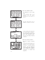
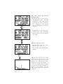
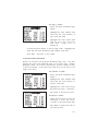
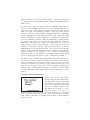
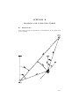
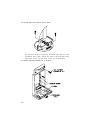
Remove the E-ring from the special screw under the base using a pair
of pliers.
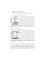
· Remove the lever. A spring and detent pin are contained within a
recess on this lever.
· Unscrew the special screw and remove it from the base.
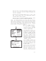
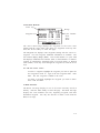
· The base, lever, detent pin, detent spring, plastic spacer, and wave
washer may be set aside (these parts are not used for surface
installation).
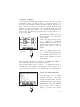
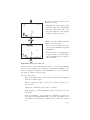
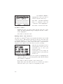
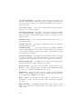
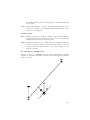
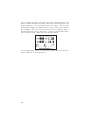
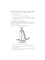
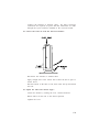
· Loosen the coinslot screw and slide the cradle to mid position
revealing 3 countersunk holes as shown in the figure at the bottom
of page C-5.
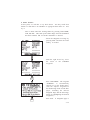
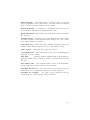
· Mount the surface mount to the dash using appropriate screws (#8
100o flat head screws are recommended).
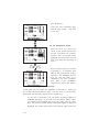
To adjust the universal mount...
C-7