1
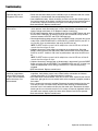
Troubleshooting
SYMPTOM
POSSIBLE SOLUTION
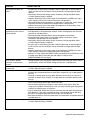
Operator does not run.
Diagnostic LED not on.
• Power not connected. Make sure the AC/Solar input is connected and that at least
one battery is connected with the corresponding fuse intact.
• Low or defective battery. Check the battery to make sure that the red wire goes to
the positive terminal of the battery and the black wire goes to the negative terminal
of the battery. Replace the battery if the open circuit voltage is below 11.5Vdc.
• Bad control board. Replace control board.
• Low or defective battery. At least one charged battery must be connected for the
unit to operate. Verify the battery fuse is intact. Check battery connections and
battery voltage to be above 11.5V Replace batteries if necessary.
• STOP button connection loose or disconnected. Press the RESET button and verify
that the STOP LED lights up and then turns off after 10 seconds. Verify the wire
connects between the STOP and CTRL PWR terminals.
• Obstruction blocking safety sensors. Press the RESET button and verify that all the
safety LEDs (OPEN EDGE/PHOTO, OPEN PHOTO, CLOSE PHOTO) are OFF. If
any are ON, clear any obstructions and verify the LED turns off
Operator powers up but
does not run.
NOTE: The RESET button may need to be hit multiple times since the LEDs turn off after 10
seconds when the unit goes to sleep.
• (Optional Accessory) Safety edge is damaged or on an obstruction. Press the
RESET button and verify that the Safety LEDs (OPEN EDGE and CLOSE EDGE/
PHOTO) are OFF. If either is ON, clear any obstructions and verify the LED turns
off.
•
Relays “click” when remote
control or single button
control (SBC) command
is given, but the operator
does not move or arm
disconnected.
•
•
•
•
•
NOTE: The RESET button may need to be hit multiple times since the LEDs turn off after 10
seconds when the unit goes to sleep.
(Optional Accessory) Interrupt loop or Shadow loop is obstructed. Press the RESET
button and verify that the INTERRUPT and SHADOW LEDs are OFF. If either is on,
check the loop detector and its wiring to insure that it is not incorrectly being
triggered.
Bad control board. Replace control board.
Battery not connected. At least one charged battery must be connected for the unit
to operate. Verify battery fuse is intact. Check battery connections and battery
voltage to be above 11.5V. Replace batteries if necessary.
Arm cable loose or disconnected. Verify that all of the wires, especially the red and
blue wires, going to the arm are secure and that the connector is properly mated to
the header.
Arm is jammed or incorrectly installed. Disconnect the motor housing from the arm
and verify that the arm moves freely. With the motor housing still disconnected,
enter the Learn Limits mode and verify that the motor spins. Reconnect the motor
housing to the arm and make sure that all 4 screws are securely tightened and that
the motor seats correctly against the worm drive. Relearn limits for the operator.
Bad control board. Replace control board.
41
Operation and Maintenance