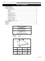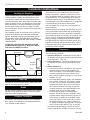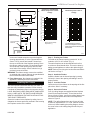
1
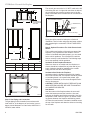
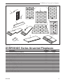
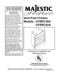
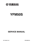
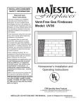
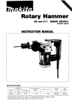
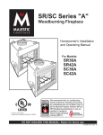
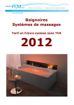
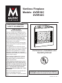
Ventless Fireplace
Models: UVDR36C
UVDR42C
INSTALLER/CONSUMER
SAFETY INFORMATION
Read and save
these instructions.
This book contains your installation instructions and should be kept in a safe place. For
you to realize all the advantages and use of
the reliable service that has been engineered
into your CFM Corporation fireplace, you
must carefully follow all of the instructions
contained in this book regarding installation
and operation of the fireplace.
These instructions should be read carefully
in their entirety before beginning installation
of the fireplace.
It is suggested that you wear work gloves
and safety glasses to protect your hands and
eyes when installing your fireplace. NOTE:
Authorities having jurisdiction (i.e. building
inspectors, fire marshals, etc.) should be
consulted before installation to determine the
need to obtain a permit.
When installing the Blower Kit, it is necessary to bring the power source to the fireplace before walls are enclosed. Refer to
Blower Kit instructions.
Homeowner’s Installation and
7469
Operating
Manual
UVDR36/42C
cover
2/04
These fireboxes are approved as universal fireboxes and can be paired with any
ANSI Z21.11.2 approved vent-free log set.
The vent-free log manufacturer’s instructions - including their required dimensional clearances for firebox size, - must
be followed.
Refer to the manual that is packed with the
log set for operating instructions.
Not for use in bedroom or bathroom installations.
INSTALLER: Leave this manual with the appliance.
CONSUMER: Retain this manual for future reference.
20007469 9/07 Rev. 5
UVDR Series Unvented Gas Fireplaces
Table of Contents
Hearth Dimensions ........................................................................................................................ 2
Fireplace Dimensions .................................................................................................................. 3
Installation Instructions ............................................................................................................... 4
Locating the Fireplace ........................................................................................................ 4
Gas line .............................................................................................................................. 4
Drafts .................................................................................................................................. 4
Clearances ......................................................................................................................... 4
Installing the Firebox .......................................................................................................... 5
Finishing the Fireplace ....................................................................................................... 7
Hearth Extension ................................................................................................................ 7
Pre-wiring of Junction Box .................................................................................................. 7
Electrical Services .............................................................................................................. 7
BL-4 Blower Installation ...................................................................................................... 8
UVDR36C Installation......................................................................................................... 8
UVDR42C Installation......................................................................................................... 8
Install Optional Outside Air Kit ............................................................................................ 9
Replacement Parts ..................................................................................................................... 11
Accessories ................................................................................................................................ 12
Servicing ..................................................................................................................................... 12
Warranty ...................................................................................................................................... 15
UVDR36C, UVDR42C
Certified To
ANSI Z 21.91a - 2002
Ventless Fireboxes
for use with
any ANSI Z21.11.2
Unvented Room Heaters
Units:
UVDR36C
UVDR42C
GF1VF2
GF1VF4
B
C
A
FP1531
Front Width
Back Width
Depth
A
UVDR36C
UVDR42C
C
FP1531 B
hearth
dimensions
35”
23¹⁄₈”
16¹⁄₄”
djt mm) (413 mm)
(889 mm) 9/04 (589
32⁷⁄₈”
18¹⁄₂”
40³⁄₄”
(683 mm)
(559 mm) (451 mm)
Fig. 1 Hearth dimensions.
2
20007469
UVDR Series Unvented Gas Fireplaces
Fireplace Dimensions
P
Rough
Opening
Depth
K
L
N
H
P
1/2” Clearance to
Combustibles not Required
at this Point
Rough
Opening
Height
M
1/2” Clearance to
Combustibles
not Required
at this Point
Rough Opening Width C
F
E
A
J
Gas Line
Access
G
B
E
6���" D
C
Fig. 1a UVDR36/42C specifications and framing dimensions.
A
B
C
D
E
F
G
H
J
K
L
M
N
P
20007469
UVDR36C
36”
21⁷⁄₈”
39”
7”
35”
38¹⁄₄”
9”
21”
8⁵⁄₈”
22”
21”
65”
32¹⁄₂”
46”
UVDR42C
42”
21⁷⁄₈”
45”
78984
ADF36/42C
8”
SPECS
39”
2/04
42¹⁄₄”
10¹⁄₂”
22”
9³⁄₄”
32”
22”
76¹⁄₄”
38¹⁄₈”
54”
3
UVDR Series Unvented Gas Fireplaces
Installation Instructions
Locating the Fireplace
Figure 2 shows some of the many ways your fireplace
may be installed. Consider the traffic pattern in your
room and the location of doors and windows. Moving
air from ceiling fans, open doors and hot air grilles may
cause the flames to soot. If a disturbance is found that
effects the flames, it must be eliminated by turning off
the ceiling fan, closing the door or closing or moving
the hot air register. A corner location may be best where
space is limited.
Your fireplace weighs no more than some of your fine
furniture. If the fireplace is located near a load bearing wall, additional supports to the foundation will not
be necessary. HEAVY FACINGS SUCH AS BRICK,
STONE, ETC., MAY REQUIRE ADDITIONAL FOUNDATION SUPPORT.
ALTHOUGH THIS UNIT MAY BE INSTALLED ON
COMBUSTIBLE SURFACES, IT MUST NOT BE INSTALLED ON CARPET OR VINYL.
Room Divider
Partial Room
Projection
Full Room
Projection
Corner
Flush
T224
Fig. 2 Locating the fireplace.
Gas T224
Line
place fireplace
The gas line must be installed
before framing in the fire2/04
place by a licensed gas line installer.
Drafts
Do not locate the fireplace in high traffic areas or areas
exposed to high drafts and winds. Locate the fireplace
away from furniture and draperies.
Fireplace Clearances
The fireplace may be placed directly on a combustible
floor, against a combustible wall at marked clearances
or on a raised wooden platform.
4
If the fireplace is to be installed on a raised wooden
platform, the platform must be a continuous level surface. The fireplace must be secured in place so it cannot shift positions. The nailing flanges on the sides of
the firebox make securing it to the framing easy. They
were designed to allow the installation of 1/2” wallboard
or plywood flush with the face of the fireplace.
Only the header (Fig. 1) may rest on the standoffs on
top of the firebox.
When the fireplace is installed over carpeting, vinyl, tile
or any combustible material other than wood flooring, it
must be installed on a metal or wood panel extending
its full width and depth. Alternatively, the carpeting, vinyl
tile, etc., may be removed from beneath the fireplace
before installing. COMBUSTIBLE MATERIALS MUST
NOT BE INSTALLED OVER OR TOUCH ANY BLACK
PAINTED SURFACE. DO NOT BLOCK HEAT CIRCULATING AIR OUTLETS. DOING SO MAY RESULT IN
POTENTIAL FIRE HAZARD.
Clearances
To ensure a safe installation the following instructions
must be carefully observed.
1. Sidewall Clearances: Clearances from the side of
the fireplace opening to any combustible wall should
not be less than 5”. (Fig. 3a)
2. Ceiling Clearances: The ceiling height should not
be less than 42” from the top of the fireplace opening.
3. Mantel Clearances:
a. If the fireplace has no mantelpiece, then the heat
resistant material must extend upwards a distance of at least 9¹⁄₂" from the fireplace opening.
A mantel projection must be a minimum of 24”
above the top fireplace opening if a canopy is not
installed. (Fig. 3b)
b. Noncombustible materials used in this installation
such as slate, marble, tile, etc. must be at least
1/2" thick. Do not install a combustible material
behind sheet metal. Failure to use noncombustible materials above the opening as specified
in these instructions may cause damage to the
materials used and create a fire hazard.
c. A heat reducing canopy is shipped with the
fireplace. Use of this canopy is optional in order
to reduce mantel heights as shown in Figure 3d.
If the canopy is installed, a combustible mantel
piece may project 2" from the wall at 6¹⁄₂" above
the fireplace opening. A 6" mantel projection at
13" above the fireplace opening and a 10" projection at 22" above the opening. (Fig. 3a and 3d)
To install the optional canopy, remove the four (4)
screws supplied with a Phillips screwdriver. Two (2)
20007469
UVDR Series Unvented Gas Fireplaces
3a
3c
Clearance to Combustible
Mantel Projections without
Canopy
3d
Clearance to Combustible
Mantel Projections with 4”
Canopy
5" Min.
Combustible Perpendicular Wall
3b
10"
Clearances
without Canopy
6"
Noncombustible
Material
24"
Min.
Clearance* from Top of Fireplace Opening (“)
42"
24
22
22
20
20
18
18
16
16
14
14
12
12
10
10
8
8
6
9���"
Min.
FP604b
Fig. 3 Clearances to combustibles.
screws are located across the top of the fireplace
opening approximately 5” to the right and left from
center. Two (2) screws are located 4” down from
the top on each side of the fireplace opening. Place
the canopy, making
sure the 1/4” hex head screws
FP604a
across the top of clearances
the opening align with the clearance holes in the2/04
canopy. Secure with the four (4)
previously removed screws.
WARNING: The firebox canopy must not be modified
or replaced with a canopy that may be provided with
the unvented decorative room heater.
4. Floor Clearances: No clearance is required if the
appliance is installed per these instructions.
Installing the Firebox
This list of specific instructions will help you make certain that every installation operation is done correctly.
Complete the installation steps in the sequence shown.
LOCAL BUILDING CODES SHOULD BE CONSULTED
IN ALL CASES AS TO THE PARTICULAR REQUIREMENTS CONCERNING THE INSTALLATION OF FACTORY BUILT FIREPLACES.
Select the location for the fireplace by taking into consideration the factors previously outlined in the Locating
the Fireplace section of the manual.
20007469
4
6
8
10
Mantel (Combustible)
Projections (“)
16"
Min.
Fireplace
Opening
2
2
4
6
8
10
*Combustible Projections
above the fireplace must be
within the area described by the
dashed line.
T225
mantel clearance
2/04
T225
Step 1: Framing the Firebox
The width of the framed opening must be 39” for 36”
models or 45¹⁄₄" for 42" models. (Fig. 4)
The entire fireplace can be elevated above the floor
to achieve a raised hearth effect. This can be done by
adding a small platform to achieve the desired height.
NOTE: Refer to Pre-wiring the Junction Box and Electrical Service on Page 7.
Step 2: Install the Firebox
Install the firebox into the framed opening by setting
it directly in front of the opening and sliding it into the
proper position.
Step 3: Level the Firebox
Check the level of the firebox on the top edge of the fireplace face. Shim if necessary.
Step 4: Secure the Firebox
Four (4) nailing flanges are supplied with the fireplace
(found on the fireplace hearth). To level the box and
secure it firmly in place, remove the nailing flanges from
the hearth and install at the sides of the fireplace as
shown in Figure 5.
NOTE: The nailing flanges have two (2) sets of holes
to allow for adjustment for 1/2” or 5/8” offset of the face
of the unit. When installing the nailing flanges, choose
the set of holes on the nailing flange that fit with your
application.
5
UVDR Series Unvented Gas Fireplaces
D
The normal gas connection is 1/2” NPT, made at the left
side facing the unit. If a right side connection is desired,
the connecting pipe must be led at the rear of the fireplace to terminate at the left hand side for connection to
the fireplace.
1/2"
C
Noncombustible Insulation
5"
1/2” Clearance
not Required at
This Point
A
Side Refractory
1"
Min.
Fireplace
Outer Wrap
Refractory
Cement
1/2” Gas Pipe
T227
Fig. 6 Gas line installation.
B
B
A
Side View
Front View
36” Models
42” Models
A
39”
45”
B T226
C
framing dimensions
38¹⁄₄”
21”
2/04
42¹⁄₄”
22”
D
22’
32”
T226
Fig. 4 Framing dimensions.
Nailing
Flanges
FP1532
Fig. 5 Secure firebox.
Step 5: GasFP1532
Piping and Connection
The gas piping
must
be installed in accordance with
Vent
free
local codes or, in the absence of local codes, in accornailing flanges
dance with the National Fuel Gas Code, ANSI Z223.1/
10/04
NFPA 54, latest
edition.
6
Piping should be testedT227
for leaks prior to final wall
gas line install
installation. Test for leaks
using soap and water solution
2/04
after completing the connection. DO NOT USE OPEN
FLAME.
Step 6: Optional Procedure For Cold Climate Installations
The insulation and sealing of the enclosure around the
fireplace is very important in cold climates. If the enclosure is insulated and sealed properly, you can avoid
future cold air problems. The time taken to install the
firebox correctly is well worthwhile. The following steps
are to stop potential cold air problems.
Insulation of the Fireplace Enclosure
When in a chase or an outside wall, the fireplace enclosure should be insulated like any other wall of your
home. Insulation should be installed on the outside
wall(s) and the wall above the fireplace.
Insulate to Seal Under the Fireplace
Insulating under the fireplace is beneficial for installations on a concrete slab. The fireplace should be placed
on insulating board. It is important that a hard, rigid
surface be maintained, so do not use fiberglass insulation for this purpose.
CAUTION: WHEN INSTALLING A FIREPLACE IN AN
INSULATED ENCLOSURE, BE SURE TO MAINTAIN
ALL MARKED AIR SPACES.
Seal Seams
Seal the seams of the fireplace where the outer wall
meets the bottom pan and the front face. Also seal
between the fireplace and finishing materials. Use high
temperature caulk. Refer to Figure 7 for details of sealing spaces between the fireplace and finishing materials. Note the small amount of insulation installed across
the top of the fireplace and down the sides as a backing
for the caulk.
20007469
UVDR Series Unvented Gas Fireplaces
Hearth Extension
Finishing Material
A hearth extension may be used but is not required for
these fireboxes.
Stud
Noncombustible Material
Insulation
Caulking or Sealant
A raised hearth extension may be used as shown in
Figure 8.
Hearth
Extension
Standoff
Hearth Brick
Seal with Noncombustible Material
Side View
1/2"
Noncombustible
Insulation
Finishing Material
Top View
Caulking or Sealant
FP568
Fig. 7 Sealing spaces between fireplace and finishing materials.
Finishing the Fireplace
There are a wide variety
of finishing materials availFP568
able for your fireplace from
formal wall treatments with
UVBR/CN
marble and mantels to7/01
rustic wood paneling, stone or
brick.
IT IS IMPORTANT THAT THE BLACK FACE OF THE
FIREPLACE NOT BE COVERED WITH ANY TYPE OF
COMBUSTIBLE MATERIAL.
Noncombustible facing materials such as marble, brick
or ceramic tile may overlap the black face of the fireplace up to the opening on either side of the fireplace.
Seal all joints between the black fireplace face and the
wall covering with a heat-resistant material such as rock
wool insulation or mortar. Be sure to use high temperature adhesive or mortar when anchoring brick, stone or
tile to the face of the fireplace. Check to see whether
man-made brick and stone are made of noncombustible
materials before using them on the face of the fireplace.
Some of these products contain combustible materials.
Combustible wall coverings such as paneling or wallboard may not overlap the black face of the fireplace.
The space between the wall covering and the fireplace
should be sealed with a heat-resistant material such as
rock wool insulation or mortar.
NOTE: An “L” shaped steel lintel must be installed
across the top of the firebox opening where facing
materials such as brick or stone are used on the face
of the firebox. It acts as a support/firestop. It should be
attached to the face of the fireplace with screws and
sealed to the fireplace with a heat-resistant sealer.
WARNING: The firebox screens must be in place before operating the fireplace.
WARNING: These vent free fireplaces are not to be
used with glass doors.
20007469
Combustibles Allowed
(no carpet or vinyl)
Surround
Combustible
Plateform
T238
Fig. 8 A raised hearth extension.
T238
Pre-Wiring
of Junction Box
Hearth Extension
2/26/04 djt
Wiring should be connected at the junction box located
on the right side of the firebox prior to the installation of
the blower kit. A standard wall box should be used to
contain the SCVS - Variable Speed Control Kit.
Electrical Services
If an electrical supply of 120V is being roughed in to the
fireplace junction box to provide for future installation of
optional blower kit, the wiring should be connected to
the junction box located on the right side of the firebox.
NOTE: All electric connections are to be made in accordance with CSA Standard C22.1-Canadian Electrical
Code part 1 or with the National Electrical Code, ANSI/
NFPA 70 (latest edition) and/or in accordance with local
codes.
CAUTION: Should this blower require servicing, the
power supply must be disconnected.
120
Volt
Speed Control
Switch
M
Black
White
G
Wall Electrical Box
Firebox Accessory Junction
Box
T229
Fig. 9 Blower wiring diagram.
T229
Blower
wiring diagram
2/11/04 djt
7
UVDR Series Unvented Gas Fireplaces
Blower Installation
BEFORE YOU BEGIN...A FEW BASIC RULES
1. Check to ensure that electrical service has been
provided to the junction box located in the bottom
chamber of the firebox.
2. Check local building codes before installation of the
firebox and the blower kit.
3. All wiring must be installed and/or inspected as
necessary to comply with the local authority having
jurisdiction.
4. The circuit breaker controlling the power supply to
the pre-wired junction box in the appliance must be
in the “OFF” position before beginning installation of
the blower.
5. The appliance, when installed, must be electrically
grounded in accordance with local codes or - in the
absence of local codes - with the National Electrical Code, ANSI/NFPA 70 or the Canadian Electrical
Code, CSA C22.1.
Step 2: The SCVS - Variable Speed Control Kit (or
standard wall switch) should be installed before the
blower assembly installation. Please refer to instructions found in the SCVS Kit.
Step 3: Remove the metal hearth cover and the bottom two right brick panels from the fireplace and carefully place them to the side to prevent damage.
Step 4: Locate the blower access cutout found at the
rear of the hearth pan. Next, remove tape backing from
tape on blower housing. Center the blower assembly in
the access cutout area with the blower outlet duct pointing upward, then press firmly to attach foam tape to the
back and bottom of the fireplace. (Fig. 10)
Step 5: Locate the junction box cutout found on the
right side of the hearth pan. Route the powercord under
the hearth pan and plug it into the receptacle outlet
found in the junction box. (Fig. 11)
Step 6: Turn power back on and test blower operation.
Step 7: Replace the metal hearth cover and the bottom
two center panels in the fireplace.
Read all the installation instructions for the applicable appliance before beginning the installation of
the blower.
UVDR36C Blower Installation
Step 1: Carefully unpack the blower assembly and
familiarize yourself with the parts. Care should be taken
not to damage the fan blades or housing.
Step 2: The SCVS - Variable Speed Control Kit (or
standard wall switch) should be installed before the
blower assembly installation. Please refer to instructions found in the SCVS Kit.
Step 3: Remove the bottom brick from the fireplace
and carefully place it to the side to prevent damage.
Use a flat blade screwdriver to gently lift up the front
edge of the brick, then pull forward to remove.
Step 4: Locate the blower access cutout found at the
rear of the hearth pan. Next, remove tape backing from
tape on blower housing. Center the blower assembly in
the access cutout area with the blower outlet duct pointing upward, then press firmly to attach foam tape to the
back and bottom of the fireplace. (Fig. 10)
Step 5: Locate the junction box cutout found on the
right side of the hearth pan. Route the powercord under
the hearth pan and plug it into the receptacle outlet
found in the junction box. (Fig. 11)
Step 6: Turn power back on and test blower operation.
Step 7: Replace the bottom brick in the fireplace.
Blower
Access
Cutout
inHearth
Pan
Back Firebrick
NOTE: Hearth brick and/or hearth cover is removed as
shown to gain access for blower and junction box installation.
T230
Fig. 10 Blower access.
T230
blower access Receptacle
Outlet in Juc2/04
tion Box
UVDR42C Blower Installation
Step 1: Carefully unpack the blower assembly and
familiarize yourself with the parts. Care should be taken
not to damage the fan blades or housing.
8
Junction Box Cutout in Hearth
Pan of Firebox
T231
Fig. 11 Route powercord under the hearth pan and plug into
the receptacle outlet.
T231
junctin box cutout
2/04
20007469
UVDR Series Unvented Gas Fireplaces
Install Optional Outside Air Kit
The AKU3 Outside Air Kit can be installed to bring combustion air to the heated room air. The air that is drawn
into the heated room air from outside the home or unheated area helps relieve the pressure in the home.
The duct termination should be located so it is exposed
to an out-of-doors opening at least 100 square inches. If
the duct termination must be located in a crawl space or
basement, be sure the termination area has 100 square
inches of ventilation opening to outside air.
The duct termination must be located so it does not
compete for air flow with exhaust fans, gas vent hoods
or other air consuming devices or appliances. It must
not be obstructed by rafters, insulation materials or
other obstructions. The less restrictive the air supply,
the better the outside air kits will perform.
should be caulked around its perimeter to assure a
tight seal. The rain cap opening should be positioned
downward. (Fig. 15)
The Outside Air Kit is now installed and ready for use.
Soffit Termination
Attic
Duct
Termination
Ceiling
40’ Max.
Duct Run
Duct
It is good practice to protect your hands and eyes
during installation by wearing work gloves and safety
glasses.
CAUTION: Do not install termination into a garage
or other area that could contain flammable liquids
or fumes, or into an attic space.
Installation Instructions
Determine the location of the fireplace as described
in the fireplace installation manual. Then plan location
of the duct termination and the route of the duct run
between the fireplace and the duct termination.
Duct run must be limited to a maximum distance of 40’
(12.2m) from the fireplace pipe collar to duct termination. This will provide the least restriction to air flow. No
more than four (4) 90° elbows can be used. Duct run
may be horizontal, vertical, inclined or any combination of these. (Fig. 12) You are now ready to install the
Outside Air Kit.
1. Remove the screws retaining the outside air coverplate, if provided. (Located on the left side of front
open units, on backside of multisided units.) Discard
coverplate. (Fig. 13)
2. Secure the inlet collar assembly to the outer casing
with four screws (not provided). (Fig. 14)
3. Slide the duct over the collar and attach the duct
to the collar using the plastic tie straps or three (3)
screws (screws not provided). Continue attaching
the ducting together using three (3) screws at each
joint until you have installed sufficient duct to arrive
at your duct termination locations.
4. At the termination end, install the duct termination.
This should be installed from the outside of the
home. Cut a hole in the desired location approximately 4¹⁄₂” (114mm) in diameter, caulk around the
hole, and slide the termination through the opening
from outside the home. The termination/rain cap
20007469
Exterior Wall Termination
Exterior Wall
40’ Max. Duct Run
Rain Cap
Duct Termination
Duct
FP1060
Fig. 12 Typical outside air installations.
Cover Plate
FP1060
AKMST installation
7/6/00 djt
KT143
Fig. 13 Remove outside air cover plate and discard, retain
screws.
KT143
AKU cover plate
9/5/00 djt
9
UVDR Series Unvented Gas Fireplaces
Operating Precautions and Instructions
Operation is automatic. A slight negative pressure inside
the house will open the barometric flapper valve.
Periodically inspect the duct termination for any blockage. Correct if necessary.
KT145
Fig. 14 Secure the inlet collar assembly.
Caulking
KT145 Duct TerAKU reinstall
mination
cover plate
9/6/00 djt
Rain
Cap
Wall
FP1061
Fig. 15 Caulk and install duct termination/rain cap in place.
FP1061
AKMST
rain cap
7/6/00 djt
10
20007469
UVDR Series Unvented Gas Fireplaces
7
5
6
2
1
3
8
4
9
12
10
13
11
14
7469
CFM Corporation reserves the right to make changes in design, materials, specifications, prices and discontinue colors and products at any time,
without notice.
UVDR36/42C Series Unvented Fireplaces
1.
2.
3.
4.
5.
6.
7.
8.
9.
10.
11.
12.
13.
14.
7469
Description
UVDR36/42C parts
Firescreen Rod (2 per fireplace)
8/04
Firescreeen w/Rings (2 per fireplace)
Screen Retainer (4 per fireplace)
Black Canopy
Back Brick
Right Side Brick
Left Side Brick
Side Brick (2 per fireplace)
Bottom Brick
Bottom Left Brick
Bottom Middle Right/Left Brick
Bottom Right Brick
Cover, Hearth
Nailing Flange - Bag of 4 w/Screws
20007469
UVDR36C
68403
66146
62222
68779
73535
73498
75752
-73500
----2253160
UVDR42C
65864
62197
62222
69554
73395
--73394
-79013
79014
79015
78988
2253160
11
UVDR Series Unvented Gas Fireplaces
Accessories
Decorative Surrounds
Blower Kit
(Junction box is provided with fireplace)
Variable Speed Control
Heat Reducing Canopy
Brick Canopy
Outside Air Kit
Contact CFM Corporation for questions concerning
prices and policies covering replacement parts. Parts
may be ordered through your Majestic Fireplaces distributor or dealer.
You will need the correct name, part number and model
number of the appliance when ordering replacement
parts.
SPB36
SPB42
BL-4 or FK12
SCVS
UC36PB (UVDR36C) Polished Brass
UC42PB (UVDR42C) Polished Brass
BC36L (UVDR36C)
BC42L (UVDR42C)
AKU3
Servicing
Repair and replacement work should only be done by a
qualified service person.
Always shut off the gas supply and make sure the appliance is cool before beginning any service operation.
Always check for gas leaks after servicing.
Should you need additional information beyond what
your dealer can furnish, contact:
CFM Corporation
410 Admiral Blvd.
Mississauga, Ontario
Canada L5T 2N6
12
20007469
UVDR Series Unvented Gas Fireplaces
20007469
13
UVDR Series Unvented Gas Fireplaces
14
20007469
UVDR Series Unvented Gas Fireplaces
LIMITED LIFETIME WARRANTY
PRODUCT COVERED BY THIS WARRANTY
All Vermont Castings gas stoves, gas inserts, and gas fireplaces, and all Majestic or Northern Flame brand gas fireplaces
equipped with an Insta-Flame Ceramic Burner, or standard steel tube burner.
BASIC WARRANTY
CFM Corporation (hereinafter referred to collectively as the Company)
warrants that your new Vermont Castings or Majestic Gas Fireplace/
Stove is free from manufacturing and material defects for a period of
one year from the date of purchase, subject to the following conditions
and limitations.
EXTENDED LIFETIME WARRANTY
The heat exchanger, where applicable, and combustion chamber
of every Vermont Castings or Majestic gas product is warranted for
life against through wall perforation. All appliances equipped with an
Insta-Flame Ceramic Burner have limited lifetime coverage on the
ceramic burner plaque. Warrantees are made to the original owner
subject to proof of purchase and the conditions and limitations listed
on this Warranty Document
•
•
•
•
COMPONENT WARRANTY
CAST IRON: All external and internal cast iron parts are warranted for a
period of three years.
Note: On porcelain enamel finished external parts and accessories
The Company offers no Warranty on chipping of enamel surfaces.
Inspect all product prior to accepting it for any damage to the
enamel.
The salt air environment of coastal areas or a high humidity
environment can be corrosive to the porcelain enamel finish. These
conditions can cause rusting of the cast iron beneath the porcelain
enamel finish, which will cause the finish to flake off.
Dye lot variations with replacement parts and/or accessories can
occur and are not covered by warranty.
GLASS DOORS: Glass doors are covered for a period of one year.
Glass doors are not warranted for breakage due to misuse or accident.
Glass doors are not covered for discoloration or burned in stains due to
environmental issues, or improper cleaning and maintenance.
BRASS PLATED PARTS AND ACCESSORIES: Brass parts should be
cleaned with Lemon oil only. Brass cleaners cannot be used. Mortar
mix and masonry cleaners may corrode the brass finish. The Company
will not be responsible for, nor will it warrant any brass parts which are
damaged by external chemicals or down draft conditions.
GAS VALVES: Gas valves are covered for a period of one year
•
•
•
•
•
•
ELECTRONIC AND MECHANICAL COMPONENTS: Electronic and
mechanical components of the burner assembly are covered for one
year. All steel tube burners are warranted for one year.
ACCESSORIES: Unless otherwise noted all components and CFM
Corporation company supplied accessories are covered for a period of
one year.
CONDITIONS AND LIMITATIONS
•
•
•
•
This new Vermont Castings or Majestic product must be installed by
a competent, authorized, service contractor. A licensed technician, as
prescribed by the local jurisdiction must perform any installation/service
work. It must be installed and operated at all times in accordance with
the Installation and Operating instructions furnished with the product.
Any alteration, willful abuse, accident, or misuse of the product shall
nullify this warranty.
This warranty is non-transferable, and is made to the original owner,
provided that the purchase was made through an authorized supplier
of the Company.
The customer must pay for any Authorized Dealer in-home travel fees
or service charges for in-home repair work. It is the dealers option
whether the repair work will be done in the customer’s home or in the
dealer’s shop.
If upon inspection, the damage is found to be the fault of the
manufacturer, repairs will be authorized at no charge to the customer
parts and/or labor.
20007469
•
Any part and/or component replaced under the provisions of this
warranty is covered for six months or the remainder of the original
warranty, whichever is longest.
This warranty is limited to the repair of or replacement of part(s) found
to be defective in material or workmanship, provided that such part(s)
have been subjected to normal conditions of use and service, after
said defect is confirmed by the Company’s inspection.
The company may, at its discretion, fully discharge all obligations
with respect to this warranty by refunding the wholesale price of the
defective part(s)
Any installation, labor, construction, transportation, or other related
costs/expenses arising from defective part(s), repair, replacement,
or otherwise of same, will not be covered by this warranty, nor shall
the Company assume responsibility for same. Further, the Company
will not be responsible for any incidental, indirect, or consequential
damages except as provided by law.
SOME STATES DO NOT ALLOW FOR THE EXCLUSION OR
LIMITATIONS OF INCIDENTAL AND CONSEQUENTIAL DAMAGES
OR LIMITATIONS ON HOW LONG AN IMPLIED WARRANTY
LASTS, SO THE ABOVE LIMITATIONS MAY NOT APPLY TO YOUR
CIRCUMSTANCES. THIS WARRANTY GIVES YOU SPECIFIC
RIGHTS AND YOU MAY HAVE OTHER RIGHTS WHICH VARY FROM
STATE TO STATE.
All other warranties-expressed or implied- with respect to the product,
its components and accessories, or any obligations/liabilities on the
part of the Company are hereby expressly excluded.
The Company neither assumes, nor authorizes any third party to
assume on its behalf, any other liabilities with respect to the sale of
this Vermont Castings or Majestic product
The warranties as outlined within this document do not apply to
chimney components or other non CFM Corporation accessories used
in conjunction with the installation of this product..
Damage to the unit while in transit is not covered by this warranty but
is subject to claim against the common carrier. Contact the dealer
from whom you purchased your fireplace/stove (do not operate the
appliance as this might negate the ability to process the claim with the
carrier).
The Company will not be responsible for:
a) Down drafts or spillage caused by environmental conditions such
as near-by trees, buildings, roof tops, hills, or mountains.
b) Inadequate ventilation or negative air pressure caused by
mechanical systems such as furnaces, fans, clothes dryers, etc.
This warranty is void if:
a) The fireplace has been operated in atmospheres contaminated by
chlorine, fluorine, or other damaging chemicals.
b) The fireplace has been subjected to prolonged periods of
dampness or condensation
c) Any damages to the fireplace, combustion chamber, heat
exchanger or other components due to water, or weather damage,
which is the result of but not limited to, improper chimney/venting
installation.
d) Any alteration, willful abuse, accident, or misuse of the product
has occurred.
IF WARRANTY SERVICE IS NEEDED…
1) Contact your supplier. Make sure you have your
warranty, your sales receipt, and the model/serial
number of your CFM Corporation product.
2) DO NOT ATTEMPT TO DO ANY SERVICE WORK
YOURSELF.
15
CFM Corporation
410 Admiral Blvd. • Mississauga, Ontario, Canada L5T 2N6
800-668-5323 • www.cfmcorp.com