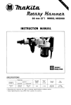
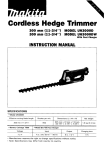
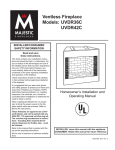
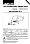
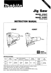
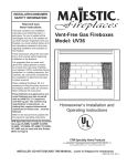
1
Rotary Hammer
25 mm (1") MODEL HR2511
Variable Speed
INSTRUCTION MANUAL
SPECIFICATIONS
Capacities
Wood
30"
(1-3116")
Steel
Concrete
1 3 mm
(112")
25 mm
(1")
No load speed
(RPM)
Overs"
length
Net
weight
3 3 5 mm
(13-3116")
(9.2 lbsl
~ ~ o per
w s min.
0 - 800
~
3,000
* Manufacturer reserves the right to change specifications without notice.
* Note: Specifications may differ from country t o country.
4.2 kg
IMPORTANT
SAFETY INSTRUCTI0NS
(For All Tools)
WARNING: WHEN USING ELECTRIC TOOLS, BASIC SAFETY
PRECAUTIONS SHOULD ALWAYS BE FOLLOWED TO REDUCE
THE RISK OF FIRE, ELECTRIC SHOCK, AND PERSONAL
INJURY, INCLUDING THE FOLLOWING:
READ ALL INSTRUCTIONS.
1. KEEP WORK AREA CLEAN. Cluttered areas and benches invite injuries.
2. CONSIDER WORK AREA ENVIRONMENT. Don't use power tools in damp
or wet locations. Keep work area well lit. Don't expose power tools t o rain.
Don't use tool in presence of flammable liquids or gases.
3.KEEP CHILDREN AWAY. All visitors should be kept away from work area.
Don't let visitors contact tool or extension cord.
4. STORE IDLE TOOLS. When not in use, tools should be stored in dry, and high
or locked-up place - out of reach of children.
5. DON'T FORCE TOOL. It will do the job better and safer at the rate for which
it was intended.
6. USE RIGHT TOOL. Don't force small tool or attachment t o do the job of a
heavy-duty tool. Don't use tool for purpose not intended; for example, don't
use circular saw for cutting tree limbs or logs.
7. DRESS PROPERLY. Don't wear loose clothing or jewelry. They can be caught
in moving parts. Rubber gloves and non-skid footwear are recommended
when working outdoors. Wear protective hair covering t o contain long hair.
8. USE SAFETY GLASSES. Also use face or dust mask if cutting operation is
dusty.
9. DON'T ABUSE CORD. Never carry tool by cord or yank it t o disconnect from
receptacle. Keep cord from heat, oil, and sharp edges.
IO. SECURE WORK. Use clamps or a vise t o hold work. It's safer than using
your hand and it frees both hands t o operate tool.
11. DON'T OVERREACH. Keep proper footing and balance at all times.
12. MAINTAIN TOOLS WITH CARE. Keep tools sharp and clean for better and
safer performance. Follow instructions for lubricating and changing accessories. Inspect tool cords periodically and if damaged, have repaired by
authorized service facility. Inspect extension cords periodically and replace
if damaged. Keep handles dry, clean, and free from oil and grease.
13. DISCONNECT TOOLS. When not in use, before servicing, and when changing
accessories, such as blades, bits, cutters.
2
14. REMOVE ADJUSTING KEYS AND WRENCHES. Form habit of checking t o
see that keys and adjusting wrenches are removed from tool before turning
it on.
15. AVOID UNINTENTIONAL STARTING. Don't carry tool w i t h finger on switch.
Be sure switch is OFF when plugging in.
16. EXTENSION CORDS. Make sure your extension cord is in good condition.
When using an extension cord, be sure t o use one heavy enough t o carry
the current your product will draw. A n undersized cord will cause a drop in
line voltage resulting in loss of power and overheating. Table 1 shows the
correct size t o use depending on cord length and nameplate ampere rating.
If in doubt, use the next heavier gage. The smaller the gage number, the
heavier the cord.
TABLE 1 MINIMUM GAGE FOR CORD SETS
Total Length of Cord in Feet
0-25
I
26 - 50
Ampere Rating
More
Not More
Than
Than
~~
I
51 - 100
~
-
6
10
12
16
101 - 150
A W G
~
0
6
10
12
I
18
18
16
14
16
16
16
12
;:
1
14
12
14
12
Not Recommended
3
VOLTAGE WARNING: Before connecting the tool t o a power source (receptacle,
outlet, etc.) be sure the voltage supplied is the same as that specified o n the
nameplate of the tool. A power source w i t h voltage greater than that specified
for the tool can result in SERIOUS INJURY t o the user - as well as damage t o
the tool. If in doubt, DO NOT PLUG IN THE TOOL. Using a power source with
voltage less than the nameplate rating is harmful t o the motor.
For all grounded tools w i t h American type plug.
GROUNDING INSTRUCTIONS: This tool should be grounded while in use t o
protect the operator from electric shock. The tool is equipped with a threeconductor cord and three-prong grounding-type plug t o fit the proper
grounding-type receptacle. The green (or green and yellow) conductor in the
cord is the grounding wire. Never connect the green (or green and yellow) wire
t o a live terminal. Your unit is for use on 115 volts and has a plug that looks
like Fig. "A'.
A n adapter Fig. "B" and "C" is available for connecting Fig. "A' type plugs
t o two-prong receptacles. The green-colored rigid ear, lug, etc., extending from
the adapter must be connected t o a permanent ground, such as a properly
grounded outlet box.
FIG. A
FIG. C
FIG. B
Adapter
I
4
Grounding Blade
Cover of Grounded Outlet
Box
ADDITIONAL SAFETY RULES
1. Wear a hard hat (safety helmet), safety glasses and/or face shield. It is also
highly recommended that you wear a dust mask, ear protectors and thickly
padded gloves.
2. Be sure the bit is secured in place before operation.
3. Under normal operation, the tool is designed to produce vibration. The screws
can come loose easily, causing a breakdown or accident. Check tightness
of screws carefully before operation.
4. In cold weather or when the tool has not been used for a long time, let the
tool warm up for several minutes by operating it under no load. This will loosen up the lubrication. Without proper warm-up, hammering operation is
difficult.
5. Always be sure you have a firm footing.
Be sure no one is below when using the tool in high locations.
6. Hold the tool firmly w i t h both hands.
7. Keep hands away from moving parts.
8. Do not leave the tool running. Operate the tool only when hand-held.
9. Do not point the tool at any one in the area when operating. The bit could
fly out and injure someone seriously.
IO. When drilling or chipping into walls, floors or wherever "live" electrical wires
may be encountered, DO NOT TOUCH ANY METAL PARTS OF THE TOOL!
Hold the tool by the insulated grasping surfaces t o prevent electric shock
if you drill or chip into a "live" wire.
11. Do not touch the bit or parts close t o the bit immediately after operation;
they may be extremely hot and could burn your skin.
SAVE THESE INSTRUCTIONS.
5
Bit grease
Coat the bit shank head beforehand with a small amount (about 0.5- 1g; 0.02-0.04 oz.)
of bit grease. This chuck lubrication assures smooth action and longer service life.
Installing or removing drill bit
CAUTION:
Always be sure that the tool i s switched off and unplugged before installing or removing
the bit.
To install the bit, press the change ring in
the direction of the arrow, align the key
groove on the bit shank with the red dot
and insert the bit. Now release the change
ring. If the change ring does not return to
i t s original position easily, turn the bit
slightly in either direction.
To remove the bit, press the change ring in
the direction of the arrow and the bit will
slip out.
Adjusting depth of drilling
Loosen the wing bolt and adjust the depth
gauge to the desired depth. After adjusting,
tighten the wing bolt.
6
I
I
1
Side grip (auxiliary handle)
The side grip swings around to either side,
allowing easy handling of the tool in any
position. Loosen the side grip by turning it
counterclockwise, swing it to the desired
position and then tighten it by turning
clockwise.
Selecting action mode
Rotation with hammering:
For drilling in concrete, granite, tile, etc.,
rotate the change lever to the
position.
lever
-
Rotation only:
For drilling in wood or metal, rotate the
change lever to the
position.
-3-
CAUTION :
To avoid rapid wear on the mode change mechanism, be sure that the change lever is
always positively located in one of the two action mode positions.
7
Switch action
Too speed is increased by increasing pressure on the trigger. To start the tool, simply
pull the trigger. Release the trigger to stop.
A speed control screw is provided so that
maximum tool speed can be limited (variable). Turn the speed control screw clockwise for higher speed, and counterclockwise for lower speed.
I
Speed control screw
CAUTION :
Before plugging in the tool, always check to see that the trigger switch actuates properly
and returns to the "OFF" position when released.
0
Do not tape, t i e or otherwise secure the trigger in the "ON" position.
Hammer drilling operation
Position the bit a t the location for the
hole, then pull the trigger.
Do not force the tool. Light pressure gives
best results. Keep the tool in position and
prevent it from slipping away from the
hole.
Do not apply more pressure when the hole
becomes clogged with chips or particles.
Instead, run the tool a t an idle, then remove from the hole. By repeating this
several times, the hole will be cleaned out.
8
Driving in anchor manually
The drill bit has a red marking a t a point
corresponding to the anchor length. So
drill to that depth.
Use the blow-out bulb to clean out the
hole.
Put a plug on the anchor and hammer it
into the concrete.
setting tool
hor setting rod)
Screw in a
bolt to fasten equipment.
Bolt
9
Dust collector
Use the dust collector for safe, sanitary
overhead operations. Install the bit, then
attach the dust collector on the end by
turning and applying pressure. Then secure
it by turning the metal retainer clockwise.
Metal retainer
CAUTION :
Empty the dust collector of i t s contents
after drilling every 2 or 3 holes.
Drilling in wood or metal
Set the change lever for "rotation only."
Use the optional drill chuck and chuck
adapter for drilling up to 13 mm (1/2") in
metal and up to 30 mm (1-3/16") in wood.
To install the drill chuck and chuck adapter,
refer to "installing or removing drill bit".
I
I
Drill chuck
Drill holder
1
CAUTION :
When the drill chuck is installed on this tool, do not use "rotation with hammering"
action. The drill chuck and chuck adapter may be damaged.
Core bit (optional accessory)
Screw the core bit on the adapter. Install
the core bit and adapter on the tool in the
same manner as a drill bit.
10
Install the center bit.
I
Center bit
Rest the core bit on the concrete and turn
the tool on. Once the core bit has cut a
shallow groove into the concrete, remove
the center bit. Then resume drilling.
To remove the core bit, hold the adapter
with the wrench, insert the rod into the
hole in the core bit and tap with a hammer
to unscrew.
11
MA1NTENANCE
CAUTION :
Always be sure that the tool is switched off and unplugged before attempting to perform
inspection or maintenance.
Replacing carbon brushes
When the resin insulating tip inside the
carbon brush i s exposed to contact the
commutator, it will automatically shut off
the motor.
When this occurs, both carbon brushes
should be replaced a t the same time. Use
only identical carbon brushes.
77
Insulating tip
J
Use a screwdriver to remove the brush
holder caps. Take out the worn carbon
brushes, insert the new ones and secure the
brush holder caps.
12
\
Carbon brush
Lubrication
This tool requires no hourly or daily lubrication because it has a grease-packed lubrication
system. It should be relubricated after every 6 months of operation. Send the complete
tool to Makita Authorized or Factory Service Center for this lubrication service.
However, if circumstances require that you should lubricate it by yourself, proceed as
follows.
Run the tool for several minutes to warm it up. Switch off and unplug the tool. Remove
the crank cap using a Makita lock nut wrench 35 (optional accessory). Rest the tool on
the table with the bit end pointing upwards. This will allow the old grease to collect
inside the crank housing. Wipe out the old grease inside and replace with a fresh grease
(30 g; 1 02). Use only Makita genuine grease (optional accessory). Filling with more than
the specified amount of grease (approx. 30 g; 1 02) can cause faulty hammering action or
tool failure. Fill only with the specified amount of grease. Reinstall the crank cap and
tighten with the lock nut wrench. Do not tighten the crank cap excessively. It is made of
resin and i s subject to breakage.
Sharpening tungsten-carbide tip bit
When your bit becomes dull, use an ordinary bench grinder with a wheel made of silicon
carbide to resharpen it.
CAUTION :
Be sure to maintain the original angles of the tip. Especially without 60" chamfering,
the tungsten-carbidetip may be damaged.
0 Do not quench the bit in water or oil.
0 Do not grind the sides B and C.
0
0 5 - k
A - A ' Cross section
To maintain product SAFETY and RELIABILITY, repairs, any other maintenance or
adjustment should be performed by Makita Authorized or Factory Service Centers,
always using Makita replacement parts.
13
ACCESSORIES
CAUTION :
These accessories or attachments are recommended for use with your Makita tool specified in this
manual. The use of any other accessories or attachments might present a risk of injury t o persons.
The accessoriesor attachments should be used only in the proper and intended manner.
0
Blow-out bulb
Part No. 765009-6
Tungsten-carbide tip bits
Part NO.
I
Diameter
I Overall length
0
Hex wrench 5
Part No. 783203-8
0
Lock nut wrench 35
Part No. 782407-9
0
Hammer grease 30 g; 102.
Part No. 181490-7
0
Drill chuck SI3
Part No. 763055-3
0Bitgrease 1OOg;3.5oZ.
Part No. 181573-3
0
Chuck adapter
Part No. 321637-3
0
Dust collector assembly
Part No. 122360-1
0
Chuck key SI3
Part No. 76341 1-7
0
Steel carrying case
Part No. 181798-9
'
-- _
14
li
a
oct -08-'91
us
25 mm (1")
ROTARY HAMMER
Model HR2511
Note: The switch and other part configurations
may differ from country to country.
15
oct -08-'91
MODEL HR2511
'LiM
AtD
'LiM
DESCRIPTION
MACHINE
2
4
5
6
7
8
9
10
11
12
13
14
15
16
18
19
21
22
23
24
25
4
1
2
1
1
1
1
1
1
1
1
1
1
1
4
1
1
1
1
1
1
2
1
1
1
1
I
26
27
26
29
30
31
32
33
34
35
38
37
38
39
40
41
42
43
44
45
1
1
1
1
1
1
1
1
1
1
2
1
1
I
46
1
1
47
,&
us
DESCRIPTION
E*
48
49
50
51
52
53
54
55
Hex Socket Head Bolt M6x25 lWtth Washer1
Ball Bearing 3009
Roller 6 5
Nut M 3 0 3 - 3 6
Barrel
ORing 48
Needle Bearing 3516
Flat Washer 35
Sporal Bevel Gear 33
Striker
56
57
58
59
Key4
O R i n g 19
ORing19
Piston
Hex Sockel Head Bolt M6145
Pin6
CrsnkCao
0 Ring 44
Rod
Needle Bearing 810
Crank Shalt
Steel Bsll 5 6
Comprsrrion Spr8ng 6
Change Pln 8
60
61
62
83
84
67
73
74
75
76
77
78
79
80
81
82
83
84
85
88
87
88
89
Clank HOUSlng
Ball Bearing 6002
nsiecai ear 36
Flat Washer 15
Ball Bearing 8902
O R i n g 90
ORing 7
Change Lever
Comprssalon SP""B 2
Steal 8811 4
Armature
Woodruff Key 3
FIELD ASSEMBLY
Hex Bolt M5x45 [With Washetl
0
1
1 SBBI 13
Ball Bearing 6200
93
94
95
98
97
98
99
1 w
Gear Housing
Thin Washer 1 5
Ball Bsaring 608
Note The switch and other part ~pec111catlonS
may dlfter from Counlry
1
1
1
1
1
1
3
1
1
1
1
3
1
1
1
1
1
1
1
4
1
1
2
2
1
1
1
3
1
3
2
1
1
1
2
1
1
Torque Limiter
Cap Square Neck Bolt M8135
Grip 32
Grip 88.8
Bell
Cylinder Liner 25
Sfeel Ball 6 4
011 seal 21
Fell Ring 20
0 Ring 44
Seal Holder
Steel Ball 8 4
Impact Bolt
0 Ring 10
0 Ring 10
Drill Holder
0 Ring 10
Change Ring
Motor Housmg
Rivet 0-5
Name Plate
Label
Carbon Brush
Brush Holder Cap
Fan 65
Ball Baaring 6OBLB
Bearing Box
Pan Head Screw M 5 r 2 8 IWllh Washer1
Handle Set [With Item 951
Pan Head Screw M5x25 [With Washer1
Pan Head Screw Max25 [With Washer)
Cord
Card Guard
Stram Relief
Pan Head Screw M 4 r l 8 IWilh Washer)
Switch
1
Dust Cover
Handle Set [With ltsm 831
Pan Head Screw M 6 x l 8 IWilh Washer]
Wing Bolt M5x15
Rubber Washer 4 5
Conical Comprssaon Spring 21 -25
1
cap 34
1
2
1
1
10 country
1
MAKKA LIMITEDONE YEAR WARRANTY
i
Warranty Policy
4
~
~ by~defective
& workmanship
~
~ or material,
d
Makita will rei
replace) without charge.
This Warranty does not apply where:
repairs have been made or attempted by others.
repairs are requmd because of normal wear and tear
The tool has been abused, misused or improperly maintamed:
alterations have been made to the tool.
I
IN NO EVENT SHALL MAKITA BE LIABLE FOR ANY INDIRECT INCIDkNTAL OR CONSEQUENTIAL DAMAGES FROM THE SALE OR USE OF THE P R O D ~ JTHIS
~ . DISCLAIMER
APPLIES BOTH DURING AND AFTER THE TERM OF THIS WARRANTY.
MAKITA DISCLAIMS LIABILITY FOR ANY IMPLIED WARRANTIES INCLUDING IMPLIED
WARRANTIES OF "MERCHANTABILITY" AND "FITNESS FOR
SPECIFIC PURPOSE,"
AFTER THE ONE-YEAR TERM OF THIS WARRANTY.
Tlus Warranty glves you specific legal rights and you may also have other nghts whlch vary from
state l o state. Some states d o not allow thk exclusion or limitation of incidental or consequential
damages, so the above limitallon or exclusion may not apply to you. Some States do not allow
limitation on how long an implied warranty lasts, so the above limitation may not apply to YOU.
A'
e
i
Makita Corporation
3-11-8, Sumiyoshi-cho,
Anjo, Aichi 446 Japan
883399D068
PRINTED IN JAPAN
1995 - 3 - N