1
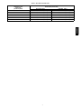
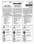
359AAV
UPFLOW / HORIZONTAL / DOWNFLOW
HIGH EFFICIENCY GAS FURNACE
Owner’s Manual
NOTE TO INSTALLER: THIS MANUAL MUST BE LEFT
WITH THE EQUIPMENT USER.
USER: Please read all instructions in the manual and retain all
manuals for future reference.
!
WARNING
CERTIFIED
DE
FIRE OR EXPLOSION HAZARD
S I GN
C
ER
Do not store or use gasoline or other flammable vapors and
liquids in the vicinity of this or any other appliance.
WHAT TO DO IF YOU SMELL GAS
--Do not try to light any appliance.
--Do not touch any electrical switch; do not use any
phone in your building.
--Leave the building immediately.
--Immediately call your gas supplier from a neighbor’s
phone. Follow the gas supplier’s instructions.
--If you cannot reach your gas supplier, call the fire
department.
Installation and service must be performed by a qualified
installer, service agency or the gas supplier.
!
WARNING
CARBON MONOXIDE POISONING HAZARD
Failure to follow this warning could result in personal
injury and/or death.
Carbon Monoxide is invisible, odorless, and toxic! A
carbon monoxide alarm is recommended in your home,
even if you do not own a gas appliance. Locate the carbon
monoxide alarm in the living area of your home and away
from gas appliances and doorways to attached garages.
Follow the alarm manufacturer’s instruction included with
the alarm.
Do not use this furnace if any part has been under water. A
flood--damaged furnace is extremely dangerous. Attempts to
use the furnace can result in fire or explosion. A qualified
service agency should be contacted to inspect the furnace
and to replace all gas controls, control system parts,
electrical parts that have been wet or the furnace if deemed
necessary.
D
Failure to follow safety warnings could result in injury, death,
or property damage.
TIFIE
As an ENERGY STAR
Partner, we have
determined that this
product meets the
ENERGY STAR guidelines
for energy efficiency.
ama
SAFETY CONSIDERATIONS
Recognize safety information. This is the safety--alert symbol
.
When you see this symbol on the furnace and in instructions or
manuals, be alert to the potential for personal injury.
Understand the signal words: DANGER, WARNING, and
CAUTION. DANGER identifies the most serious hazards which
will result in severe personal injury or death. WARNING signifies
hazards which could result in personal injury or death. CAUTION
is used to identify unsafe practices which may result in minor
personal injury or product and property damage. NOTE is used to
highlight suggestions which will result in enhanced installation,
reliability or operation.
To minimize the possibility of serious personal injury, fire, furnace
damage, or improper operation; carefully follow these safety
rules:
S Your gas furnace uses air from outside the home for combustion
and vents flue gas to the outdoors. It is not to be installed using
indoor air for combustion. The vent pipe must terminate outside
the structure and must not be obstructed in any way. The
air--intake pipe must terminate outside the structure or in a well
ventilated area that is isolated from the living space and the
garage (e.g. well ventilated attic or crawlspace). Do not block or
obstruct air openings on furnace or spaces around furnace.
S Keep the area around your furnace clear and free of combustible
materials, gasoline, and other flammable liquids and vapors.
1
Combustion Air (Your Safety)
!
Vent Pipe
WARNING
Draft Hood
Typical Gas
Water Heater
CARBON MONOXIDE POISONING HAZARD
Match
Failure to follow this warning could result in personal injury
or death.
All fuel--burning appliances must be provided with enough
fresh air for proper combustion and ventilation of flue gases.
A07688
Fig. 1 -- Water Heater Draft Hood
359AAV
Some models use air from the space in which they are located,
and other appliances in thesamespace may also be using
indoor air for ventilation and/or combustion.
a. Match flame pulls toward draft hood.
This indicates no spillage and that appliance is getting
enough air for combustion. Return exhausting devices
and appliances to the condition in which you found
them.
b. Match goes out or flame wavers away from draft hood.
This indicates spillage and that appliance is not getting
enough air for combustion.
New materials and methods are being used in construction and
remodeling which result in lower energy costs for heating and
cooling. It may also mean your appliances may not be getting
enough air for combustion and ventilation of flue gases. The use of
exhaust fans, fireplaces, clothes dryers, and other appliances
consume air or vent it to the outdoors.
If the gas appliances or heating furnace can’t get enough air, two
conditions may result:
1. The appliances or furnace may produce carbon monoxide
gas.
2. The appliance may not vent flue gases properly. The following are signs that your appliances may not be getting
enough air for proper combustion.
!
CARBON MONOXIDE POISONING HAZARD
Failure to follow this warning could result in personal injury
or death.
Draft hood spillage means there is not enough air for proper
combustion and carbon monoxide may be present.
Be aware of these signals:
1. Headaches, Nausea, Dizziness
2. Excessive humidity----heavily frosted windows or a moist
“clammy” feeling in the structure.
3. Smoke from the fireplace won’t draw up the chimney.
!
Keep a window open a minimum of 2” (50.8 mm) near the
appliance until a permanent combustion air duct is installed.
Contact a qualified service agency.
If draft hood spillage is indicated:
1. Check for plugged vent connectors and chimneys. Repair
stoppage and test again.
2. If you have a fireplace, open a window or door near the fireplace and then check for spillage. If spillage stops, do not
use the fireplace until you can supply fresh air by a permanent duct.
3. If you have kitchen and bathroom exhaust fans, turn them
OFF and check for spillage. If spillage stops, do not use exhaust fans until you can supply fresh air by a permanent
duct. Circuit breakers for fans should be turned off and
marked as to why they are off.
4. Spillage means air starvation and that an outdoor air duct or
air intake must be installed to provide air directly to the area
around the furnace. This duct or intake MUST comply with
local and state building codes or in their absence with the
National Fuel Gas Code NFPA 54/ANSI Z223.1--2006 in
the U.S., or the National Standard of Canada, Natural Gas
and Propane Installation Code CSA B--149.1--2006 in
Canada.
WARNING
CARBON MONOXIDE POISONING HAZARD
Failure to follow this warning could result in personal injury
or death.
If you experience headaches, nausea, or dizziness, carbon
monoxide may be present. Leave the house immediately and
call your gas supplier.
Combustion Air Checks
If any of the above signals are noticed, perform a combustion air
check or call a qualified service agency. If you add weather
stripping, storm windows, insulation, an additional fuel burning
appliance, or remodel the structure, a combustion air check MUST
be accomplished after the addition.
Make the inspection as follows:
1. Close all doors and windows. If you have a fireplace, start a
fire and wait until flames are burning vigorously.
2. Turn on all exhausting devices, such as: kitchen and bathroom exhaust fans and dryers (gas or electric).
3. Turn on all vented gas appliances, such as: heating equipment (includes any room heaters) and water heaters.
4. Wait ten (10) minutes for drafts to stabilize.
5. On appliances with a draft hood, check for spillage by holding a lighted match 2” (50.8 mm)from the draft hood opening. Reference Fig. 1, which shows a water heater draft
hood.
WARNING
Indoor Humidity (Your Comfort)
Relative humidity is important to your health. Proper
humidification helps cut down incidences of respiratory illness. Air
that is too wet may damage the building structure. Air that is too
dry is uncomfortable. A quick way to test for proper humidity is as
follows:
1. Look for frequent fogging or excessive condensation on the
inside of windows. This indicates the indoor humidity level
is too high for outdoor weather conditions.
2. Drop three ice cubes into a glass of water and stir. If, within
three minutes, moisture does not form on the glass, the air is
too dry and a humidifier would be beneficial. (Do not per2
About Your Furnace
Fig. 2 shows the location of the components in the furnace.
Circulating Air Blower
The blower circulates room air through the furnace, air ducts, and
into the rooms of the structure. The blower can be set at the
thermostat for automatic or manual operation. In manual mode the
blower operates continuously. In automatic, the blower does not
come on until a preset time after the gas valve is energized. When
the structure reaches the temperature set on the thermostat, the
furnace will shut off. The blower will continue to run until the
furnace cools down.
Thermostat
There are many types and styles of thermostats. Most thermostats
control both heating and cooling functions and have a Fan Switch
with AUTO and ON settings. On AUTO, the Circulating Air
Blower will cycle on/off with the furnace on the heating speed
unless a call for cooling is initiated. Blower speed will correspond
to the mode of operation of the furnace. If the Fan Switch is
positioned to ON the blower will run continuously.
In addition some thermostats are programmable with multiple set
backs. The set backs can be pre--programmed to lower or raise the
temperature automatically.
Be sure to become familiar with your thermostat.
Rating Plate
The rating plate contains important information for the service
technician and lists the complete model, manufacturing and serial
numbers. You should always provide all these numbers when
requesting parts or if you need service. See Fig. 2 for rating plate
location.
Door Interlock Switch
All the electrical power for the furnace goes through the door
interlock switch. The interlock switch interrupts electrical power to
the furnace when the blower door is removed. The furnace will not
operate until the blower door is reinstalled.
Furnace Control
The furnace control provides power to the circulating air blower to
keep it on until the furnace cools down.
The fan off--delay setting can be adjusted if the fan remains on long
enough that cool drafts are felt in the room after the furnace shuts
off.
Furnace Vent Pipe (Vent Pipe Connections through Side Panel on Some Models-
Air Intake Pipe
(Required only for Direct-- Vent Furnaces)
Manual Gas Shutoff Valve
Vent Pipe Grommet
Ignitor & Flame Sensor
(not shown)
Primary Heat Exchanger
Vent Drain Fitting
Furnace Main Gas Control Valve
Combustion Blower
5 /8″ I.D.
1/ ″ I.D. Vent Pipe Drain Hose
2
Transition Box Drain Hose
Secondary Heat Exchanger
Door Interlock Switch
Pressure Switches
(some models have one)
Condensate Trap
Plastic Transition Box
Diagnostic Light
Furnace Control
Circulating Air Blower
Rating Plate
Representative drawing only, some models may vary in appearance.
A09280
Fig. 2 -- Component Locations for Condensing 90+ Furnaces
3
359AAV
form this test in the kitchen, cooking vapors may produce
inaccurate results.)
A good relative humidity is one just high enough to barely start
condensation along the lower edges or lower corners of the
windows, when it is cold outside. More than that can be damaging.
If the humidity is too high, try these suggestions to lower the
humidity:
1. Reduce setting or discontinue use of humidifier.
2. Use range and bathroom exhaust fans while cooking and
bathing. Open a door or window for a few minutes to bring
in cool drier air.
3. Cook with pans covered.
4. Take shorter baths or showers with cooler water.
5. Install a fresh air intake duct. Cold, dry air brought in from
outside to the furnace area lowers the indoor humidity level.
6. Have appliances checked. A malfunctioning appliance can
contribute water vapor to the structure.
7. If the problem continues, consult a heating contractor about
adding a heat recovery ventilator or air--to--air heat exchanger.
359AAV
The off--delay is set by moving a jumper on the control. The
Wiring Diagram located on the inside of the blower door shows the
various delay combinations. Refer to Fig. 2 for location of the
control.
If you are unsure how to set the Off--delay Control, contact a
Qualified Service Agency.
Set the room thermostat slightly above room temperature. This will
automatically signal the furnace to start. The inducer motor will
start, and the hot surface igniter will have an orange glow. After
about 32 seconds (from the call for heat at the thermostat), the gas
valve permits gas to flow to the main burners where it is ignited.
When the flame is firmly established, the igniter shuts off. Hot
flames begin to warm the furnace’s heat exchanger. After a time
delay of 30 seconds, the furnace blower is switched on.
NOTE: If the main burners fail to ignite, the furnace control
system will go through 3 more ignition cycles. Then, if burners fail
to ignite, the system will lockout. If lockout occurs, or the blower
doesn’t come on, shut down your furnace and call a Qualified
Service Agency for service.
Pressure Switch
The furnace is equipped with one or more pressure switches to shut
down the furnace under various flue conditions. The switches are
connected to the furnace by factory supplied tubing.
Should overheating occur or the gas control valve fail to shut
off, shut off the manual equipment shutoff valve to the furnace
before shutting off the electrical supply.
Extended Shutdown
1. Set thermostat to lowest temperature setting or set thermostat System Select Switch to OFF, if so equipped.
2. Turn Manual Equipment Shutoff Valve for furnace to OFF
position (at right angle or 90_ to gas line).
3. Remove the burner compartment door by removing the two
(2) screws securing the door in front and lifting the door up
and outwards. Removing the door will expose the gas control valve knob.
4. Turn OFF electric power to the furnace at the disconnect
switch or circuit breaker. (May be left ON for set--back type
thermostat with batteries, provided thermostat has system
select switch placed in the OFF position.)
5. Turn the the gas control valve to the OFF position. See Fig.
3.
6. Reinstall all doors.
Propane Gas Model Furnaces
!
Operating Your Furnace
FIRE OR EXPLOSION HAZARD
Keep the blower access door and all access panels in place except
for inspection or maintenance.
Before starting your furnace be sure you read and understand all of
the procedures in this manual. Check to make sure the furnace filter
is clean and correctly installed.
!
Failure to follow this warning could result in property damage,
personal injury or death.
Propane gas is heavier than air. Leaking gas could settle in low
areas such as crawl space. If you suspect the presence of gas,
follow the instructions on the cover of this manual.
WARNING
CARBON MONOXIDE POISONING HAZARD
Failure to follow this warning could result in personal injury
or death.
Provisions for combustion and ventilation air must be
provided for in accordance with installation instructions
supplied with furnace.
If your propane gas furnace is installed in an excavated or low
lying area, we recommend that you contact your propane gas
supplier about installing a warning device that would alert you of a
gas leak.
Frozen Water Pipe Hazard
!
CAUTION
PROPERTY DAMAGE HAZARD
Starting The Furnace
See Fig. 4 for an illustration of the gas control valve.
1. Turn the thermostat to its lowest temperature setting or to
OFF if equipped with a System Select Switch.
2. Turn OFF all electric power to the furnace at the disconnect
switch or circuit breaker.
3. Remove the burner compartment door by removing the
two(2) screws securing the door in front and lifting the door
up and outwards. Removing the door will expose the gas
control valve knob.
4. Turn the gas control valve to the OFF position. See Fig. 3.
5. Wait five (5) minutes to clear out any gas. If you then smell
gas, STOP! Follow the safety information on the cover of
this manual. If you do not smell gas, go to the next step.
6. Turn the gas control valve to the ON position. See Fig. 3.
7. Reinstall all doors.
8. Turn ON all electrical power to the furnace.
9. Set the thermostat to the desired temperature and the System
Select Switch to HEAT.
The furnace will activate an igniter which lights the main burners.
WARNING
Failure to follow this caution may result in property damage
Furnace may shut down. Do not leave your home unattended
for long periods during freezing weather without turning off
water supply and draining water pipes or otherwise protecting
against the risk of frozen pipes.
Your furnace is designed solely to provide a safe and comfortable
living environment. The furnace is NOT designed to ensure that
water pipes will not freeze. It is equipped with several safety
devices that are designed to turn the furnace off and prevent it from
restarting in the event of various potentially unsafe conditions.
If your furnace remains off for an extended time, the pipes in your
home could freeze and burst, resulting in water damage. If the
structure will be unattended during cold weather, you should take
these precautions.
1. Turn off the water supply to the structure and drain the water lines if possible and add an antifreeze for potable water
to drain traps and toilet tanks. Open faucets in appropriate
areas.
--or--
Turning Off The Furnace
Set the thermostat to the lowest temperature setting or set System
Select Switch to OFF, if so equipped.
4
Single Stage
Pressure Switches
During regular yearly maintenance, check for cracks in any tubes
on the pressure switches.
INLET
!
WARNING
ELECTRICAL SHOCK HAZARD
Failure to follow this warning could result in personal injury
or death.
On\Off
toggle
switch
Turn off electrical power to furnace before performing any
maintenance or removing panels or doors.
OUTLET
1/4” Spade
Connection
2. Have someone check the structure frequently during cold
weather to make sure it is warm enough to prevent pipes
from freezing. Instruct them to call a qualified service
agency to call to provide service, if required.
--or-3. Install a reliable remote sensing device that will notify
somebody of freezing conditions within the home.
Winter Shutdown (90+ Furnaces)
If you go away during the winter months and do not leave the heat
on in your home, the plastic transition box and the condensate trap
on the furnace must be protected from freeze damage. (See Fig. 2)
1. Disconnect the 1/2” I.D. rubber hose from the vent drain fitting (or tee) that is located downstream of the combustion
blower. Insert a funnel into the hose and pour four (4)
ounces of sanitary type (RV) antifreeze into the condensate
trap. Reconnect the 1/2” I.D. rubber hose to the stub on the
vent drain fitting. Secure with the hose clamp.
2. Disconnect the 5/8” I.D. rubber hose from the condensate
trap. Insert a funnel into the hose and pour four (4) ounces
of sanitary type (RV) antifreeze into the plastic transition
box. Squeeze the hose together near the end and quickly reconnect the 5/8” I.D. rubber hose to the stub on the condensate trap. Secure with the hose clamp.
3. When you return home, your furnace will be ready to start,
as it is not necessary to drain the antifreeze from the furnace.
Furnace Maintenance
Have your furnace inspected and serviced on an annual basis
(before the heating season) by a qualified service agency.
Labeling
!
WARNING
FIRE OR EXPLOSION HAZARD
Failure to follow this warning could result in personal injury
or death.
Label all wires prior to disconnection when servicing controls.
Verify proper operation after servicing. Only qualified service
agencies should attempt electrical service.
Air Filters/Monthly
The air filter(s) should be inspected at least monthly and cleaned or
replaced as required. There are many types of filters that are
commonly used. Washable filters (constructed of aluminum mesh,
foam, or reinforced fibers) may be cleaned by soaking in mild
detergent and rinsing with water. The fiberglass disposable type
should be REPLACED before it becomes clogged. Other filter
types should be serviced in accordance with the manufacturer’s
recommendations.
Remember that dirty filters are the most common cause of
inadequate heating or cooling performance.
Replacement Filters
If the filter is not located at or within the furnace, it should be
located somewhere in the return--air duct system.
The recommended sizes and types of filters that may be used with
your furnace are based on the furnace’s heating gas input rate (and
cooling system capacity, if so equipped).
Replacement filters should be of the same type and size as the
original filters, to ensure adequate air flow and filtering. A
disposable low velocity filter can be replaced with a washable high
velocity type. Do not replace a high velocity filter with a
disposable low velocity filter, except as permitted below.
If a cleanable (high--velocity) filter(s) is to be replaced with a
disposable (low--velocity) filter(s), the airflow area of the filter(s)
must be doubled (i.e., a second filter of the same size must be
installed so that only half of the air goes through each filter). A
second return--air duct to the furnace may be required in which to
install the second filter. Modification of a furnace installation shall
comply with the local installation code and the furnace installation
instructions, and shall be made only by a Qualified Service
Agency.
NOTE: Some filters are marked with an arrow to indicate the
proper direction of air flow through the filter. The air flow
direction will be towards the blower motor. Make sure filter is
installed correctly.
NOTE: Some units are equipped with filter rack.
Filter Replacement -- Upflow
The filter may be installed inside the bottom of the furnace blower
compartment, or the filter(s) rack may be installed under the
furnace or on either or both sides of the furnace. A plastic end
cap(s) is inserted in the filter rack(s) after the filter(s) is installed.
The end cap keeps air from escaping around the open end of the
filter rack. See Fig. 4 and Fig. 5 for side and bottom locations.
Rack end cap is similar for bottom mounted filter rack.
5
359AAV
A07694
Fig. 3 -- Gas Control Valve
Filter rack(s) attached to the outside of the furnace is made so the
filter simply slides out one end for removal.
!
CAUTION
Center Clip
side-- to-- side
PROPERTY DAMAGE HAZARD
Failure to follow this warning could result in increase furnace
operating temperatures and shorten the life of the furnace.
Filters specified for the furnace are rated at a maximum of 600
FPM air velocity and sized for the furnace’s airflow rate.
Replacement filters must be of equivalent type, size, and rating
except as described below.
359AAV
Disposable, low--velocity filters may be used to replace
washable, high--velocity filters, providing they are sized for
300 FPM or less.
9″
If you are uncertain of the type of replacement filter to use,
consult the furnace installer or a qualified service agency for
assistance.
Filter Replacement -- Bottom or Side Mounted
Filter Rack Outside Furnace
1.
2.
3.
4.
A07691
Fig. 5 -- Bottom Mounted Filter Inside Furnace
External Filter Rack
Turn OFF electric power to furnace.
Remove the end cap from the filter rack.
Slide the filter out of the filter rack. See Fig. 4.
Inspect the filter(s) and replace or clean washable types. If
filter is aluminum mesh it should be recoated with filter
coating spray.
A plastic end cap is inserted in the filter rack after the filter is
installed. The end cap keeps air from escaping around the open end
of the filter rack. See Fig. 4 for removal of filter.
Filter racks attached to the furnace are made so the filter simply
slides out one end for removal.
1. Turn OFF electric power to furnace.
2. Remove the end cap from the filter rack.
3. Slide the filter out of the filter rack.
4. Inspect the filter(s) and replace or clean washable types. If
filter is aluminum mesh it should be recoated with filter
coating spray.
5. Reinstall the end cap in the filter rack.
6. Turn furnace on.
Internally Mounted Filter
1.
2.
3.
4.
Turn OFF power to furnace.
Remove blower door.
Slide filter straight out toward you. (See Fig. 5.)
Inspect the filter(s) and replace or clean washable types. If
filter is aluminum mesh it should be recoated with filter
coating spray.
5. Replace blower door.
6. Turn on electric power to furnace.
Filter Rack End Cap
Lubrication
A07690
Fig. 4 -- Filter Rack Outside Furnace
5. Reinstall the end cap in the filter rack.
6. Turn on electric power to furnace.
Filter Replacement -- Bottom Mounted Filter
Inside Furnace
1.
2.
3.
4.
Turn off electric power to furnace.
Remove blower door.
Slide filter straight out toward you. See Fig. 5.
Inspect the filter(s) and replace or clean washable types. If
filter is aluminum mesh it should be recoated with filter
coating spray.
5. Replace blower door.
6. Turn on electric power to furnace.
The blower motor and the combustion air blower are
pre--lubricated by the manufacturer and DO NOT require oiling.
Qualified Service Agency Checks
When the furnace is being inspected for condition and operation
have the Qualified Service Agency check the following items.
1. Check all flue gas passages including main and pilot burners, heat exchanger, and vent.
2. Check electrical wiring and connections.
3. Check supply and return air ducts for leakage, blockage and
connections to furnace.
4. Check circulating air blower wheel and motor. Clean them
if required.
5. Perform an operational checkout on the furnace to be sure
safety controls function and that furnace operates properly.
For additional information, the Qualified Service Agency can
consult the installation instructions for the furnace.
6
Table 1 – Recommended Filter Sizes
Recommended Filter Sizes
Nominal Size (inches/mm)
Nominal Air Flow
Cubic Feet
per Minute (CFM)
Disposable Filters
Cleanable Filters
800--900
20 x 25 (508.0 x 635.0) (1 Req.)
14 x 25 (355.6 x 635.0) (1 Req.)
14 x 25 (355.6 x 635.0) (2 Req.)
14 x 25 (355.6 x 635.0) (1 Req.)
16 x 18 (406.4 x 457.2) (2 Req.)
16 x 18 (406.4 x 457.2) (1 Req.)
1500--1700
20 x 25 (508.0 x 635.0) (2 Req.)
20 x 25 (508.0 x 635.0) (1 Req.)
1900--2100
20 x 30 (508.0 x 762.0) (2 Req.)
20 x 25 (508.0 x 635.0) (1 Req.)
2300--2500
20 x 30 (508.0 x 762.0) (2 Req.)
24 x 30 (609.6 x 762.0) (1 Req.)
359AAV
1100--1300
1300--1500
7
359AAV
Heating & Cooling Systems
TO OBTAIN INFORMATION ON PARTS: Consult your installing dealer or classified section of your local telephone directory under the
“Heating Equipment” or “Air Conditioning Contractors & Systems” heading for dealer listing by brand name.
Have available the Model No., Series Letter, & Serial No. of your equipment to ensure correct replacement part.
Copyright 2009 Bryant Heating & Cooling Systems, 7310 W. Morris St. Indianapolis, IN 46231 Printed in the U.S.A.
Manufacturer reserves the right to change, at any time, specifications and designs without notice and without obligations.
8
Edition Date: 05/09
Catalog No:OM359AAV ---01
Replaces: New